Kenmore 625348320 User Manual WATER SOFTENER Manuals And Guides L0801179
KENMORE Water softener Manual L0801179 KENMORE Water softener Owner's Manual, KENMORE Water softener installation guides
User Manual: Kenmore 625348320 625348320 KENMORE WATER SOFTENER - Manuals and Guides View the owners manual for your KENMORE WATER SOFTENER #625348320. Home:Plumbing Parts:Kenmore Parts:Kenmore WATER SOFTENER Manual
Open the PDF directly: View PDF ![]() .
.
Page Count: 36
_ARS
OWNER'S
MANUAL
MODEL NO.
625.348320
Caution:
Read and Follow
All Safety Rules and
Operating Instructions
Before First Use of
This Product.
If you have questions when
installing, operating or main-
taining your softener, and
when setting the timer, call
this toll-free number...
1-800-426-9345
SAVE THIS MANUAL
SOLID STATE
Water Softener
Warranty
Start Up /Setting Timer
How It Works
Care Of /Troubleshooting
Specifications
Repair Parts
Use plastic bag and tie provided, to hang manuals nearby
the softener for future reference.
Sears, Roebuck and Co., Hoffman Estates, IL 60179 USA
PRINTED IN U.S.A.
WARRANTY
I]
SEARS RESIDENTIAL WATER SOFTENER
FULL ONE YEAR WARRANTY ON WATER SOFTENER
For one year from the date of purchase, when this water softener is installed and maintained
in accordance with our instructions, Sears will repair, free of charge, defects in material or
workmanship in this water softener.
FULL TEN YEAR WARRANTY AGAINST LEAKS
For ten years from the date of purchase, Sears will furnish and install a new current model
water softener tank or salt storage drum, free of charge, if either the tank or drum develop
a leak.
TO OBTAIN WARRANTY SERVICE, SIMPLY CONTACT THE NEAREST SEARS SER-
VICE CENTER THROUGHOUT THE UNITED STATES. This warranty applies only while
this product is in use in the United States.
This warranty gives you specific legal rights, and you may have other rights which vary from
state to state.
Sears, Roebuck and Co., D/817 WA, Hoffman Estates, IL 60179
If you want your water softener professionally installed, talk to your Sears Salesman. He will arrange for a
prompt, quality installation by Sears Authorized Installers.
SEARS INSTALLATION POLICY
All installation labor arranged by Sears shall be
perfbrmed in a neat, workmanlike manner in
accordance with generally accepted trade practic-
es. Ful_her, all installations shall comply with all
local laws, codes, regulations, and ordinances.
Customer shall also be protected, during installa-
tion, by insurance relating to Property Damage,
Workman's Compensation and Public Liability.
SEARS INSTALLATION WARRANTY
In addition to any warranty extended to you on the
Sears merchandise involved, which warranty
becomes effective the date the merchandise is
installed, should the workmanship of any Sears
arranged installation prove faulty within one year,
Sears will, upon notice from you, cause such faults
to be corrected at no additional cost to you.
FACTS AND FIGURES TO KEEP
Fill in the blanks below and keep this book in a safe
place so you always have these facts.
Water Softener Model No.1-
Serial Number
Date Installed
Water Hardness
Iron Content
*pH
Water Pressure
Water Flow Rate
Grains Per Gallon
Parts Per Million
Taste And/Or Odor
Pounds/Square Inch
Gallons Per Minute
1-The model number is on the rating decal, located
on the rim, under the salt hole cover.
2
TABLE OF CONTENTS
I 1
PAG E
NO.
SECTION 1SOFTENER START UP
A. SAFETY GUIDES
B. CHECK LIST OF STEP-BY-STEP GUIDES TO INSTALL
C. PROGRAM THE TIMER
D. SANITIZING THE WATER SOFTENER
E. FILL THE STORAGE TANK WITH SALT
4
5
6
7
8
SECTION 2 HOW YOUR WATER SOFTENER WORKS
A. FACE PLATE TIMER FEATURES 9-10
B. SOFT WATER SERVICE AND REGENERATION 11-13
SECTION 3CARE OF YOUR SOFTENER
A. SALT: REFILLING STORAGE TANK, SALT BRIDGE
B. KEEPING THE WATER SOFTENER CLEAN
C. KEEP THE SOFTENER FROM FREEZING
D. HELPFUL HINTS CHECKLIST
14
15
16
17
SECTION 4 OTHER THINGS TO KNOW
A. HOW TO "FINE-TUNE" YOUR WATER SOFTENER
B. DIMENSIONS/SPECIFICATIONS
18-20
21
SECTION 5 SERVICE TECH INFORMATION
A. ELECTRICAL CONNECTIONS
B. REGENERATION CYCLE TIMES
C. TROUBLESHOOTING
D. ROTARY VALVE SERVICE
E. WATER FLOW THROUGH THE SOFTENER VALVE
22
23
24-26
27
28-30
SECTION 6REPAIR PARTS 32-35
3
SECTION 1 WATER SOFTENER START-UP
1A. SAFETY GUIDES
•Read all steps, guides and rules carefully be-
fore installing and using your new water softener.
Follow all steps exactly to correctly install. Fail-
ure to follow them could cause personal injury or
property damage. Reading this book will also
help you to get all of the benefits from your water
softener.
• Your water softener will remove hardness min-
erals and "clear water" iron from water, up to the
limits shown on page 21. It will not remove other
types of iron, acids, tastes and odors, etc. It will
not purify polluted water or make it safe to drink.
• Protect the softener and piping from freezing.
Damage from freezing voids the softener warran-
ty. See page 16.
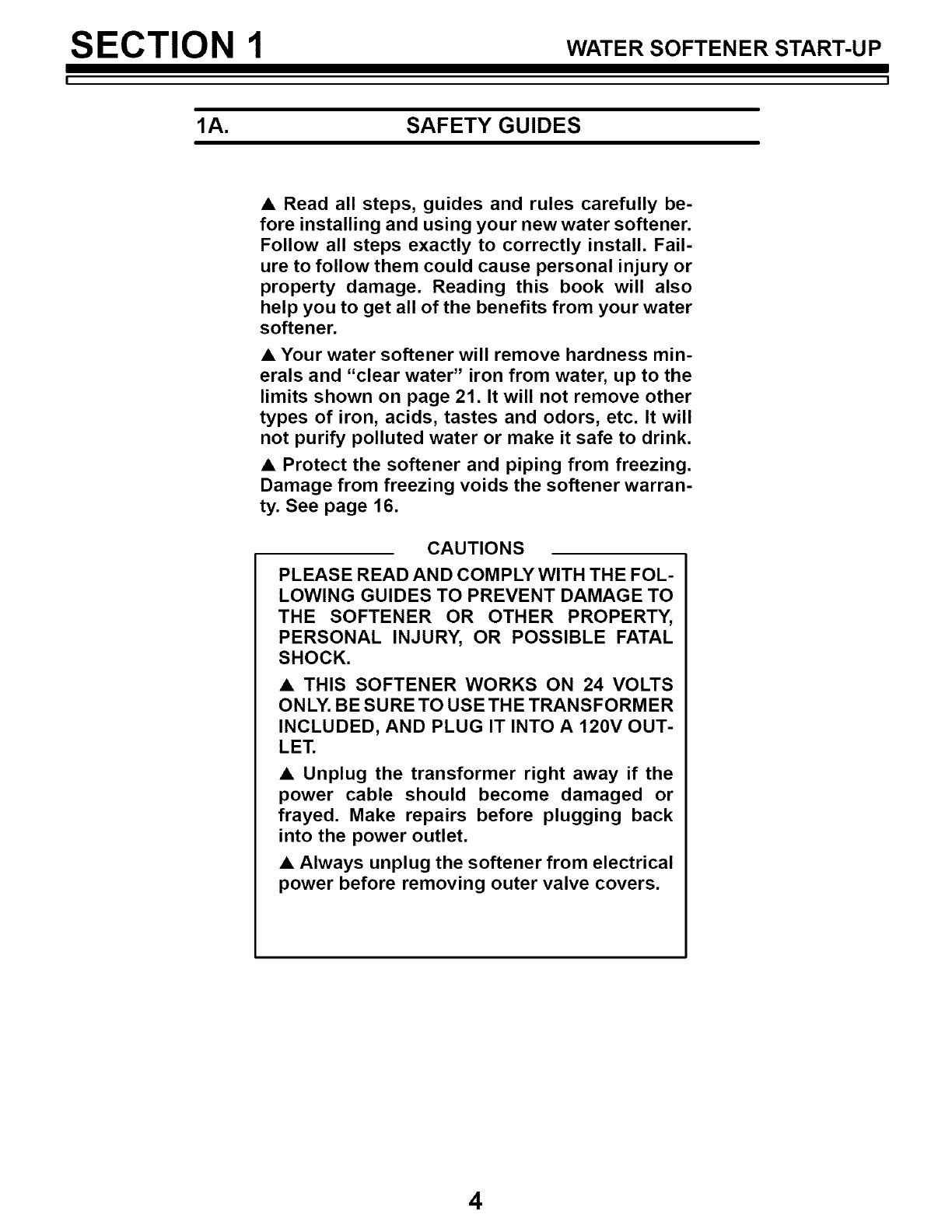
CAUTIONS
PLEASE READ AND COMPLY WITH THE FOL-
LOWING GUIDES TO PREVENT DAMAGE TO
THE SOFTENER OR OTHER PROPERTY,
PERSONAL INJURY, OR POSSIBLE FATAL
SHOCK.
• THIS SOFTENER WORKS ON 24 VOLTS
ONLY. BE SURE TO USE THE TRANSFORMER
INCLUDED, AND PLUG IT INTO A 120V OUT-
LET.
• Unplug the transformer right away if the
power cable should become damaged or
frayed. Make repairs before plugging back
into the power outlet.
• Always unplug the softener from electrical
power before removing outer valve covers.
4
SECTION 1 WATER SOFTENER START-UP
lB. CHECK LIST OF ALL STEP-BY-STEP GUIDES TO INSTALL
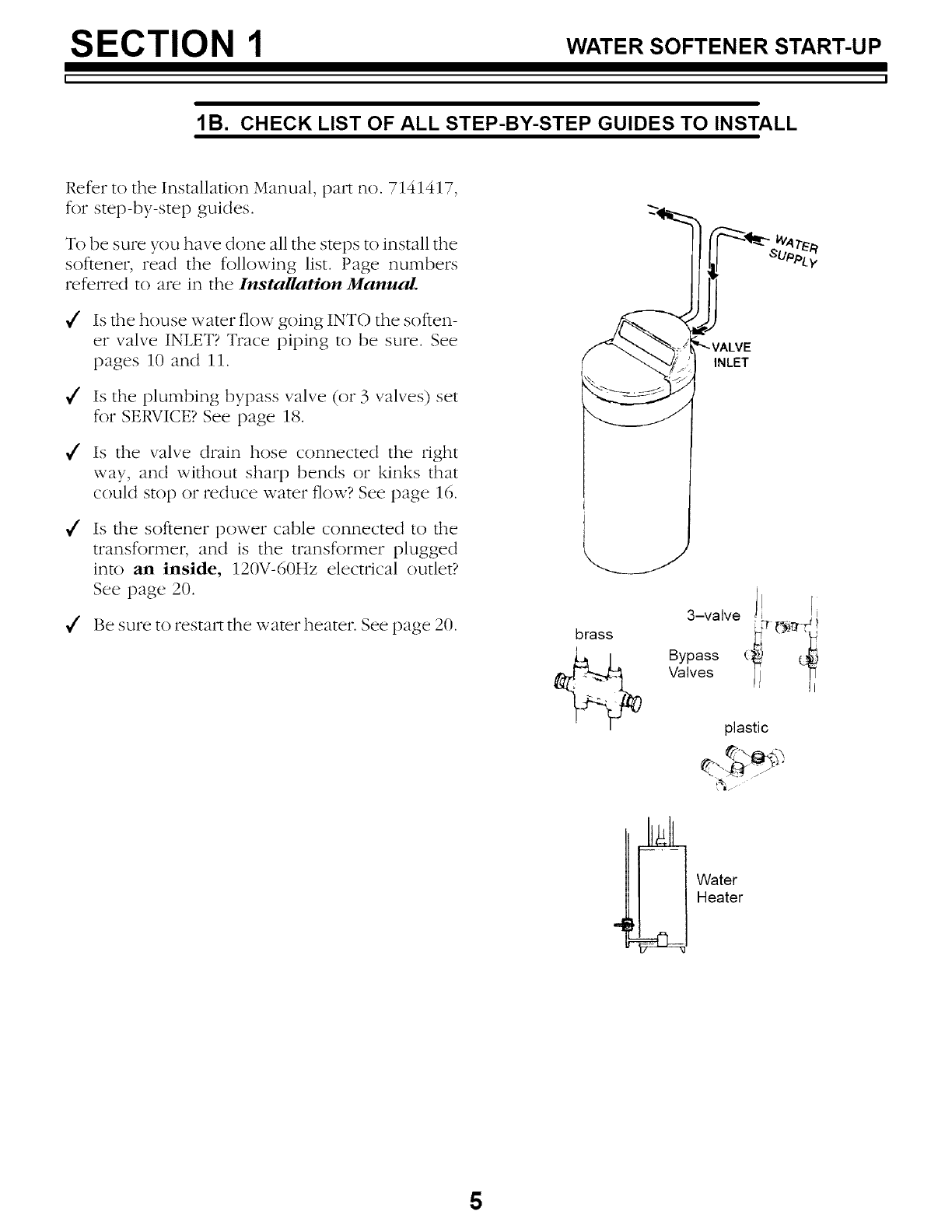
Refer to the Installation Manual, pm_ no. 7141417,
for step-by-step guides.
To be sure you have done all the steps to install the
softener, read the following list. Page numbers
referred to are in the Installation Manual.
_/' Is the house water flow going INTO the soften-
er valve INLET? Trace piping to be sure. See
pages 10 and 11.
_/' Is the plumbing bypass valve (or 3 valves) set
for SERVICE? See page 18.
_/' Is the valve drain hose connected the right
way, and without sharp bends or kinks that
could stop or reduce water flow? See page 16.
_/' Is the softener power cable connected to the
transformer, and is the transformer plugged
into an inside, 120V-60Hz electrical outlet?
See page 20.
_/' Be sure to restart the water heater. See page 20.
i
brass
INLET
3 , l! I,
-vawe 15 ('___r_/1
plastic
Water
Heater
5
SECTION 1 WATER SOFTENER START-UP
lC. PROGRAM THE TIMER
FQPRESENT TIME
_RECHARGE TIME
_RECHARGE DAY
(_ SET/CLEAR
03 °2°:FRA='&ow
display buttons
Solid State Water Softener
J
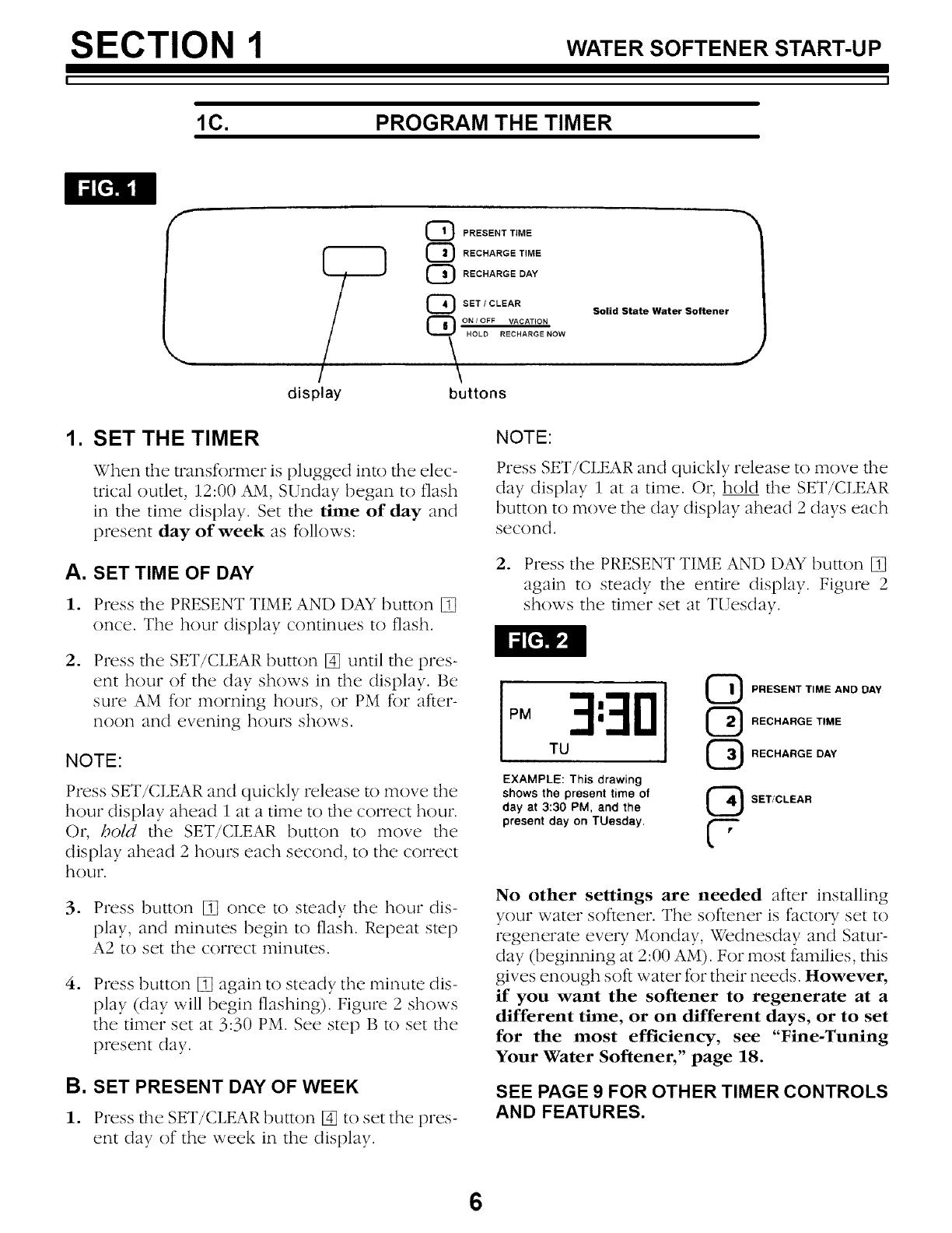
1. SET THE TIMER
When the transffwmer is plugged into the elec-
trical outlet, 12:00 AM, SUnday began to flash
in the time display. Set the time of day and
present day of week as fLllows:
A. SET TIME OF DAY
1. Press the PRESENT TIME AND DAY button []
once. The hour display continues to flash.
°Press the SET/CLEAR button [] until the pres-
ent hour of the day shows in the display. Be
sure AM for morning hours, or PM for after-
noon and evening hours shows.
NOTE:
Press SET/CLEAR and quickly release to move the
hour display ahead 1 at a time to the correct hour.
Or, bold the SET/CLEAR button to move the
display ahead 2 hours each second, to the correct
hour.
3. Press button [] once to steady the hour dis-
play, and minutes begin to flash. Repeat step
A2 to set the correct minutes.
.Press button [] again to steady the minute dis-
play ((lay will begin flashing). Figure 2 shows
the timer set at 3:30 PM. See step B to set the
present day.
B. SET PRESENT DAY OF WEEK
1. Press the SET/CLEAR button [] to set the pres-
ent day of the week in the display.
NOTE:
Press SET/CLEAR and quickly release to move the
day display 1 at a time. Or, hold the SET/CLEAR
button to move the day display ahead 2 days each
second.
2. Press the PRESENT TIME AND DAY button []
again to steady the entire display. Figure 2
shows the timer set at TUesday.
TU
EXAMPLE: This drawing
shows the present time of
day at 3:30 PM, and the
present day on TUesday,
QRESENT TIME AND DAY
RECHARGE TIME
RECHARGE DAY
SET/CLEAR
U
No other settings are needed after installing
your water softener. The softener is factory set to
regenerate every Monday, Wednesday and Satur-
day (beginning at 2:00 AM). For most families, this
gives enough soft water fi)r their needs. However,
if you want the softener to regenerate at a
different time, or on different days, or to set
for the most efficiency, see "Fine-Tuning
Your Water Softener," page 18.
SEE PAGE 9 FOR OTHER TIMER CONTROLS
AND FEATURES.
6
SECTION 1 WATER SOFTENER START-UP
1D. SANITIZING THE WATER SOFTENER
Care is taken at the factory to keep your water
softener clean and sanitary. Materials used to
make the softener will not infect or contaminate
your water supply, and will not cause bacteria to
form or grow. However, during shipping, storage,
installing and operating, bacteria could get into
the softener. For this reason, sanitizing as follows
is suggested <b when installing.
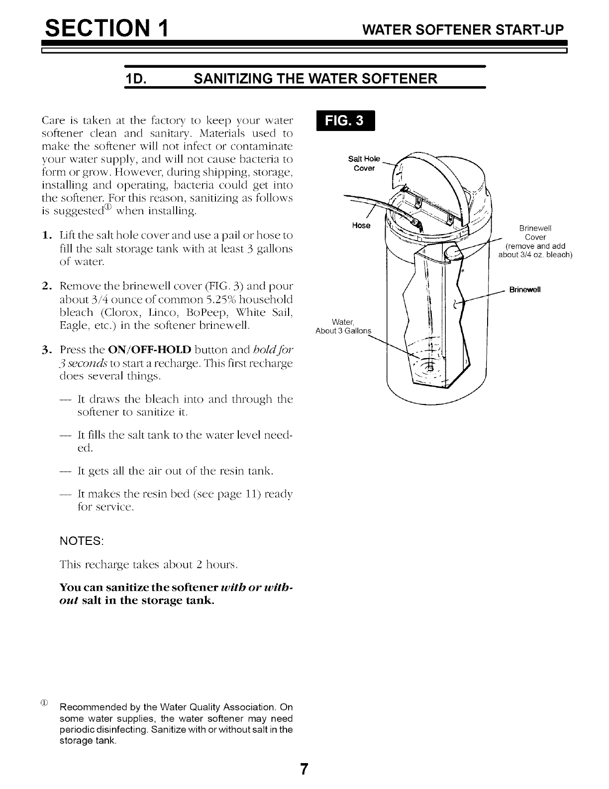
1. Lift the salt hole cover and use a pail or hose to
fill the salt storage tank with at least 3 gallons
of water.
oRemove the bfinewell cover (FIG. 3) and pour
about 3/4 ounce of common 5.25% household
bleach (Clorox, Linco, BoPeep, White Sail,
Eagle, etc.) in the softener brinewell.
oPress the ON/OFF-HOLD button and bold fi)r
3 secomls to start a recharge. This first recharge
does several things.
-- It draws the bleach into and through the
softener to sanitize it.
-- It fills the salt tank to the water level need-
ed.
-- It gets all the air out of the resin tank.
-- It makes the resin bed (see page 11) ready
for service.
Salt Hole
Cover
Hose
Water,
About 3 Gallons
Brinewell
Cover
(remove and add
about 3/4 oz. bleach)
Brinewell
NOTES:
This recharge takes about 2 hours.
You can sanitize the softener with or with-
out salt in the storage tank.
Recommended by the Water Quality Association. On
some water supplies, the water softener may need
periodic disinfecting. Sanitize with or without salt in the
storage tank.
7
SECTION 1 WATER SOFTENER START-UP
1E. FILL THE STORAGE TANK WITH SALT
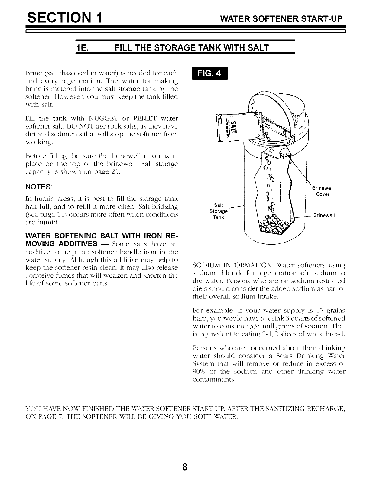
Brine (salt dissolved in wateO is needed fi)r each
and every regeneration. The water fi)r making
brine is metered into the salt storage tank by the
softener. However, you must keep the tank filled
with salt.
Fill the tank with NUGGET or PELLET water
softener salt. DO NOT use rock salts, as they have
dirt and sediments that will stop the softener from
working.
Before filling, be sure the brinewell cover is in
place on the top of the brinewen. Salt storage
capacity is shown on page 21.
NOTES:
In humid areas, it is best to fill the storage tank
half-full, and to refill it more often. Salt bridging
(see page 14) occurs more often when conditions
are humid.
WATER SOFTENING SALT WITH IRON RE-
MOVING ADDITIVES -- Some salts have an
additive to help the softener handle iron in the
water supply. Although this additive may hel t) to
keep the softener resin clean, it may also release
corrosive fumes that will weaken and shorten the
life of some softener parts.
<A
j_
sto_g_ \ JZI !\ I
Tank
Brinewell
Cover
Brinewell
SODIITM INFORMATION: Water softeners using
sodium chloride for regeneration add sodium to
the water. Persons who are on sodium restricted
diets should consider the added sodium as part of
their overall sodium intake.
For example, if your water supply is 15 grains
hard, you would have to drink 3 quarts of softened
water to consume 335 milligrams of sodium. That
is equivalent to eating 2-1/2 slices of white bread.
Persons who are concerned about their drinking
water should consider a Sears Drinking Water
System that will remove or reduce in excess of
90% of the sodium and other drinking water
contaminants.
YOU HAVE NOW FINISHED THE WATER SOFTENER START UP. AFTER THE SANITIZING RECHARGE,
ON PAGE 7, THE SOFTENER WILL BE GIVING YOU SOFT WATER.
8
SECTION 2 HOW YOUR WATER SOFTENER WORKS
I
2A. FACE PLATE TIMER FEATURES
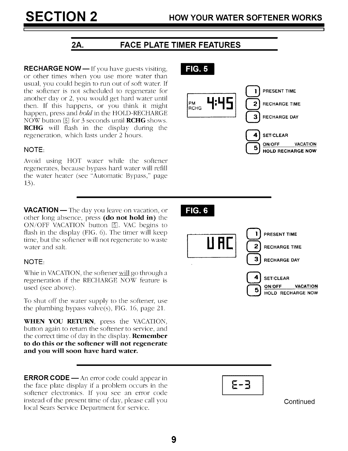
RECHARGE NOW-- If you have guests visiting,
or other times when you use n]ore water than
usual, you could begin to run out of soft water. If
the softener is not scheduled to regenerate for
another day or 2, you would get hard water until
then. If this happens, or you think it might
happen, press and hold in the HOLD-RECHARGE
NOW button [] for 3 seconds until RCHG shows.
RCHG will flash in the display during the
regeneration, which lasts under 2 hours.
NOTE:
Avoid using HOT water while the softener
regenerates, because bypass hard water will refill
the water heater (see "Automatic Bypass," page
13).
PRESENT TIME
RECHARGE TIME
RECHARGE DAY
_SET!CLEAR
QON/OFF VACATION
HOLD RECHARGE NOW
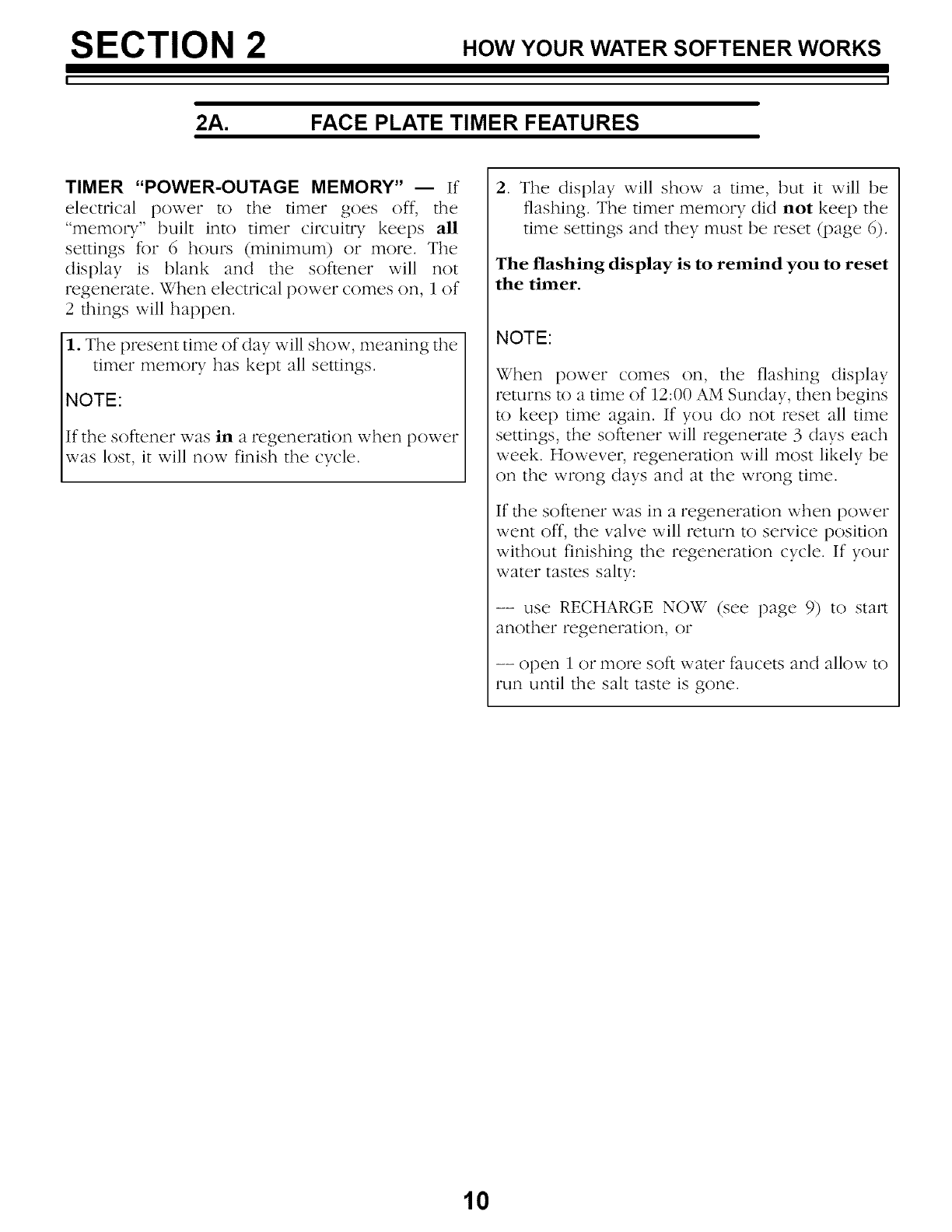
VACATION -- The day you leave on vacation, or
other long absence, press (do not hold in) the
ON/OFF VACATION button []. VAC begins to
flash in the display (FIG. 6). The timer will keel)
time, but the softener will not regenerate to waste
water and salt.
NOTE:
Whie in VACATION, the softener will go through a
regeneration if the RECHARGE NOW feature is
used (see above).
To shut off the water supply to the softener, use
the plumbing bypass valve(s), FIG. 16, page 21.
WHEN YOU RETURN, press the VACATION,
button again to return the softener to service, and
the correct time of day in the display. Remember
to do this or the softener will not regenerate
and you will soon have hard water.
IIJFI[ QPRESENT TIME
QRECHARGE TIME
GRECHARGE DAY
SET/CLEAR
QON'OFF VACATION
HOLD RECHARGE NOW
ERROR CODE -- An error code could appear in
the face plate display if a problem occurs in the
softener electronics. If you see an error code
instead of the present time of day, please call you
local Sears Service Department for service.
';_-3
Continued
9
SECTION 2 HOW YOUR WATER SOFTENER WORKS
2A. FACE PLATE TIMER FEATURES
TIMER "POWER-OUTAGE MEMORY" -- If
electrical power to the timer goes off, the
"memory" built into timer circuitry keeps all
settings f_)r 6hours (minimun 0 or more. The
display is blank and the softener will not
regenerate. When electrical power comes on, i of
2 things will happen.
1. The present time of day will show, meaning the
timer memory has kept all settings.
NOTE:
If the softener was in a regeneration when power
was lost, it will now finish the cycle.
2. The display will show a time, but it will be
flashing. The timer memory did not keel) the
time settings and they must be reset (page 6).
The flashing display is to remind you to reset
the timer.
NOTE:
When power comes on, the flashing display
returns to a time of 12:00 AM Sunday, then begins
to keel) time again. If you do not reset all time
settings, the softener will regenerate 3 days each
week. However, regeneration will most likely be
on the wrong days and at the wrong time.
If the softener was in a regeneration when power
went off, the valve will return to service position
without finishing the regeneration cycle. If your
water tastes salty:
-- use RECHARGE NOW (see page 9) to start
another regeneration, or
-- open 1 or illor{2soft water faucets and allow tO
run until the salt taste is gone.
10
SECTION 2 HOW YOUR WATER SOFTENER WORKS
I
2B. SOFTWATER SERVICE AND REGENERATION
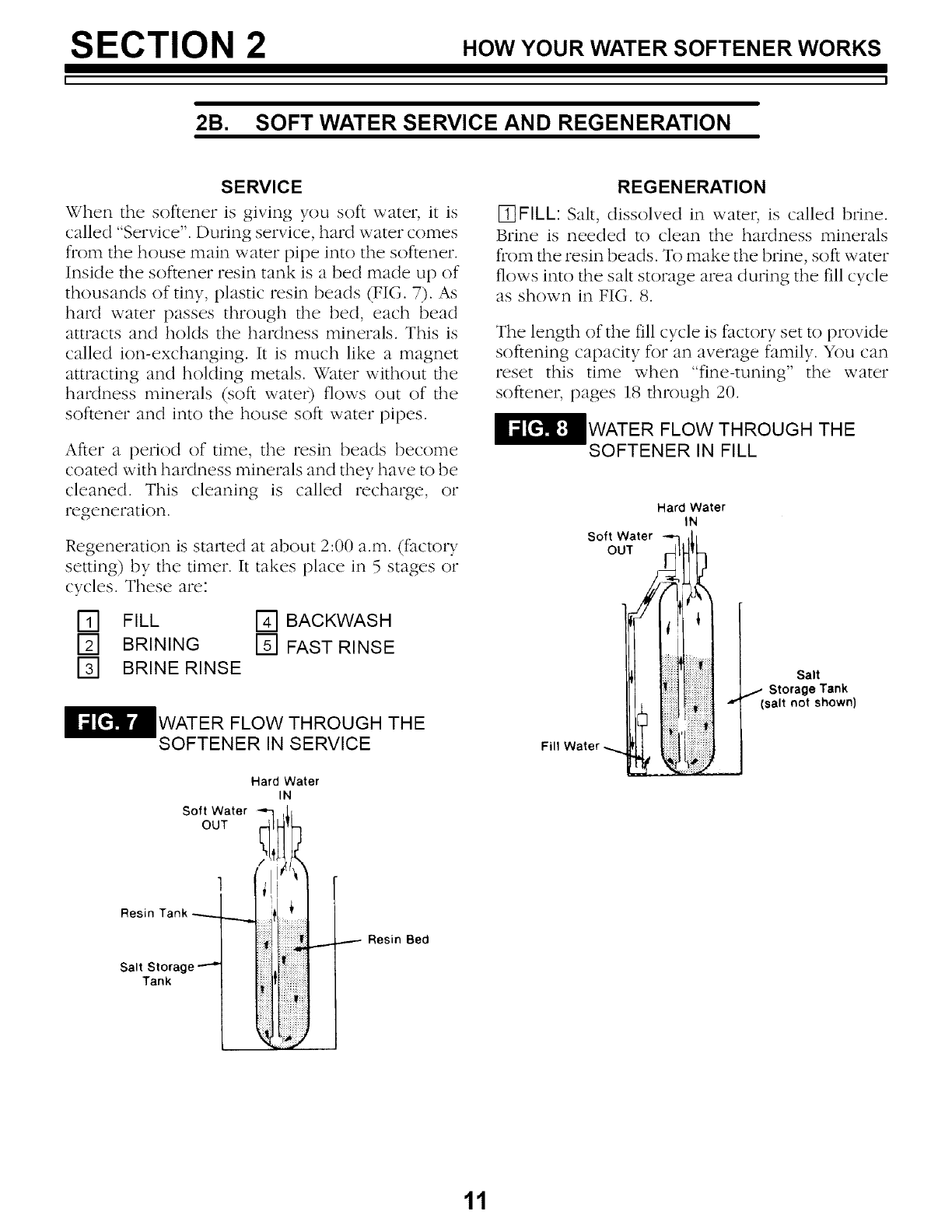
SERVICE
When the softener is giving you soft water, it is
called "Service". During service, hard water comes
from the house main water pipe into the softener.
Inside the softener resin tank is a bed made up of
thousands of tiny, plastic resin beads (FIG. 7). As
hard water passes through the bed, each bead
attracts and holds the hardness minerals. This is
called ion-exchanging. It is much like a magnet
attracting and holding metals. Water without the
hardness minerals (soft water) flows out of the
softener and into the house soft water pipes.
After a period of time, the resin beads become
coated with hardness minerals and they have to be
cleaned. This cleaning is called recharge, or
regeneration.
Regeneration is stinted at about 2:00 a.m. (factory
setting) by the timer. It takes place in 5 stages or
cycles. These are:
E_ FILL
[] BRINING
[] BRINE RINSE
BACKWASH
[] FAST RINSE
WATER FLOW THROUGH THE
SOFTENER IN SERVICE
Hard Water
IN
Soft Water
OUT
REGENERATION
%FILL: Salt, dissolved in water, is called brine.
Brine is needed to clean the hardness minerals
from the resin beads. To make the brine, soft water
flows into the salt storage area during the fill cycle
as shown in FIG. 8.
The length of the fill cycle is factory set to provide
softening capacity for an average family. You can
reset this time when "fine-tuning" the water
softener, pages 18 through 20.
WATER FLOW THROUGH THE
SOFTENER IN FILL
Hard Water
IN
Soft Water ,/-
OUt _k
.... storaS";'Tao
Fill Water -_ l I
__J
Resin
Salt Storage
Tank
...--- Resin Bed
11
SECTION 2 HOW YOUR WATER SOFTENER WORKS
2B. SOFT WATER SERVICE AND REGENERATION
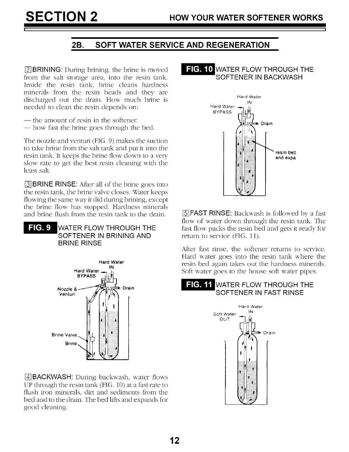
[] BRINING: During brining, the brine is moved
from the salt storage area, into the resin tank.
Inside the resin tank, brine cleans hardness
minerals from the resin beads and they are
discharged out the drain. How much brine is
needed to clean the resin depends on:
-- the amount of resin in the softener.
-- how fast the brine goes through the bed.
The nozzle and venturi (FIG. 9) makes the suction
to take brine fi'om the salt tank and put it into the
resin tank. It keeps the brine flow down to a very
slow rate to get the best resin cleaning with the
least salt.
[3-]BRINE RINSE: After all of the brine goes into
the resin tank, the brine valve closes. Water keeps
flowing the same way it did during brining, except
the brine flow has stopped. Hardness minerals
and brine flush from the resin tank to the drain.
WATER FLOW THROUGH THE
SOFTENER IN BRINING AND
BRINE RINSE
Hard Water
IN
Hard Water.
Nozzle Drain
Venturi
Brine Valve
Brine
I_]BACKWASH: During backwash, water flows
UP through the resin tank (FIG. 10) at a fast rate to
flush iron minerals, dilx and sediments from the
bed and to the drain. The bed lifts and expands for
good cleaning.
WATER FLOW THROUGH THE
SOFTENER IN BACKWASH
Hard Water
IN
Hard Water
BYPASS
Drain
bee
and expa
[]FAST RINSE: Backwash is fbllowed by a fast
flow of water down through the resin tank. The
fast flow packs the resin bed and gets it ready for
return to service (FIG. 11).
After fast rinse, the softener returns to service.
Hard water goes into the resin tank where the
resin bed again takes out the hardness minerals.
Soft water goes to the house soft water pipes.
WATER FLOW THROUGH THE
SOFTENER IN FAST RINSE
Hard Waler
IN
Soft Water
OUT _-_1 _f ii3i" Drain
12
SECTION 2 HOW YOUR WATER SOFTENER WORKS
J
2B. SOFT WATER SERVICE AND REGENERATION
AUTOMATIC BYPASS
During the brining, brine rinse and backwash
cycles of regeneration, HARD water goes through
the softener valve and to the house pipes. If a
faucet is opened, hard water is there for your
needs. However, you should not use HOT water, if
possible, because the water heater will refill with
hard water. The softener regenerates from 2:00
AM to about 4:00 AM, (you can set anytime), a time
when not much water is used.
If you get up early in the morning and you can
hear the softener regenerating, change the time
setting. Set the recharge time to 12:00 AM or 1:00
AiM (page 18). Then regeneration will start and
end that much earlier and your water heater will
not refill with hard water if a hot faucet is opened.
13
SECTION 3 CARE OF YOUR SOFTENER
I l
3A. SALT...REFILLING STORAGE TANK/BREAKING A SALT BRIDGE
WHEN TO REFILI. WITH SALT: Check the salt
level a few weeks after you install the softener and
every week after that. Refill when the storage
tank is about 1/3 full. Never let the softener use
fill the salt before refilling. Without salt, you will
soon have hard water.
IMPORTANT:
YOU will have a loss in softening capacity and
may get partly hard water if less than 10
inches of salt is in the storage tank.
PLEASE SEE PAGE 8 FOR SALT FILLING DIRECTIONS.
SALT BRIDGE
Sometimes, a hard crust or salt bridge forms in the
salt storage tank. It is usually caused by iaigia
humidity or the wrong kind of salt. When the salt
bridges, an empty space forms between the water
find salt. Then, salt will not dissolve (melt) in the
water to make brine. Without brine, the resin bed
does not regenerate and you will have haM water.
If the storage tank is full of salt, it is hard to tell if
you have a salt bridge. Salt is loose on top, but the
bridge is under it. The following is the best way to
check for a salt bridge.
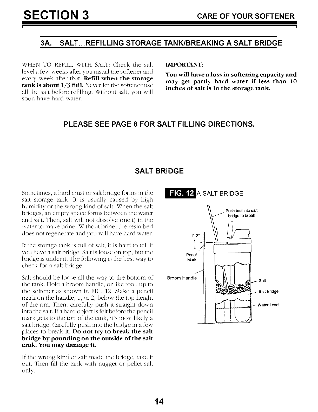
Salt should be loose all the way to the bottom of
the tank. Hold a broom handle, or like tool, up to
the softener as shown in FIG. 12. Make a pencil
mark on the handle, 1, or 2, below the top height
of the rim. Then, carefully push it straight down
into the salt. If a hard object is felt before the pencil
mark gets to the top of the tank, it's most likely a
salt bridge. Carefully push into the bridge in a few
places to break it. Do not try to break the salt
bridge by pounding on the outside of the salt
tank. You may damage it.
If the wrong kind of salt made the bridge, take it
out. Then fill the tank with nugget or pellet salt
only.
t__
Pencil
Mark
Broom Handle
A SALT BRIDGE
b PbrSh;°tloibtr°eSkIt
-@
I- Salt
I _ .I Salt Bridge
[_ ,__ _ Water Level
14
SECTION 3 CARE OF YOUR SOFTENER
3B. KEEPING THE WATER SOFTENER CLEAN
COVERS
To keep your new Sears water softener looking
nice, apply a coat of paste wax and repeat once a
year. When dusty, wipe it with a damp cloth to
keep it sparkling.
NOTE:
Never use cleaners having aFtlFFtonia or abrasives.
They may scratch and dull the surface.
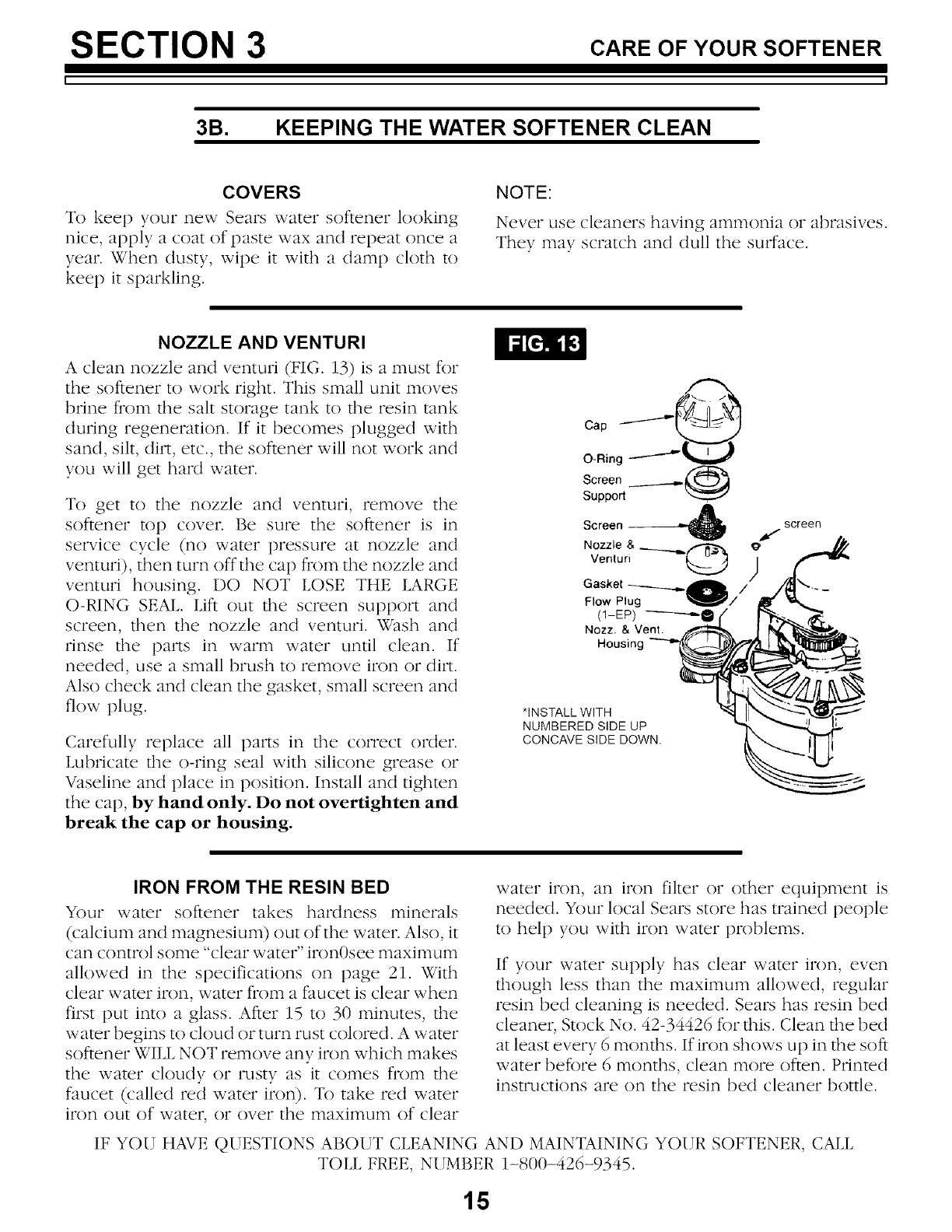
NOZZLE AND VENTURI
A clean nozzle and venturi (FIG. 13) is a must for
the softener to work right. This small unit moves
brine t'rom the salt storage tank to the resin tank
during regeneration. If it becomes plugged with
sand, silt, dirt, etc., the softener will not work and
you will get haM water.
To get to the nozzle and venturi, remove the
softener top cover. Be sure the softener is in
service cycle (no water pressure at nozzle and
venturi), then turn off the cap from the nozzle and
venturi housing. DO NOT LOSE THE lARGE
O-RING SEAL. Lift out the screen support and
screen, then the nozzle and venturi. Wash and
rinse the parts in warm water until clean. If
needed, use a small brush to remove iron or dirt.
Also check and clean the gasket, small screen and
flow plug.
Carefully replace all pm_s in the correct order.
Lubricate the o-ring seal with silicone grease or
Vaseline and place in position. Install and tighten
the cap, by hand only. Do not overtighten and
break the cap or housing.
*INSTALL WITH
NUMBERED SIDE UP
CONCAVE SIDE DOWN.
screen
)
IRON FROM THE RESIN BED
Your water softener takes hardness minerals
(calcium and magnesium) out of the water. Also, it
can control some "clear water" iron0see maximunl
allowed in the specifications on page 21. With
clear water iron, water from a faucet is clear when
first put into a glass. After 15 to 30 minutes, the
water begins to cloud or turn rust colored. A water
softener WILL NOT remove any iron which makes
the water cloudy or rusty as it comes fl'om the
faucet (called red water iron). To take red water
iron out of water, or over the maximum of clear
water iron, an iron filter or other equipment is
needed. Your local Sears store has trained people
to help you with iron water problems.
If your water supply has clear water iron, even
though less than the maximum allowed, regular
resin bed cleaning is needed. Sears has resin bed
cleaner, Stock No. 42-34426 for this. Clean the bed
at least every 6 months. If iron shows up in the soft
water before 6 months, clean more often. Printed
instructions are on the resin bed cleaner bottle.
IF YOU HAVE QUESTIONS ABOUT CLEANING AND MAINTAINING YOUR SOFTENER, CALL
TOLL FREE, NUMBER 1-800-426-9345.
15
SECTION 3 CARE OF YOUR SOFTENER
3C. KEEP THE SOFTENER FROM FREEZING
If the softener is installed where it could freeze
(summer cabin, lake home, etc.), you rnust drain
all water from it to stop possible freeze damage.
To drain the softener-
1. Close the shut-off valve on the house main
water pipe, near the water meter or pressure
tank.
2. Open a faucet in the soft water pipes to vent
pressure in the softener.
.I.ooking at FIG. 16 on [)age 21, move the stem
in a single bypass valve to bypass. Close the
inlet and outlet valve in a 3-valve bypass
system, and open the bypass valve. If you want
water in the house pipes again, reopen the
shut-off valve on the main water pipe.
4. Unplug the transformer at the wall outlet.
Remove the salt hole cover and the main
cover. Take off"both drain hoses.
.Carefully remove the large holding clips at the
softener inlet and outlet (see Key No. 61, on
page 34). Separate the softener from the
adaptors or bypass valve.
°Remove the brinewen cover and disconnect
the brine valve tubing at the nozzle and venturi
assembly (see page 34). Liftthe brine valve out
of the brinewell. Tip the brine valve upside
down to drain out water.
DRAIN WATER FROM THE
SOFTENER
Drain Wood Block
.
°
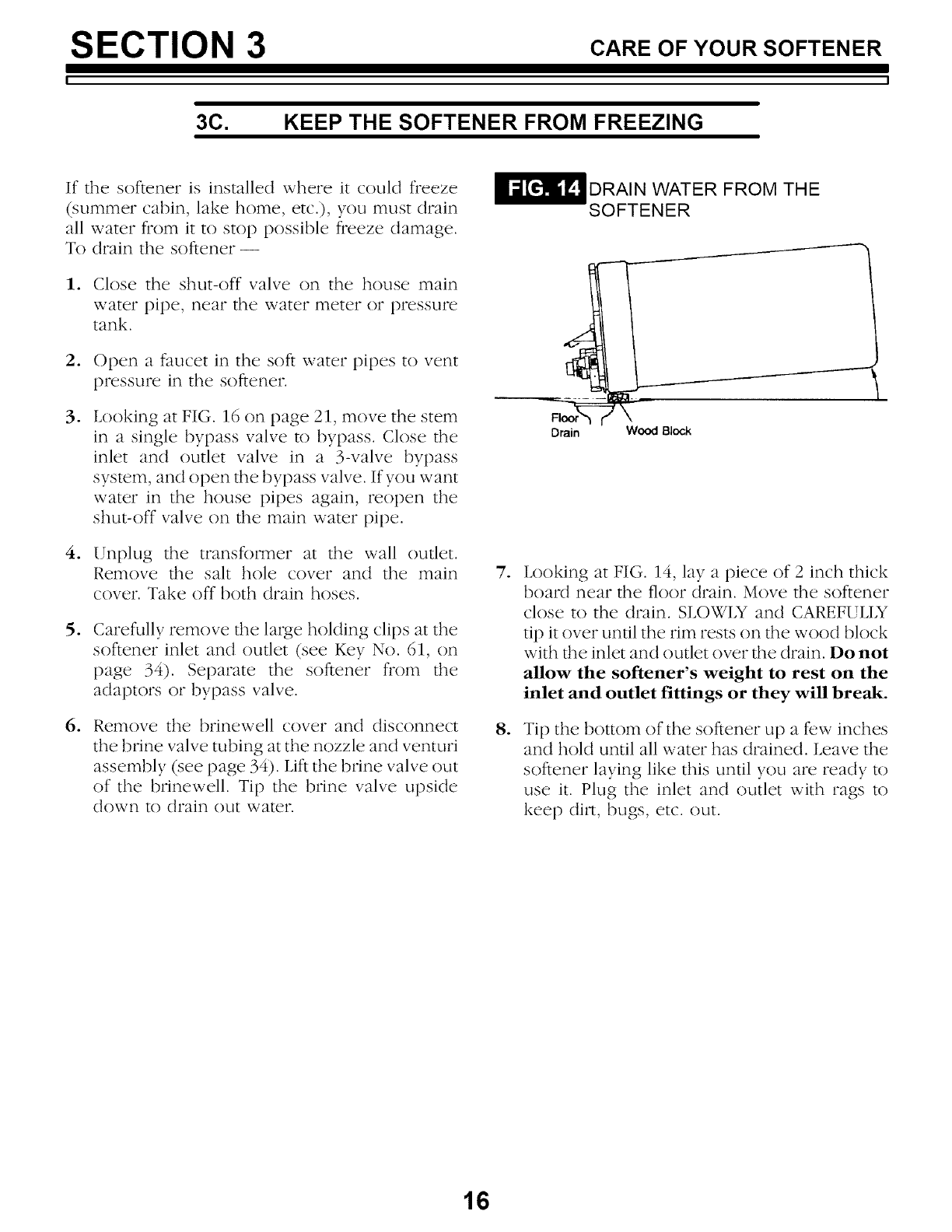
Looking at FIG. 14, lay a piece of 2 inch thick
board near the floor drain. Move the softener
close to the drain. SLOWIX and CAREFULIX
tip it over until the rim rests on the wood block
with the inlet and outlet over the drain. Do not
allow the softener's weight to rest on the
inlet and outlet fittings or they will break.
Tip the bottom of the softener up a few inches
and hold until all water has drained. Leave the
softener laying like this until you are ready to
use it. Plug the inlet and outlet with rags to
keep dilx, bugs, etc. out.
16
SECTION 3 CARE OF YOUR SOFTENER
3D. HELPFUL HINTS CHECKLIST
... TO HELP YOU SAVE MONEY
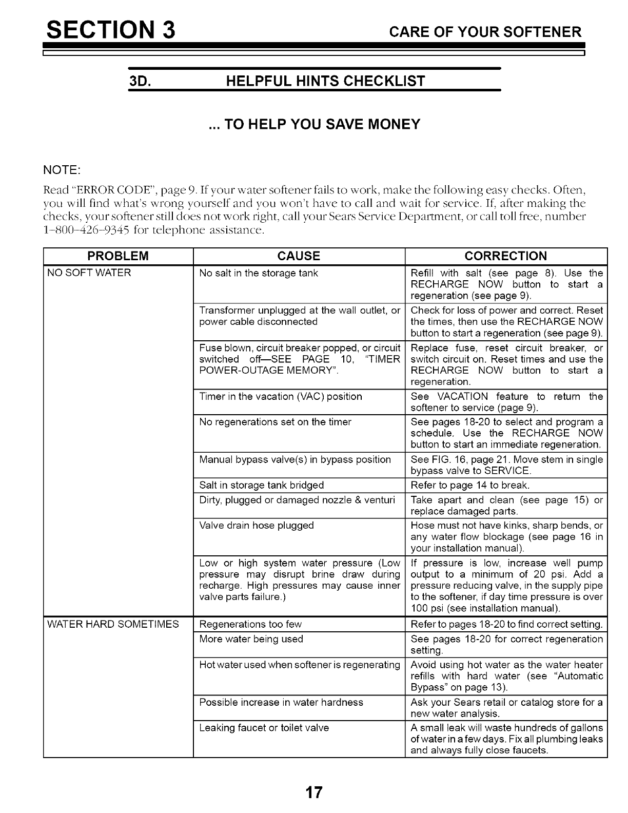
NOTE:
Read "ERROR CODE", page 9. If your water softener fails to work, make the following easy checks. Often,
you will find what's wrong yourself and you won't have to call and wait for service. If, after making the
checks, your softener still does not work right, call your Sears Service Department, or call ton flee, number
1-800-426-9345 for telephone assistance.
PROBLEM CAUSE CORRECTION
NO SOFT WATER No salt in the storage tank
WATER HARD SOMETIMES
Transformer unplugged at the wall outlet, or
power cable disconnected
Fuse blown, circuit breaker popped, or circuit
switched off--SEE PAGE 10, "TIMER
POWER-OUTAGE MEMORY".
Timer in the vacation (VAC) position
No regenerations set on the timer
Manual bypass valve(s) in bypass position
Salt in storage tank bridged
Dirty, plugged or damaged nozzle & venturi
Valve drain hose plugged
Low or high system water pressure (Low
pressure may disrupt brine draw during
recharge. High pressures may cause inner
valve parts failure.)
Regenerations too few
More water being used
Hot water used when softener is regenerating
Possible increase in water hardness
Leaking faucet or toilet valve
Refill with salt (see page 8). Use the
RECHARGE NOW button to start a
regeneration (see page 9).
Check for loss of power and correct. Reset
the times, then use the RECHARGE NOW
button to start a regeneration (see page 9).
Replace fuse, reset circuit breaker, or
switch circuit on. Reset times and use the
RECHARGE NOW button to start a
regeneration.
See VACATION feature to return the
softener to service (page 9).
See pages 18-20 to select and program a
schedule. Use the RECHARGE NOW
button to start an immediate regeneration.
See FIG. 16, page 21. Move stem in single
bypass valve to SERVICE
Refer to page 14 to break.
Take apart and clean (see page 15) or
replace damaged parts.
Hose must not have kinks, sharp bends, or
any water flow blockage (see page 16 in
your installation manual).
If pressure is low, increase well pump
output to a minimum of 20 psi. Add a
pressure reducing valve, in the supply pipe
to the softener, if day time pressure is over
100 psi (see installation manual).
Refer to pages 18-20 to find correct setting.
See pages 18-20 for correct regeneration
setting.
Avoid using hot water as the water heater
refills with hard water (see "Automatic
Bypass" on page 13).
Ask your Sears retail or catalog store for a
new water analysis.
A small leak will waste hundreds of gallons
of water in a few days. Fix all plumbing leaks
and always fully close faucets.
17
SECTION 4 OT.ERT.,NGSTOKNOW
4A. HOW TO "FINE-TUNE" YOUR SOFTENER
It is not ham to fine-tune your softener, but it does
take a few minutes of your time to do it right. You
may save up to 500 pounds or more of salt each
year with proper tuning. Read the following
carefully.
To have soft water all the time, the softener must
regenerate, or recharge a certain number of times
in each 7 day period. How many times to
regenerate (set the timer) depends on 3 things.
1. The number of people in your home -- tells
you how much water is used.
oThe grains per gallon (GPG) hardness of your
water supply -- listed on your water analysis
report (see page 2 in your Installation Manual,
or page 2 of this manual).
NOTE:
If your water supply contains iron, compensate for
it by adding to the water hardness number. For
examp& assume your water is 15 gpg hard and
contains 2 ppm h'on. Add 5 to the hardness
number fi)r each 1 ppm o/'h'on. In this example,
you would use 25 jbr yom" haMness numbeJ:
15 gpg hardness
2 ppm iron x5 = 10 +10
(times) 25 HARDNESS NUMBER
3. How much salt is used each regeneration --
determined by the length of the fill cycle (see
pages 19 and 20).
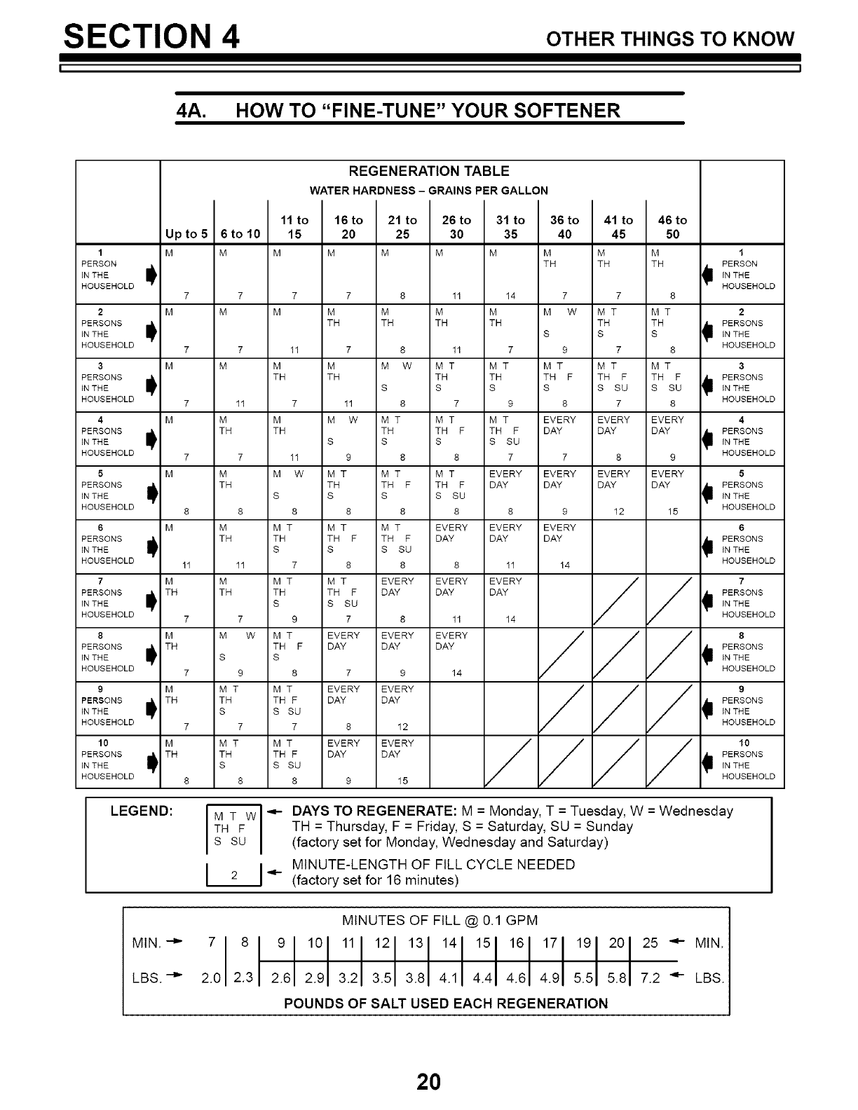
REGENERATION TABLE: The table (page 20)
makes it easy fo you to pick the best regeneration
and fill time setting to use.
Step 1 -- Go down the side of the table to the
number of persons in your family, or the number
of people in the house using water.
Step 2 -- Across the top of the table, find the
column listing the grains per gallon hardness of
your water, or hardness number for iron water.
Step 3 -- Read across and down the table to find
the point where steps 1 and 2 meet. At this
meeting point, suggested days to regenerate, and
fill cycle minutes needed are shown.
TO SET THE TIMER FOR DAYS OF REGEN-
ERATION AND FILL MINUTES, DO THE FOL-
LOWING.
NOTE:
Remember, the timer is factory set for Monday,
Wednesday and Saturday regenerations starting at
2:00 AM. Fill time is factory set for 16 minutes.
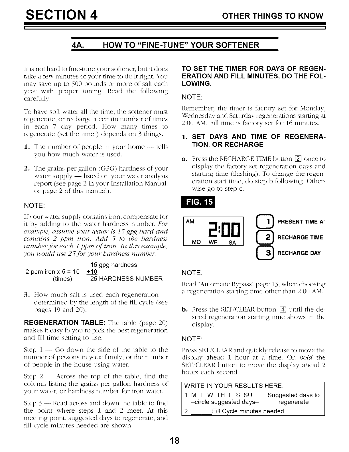
1. SET DAYS AND TIME OF REGENERA-
TION, OR RECHARGE
ao Press the RECHARGE TIME button [] once to
display the factory set regeneration days and
stm_ing time (flashing). To change the regen-
eration start time, do step b following. Other-
wise go to step c.
AM 2:00
MO WE SA
QPRESENT TIME A'
RECHARGE TIME
RECHARGE DAY
NOTE:
Read "Automatic Bypass" page 13, when choosing
a regeneration starting time other than 2:00 AM.
b. Press the SET/CLEAR button [] until the de-
sired regeneration starting time shows in the
display.
NOTE:
Press SET/CLEAR and quickly release to move the
display ahead 1 hour at a time. Or, hold the
SET/CLEAR button to move the display ahead 2
hours each second.
WRITE IN YOUR RESULTS HERE.
1.M T W TH F S SU Suggested days to
-circle suggested days- regenerate
2. Fill Cycle minutes needed
18
SECTION 4 OTHERTH,NGSTOKNOW
ij
4A. HOW TO "FINE-TUNE" YOUR SOFTENER
c. Press the RECHARGE DAY button [] and
SUnday begins to flash.
-- If you z_,al_l regenerations on Sunday (from
regeneration table), press the SET/CLEAR button
[] to display ON.
-- If you do l_ot wal_l Sunday regenerations, press
SET/CLEAR button [] to display OFF.
do Press the RECHARGE DAY button [] again to
display a flashing MOnday and ON (factory set
recharge). As you did in step c, use the SET/
CLEAR button [] to change the display from
ON to OFF, or from OFF to ON.
eo Press RECHARGE DAY button [] to display a
flashing TUesday, WEdnesday, etc., each time
using the SET/CLEAR button [] to display ei-
ther ON or OFF as needed.
After recharge is either set or cancelled for SAt-
urday, press the PRESENT TIME AND DAY
button [] once again to return the present
time and day display.
2. SET THE FILL CYCLE MINUTES
ao
bo
Press and hold the RECHARGE TIME button
[] until FILLshows in the display, then release
button []. After a few seconds, the fill cycle
minutes (factory setting... 16) will flash.
Press the SET/CLEAR button [] to set the min-
utes of fill cycle needed, as shown in the re-
generation table.
NOTE:
You may get hard water between regenerations if
you set the timer for fewer fill minutes than the
Regeneration Table shows you to set. A higher
setting than needed will waste salt.
NOTE:
Press SET/CLEAR and quickly release to move the
display ahead 1 minute at a time. Or, hold the
SET/CLEAR button to move the display ahead 2
minutes each second. THE DISPLAY BEGINS
OVER AT 0 AFTER PASSING 59.
c. Press PRESENT TIME AND DAY button [] to
return the present time and day display.
TO SET THE PRESENT TIME OF DAY, AND DAY
OF WEEK, SEE PAGE 6.
IF YOU NEED HELP TO PROGRAM THE TIMER, CALL TOLL FREE,
NUMBER 1-800- 426-9345.
19
SECTION 4 OTHERTH,NGSTOKNOW
4A. HOW TO "FINE-TUNE" YOUR SOFTENER
1
PERSON
IN THE I
HOUSEHOLD
2
PERSONS I
IN THE
HOUSEHOLD
3
PERSONS I
IN THE
HOUSEHOLD
4 M
PERSONS I
IN THE
HOUSEHOLD
5 M
PERSONS I
IN THE
HOUSEHOLD
6 M
PERSONS iIN THE
HOUSEHOLD
7 M
PERSONS I THIN THE
HOUSEHOLD
8 M
PERSONS I THIN THE
HOUSEHOLD
9 M
PERSONS I THIN THE
HOUSEHOLD
10 M
PERSONS I TH
IN THE
HOUSEHOLD
LEGEND:
REGENERATION TABLE
Upto5 6to10
M M
WATER HARDNESS- GRAINS PER GALLON
11 to 16to 21 to 26to 31 to 36 to 41 to 46to
15 20 25 30 35 40 45 50
M M M M M M M M
TH TH TH
7 7 7 7 8 11 14 7 7 8
1
PERSON
_ IN THE
HOUSEHOLD
M M M M M M M W MT MT 2
TH TH TH TH TH TH AI_ PERSONS
S S S _ IN THE
HOUSEHOLD
7 7 11 7 8 11 7 9 7 8
M M M M W MT MT MT MT MT 3
TH TH TH TH TH F TH F TH F _1= PERSONS
S S S S S SU S SU _ IN THE
7 11 7 11 8 7 9 8 7 8 HOUSEHOLD
M M M W M T M T M T EVERY EVERY EVERY 4
TH TH TH TH F TH F DAY DAY DAY _1. PERSONS
S S S S SU _ IN THE
7 11 9 8 8 7 7 8 9 HOUSEHOLD
M M W M T M T M T EVERY EVERY EVERY EVERY 5
TH TH TH F TH F DAY DAY DAY DAY _lu PERSONS
S S S S SU _ IN THE
8 8 8 8 8 8 9 12 15 HOUSEHOLD
M MT MT MT
TH TH TH F TH F
S S S SU
11 7 8 8
M M T M T EVERY
TH TH TH F DAY
S S SU
7 9 7 8
M W M T EVERY EVERY
TH F DAY DAY
S S
9 8 7 9
M T M T EVERY EVERY
TH TH F DAY DAY
S S SU
7 7 8 12
M T M T EVERY EVERY
TH TH F DAY DAY
S S SU
8 8 9 15
EVERY EVERY EVERY 6
DAY DAY DAY AI_ PERSONS
IN THE
8 11 14 HOUSEHOLD
EVERY EVERY / / i7
DAY DAY PERSONS
IN THE
14 HOUSEHOLD
///, .
PERSONS
IN THE
HOUSEHOLD
///, PERSONS
IN THE
HOUSEHOLD
////, PERSONS
iN THE
HOUSEHOLD
11
EVERY
DAY
14
.,t- AYS TO REGENERATE: M = Monday, T = Tuesday, W = Wednesday
TH = Thursday, F = Friday, S = Saturday, SU = Sunday
(factory set for Monday, Wednesday and Saturday)
21 MINUTE-LENGTH OF FILL CYCLE NEEDED
(factory set for 16 minutes)
MINUTES OF FILL @ 0.1 GPM
:oLL::::: ::: 4.4 14. 1 14. 71
POUNDS OF SALT USED EACH REGENERATION
20
SECTION 4 OTHERTH,NGSTOKNOW
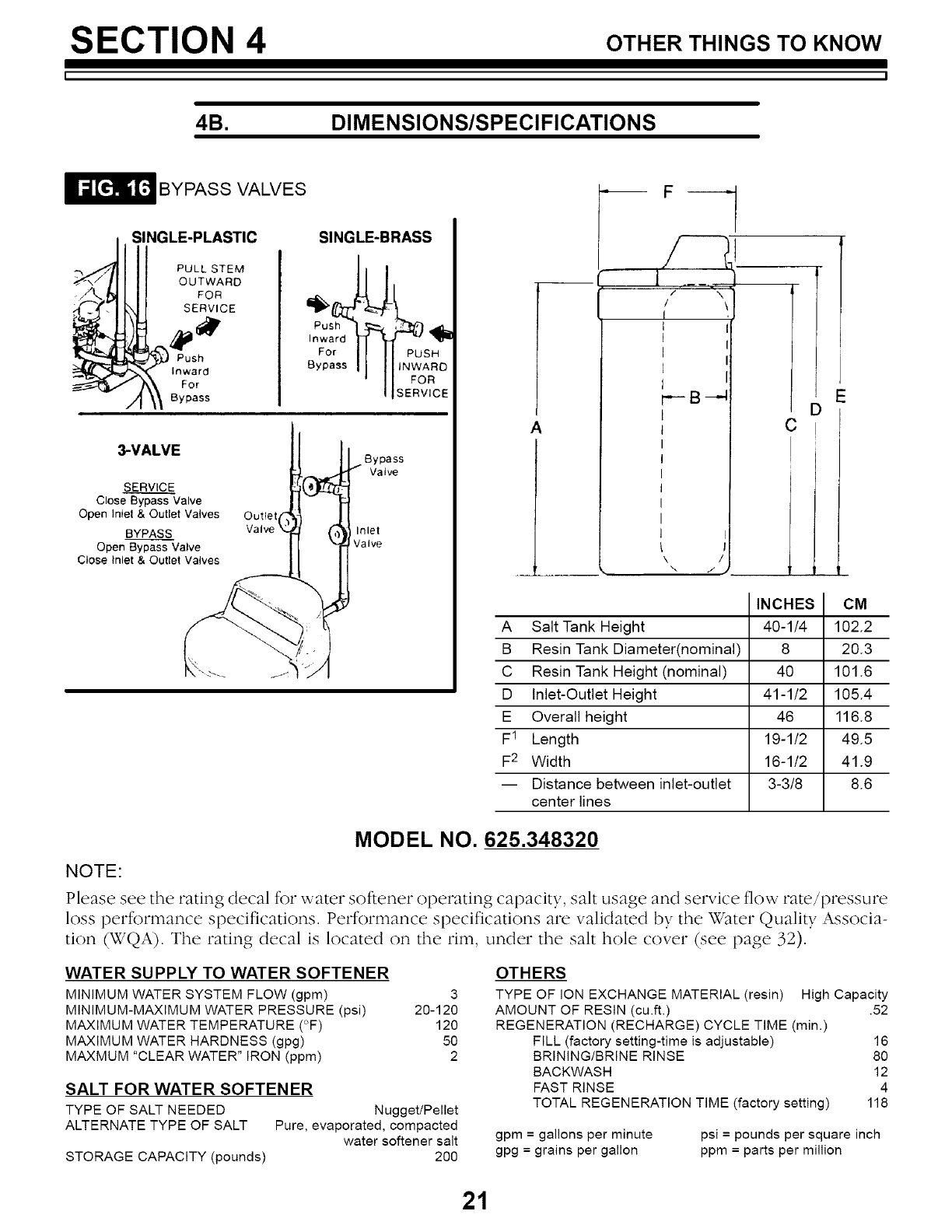
4B. DIMENSIONS/SPECIFICATIONS
BYPASS VALVES
SINGLE-PLASTIC
PULL STEM
OUTWARD
FOR
SERVICE
SINGLE-BRASS
For SH
Bypass I tNWARD
I FOR
ISERVICE
3-VALVE
SERVICE_
Close Bypass Valve
Open Intet& Outlet Valves
BYPASS
Open Bypass Valve
Close Inlet & Outlet Valves
Outlet
Bypass
Valve
Inlet
Valve
A
1
/N
/\
I
_B_
\/
\ J
INCHES CM
A Salt Tank Height 40-1/4 102.2
B Resin Tank Diameter(nominal) 8 20.3
C Resin Tank Height (nominal) 40 101.6
D Inlet-Outlet Height 41-1/2 105.4
E Overall height 46 116.8
F 1 Length 19-1/2 49.5
F2 Width 16-1/2 41.9
-- Distance between inlet-outlet 3-3/8 8.6
center lines
MODEL NO. 625.348320
NOTE:
Please see the rating decal t_>r water softener operating capacity, salt usage and service flow rate/pressure
loss performance specifications. Performance specifications arc validated by the Water Quality Associa-
tion (WQA). The rating decal is located on the rim, under the salt hole cover (see page 32).
WATER SUPPLY TO WATER SOFTENER
MINIMUM WATER SYSTEM FLOW (gpm) 3
MINIMUM-MAXIMUM WATER PRESSURE (psi) 20-120
MAXIMUM WATER TEMPERATURE (°F) 120
MAXIMUM WATER HARDNESS (gpg) 50
MAXMUM "CLEAR WATER" IRON (ppm) 2
SALT FOR WATER SOFTENER
TYPE OF SALT NEEDED Nugget/Pellet
ALTERNATE TYPE OF SALT Pure, evaporated, compacted
water softener salt
STORAGE CAPACITY (pounds) 200
OTHERS
TYPE OF ION EXCHANGE MATERIAL (resin) High Capacity
AMOUNT OF RESIN (cu.ft.) .52
REGENERATION (RECHARGE) CYCLE TIME (min.)
FILL (factory setting-time is adjustable) 16
BRINING/BRINE RINSE 80
BACKWASH 12
FAST RINSE 4
TOTAL REGENERATION TIME (factory setting) 118
gpm = gallons per minute
gpg = grains per gallon
psi = pounds per square inch
ppm = parts per million
21
SECTION 5 SERVICE TECH. INFORMATION
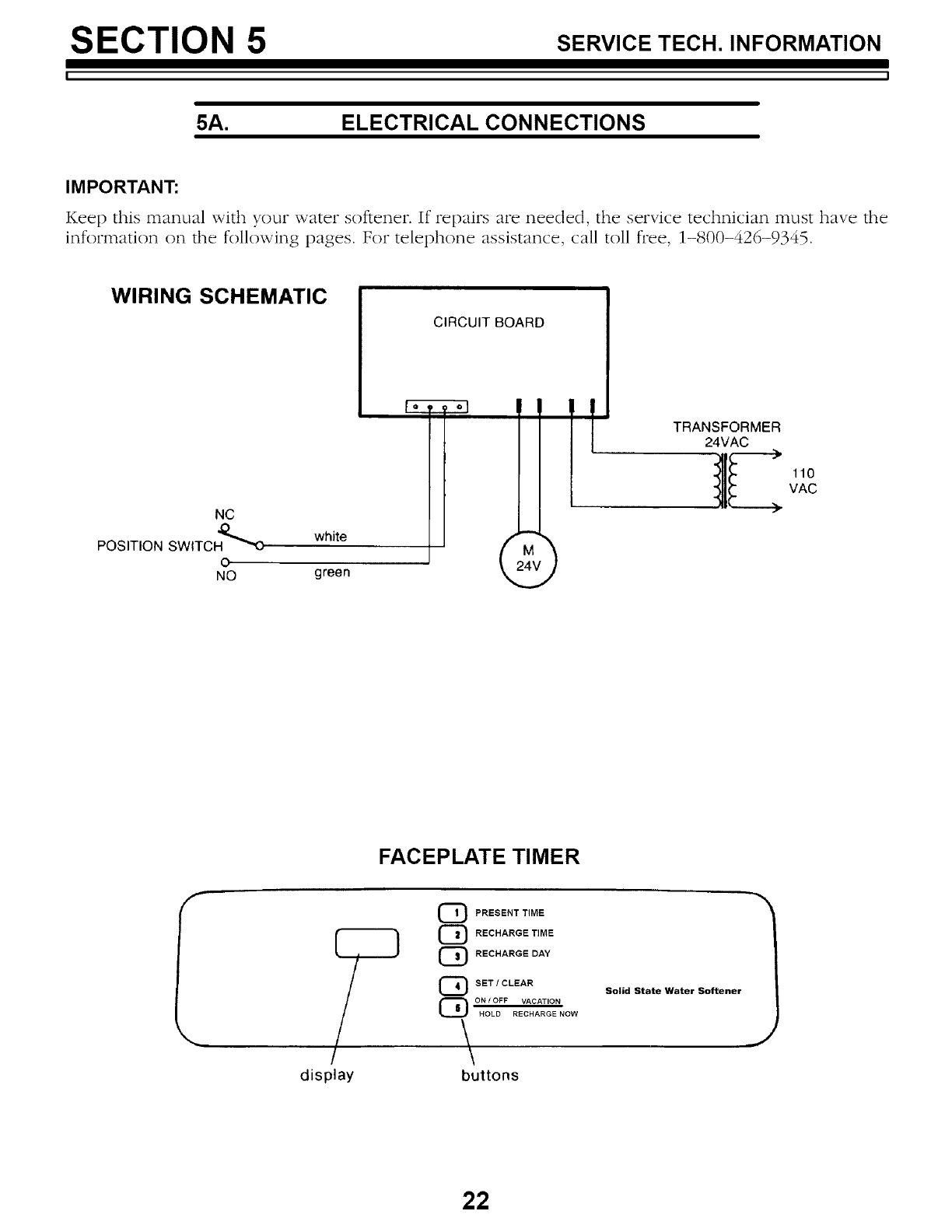
5A. ELECTRICAL CONNECTIONS
I M PO RTANT:
Keep this manual with your water softener. If repairs are needed, the service technician must have the
information on the following pages. For telephone assistance, call toll flee, 1-800-426-9345.
WIRING SCHEMATIC
CIRCUIT BOARD
NC
POSITION SWITCH_O white
0
NO green
TRANSFORMER
24VAC )-
110
VAC
FACEPLATE TIMER
f
display
Q PRESENT TIME
C_ RECHARGE TIME
C_ RECHARGE DAY
C_ SET /CLEAR
{_ ON /OFF VACATION
HOLD RECHARGE NOW
\
buttons
Solid State Water Softener
J
22
SECTION 5 SERVICE TECH. INFORMATION
LJ
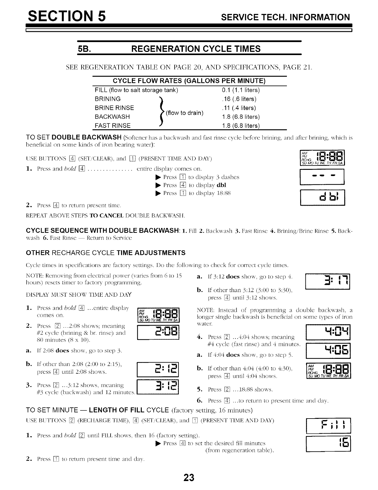
5B. REGENERATION CYCLE TIMES
SEE REGENERATION TABLE ON PAGE 20, AND SPECIFICATIONS, PAGE 21.
CYCLE FLOW RATES (GALLONS PER MINUTE)
FILL (flow to salt storage tank) 0.1 (1.1 liters)
BRINING _ .16 (.6 liters)
BRINE RINSE t .11 (.4 liters)
BACKWASH (flow to drain) 1.8 (6.8 liters)
FAST RINSE 1.8 (6.8 liters)
TO SET DOUBLE BACKWASH (Softener has a backwash and fast rinse cycle heft)re brining, and after brining, which is
beneficial on some kinds of iron bearing \_ater):
(SE B( TI'ONS [] (SET/CLEAR), and [] (PRESENT TIME AND DAY)
1. Press and bold [] ............... entire display comes on.
Press [] to display 3 dashes
Press [] to display dbl
Press [] to display 18:88
2. Press [] to return present tilne.
IAM I .O.•L--I
s__ _ _ _"_ s_I
[ db=J
REPEAT ABOVE STEPS TO CANCEL I)O/;BLE BACKWASI t.
CYCLE SEQUENCE WITH DOUBLE BACKWASH: 1. Fill 2. Backwash 3. Fast Rinse 4. Brining/Brine Rinse 5. Back-
\_ash 6. Fast Rinse Return to Service
OTHER RECHARGE CYCLE TIME ADJUSTMENTS
Cycle times ira specifications are factor.v settings. I)o the following to check f()r correct cycle times.
NOTE: Relnoving froln electrical po\_er (varies fiom 6 to 15
hours) resets tiHler to fat:tory programming.
I)ISPLAY M[ST SIIOW TIME AND DAY
a. 1f3:12 does show, go to step 4. --_1 { 71 I
b. If other than 3:12 (3:00 to 3:30),
press [] until 3:12 shows.
1. Press an(1 bold [] ...entire (lisplav I_,_ IO.It"lIOI
comes on. I_-_a IU.J't,,]KJI
iSUMOrUWeTH FR SA I
2. Press [] ...2:08 SHOWS; ine;-liqiiqg _ OB I]
#2 cycle brinin{_ & t....-"• ( _, hr. rinse) and
80 ininutes (8 x 10).
If 2:08 does show, g(}t(} step 3.
ao
b.
.
If other than 2:08 (2:00 to 2:15),
press [] until 2:08 sho\Ts.
Press [] ...3:12 sho\\s, meaning
#3 cycle (backwash) and 12 minutes.
2" 12
It.=
NOTE: Instead of prograHliP_ing a (louble backwash, a
lonoer_ ,sin{fie,_back\T ash is beneficial (}n some types. (}firon
\\ _tter. 14,o41
a. 1 4OSl
b. If other than 4:04 (4:00 to 4:30) '_ i_!.O1[_1
'I_c_ IO'O!lal
press [] until 4:04 shows. IsoMoruWErHFRSaI
Press [] ...4:04 sh(}ws; meaning
#4 cycle (fast rinse) an(1 4 minutes.
If 4:04 does show, go to step 5.
5. Press [] ...18:88 sho\'_s.
6. Press [] ...to rettun to present time an(] (lay.
TO SET MINUTE -- LENGTH OF FILL CYCLE (factory setting, 16 minutes)
(SE BI TTONS [] (RECItARGE TIME), [] (SET/CLEAR), and [] (PRESENT TIME AND I)A¥)
1. Press an(1 bold [] until FILL shows, then 16 (factory setting).
Press [] to set the desire(1 fill ininutes
(flom regenerati(}n table).
2. Press [] to return present tiH_e an(] (lay.
23
SECTION 5 SERVICE TECH. INFORMATION
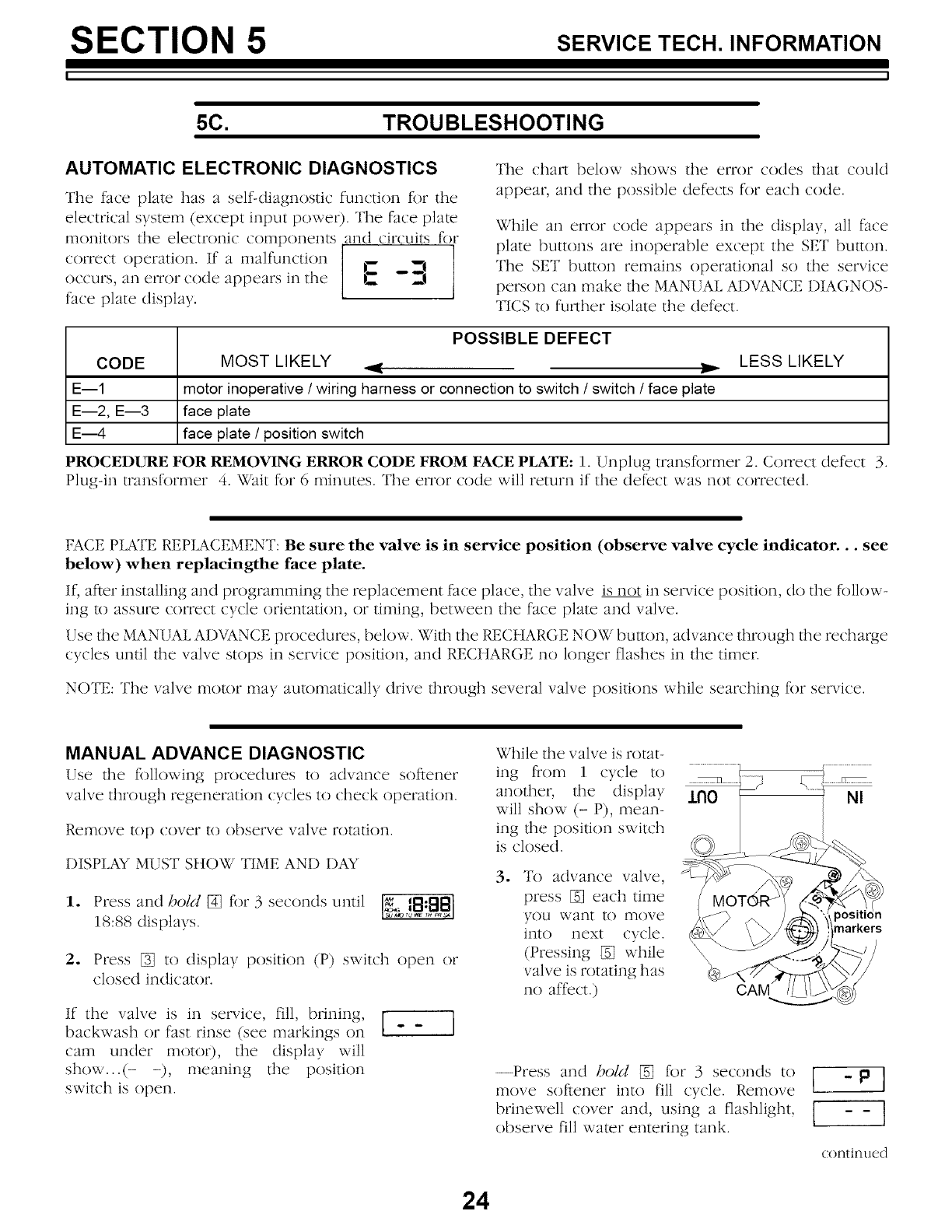
5C. TROUBLESHOOTING
AUTOMATIC ELECTRONIC DIAGNOSTICS
The face plate has a self-diagnostic function for the
electrical s_ stem (except input power). Tile face plate
monitors the electronic components ,and circuits for
correct operation. If a malfunction ] _
occurs, an error code appears in the E --
1
fat'e plate display.
The chart belo_ shows the error codes that could
appear, and the possible defects for each code.
While an error code appears in the display, all face
plate buttons are inoperable except the SET bullon.
The SET button remains operational so the service
person can make lhe MANUAL ADVANCE DIAGNOS-
TICS to further isolate the defect.
CODE
E--1
E--2, E--3
E---4
POSSIBLE DEFECT
MOST LIKELY _..
motor inoperative /wiring harness or connection to switch /switch /face plate
face plate
face plate /position switch
LESS LIKELY
PROCEDURE FOR REMOVING ERROR CODE FROM FACE PLATE: 1. Unplug transformer 2. Correct defect 3.
Plug-in transforn_er 4. Wait for 6 minutes. The errt/r code will return if the defect was not corrected.
FACE PLATE REPLACEMENT: Be sure the valve is in service position (observe valve cycle indicator.., see
below) when replacingthe face plate.
If, after installing and programming the replacement face place, the valve is not in service position, do the follow-
ing lo assure correct cycle (/rientation, (/r timing, between the face plate and valve.
Use fl_e MANUAL ADVANCE procedures, below. Will_ the RECHARGE NOW buuon, advance through fl_e recharge
cycles unlil file valve stops in service position, and RECttARGE no longer flashes in the timer.
NOTE: The valve molor may aulomatically drive flmmgh several valve posilions while searching for service.
MANUAL ADVANCE DIAGNOSTIC
Use lhe following procedures to advance softener
valve through regeneration cycles to check operation.
Remove kip cover lo observe valve rotalion.
DISPIAY MUST SttOW TIME AND DAY
1. Press and boM [] for 3 seconds until _ 18:881
Is_ _ao?_ _ T_S4 I
18:88 displays.
2. Press [] to display positi(/n (P) switch (/pen or
closed indicator.
If the valve is in service, fill, brining,
backwash or fast rinse (see markings on
cam under motor), the display will
show...(- meaning the positi(/n
switch is open.
While fl_e valve is rotat-
ing from 1 cycle to ......................................
another, file display J.llO
will show (- P), mean-
ing the posidon switch
is closed.
3. To advance valve,
press [] each time
you want to move
into next cycle.
(Pressing [] while
valve is rotating has
no affect.) CAM
ion
--Press and hold [] for 3 seconds to I - PI
move softener into fill cycle. Rem(/ve
brinewell c(/ver and, using a flashlight, ['-- - - 1
(/bserve fill water entering tank. lt
continue(1
24
SECTION 5 SERVICE TECH. INFORMATION
5C. TROU BLESHOOTING
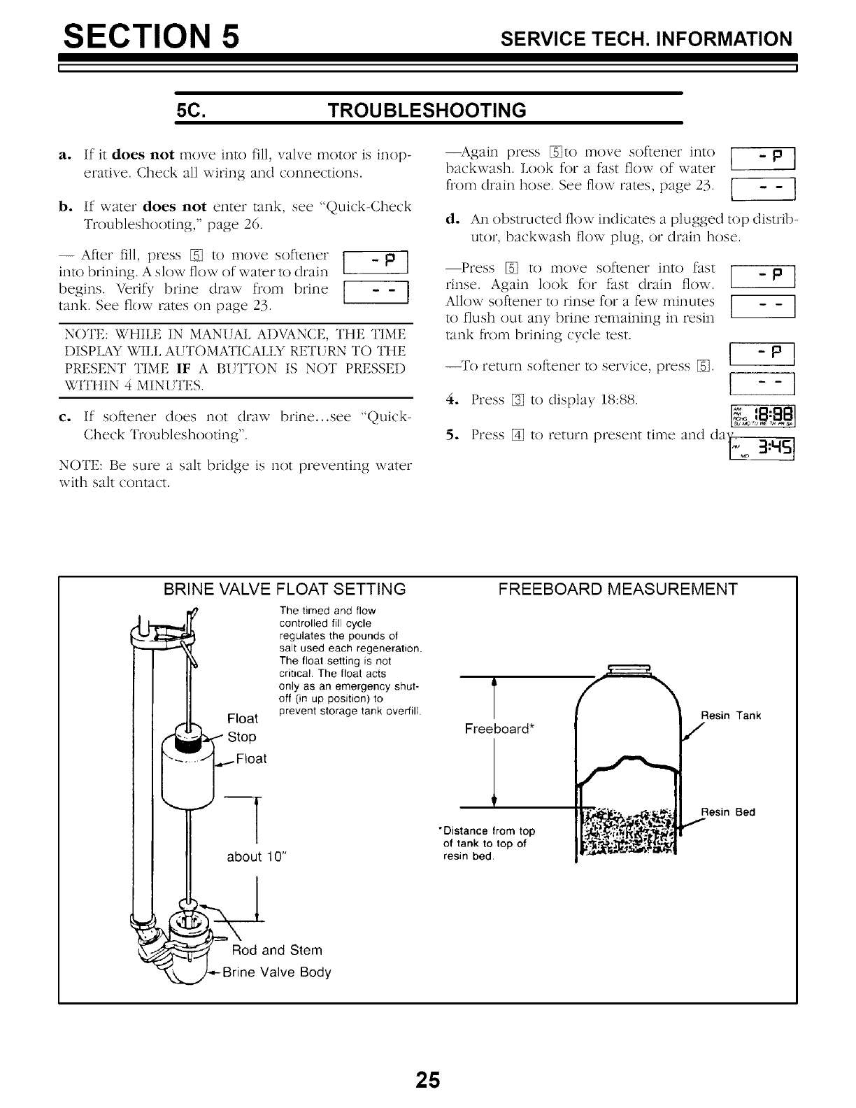
a. If it does not move into fill, valve motor is inop-
erative. Check all _iring and connections.
b. If _ater does not enter tank, see Quirk-Check
Troubleshooting," page 26.
- Ar,et rill,pFess[] tomovesof,eneF[ _p ]
into brining. A slow flow of _ ater to drain
begins. Vetif)brine draw from brine [ -- ]
tank. See flow rates on page 23. l 1
NOTE: WHILE IN MANUAL ADVANCE, THE TIME
DISPLAY WILL AUTOMATICALIX RETURN TO THE
PRESENT TIME IF A BUTTON IS NOT PRESSED
WITttIN 4 MINUTES.
c. If softener does not draw brine...see "Quick-
Check Troublestaooting".
NOTE: Be sure a sltlt bridge is not preventing water
v_ith sltlt contact.
--Againptess _to movesofleneFinto [ - la ]
backwash. Ix)ok for a fast flow of water
ftom,,Fi,i, hoseSee o,,Fi, es,pl,ge 3 1 --1
d. An obstructed flow indicates a plugged top distrib-
utor, backwastn flow plug, or drain hose.
Press [] to move softener into fast
rinse. Again look for fast drain flow. [ - p J
Allow softener to rinse for a few minutes ] - - I
to flush out any brine remaining in resin
tank flom brining cycle test. [ -Pl
[ --I
Press [] to return present time and dai,_ 2_:t.{S]
To return SOftener to service, press [].
4. Press [] to display 18:88.
o
BRINE VALVE
Float
FLOAT SETTING
The timed and flow
controlled fill cycle
regulates the pounds of
salt used each regeneration.
The float setting is not
critical. The floal acts
only as an emergency shut-
off (in up position) to
prevent storage tank overfill.
FREEBOARD MEASUREMENT
T
Freeboard* Resin Tank
-I
about 10"
*Distance from top
of tank to top of
resin bed,
Resin Bed
Rod and Stem
Valve Body
25
SECTION 5 SERVICE TECH. INFORMATION
5C. TROU BLESHOOTING
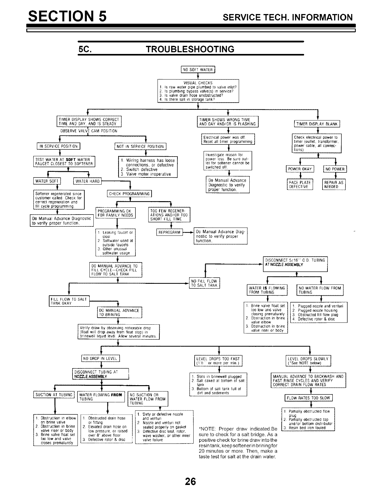
INO SOFT WATER I
F
VISUAL CHECKS
1 is raw water pipe plumbed to valve inlet?
2. Is plumbing bypass valve(s) in service?
3 Is valve drain hose unobstructed?
4 Is there sad in sterage tank';
lTIMER DISPLAY SHOWS CORRECT ]*,M,,.oo,,,,o,,,,,,oY
i
OBSERVE VALVE CAM POSITION
|
I IN SERVICE POSITION I
!
TEST WATER AT SOFT WATER I
FAUCET CLOSEST TO SOFTENER I
tI
L ÷
[WATE,SO.I IWA'ERBABOI
"!
Softener regenerated since
customer called Check for
correct regenerabon and
cyc eprogramming
'l
Do Manual Advance Diagnostic --
to verfy proper uncton,
I
INOT,NSERV,CEPOS,T,ON]
!
1 Wiritlg harness has loose
connections, or defective
2 Switch defective
3 Valve motor inoperative
1
[cHEckPROORAMMINO]
f
ft
PROGRAMMING OK I TOO FEW REGENER-
FOR FAMILY NEEDS I ATIONS AND/OR TOO
SHORt FiLL lIME
f
TIMER SHOWS WRONG TIME I
AND DAY AND/0R IS FlASHiNG I
$
Electrical power was of{ I
Reset al bmer programming I
t
Investigate reason for
power loss Be sure out-
]el for seltener cannot be
switched oN
!
Do Manual Advance I
i
Diagnostic to verify Iproper function,
ITIMERDISPLAYBLANKI
Check electrical power to
bmer (oullet, translormer,
power cable, all connec-
tions) t
REPROGRAM_ Do Manual Advance Diag-
'I nostic to verify proper
| function.
1 Leaking faucet or
stool
2 Softwaler used at
outside faucets
3 Other unusual
sottwater usage
_' DISCONNECT 5/16- B D TUBING
DO MANUAL ADVANCE TO /•AT NOZZLE ASSEMBLY
TILL CYCLE--CHECK FILL t
FLOW TO SALT TANK _'
NoF.LFLOWI I !
"{TO SALT TANKJ
1 WATER IS FLOWING I
FROM TUBING [ TNuOB_WNA;ER FLOW FROM
F'LLFLDWTOSALTI
TANK OKAY 1Brine valve float set li Plugged nozzle and venturi
too low and valve Plugged nozzle housing
closing prematurely Obstructed li]l flow plug
2 Obstruction in brine Defective rotor & disc
valve elbow
3 Obstruction in brine
valve riser or body
f
DO MANUAL ADVANCE I
TO BRINING 1
{
Verify draw by observing noticeable drop I
(float will drop away from float stop) in I
br newe liquid level Allow several minutes
t
t
INODROR,NLEVELI
!o°O TOO *l.v.,o.o ss,ow I
(l'h or more per rain ) ('See NOTE below)
! ÷
DISCONNECT TUB NG AT
INOZZLEASSEMBLV iI1 Slots in brinewell plugged ]IMANUAL ADVANCE TO BACKWASH AND
I 2 Salt caked at bottom of sail ]FAST RINSE CYCLES AND VERIFY
1
tank
_' 3 Bottom of salt tank furl of CORRECT DRAIN FLOW RATES
SUCTION AT TUBING WATER FLOWING FIqOM NO SUCTION OR II d rt and sod meats [ '_ )
lI' I TUBING II WATER FLOW FROM IIFLOW RATES TOO SLOW I
l ' L' , TUBING J
t 0bstructiont_ ,]inbrine , ,2. _Elevated on. |_- _t_ve nozzle -il Parliatly Obstructed flow ]1
[- 0bstructon no bow I1 Obstructed dram hose _ and ventub P%U_laily obstrucIed top I
{on brine vane I / or fitting |[2 Nozzle and venturi not and/or bottom distributor
12 drain hose seated propeDy on gasket Resin bed iron louled ]
/ valve riser or body /low pressure, or raised] ]3 Detective disc sea] rotor, *NOTE: Proper draw indicated.Be
13 Brine valve float set lover 8' above floor l wave washer, or o her inner sure to check for a salt bridge. As a
| toe low and valve ]3 Detective rotor & disc /va vea ere positive check for brine draw into the
L closes prematurely J _ _ L resintank, keepsoftenerinbriningfor
20 minutes or more. Then, make a
taste test for salt at the drain water.
26
SECTION 5 SERVICE TECH. INFORMATION
5D. ROTARY VALVE SERVICE
Before working on tile valve, turn off the water
supply and disconnect from electrical power. TO
RELIEVE PRESSURE:
-- 3 VALVE BYPASS: Close file inlet valve and open a
soft walcr faucet. Then close tile outlet valve and open
the bypass valve.
-- SEARS SPECIAL BYPASS: Slide tile bypass valve
slcm to bypass position. Leo,veto lhe 3 hex head screws
(see A in drawing) toward the back side of fl_e valve to
allow pressure walcr 1o bleed out (catch water with a
rag).
DISASSEMBLY
To remove a pat_ or group of pat_s, refer to ll_e valve
drawing. Acommon screwdriver or nut driver, Phillips
screwdriver and pliers are the only lot)is needed to
complemly disassembe.
SERVICING THE VALVE
Inspect all o-rings, seals and gaskels for wear or
defects.
Inspect the bottom surf_ce of tile rotor and disc for
scratches, chips or wear.
NOTE: If replacement is needed, be sure to use tile
current replacement pat_.
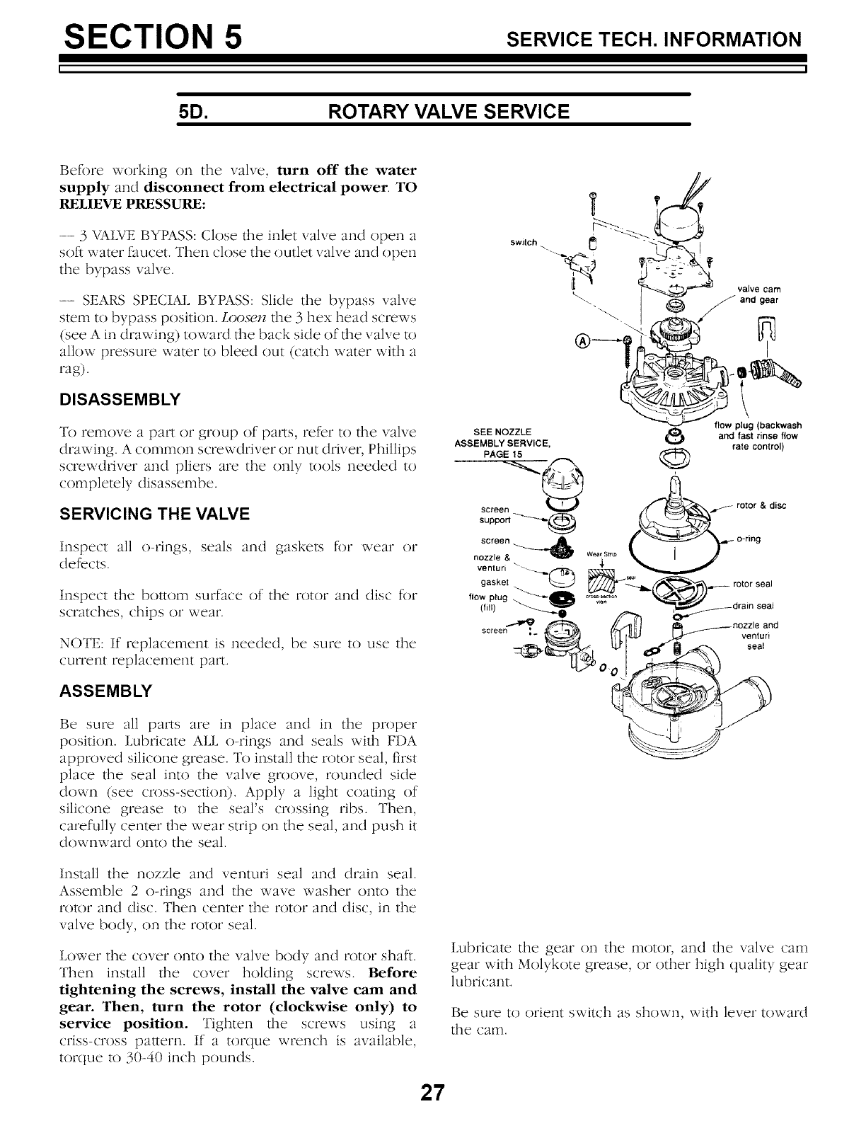
ASSEMBLY
Be sure all parts are in place and in the proper
position. Lubricate ALL o-rings and seals wilh FDA
approved silicone grease. T() install tile rotor seal, first
place file seal into the valve groove, rounded side
down (see cross-seclion). Apply a light coaling of
silicone grease 1o the seal's crossing ribs. Then,
carefully center lhe wear strip on the seal, and push it
downward onto the seal.
Install the nozzle and venturi seal and drain seal.
Assemble 2 o-rings and the wave washer onto the
tolof and disc. Then center the totof and disc, in tile
valve body, on the totof seal.
Lower the cover onto tile valve body and rotor shaft.
Then install file cover holding screws. Before
tightening the screws, install the valve cam and
gear. Then, turn the rotor (clockwise only) to
service position. Tighten file screws using a
criss-cross pallern. If a tor(tue wrench is available,
tor(lue 1o 30-40 inch pounds.
switch
SEE NOZZLE
ASSEMBLY SERVICE,
V..... /1__-_ valve cam
flow plug (backwash
and fast rinse flow
rate control)
Lubricalc tile gear on the motor, and fl_e valve cam
gear with Molykote grease, or other high quality gear
lubricant.
Be sure to orient switch as shown, with lever toward
the cam.
27
SECTION 5 SERVICE TECH. INFORMATION
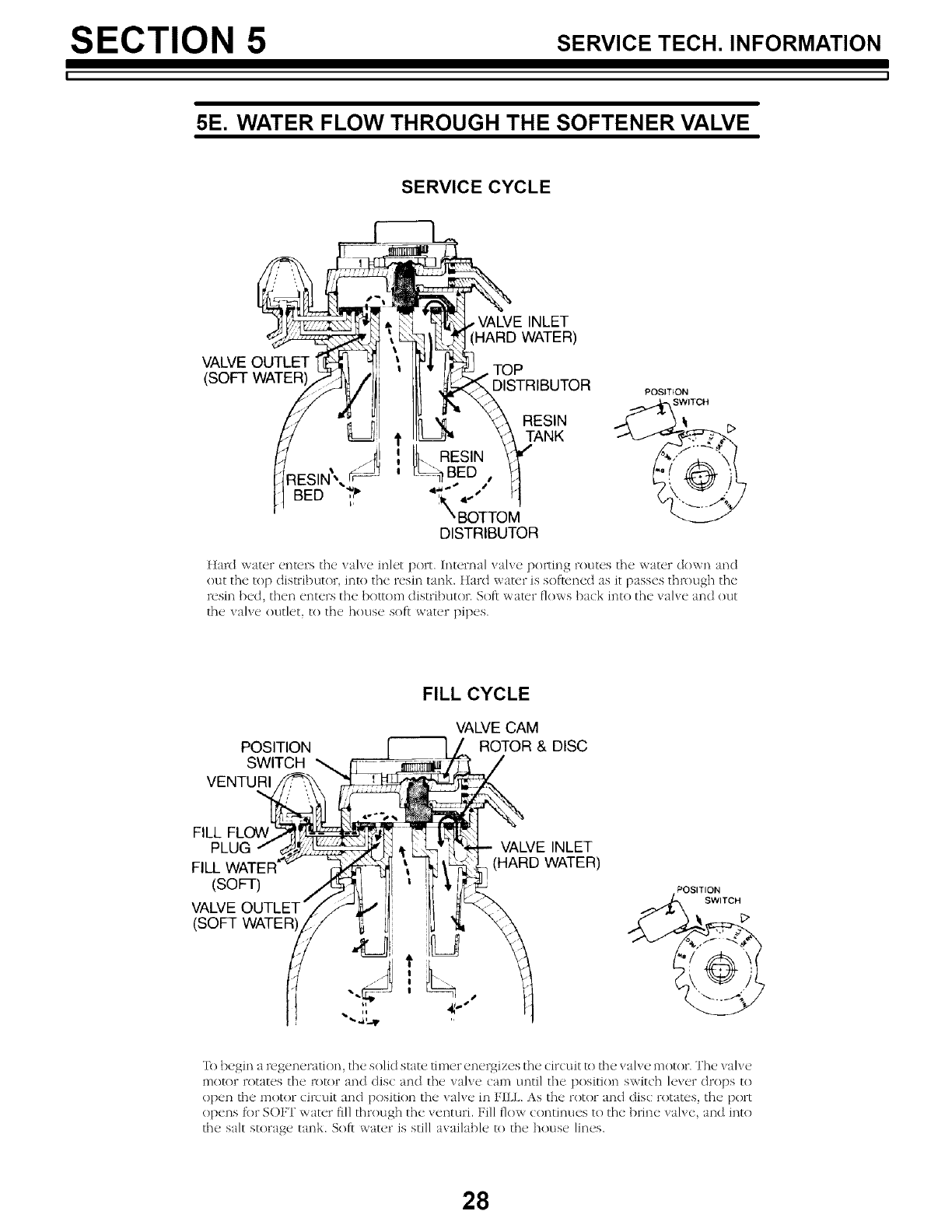
5E. WATER FLOW THROUGH THE SOFTENER VALVE
SERVICE CYCLE
INLET
WATER)
VALVE OUTLET TOP
(SOFT WATER' DISTRIBUTOR POSITION
SWITCH
]tard water enters the valve inlet port. internal wdve po_Ting routes the water down and
out the top distributor, into the resin tank. Hard water is softened as it passes through the
rusm bed, then enters the bottom distributor. Soft water flows ba(k into the valve and out
the valve outlet, to the house soft water pipes.
POSITION
SWITCH
VENTURI
FILL CYCLE
VALVE CAM
ROTOR & DISC
FILL FLOW
PLUG VALVE INLET
FILL WATER (HARD WATER)
(SOFT) POS,T,ON
VALVE OUTLET" SW,TCH
(SOFT WATER _"
'Ik)begin a regeneration, the solid state timer energizes the circuit to the valve motor. The valve
motor rotates the rotor and <tis( and the valve (am until the position switch lever drops to
<)pen the motor (ir(uit and position the valve in FILL. As the rotor and (]is(: rotates, the port
<)pens ti)r S()FI' water fill through the venturi. Fill flow continues to the brine wdve, and into
the salt storage tank. Soft water is still available to the house lines.
28
SECTION 5 SERVICE TECH. INFORMATION
5E. WATER FLOW THROUGH THE SOFTENER VALVE
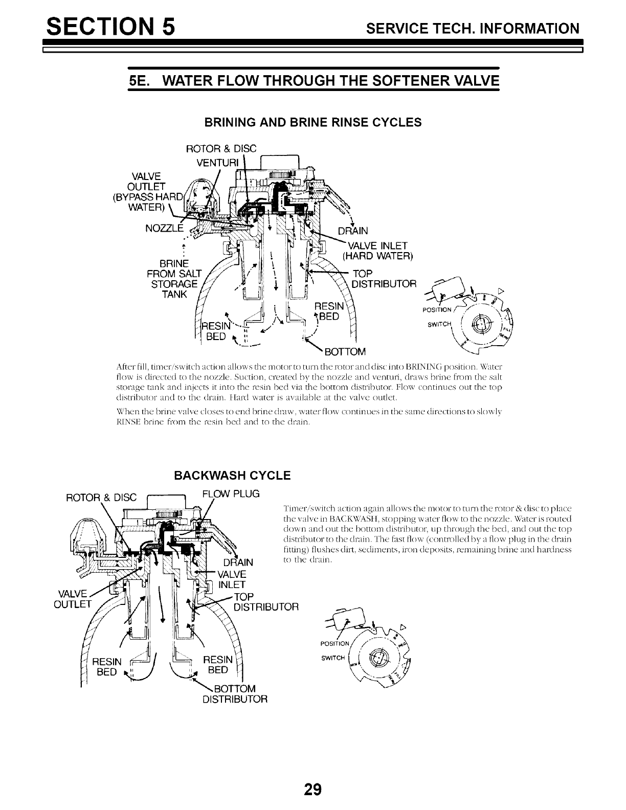
BRINING AND BRINE RINSE CYCLES
ROTOR & DISC
VENTURI
VALVE
OUTLET
(BYPASS
WATER)
NOZZLE DRAIN
€
BRINE
FROM SALT
STORAGE
TANK
INLET
(HARD WATER)
TOP
DISTRIBUTOR
After fill, timer/switch action allows tile motor to turn the rotor and (]is(: into BRINING position. Water
flow is directed to tile nozzle. Suction, created b} tile nozzle and ventun, draws brine fi-om tile salt
storage tank and injects it into tile resin bed via tile bottom distributor. Flow continues out tile top
distributor and to the drain, fIard water is awdlable at the valve outlet.
\X'hen tile brine xahe closes to end brine draw, _ ater flow continues in tile same directions to slox_ Ix
RINSE brine from the resin bed and to the drain.
ROTOR & DISC
OUTLET
RES,.
BED _/
BACKWASH CYCLE
FLOW PLUG
_VE
INLET
Timeris wit(h action again allows tile motor to turn tile rotor & disc to pla(e
the valve in BACKWASft, stopping water flow to the nozzle. \\,ater is routed
down and out the bottom dislributor, up through the bed, and out the top
distributor to tile drain. The [hst flow (conm)lled by a flow plug in tile dram
fitting) fltlshes dirt, sediments, iron deposits, remaining brine and haR]ness
to tile drain.
DISTRIBUTOR
_ RESIN
BED
"_. BOTTOM
DISTRIBUTOR
29
SECTION 5 SERVICE TECH. INFORMATION
5E. WATER FLOW THROUGH THE SOFTENER VALVE
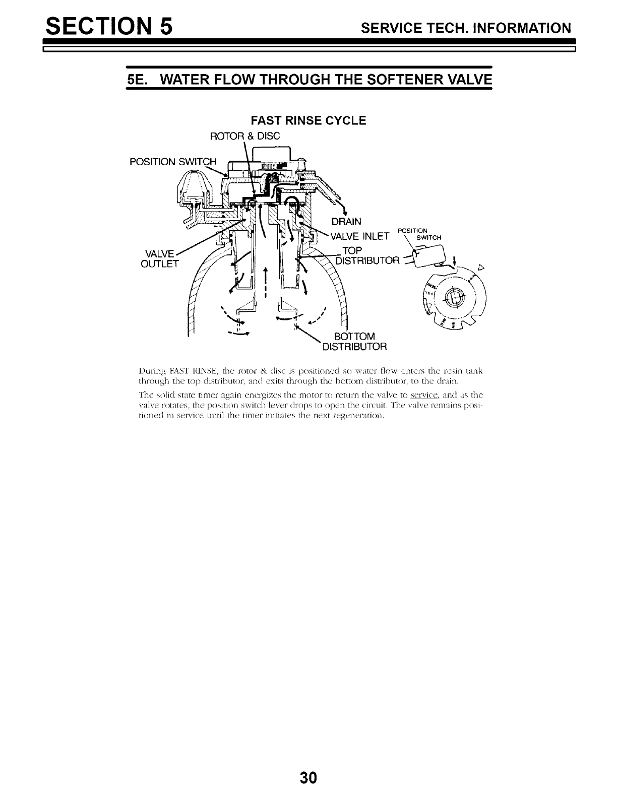
FAST RINSE CYCLE
ROTOR & DISC
POSITION SWITCH
OUTLET
DRAIN
POSITION
INLET
TOP
, 4,''/ DISTRIBUTOR _@
'% BOTTOM
DISTRIBUTOR
During D\ST RINSE, the rotor & disc is positioned so water flow ente_ts the resin tank
through the top distributor, and exits through the bottom distributor, to the drain.
The solid state timer again energizes the motor to return the valve to service, and as the
valve rotates, the position swit(h lever drops to ()pen the circuit. The wdve remains posi-
tioned in servi(e until the timer initiates the next regeneration.
30

SECTION 5 SERVICE TECH. INFORMATION
L .I
NOTES
31
SECTION 6 REPAIRPARTS
I ]
27 1_
2
VALVE ASSEMBLY
3 (seepage34)
I
25
24
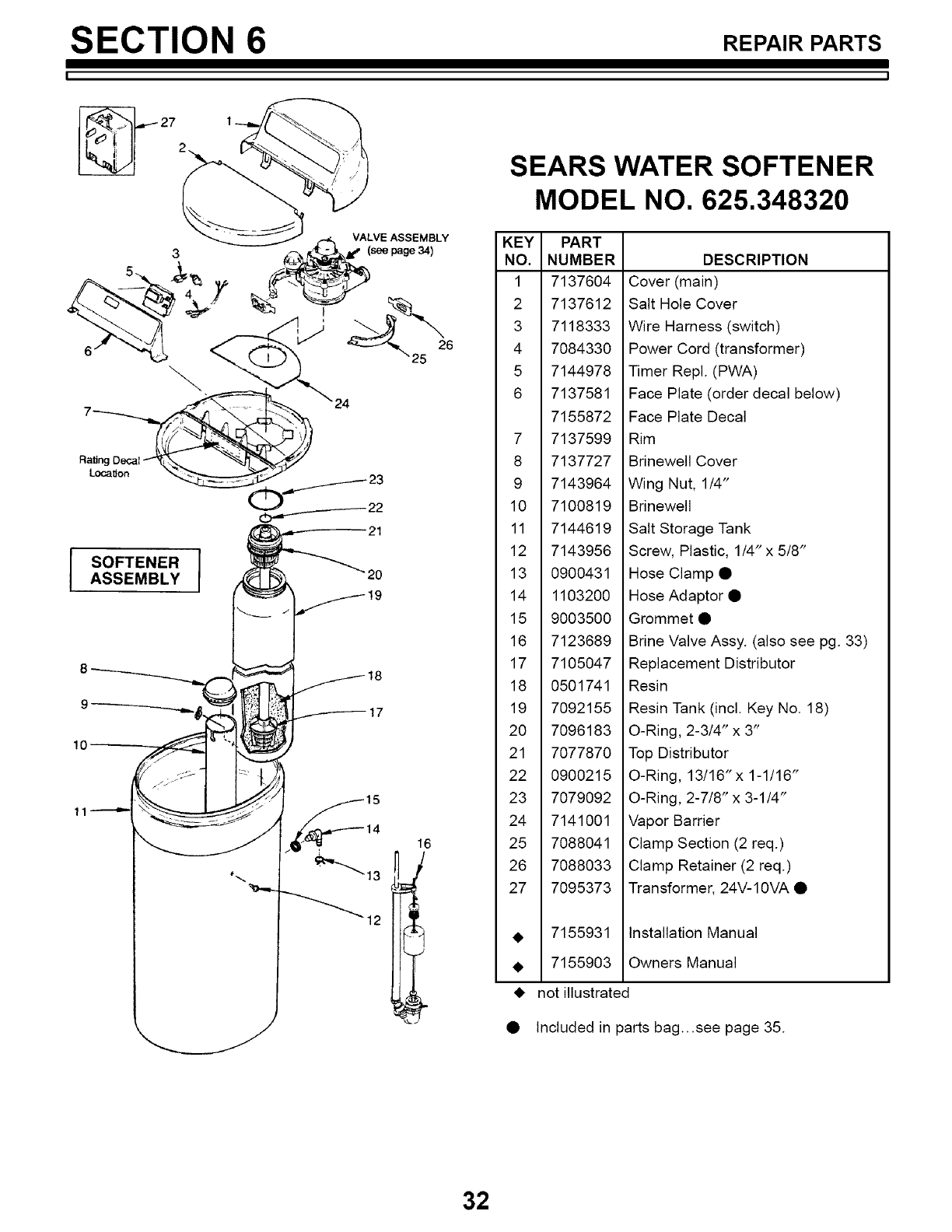
SEARS WATER SOFTENER
MODEL NO. 625.348320
KEY PART
NO. NUMBER
1 7137604
2 7137612
3 7118333
4 7084330
5 7144978
6 7137581
7155872
7 7137599
8 7137727
9 7143964
10 7100819
11 7144619
12 7143956
13 0900431
14 1103200
15 9003500
16 7123689
17 7105047
18 0501741
19 7092155
20 7096183
21 7077870
22 0900215
23 7079092
24 7141001
25 7088041
26 7088033
27 7095373
Ra_nc
LocaSon
21
SOFTENER
ASSEMBLY "2o
17
12
16
• 7155931
• 7155903
DESCRIPTION
Cover (main)
Salt Hole Cover
Wire Harness (switch)
Power Cord (transformer)
Timer Repl. (PWA)
Face Plate (order decal below)
Face Plate Decal
Rim
Brinewell Cover
Wing Nut, 1/4"
Brinewell
Salt Storage Tank
Screw, Plastic, 1/4" x 5/8"
Hose Clamp •
Hose Adaptor •
Grommet •
Brine Valve Assy. (also see pg. 33)
Replacement Distributor
Resin
Resin Tank (incl. Key No. 18)
O-Ring, 2-3/4" x 3"
Top Distributor
O-Ring, 13/16" x 1-1/16"
O-Ring, 2-7/8" x 3-1/4"
Vapor Barrier
Clamp Section (2 req.)
Clamp Retainer (2 req.)
Transformer, 24V-10VA •
Installation Manual
Owners Manual
not illustrated
Included in parts bag...see page 35.
32
SECTION 6 REPAIRPARTS
I I
47--_
BRINE VALVE
ASSEMBLY
46
45
44
! ,
43
3O
_/---- 31
32
_1---- 34
.-t 35
36
L
42 _ __ _ 39
41 -_ '_-_J_'_ _ 40
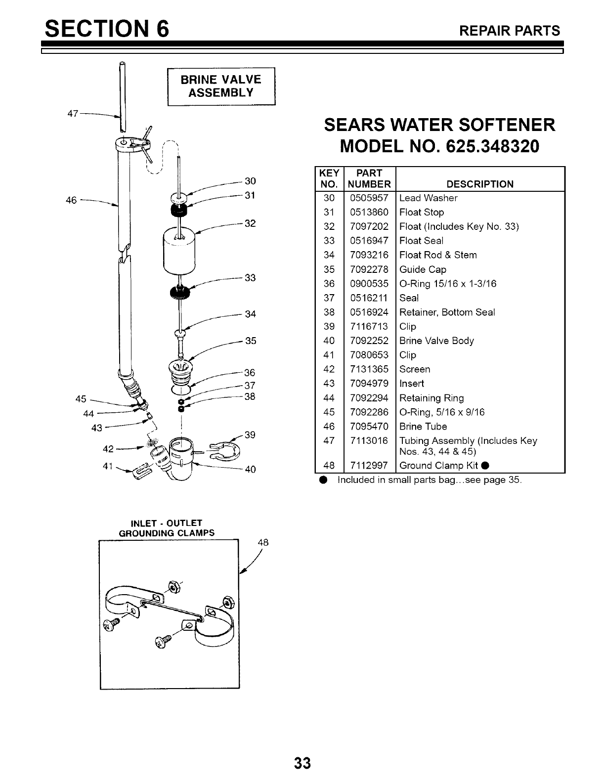
SEARS WATER SOFTENER
MODEL NO. 625.348320
KEY PART
NO. NUMBER
30 0505957
31 0513860
32 7097202
33 0516947
34 7093216
35 7092278
36 0900535
37 0516211
38 0516924
39 7116713
40 7092252
41 7080653
42 7131365
43 7094979
44 7092294
45 7092286
46 7095470
47 7113016
48 7112997
DESCRIPTION
Lead Washer
Float Stop
Float (Includes Key No. 33)
Float Seal
Float Rod & Stem
Guide Cap
O-Ring 15/16 x 1-3/16
Seal
Retainer, Bottom Seal
Clip
Brine Valve Body
Clip
Screen
Insert
Retaining Ring
O-Ring, 5/16 x 9/16
Brine Tube
Tubing Assembly (Includes Key
Nos. 43, 44 & 45)
Ground Clamp Kit •
Included in small parts bag...see page 35.
INLET-OUTLET
GROUNDING CLAMPS 48
/
33
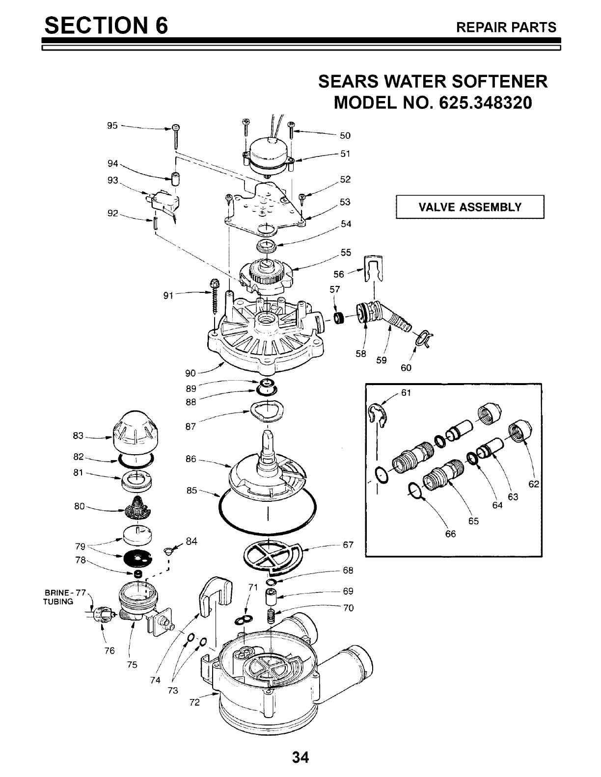
SECTION 6 REPAIRPARTS
I ]
SEARS WATER SOFTENER
MODEL NO. 625.348320
IVALVE ASSEMBLY I
BRINE- 77.,,
TUBING _
76
75 /
74
73
72
60
61
66
64
65
\
63
34
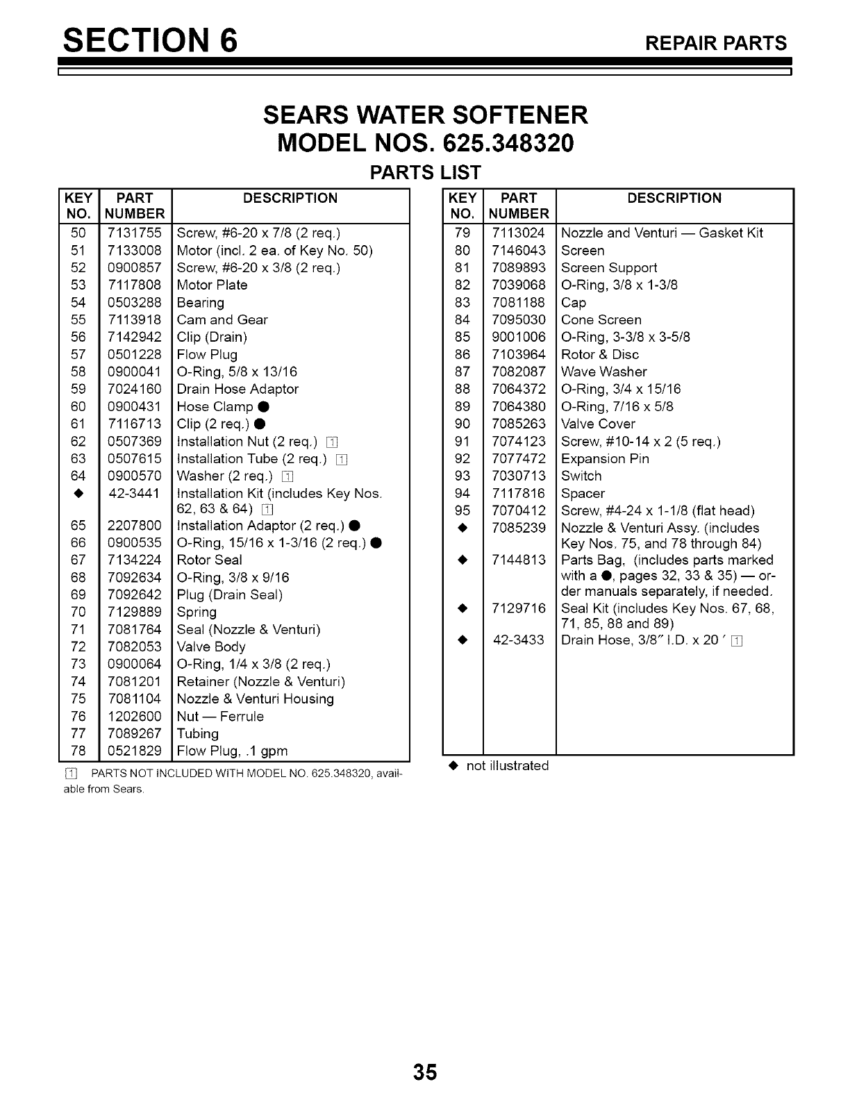
SECTION 6 REPAIRPARTS
I I
SEARS WATER SOFTENER
MODEL NOS. 625.348320
PARTS LIST
KEY PART
NO. NUMBER
50 7131755
51 7133008
52 0900857
53 7117808
54 0503288
55 7113918
56 7142942
57 0501228
58 0900041
59 7024160
60 0900431
61 7116713
62 0507369
63 0507615
64 0900570
• 42-3441
65 2207800
66 0900535
67 7134224
68 7092634
69 7092642
70 7129889
71 7081764
72 7082053
73 0900064
74 7081201
75 7081104
76 1202600
77 7089267
78 0521829
DESCRIPTION
Screw, #6-20 x 7/8 (2 req.)
Motor (incl. 2 ea. of Key No. 50)
Screw, #6-20 x 3/8 (2 req.)
Motor Plate
Bearing
Cam and Gear
Clip (Drain)
Flow Plug
O-Ring, 5/8 x 13/16
Drain Hose Adaptor
Hose Clamp •
Clip (2 req.) •
Installation Nut (2 req.)
Installation Tube (2 req.) [_
Washer (2 req.) [_
Installation Kit (includes Key Nos.
62, 63 & 64)
Installation Adaptor (2 req.) •
O-Ring, 15/16 x 1-3/16 (2 req.) •
Rotor Seal
O-Ring, 3/8 x 9/16
Plug (Drain Seal)
Spring
Seal (Nozzle & Venturi)
Valve Body
O-Ring, 1/4 x 3/8 (2 req.)
Retainer (Nozzle & Venturi)
Nozzle & Venturi Housing
Nut -- Ferrule
Tubing
Flow Plug, .1 gpm
PARTS NOT INCLUDED WITH MODEL NO. 625.348320, avaiI-
able from Sears.
KEY PART
NO. NUMBER
79 7113024
80 7146043
81 7089893
82 7039068
83 7081188
84 7095030
85 9001006
86 7103964
87 7082087
88 7064372
89 7064380
90 7085263
91 7074123
92 7077472
93 7030713
94 7117816
95 7070412
• 7085239
• 7144813
• 7129716
• 42-3433
DESCRIPTION
Nozzle and Venturi -- Gasket Kit
Screen
Screen Support
O-Ring, 3/8 x 1-3/8
Cap
Cone Screen
O-Ring, 3-3/8 x 3-5/8
Rotor & Disc
Wave Washer
O-Ring, 3/4 x 15/16
O-Ring, 7/16 x 5/8
Valve Cover
Screw, #10-14 x 2 (5 req.)
Expansion Pin
Switch
Spacer
Screw, #4-24 x 1-1/8 (flat head)
Nozzle & Venturi Assy. (includes
Key Nos. 75, and 78 through 84)
Parts Bag, (includes parts marked
with a O, pages 32, 33 & 35) -- or-
der manuals separately, if needed.
Seal Kit (includes Key Nos. 67, 68,
71, 85, 88 and 89)
Drain Hose, 3/8" I.D. x 20 ' [_
• not illustrated
35
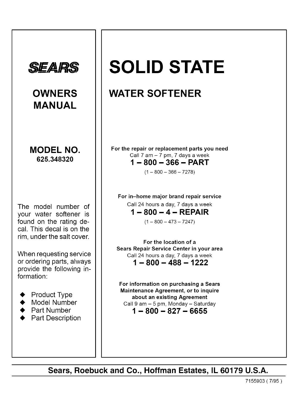
_ARS
OWNERS
MANUAL
MODEL NO.
625.348320
The model number of
your water softener is
found on the rating de-
cal. This decal is on the
rim, under the salt cover.
When requesting service
or ordering parts, always
provide the following in-
formation:
_I, Product Type
_I, Model Number
_I, Part Number
_I, Part Description
SOLID STATE
WATER SOFTENER
For the repair or replacement parts you need
Call 7 am - 7 pm, 7 days a week
1 - 800 - 366 - PART
(1 - 800 - 366 - 7278)
For in-home major brand repair service
Call 24 hours a day, 7 days a week
1 - 800 - 4 - REPAIR
(1 - 800 - 473 - 7247)
For the location of a
Sears Repair Service Center in your area
Call 24 hours a day, 7 days a week
1 - 800 - 488 - 1222
For information on purchasing a Sears
Maintenance Agreement, or to inquire
about an existing Agreement
Call 9 am - 5 pm, Monday - Saturday
1 - 800 - 827 - 6655
Sears, Roebuck and Co., Hoffman Estates, IL 60179 U.S.A.
7155903 ( 7/95 )
