Kenmore 625348732 User Manual WATER SOFTENER Manuals And Guides L9090082
KENMORE Water softener Manual L9090082 KENMORE Water softener Owner's Manual, KENMORE Water softener installation guides
User Manual: Kenmore 625348732 625348732 KENMORE WATER SOFTENER - Manuals and Guides View the owners manual for your KENMORE WATER SOFTENER #625348732. Home:Plumbing Parts:Kenmore Parts:Kenmore WATER SOFTENER Manual
Open the PDF directly: View PDF ![]() .
.
Page Count: 36
I4 _A/RS
OWNERS
MANUAL
MODEL NO.
625.348732
-j
CAUTION
Read All Safety
Guides Before
You Start to
Install Your
Softener
AVOID UNNEEDED
SERVICE CALLS...
Read the HELPFUL HINTS
CHECKLIST on page 24.
The programming guides on
the underside of the Salt
Storage Tank Cover are also
helpful.
ISAVE THIS MANUAL
High Capac,ty zo
-- HOW TO INSTALL
HOW IT WORKS
-- CARE OF
-- SPECIFICATIONS --
REPAIR PARTS
Sears, Roebuck and Co., Chicago, III. 60684 U.S.A.
PRINTED IN U.S.A.
I WARRANTY
SEARS RESIDENTIAL WATER SOFTENER
FULL ONE YEAR WARRANTY ON WATER SOFTENER
For one year from the date of purchase, when this water softener is installed and maintained
in accordance with our instructions, Sears will repair, free of charge, defects in material
or workmanship in this water softener.
JFULL TEN YEAR WARRANTY AGAINST LEAKS
For ten years from the date of purchase, Sears will furnish and install a new current model
water softener tank or salt storage drum, free of charge, if either the tank or drum develop
a leak.
TO OBTAIN WARRANTY SERVICE, SIMPLY CONTACT THE NEAREST SEARS SERVICE
CENTER THROUGHOUT THE UNITED STATES, This warranty applies only while this pro-
duct is in use in the United States.
This warranty gives you specific legal rights, and you may have other rights which vary from
state to state.
Sears, Roebuck and Co., Dept. 731-CR-W, Sears Tower, Chicago, IL 60684
If you want your water softener professionally installed, talk to your Sears Salesman. He will arrange for
a prompt, quality installation by Sears Authorized Installers.
SEARS INSTALLATION POLICY
All installation labor arranged by Sears shall be per-
formed in a neat, workmanlike manner in accordance
with generally accepted trade practices. Further, all
installations shall comply with all local laws, codes,
regulations and ordinances. Customer shall also be
protected, during installation, by insurance relating
to Property Damage, Workman's Compensation and
Public Liability.
SEARS INSTALLATION WARRANTY
In addition to any warranty extended to you on the
Sears merchandise involved, which warranty
becomes effective the date the merchandise is in-
stalled, should the workmanship of any Sears
arranged installation prove faulty within one year,
Sears will, upon notice from you, cause such faults
to be corrected at no additional cost to you.
2
ITABLE OF CONTENTS
ii r
SECTION 1
PAGE
NO.
Unpacking The Softener ....................................... 4
Safety Guides ............................................... 4
Before You Start To Install Your Softener ......................... 5-9
Water System Tests ......................................... 5
Where To Install The Softener ................................. 6
Plan How You Will Install The Softener ......................... 7-8
Tools, Pipe, Fittings and Other Materials Needed ................. 7
SECTION 3 Step By Step Guides To Install Your Softener ..................... 9-14
Install Sears Plastic Bypass Valve ............................. 9
Connect In and Out Pipes To Softener .......................... 10
Fasten Drain Hoses To Softener ............................... 11-12
Check Your Plumbing Work For Leaks .......................... 12
Connect Softener To Electrical Power .......................... 13
Check List of Step By Step Installing Guides .................... 14
Softener Start-Up ............................................ 16-17
Setting The Timer ................................................ 16
Filling The Storage Tank With Salt ................................. 17
SECTION 5 How Your Water Softener Works ..................................... 18-21
RECHARGE NOW and VACATION Face Plate Controls .............. 18
Service and Regeneration, or Recharge ............................ 19-20
Automatic Bypass ................................................ 21
Care of Your Softener ......................................... 21-24
Checking The Salt Storage Level .............................. 21
Breaking a Salt Bridge ....................................... 21
Cleaning The Outer Covers ................................... 22
Cleaning The Nozzle and Venturi .............................. 22
Cleaning Iron From The Resin Bed ............................ 23
Keep Softener From Freezing ................................. 23
Check List Before You Call For Service ......................... 24
SECTION 7 Other Things To Know ......................................... 25-30
How To "Fine-Tune" Your Softener ............................ 25-27
Dimensions and Specifications ................................ 28
Sweat Soldering Tips ........................................ 29
Wiring Connection Diagram ................................... 30
Repair Parts ................................................. 32-35
How To Order Repair Parts .............................. Back Cover
3
SECTION 1 UNPACKING, SAFETY GUIDES I
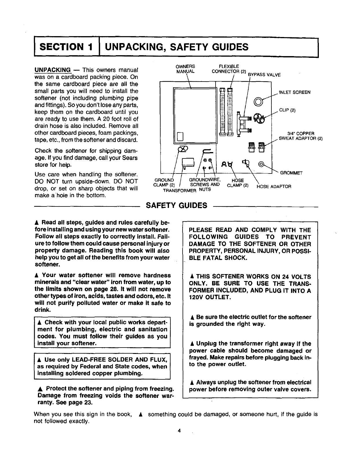
UNPACKING -- This owners manual
was on a cardboard packing piece. On
the same cardboard piece are all the
small parts you will need to install the
softener (not including plumbing pipe
and fittings). So you don't lose any parts,
keep them on the cardboard until you
are ready to use them. A 20 foot roll of
drain hose is also included. Remove all
other cardboard pieces, foam packings,
tape, etc., from the softener and discard.
Check the softener for shipping dam-
age. If you find damage, call your Sears
store for help.
Use care when handling the softener,
DO NOT turn upside-down. DO NOT
drop, or set on sharp objects that will
make ahole in the bottom.
OWNERS
MANUAL
\
GROUND GROUNDWIRE,
CLAMP(2) SCREWS AND
TRANSFORMER NUTS
GROMMET
HOSE
CLAMP(2) HOSE ADAPTOR
SAFETY GUIDES
•Read all steps, guides and rules carefully be-
fore installing and using your new water softener.
Follow all steps exactly to correctly install. Fail-
ure to follow them could cause personal injury or
property damage. Reading this book will also
help you to get all of the benefits from your water
softener.
•Your water softener will remove hardness
minerals and "clear water" iron from water, up to
the limits shown on page 28. It will not remove
other types of Iron, acids, tastes and odors, etc. It
will not purify polluted water or make it safe to
drink.
•Check with your local public works depart-
ment for plumbing, electric and sanitation
codes. You must follow their guides as you
install your softener.
• Use only LEAD-FREE SOLDER AND FLUX, J
as required by Federal and State codes, when
nsta ng so dered copper p umbing.
•Protect the softener and piping from freezing.
Damage from freezing voids the softener war-
ranty. See page 23.
PLEASE READ AND COMPLY WITH THE
FOLLOWING GUIDES TO PREVENT
DAMAGE TO THE SOFTENER OR OTHER
PROPERTY, PERSONALINJURY, ORPOSSI-
BLE FATAL SHOCK.
& THIS SOFTENER WORKS ON 24 VOLTS
ONLY. BE SURE TO USE THE TRANS-
FORMERINCLUDED, AND PLUG ITINTO A
120V OUTLET.
•Be sure the electric outlet for the softener
is grounded the right way.
•Unplug the transformer right away if the
power cable should become damaged or
frayed. Make repairs before plugging back in-
to the power outlet.
•Always unplug the softener from electrical
power before removing outer valve covers.
When you see this sign in the book, • something could be damaged, or someone hurt, if the guide is
not followed exactly.
4
ISECTION 2 IBEFORE YOU START TO INSTALL ]
HELPFUL INFORMATION
If you know little about plumbing skills, we sug-
gest you get a book on the subject. There are
many good books for do-it-yourselfers on the
basics of plumbing. You can get a low cost book
from Sears Plumbing and Heating departments
that will help you. Some basic sweat soldering tips
are on page 29 of this manual.
WATER SYSTEM TESTS
HAS YOUR WATER SUPPLY HAD A CHEMICAL
ANALYSIS? Sears has many kinds of water
treating units (see page 6) to correct different
water problems. To know the kind and size of unit
you need, you must first know what elements are
in your house water supply. Achemical analysis
shows the type and amounts of elements inwater.
If your water needs analysis, call or write your
nearest Sears store for help.
CHECK YOUR WATER PRESSURE -- For your
softener to work right, a water pressure of no lower
than 20 pounds per square inch (psi) is needed
in the house water pipes. The highest pressure
,& allowed in the water pipes is 120 psi. If pressure
is over 120 psi, buy and install a pressure reduc-
ing valve in the water inlet pipe to the softener.
NOTE: If water pressure during the day is 100 psi
or more, pressure during the night may go over
120 psi.
If you have a well water system, look at the
pressure gauge to find the water pressure. Call
your local water department if you have city water.
They will tell you what the water pressure is where
you live.
1.
CHECK YOUR WATER FLOW RATE -- A water
flow of at least 3 gallons per minute is needed.
A lower flow will keep your softener from working
as well as it should. To make an easy check of
your flow rate, do the following. You will need a
1 gallon container (can; jar, pail, etc.).
Fully open 2 cold water faucets close to the point
water enters the house.
.
.
With both faucets open, fill the gallon container
at ! faucet while looking at a watch or clock to
see how many seconds it takes.
Empty the container and go to the second faucet
(be sure BOTH faucets are still on). Fill the gallon
container at the second faucet and see how many
seconds it takes.
4.
5.
Turn off both faucets. Now add the number of
seconds it took to fill the container at both faucets.
Atotal of 80 seconds, or less, means the system
flow rate is good.
FACTS AND FIGURES TO KEEP
Fill in the blanks below and keep this book in a safe place so you always have these facts.
Water Softener Model No. t"
Serial Number
Date Installed
Water Hardness. Grains Per Gallon
Iron Content Parts Per Million
*pH Taste And/Or Odor
Water Pressure Pounds/Square Inch
Water Flow Rate_ Gallons Per Minute
SODIUM INFORMATION: Water softeners using to consume 335 milligrams of sodium. That is
sodium chloride for regeneration add sodium to the equivalent to eating 21/2 slices of white bread.
water. Persons who are on sodium restricted diets
should consider the added sodium as part of their Persons who are concerned about their drinking
overall sodium intake, water should consider a Sears Drinking Water
For example, if your water supply is 15 grains hard, System that will remove or reduce in excess of 90%
you would have to drink 3 quarts of softened water of the sodium and other drinking water contaminants.
5
I SECTION 2 IBEFORE YOU START TO INSTALL I
WHERE TO INSTALL THE SOFTENER
Think of the following points as you choose a
place to put your softener. (See FIG. 1).
•Place as close as possible to the pressure tank
(well water) or water meter (city water).
• Place as close as possible to a water drain such
as a floor drain, laundry tub, sump or standpipe.
A, Connect to the house main water pipe BEFORE
THE WATER HEATER. Temperature of water
going through the softener must not be more
than 120 F (49 C).
• Keep outside faucets on hard water to save soft
water and salt.
,k •DO NOT install in a place where the softener
could freeze. Freeze damage voids the warranty
by Sears, Roebuck and Co. (See page 23).
&• Put the softener in a place water damage is least
likely to occur if it develops a leak. Sears or the
manufacturer will not repair or pay for water
damage.
A• A 120V electric outlet, to plug the transformer
into, is needed within 10 feet of the softener (the
softener has a 10 foot power cable). Be sure the
outlet and transformer are in an inside place,
to protect from wet weather.
&•When installing in an outside location, you must
take the steps necessary to assure the softener,
installation plumbing, and wiring, are as well
protected from the elements, contamination,
vandalism, etc., as when installed indoors.
A=Keep the softener out of direct sunlight. The
sun's heat can melt plastic parts.
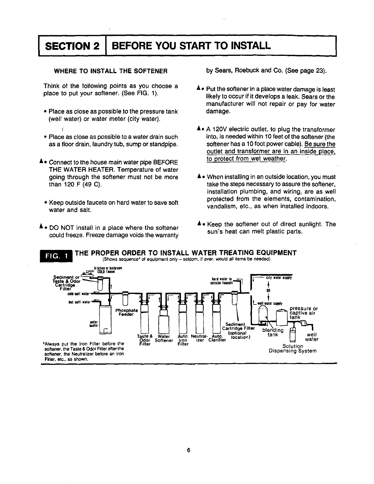
THE PROPER ORDER TO INSTALL WATER TREATING EQUIPMENT
(Showssequence* of equipment only- seldom, if ever, would all items be needed)
kitchegn_bathroom
COLDfacet
Sediment
T_3ste &
artricige
Filter
water
heater
*Always put the Iron Filter before the
softener,the Taste &Odor Filterafterthe
softener, the Neutralizer before an Iron
Filter, etc,, as shown.
Phosphate
Feeder
Taste & Water
Odor Softener
Filter
hardwater J_-- CityWaterSUpply
iL wollwaterslJpDly
|_ _ pressure or
I I I F--7 captive air
Sediment I _
Iron izer Clarifier _ water
Filter Solution
Dispensing System
ISECTION 2
i
BEFORE YOU START TO INSTALL I
PLAN HOW TO INSTALL YOUR SOFTENER
You must first decide how to run in and out pipes to
the flexible connectors* included with your softener.
Look at your house main water pipe at the point you
will connect the softener. Is the pipe soldered copper,
glued plastic, or threaded galvanized or brass? What
is the pipe size? What kind of pipe and fittings is it
easiest f(_r you to work with, and what tools do you
have?
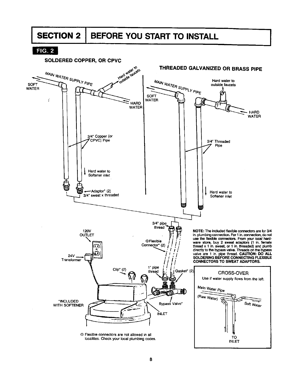
Now look at FIG. 2 on page 8 and use it as a guide to
plan what materials you will need. As you plan your in
and out piping, keep in mind the following check list.
Then get all the materials you will need before you
start.
TOOLS, PIPE, FI'I-rlNGS AND
OTHER MATERIALS YOU WILL NEED
P' In and out pipes to the softener must be at least
3/4 in. size. Some local codes may tell you to use
no less than 1 in. pipe size (See Note on page 8).
I," Use copper, brass, or galvanized pipe and fittings.
Some codes may also allow CPVC plastic pipe.
_' Copper and galvanized pipe corrode fast when
connected together. Use pipe and fittings of the
same material.
P' ALWAYS install the bypass valve, which allows
you to turn off water to the softener, but still have
water in the house pipes.
Drain hose (7/16 in. inside diameter)is needed for
valve and salt tank drains. Twenty feet of hose is
included. If more hose is needed, you can buy it at
most Sears stores, or through Sears catalog,
Stock No. 42-3433.
If a rigid valve drain is needed to comply with
plumbing codes, you can buy the parts needed
(See page 11) to change the softener to a 1/2 in.
copper tubing drain.
i,,' TOOLS NEEDED: -Common and cross point
(Phillips) screw drivers, slip-joint pliers and a tape
measure or rule. ALSO...
• . .for SOLDERED COPPER - tubing cutter,
propane torch, solid-core LEAD-FREE solder,
paste flux, emery cloth, sandpaper or steel wool.
...for THREADED PIPE- hacksaw or pipe cutter,
pipe wrenches, pipe threading tool, pipe joint
compound approved for use on potable water.
...for CPVC Plastic - hacksaw, adjustable
wrench, solvent cement approved for use on
potable water, primer.
_" You can buy adapiors to go from a copper or
threaded to CPVC.
*Flexible connectors are not allowed in some localities. Check your local plumbing codes.
ISECTION 2 I BEFORE YOU START TO INSTALL I
Idl[_lgP_I
SOLDERED COPPER, OR CPVC
SOFT
WATER
THREADED GALVANIZED OR BRASS PIPE
MAIN Hard water to
outsidefaucets
_OFT
WATER
HARD
WATER
3/4" Copper (or
CPVC_ p_e 314"Threaded
Pipe
Hard water to
Softener inlet
I.,,.---Adaptor* (2) Hard watsr to
_ I Softener inlet
3/4" pipe I
120V thread -_.-_ -L__ NOTE:The includedflexibleconnectorsare for3/4
ouTrI.tET , _I_ in.plumbingconnection,ForI in._ion, do not
--_ ...... _ F: L_e the flexibleconcectors.From your k_ hard-
"_ __e ._ /_/ware store, buy 2 sweat adapto_ (1 in. lernale
I(_11 Co_nector" (2)/ _ _ thread x 1 in. swe_d,or I in. threaded)ar',dplumb
I'_._":l "_"_,' I I1 dimcttytothebypassvatve-Threadsontheb) AYP_LL
._._IL(4J_I[ /I _ / valve are 1 in. pipe thread. CAUTION: DO A
24V _...1--_1__.__2j.__ ,i_,I SOLDERING BEFORE CONNECTING FLEXIBLE
Transforrt_r _' • / /_/CONNECTORS TO SWEAT ADAPTORS.
, 1 pipe :-''
Clip_(._2) _ thread _; _Gasket* (2: CROSS-OVER
_.- _,(_ _t_ _,_/ Use ifwatersupplyflowsfromtheleft.
-Bypass Valve" _'_ _
OFlexible connectors are not allowed in all TO
localities.Cheek your local plumbingcedes. INLET
8
JSECTION 3 J STEP BY STEP GUIDES TO INSTALL
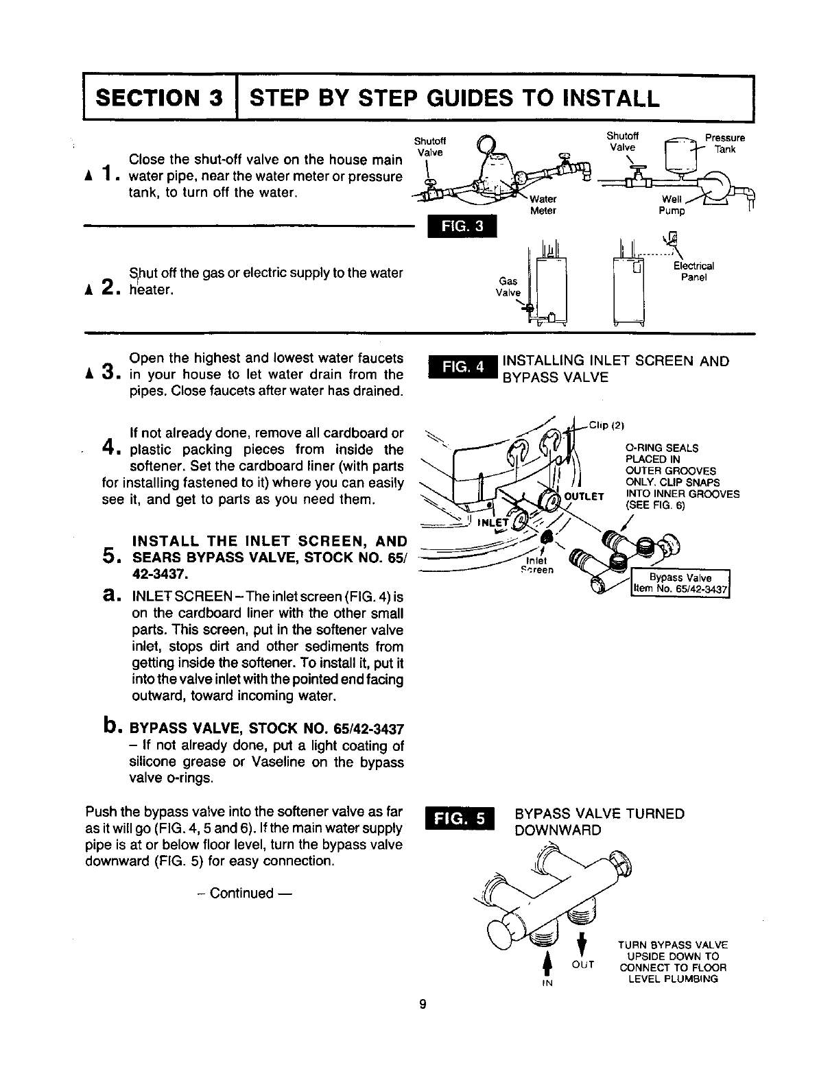
Close the shut-off valve on the house main
=1. water pipe, near the water meter or pressure
tank, to turn off the water.
Shutoff Shutoff Pressure
-- " Water Well/_
Meter Pump
SIhut off the gas or electric supply to the water
A 2, heater.
Open the highest and lowest water faucets
A3. in your house to let water drain from the
pipes. Close faucets after water has drained.
_ INSTALLING INLET SCREEN AND
BYPASS VALVE
If not already done, remove all cardboard or
4. plastic packing pieces from inside the
softener. Set the cardboard liner (with parts
for installing fastened to it) where you can easily
see it, and get to parts as you need them. OUTLET
O-RING SEALS
PLACED IN
OUTER GROOVES
ONLY, CLIP SNAPS
INTO INNER GROOVES
(SEE FIG. 6)
1
a.
INSTALL THE INLET SCREEN, AND
SEARS BYPASS VALVE, STOCK NO. 65/
42-3437.
INLET SCREEN - The inlet screen (FIG. 4) is
on the cardboard liner with the other small
parts. This screen, put in the softener valve
inlet, stops dirt and other sediments from
getting inside the softener. To install it, put it
into the valve inlet with the pointed end facing
outward, toward incoming water.
b. BYPASS VALVE, STOCK NO. 65/42-3437
- If not already done, put a light coating of
silicone grease or Vaseline on the bypass
valve o-rings.
Push the bypass valve into the softener valve as far
as it will go (FIG. 4, 5 and 6). If the main water supply
pipe is at or below floor level, turn the bypass valve
downward (FIG. 5) for easy connection.
- Continued --
BYPASS VALVE TURNED
DOWNWARD
O_U TURN BYPASS VALVE
UPSIDE DOWN TOT CONNECT TO FLOOR
IN LEVEL PLUMBING

ISECTION 3 I STEP BY STEP GUIDES TO INSTALL I
C. SNAP THE 2 LARGE HOLDING CLIPS INTO
PLACE, FROM THE TOP DOWN AS SHOWN.
BE SURE THEY SNAP FIRMLY IN PLACE, SO
THE BYPASS VALVE WILL NOT PULL OUT.
SIDE VIEW
/_CLIP
END VIEW
Bypass Valve
Valve Body (Push all the way in)
Inlet or Outlet
MOVE SOFTENER INTO PLACE
6. Movethesoftenerintoplace. Besurethesurface
it sits on is level and smooth• If needed, put a
piece of 3/4" plywood, at least 18" square under the
tank. Then put a spacer under the plywood to level
the softener.
7. CONNECT THE SOFTENER
a. Place gaskets into 1" nuts on the flexible con-
nectors (FIG. 2). Then carefully turn onto the
bypass valve and tighten•
USE CARE NOT TO CROSS-THREAD.
TIGHTEN FIRMLY, BUT DO NOT OVER-
TIGHTEN AND BREAK THEBYPASSVALVE,
OR CUT THE GASKETS.
b. Measure, cut, thread (if applies) and put together
all pipe and fittings from the main water supply
pipe, to the flexible connectors•
IMPORTANT: WHEN LOOKING AT THE FRONT
OF THE SOFTENER, THE INLET IS ON THE RIGHT
SIDE. IF WATER IN YOUR HOUSE MAIN WATER
PIPE RUNS FROM LEFT TO RIGHT (SEE PAGE 8),
BE SURE TO USE A "CROSS-OVER" AS SHOWN.
Ca
dll
When all piping fits together good...
•..solder all sweat copper joints following tips
on page 29.
•..solvent cement all CPVC joints.
...thread together and tighten all threaded
joints, using Teflon tape or pipe joint compound.
Use Teflon tape or pipe joint compound and turn
the 3/4" end of the flexible connectors onto the
plumbing just installed. DOUBLE-CHECK TO
BE SURE RAW, HARD WATER IS PIPED TO
THE SOFTENER INLET.
10
JSECTION 3 J STEP BY STEP GUIDES TO INSTALL
Grommet
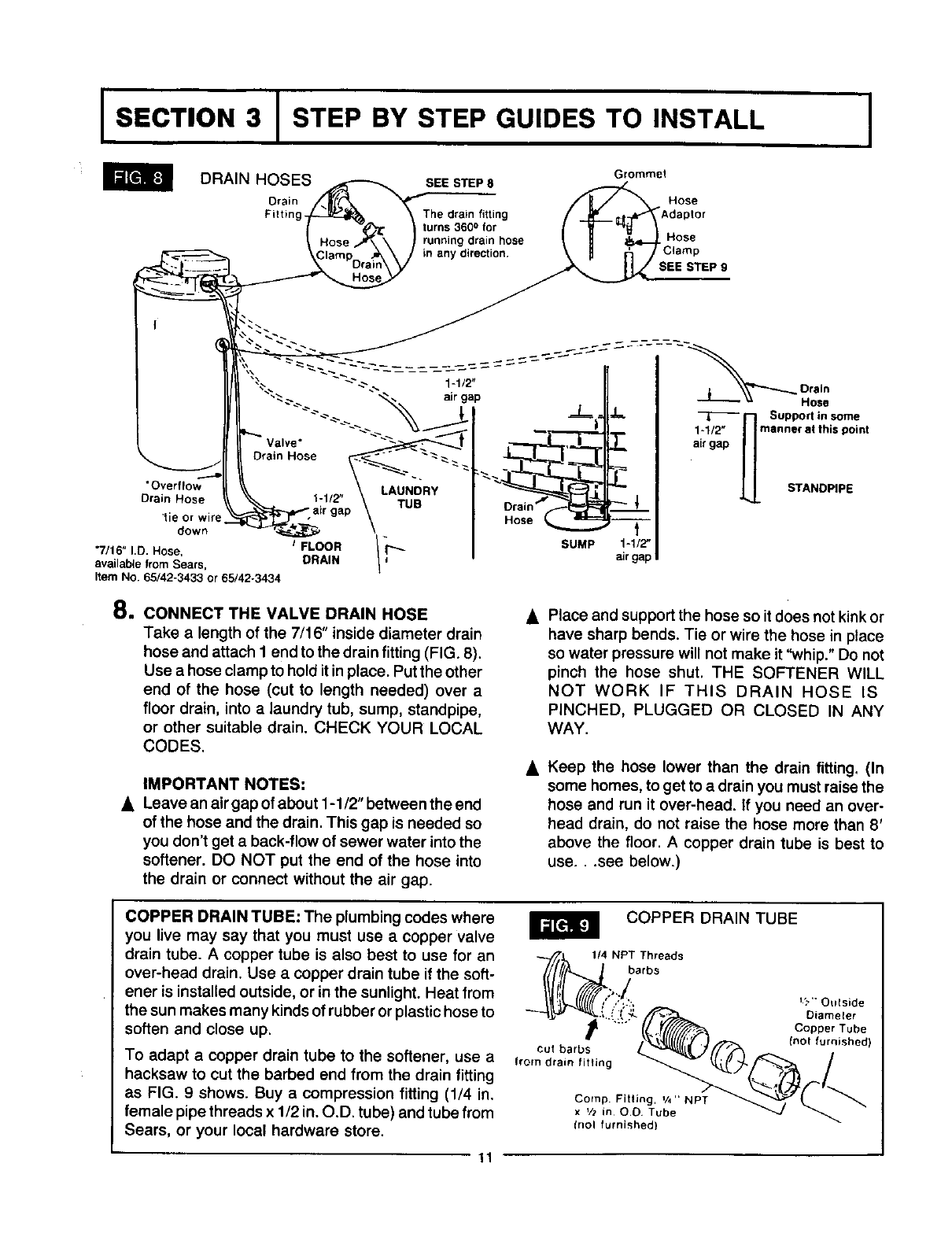
DRAIN HOSES SEESTEP8
Drain Hose
Filtin The drain fitting "Adaplor
turns 3600 for
running drain hose Hose
in any direction. SEE STEP 9
I
Drain Hose
"Overflow LAUNDRY
Drain Hose 1-1/2" TUB
tie or wire
down
"7/16" I.D. Hose, JFLOOR / I''-
available from Sears, DRAIN
Item No. 65/42-3433 or 65/42o3434
Hose f
SUMP 1-1/2"
air gap
8. CONNECT THE VALVE DRAIN HOSE
Take a length of the 7/16" inside diameter drain
hose and attach I end to the drain fitting (FIG. 8).
Use a hose clamp to hold itin place. Put the other
end of the hose (cut to length needed) over a
floor drain, into alaundry tub, sump, standpipe,
or other suitable drain. CHECK YOUR LOCAL
CODES.
IMPORTANT NOTES:
Leave an air gap of about 1-1/2" between the end
of the hose and the drain. This gap is needed so
you don't get a back-flow of sewer water into the
softener. DO NOT put the end of the hose into
the drain or connect without the air gap.
Place and support the hose so it does not kink or
have sharp bends. Tie or wire the hose in place
so water pressure will not make it "whip." Do not
pinch the hose shut. THE SOFTENER WILL
NOT WORK IF THIS DRAIN HOSE IS
PINCHED, PLUGGED OR CLOSED IN ANY
WAY.
Keep the hose lower than the drain fitting. (In
some homes, to get to a drain you must raise the
hose and run it over-head. If you need an over-
head drain, do not raise the hose more than 8'
above the floor. A copper drain tube is best to
use...see below.)
COPPER DRAIN TUBE: The plumbing codes where
you live may say that you must use a copper valve
drain tube. A copper tube is also best to use for an
over-head drain. Use a copper drain tube if the soft-
ener is installed outside, or in the sunlight. Heat from
the sun makes many kinds of rubber or plastic hose to
soften and close up,
To adapt acopper drain tube to the softener, use a
hacksaw to cut the barbed end from the drain fitting
as FIG. 9 shows. Buy a compression fitting (1/4 in.
female pipe threads x 1/2 in. O.D. tube) and tube from
Sears, or your local hardware store.
COPPER DRAIN TUBE
_/,_ 1,; NPbTaTh_eads
.... Copper Tube
t ,no o,sbod,
CUt barbs L. _,/(/_f_ =__ n
from drain fitting _ _(._L_'_ /
x11_in oe _ube -" ' _J _ _"
(noI furnished)
11
I SECTION 3 ISTEP BY STEP GUIDES TO INSTALL I
CONNECT A SALT TANK OVERFLOW
9. HOSE it in place. Put the other end of the hose over the
floor drain.
a. Take the rubber grommet, hose adaptor and
hose clamp (FIG. 8) that are on the small parts
cardboard liner.
b, Push the grommet into the hole in the salt tank
walltso half is inside and half is outside.
C, Push the bigger end of the hose adaptor into the
grommet.
d, Push one end of a length of 7/16" I.D. hose onto
the hose adaptor, using the hose clamp to hold
IMPORTANT NOTES:
•The salt tank overflow is for safety only. Ifthesalt
tank should overfill with water, the overflow hose
carries it to the drain.
Over-fill water must run downward through the
hose. Do not raise the hose higher than the
grommet and hose adaptor (FIG. 8).
DO NOT connect to the valv_ drain hose you
installed in step 9. A separate hose is needed for
both drains.
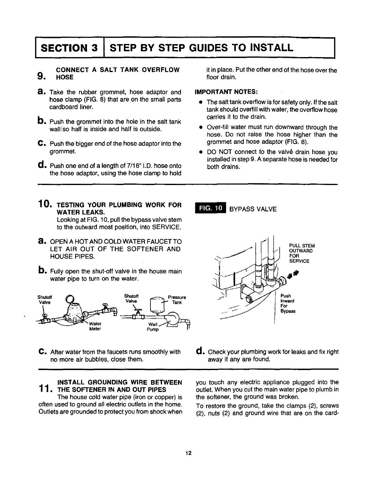
10. TESTING YOUR PLUMBING WORK FOR
WATER LEAKS.
Looking at FIG. 10, pull the bypass valve stem
to the outward most position, into SERVICE.
a, OPEN A HOT AND COLD WATER FAUCET TO
LET AIR OUT OF THE SOFTENER AND
HOUSE PIPES.
b, Fully open the shut-off valve in the house main
water pipe to turn on the water.
Shutoff _1 Shutoff Pressure
_ "Water We_l_
Meter Pump
BYPASS VALVE
PULL STEM
OUTWARD
FOR
SERVICE
4 °
%*, 'J Push
Inward
Bypass
C. After water from the faucets runs smoothly with
no more air bubbles, close them.
d • Check your plumbing work for leaks and fix right
away if any are found.
INSTALL GROUNDING WIRE BETWEEN
11•THE SOFTENER IN AND OUT PIPES
The house cold water pipe (iron or copper) is
often used to ground a!l electric outlets in the home.
Outlets are grounded to protect you from shock when
you touch any electric appliance plugged into the
outlet. When you cut the main water pipe to plumb in
the softener, the ground was broken.
To restore the ground, take the clamps (2), screws
(2), nuts (2) and ground wire that are on the card-
12
ISECTION 3 I STEP BY STEP GUIDES TO INSTALL I
board liner. Install across the iron orcopper in and out
pipes as shown in FIG. 11. Be sure good contact is
made between the pipe and the clamps. Fasten the
ground wire tightly between the clamps.
IMPORTANT: Be sure the cold water pipe has direct
metal to metal contact all the way to the ground.
Plastic, rubber or other electrically insulating parts
such as hoses, fittings, washers or gaskets can break
the direct metal to metal contact. Also check the
water meter (city water) or the well pump. Install #4
copper jumper wires, clamped tightly on both ends,
across insulated parts (FIG. 12).
COLD WATER PIPE GROUND
Ground
Wire
From
Valve TO
Outlet Valve
Inlet
WATER METER JUMPER WIRE
Water Meter
#4 Oroundwlre
ELECTRIC POWER OUTLET FOR YOUR
12. sOFrENER
The softener works on 24 volt, 60 Hz electric
power. The included transformer changes standard
120 volt AC house power to 24 volts. You must plug
the transformer into a 120 volt outlet only. Be sure the
outlet is always "live", so someone cannot turn it off
by mistake.
NOTE: The included transformer is made for inside
use only. Be sure the electrical outlet you plug the
transformer into is inside, to protect from weather
(see page 6).
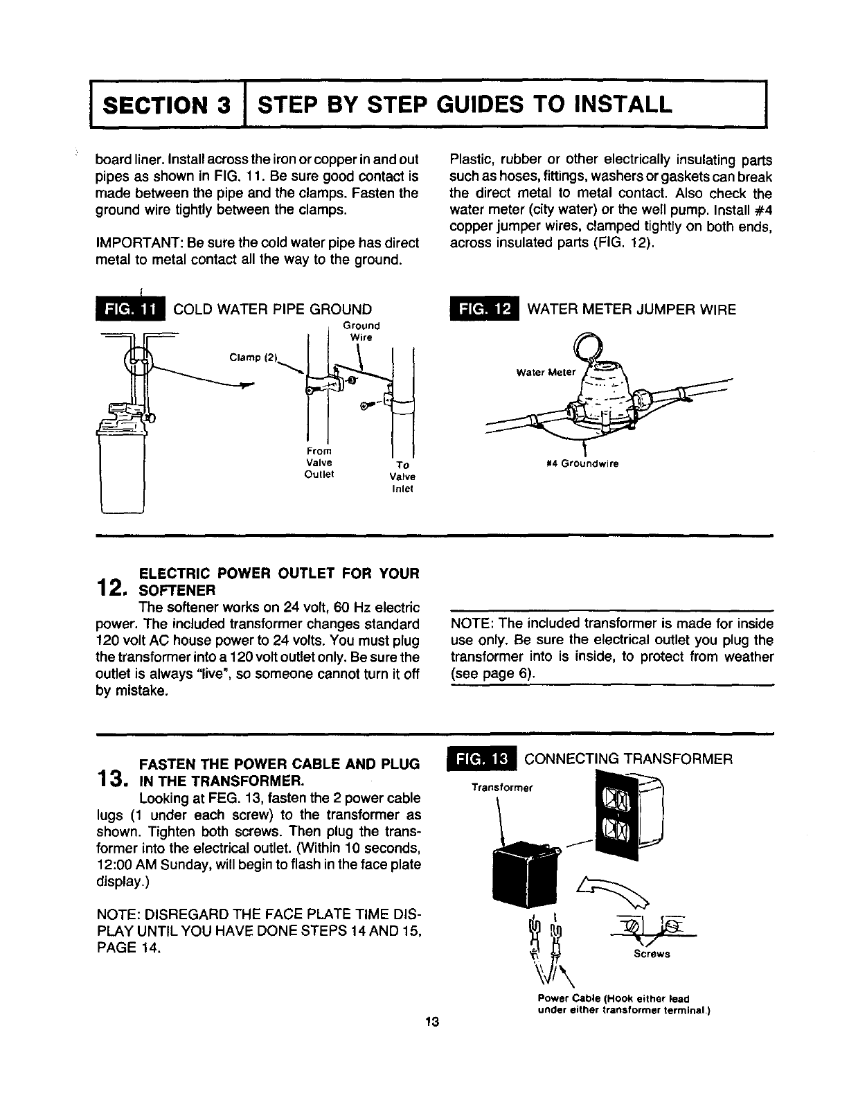
FASTEN THE POWER CABLE AND PLUG
13. IN THE TRANSFORMER.
Looking at FEG. 13, fasten the 2 power cable
lugs (1 under each screw) to the transformer as
shown. Tighten both screws. Then plug the trans-
former into the electrical outlet. (Within 10 seconds,
12:00 AM Sunday, will begin to flash in the face plate
display.)
NOTE: DISREGARD THE FACE PLATE TIME DIS-
PLAY UNTIL YOU HAVE DONE STEPS 14 AND 15,
PAGE 14.
13
CONNECTING TRANSFORMER
Transformer
_,_ Screws
Power Cable (Hook either lead
under either transformer terminal.)
ISECTION 3 i STEP BY STEP GUIDES TO INSTALL
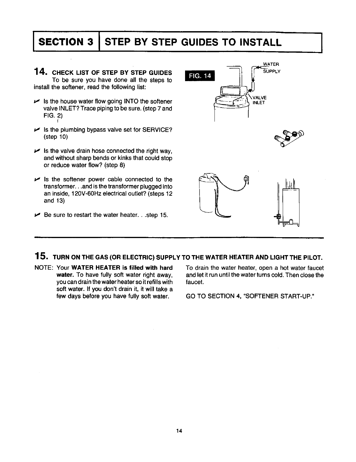
14. CHECK LIST OF STEP BY STEP GUIDES
To be sure you have done all the steps to
install the softener, read the following list:
Is the house water flow going INTO the softener
valve INLET? Trace piping to be sure. (step 7 and
FIG. 2)
f
Is the plumbing bypass valve set for SERVICE?
(step 10)
P" Is the valve drain hose connected the right way,
and without sharp bends or kinks that could stop
or reduce water flow? (step 8)
P" Is the softener power cable connected to the
transformer...and is the transformer plugged into
an inside, 120V-60Hz electrical outlet? (steps 12
and 13)
I," Be sure to restart the water heater...step 15.
WATER
ilNALLVTE'_41"_UUPPLY
I
15. TURN ON THE GAS (OR ELECTRIC) SUPPLY TO THE WATER HEATER AND LIGHT THE PILOT.
NOTE: Your WATER HEATER is filled with hard
water. To have fully soft water right away,
you can drain the water heater so itrefills with
soft water. If you don't drain it, it will take a
few days before you have fully soft water.
To drain the water heater, open a hot water faucet
and let it run until the water turns cold. Then close the
faucet.
GO TO SECTION 4, "SOFTENER START-UP."
14
I
PLEASE GO TO SECTION 4, PAGE 16, "SOFTENER START-UP."
15
I SECTION 4 IWATER SOFTENER START-UP I
SANITIZE THE SOFTENER, SET THE TIMER, AND
FILL WITH SALT TO COMPLETE INSTALLATION.
SANITIZING THE WATER SOFTENER
1. Care is taken at the factory to keep your water
softener clean and sanitary. Materials used to
make the softener will not infect or contaminate your
water supply, and will not cause bacteria to form or
grow. However, during shipping, storage, installing
and operating, bacteria could get into the water
softener. For this reason, sanitizing as foltows is
suggestedO when installing.
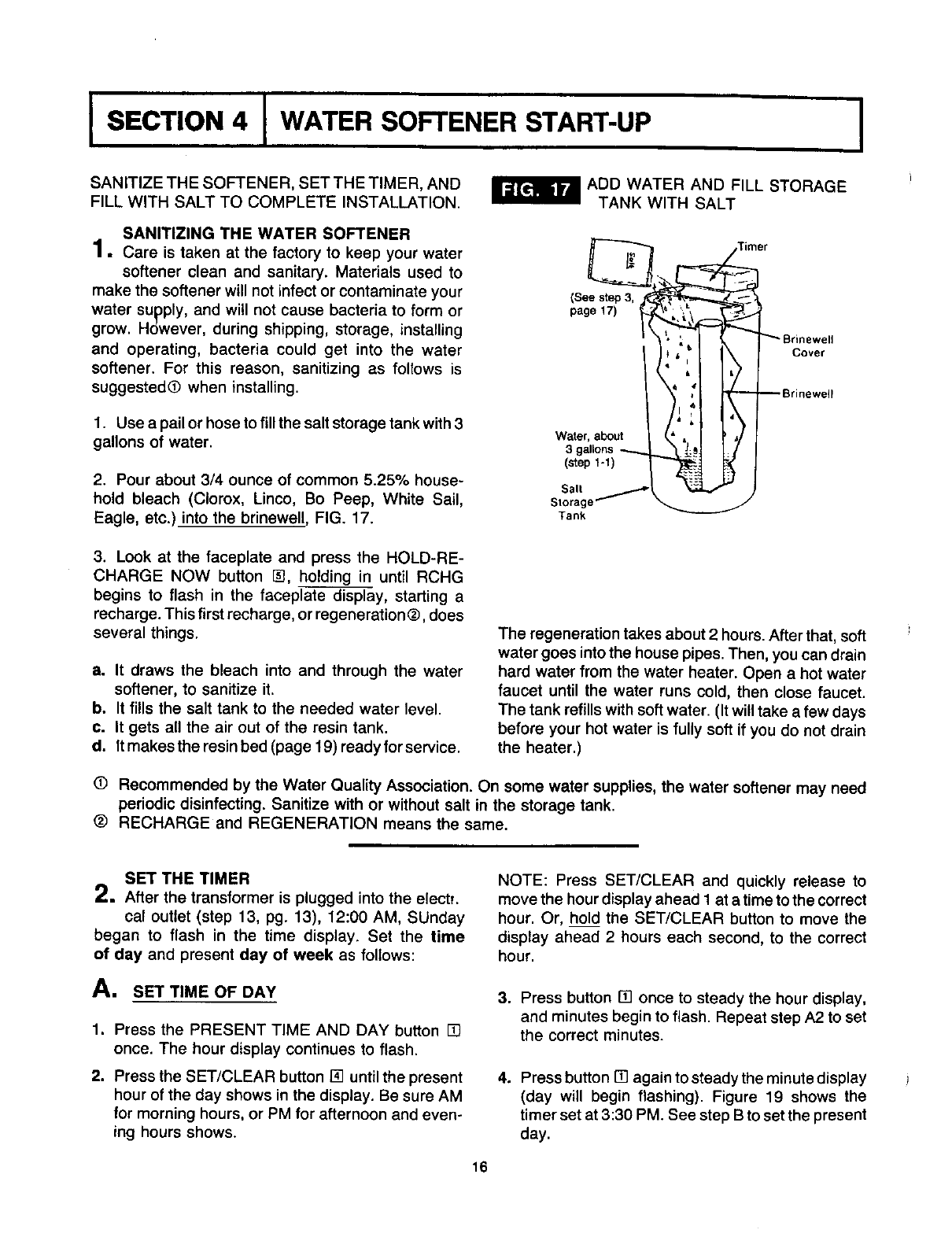
1. Use a pail or hose to fill the salt storage tank with 3
gallons of water.
2. Pour about 3/4 ounce of common 5.25% house-
hold bleach (Clorox, Linco, Bo Peep, White Sail,
Eagle, etc.) into the brinewell, FIG. 17.
ADD WATER AND FILL STORAGE
TANK WITH SALT
Timer
(s p , j__
page 17) _
_! t _ Srinewell
Cover
Brinewell
Salt
Storage
Tank
3. Look at the faceplate and press the HOLD-RE-
CHARGE NOW button @, holding in until RCHG
begins to flash in the faceplate display, starting a
recharge. This first recharge, or regeneration ®, does
several things.
a. It draws the bleach into and through the water
softener, to sanitize it.
b. It fills the salt tank to the needed water level.
c. It gets all the air out of the resin tank.
d. It makes the resin bed (page 19) ready for service.
The regeneration takes about 2 hours. After that, soft
water goes into the house pipes. Then, you can drain
hard water from the water heater. Open a hot water
faucet until the water runs cold, then close faucet.
The tank refills with soft water. (It will take a few days
before your hot water is fully soft if you do not drain
the heater.)
(D Recommended by the Water Quality Association. On some water supplies, the water softener may need
periodic disinfecting. Sanitize with or without salt in the storage tank.
® RECHARGE and REGENERATION means the same.
SET THE TIMER
2. After the transformer is plugged into the elects,
cal outlet (step 13, pg. 13), 12:00 AM, SUnday
began to flash in the time display. Set the time
of day and present day of week as follows:
A. SET TIME OF DAY
1. Press the PRESENT TIME AND DAY button []
once. The hour display continues to flash.
2. Press the SET/CLEAR button [] until the present
hour of the day shows in the display. Be sure AM
for morning hours, or PM for afternoon and even-
ing hours shows.
NOTE: Press SET/CLEAR and quickly release to
move the hour display ahead 1 at a time to the correct
hour. Or, hold the SET/CLEAR button to move the
display ahead 2 hours each second, to the correct
hour.
3. Press button [] once to steady the hour display,
and minutes begin to flash. Repeat step A2 to set
the correct minutes.
4. Press button [] againtosteadytheminutedisplay
(day will begin flashing). Figure 19 shows the
timer set at 3:30 PM. See step B to set the present
day.
16
ISECTION 4 IWATER SOFTENER START-UP
Kenlnnloro
disptay buttons
RESENT TIME AND DAY
[] RECHARGE TIME
[] RECHARGE DAY
] [] SET/CLEAR
elma iNite A,mWdlNnk=
[] ON/OFF VACATION
HOLD RECHARGE NOW
k
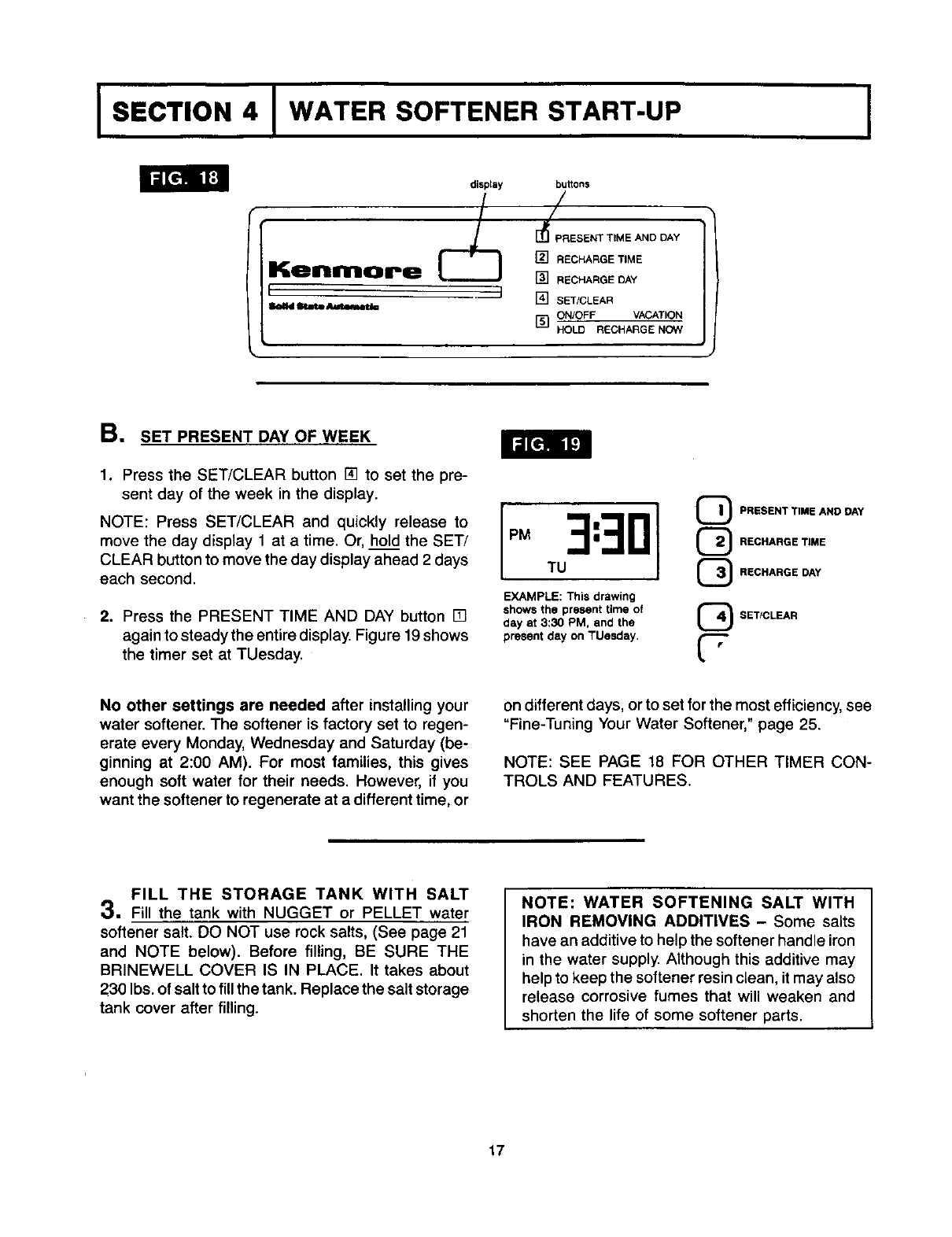
B. SET PRESENT DAY OF WEEK
1. Press the SET/CLEAR button [] to set the pre-
sent day of the week in the display.
NOTE: Press SET/CLEAR and quickly release to
move the day display 1 at a time. Or, hold the SET/
CLEAR button to move the day display ahead 2 days
each second.
2. Press the PRESENT TIME AND DAY button []
again to steady the entire display Figure 19shows
the timer set at TUesday.
U I GPRESENT TIME AND DAY
PM 3: @RECHARGE TIME
TU @RECHARGE DAY
EXAMPLE: This drawing
shows the present time of
day at 3:30 PM, and the
present day on TUesday, t"-"
L"
SETICLEAR
No other settings are needed after installing your
water softener. The softener is factory set to regen-
erate every Monday, Wednesday and Saturday (be-
ginning at 2:00 AM). For most families, this gives
enough soft water for their needs. However, if you
want the softener to regenerate at a different time, or
on different days, or to set for the most efficiency, see
"Fine-Tuning Your Water Softener," page 25.
NOTE: SEE PAGE 18 FOR OTHER TIMER CON-
TROLS AND FEATURES.
FILL THE STORAGE TANK WITH SALT
3, Fill the tank with NUGGET or PELLET water
softener salt. DO NOT use rock salts, (See page 21
and NOTE below). Before filling, BE SURE THE
BRINEWELL COVER IS IN PLACE. It takes about
230 Ibs. of salt to fill the tank. Replace the salt storage
tank cover after filling.
NOTE: WATER SOFTENING SALT WITH
IRON REMOVING ADDITIVES - Some salts
have an additive to help the softener handle iron
in the water supply. Although this additive may
help to keep the softener resin clean, it may also
release corrosive fumes that will weaken and
shorten the life of some softener parts.
17
I SECTION 5 IHOW YOUR WATER SOFTENER WORKS I
OTHER TIMER CONTROL
BUTTONS AND FEATURES
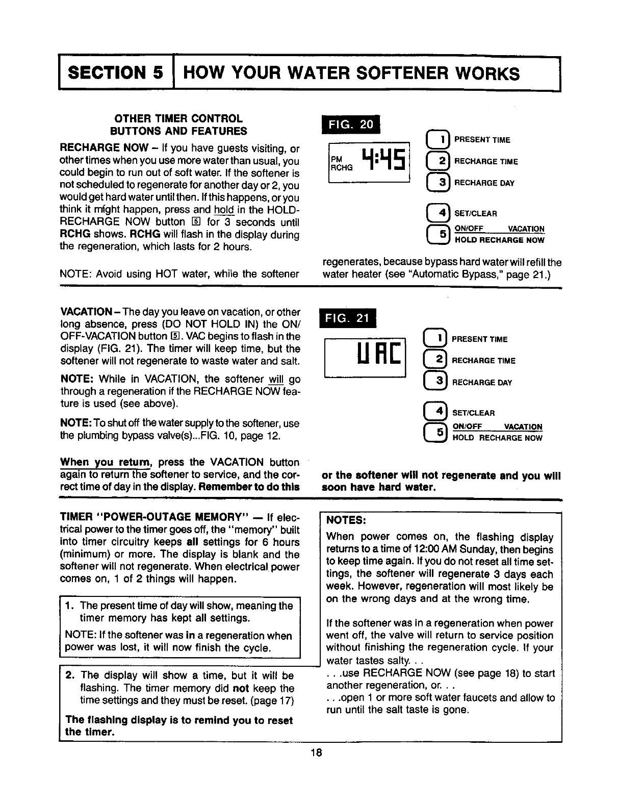
RECHARGE NOW - If you have guests visiting, or
other times when you use more water than usual, you
could begin to run out of soft water. If the softener is
not scheduled to regenerate for another day or 2, you
would get hard water untilthen. Ifthis happens, or you
think it might happen, press and hold in the HOLD-
RECHARGE NOW button [] for 3 seconds until
RCHG shows. RCHG will flash in the display during
the regeneration, which lasts for 2hours.
NOTE: Avoid using HOT water, while the softener
QRESENT TIME
(_ RECHARGE TIME
(_ RECHARGE DAY
SET/CLEAR
ON/OFF VACATION
HOLD RECHARGE NOW
regenerates, because bypass hard water will refill the
water heater (see "Automatic Bypass," page 21 .)
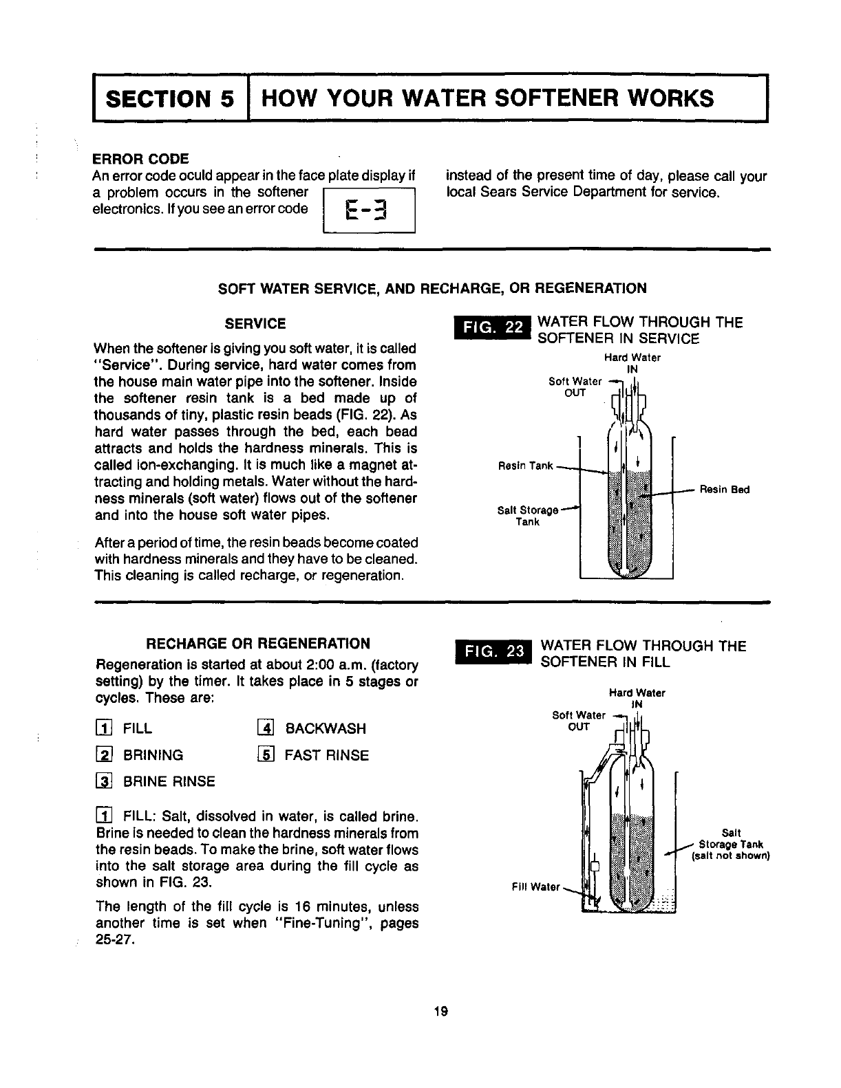
VACATION - The day you leave on vacation, or other
long absence, press (DO NOT HOLD IN) the ON/
OFF-VACATION button I_. VAC begins to flash in the
display (FIG. 21). The timer will keep time, but the
softener will not regenerate to waste water and salt.
NOTE: While in VACATION, the softener will go
through a regeneration if the RECHARGE NOW fea-
ture is used (see above).
NOTE: To shutoff the water supply to the softener, use
the plumbing bypass valve(s)...FIG. 10, page 12.
When you return, press the VACATION button
again to return the softener to service, and the cor-
rect time of day in the display. Remember to do this
unr]
_RESENT TIME
(_ RECHARGE TIME
(_ RECHARGE DAY
_ET/CLEAR
(_ ONIOFF VACATION
HOLD RECHARGE NOW
or the softener will not regenerate and you will
soon have hard water.
TIMER "POWER-OUTAGE MEMORY" -- If elec-
trical power to the timer goes off, the "memory" built
into timer circuitry keeps all settings for 6 hours
(minimum) or more. The display is blank and the
softener will not regenerate• When electrical power
comes on, 1 of 2 things will happen•
1. The present time of day will show, meaning the I
timer memory has kept all settings. I
NOTE: If the softener was in a regeneration when
power was lost, it will now finish the cycle.
2. The display will show atime, but it will be
flashing• The timer memory did not keep the
time settings and they must be reset. (page 17)
The flashing display is to remind you to reset
the timer.
NOTES:
When power comes on, the flashing display
returns to a time of 12:00 AM Sunday, then begins
to keep time again• If you do not reset all time set-
tings, the softener will regenerate 3 days each
week. However, regeneration will most likely be
on the wrong days and at the wrong time.
If the softener was in a regeneration when power
went off, the valve will return to service position
without finishing the regeneration cycle. If your
water tastes salty•..
•..use RECHARGE NOW (see page 18) to start
another regeneration, or...
•..open 1 or more soft water faucets and allow to
run until the salt taste is gone.
18
I SECTION 5 [HOW YOUR WATER SOFTENER WORKS
ERROR CODE
An error code oculd appear in the face plate display if
a problem occurs in the softener
electronics. Ifyou see an error code I_ _
LL
instead of the present time of day, please call your
local Sears Service Department for service.
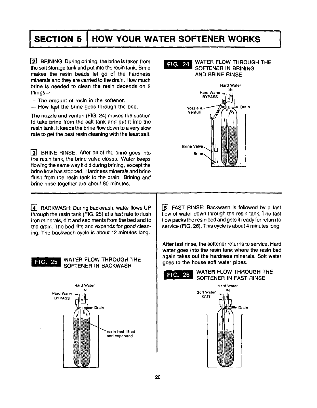
SOFT WATER SERVICE, AND
SERVICE
When the softener is giving you soft water, it is called
"Service". During service, hard water comes from
the house main water pipe into the softener. Inside
the softener resin tank is a bed made up of
thousands of tiny, plastic resin beads (FIG. 22). As
hard water passes through the bed, each bead
attracts and holds the hardness minerals. This is
called ion-exchanging. It is much like a magnet at-
tracting and holding metals. Water without the hard-
ness minerals (soft water) flows out of the softener
and into the house soft water pipes.
After a period of time, the resin beads become coated
with hardness minerals and they have to be cleaned.
This cleaning is called recharge, or regeneration.
RECHARGE, OR REGENERATION
WATER FLOW THROUGH THE
SOFTENER IN SERVICE
Hard Water
IN
Soft Water
OUT
Tank
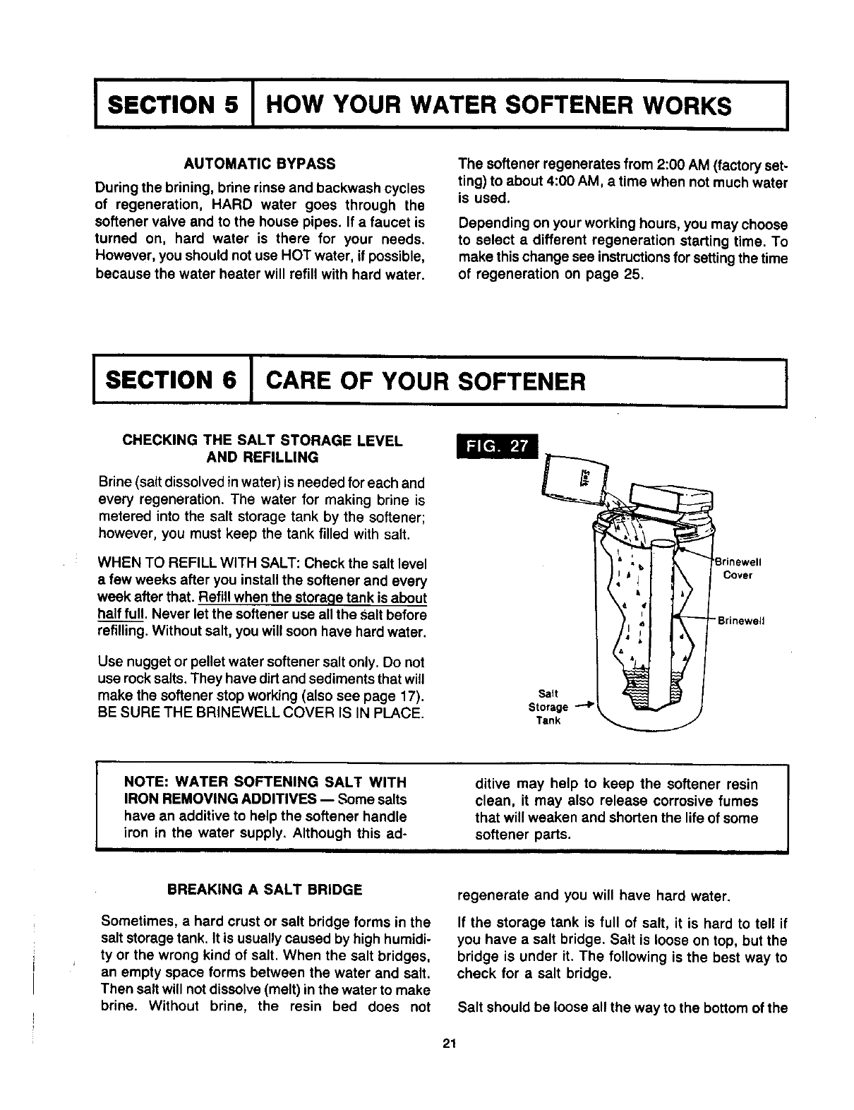
RECHARGE OR REGENERATION
Regeneration is started at about 2:00 a.m. (factory
setting) by the timer. It takes place in 5 stages or
cycles. These are:
[] FILL
[] BRINING
[] BRINE RINSE
[] BACKWASH
[] FAST RINSE
[] FILL: Salt, dissolved in water, is called brine.
Brine is needed to clean the hardness minerals from
the resin beads. To make the brine, soft water flows
into the salt storage area during the fill cycle as
shown in FIG. 23.
The length of the fill cycle is 16 minutes, unless
another time is set when "Fine-Tuning", pages
25-27.
WATER FLOW THROUGH THE
SOFTENER IN FILL
HardWater
IN
Soft Water
OUT
Salt
Storage Tank
19
ISECTION 5 IHOW YOUR WATER SOFTENER WORKS
[] BRINING: During brining, the brine is taken from
the salt storage tank and put into the resin tank. Brine
makes the resin beads let go of the hardness
minerals and they are carded to the drain. How much
brine is needed to clean the resin depends on 2
thingsw
-- The amount of resin in the softener.
-- How fast the brine goes through the bed.
The nozzle and venturi (FIG. 24) makes the suction
to take brine from the salt tank and put it into the
resin tank. It keeps the brine flow down to a very slow
rate to get the best resin cleaning with the least salt.
[] BRINE RINSE: After all of the brine goes into
the resin tank, the brine valve closes. Water keeps
flowing the same way it did during brining, except the
brine flow has stopped. Hardness minerals and brine
flush from the resin tank to the drain. Brining and
brine rinse together are about 80 minutes.
WATER FLOW THROUGH THE
SOFTENER IN BRINING
AND BRINE RINSE
Hard Wafer
IN
Hard Water.
BYPASS
r_ Drain
Venturi
Brine Valve _,
Brine_
[] BACKWASH: During backwash, water flows UP
through the resin tank (FIG. 25) at a fast rate to flush
iron minerals, dirt and sediments from the bed and to
the drain. The bed lifts and expands for good clean-
ing. The backwash cycle is about 12 minutes long,
WATER FLOW THROUGH THE
SOFTENER IN BACk'3NASH
Hard Water
IN
Hard Water -
BYPASS
bed lifted
and expanded
[] FAST RINSE: Backwash is followed by afast
flow of water down through the resin tank. The fast
flow packs the resin bed and gets it ready for return to
service (FIG. 26). This cycle is about 4 minutes long.
After fast rinse, the softener returns to service. Hard
water goes into the resin tank where the resin bed
again takes out the hardness minerals. Soft water
goes to the house soft water pipes.
WATER FLOW THROUGH THE
SOFTENER IN FAST RINSE
Hard Water
IN
Soft Water
OUT
2O
I SECTION 5 I HOW YOUR WATER SOFTENER WORKS I
AUTOMATIC BYPASS
During the brining, brine rinse and backwash cycles
of regeneration, HARD water goes through the
softener valve and to the house pipes. If a faucet is
turned on, hard water is there for your needs.
However, you should not use HOT water, if possible,
because the water heater will refill with hard water.
The softener regenerates from 2:00 AM (factory set-
ting) to about 4:00 AM, a time when not much water
is used.
Depending on your working hours, you may choose
to select a different regeneration starting time. To
make this change see instructions for setting the time
of regeneration on page 25.
I SECTION 6 I CARE OF YOUR SOFTENER I
CHECKING THE SALT STORAGE LEVEL
AND REFILLING
Brine (salt dissolved in water) is needed for each and
every regeneration. The water for making brine is
metered into the salt storage tank by the softener;
however, you must keep the tank filled with salt.
WHEN TO REFILL WITH SALT: Check the salt level
afew weeks after you install the softener and every
week after that. Refill when the storage tank is about
half full. Never let the softener use all the Salt before
refilling. Without salt, you will soon have hard water.
Use nugget or pellet water softener salt only. Do not
use rock salts. They have dirt and sediments that will
make the softener stop working (also see page 17).
BE SURE THE BRINEWELL COVER IS IN PLACE.
Salt
Storage
Tank
Cover
"Brinewell
NOTE: WATER SOFTENING SALT WITH
IRON REMOVING ADDITIVES -- Some salts
have an additive to help the softener handle
iron in the water supply, Although this ad-
ditive may help to keep the softener resin
clean, it may also release corrosive fumes
that will weaken and shorten the life of some
softener parts.
BREAKING A SALT BRIDGE
Sometimes, ahard crust or salt bridge forms in the
salt storage tank. It is usually caused by high humidi-
ty or the wrong kind of salt. When the salt bridges,
an empty space forms between the water and salt.
Then salt will not dissolve (melt) in the water to make
brine. Without brine, the resin bed does not
regenerate and you will have hard water.
If the storage tank is full of salt, it is hard to tell if
you have a salt bridge. Salt is loose on top, but the
bridge is under it. The following is the best way to
check for a salt bridge.
Salt should be loose all the way to the bottom of the
21
ISECTION 6 I CARE OF YOUR SOFTENER I
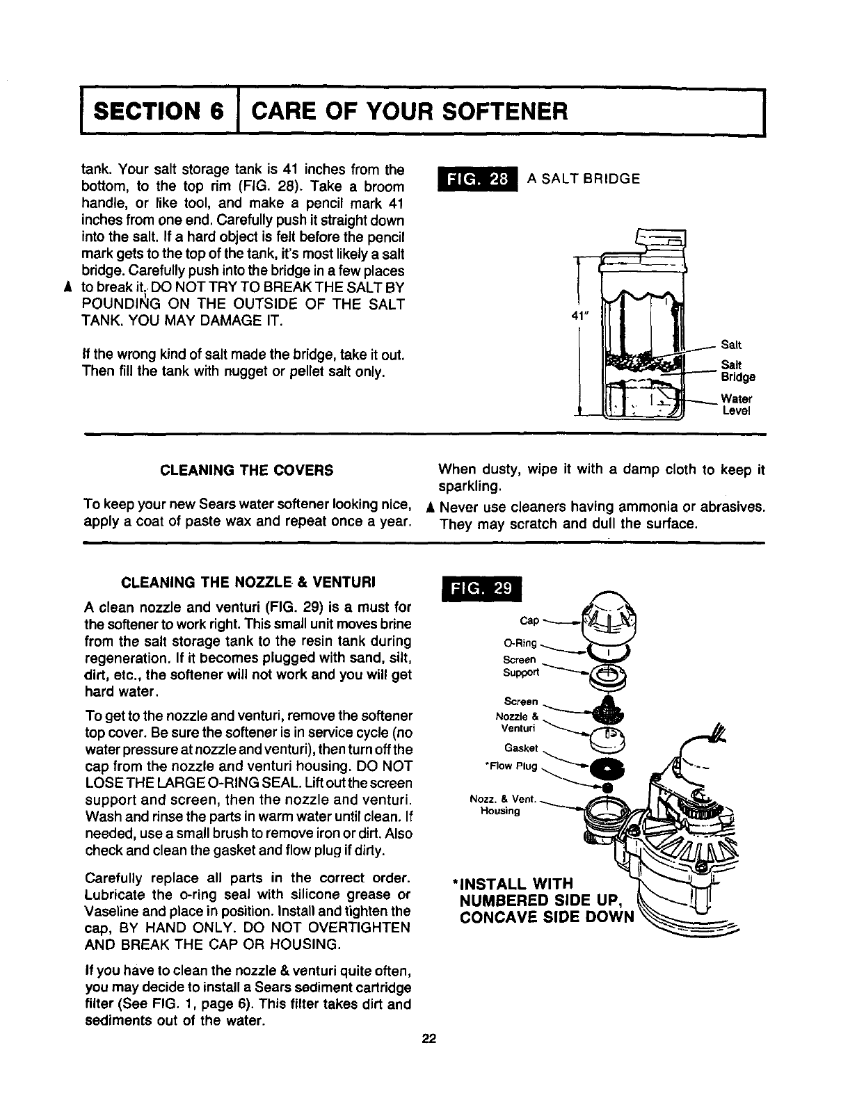
tank. Your salt storage tank is 41 inches from the
bottom, to the top rim (FIG. 28). Take a broom
handle, or like tool, and make a pencil mark 41
inches from one end. Carefully push it straight down
into the salt. If a hard object is felt before the pencil
mark gets to the top of the tank, it's most likely a salt
bddge. Carefully push into the bridge in a few places
A to break it.. DO NOT TRY TO BREAK THE SALT BY
POUNDII_IG ON THE OUTSIDE OF THE SALT
TANK. YOU MAY DAMAGE IT.
If the wrong kind of salt made the bridge, take it out.
Then fill the tank with nugget or pellet salt only.
A SALT BRIDGE
41"
......--- Salt
Salt
"--- Bridge
---4._ Water
Level
CLEANING THE COVERS
To keep your new Sears water softener looking nice,
apply a coat of paste wax and repeat once a year.
When dusty, wipe it with a damp cloth to keep it
sparkling.
A Never use cleaners having ammonia or abrasives.
They may scratch and dull the surface.
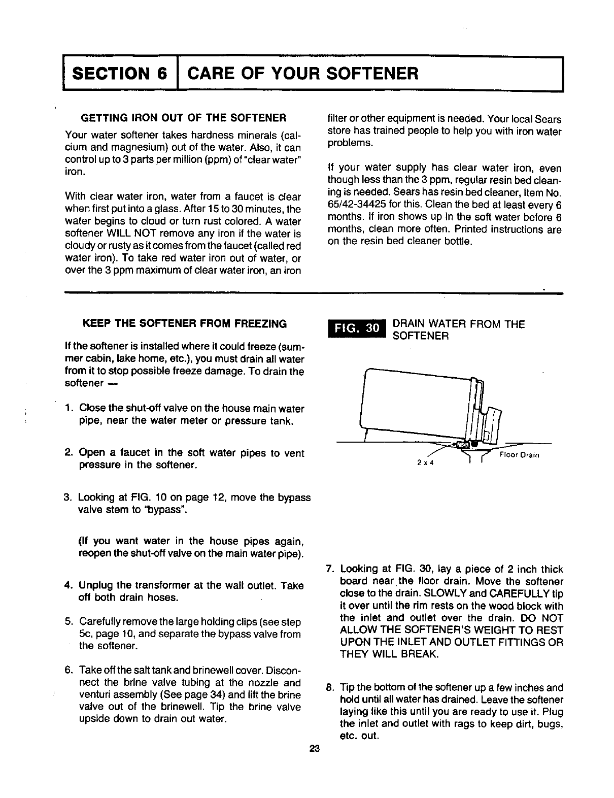
CLEANING THE NOZZLE. & VENTURI
Aclean nozzle and venturi (FIG. 29) is a must for
the softener to work right. This small unit moves brine
from the salt storage tank to the resin tank during
regeneration, If it becomes plugged with sand, silt,
dirt, etc., the softener will not work and you will get
hard water.
To get to the nozzle and venturi, remove the softener
top cover. Be sure the softener is in service cycle (no
water pressure at nozzle and venturi), then turn off the
cap from the nozzle and venturi housing. DO NOT
LOSE THE LARG E O-RING SEAL. Liftout the screen
support and screen, then the nozzle and venturi.
Wash and rinse the parts inwarm water until clean. If
needed, use a small brush to remove iron or dirt. Also
check and clean the gasket and flow plug ifdirty.
Carefully replace all parts in the correct order.
Lubricate the o-ring seal with silicone grease or
Vaseline and place in position. Install and tighten the
cap, BY HAND ONLY. DO NOT OVERTIGHTEN
AND BREAK THE CAP OR HOUSING.
If you have to clean the nozzle &venturi quite often,
you may decide to install a Sears sediment cartridge
filter (See FIG. 1, page 6). This filter takes dirt and
sediments out of the water.
*INSTALL WITH
NUMBERED SIDE UP,
CONCAVE SIDE DOWN
22
ISECTION 6 ICARE OF YOUR SOFTENER
GETTING IRON OUT OF THE SOFTENER
Your water softener takes hardness minerals (cal-
cium and magnesium) out of the water. Also, it can
control up to 3 parts per million (ppm) of"clearwater"
iron.
With clear water iron, water from a faucet is clear
when first put into a glass. After 15 to 30 minutes, the
water begins to cloud or turn rust colored. A water
softener WILL NOT remove any iron if th e water is
cloudy or rusty as it comes from the faucet (called red
water iron). To take red water iron out of water, or
over the 3 ppm maximum of clear water iron, an iron
filter or other equipment is needed. Your local Sears
store has trained people to help you with iron water
problems.
If your water supply has clear water iron, even
though less than the 3 ppm, regular resin bed clean-
ing is needed. Sears has resin bed cleaner, Item No.
65/42-34425 for this. Clean the bed at least every 6
months. If iron shows up in the soft water before 6
months, clean more often. Printed instructions are
on the resin bed cleaner bottle.
KEEP THE SOFTENER FROM FREEZING
If the softener is installed where it could freeze (sum-
mer cabin, lake home, etc.), you must drain all water
from it to stop possible freeze damage. To drain the
softener --
1. Close the shut-off valve on the house main water
pipe, near the water meter or pressure tank.
2. Open a faucet in the soft water pipes to vent
pressure in the softener.
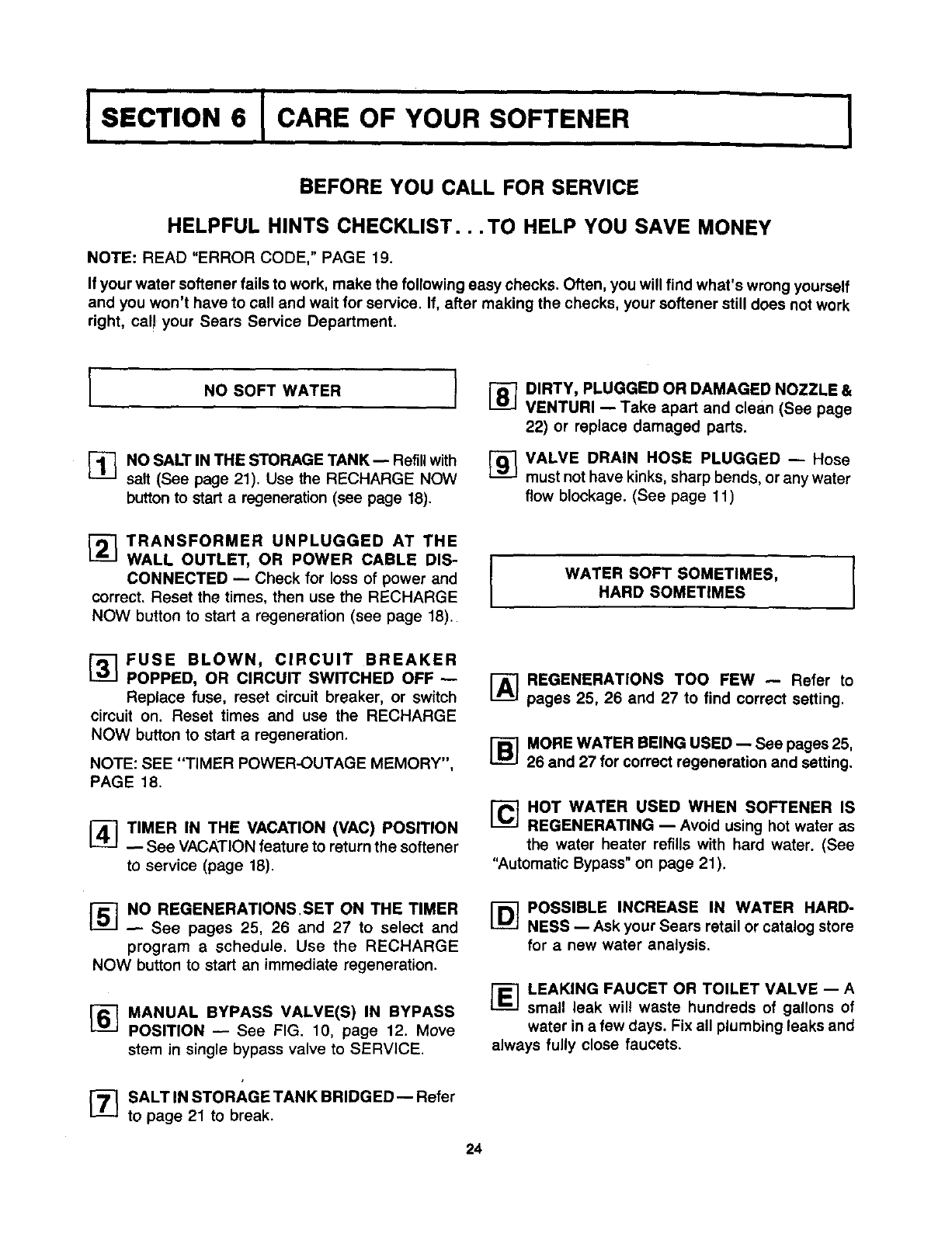
DRAIN WATER FROM THE
SOFTENER
2x4
3. Looking at FIG. 10 on page 12, move the bypass
valve stem to "bypass".
(If you want water in the house pipes again,
reopen the shut-off valve on the main water pipe).
4. Unplug the transformer at the wall outlet. Take
off both drain hoses.
5. Carefully remove the large holding clips (see step
5c, page 10, and separate the bypass valve from
the softener.
6. Take off the salt tank and brinewell cover. Discon-
nect the brine valve tubing at the nozzle and
venturi assembly (See page 34) and lift the brine
valve out of the brinewell. Tip the brine valve
upside down to drain out water.
.Looking at FIG. 30, lay a piece of 2 inch thick
board near the floor drain. Move the softener
close to the drain. SLOWLY and CAREFULLY tip
it over until the rim rests on the wood block with
the inlet and outlet over the drain. DO NOT
ALLOW THE SOFTENER'S WEIGHT TO REST
UPON THE INLET AND OUTLET FITTINGS OR
THEY WILL BREAK.
23
.Tip the bottom of the softener up afew inches and
hold until all water has drained. Leave the softener
laying like this until you are ready to use it. Plug
the inlet and outlet with rags to keep dirt, bugs,
etc. out.
ISECTION 6 ICARE OF YOUR SOFTENER l
BEFORE YOU CALL FOR SERVICE
HELPFUL HINTS CHECKLIST...TO HELP YOU SAVE MONEY
NOTE: READ "ERROR CODE," PAGE 19.
If your water softener fails to work, make the following easy checks. Often, you will find what's wrong yourself
and you won't have to call and wait for service. If, after making the checks, your softener still does not work
right, cal! your Sears Service Department.
INO SOFT WATER I
_1-_ NO SALT IN THE STORAGE TANK-- Refillwith
salt (See page 21). Use the RECHARGE NOW
button to start aregeneration (see page 18).
[_ DIRTY, PLUGGED OR DAMAGED NOZZLE &
VENTURI -- Take apart and clean (See page
22) or replace damaged parts.
[]VALVE DRAIN HOSE PLUGGED -- Hose
must not have kinks, sharp bends, or any water
flow blockage. (See page 11)
_--_ TRANSFORMER UNPLUGGED AT THE
WALL OUTLET, OR POWER CABLE DIS-
CONNECTED -- Check for loss of power and
correct. Reset the times, then use the RECHARGE
NOW button to start a regeneration (see page 18).
WATER SOFT SOMETIMES,
HARD SOMETIMES I
_7 FUSE BLOWN, CIRCUIT BREAKER
POPPED, OR CIRCUIT SWITCHED OFF w
Replace fuse, reset circuit breaker, or switch
circuit on. Reset times and use the RECHARGE
NOW button to start a regeneration.
NOTE: SEE "TIMER POWER-OUTAGE MEMORY",
PAGE 18.
_1 TIMER IN THE VACATION (VAC) POSITION
See VACATION feature to return the softener
to service (page 18).
I-_ REGENERATIONS TOO FEW -- Refer to
pages 25, 26 and 27 to find correct setting.
[_ MORE WATER BEING USED -- See pages 25,
26 and 27 for correct regeneration and setting.
I-_HOT WATER USED WHEN SOFTENER IS
REGENERATING -- Avoid using hot water as
the water heater refills with hard water. (See
"Automatic Bypass" on page 21).
[]NO REGENERATIONS.SET ON THE TIMER
See pages 25, 26 and 27 to select and
program aschedule. Use the RECHARGE
NOW button to start an immediate regeneration.
_-_ MANUAL BYPASS VALVE(S) IN BYPASS
POSITION -- See FIG. 10, page 12. Move
stern in single bypass valve to SERVICE.
r_ SALT IN STORAGE TANK BRIDGED-- Refer
to page 21 to break.
I-_ POSSIBLE INCREASE IN WATER HARD-
NESS -- Ask your Sears retail or catalog store
for a new water analysis.
I-El LEAKING FAUCET OR TOILET VALVE -- A
small leak will waste hundreds of gallons of
water in a few days. Fix all plumbing leaks and
always fully close faucets.
24
ISECTION 7 I OTHER THINGS TO KNOW I
HOW TO "FINE-TUNE" YOUR SOFTENER
It is not hard to fine-tune your softener, but it does
take a few minutes of your time to do it right• You
may save up to 500 pounds or more of salt each year
with proper tuning. Read the following carefully.
To have soft water all the time, the softener must
regenerate, or recharge a certain number of times in
each 7 day period. How many times to regenerate
(set on the timer) depends on 3 things.
1. The number of people in your home -- tells you
how much water is used.
2. The grains per gallon (GPG) hardness of your
water supply -- listed on your water analysis
report.., see page 5.
3. How much salt is used each regeneration -deter-
mined by the length of the fill cycle.., see page
27.
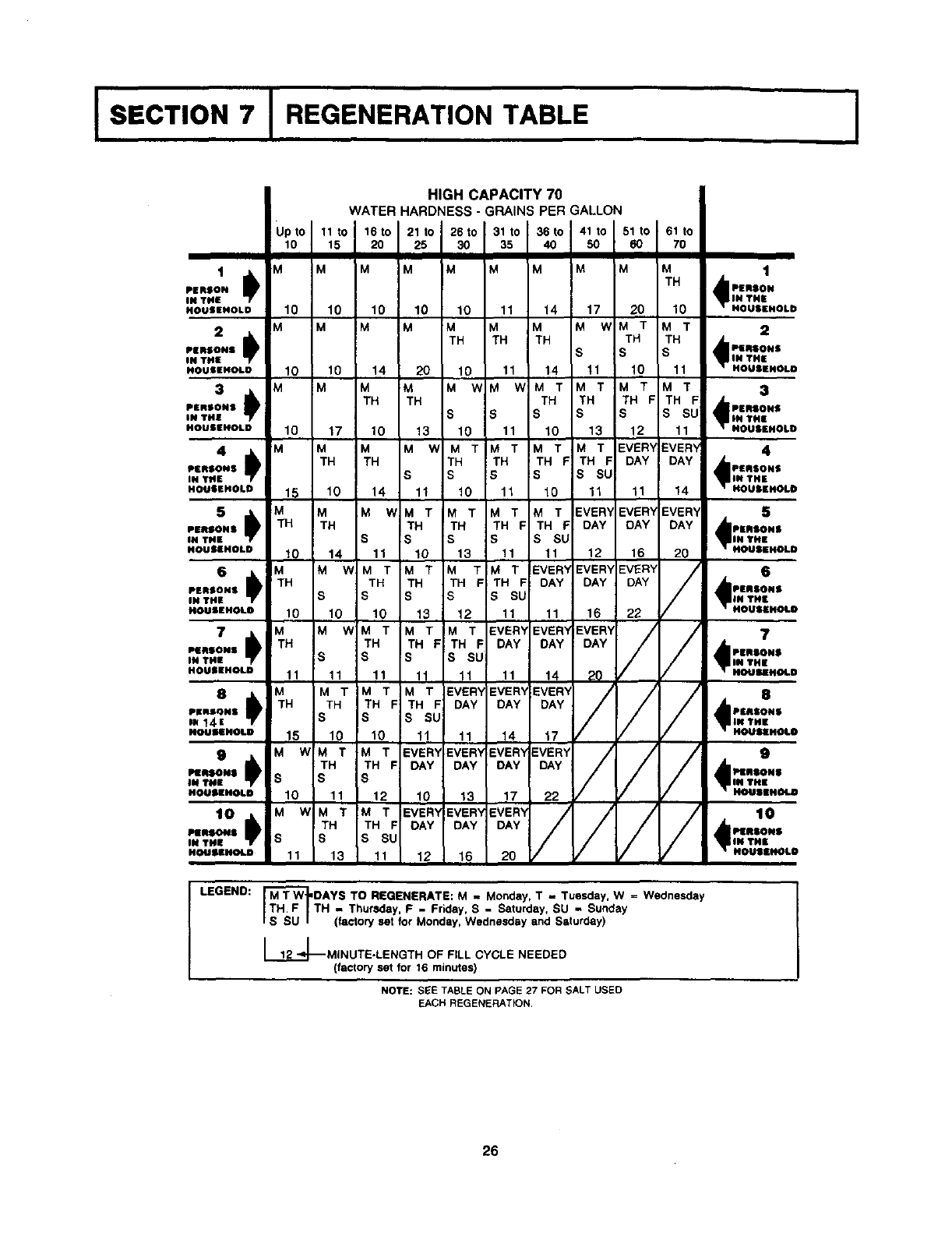
REGENERATION TABLE: The table (page 26)
makes it easy for you to pick the best regeneration
and fill time setting to use.
Step 1-- Go down the side of the table, to the
number of persons in your family, or the number of
people in the house using water.
Step 2 -- Across the top of the table, find the col-
umn listing the grains per gallon hardness of your
water.
Step 3 -- Read across and down the table fo find
the point where steps 1 and 2 meet. At this meeting
point, suggested days to regenerate, and fill cycle
minutes needed are shown.
WRITE IN YOUR RESULTS HERE•
1. M T W TH F SSU Suggested days to
-circle suggested days- regenerate
2. __Fill Cycle minutes needed
TO SET THE TIMER FOR DAYS OF REGENERA-
TION, AND FILL MINUTES, DO THE FOLLOWING.
NOTE: Remember, the timer is factory set for Mon-
day, Wednesday and Saturday regenerations start-
ing at 2:00 A.M. Filltime is factory set for 16 minutes.
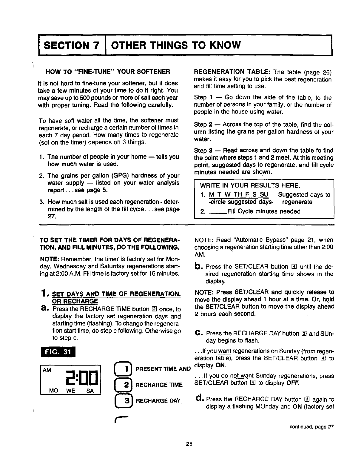
1. srr DAYS AND TIME OF REGENERATION,
OR RECHARGE
a, Press the RECHARGE TiME button [] once, to
display the factory set regeneration days and
starting time (flashing). To change the regenera-
tion start time, do step b following. Otherwise go
to step c.
PRESENT TIME AND
RECHARGE TIME
RECHARGE DAY
r--
NOTE: Read "Automatic Bypass" page 21, when
choosing a regeneration starting time other than 2:00
AM.
b.Press the SET/CLEAR button [] until the de-
sired regeneration starting time shows in the
display.
NOTE: Press SET/CLEAR and quickly release to
move the display ahead 1 hour at a time. Or, hold
the SET/CLEAR button to move the display ahead
2 hours each second.
C. Press the RECHARGE DAY button [] and SUn-
day begins to flash.
...If you want regenerations on Sunday (from regen-
eration table), press the SET/CLEAR button [] to
display ON.
•..If you do not want Sunday regenerations, press
SET/CLEAR button [] to display OFF.
d.Press the RECHARGE DAY button _1 again to
display a flashing MOnday and ON (factory set
continued, page 27
25
I SECTION 7 I REGENERATION TABLE I
HIGH CAPACITY 70
WATERHARDNESS-GRAINSPER GALLON
:N i M MMMM M M M M M , 1TH
PEa a PERION
N TNi[ _IN THE
4OUSEHOLD M10 M10 M10 M10 M10 Mll M14 17 20 M10T NOUIEHOLI:
)s
2 TH TH TH TH 2
,=naONSNT_[ S 11 S 10 IN_insoNeTHE
_OUeKNOLO3 M10 M10 M14 :M20 M10 hM11W M14T M11T HOUIIENOLE
MTMT,....ON.3
TH TH sTH TH TH F TH F:
'[mSONSNTH= S tS11 S 13 $12 S SU! mTM
_OUSEHOLD M 10 M 17 M 10 M13W M'0 10 11 HOUSEHOL]0
4_TH T MHT MHTFM T EVER'EVERY , 4
PERSONS TH TH PeaeoNe
THsF DAY DAY
IHTH[ $1t $11 $10 I#TH=
NOUIEHOLD M15 10 14 10 11 11 14 HOUIEHOL|
50) TH _MH M M, T M T M M,JT11SEVER'I EVER'( EVERY , 5
PER@ONe
HOUSEHOLDINTHE S 1 iN THE
12 16 ,.o.=..o,.=
M 10 1T /EF VER'_ EVER't 6
S"Ib" MW M T M1 IF)A_ DAY :DAY
_nao#a TH MneoHa
iN THE IV S S SU ;N THa
11 16 .OUll.OU
14 11 I0T 13 M11T 11
•M M T EVERY EVERY
sTH TH TH F THIsF DAY
IlOUS[NOLr_8,0) MIO MIOW M`HO M13 MI2T EVER' EV1;Ry EVERY/_/// __"/
M[HIONI TH HTF THsF DAY DAY DAY
s11 s11 _/ *"'=HaO"STH=
IX "*'HIE M 111. 11 20// HOUlMEH_|
NOUIINOL, M11 MTH] M EV1;Ry 14
) EVER_ 8
EVER_
TH HTF; TH F DAY DAY DAY
PI[IISQN$ PaHION$
1"14E M$10 M10T S I_U INTHE
HouaINOLD 15 w N_HOLI
_Na DAY DAY DAY DAy i_ PlEH_H@
114l_l IX THE
HO_iIIEHOLD S10 11 12 10 13 17 HOUIIH_
'I0 M W M TM T EVER'YEVERYEVER, _/, 10
r H TH F DAY DAY DAY
e=nsoHa
IN THE SSS_ IN THE
NOUBIHOLD 11 13 11 12 16 20 HouaaNOL|
LEGEND:
DAYS TO REGENERATE: M - Monday, T - Tuesday, W =Wednesday
TH - Thursday, F - Friday, S - Saturday, SU - Sunday
(factory set for Monday, Wednesday and Saturday)
[_._2_MINUTE-LENGTH OF FILL CYCLE NEEDED
(factory set for 16 minutes)
NOTE: SEE TABLE ON PAGE 27 FOR SALT USED
EACH REGENERATION.
26
I SECTION 7 I OTHER THINGS TO KNOW I
continued from page 25
recharge). As you did in step c, use the SET/
CLEAR button [] to change the display from ON
to OFF, or from OFF to ON.
e. Press RECHARGE DAY button [] to display a
flashing TUesday, WEdnesday, etc., each time
using the SET/CLEAR button [] to display either
ON or OFF as needed.
After recharge is either set or cancelled for
SAturday, press the PRESENT TIME AND DAY
button [] once again to return the present time
and day display.
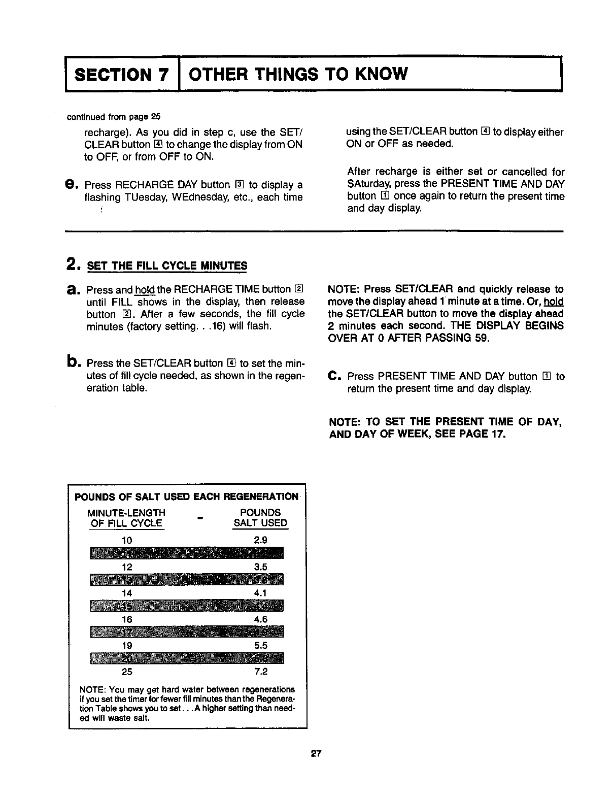
2, SET THE FILL CYCLE MINUTES
a. Press and hold the RECHARGE TIME button []
until FILL shows in the display, then release
button []. After a few seconds, the fill cycle
minutes (factory setting...16) will flash.
b. Press the SET/CLEAR button [] to set the min-
utes of fill cycle needed, as shown in the regen-
eration table.
NOTE: Press SET/CLEAR and quickly release to
move the display ahead I minute at a time. Or, hold
the SET/CLEAR button to move the display ahead
2 minutes each second. THE DISPLAY BEGINS
OVER AT 0 AFTER PASSING 59,
C, Press PRESENT TIME AND DAY button [] to
return the present time and day display.
NOTE: TO SET THE PRESENT TIME OF DAY,
AND DAY OF WEEK, SEE PAGE 17.
POUNDS OF SALT USED EACH REGENERATION
MINUTE-LENGTH
OF FILL CYCLE POUNDS
SALT USED
10 2.9
m .......... I
12 3.5
14 4.1
16 4.6
19 5,5
25 7.2
NOTE: You may get hard water between regenerations
if youset the timerfor fewerfill minutesthanthe Regenera-
tionTable showsyouto set... A highersetting than need-
ed will waste salt,
27
I SECTION 7 I OTHER THINGS TO KNOW I
A
_ C --------
--IEI-
! i !
B
I'F--I
Dia.
Resin Tank
MODEL AND
RATING DECAL
(under cover)
_lnlet-Outlet
i
-r-
_G H
I-
t-
(1)
h-
i
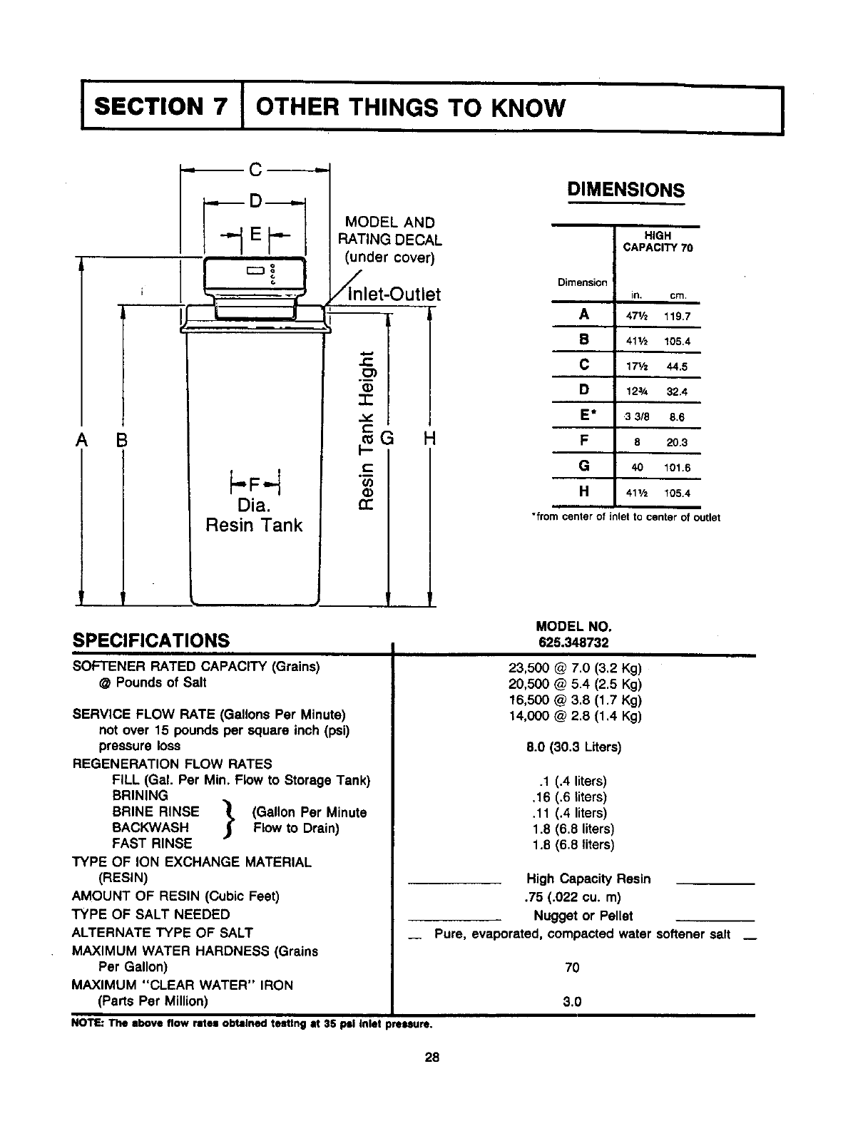
DIMENSIONS
HIGH
CAPACITY 70
Dimension
in. cm.
A471/2 119.7
S 411h 105.4
C 17V= 44.5
D12¾ 32.4
E* 3 3/8 8.6
F 5 20.3
G 40 101.6
H411/= 105.4
*from center of inlet to center of outlet
SPECIFICATIONS MODEL NO.
625.348732
SOFTENER RATED CAPACITY (Grains)
@ Pounds of Salt
SERVICE FLOW RATE (Gallons Per Minute)
not over 15 pounds per square inch (psi)
pressure loss
REGENERATION FLOW RATES
FILL (Gal. Per Min. Flow to Storage Tank)
BRINING
BRINE RINSE _. (Gallon Per Minute
BACKWASH J_ Flow to Drain)
FAST RINSE
TYPE OF ION EXCHANGE MATERIAL
(RESIN)
AMOUNT OF RESIN (Cubic Feet)
TYPE OF SALT NEEDED
ALTERNATE TYPE OF SALT
MAXIMUM WATER HARDNESS (Grains
Per Gallon)
MAXIMUM "CLEAR WATER" IRON
(Parts Per Million)
23,500 @ 7.0 (3.2 Kg)
20,500 @ 5.4 (2.5 Kg)
16,500 @ 3.8 (1.7 Kg)
14,000 @ 2.8 (1.4 Kg)
8.0 (30.3 Liters)
.1 (,4 liters)
.16 (.6 liters)
.11 (.4 liters)
1.8 (6.8 liters)
1.8 (6.8 liters)
High Capacity Resin
.75 (.022 cu. m)
Nugget or Pellet
_Pure, evaporated, compacted water softener salt _
70
3.0
NOTE: The above flow rates obtained testing at 35 psi inlet pressure.
28
I SECTION 7 I OTHER THINGS
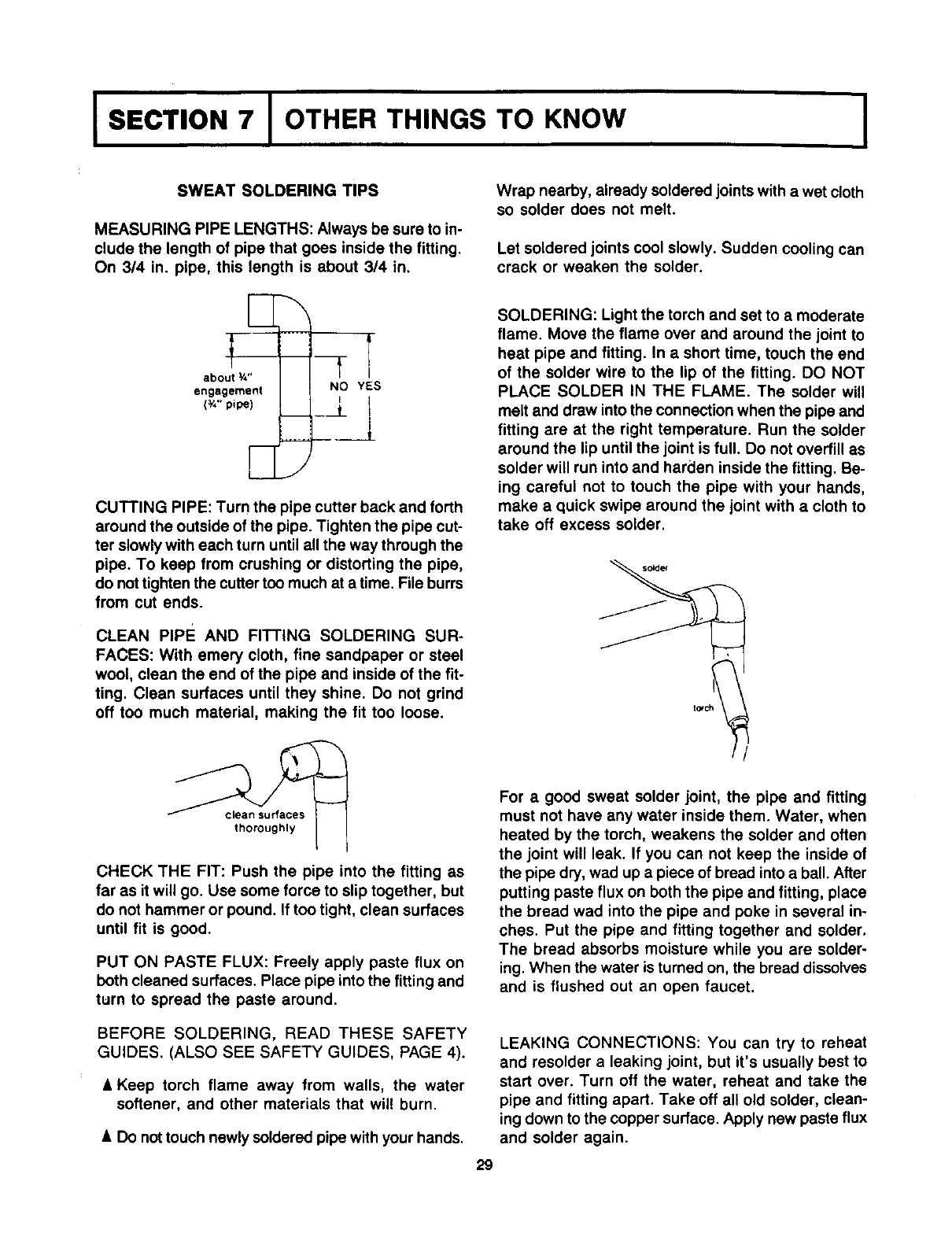
SWEAT SOLDERING TIPS
MEASURING PIPE LENGTHS: Always be sure to in-
clude the length of pipe that goes inside the fitting.
On 3/4 in. pipe, this length is about 314 in,
TO KNOW I
Wrap nearby, already soldered joints with a wet cloth
so solder does not melt.
Let soldered joints cool slowly. Sudden cooling can
crack or weaken the solder.
CUTTING PIPE: Turn the pipe cutter back and forth
around the outside of the pipe. Tighten the pipe cut-
ter slowly with each turn until all the way through the
pipe. To keep from crushing or distorting the pipe,
do not tighten the cutter too much at a time. File burrs
from cut ends.
CLEAN PIPE AND FITTING SOLDERING SUR-
FACES: With emery cloth, fine sandpaper or steel
wool, clean the end of the pipe and inside of the fit-
ting. Clean surfaces until they shine. Do not grind
off too much material, making the fit too loose.
SOLDERING: Light the torch and set to amoderate
flame. Move the flame over and around the joint to
heat pipe and fitting. In ashort time, touch the end
of the solder wire to the lip of the fitting. DO NOT
PLACE SOLDER IN THE FLAME. The solder will
melt and draw into the connection when the pipe and
fitting are at the right temperature. Run the solder
around the lip until the joint is full. Do not overfill as
solder will run into and harden inside the fitting. Be-
ing careful not to touch the pipe with your hands,
make a quick swipe around the joint with a cloth to
take off excess solder.
solder
//
clean surfaces
thoroughly
CHECK THE FIT: Push the pipe into the fitting as
far as it will go. Use some force to slip together, but
do not hammer or pound. If too tight, clean surfaces
until fit is good.
PUT ON PASTE FLUX: Freely apply paste flux on
both cleaned surfaces. Place pipe into the fitting and
turn to spread the paste around.
BEFORE SOLDERING, READ THESE SAFETY
GUIDES. (ALSO SEE SAFETY GUIDES, PAGE 4).
&Keep torch flame away from walls, the water
softener, and other materials that wil! burn.
•Do not touch newly soldered pipe with your hands.
For a good sweat solder joint, the pipe and fitting
must not have any water inside them. Water, when
heated by the torch, weakens the solder and often
the joint will leak. If you can not keep the inside of
the pipe dry, wad up a piece of bread into a ball. After
putting paste flux on both the pipe and fitting, place
the bread wad into the pipe and poke in several in-
ches. Put the pipe and fitting together and solder.
The bread absorbs moisture while you are solder-
ing. When the water is turned on, the bread dissolves
and is flushed out an open faucet.
29
LEAKING CONNECTIONS: You can try to reheat
and resolder aleaking joint, but it's usually best to
start over. Turn off the water, reheat and take the
pipe and fitting apart. Take off all old solder, clean-
ing down to the copper surface. Apply new paste flux
and solder again.
ISECTION 7 I OTHER THINGS TO KNOW I
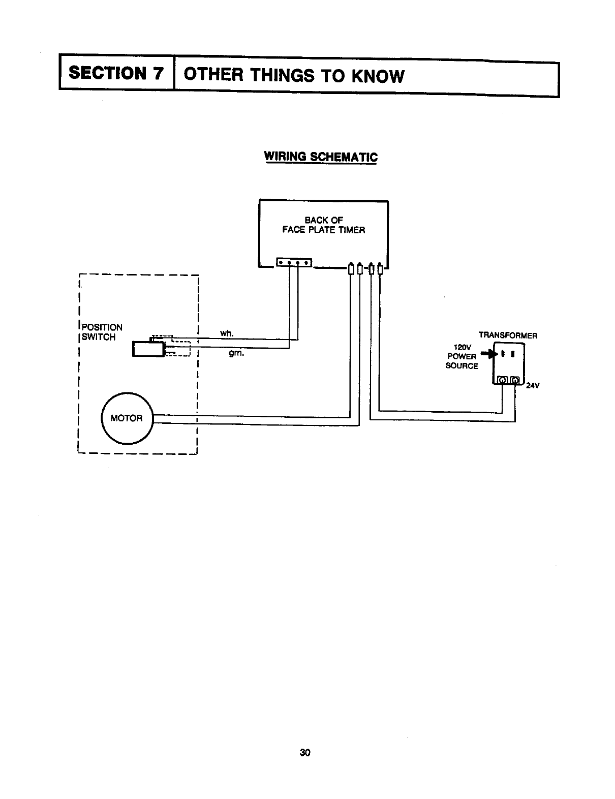
WIRING SCHEMATIC
f
I.
I
I
IPOSITION
_w,_o__::_, wh.
grn.
lBACK OF
A_E__LATE TIMER1"1
TRANSFORMER
12ov J-_l
POWER _I I
SOURCE |
_24V
3O

I I
31
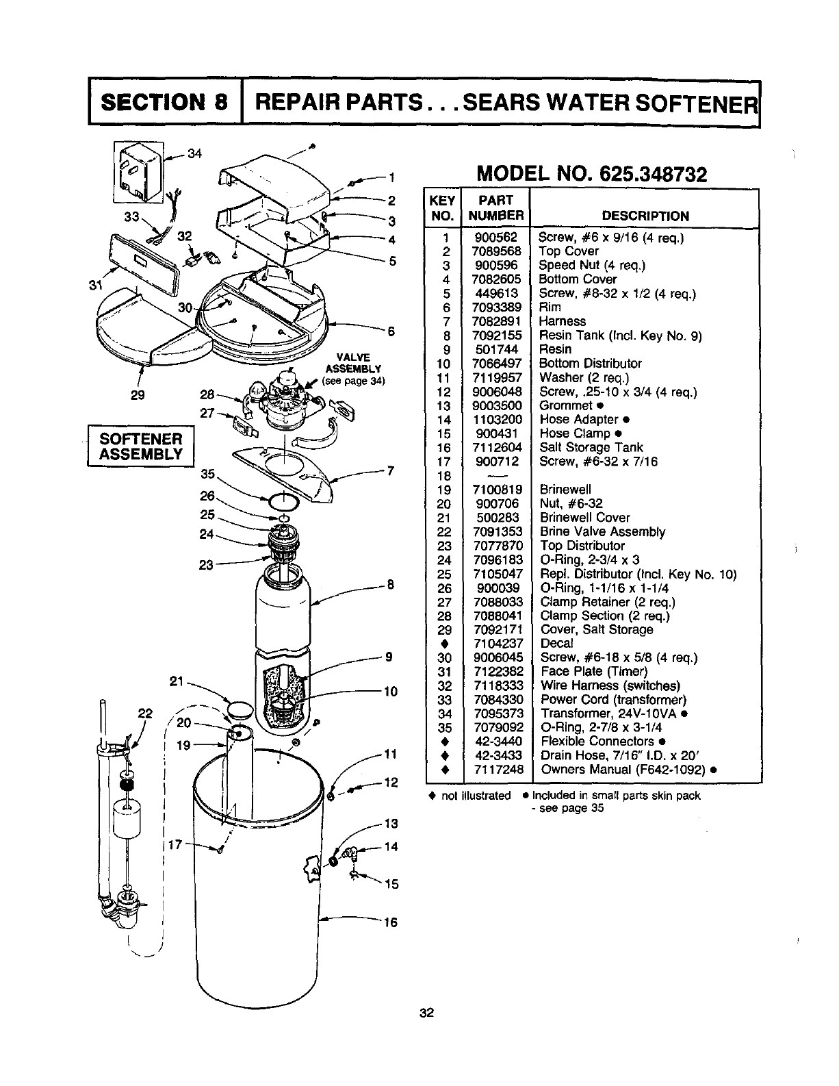
Is c,,oN8I,EP.,,P..TS..SE.,SW.TE.SOFTE,E,r
fSO EN'°JASSEMBLY
23
10
/
16
MODEL NO. 625.348732
KEY PART
NO. NUMBER DESCRIPTION
1 900562
2 7089568
3 900596
47082605
449613
7093389
7 7082891
8 7092155
9 501744
10 7066497
11 7119957
12 9006048
13 9003500
14 1103200
15 900431
16 7112604
17 900712
18
19 7100819
20 900706
21 500283
22 7091353
23 7077870
24 7096183
25 7105047
26 900039
27 7088033
28 7088041
29 7092171
• 7104237
30 9006045
31 7122382
32 7118333
33 7084330
34 7095373
35 7079092
•42-3440
• 42-3433
•7117248
•not
Screw, #6 x9/16 (4 req.)
Top Cover
Speed Nut (4 req.)
Bottom Cover
Screw, #8-32 x 1/2 (4 req.)
Rim
Harness
Resin Tank (Incl. Key No. 9)
Resin
BottomDistributor
Washer (2 req.)
Screw, .25-10 x 3/4 (4 req.)
Grommet •
Hose Adapter •
Hose Clamp •
Salt Storage Tank
Screw, #6-32 x 7/16
Brinewell
Nut, #6-32
Brinewell Cover
Brine Valve Assembly
Top Distributor
O-Ring, 2-3/4 x 3
RepL Distributor(Incl. Key No. 10)
O-Ring, 1-1/16 x 1-1/4
Clamp Retainer (2 req.)
Clamp Section (2 req.)
Cover, Salt Storage
Decal
Screw, #6-18 x 5/8 (4 req.)
Face Plate (Timer)
Wire Harness (switches)
Power Cord (transformer)
Transformer, 24V-10VA •
O-Ring, 2-7/8 x 3-1/4
Flexible Connectors •
Drain Hose, 7/16" I.D. x 20'
Owners Manual (F642-1092) •
illustrated • Includedin small parts skin pack
-see page 35
32
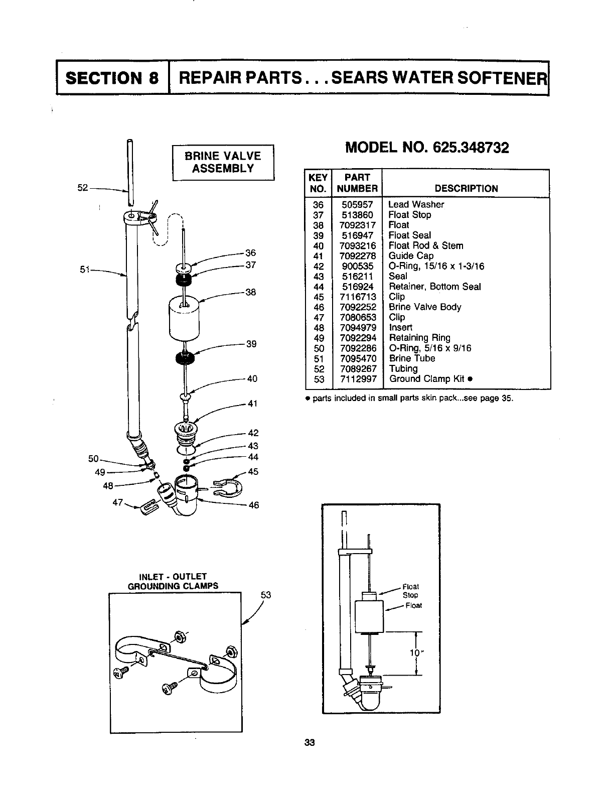
BRINE VALVE
ASSEMBLY
MODEL NO. 625.348732
KEY PART
NO. NUMBER DESCRIPTION
36
37
38
39
40
41
42
43
44
45
46
47
48
49
50
51
52
53
505957
513860
7092317
516947
7093216
7092278
900535
516211
516924
7116713
7092252
7080653
7094979
7092294
7092286
7095470
7089267
7112997
Lead Washer
Float Stop
Float
Float Seal
Float Rod & Stem
Guide Cap
O-Ring, 15/16 x 1-3/16
Seal
Retainer, Bottom Seal
Clip
Brine Valve Body
Clip
Insert
RetainingRing
O-Ring, 5/16 x 9/16
BrineTube
Tubing
Ground Clamp Kit •
• parts included in small parts skEnpack..+see page 35.
49
INLET -OUTLET
GROUNDING CLAMPS
46
53
/
N
1i
33
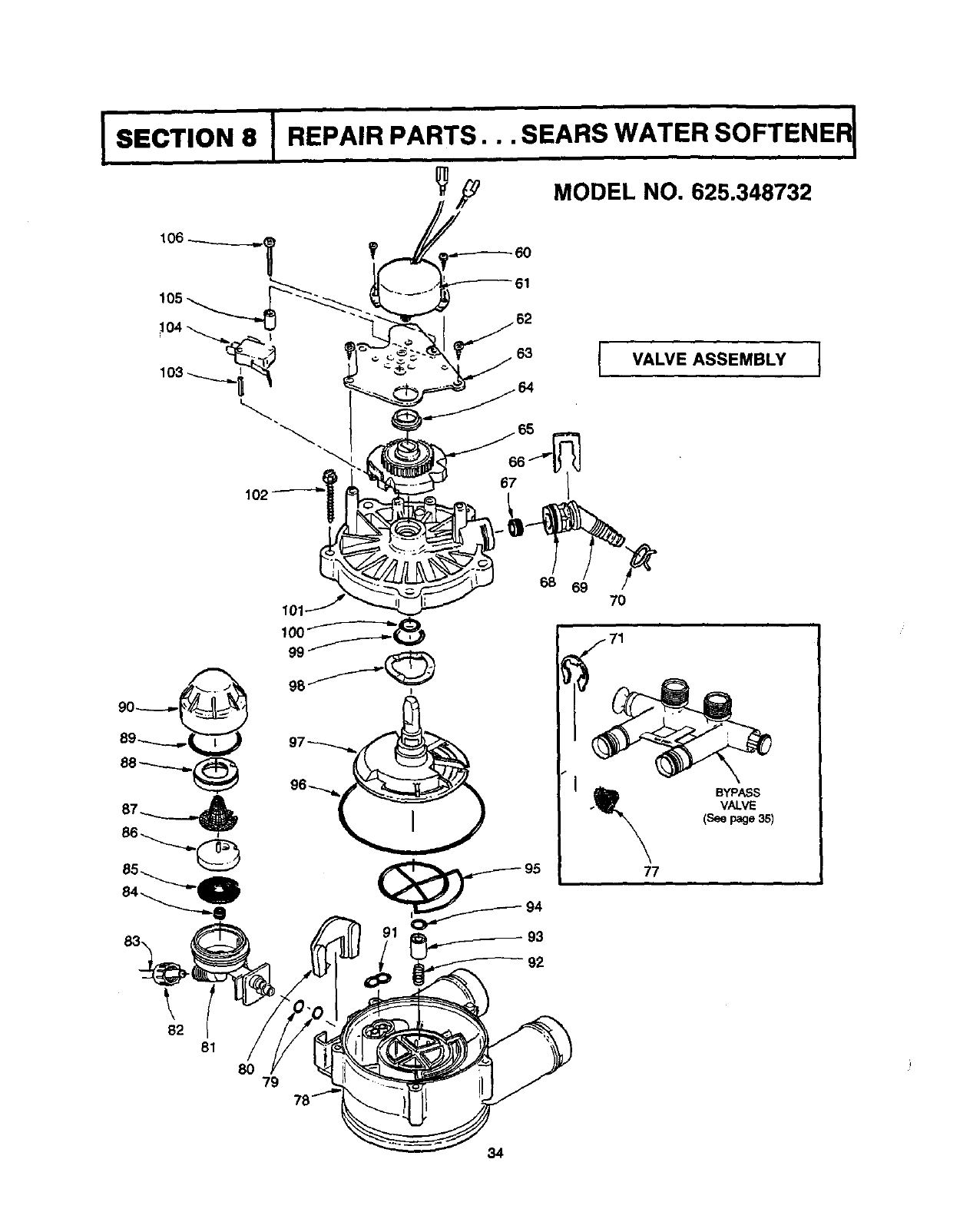
ISECTION 8 I"REPAIR PARTS... SEARS WATER SOFTENER
,_ MODEL NO. 625.348732
50
61
63 VALVE ASSEMBLY J
89
82 81
80 79
68 69 7O
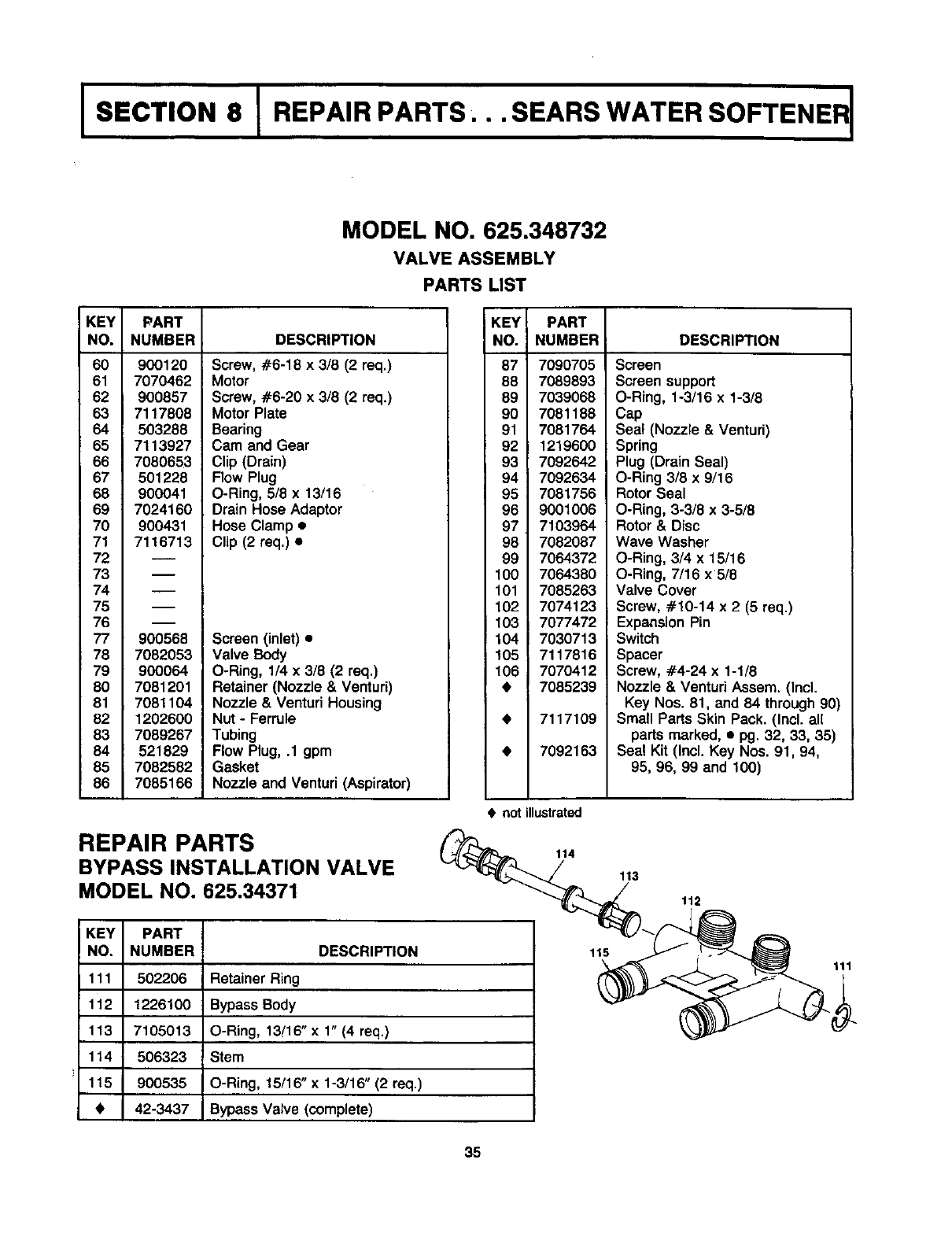
MODEL NO. 625.348732
VALVE ASSEMBLY
PARTS LIST
KEY PART
NO. NUMBER DESCRIPTION
60
61
62
63
64
65
66
67
68
69
70
71
72
73
74
75
76
77
78
79
8O
81
82
83
84
85
86
900120
7070462
900857
7117808
503288
7113927
7080653
501228
900041
7024160
900431
7116713
m
900568
7082053
900064
7081201
7081104
1202600
7089267
521829
7082582
7085166
Screw, #6-18 x3/8 (2 req.)
Motor
Screw, #6-20 x 3/8 (2 req.)
Motor Plate
Bearing
Cam and Gear
Clip (Drain)
Flow Plug
O-Ring, 5/8 x 13/16
Drain Hose Adaptor
Hose Clamp •
Clip (2 req.) •
Screen (inlet) •
Valve Body
O-Ring, 1/4 x 3/8 (2 req.)
Retainer (Nozzle & Ventud)
Nozzle & Ventud Housing
Nut - Ferrule
Tubing
Flow Plug, .1 gpm
Gasket
Nozzle and Venturi(Aspirator)
REPAIR PARTS
BYPASS INSTALLATION VALVE
MODEL NO. 625.34371
KEY
NO.
111
112
113
114
115
PART
NUMBER
502206
1226100
7105013
506323
900535
42-3437
DESCRIPTION
Retainer Ring
Bypass Body
O-Ring, 13/16" x 1" (4 req.)
Stern
O-Ring, 15/16" x 1-3/16" (2 req.)
Bypass Valve (complete)
KEY I
NO. i
87' 7090705
88 7089893
89 7039068
90 7081188
91 7081764
92 1219600
93 7092642
94 7092634
95 7081756
96 9001006
97 7103964
98 7082087
99 7064372
100 7064380
101 7085263
102 7074123
103 7077472
104 7030713
105 7117816
106 7070412
•7085239
PART
NUMBER DESCRIPTION
7117109
7092163
Screen
Screen support
O-Ring, 1-3/16 x 1-3/8
Cap
Sea! (Nozzle & Venturi)
Spring
Plug (Drain Seal)
O-Ring 3/8 x 9/16
RotorSeal
O-Ring, 3-3/8 x 3-5/8
Rotor & Disc
Wave Washer
O-Ring, 3/4 x 15/16
O-Ring, 7/16 x5/8
Valve Cover
Screw, #10-14 x 2 (5 req.)
ExpansionPin
Switch
Spacer
Screw, -#4-24 x 1-1/8
Nozzle & VenturiAssem. (Incl.
Key Nos. 81, and 84 through90)
Small Parts Skin Pack. (Incl. all
partsmarked, •pg. 32, 33, 35)
Sea! Kit (Incl. Key Nos. 91, 94,
95, 96, 99 and 100)
• not illustrated
114
113
112
115 111
35
E_ARS
OWNERS
MANUAL
SERVICE
MODEL NO.
625.348732
HOW TO ORDER
REPAIR PARTS
TELL SEARS YOU
WANT IT INSTALLED
THEN RELAX
F642-1092
Kenmore
High Capacity 70
Now that you have purchased your water softener, should a need ever
exist for repair parts or service, simply contact any Sears Service Center.
Be sure to provide all pertinent facts when you call or visit.
The model number of your water softener is found on the rating decal.
This decal is on the storage tank rim, under the cover plate.
WHEN ORDERING REPAIR PARTS, ALWAYS GIVE THE FOLLOW-
ING INFORMATION:
-- PART NUMBER
-- MODEL NUMBER
-- PART DESCRIPTION
-- NAME OF ITEM
All parts listed may be ordered from any Sears Service Center.
If the parts you need are not stocked locally, your order will be elec-
tronically transmitted to a Sears Repair Parts Distribution center for
handling.
When Sears arranges the installation, you can be sure the job is done
right. We will arrange for professional workmanship.., and we'll take
care of the entire project. What's more, during installation you get in-
sured protection.., against property damage and also against accidents
to workmen. All you have to do is talk to your Sears salesperson or
call your nearest Sears store today for detailed information.
Sears, Roebuck and Co., Chicago, III. 60684 U.S.A.
7117248 (3/92)
