Kenmore 625348832 User Manual WATER SOFTENER Manuals And Guides L0811057
KENMORE Water softener Manual L0811057 KENMORE Water softener Owner's Manual, KENMORE Water softener installation guides
User Manual: Kenmore 625348832 625348832 KENMORE WATER SOFTENER - Manuals and Guides View the owners manual for your KENMORE WATER SOFTENER #625348832. Home:Plumbing Parts:Kenmore Parts:Kenmore WATER SOFTENER Manual
Open the PDF directly: View PDF ![]() .
.
Page Count: 32
OWNERS
ANUAL
MODEL NO.
625.348832
CAUTION
Read All Safety
Guides Before
You Start to
Install Your
Softener
AVOID UNNEEDED
SERVICE CALLS...
Read the HELPFUL HINTS
CHECKLIST on page 24.
The programming guides on
the underside of the Salt
Storage Tank Cover are also
helpful.
SAVE THIS MANUAL
PRINTED IN USA.
Kenmor'e
@apa¢ ty Phas
HOW TO INSTALL --
HOW IT WORKS
CARE OF
SPECI FICATIONS
REPAIR PARTS
i i ,i_, i,-i H,i
Sears, Roebuck and Co., Chicago, II1_60684 U.S.A.
.... ii ii i ....
i .... I
SEARS RESIDENTIAL WATER SOFTENER
-.................... ..... ill ill i ......................: uJi ..... Hl l
FULL ONE YEAR WARRANTY ON WATER SOFTENER
For' one year from the date of purchase, when this water softener' is installed and maintained
in accordance with our instructions, Sears will repair, free of charge, defects in material
or' workmanship in this water softener..
FULL TEN YEAR WARRANTY AGAINST LEAKS
For ten years from the date of purchase, Sears will furnish and install a new.current model
water softener tank or salt storage drum, free of charge, if either the tank or drum develop
a leak ..................................
TO OBTAIN WARRANTY SERVICE, SIMPLY CONTAOT-THE NEAREST SEARS SERVICE
CENTER THROUGHOUT THE UNITED STATES This warranty applies on'ly while this pro-
duct is in use in the United States. _......... ;/_ ._ .
This warranty gives you specific legal rights, and you may h_ve 0ther _rights wh ch vary from
state to state..
Sears, Roebuck and Co. Dept. 731-CR-W, Sears Tower, Chicago, tL 60684
If you want your water softener professionally installed, talk to your Sears Salesman. He will arrange for
a prompt, quality installation by Sears Authorized Installers..
SEARS INSTALLATION POLICY
All installation labor arranged by Sears shall be per-
formed in a neat, workmanlike manner in accordance
with generally accepted trade practices_ Further', all
installations shall comply with all local laws, codes,
regulations and ordinances_ Customer shall also be
protected, during installation, by insurance relating
to Property Damage, Workman's Compensation and
Public Liability.
SEARS INSTALLATION WARRANTY
In addition to any warranty extended to you on the
Sears merchandise involved, which warranty
becomes effective the date the merchandise is in-
stalled, should the workmanship of any Sears
arranged installation prove faulty within one year,
Sears will, upon notice from you, cause such faults
to be corrected at no additional cost to you_
2
....................oF........................
ITABLE CONTENTS
SECTION 1
SECTION 3
SECTION 5
SECTION 7
PAGE
NO.
Unpacking The Softener ................................................................. 4
Safety Guides ................................................................ 4
Before You Start To install Your Softener ....................................... 5-9
Water System Tests .............................................................. 5
Where To Install The Softener .......................................... 6
Plan How You Will Install The Softener ....................................... 7-8
Tools, Pipe, Fittings and Other Materials Needed ....................... 7
Step By Step Guides To Install Your Softener ............................... 9-'14
Install Sears Plastic Bypass Valve ............................................ 9
Connect In and Out Pipes To Softener .................................... 10
Fasten Drain Hoses To Softener ......................................... !1-12
Check Your Plumbing Work For Leaks .................................... 12
Connect Softener To Electrical Power ................................. 13
Check List of Step By Step Installing Guides ............................. 14
Softener Start-Up .................................................................... t 5-17
Sanitizing The Water Softener ................................................ 15
Make The Face Plate Timer Settings ..................................... 15-16
Filling The Salt Storage Tank With Salt .................................. 17
How Your Water Softener Works ............................................ 18-21
Face Plate Timer Features .................................................... 18
Service- Regeneration -Automatic Bypass - Electronics ............... 21
Wiring Connection Diagram ..................................................... 21
Care of Your Softener ........................................................ 22-25
Checking The Salt Storage Level and Refilling ......................... 22
Breaking a Salt Bridge ........................................................ 22
Cleaning The Outer Covers ................................................. 23
Cleaning The Nozzle and Venturi .......................................... 23
Cleaning iron From The Resin Bed .................................... 23
Protect Softener From Freezing .......................................... 24
Check List Before You Call Fbr Service ................................... 24-25
Other Things To Know .......................................................... 26-27
Sweat Soldering Tips .................................................. 26
Dimensions and Specifications ............................................ 27
Repair Parts ................................................................. 28-3t
How To Order Repair Parts ........................................... Back Cover
3
iS_CTiON ...................... ::.:l:Jwll:,l J i ,IIU NPACK! NG_"r! i iillll it, ii Ill, Ill SAFETYII I,I I,II IIl lll G U_DES
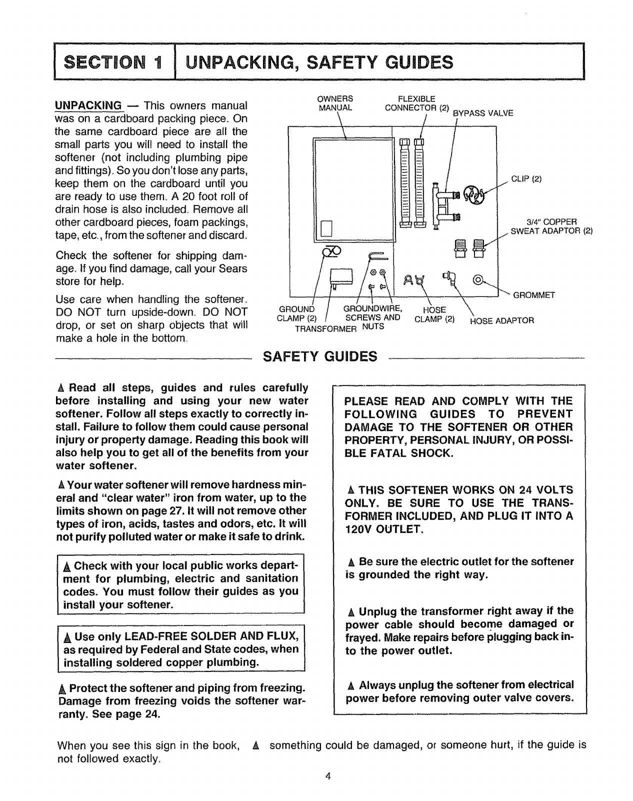
UNPACKING -- This owners manual
was on a cardboard packing piece. On
the same cardboard piece are all the
small parts you will need to install the
softener (not including plumbing pipe
and fittings).. So you don't lose any parts,
keep them on the cardboard until you
are ready to use them° A 20 foot rol! of
drain hose is also included. Remove all
other cardboard pieces, foam packings,
tape, etc°, from the softener and discard.,
Check the softener for shipping darn-
age., If you find damage, call your Sears
store for help.
Use care when handling the softeneL
DO NOT turn upside-down. DO NOT
drop, or set on sharp objects that will
make a hole in the bottom
GROUND
CLAMP (2)
OWNERS
MANUAL
\
D
FLEXIBLE
CONNECTOR (2) BYPASS VALVE
/ /
\
SCREWS AND
TRANSFORMER NUTS
CLIP (2)
3/4" COPPER
SWEAT ADAPTOR (2)
1-"
"'" GROMMET
CLAMP (2) HOSE ADAPTOR
SAFETY GUIDES
ARead all steps, guides and rules carefully
before installing and using your new water
softener. Follow all steps exactly to correctly in-
stall. Failure to follow them could cause personal
injury or property damage. Reading this book will
also help you to get all of the benefits from your
water softener.
h, Your water softener will remove hardness min-
eral and "clear water" iron from water, up to the
limits shown on page 27. It will not remove other
types of iron, acids, tastes and odors, etc. It will
not purify polluted water or make it safe to drink.
Ak Check with your local public works depart-
ment for plumbing, electric and sanitation
codes. You must follow their guides as you
install your softener.
AUse only LEAD-FREE SOLDER AND FLUX,
as required by Federal and State codes, when
installing soldered copper plumbing.
A Protect the softener and piping from freezing.
Damage from freezing voids the softener war-
ranty. See page 24.
PLEASE READ AND COMPLY WITH THE
FOLLOWING GUIDES TO PREVENT
DAMAGE TO THE SOFTENER OR OTHER
PROPERTY, PERSONAL INJURY, OR POSSI-
BLE FATAL SHOCK.
A THIS SOFTENER WORKS ON 24 VOLTS
ONLY. BE SURE TO USE THE TRANS-
FORMER INCLUDED, AND PLUG IT INTO A
120V OUTLET.
ABe sure the electric outlet for the softener
is grounded the right way.
AUnplug the transformer right away if the
power cable should become damaged or
frayed. Make repairs before plugging back in-
to the power outlet.
h, Always unplug the softener from electrical
power before removing outer valve covers.
When you see this sign in the book,
not followed exactly..
A something could be damaged, or someone hurt, if the guide is
4
HELPFUL INFORMATION
If you know little about plumbing skills, we sug-
gest you get a book on the subject,. There are
many good books for do-it-yourselfers on the
basics of plumbing_ You can get a low cost book
from Sears Plumbing and Heating departments
that will help you. Some basic sweat soldering
tips are on page 26 of this manual_
WATER SYSTEM TESTS
HAS YOUR WATER SUPPLY HAD A CHEMICAL
ANALYSIS? Sears has many kinds of water
treating units (see page 6) to correct different
water problems. To know the kind and size of unit
you need, you must first know what elements are
in your house water supply_ A chemical analysis
shows the type and amounts of elements in water.
If your water needs analysis, call or write your
nearest Sears store for hetp_
CHECK YOUR WATER PRESSURE -- For your
softener to work right, a water pressure of no lower
than 20 pounds per square inch (psi) is needed
in the house water pipes_ The highest pressure
A allowed in the water pipes is 120 psi° If pressure
is over 120 psi, buy and install a pressure reduc-
ing valve in the water inlet pipe to the softener_
NOTES: If water pressure during the day is 100 psi
or more, pressure during the night may go over
120 psi ..... Adding a pressure reducing valve may
reduce the flown
If you have a well water system, look at the
pressure gauge to find the water pressure.. Call
your local water department if you have city water.
In
24
r
4_
5_
They will tell you what the water pressure is where
you live..
CHECK YOUR WATER FLOW RATE -- A water
flow of at least 3 gallons per minute is needed.,
A lower flow will keep your softener from working
as well as it should. To make an easy check of
your flow rate, do the following. You wi!l need a
1 gallon container (can, jar, pail, etc.),
Fully open 2 cold water faucets close to the point
water enters the house_
With both faucets open, fill the gallon container
at 1 faucet while looking at a watch or clock to
see how many seconds it takes.
Empty the container and go to the second faucet
(be sure BOTH faucets are still on)o Fill the gallon
container at the second faucet and see how many
seconds it takes.
Turn off both faucets_ Now add the number of
seconds it took to fill the container at both faucets.
A total of 90 seconds, or less, means the system
flow rate is good_
FACTS AND
Fill in the blanks below and keep this book
Water Softener Model Noo
Serial Number
Date Installed
Water Hardness Grains Per Gallon
FIGURES TO KEEP
in a safe place so you always have these facts.
Iron Content Parts Per Million
*_pH Taste And/Or Odor
Water Pressure Pounds/Square inch
Water Flow Rate Gallons Per Minute
SODIUM INFORMATION: Water softeners using
sodium chloride for regeneration add sodium to the
water. Persons who are on sodium restricted diets
should consider the added sodium as part of their
overall sodium intake°
For example, if your water supply is 15 grains hard,
you would have to drink 3 quarts of softened water5
to consume 335 milligrams of sodium. That is
equivalent to eating 2V2 slices of white bread_
Persons who are concerned about their drinking
water should consider a Sears Drinking Water
System that will remove or reduce in excess of 90%
of the sodium and other drinking water contaminants.
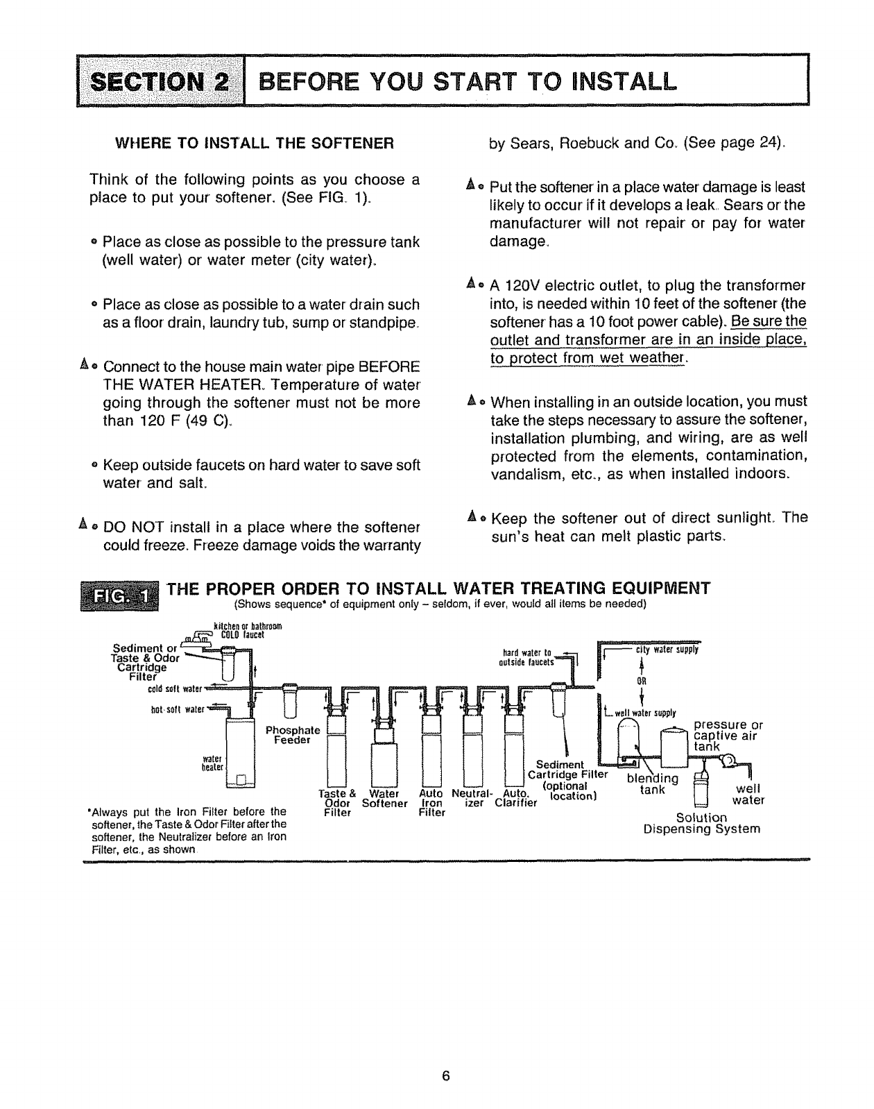
WiiERE TO INSTALL THE SOFTENER
Think of the following points as you choose a
place to put your softener. (See FIG 1).
o Place as close as possible to the pressure tank
(well water) or water meter (city water).
o Place as close as possible to a water drain such
as a floor' drain, laundry tub, surnp or standpipe°
A • Connect to the house main water pipe BEFORE
THE WATER HEATER_ Temperature of water
going through the softener must not be more
than 120 F (49 C)..
o Keep outside faucets on hard water to save soft
water and salt..
,t • DO NOT install in a place where the softener
could freeze. Freeze damage voids the warranty
AO
i_ll It
by Sears, Roebuck and Co. (See page 24).
Put the softener' in a place water damage is least
likely to occur if it develops a leak,, Sears or the
manufacturer will not repair or pay for water
damage.
A 120V electric outlet, to plug the transformer
into, is needed within 10 feet of the softener (the
softener has a 10 foot power cable)° Be sure the
outlet and transformer are in an inside place,
to protect from wet weather.
When installing in an outside location, you must
take the steps necessary to assure the softener,
installation plumbing, and wiring, are as well
protected from the elements, contamination,
vandalism, etc., as when installed indoors.
Keep the softener out of direct sunlighL The
sun's heat can melt plastic parts_
THE PROPER ORDER TO INSTALL WATER TREATING EQUIPMENT
(Shows sequence" of equipment only -seldom, if ever, would all items be needed)
_itchenorbathrootn
Sediment or
Taste & Odor_
Cartridge J {
Filter L+J
coldsortwater'_
hOLmsoft water
watert
heater___
Phosphate
Feeder
"Always put the iron Filter before the
softener, the Taste & Odor Filter after the
softener, the Neutralizer before an Iron
Filter, etc., as shown
Taste &Water
Odor Softener
Filter
hardwater to Jvr'_ city watersupply
eotside _0_
_L well w_ter_ttliptlt
J _ _ pressure or
i ! I _ cap,live air
Sediment _ \. _ ]
Cartridge Filter bler:;'dinQ ,_ q
Neotra,-A to, I=1 we,
Iron izer Clarifier _ water
Filter Solution
Dispensing System
PLAN HOW TO INSTALL YOUR SOFTENER
You must first decide how to run in and out pipes to
the flexible connectors* included with your softener.
Look at your house main water pipe at the point you
wilt connect the softener, ts the pipe soldered copper,
glued plastic, or threaded galvanized or brass? What
is the pipe size? What kind of pipe and fittings is it
easiest for you to work with, and what tools do you
have?
Now look at FIG. 2 on page 8 and use it as a guide to
plan what materials you will need. As you plan your in
and out piping, keep in mind the following check list.
Then get all the materials you will need before you
start°
TOOLS, PIPE, FITTINGS AND
OTHER MATERIALS YOU WILL NEED
_' In and out pipes to the softener must be at least
3/4 in. size° Some local codes may tell you to use
no less than 1 in. pipe size (See Note on page 8).
Use copper, brass, or galvanized pipe and fittings°
Some codes may also allow CPVC plastic pipe°
_" Copper and galvanized pipe corrode fast when
connected together. Use pipe and fittings of the
same material.
_' You can buy adaptors to go from a copper or
threaded to CPVC.
ALWAYS install the bypass valve, which allows
you to turn off water to the softener, but still have
water in the house pipes
Drain hose (7/16 in. inside diameter) is needed for
valve and salt tank drains. Twenty feet of hose is
included. If more hose is needed, you can buy it at
most Sears stores._
If a rigid valve drain is needed to comply with
plumbing codes, you can buy the parts needed
(See page 11) to change the softener to a 1/2 in,.
copper tubing drain.
TOOLS NEEDED:- Common and cross point
(Phillips) screw drivers, slip-joint pliers and a tape
measure or ruleo ALSO ....
o o _for SOLDERED COPPER - tubing cutter,
propane torch, solid-core LEAD-FREE solder,
paste flux, emery cloth, sandpaper or steel wool.
.... for TH READED P1PE- hacksaw or pipe cutter,
pipe wrenches, pipe threading tool, pipe joint
compound approved for use on potable water.
.... for CPVC PLASTIC- hacksaw, adjustable
wrench, solvent cement approved for use on
potable water, primer.
*Flexible connectors are not allowed in some localities. Check your local plumbing codes.
7
i'll'llnll i I iilU illUl ill ........................................ :!l ii I'll .... :: .............
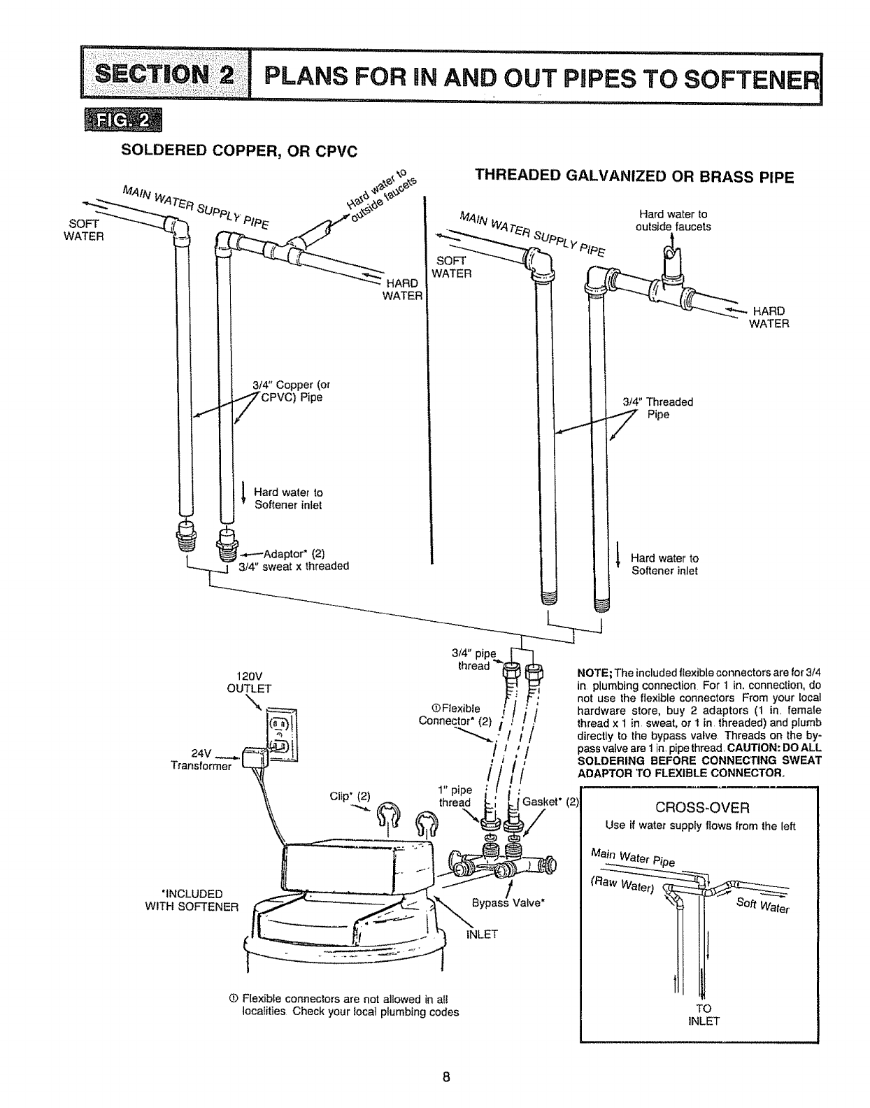
PLANS FOR IN AND_OUT PIPES TO SOFTENER !
................ Inl'll ....... ..... . ..............................
SOFT
WATER
SOLDERED COPPER, OR CPVC
i 3/4" Copper (or
[?,o vo) ,0o
/ l .ardwate,to
L " Softener inlet
)
i..,.-_Adaptor* (2)
3/4" sweat x threaded
THREADED GALVANIZED OR BRASS PIPE
SOFT
WATER
3/4" Threaded
Pipe
I Hard water to
Softener inlet
120V
OUTLET
24V ...._.1
Transformer
3/4" pipe
thread
• Ftexible
Connector"
1" pipe
thread
i!
;/
'i' /
!,
/ _I
*INCLUDED
WITH SOFTENER Bypass/Valve"
|NLET
(b Flexibte connectors are not a_lowed in at_
localities Check your locat plumbing codes
NOTE; The included ltexible connectors are for 3/4
in plumbing connection For 1 in. connection, do
not use the flexible connectors From your local
hardware store, buy 2 adaptors (I in_ female
thread x 1 in sweat, or 1 in threaded) and plumb
directly to the bypass valve Threads on the by-
pass valve are 1 in. pipe thread CAUTION: DO ALL
SOLDERING BEFORE CONNECTING SWEAT
ADAPTOR TO FLEXIBLE CONNECTOR.
(2; CROSS-OVER
Use if water supply flows from the left
Soft Water.
TO
INLET
8
==oT,o.=IsT=PBY....................................... UJl UllUUUUlUUUUU
STEP GUIDES TO iNSTALL ......I
, ,,,,,,,,,,,,,,,u lul luu,t
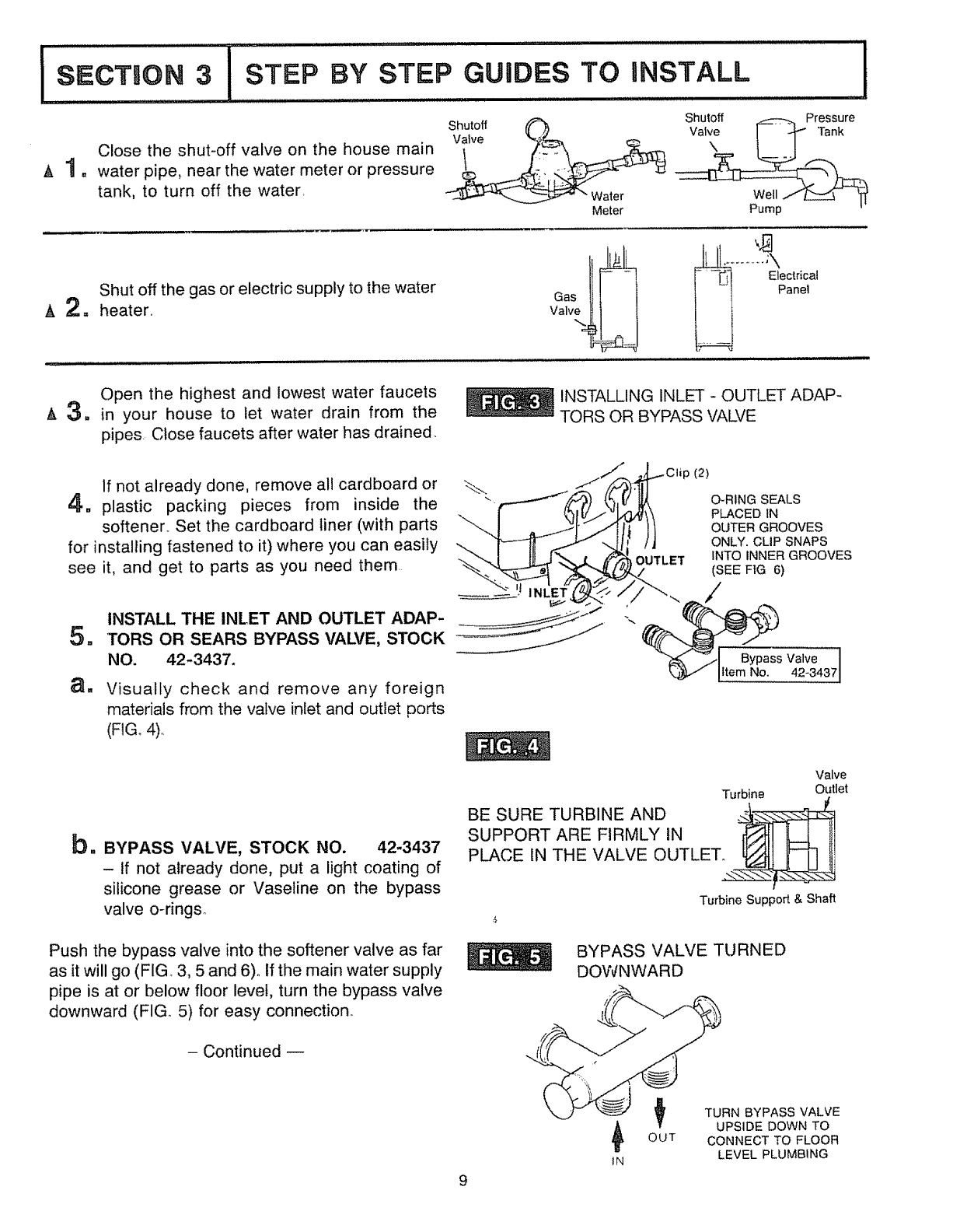
Close the shut-off valve on the house main
&1. water pipe, near the water meter or pressure
tank, to turn off the water,
Shutoff _ Shutoff _---:t-_ Pressure
-_'--4k_'_'r-"-_ "Water Well ..f"_
Meter Pump
Shut off the gas or electric supply to the water
ik 2. heater..
Open the highest and lowest water faucets
/_ 3. in your house to let water drain from the
pipes. Close faucets after water has drained.
INSTALLING INLET - OUTLET ADAP-
TORS OR BYPASS VALVE
/" _J._.._Clip (2)
_If not already done, remove all cardboard or -_. J/_-%..'fiT
_. plastic packing pieces from inside the .-_/_ (._ O-RINGSEALS
"_ I _lv_o_\ PLACEDfN
softener.. Set the cardboard liner (with parts --._.j ,,J-Jl"..-._ I] I I OUTERGROOVES
for installing fastened to it) where you can easily --.. T---I[ /"...Jl[ /J ONLY.CLiPSNAPS
\"-.. I It _,f _'_ J[ _ OUTLET INTO lIMNER GROOVES
see it, and get to parts as you need them _%.__ ff_"__"" (SEE FIG 6)
INSTALL THE INLET AND OUTLET ADAP- " __s
5. TORS OR SEARS BYPASS VALVE, STOCK
NO. 42-3437. v4=, 4371
a. Visually check and remove any foreign
materials from the valve inlet and outlet ports
(FIG. 4).
b. BYPASS VALVE, STOCK NO. 42-3437
- tf not already done, put a light coating of
silicone grease or Vaseline on the bypass
valve o-ringso
Push the bypass valve into the softener valve as far
as it will go (FIG. 3, 5 and 6)° if the main water supply
pipe is at or below floor level, turn the bypass valve
downward (FIG. 5) for easy connection.
- Continued
Turbine
BE SURE TURBINE AND
SUPPORT ARE FIRMLY IN
PLACE IN THE VALVE OUTLET,.
Valve
Outlet
Turbine Support & Shaft
BYPASS VALVE TURNED
DOWNWARD
9
TURN BYPASS VALVE
UPSIDE DOWN TO
OUT CONNECT TO FLOOR
IN LEVEL PLUMBING
!S CTIlON 3ISTEP BY STEP GUIDES TO INSTALL I
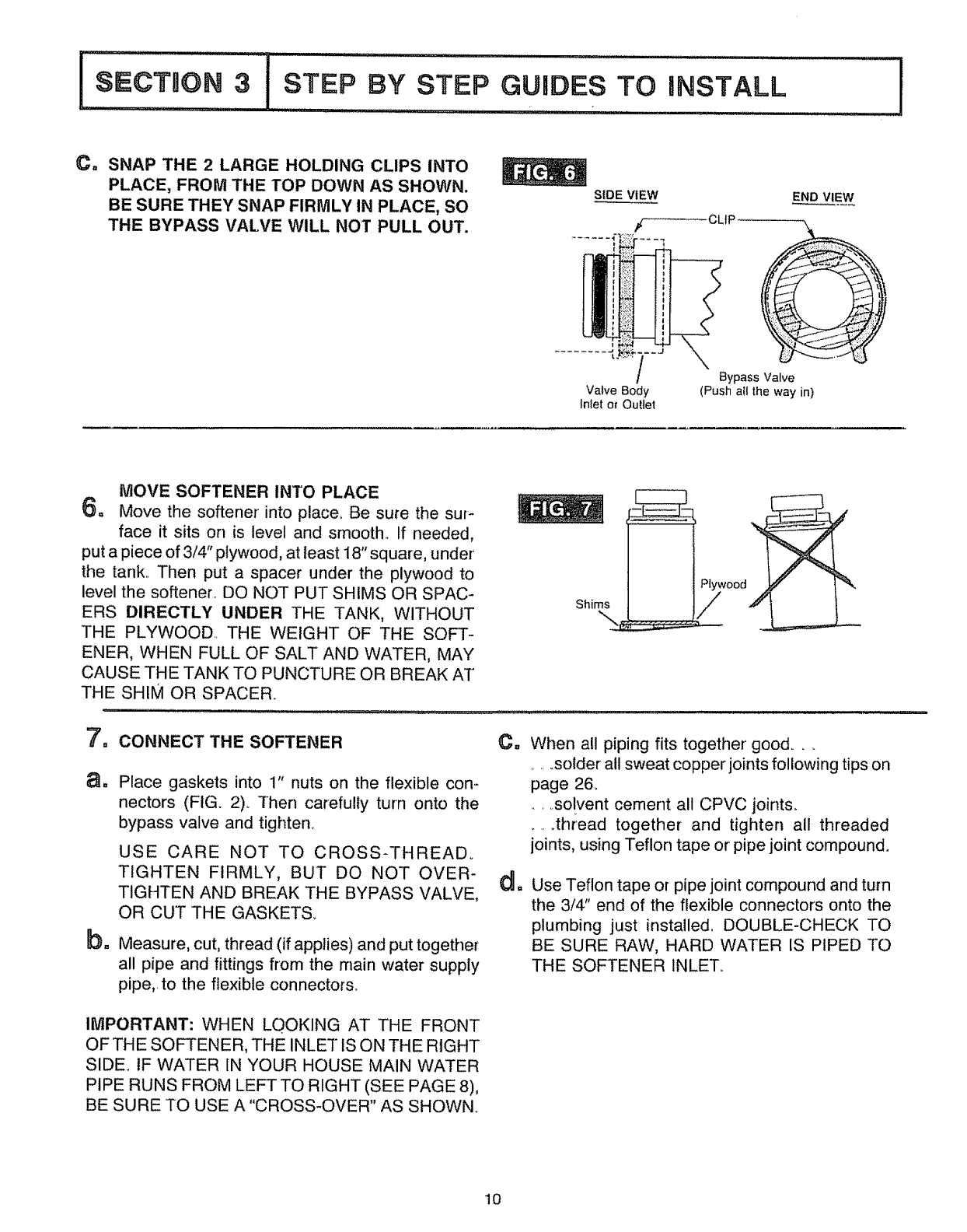
C, SNAP THE 2 LARGE HOLDING CLIPS INTO
PLACE, FROM THE TOP DOWN AS SHOWN.
BE SURE THEY SNAP FIRMLY IN PLACE, SO
THE BYPASS VALVE WILL NOT PULL OUT.
S|DE VIEW
# CLaP
END VIEW
"t t' ,- J
/
Valve Body
Inlet or Outlet
Bypass Valve
(Push atl the way in)
MOVE SOFTENER INTO PLACE
6o Move the softener into place. Be sure the sur-
face it sits on is level and smooth.. If needed,
put a piece of 3/4" plywood, at least 18" square, under'
the tank.. Then put a spacer under the plywood to
level the softener.. DO NOT PUT SHIMS OR SPAC-
ERS DIRECTLY UNDER THE TANK, WITHOUT
THE PLYWOOD.. THE WEIGHT OF THE SOFT-
ENER, WHEN FULL OF SALT AND WATER, MAY
CAUSE THE TANK TO PUNCTURE OR BREAK AT
THE SHIM OR SPACER.
Shims
Plywood
/
btl
CONNECT THE SOFTENER
Place gaskets into 1" nuts on the flexible con-
nectors (FIG. 2).. Then carefully turn onto the
bypass valve and tighten.
USE CARE NOT TO CROSS-THREADo
TIGHTEN FIRMLY, BUT DO NOT OVER-
TIGHTEN AND BREAK THE BYPASS VALVE,
OR CUT THE GASKETS_
Measure, cut, thread (if applies) and put together
all pipe and fittings from the main water supply
pipe,, to the flexible connectors.
Ca When all piping fits together good..
......solder all sweat copper joints following tips on
page 26.
.... solvent cement all CPVC joints.
.... thread together and tighten all threaded
joints, using Teflon tape or pipe joint compound.
Use Teflon tape or pipe joint compound and turn
the 3/4" end of the flexible connectors onto the
plumbing just installed, DOUBLE-CHECK TO
BE SURE RAW, HARD WATER IS PIPED TO
THE SOFTENER INLET°
IMPORTANT: WHEN LO.OKING AT THE FRONT
OFTHE SOFTENER, THE INLET IS ON THE RIGHT
SIDE. tF WATER IN YOUR HOUSE MAIN WATER
PIPE RUNS FROM LEFT TO RIGHT (SEE PAGE 8),
BE SURE TO USE A "CROSS-OVER" AS SHOWN.
10
I SECTION 3iSTEP
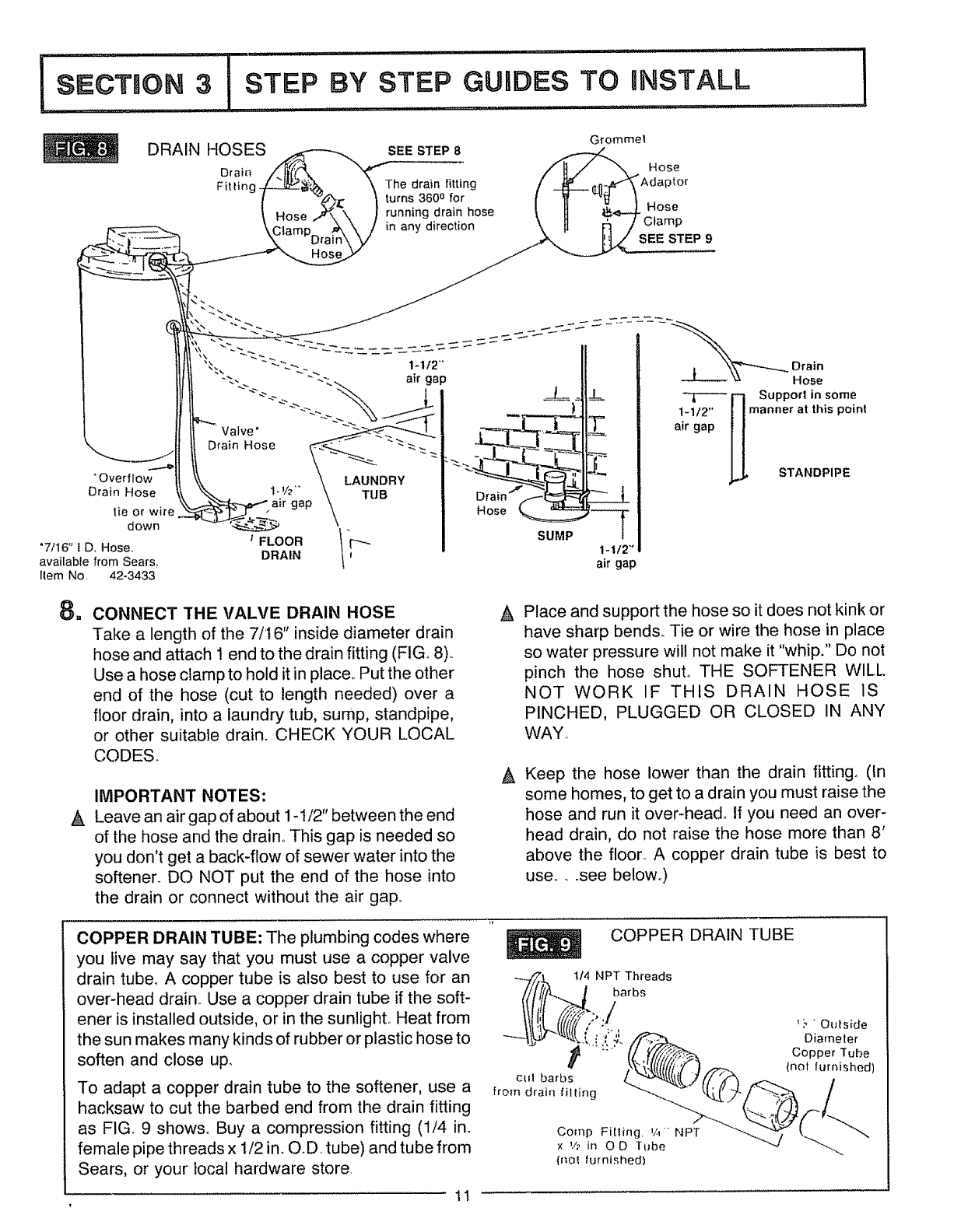
DRAIN HOSES
Drain
Fitting,
BY STEP GUIDES TO INSTALL
Grommel
SEE STEP 8
Hose
The drain fitting "Adaptor
turns 3600 for
running drain hose Hose
in any direction SEE STEP 9
i
°Overflow
Drain Hose
tie or wire
down
"7116" i D. Hose,
available from Sears.
Ilem No. 42-3433
1-1/2"' Drain
Hose
Z
1.112"°
air gap
r] support in some
1.112 ,0 Hmanner at this point
air gap
STANDPIPE
m
A
CONNECT THE VALVE DRAIN HOSE
Take a length of the 7/t6" inside diameter drain
hose and attach 1 end to the drain fitting (FIG., 8).
Use a hose clamp to hold it in place,. Put the other
end of the hose (cut to length needed) over a
floor drain, into a laundry tub, sump, standpipe,
or other suitable drain. CHECK YOUR LOCAL
CODES
IMPORTANT NOTES:
Leave an air gap of about 1-1/2" between the end
of the hose and the drain° This gap is needed so
you don't get a back-flow of sewer water into the
softener. DO NOT put the end of the hose into
the drain or connect without the air gap°
APlace and support the hose so it does not kink or
have sharp bends,. Tie or wire the hose in place
so water pressure wil! not make it "whip," Do not
pinch the hose shut. THE SOFTENER WILL
NOT WORK IF THIS DRAIN HOSE 1S
PINCHED, PLUGGED OR CLOSED IN ANY
WAY.,
Keep the hose lower than the drain fitting, (In
some homes, to get to a drain you must raise the
hose and run it over-head_ If you need an over-
head drain, do not raise the hose more than 8'
above the floor. A copper drain tube is best to
user..see below_)
COPPER DRAIN TUBE: The plumbing codes where
you live may say that you must use a copper valve
drain tube, A copper tube is also best to use for an
over-head drain., Use a copper drain tube if the soft-
ener is installed outside, or in the sunNghto Heat from
the sun makes many kinds of rubber or plastic hose to
soften and close up.
To adapt a copper drain tube to the softener, use a
hacksaw to cut the barbed end from the drain fitting
as FIG. 9 shows,. Buy a compression fitting (1/4 in,.
female pipe threads x 1/2 in_ O.D.. tube) and tube from
Sears, or your local hardware store.
COPPER DRAIN TUBE
_,,.fZt 114 NPT Threads
/tlli7-.._1Oa,s
ill I_>,,/
..[,.[ ,,'.;'_._ Diameter
_i +" (I V'/,_ CopperT_he
u _7_Z/6'/'_.._.. tool furnishod)
•c,,thart,s /._..S(( _ _.... /
oo,oo
x '/2 in O D _ube ..... ""'J
(nol furnished)
11
II...........s ...............................I
3 STEP BY TEP GUIDES TO INSTALL
=, ,=ll i ii i,,H H =
u
CONNECT A SALT TANK OVERFLOW
HOSE
it in place, Put the other end of the hose over the
floor drain_
a= Take the rubber grommet, hose adaptor and
hose clamp (FIGo 8) that are on the small parts
cardboard liner_
bo Push the grommet into the hole in the salt tank
wall so half is inside and half is outside°
C. Push the bigger end of the hose adaptor into the
grommett,
d= Push one end of a length of 7/16" I,D. hose onto
the hose adaptor, using the hose clamp to hold
IMPORTANT NOTES:
®The salt tank overflow is for safety only, If the salt
tank should overfill with water, the overflow hose
carries it to the drain,
®Over-fill water must run downward through the
hose_ Do not raise the hose higher than the
grommet and hose adaptor (FIG 8).
®DO NOT connect to the valve drain hose you
installed in step 9A separate hose is needed for
both drains.
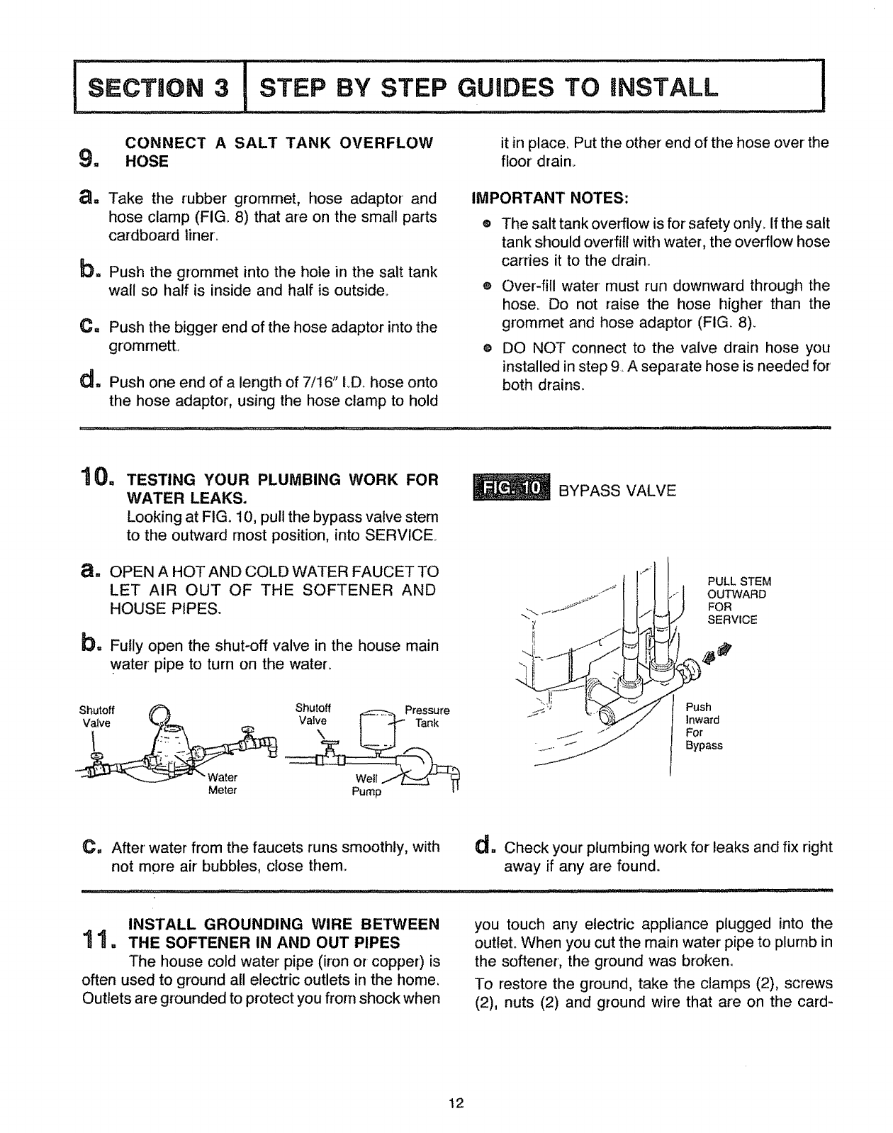
10. TESTING YOUR PLUMBING WORK FOR
WATER LEAKS,
Looking at FIG. 10, pull the bypass valve stem
to the outward most position, into SERVICE
8. OPEN A HOT AND COLD WATER FAUCET TO
LET AIR OUT OF THE SOFTENER AND
HOUSE PIPES.
b. Fully open the shut-off valve in the house main
water pipe to turn on the water.
BYPASS VALVE
PULL STEM
OUTWARD
FOR
SERVICE
Shutoff
Valve
Shuloff '_ PUsh
inward
For
Bypass
Meter Pump
C. After' water from the faucets runs smoothly, with
not more air bubbles, close them. d=Check your plumbing work for leaks and fix right
away if any are found.
INSTALL GROUNDING WIRE BETWEEN
1 "I • THE SOFTENER IN AND OUT PIPES
The house cold water pipe (iron or copper) is
often used to ground all electric outlets in the horne,
Outlets are grounded to protect you from shock when
you touch any electric appliance plugged into the
outlet° When you cut the main water pipe to plurnb in
the softener, the ground was broken.
To restore the ground, take the clamps (2), screws
(2), nuts (2) and ground wire that are on the card-
12
SECTBON 3iSTEP BY STEP GUHDES TO INSTALL !
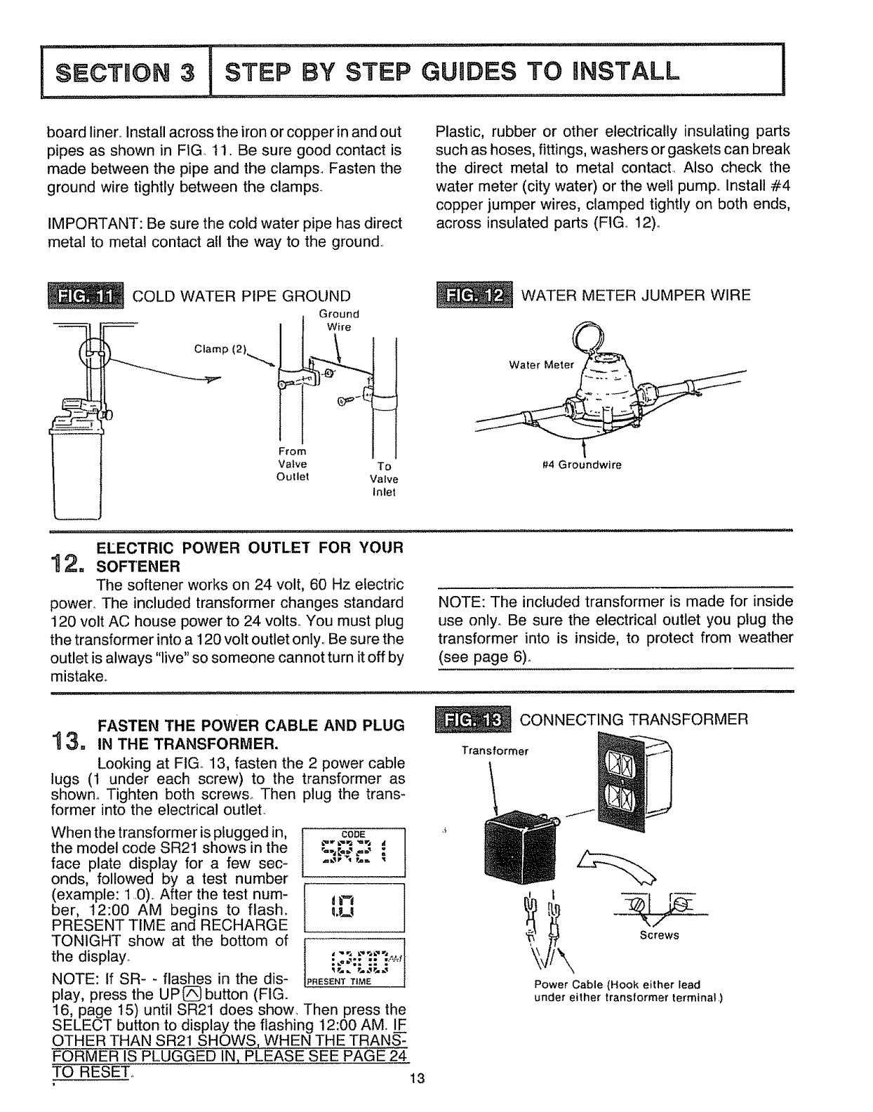
board liner.. Install across the iron or copper in and out
pipes as shown in FIG.. 1! ..Be sure good contact is
made between the pipe and the clamps. Fasten the
ground wire tightly between the clamps.
IMPORTANT: Be sure the cold water pipe has direct
metal to metal contact atl the way to the ground.
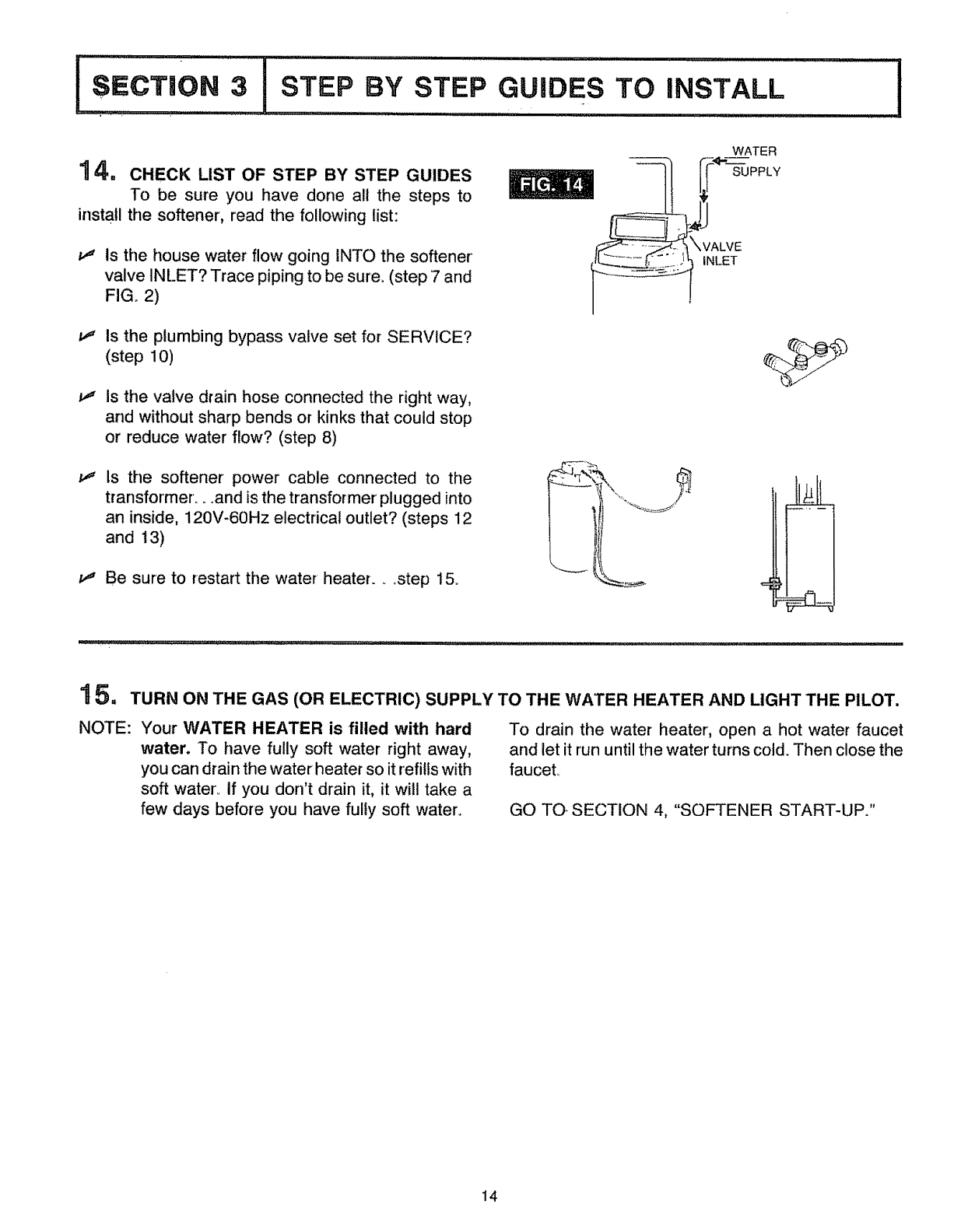
Plastic, rubber or other electrically insulating parts
such as hoses, fittings, washers or gaskets can break
the direct metal to metal contact. Also check the
water meter (city water) or the welt pump° Install #4
copper jumper wires, clamped tightly on both ends,
across insulated parts (FIG.. 12)_
COLD WATER PIPE GROUND
Ground
" Wire
p 12t,.....,....
From
Valve
Outlet To
Valve
Inlet
WATER METER JUMPER WIRE
Water Meter
#4 Groundwire
ELECTR,CPOWEROUTLETFORYOUR
12. SOFTENER
The softener works on 24 volt, 60 Hz electric
power° The included transformer changes standard
120 volt AC house power to 24 volts. You must plug
the transformer into a 120 volt outlet only. Be sure the
outlet is always "live" so someone cannot turn it off by
mistaken
NOTE: The included transformer is made for inside
use onlyo Be sure the electrical outlet you plug the
transformer into is inside, to protect from weather
(see page 6).
FASTEN THE POWER CABLE AND PLUG
13. ,NTHETRANSFORMER.
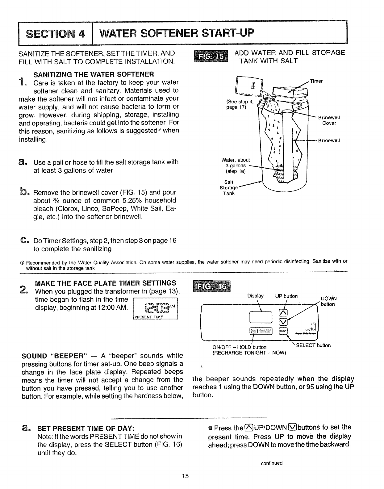
Looking at FIG 13, fasten the 2 power cable
lugs (1 under each screw) to the transformer as
shown_ Tighten both screws. Then plug the trans-
former into the electrical outlet.
When the transformer is plugged in,
the model code SR21 shows in the
face plate display for a few sec-
onds, followed by a test number
(example: 1 O).. After the test num-
ber, t2:00 AM begins to flash,
PRESENT TIME and RECHARGE
TONIGHT show at the bottom of
the display.
NOTE: If SR- - flashes in the dis-
play, press the UP(_ button (FIG.
ICODE
q.Ll
PRESENT T ME
16, page 15) until SR21 does show. Then press the
SELECT button to display the flashing 12:00 AM. IF
OTHER THAN SR21 SHOWS, WHEN THE TRANS-
FORMER IS PLUGGED IN, PLEASE SEE PAGE 24
TO RESET_
CONNECTING TRANSFORMER
Transformer
/
i_-_ Screws
Power Cable (Hook either Iead
under either transformer terminal,)
, 13
iNSTALL !
1 4, CHECK LIST OF STEP BY STEP GUIDES
To be sure you have done all the steps to
install the softener, read the following list:
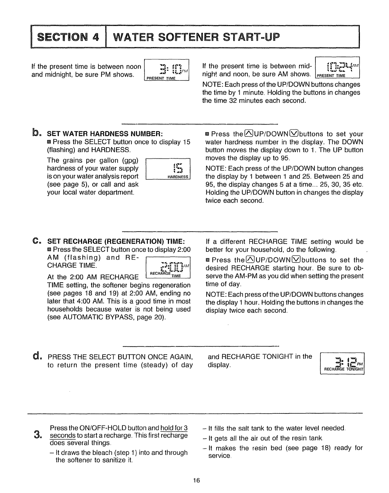
tt Is the house water flow going INTO the softener
valve INLET? Trace piping to be sure. (step 7 and
FIG_ 2)
_" Is the plumbing bypass valve set for SERVICE?
(step 10)
Is the valve drain hose connected the right way,
and without sharp bends or kinks that could stop
or reduce water flow? (step 8)
Is the softener power cable connected to the
transformer...and is the transformer' plugged into
an inside, 120V-60Hz electrical outlet? (steps 12
and 13)
_" Be sure to restart the water heater. ....step t5_
WATER
1 5. TURN ON THE GAS (OR ELECTRIC) SUPPLY TO THE WATER HEATER AND LIGHT THE PILOT.
NOTE: Your WATER HEATER is filled with hard
water. To have fully soft water right away,
you can drain the water heater so itrefills with
soft water, If you don't drain it, it will take a
few days before you have fully soft water.
To drain the water heater, open a hot water faucet
and let it run until the water turns cold. Then close the
faucet.
GO TO SECTION 4, "SOFTENER START-UP."
14
SANITIZE THE SOFTENER, SET THE TIMER, AND
FILL WITH SALT TO COMPLETE INSTALLATION.
ADD WATER AND FILL STORAGE
TANK WITH SALT
SANITIZING THE WATER SOFTENER
1. Care is taken at the factory to keep your water
softener clean and sanitary_ Materials used to
make the softener will not infect or contaminate your
water supply, and will not cause bacteria to form or
grow. However, during shipping, storage, installing
and operating, bacteria could get into the softener. For
this reason, sanitizing as follows is suggested '_when
installing,,
(See step 4,
page 17)
Cover
trinewell
a. Use a pail or hose to fill the salt storage tank with
at least 3 gallons of water..
b= Remove the brinewell cover (FIG, 15) and pour
about 3/4 ounce of common 5,25% household
bleach (Clorox, Linco, BoPeep, White Sail, Ea-
gle, etc,) into the softener brinewetL
Water, about
3 galIons
(step la)
Sat!
Stocag
Tank
C. Do Timer Settings, step 2, then step 3 on page 16
to complete the sanitizing,,
O Recommended by the Water Quality Association. On some water supplies, the water softener may need periodic disinfecting., Sanitize with or
without salt in the storage tank , ,.
m
MAKE THE FACE PLATE TIMER SETTINGS
When you plugged the transformer in (page 13),
time began to flash in the time [
display, beginning at ! 2:00 AM,, f :.o...'- .'-..'_'_
[PRESENT TiME
SOUND "BEEPER" w A "beeper" sounds while
pressing buttons for timer set-up. One beep signals a
change in the face plate display. Repeated beeps
means the timer wilt not accept a change from the
button you have pressed, telling you to use another
button., For example, while setting the hardness below,
Disptay UP button DOW'N
_ button
ON/OFF - HOLDtbutton \ SELECT bulton
(RECHARGE TONIGHT - NOW)
4
the beeper sounds repeatedly when the display
reaches 1 using the DOWN button, or 95 using the UP
button.
a_ SET PRESENT TIME OF DAY:
Note: If the words PRESENT TIME do not show in
the display, press the SELECT button (FIG. 16)
until they do.
aPress the [_UP/DOWN[_buttons to set the
present time° Press UP to move the display
ahead; press DOWN to move the time backward,
continued
15
If the present time is between noon
and midnight, be sure PM shows. ++. ...i_4
1
PRESENT TiME |
If the present time is between mid ........ ,._. _.;..,._-,
night and noon, be sure AM shows,, paEsE.TTime
NOTE: Each press of the UP/DOWN buttons changes
the time by 1 minute+ Holding the buttons in changes
the time 32 minutes each second.
ba SET WATER HARDNESS NUMBER:
[] Press the SELECT button once to display 15
(flashing) and HARDNESS.
The grains per gallon (gpg) ]
hardness of your water supply !;_, !
is on your water analysis report .ARO.ESS
(see page 5), or call and ask
your local water department
m Press the[_UP/DOWN(_buttons to set your
water hardness number in the display. The DOWN
button moves the display down to 1. The UP button
moves the display up to 95,
NOTE: Each press of the UP/DOWN button changes
the display by 1 between 1 and 25, Between 25 and
95, the display changes 5 at atime .....25, 30, 35 etc+
Holding the UP/DOWN button in changes the display
twice each second°
Cm SET RECHARGE (REGENERATION) TIME:
[] Press the SELECT button once to display 2:00
AM (flashing) and RE+ [
CHARGE TIME+ " 3.:"'_-"%r._l
[t+'cl_ plJ, +- _ 'I
At the 2:00 AM RECHARGE "_CHARa%+MEI
TIME setting, the softener begins regeneration
(see pages 18 and 19) at 2:00 AM, ending no
later that 4:00 AM+ This is a good time in most
households because water is not being used
(see AUTOMATIC BYPASS, page 20)+
If a different RECHARGE TIME setting would be
better for your household, do the following
[] Press the[_UP/DOWN(_buttons to set the
desired RECHARGE starting hour_ Be sure to ob-
serve the AM-PM as you did when setting the present
time of day,
NOTE: Each press of the UP/DOWN buttons changes
the display 1 hour. Holding the buttons in changes the
display twice each second+
_. PRESS THE SELECT BUTTON ONCE AGAIN,
to return the present time (steady) of day
and RECHARGE TONIGHT in the
display,. ,==]
RECHARGE TONIGHT I
a
Press the ON/OFF-HOLD button and hold for3
seconds to start a recharge° This first recharge
does several things,
- It draws the bleach (step 1) into and through
the softener to sanitize it
-It fills the salt tank to the water-level needed.
- It gets all the air out of the resin tank,
-it makes the resin bed (see page 18) ready for
service,,
16
FILL THE STORAGE TANK WITH SALT
4= Fill the tank with NUGGET or PELLET water
softener salt. DO NOT use rock salts, (See page 22
and NOTE following).. Before filling, BE SURE THE
BRtNEWELL COVER IS IN PLACE (FIG. 15). It takes
about 230 Ibso of salt to fill the tank° Replace the salt
storage tank cover after filling
NOTE: WATER SOFTENING SALT WITH
IRON REMOVING ADDITIVES - Some salts
have an additive to help the softener handle iron
in the water supply. Although this additive may
help to keep the softener resin clean, it may also
release corrosive fumes that will weaken and
shorten the life of some softener parts°
I
THE SOFTENER INSTALLATION AND START-UP STEPS ARE COMPLETE. PAGES 18 THROUGH 31
FOLLOWING, TELL. YOU HOW THE SOFTENER WORKS, AND HOW YOU CAN HELP TO MAINTAIN IT.
17
OTHER FACE PLATE TIMER FEATURES
EXTRA RECHARGE
Sometimes, a manually started regeneration (re-
charge) may be desired, or needed. Two examples
are__
....You have used more water than usual (guests visit-
ing) and you may run out of soft water before the next
timer started regeneration,.
.....You did not refill the softener with salt before it was
gone.
You can start a regeneration right away, or you can set
the timer to regenerate at the next 2:00 AM (or other
preset recharge time) Do the following,,
RECHARGE NOW
{a Press the ON/OFF-HOLD button and hold
for 3 seconds.. RECHARGE o__q_t_q
NOW begins to flash in the dis- _. q_.,H_
play, and the softener enters the .EC.A.G_NOW
fill cycle of regeneration right
away, This regeneration will last from 72 to 108
minutes, then you will have soft water' again,
RECHARGE TONIGHT
Press and release (DO NOT HOLD) the ON!
OFF-HOLD button. RECHARGE [ ]
TONIGHT flashes in the display, _._ d'_q2HM
and the softener begins regener- RECHARGETONIGHT|
ation at the next preset recharge
time_ Press and release the ON!OFF-HOLD button
once more if you decide to cancel the regenera-
tion, and RECHARGE TONIGHT,,
PROGRAM MEMORY
If electrical power to the softener goes off, the time
display is blank but the face plate timer keeps the
correct time for about 6 hours. When electrical power
comes on again, you have to reset the present time
only if the display is flashing. The HARDNESS and
RECHARGE TIME never require resetting unless a
change is desired
Even if the timer is incorrect after a long power outage,
the softener works as it should to keep your water soft,.
However, regenerations may occur atthe wrong time of
day until you reset the timer to the correct time of day,
ERROR CODE
An error' code could appear in the face plate display if a
problem occurs in the softener elec- Ii
tronics, if you see an error code in- )_) )= Lql!_= _l
stead of the present time of day, please call your' local
Sears Service Department for service,
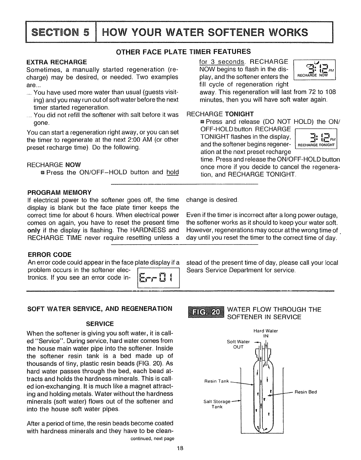
SOFT WATER SERVICE, AND REGENERATION
SERVICE
When the softener' is giving you soft water, it is call-
ed "Service". During service, hard water comes from
the house main water pipe into the softener. Inside
the softener' resin tank is a bed made up of
thousands of tiny, plastic resin beads (FIG 20),. As
hard water passes through the bed, each bead at-
tracts and holds the hardness minerals° This is call-
ed ion-exchangingo It is much like a magnet attract-
ing and holding metals. Water without the hardness
minerals (soft water) flows out of the softener and
into the house soft water pipe&
After a period of time, the resin beads become coated
with hardness minerals and they have to be clean-
continued, next page
18
WATER FLOW THROUGH THE
SOFTENER tN SERVICE
Sott Water
OUT
Resin Tank
Sail Storage
Tank
Hard Waler
IN
..,--,- Resin Bed
IsEcTioNSIHOW YOUR WATER SOFTENER WORKS I
ed. This cleaning is called regeneration or recharge
Regeneration is started at 2:00 a.m by the electronic
timer (See page 16)It takes place in 5 stages or
cycles. These are:
[-_ FILL I_] BACKWASH
[2] BRINING [] FAST RINSE
I-'3-] BRINE RINSE
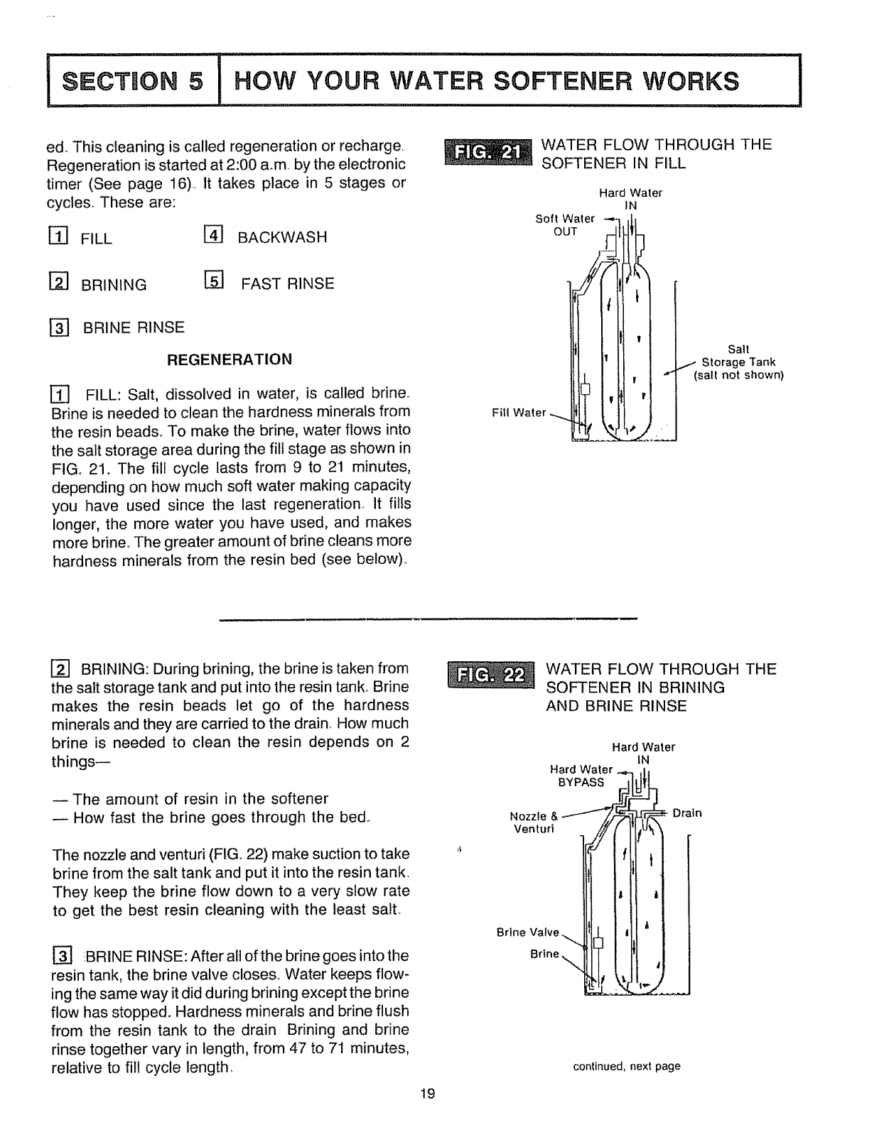
REGENERATION
[_ FILL: Salt, dissolved in water, is called brine.
Brine is needed to clean the hardness minerals from
the resin beads_ To make the brine, water flows into
the salt storage area during the fill stage as shown in
FIGo 21. The fill cycle lasts from 9 to 21 minutes,
depending on how much soft water making capacity
you have used since the last regeneration° It fills
longer, the more water you have used, and makes
more brine The greater amount of brine cleans more
hardness minerals from the resin bed (see below).
WATER FLOW THROUGH THE
SOFTENER IN FILL
Hard Water
IN
Soft Water _ ,/-
OUT I
FillWater
Salt
..,..- Storage Tank
(salt not shown)
[] BRINING: During brining, the brine is taken from
the salt storage tank and put into the resin tank° Brine
makes the resin beads let go of the hardness
minerals and they are carried to the drain. How much
brine is needed to clean the resin depends on 2
things--
The amount of resin in the softener
How fast the brine goes through the bed_
The nozzle and venturi (FIG 22) make suction to take
brine from the salt tank and put it into the resin tank.
They keep the brine flow down to a very slow rate
to get the best resin cleaning with the least salt.
[] !BRINE RINSE: After all of the brine goes into the
resin tank, the brine valve closes, Water keeps flow-
ing the same way it did during brining except the brine
flow has stopped. Hardness minerals and brine flush
from the resin tank to the drain Brining and brine
rinse together vary in length, from 47 to 71 minutes,
relative to fill cycle length.
19
Nozzle
Venturi
Brine
Brine.
WATER FLOW THROUGH THE
SOFTENER IN BRINING
AND BRINE RINSE
Hard
BYPASS
Hard Water
tN
Drain
continued, next page
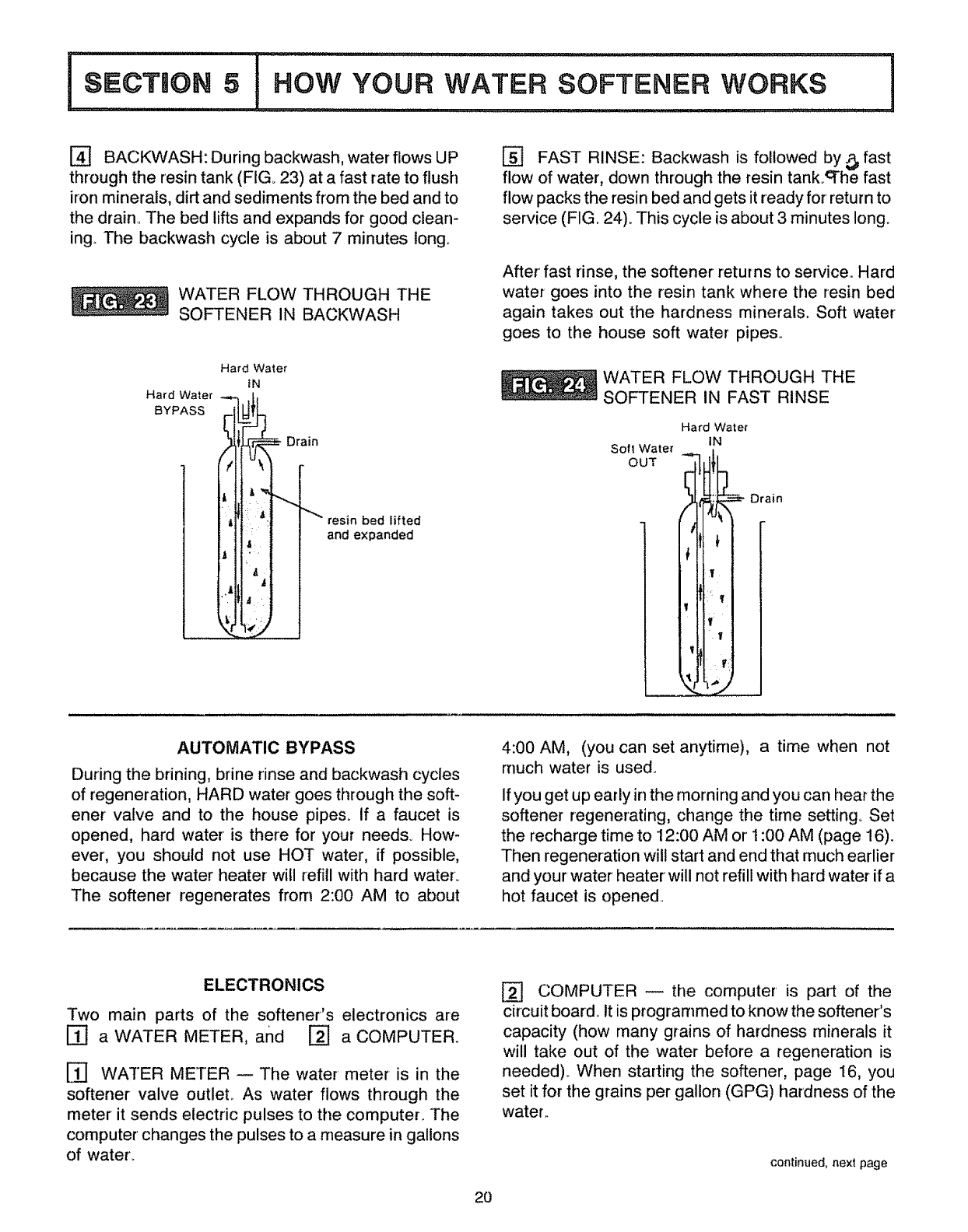
l°oo..o.° .o.,,....!
[] BACKWASH: During backwash, water flows UP
through the resin tank (FIG. 23) at a fast rate to flush
iron minerals, dirt and sediments from the bed and to
the drain. The bed lifts and expands for good clean-
ing.. The backwash cycle is about 7 minutes long..
WATER FLOW THROUGH THE
SOFTENER IN BACKWASH
Hard Water
BYPASS
Hard Water
IN
Drain
resin bed lifted
and expanded
[] FAST RINSE: Backwash is followed by _ fast
flow of water, down through the resin tank._he fast
flow packs the resin bed and gets it ready for return to
service (FIG. 24). This cycle is about 3 minutes long.
After fast rinse, the softener returns to service.. Hard
water goes into the resin tank where the resin bed
again takes out the hardness minerals. Soft water
goes to the house soft water pipes..
WATER FLOW THROUGH THE
SOFTENER IN FAST RINSE
Hard Water
IN
Soft Water
OUT "' -- Drain
AUTOMATIC BYPASS
During the brining, brine rinse and backwash cycles
of regeneration, HARD water goes through the soft-
ener valve and to the house pipes° If a faucet is
opened, hard water is there for your needs. How-
ever, you should not use HOT water, if possible,
because the water heater will refill with hard water_
The softener regenerates from 2:00 AM to about
4:00 AM, (you can set anytime), a time when not
much water is used.
If you get up early in the morning and you can hear the
softener regenerating, change the time setting. Set
the recharge time to 12:00 AM or1:00 AM (page 16).
Then regeneration will start and end that much earlier
and your water heater will not refill with hard water if a
hot faucet is opened.
ELECTRONICS
Two main parts of the softener's electronics are
[-_ a WATER METER, and r-2] a COMPUTER.
[_ WATER METER -- The water meter is in the
softener valve outleL As water flows through the
meter it sends electric pulses to the computer.. The
computer changes the pulses to a measure in gallons
of water..
[_ COMPUTER -- tile computer' is part of the
circuit board. It is programmed to know the softener's
capacity (how many grains of hardness minerals it
will take out of the water before a regeneration is
needed).. When starting the softener, page 16, you
set it for the grains per gallon (GPG) hardness of the
water..
continued, next page
20
The computer uses, (1) water usage from the meter,
(2) hardness setting, (3) softener capacity, and (4)
time since the last regeneration, to find a regenera-
tion pattern best for your needs,, The computer al-
ways adjusts this pattern to your water using habits,
It works toward providing you with soft water for the
longest time and the most efficient salt usage_
As hard water goes through the softener and hard-
hess minerals are removed, capacity is use& When
the computer determines only enough capacity re-
mains to provide soft water up to the next regenera-
tion starting time (2:00 AM, or as otherMse set) it will
schedule a regeneration, RECHARGE TONIGHT
displays until the regeneration begins. When the
regeneration begins, TONIGHT goes off and RE-
CHARGE NOW flashes during the regeneration,
which lasts between 72 and 108 minutes,
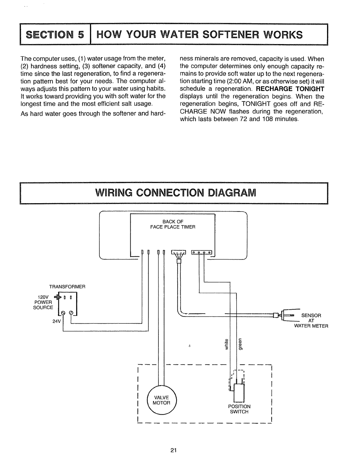
iWRRRNGCONNECTnON DIAGRAM
TRANSFORMER
I
i
t 20V
POWER I I
24V I {.............
[, ,,,,, _
BACK OF
FACE PLACE TIMER
r-
POSITION
SWITCH
1
t
1
1
1
J
I
SENSOR
AT
WATER METER
2t
i,;,c,,oo,....,,,,,.! OF YOUR SOFTENER I
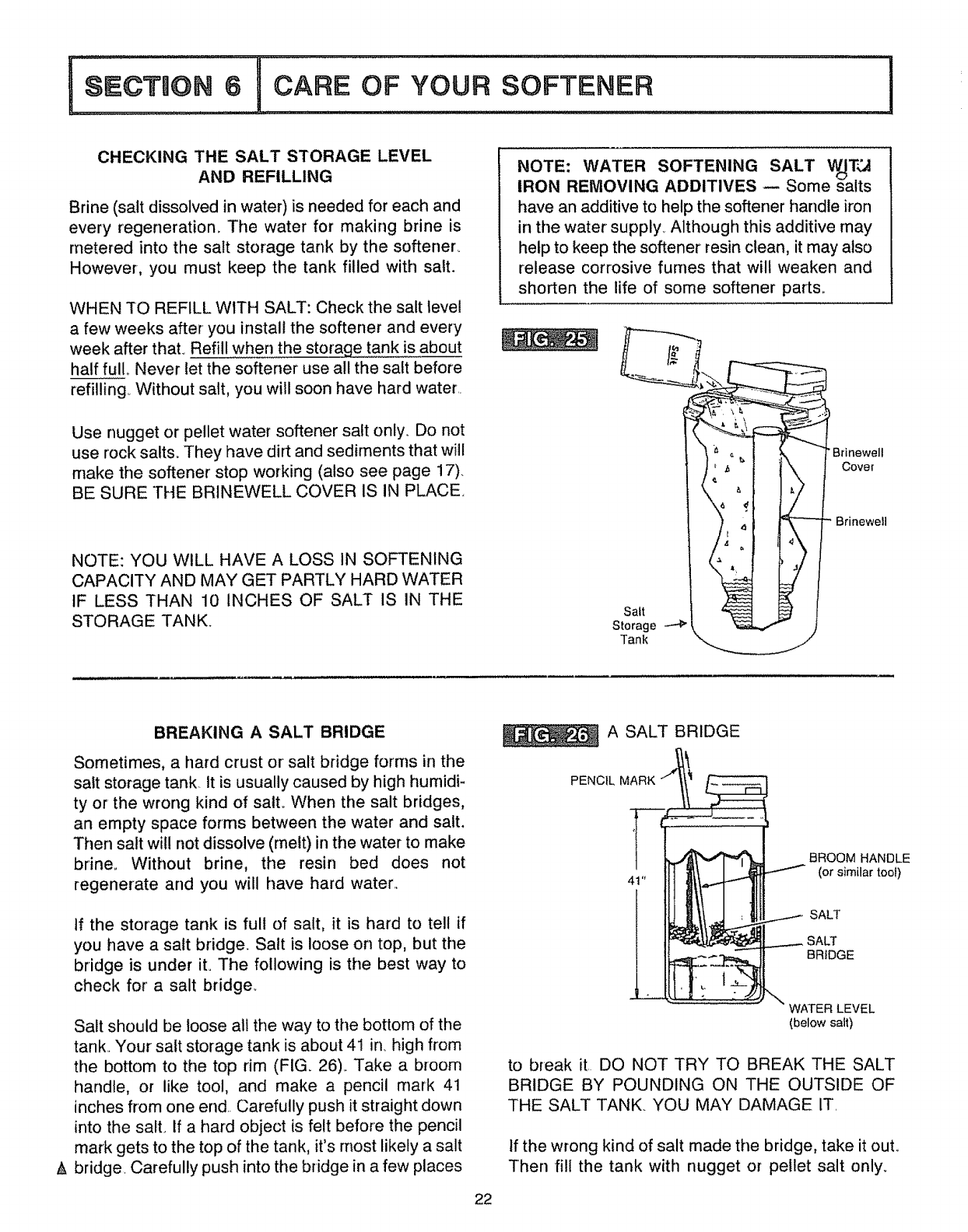
CHECKING THE SALT STORAGE LEVEL
AND REFILLING
Brine (salt dissolved in water) is needed for each and
every regeneration. The water for making brine is
metered into the salt storage tank by the softener.
However, you must keep the tank filled with salt.
WHEN TO REFILL WITH SALT: Check the salt level
a few weeks after you install the softener and every
week after that. Refill when the storaqe tank is about
half full Never let the softener use all the salt before
refilling Without salt, you will soon have hard water.
Use nugget or pellet water softener salt only. Do not
use rock salts. They have dirt and sediments that will
make the softener stop working (also see page 17).
BE SURE THE BRINEWELL COVER IS IN PLACE.
NOTE: YOU WILL HAVE A LOSS IN SOFTENING
CAPACITY AND MAY GET PARTLY HARD WATER
IF LESS THAN 10 INCHES OF SALT IS IN THE
STORAGE TANK.
NOTE: WATER SOFTENING SALT _T3
IRON REMOVING ADDITIVES -- Some salts
have an additive to help the softener handle iron
in the water supply. Although this additive may
help to keep the softener resin clean, it may also
release corrosive fumes that will weaken and
shorten the life of some softener parts,.
Brinewelt
Cover
Salt
Storage
Tank
/
Brinewell
BREAKING A SALT BRIDGE
Sometimes, a hard crust or' salt bridge forms in the
salt storage tank. tt is usually caused by high humidi-
ty or the wrong kind of satto When the salt bridges,
an empty space forms between the water and salt.
Then salt will not dissolve (melt) in the water to make
brine., Without brine, the resin bed does not
regenerate and you will have hard water.,
If the storage tank is full of salt, it is hard to tell if
you have a salt bridge. Salt is loose on top, but the
bridge is under ito The following is the best way to
check for a salt bridge_
Salt should be loose all the way to the bottom of the
tank., Your satt storage tank is about 4! in. high from
the bottom to the top rim (FIG_ 26)_ Take a broom
handle, or like tool, and make a pencil mark 41
inches from one end Carefully push it straight down
into the salt. tf a hard object is felt before the pencil
mark gets to the top of the tank, it's rnost likely a salt
A bridge. Carefully push into the bridge in a few places
22
A SALT BRIDGE
PENCIL MARK
BROOM HANDLE
(or similar tool)
SALT
SALT
BRIDGE
WATER LEVEL
(below salt)
to break it, DO NOT TRY TO BREAK THE SALT
BRIDGE BY POUNDING ON THE OUTSIDE OF
THE SALT TANK. YOU MAY DAMAGE IT,
If the wrong kind of salt made the bridge, take it out..
Then fill the tank with nugget or pellet salt only.
6 ! CARE OF YOUR SOF'FENEF I
CLEANING THE COVERS
To keep your new Sears water softener looking nice,
apply a coat of paste wax and repeat once a year.
When dusty, wipe it with a damp cloth to keep it
sparkling.
A Never use cleaners having ammonia or abrasives_
They may scratch and dull the surface,.
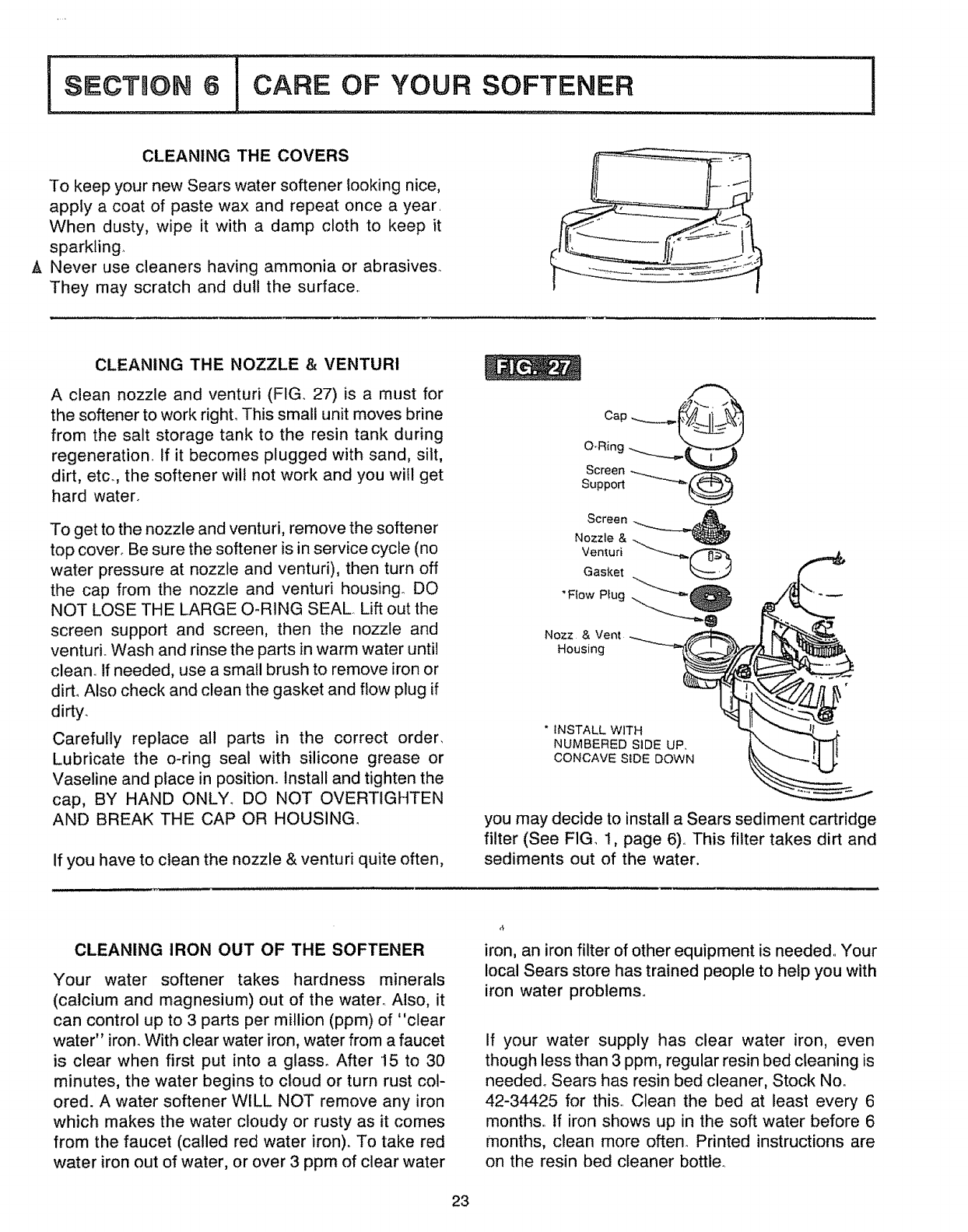
CLEANING THE NOZZLE & VENTURI
A clean nozzle and venturi (FIG.. 27) is a must for
the softener to work righL This small unit moves brine
from the salt storage tank to the resin tank during
regeneration.. If it becomes plugged with sand, silt,
dirt, etc. the softener wilt not work and you will get
hard water°
To get to the nozzle and venturi, remove the softener
top cover° Be sure the softener is in service cycle (no
water pressure at nozzle and venturi), then turn off
the cap from the nozzle and venturi housing. DO
NOT LOSE THE LARGE O-RING SEAL. Lift out the
screen support and screen, then the nozzle and
venturio Wash and rinse the parts in warm water until
clean_ If needed, use a small brush to remove iron or
dirt° Also check and clean the gasket and flow plug if
dirty.
Carefully replace all parts in the correct order_
Lubricate the o-ring seal with silicone grease or
Vaseline and place in position. Install and tighten the
cap, BY HAND ONLY_ DO NOT OVERTIGHTEN
AND BREAK THE CAP OR HOUSING.
If you have to clean the nozzle & venturi quite often,
Screen
Support
Screen
Nozzle &
Venturi
Gasket
"Flow Plug
Nozz & Vent
Housing
*INSTALL WITH
NUMBERED SIDE UP,
CONCAVE SiDE DOWN
you may decide to install a Sears sediment cartridge
filter (See FIG 1, page 6),, This filter takes dirt and
sediments out of the water,
CLEANING IRON OUT OF THE SOFTENER
Your water softener takes hardness minerals
(calcium and magnesium) out of the water° Also, it
can control up to 3 parts per million (ppm) of "clear
water" iron. With clear water iron, water from a faucet
is clear when first put into a glass. After 15 to 30
minutes, the water begins to cloud or turn rust col-
ored. A water softener WELL NOT remove any iron
which makes the water cloudy or rusty as it comes
from the faucet (called red water iron). To take red
water iron out of water, or over 3 ppm of clear water
iron, an iron filter of other equipment is needed,. Your
local Sears store has trained people to help you with
iron water problems°
If your water supply has clear water iron, even
though less than 3 ppm, regular resin bed cleaning is
needed° Sears has resin bed cleaner, Stock No.
42-34425 for this,. Clean the bed at least every 6
months, tf iron shows up in the soft water before 6
months, clean more often. Printed instructions are
on the resin bed cleaner bottle°
23
KEEP THE SOFTENER FROM FREEZING
If the softener' is installed where it could freeze
(summer cabin, lake home, etco), you must drain all
water from it to stop poSsible freeze damage. To
drain the softener--
1o Close the shut-off valve on the house main water
pipe, near the water' meter or pressure tank.
2 Open a faucet in the soft water pipes to vent
pressure in the softener'.
3o Looking at FIG. 10 on page 12, move the bypass
valve stem to bypass.
(if you want water in the house pipes again,
reopen the shut*off valve on the main water pipe)..
4. Unplug the transformer at the wall outlet.. Take
off both drain hoses.
5. Carefully remove the large holding clips (see step
5c, page 10, and separate the bypass valve from
the softener.
& Take offthe salt tank and brinewell cover.. Discon-
nect the brine valve tubing at the nozzle and
venturi assembly (See page 30) and lift the brine
valve out of the brinewello Tip the brine valve
upside down to drain out water..
74
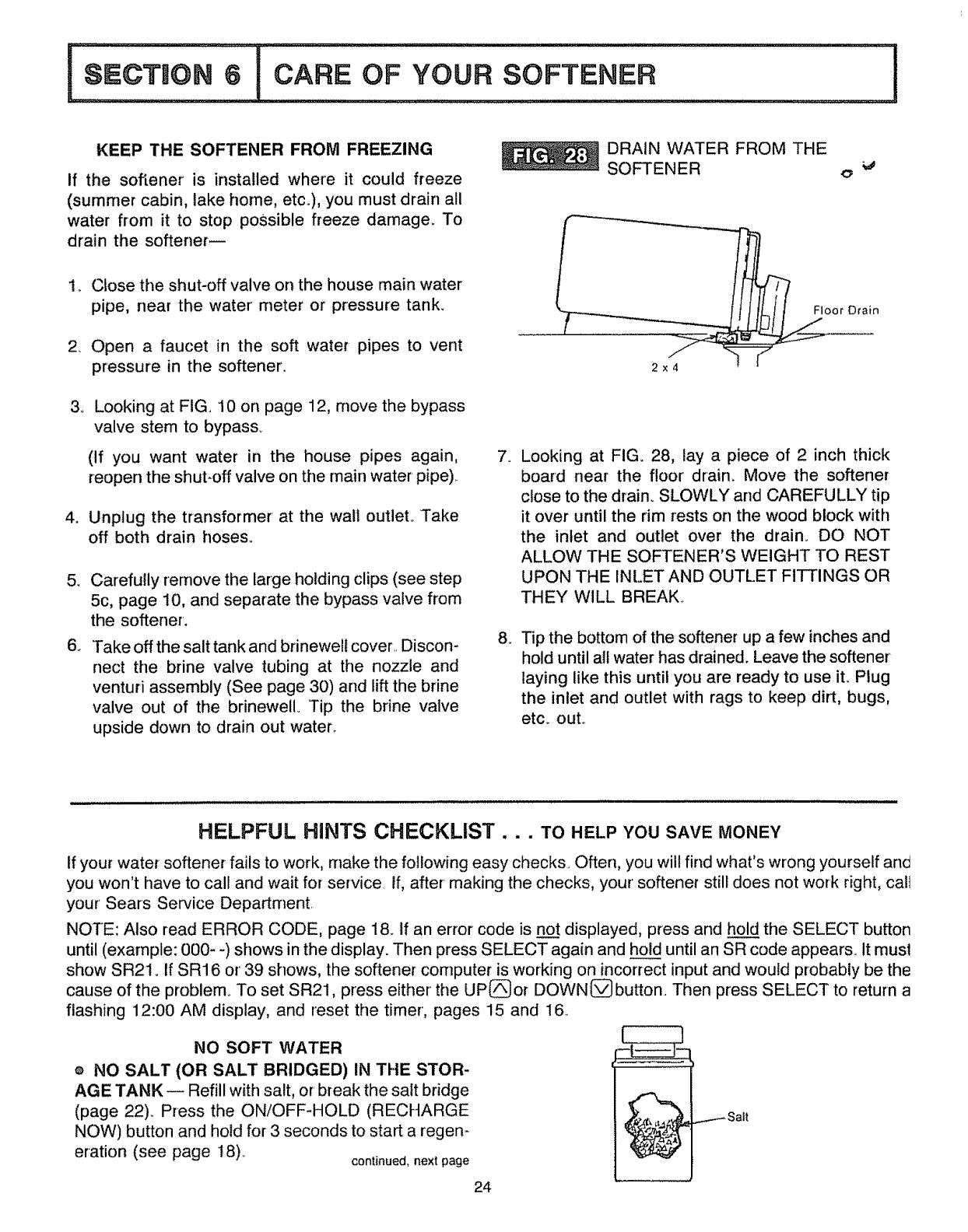
8_
DRAIN WATER FROM THE
SOFTENER e _
I
2x4
Floor Drain
Looking at FIG. 28, lay a piece of 2 inch thick
board near the floor drain. Move the softener
close to the drain. SLOWLY and CAREFULLY tip
it over until the rim rests on the wood block with
the inlet and outlet over the drain° DO NOT
ALLOW THE SOFTENER'S WEIGHT TO REST
UPON THE INLET AND OUTLET FITTINGS OR
THEY WILL BREAK.
Tip the bottom of the softener up a few inches and
hold until all water has drained. Leave the softener
laying like this until you are ready to use it. Plug
the inlet and outlet with rags to keep dirt, bugs,
etc.. out..
HELPFUL HINTS CHECKLIST... TO HELPYOUSAVEMONEY
If your water softener fails to work, make the following easy checks. Often, you will find what's wrong yourself and
you won't have to call and wait for service If, after making the checks, your softener still does not work right, call
your Sears Service Department.
NOTE: Also read ERROR CODE, page 18. If an error code is no__ttdisplayed, press and hold the SELECT button
until (example: 000- -) shows in the display. Then press SELECT again and ho until an SR code appears° it rnusl
show SR21. If SR16 or 39 shows, the softener computer is working on incorrect input and would probably be the
cause of the problem. To set SR21, press either the UP(_or DOWN(_button. Then press SELECT to return a
flashing 12:00 AM display, and reset the timer, pages 15 and 16.
NO SOFT WATER
e NO SALT (OR SALT BRIDGED) IN THE STOR-
AGE TANK _ Refill with salt, or break the salt bridge
(page 22). Press the ON/OFF-HOLD (RECHARGE
NOW) button and hold for 3 seconds to start a regen-
eration (see page 18).. continued, next page
24
SECTBON 6 CARE OF YOUR SOFTENER !
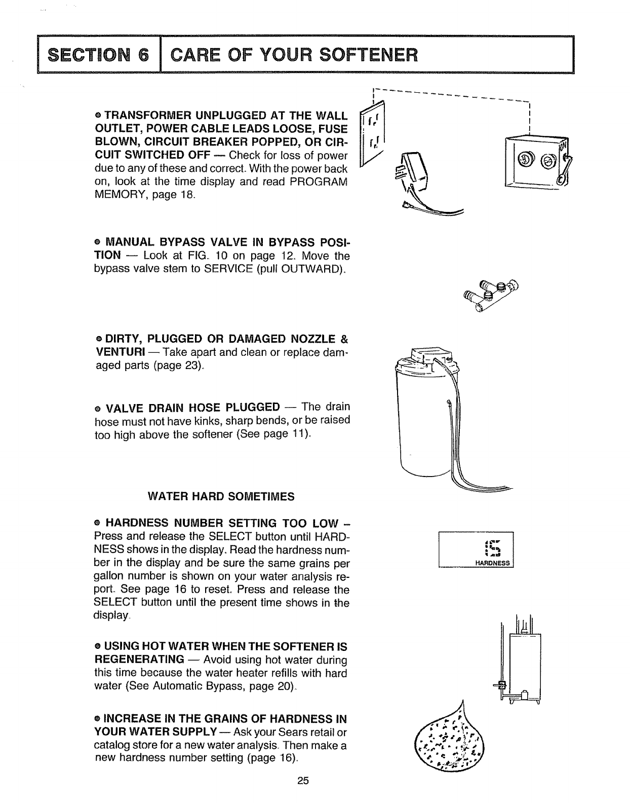
e TRANSFORMER UNPLUGGED AT THE WALL
OUTLET, POWER CABLE LEADS LOOSE, FUSE
BLOWN, CIRCUIT BREAKER POPPED, OR CIR-
CUIT SWITCHED OFF m Check for loss of power
due to any of these and correct,. With the power back
on, look at the time display and read PROGRAM
MEMORY, page 18.
!
® MANUAL BYPASS VALVE IN BYPASS POSI-
TION _Look at FIG.. 10 on page 12o Move the
bypass valve stem to SERVICE (pull OUTWARD),.
e DIRTY, PLUGGED OR DAMAGED NOZZLE &
VENTURi _ Take apart and clean or replace dam-
aged parts (page 23)..
® VALVE DRAIN HOSE PLUGGED _ The drain
hose must not have kinks, sharp bends, or be raised
too high above the softener (See page 11)_
WATER HARD SOMETIMES
® HARDNESS NUMBER SETTING TOO LOW-
Press and release the SELECT button until HARD-
NESS shows in the display° Read the hardness num-
ber in the display and be sure the same grains per
gallon number is shown on your water analysis re-
port_ See page !6 to reset° Press and release the
SELECT button until the present time shows in the
disptay_
® USING HOT WATER WHEN THE SOFTENER IS
REGENERATING _ Avoid using hot water during
this time because the water heater refills with hard
water (See Automatic Bypass, page 20)_
® INCREASE IN THE GRAINS OF HARDNESS IN
YOUR WATER SUPPLY _ Ask your Sears retail or
catalog store for a new water analysis. Then make a
new hardness number setting (page 16)..
25
HARDNESS
1OTHER
.................................. _lJ/I
THINGS TO KNOW i
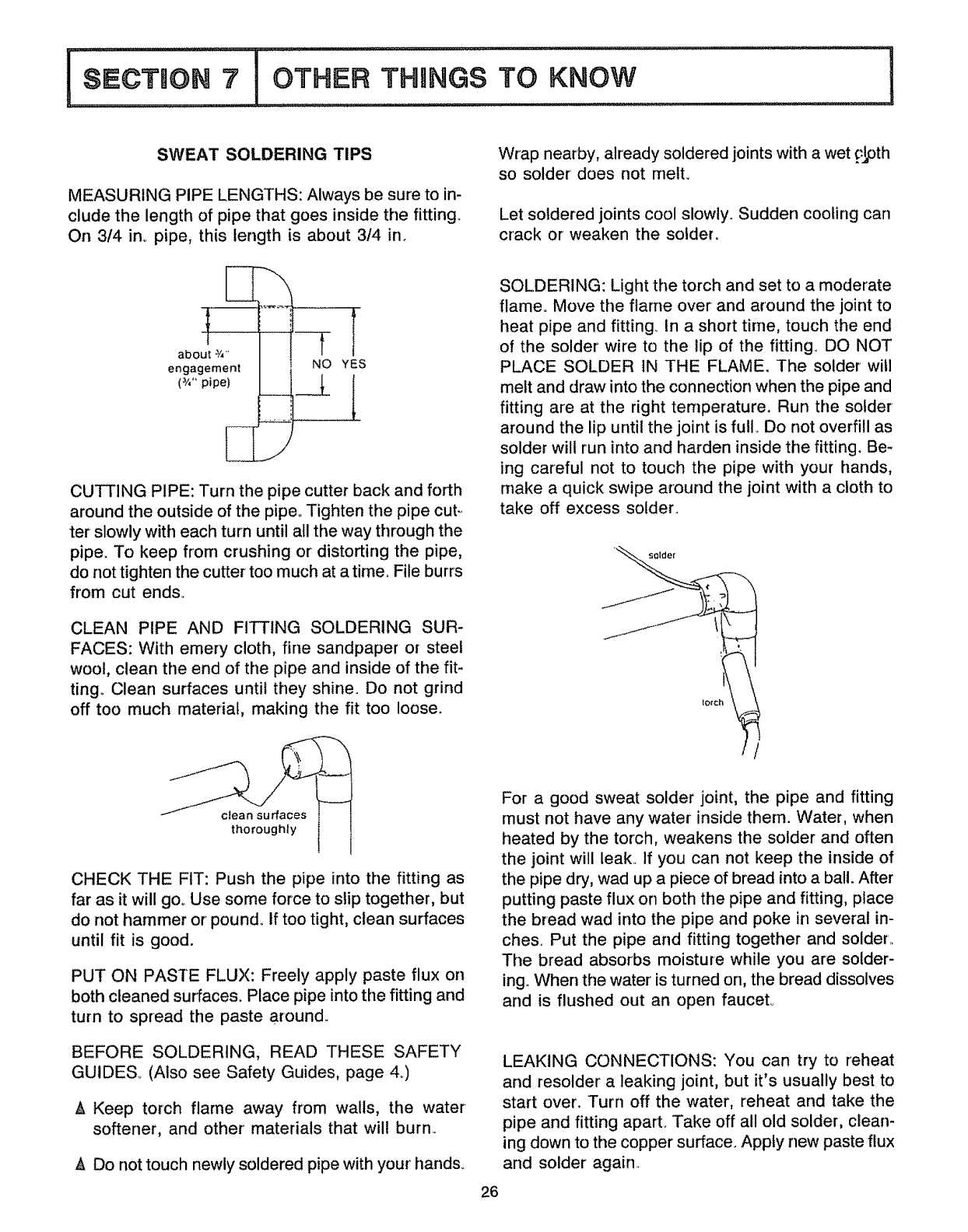
SWEAT SOLDERING TIPS
MEASURING PIPE LENGTHS: Always be sure to in-
clude the length of pipe that goes inside the fitting.
On 3/4 in. pipe, this length is about 3/4 in.
Wrap nearby, already soldered joints with a wet _l,pth
so solder does not melt.
Let soldered joints cool slowly. Sudden cooling carl
crack or weaken the solder.
about _/4'
engagement
(_/," pipe)
...
YES
CUTTING PIPE: Turn the pipe cutter back and forth
around the outside of the pipe,, Tighten the pipe cut-
ter slowly with each turn until all the way through the
pipe. To keep from crushing or distorting the pipe,
do not tighten the cutter too much at a time. File burrs
from cut ends.
CLEAN PIPE AND FITTING SOLDERING SUR-
FACES: With emery cloth, fine sandpaper or steel
wool, clean the end of the pipe and inside of the fit-
ting,, Clean surfaces until they shine. Do not grind
off too much material, making the fit too loose.
thoroughly
CHECK THE FIT: Push the pipe into the fitting as
far as it will goo Use some force to stip together, but
do not hammer or' pound, if too tight, clean surfaces
until fit is good.
PUT ON PASTE FLUX: Freely apply paste flux on
both cleaned surfaces. Place pipe into the fitting and
turn to spread the paste around,.
BEFORE SOLDERING, READ THESE SAFETY
GUIDES° (Also see Safety Guides, page 4.)
A Keep torch flame away from walls, the water
softener, and other materials that will burn..
A Do not touch newly soldered pipe with your hands.
26
SOLDERING: Light the torch and set to a moderate
flame. Move the flame over and around the joint to
heat pipe and fitting. In a short time, touch the end
of the solder wire to the lip of the fitting. DO NOT
PLACE SOLDER IN THE FLAME. The solder will
melt and draw into the connection when the pipe and
fitting are at the right temperature. Run the solder
around the lip until the joint is full. Do not overfill as
solder will run into and harden inside the fitting. Be-
ing careful not to touch the pipe with your hands,
make a quick swipe around the joint with a cloth to
take off excess solder,
solder
For a good sweat solder joint, the pipe and fitting
must not have any water inside them. Water, when
heated by the torch, weakens the solder and often
the joint will leak, If you can not keep the inside of
the pipe dry, wad up a piece of bread into a ball. After
putting paste flux on both the pipe and fitting, place
the bread wad into the pipe and poke in several in-
ches. Put the pipe and fitting together and solder,
The bread absorbs moisture while you are solder-
ing. When the water is turned on, the bread dissolves
and is flushed out an open faucet°
LEAKING CONNECTIONS: You can try to reheat
and resolder a leaking joint, but it's usually best to
start over. Turn off the water, reheat and take the
pipe and fitting apart. Take off all old solder, clean-
ing down to the copper surface. Apply new paste flux
and solder again.
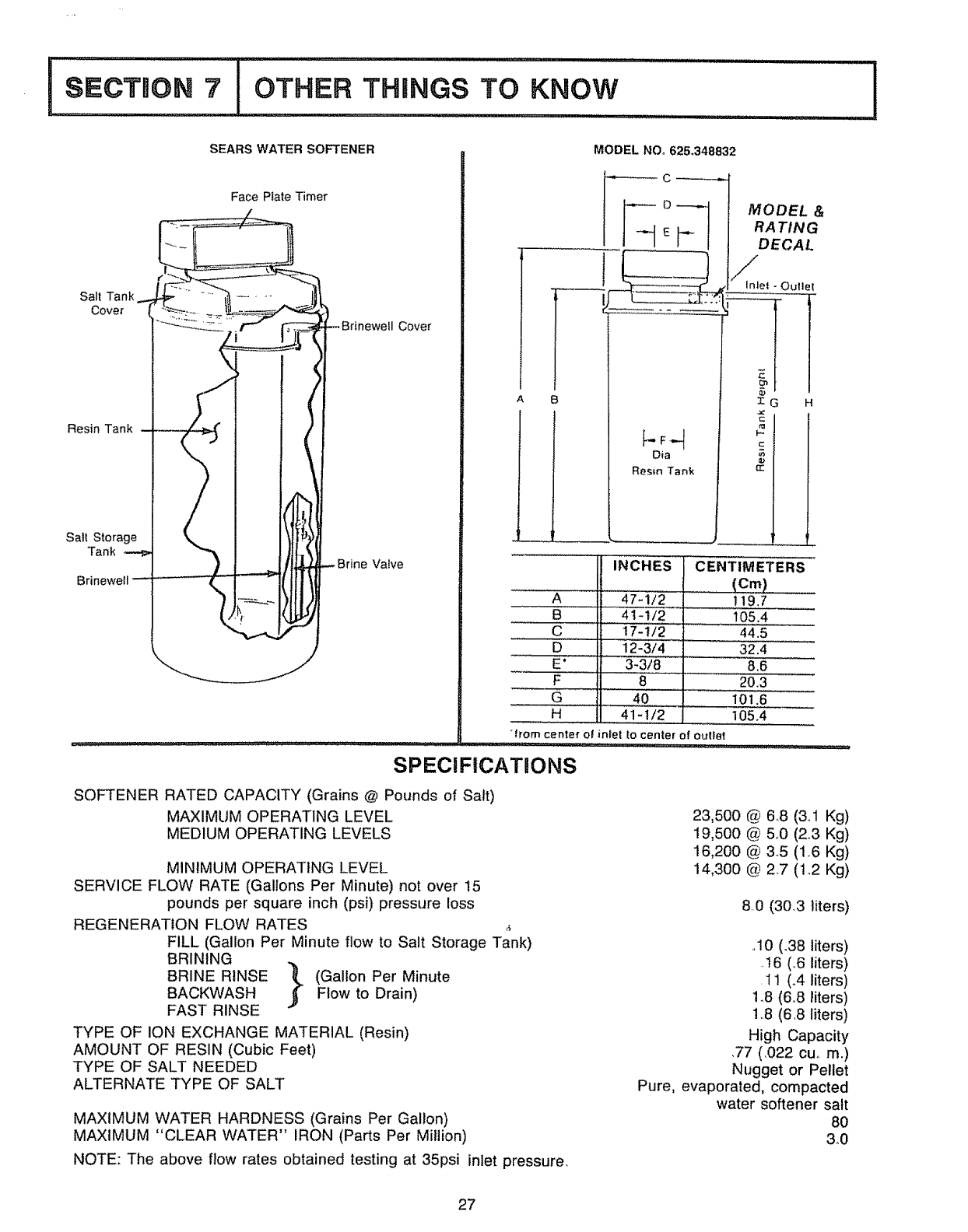
SEARS WATER SOFTENER MODEL NOo 625°348832
Salt Tank....
Cover
Resin Tank
Salt Storage
Tank
Brinewe!l
Face Plate Timer
--Brinewell Cover
(
_. -Brine Valve
A
I
C _
A
B
C
D
E •
F
G
H
F-Fr._]
Dia
Resin Tank
MODEL &
RA TIN G
DECAL
/Inlel - Oullel
IG H
c
INCHES
47-1/2
4t-tf2
17-112
12-3/4
3-3/8
8
40
41-!/2
CENTIMETERS
(Cm)......
t!9.7
105.4
44.5
32.4
8,6
20.3
101.6
105.4
"from center o! inlet to center of outlet
SPECIFiCATiONS
SOFTENER RATED CAPACITY (Grains @ Pounds of Salt)
MAXIMUM OPERATING LEVEL
MEDIUM OPERATING LEVELS
MINIMUM OPERATING LEVEL
SERVICE FLOW RATE (Gallons Per Minute) not over 15
pounds per square inch (psi) pressure loss
REGENERATION FLOW RATES ._
FILL (Gallon Per Minute flow to Salt Storage Tank)
BRINING
BRINE RINSE 1_ (Gallon Per Minute
BACKWASH ._" Flow to Drain)
FAST RINSE
TYPE OF ION EXCHANGE MATERIAL (Resin)
AMOUNT OF RESIN (Cubic Feet)
TYPE OF SALT NEEDED
ALTERNATE TYPE OF SALT
MAXIMUM WATER HARDNESS (Grains Per Gallon)
MAXIMUM "CLEAR WATER" IRON (Parts Per Million)
NOTE: The above flow rates obtained testing at 35psi inlet pressure.
23,500 @ 648 (3,1 Kg)
19,500 @ 5_0 (23 Kg)
16,200 @ 35 (1_6 Kg)
14,300 @ 2.7 (1.,2 Kg)
80 (303 liters)
.10 (.38 liters)
.16 (,,6 liters)
I1 (.4 liters)
1.8 (6,,8 liters)
1o8(6,8 liters)
High Capacity
,77 (,022 cur m.)
Nugget or Pellet
Pure, evaporated, compacted
water softener salt
8O
3.0
!
27
3!
IsooT,o.81
32
29
............. : :: : :.......... :ll llll i,ti,llluli
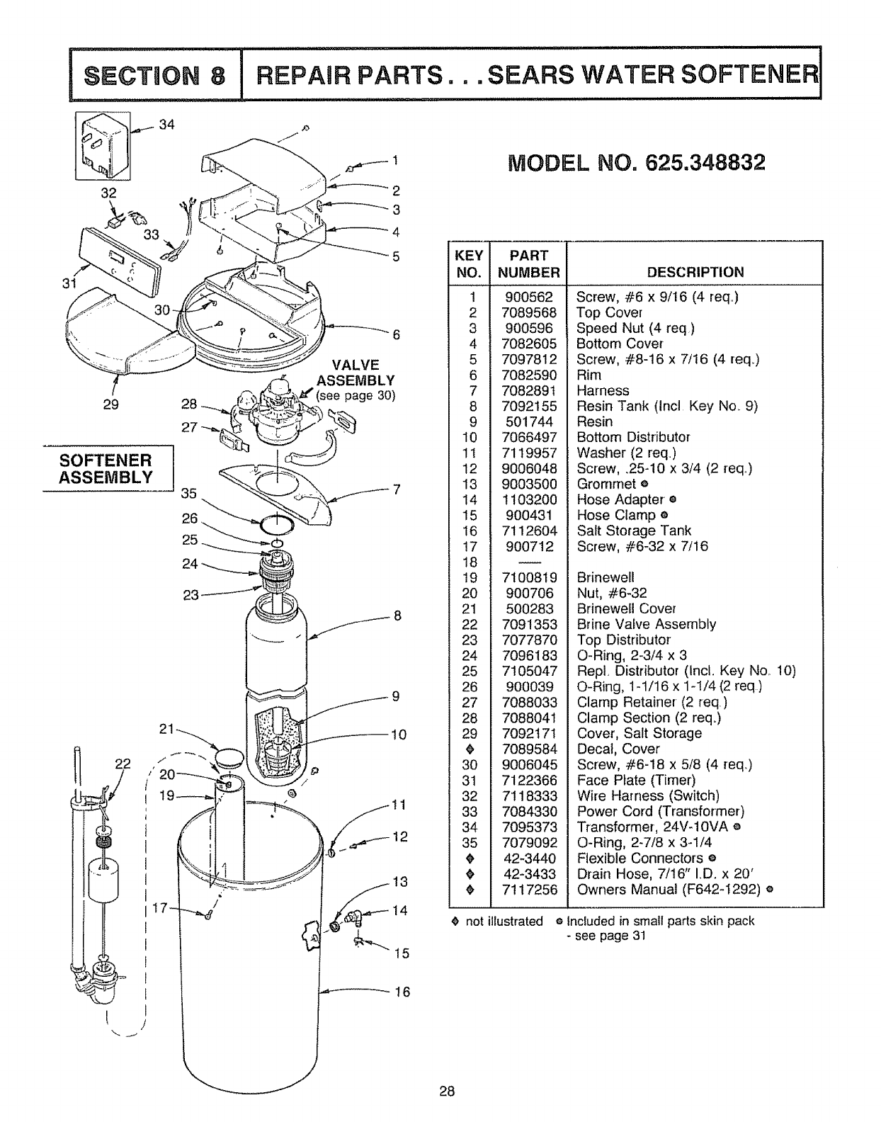
REPAIR PARTS... SEARS WATER
i iJll ii i ij i j ii ii i jl ij iii iiiii
SOFTENER
ASSEMBLY
34
p
/
10
!1
MODEL NO. 625.348832
KEY PART -
NO. NUMBER
1 900562
2 7089568
3 900596
4 7082605
5 7097812
6 7082590
7 7082891
8 7092155
9 501744
10 7066497
1t 7119957
12 9006048
13 9003500 Gromm_
14 1103200 Hose A(
15 900431 Hose CI
16 7112604 Salt StoJ
!7 900712 Screw,
18
19 7100819 Brinewe
20 900706 Nut, #6.
21 500283 Brinewe
22
23
24
25
26
27
28
29
3O
31
32
33
34
35
DESCRIPTION
Screw, #6 x 9/16 (4 req,)
Top Co_
Speed Nut (4 req,)
Bottom Cover
Screw, _8-16 x 7/16 (4 req_)
Rim
Harness
Resin Tank (Incl Key No.. 9)
Resin
Bottom Distributor
Washer (2 req)
Screw, .25-10 x 3/4 (2 req..)
o
ptere
p®
ge Tank
_6-32 x 7/16
Cover
7091353
7077870
7096183
7105047
900039
7088033
7088041
7092171
7089584
9006045
7122366
7118333
7084330
7095373
7079092
42-3440
42-3433
7117256
Brine Valve Assembly
Top Distributor
O-Ring, 2-3/4 x 3
Repl, Distributor (tnct. Key No.. !0)
O-Ring, 1-t/t6 x 1_!/4 (2 req)
Clamp Retainer (2 req)
Clamp Section (2 reqo)
Cover, _;alt Storage
Decal, Cover
Screw, /,6-18 x 5!8 (4 req.)
Face Ptl (Timer)
Wire Harness (Switch)
Power Cord (Transformer)
Transfor ,24V- 1OVA e
O-Ring, 2-7/8 x 3-1/4
Flexible Connectors e
Drain Hose, 7/16" I.D. x 20'
Owners Manual (F642-1292) e
¢ not illustrated e Included in small parts skin pack
-see page 31
__16
28
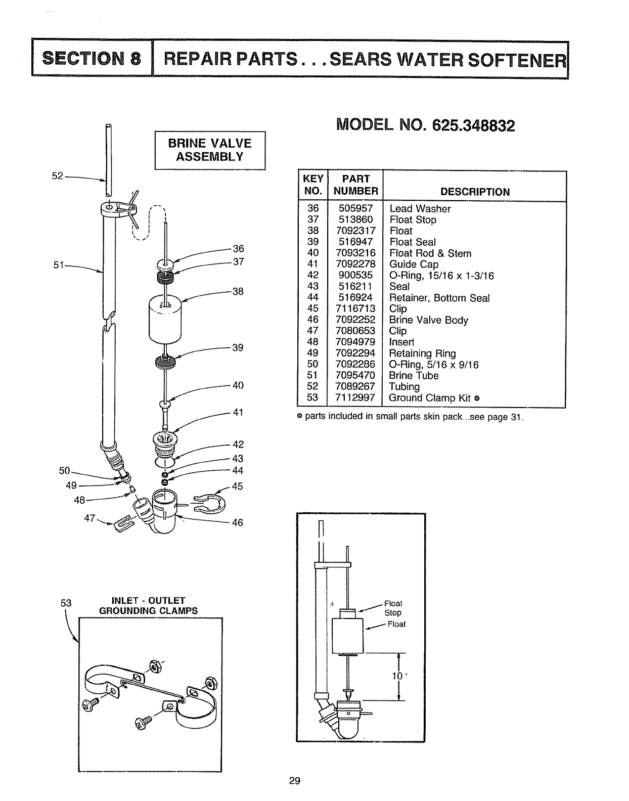
BRINE VALVE
36
MODEL NO. 825.348832
KEY
NO,
36
37
38
39
4O
41
42
43
44
45
46
47
48
49
5O
51
52
53
PART
NUMBER
505957
51386O
7092317
516947
7093216
7092278
900535
516211
516924
7116713
7092252
7080653
7094979
7092294
7092286
7095470
7089267
7112997
DESCRIPTION
................. , ,,,,,,,
Lead Washer
Float Stop
Float
Float Seal
Float Rod & Stem
Guide Cap
O-Ring, 15/16 x 1_3/16
Seal
Retainer, Bottom Seal
Clip
Brine Valve Body
Clip
Insert
Retaining Ring
O-Ring, 5/16 x 9/16
Brine Tube
Tubing
Ground Clamp Kit e
eparts included in smalf parts skin pack ,see page 31o
53
\INLET ,, OUTLET
GROUNDING CLAMPS
29
iu ill illlll iillllllll,/¸
SECTION 8 IREPAIR PARTS.
88_--__
86
85
84 _="
\
82
81
98 j
80 79
78
l
94
93
92
(Bypass Valve)
(See page 31)
3O
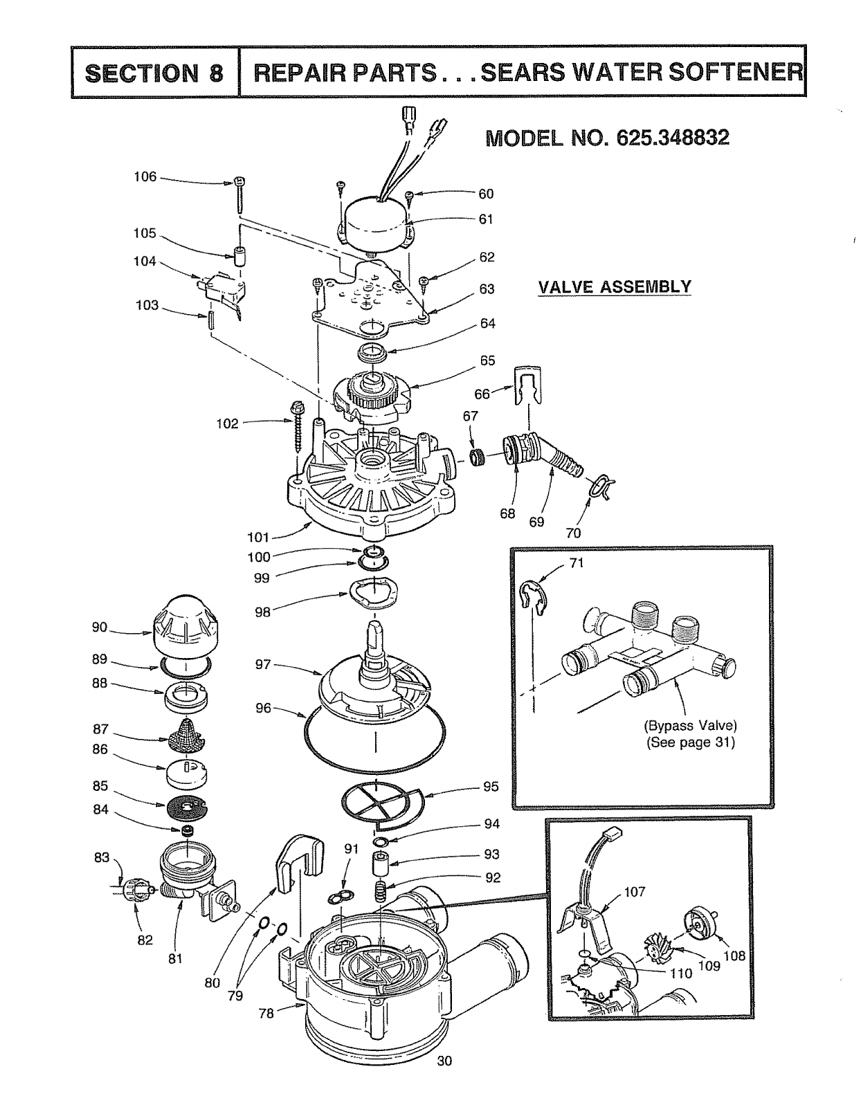
Is cT,o.81 ,,_,,_ ,u illlllllllllll,,lll illll ii ii i n, ii lUUl i iiiii
REPAIR PARTS... SEARS WATER SOFTENER I
....... ==,,i i i ...llml =l Ill '
MODEL NO. 625.348832
tKEY
Noo
6O
61
62
63
64
65
66
67
68
69
70
71
72
73
74
75
76
77
78
79
i 60
61
82
83
84
85
86
87
88
PARTS LIST
PART
NUMBER
900120
7070462
900857
7117808
503288
7113927
7080653
501228
900041
7024160
900431
7t 16713
7082053
900064
7081201
7081104
1202600
7089267
52'1829
7082582
7085166
7090705
7089893
DESCRIPTION
Screw, #6-18 x3/8 (2 req)
Motor
Screw, #6-20 x 3/8 (2 req)
Motor Plate
Bearing
Cam and Gear
Clip (Drain)
Flow Plug
O-Ring, 5/8 x 13/!6
Drain Hose Adaptor
Hose Clamp ®
Clip (2 req.) ®
Valve Body
O-Ring, 1/4 x 3/8 (2 req)
Retainer (Nozzle & Venturi)
Nozzle & Venturi Housing
Nut - Ferrule
Tubing
Flow Plug, ,1 gpm
Gasket
Nozzle and Venturi (Aspirator)
Screen
Screen Support
KEY
NO.
89
90
91
92
93
94
95
96
97
98
99
100
101
102
103
104
105
106
107
108
t09
110
PART
NUMBER
7039068
7081188
7081764
1219600
7092642
7092634
7081756
9001006
7103964
7082087
7064372
706438O
7085263
7074123
7077472
7030713
7117816
7070412
7097171
2204101
4020004
9O00803
7085239
7117117
7092163
DESCRIPTION
O-R_ng,1:3/16x1-_i8 ....
Cap
Seal (Nozzle & Venturi)
Spring
Plug (Drain Seal)
O-Ring 3/8 x 9/16
Rotor Seal
O-Ring, 3-3/8 x 3-5/8
Rotor & Disc
Wave Washer
O-Ring, 3/4 x !5/16
O-Ring, 7/16 x 5/8
Valve Cover
Screw, #10-14 x 2 (5 req,)
Expansion Pin
Switch
Spacer
Screw, #4-24 x 1-1/8 (flat head)
Sensor Housing
Turbine Support and Shaft
Turbine
O-Ring
Nozzle & Venturi Assem. (Incl,
Key No& 81, and 84 through 90)
Small Parts Skin Pack. (Incl, all
parts marked, epg, 28, 29, 31)
Seal Kit (lncl. Key Noso 91, 94,
95, 96, 99 and 100)
_, not illustrated
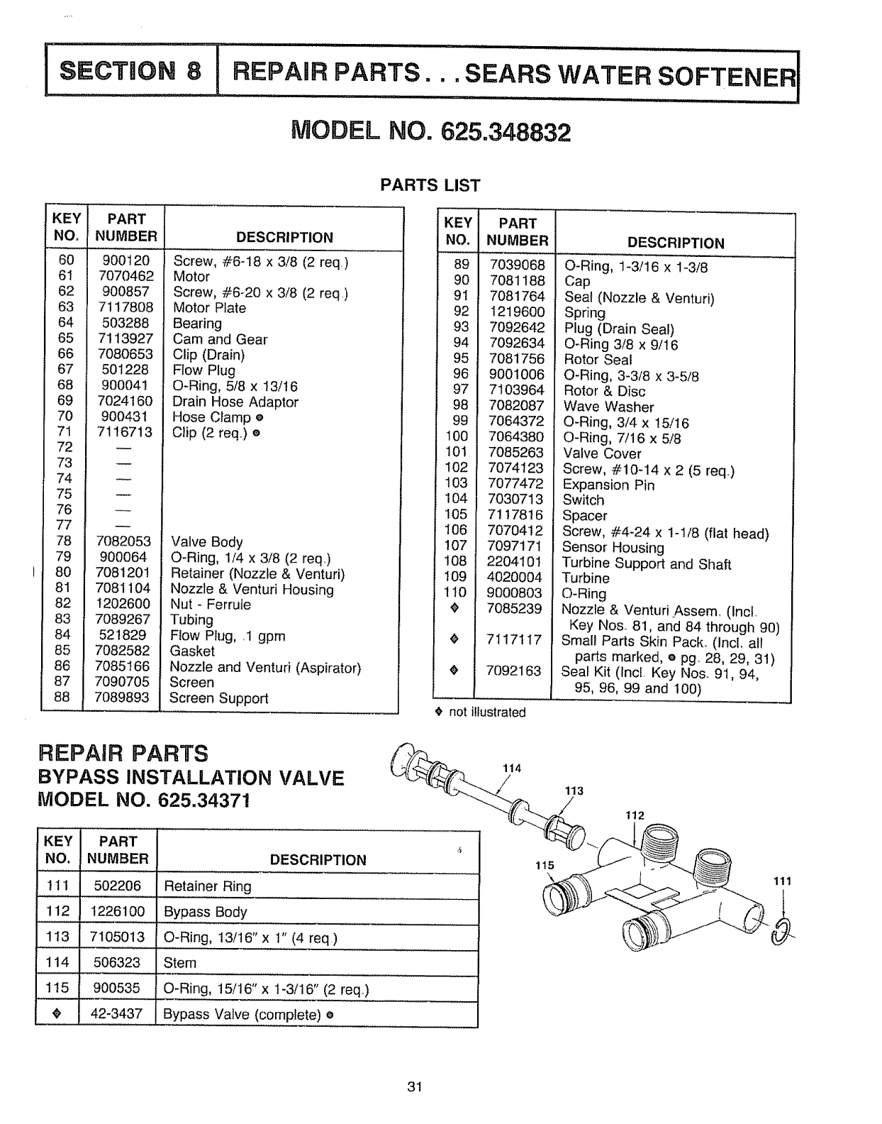
REPAIR PARTS
BYPASS INSTALLATION VALVE
MODEL NO. 625.34371
KEY PART 4
NO. NUMBER DESCRIPTION
1! 1 502206 Retainer Ring
................,,,,,,,,, , .... ,,,,,,,,,
112 1226100 Bypass Body
..... ,,,, ........... ,,
113 7105013 O-Ring, 13/16"x 1" (4 req)
114 506323 Stem
115 900535 O-Ring, 15/16" x t -3/16" (2 req.)
42-3437 Bypass Valve (complete) e
114
/113
/
115
112
111
31
OWNERS
MANUAL
SERVICE
MODEL NO,
625.348832
HOW TO ORDER
REPAIR PARTS
TELL SEARS "YOU
WANT IT INSTALLED
THEN RELAX
....... ,i i i
F642-I 292
Now that you have purchased your water softener, should a need ever
exist for repair parts or' service, simply contact any Sears Service Center_
Be sure to provide al! pertinent facts when you call or visit.
The model number of your water softener' is found on the rating decal.
This decal is on the inside, front of the storage tank rim..
WHEN ORDERING REPAIR PARTS, ALWAYS GIVE THE FOLLOW-
ING INFORMATION:
PART NUMBER
MODEL NUMBER
PART DESCRIPTION
NAME OF ITEM
All parts listed may be ordered from any Sears Service Center_
tf the parts you need are not stocked locally, your order' will be elec-
tronically transmitted to a Sears Repair Parts Distribution center for
handling.
When Sears arranges the installation, you can be sure the job is done
right. We will arrange for professional workmanship ...... and we'll take
care of the entire project° What's more, during installation you get in-
sured protection ..... against property damage and also against accidents
to workmen_ All you have to do is talk to your Sears salesperson or
call you_ nearest Sears store today for detailed information_
Sears, Roebuck and Co., Chicago, iil. 60684 U.S.A.
i ll,ll .......
7117256 {R 1!/921
