Kenmore 625349224 User Manual IRON FILTER Manuals And Guides L0803150
KENMORE Iron Filter Manual L0803150 KENMORE Iron Filter Owner's Manual, KENMORE Iron Filter installation guides
User Manual: Kenmore 625349224 625349224 KENMORE IRON FILTER - Manuals and Guides View the owners manual for your KENMORE IRON FILTER #625349224. Home:Plumbing Parts:Kenmore Parts:Kenmore IRON FILTER Manual
Open the PDF directly: View PDF ![]() .
.
Page Count: 32
_ARS
OWNER'S
MANUAL
MODEL NO.
625.349224
Caution:
Read and Follow
All Safety Rules and
Operating Instructions
Before First Use of
This Product.
If you have questions when
installing, operating or main-
taining your filter, and when
setting the timer, call this
toll-free number...
1-800-426-9345
SAVE THIS MANUAL
Kenmore
Automatic Iron Filter
• Warranty
• Start Up /Setting Timer
• How It Works
• Care Of
• Specifications
• Repair Parts
Sears, Roebuck and Co., Hoffman Estates, IL 60179 USA
PRINTED IN U.S.A.
WARRANTY
I I
SEARS RESIDENTIAL WATER FILTER
FULL ONE YEAR WARRANTY ON FILTER
For one year from the date of purchase, when this water filter is installed and maintained in
accordance with our instructions, Sears will repair, free of charge, defects in materials or
workmanship in this water filter.
FULL FIVE YEAR WARRANTY AGAINST LEAKS
For five years from the date of purchase, Sears will furnish and install a new current model water
filter tank, free of charge, if the tank develops a leak.
TO OBTAIN WARRANTY SERVICE, SIMPLY CONTACT THE NEAREST SEARS SERVICE
CENTER THROUGHOUT THE UNITED STATES. "This warranty applies onlywhile this product
is in use in the United States."
This warranty gives you specific legal rights, and you may have other rights which vary from state
to state.
Sears, Roebuck and Co., D/817 WA, Hoffman Estates, IL 60179
If you want your water filter professionally installed, talk to your Sears Salesman. He will arrange for a prompt,
quality installation by Sears Authorized installers.
SEARS INSTALLATION POLICY
All installation labor arranged by Sears shall be per-
formed in a neat, workmanlike manner in accordance
with generally accepted trade practices. Further, all
installations shall comply with all local laws, codes,
regulations and ordinances. Customer shall also be
protected, during installation, by insurance relating to
Property Damage, Workman's Compensation and
Public Liabilility.
SEARS INSTALLATION WARRANTY
In addition to any warranty extended to you on
the Sears merchandise involved, which warranty
becomes effective the date the merchandise is
installed, should the workmanship of any Sears
arranged installation prove faulty within one year,
Sears will, upon notice from you, cause such faults to
be corrected at no additional cost to you.
FACTS AND FIGURES TO KEEP
Fill in the blanks below and keep this book in
a safe place so you always have these facts.
Water Filter Model No. 1"
Serial Number
Date Installed
Iron Content Parts Per Million
*PH Taste And/Or Odor
Water Pressure Pounds/Square Inch
Water Flow Rate Gallons Per Minute
1"The model number is on the rating decal,
located on the back of the filter top cover.
2
TABLE OF CONTENTS
L ]
PAGE
NO.
SECTION 1 WATER FILTER START UP
A. SAFETY GUIDES 4
B. CHECK LIST OF ALL STEP-BY-STEP GUIDES TO INSTALL 5
C. SANITIZING THE WATER FILTER 6
D. PROGRAM THE TIMER 7-8
E. ADJUSTMENT FOR POTASSIUM PERMANGANATE USE 9
SECTION 2 HOW YOUR WATER FILTER WORKS
A. FACE PLATE TIMER FEATURES 10-11
B. IRON IN WATER/HOW FILTER REMOVES IT 12-13
SECTION 3 CARE OF YOUR FILTER
A. CHANGING THE POTASSIUM PERMANGANATE BOTTLE
B. CLEANING THE NOZZLE & VENTURI
C. KEEP THE FILTER FROM FREEZING
D. HELPFUL HINTS CHECKLIST (SERVICE)
14
15
16
17
SECTION 4 OTHER THINGS TO KNOW
A. DIMENSIONS/SPECIFICATIONS 18
SECTION 5
A. ELECTRICAL CONNECTIONS
B. RECHARGE CYCLE TIMES AND DRAIN FLOW RATES
C. DIAGNOSTICS
D. "QUICK-CHECK" TROUBLESHOOTING
E. ROTARY VALVE SERVICE
F. WATER FLOW THROUGH THE FILTER VALVE
SERVICER'S TECH INFORMATION
19
2O
21
22
23
24-26
SECTION 6 REPAIR PARTS 28-31
3
SECTION 1
I
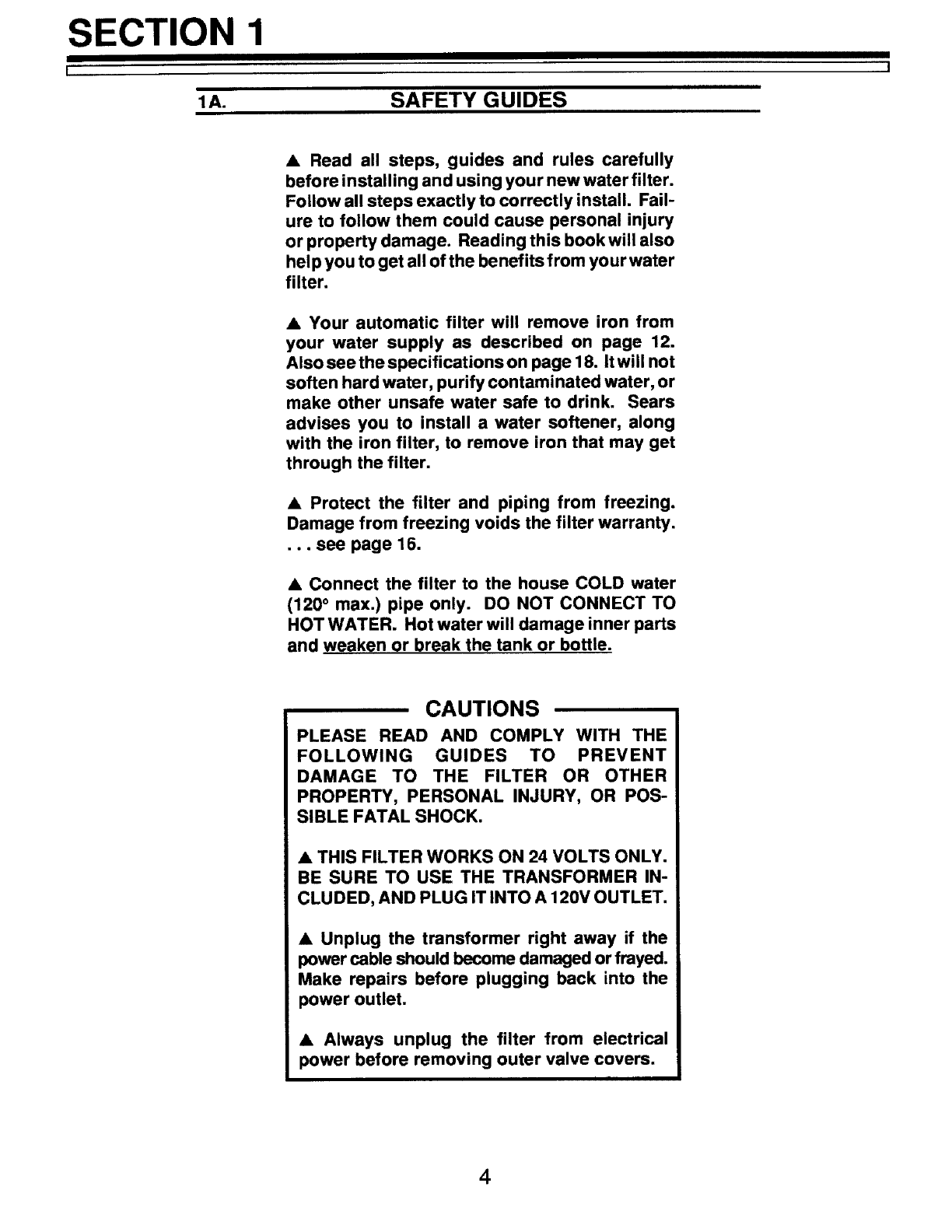
1A. SAFETY GUIDES
•Read all steps, guides and rules carefully
before installing and using your new water filter.
Follow all steps exactly to correctly install. Fail-
ure to follow them could cause personal injury
or property damage. Reading this book will also
help you to get all of the benefits from your water
filter.
•Your automatic filter will remove iron from
your water supply as described on page 12.
Also see the specifications on page 18. It will not
soften hard water, purify contaminated water, or
make other unsafe water safe to drink. Sears
advises you to install a water softener, along
with the iron filter, to remove iron that may get
through the filter.
•Protect the filter and piping from freezing.
Damage from freezing voids the filter warranty.
•.. see page 16.
•Connect the filter to the house COLD water
(120 ° max.) pipe only. DO NOT CONNECT TO
HOT WATER. Hot water will damage inner parts
and weaken or break the tank or bottle.
CAUTIONS
PLEASE READ AND COMPLY WITH THE
FOLLOWING GUIDES TO PREVENT
DAMAGE TO THE FILTER OR OTHER
PROPERTY, PERSONAL INJURY, OR POS-
SIBLE FATAL SHOCK.
•THIS FILTER WORKS ON 24 VOLTS ONLY.
BE SURE TO USE THE TRANSFORMER IN-
CLUDED, AND PLUG IT INTO A 120V OUTLET.
•Unplug the transformer right away if the
power cable should become damaged or frayed.
Make repairs before plugging back into the
power outlet.
•Always unplug the filter from electrical
power before removing outer valve covers.
4
SECTION 1 WATERFILTERSTART-UP
I I
lB. CHECK LIST OF ALL STEP BY STEP GUIDES TO INSTALL
Refer to the Installation Manual, part no. 7146611,
for step-by-step guides.
To be sure you have done all the steps to install the
filter, read the following list. Page numbers referred
to are in the Installation Manual.
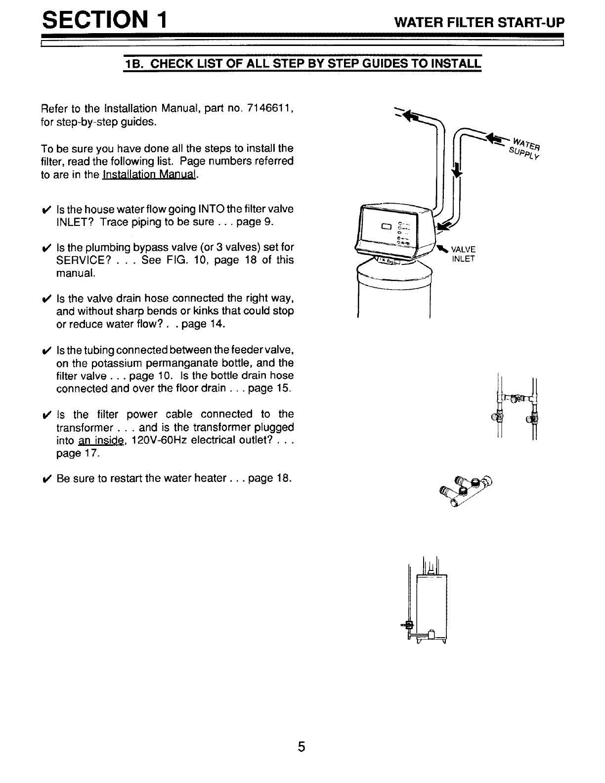
v' Is the house water flow going INTO the filter valve
INLET? Trace piping to be sure.., page 9.
v' Is the plumbing bypass valve (or 3 valves) set for
SERVICE? . . . See FIG. 10, page 18 of this
manual.
i! Is the valve drain hose connected the right way,
and without sharp bends or kinks that could stop
or reduce water flow?., page 14.
v' Is the tubing connected between the feeder valve,
on the potassium permanganate bottle, and the
filter valve.., page 10. Is the bottle drain hose
connected and over the floor drain.., page 15.
V' Is the filter power cable connected to the
transformer.., and is the transformer plugged
into an inside, 120V-60Hz electrical outlet?...
page 17.
I,,' Be sure to restart the water heater.., page 18.
VALVE
INLET
5
SECTION 1 WATERFILTERSTART-UP
I
10. SANITIZING THE WATER FILTER
Care is taken at the factory to keep your water filter
clean and sanitary. Materials used to make the filter
will not infect or contaminate your water supply, and
will not cause bacteria to form or grow. However,
during shipping, storage, installing and operating,
bacteria could get into the filter. For this reason,
sanitizing as follows is suggestedQ when installing.
=
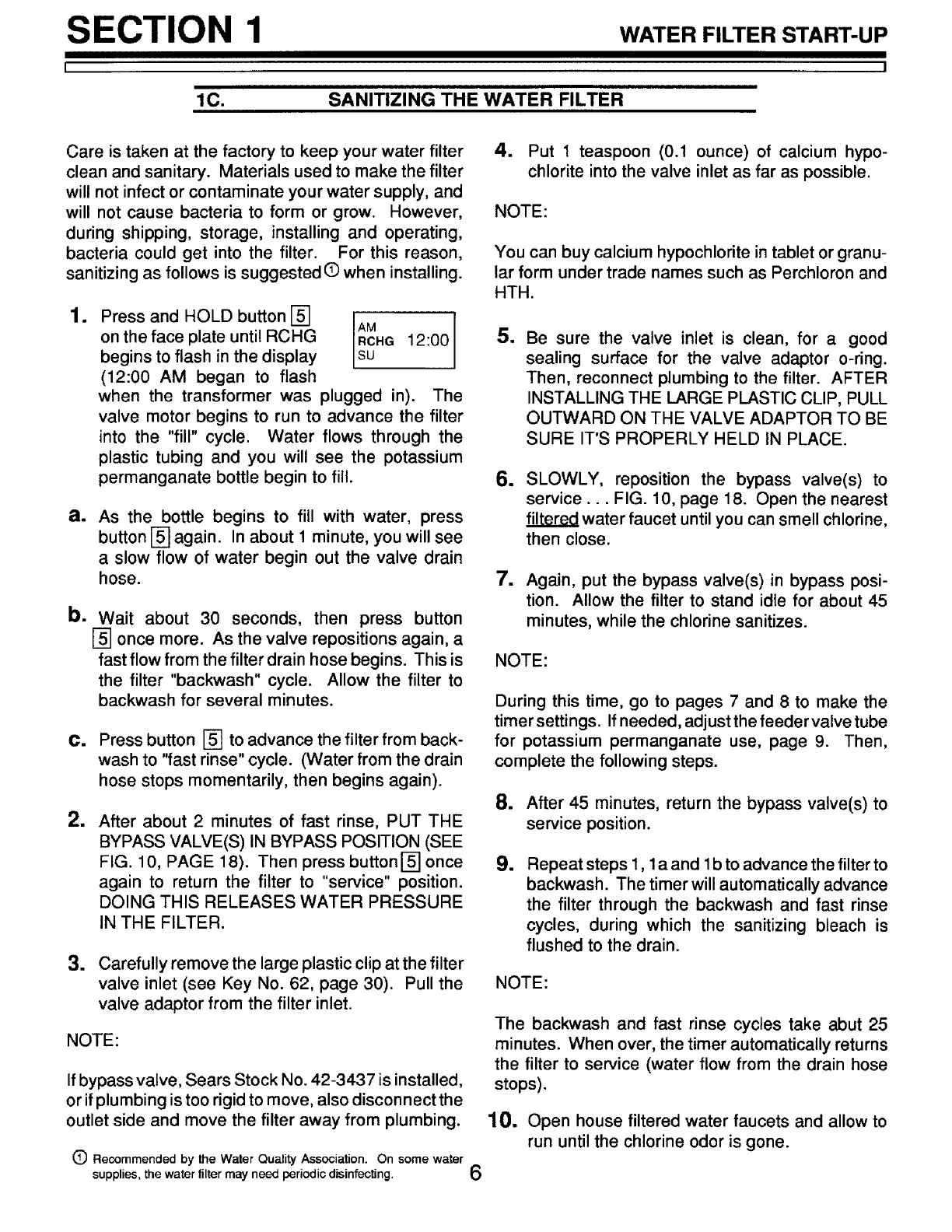
Press and HOLD button [] ARMHG
on the face plate until RCHG 12:00
begins to flash in the display su
(12:00 AM began to flash
when the transformer was plugged in). The
valve motor begins to run to advance the filter
into the "fill" cycle. Water flows through the
plastic tubing and you will see the potassium
permanganate bottle begin to fill.
a= As the bottle begins to fill with water, press
button [] again. In about 1 minute, you will see
a slow flow of water begin out the valve drain
hose.
b= Wait about 30 seconds, then press button
[] once more. As the valve repositions again, a
fast flow from the filter drain hose begins. This is
the filter "backwash" cycle. Allow the filter to
backwash for several minutes.
C=
=
Press button [] to advance the filter from back-
wash to "fast rinse" cycle. (Water from the drain
hose stops momentarily, then begins again).
After about 2 minutes of fast rinse, PUT THE
BYPASS VALVE(S) IN BYPASS POSITION (SEE
FIG. 10, PAGE 18). Then press button[] once
again to return the filter to "service" position.
DOING THIS RELEASES WATER PRESSURE
IN THE FILTER.
3. Carefully remove the large plastic clip at the filter
valve inlet (see Key No. 62, page 30). Pull the
valve adaptor from the filter inlet.
NOTE:
If bypass valve, Sears Stock No. 42-3437 is installed,
or if plumbing is too rigid to move, also disconnect the
outlet side and move the filter away from plumbing.
(_ Recommended by the Water Quality Association. On some water
supplies, the water filter may need periodic disinfecting. 6
4. Put 1 teaspoon (0.1 ounce) of calcium hypo-
chlorite into the valve inlet as far as possible.
NOTE:
You can buy calcium hypochlorite in tablet or granu-
lar form under trade names such as Perchloron and
HTH.
1Be sure the valve inlet is clean, for a good
sealing surface for the valve adaptor o-ring.
Then, reconnect plumbing to the filter. AFTER
INSTALLING THE LARGE PLASTIC CLIP, PULL
OUTWARD ON THE VALVE ADAPTOR TO BE
SURE IT'S PROPERLY HELD IN PLACE.
=SLOWLY, reposition the bypass valve(s) to
service... FIG. 10, page 18. Open the nearest
_water faucet until you can smell chlorine,
then close.
7. Again, put the bypass valve(s) in bypass posi-
tion. Allow the filter to stand idle for about 45
minutes, while the chlorine sanitizes.
NOTE:
During this time, go to pages 7 and 8 to make the
timersettings. If needed, adjust the feeder valve tube
for potassium permanganate use, page 9. Then,
complete the following steps.
8. After 45 minutes, return the bypass valve(s) to
service position.
=Repeat steps 1,1 a and 1b to advance the filter to
backwash. The timer will automatically advance
the filter through the backwash and fast rinse
cycles, during which the sanitizing bleach is
flushed to the drain.
NOTE:
The backwash and fast rinse cycles take abut 25
minutes. When over, the timer automatically returns
the filter to service (water flow from the drain hose
stops).
10. Open house filtered water faucets and allow to
run until the chlorine odor is gone.
SECTION 1 WATER FILTER START-UP
1D, PROGRAM THE TIMER
J
/
display
GPRESENT _ME AND DAY
RECHARGE _ME
RECHARGE DAY
SET/CLEAR
/@ ON/OFF VACATION
HOLD RECHARGE NOW
buttons
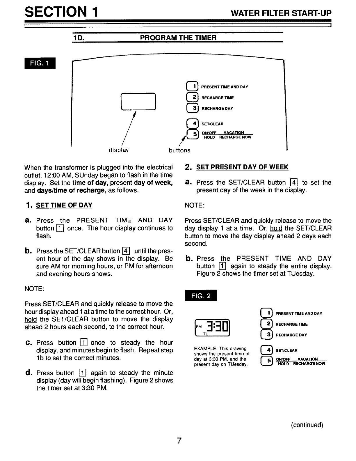
When the transformer is plugged into the electrical
outlet, 12:00 AM, SUnday began to flash in the time
display. Set the time of day, present day of week,
and daysltime of recharge, as follows.
1. SET TIME OF DAY
a. Press the PRESENT TIME AND DAY
button [] once. The hour display continues to
flash.
b= Press the SET/CLEAR button [] until the pres-
ent hour of the day shows in the display. Be
sure AM for morning hours, or PM for afternoon
and evening hours shows.
NOTE:
Press SET/CLEAR and quickly release to move the
hour display ahead 1at atime to the correct hour. Or,
the SET/CLEAR button to move the display
ahead 2 hours each second, to the correct hour.
¢. Press button [] once to steady the hour
display, and minutes begin to flash. Repeat step
lb to set the correct minutes.
d. Press button [] again to steady the minute
display (day will begin flashing). Figure 2 shows
the timer set at 3:30 PM.
2. SET PRESENT DAY OF WEEK
a. Press the SET/CLEAR button [] to set the
present day of the week in the display.
NOTE:
Press SET/CLEAR and quickly release to move the
day display 1 at a time. Or, hold the SET/CLEAR
button to move the day display ahead 2 days each
second.
b. Press the PRESENT TIME AND DAY
button [] again to steady the entire display.
Figure 2 shows the timer set at TUesday.
3PRESENT TIME AND DAY
[PM TU_:3D ] _ :E[:::RF:: T:::
EXAMPLE: This drawing
shows the present time of
day at 3:30 PM, and the
present day on TUesday.
_SET/CLEAR
ON/OFF VA_AT!ON
HOLD RECHARGE NOW
(continued)
7
SECTION 1
I
1D. PROGRAM THE TIMER
WATER FILTER START-UP
I
3. SET DAYS OF RECHARGE
IF YOU HAVE A WATER SOFTENER OR
OTHER AUTOMATIC FILTER... A good
water flow rate is needed for proper recharging
and/or backwashing of all water conditioners.
To help assure good water flow, you should
offset the timers on each conditioner so
recharges do not occur on the same days, or at
the same time as follows.
••. Most Sears water softeners are factory set (many
are adjustable) to recharge from 2:00 to
4:00 am.
• .. Sears Automatic Iron Filter is factory set to
recharge from 12:00 AM to about 1:50 AM.
• • • Other Sears filters (Clarifier, Neutralizer, Taste &
Odor) are factory set to backwash from 12:00
AM to about 12:40 AM.
• --Offset the timers on all equipment to
recharges or backwashes at 12:00, 2:00 and
4:00 AM, or 1:00, 3:00 and 5:00 AM, etc.
a. Look at the "Suggested Recharge Days" table.
The table shows you the days to set the iron filter
for recharge, depending on your household needs.
b= Press the RECHARGE DAY BUTTON [] AND
SUnday begins to flash•
If you want recharges on Sunday (from table),
press the SET/CLEAR button [] to display ON.
C=
If you do not want Sunday recharges, press
button [] to display OFF.
Press button [] again to display a flashing
MOnda_ As you did in step b above, press
buttonl4 Jtodisplay ON for recharge on Monday,
or OFF for no recharge on Monday•
d. Press button [_ for every day of the week, each
time using button[]to display ON (for recharge)
or OFF (no recharge) as needed.
e=
=
After setting ON or OFF for Saturday, press
button [] to return the present time in the
display.
SET TIME OF RECHARGE
The filter is factory set to begin recharge at 12:00
AM, ending at about 1:50 AM. If a different
recharge time is desired, or needed, do the
following.
a. Press the RECHARGE TIME button _]once, to
display a flashing 12:00 AM, the factory setting.
b. Press the SET/CLEAR button [] until the
desired recharge starting time shows in the
display.
NOTE: Press button [] and quickly release to move
the display ahead 1 hour at a time. Or, hok:l buttonl-_
to move the display ahead 2 hours each second•
C. Press button [] to return the present time.
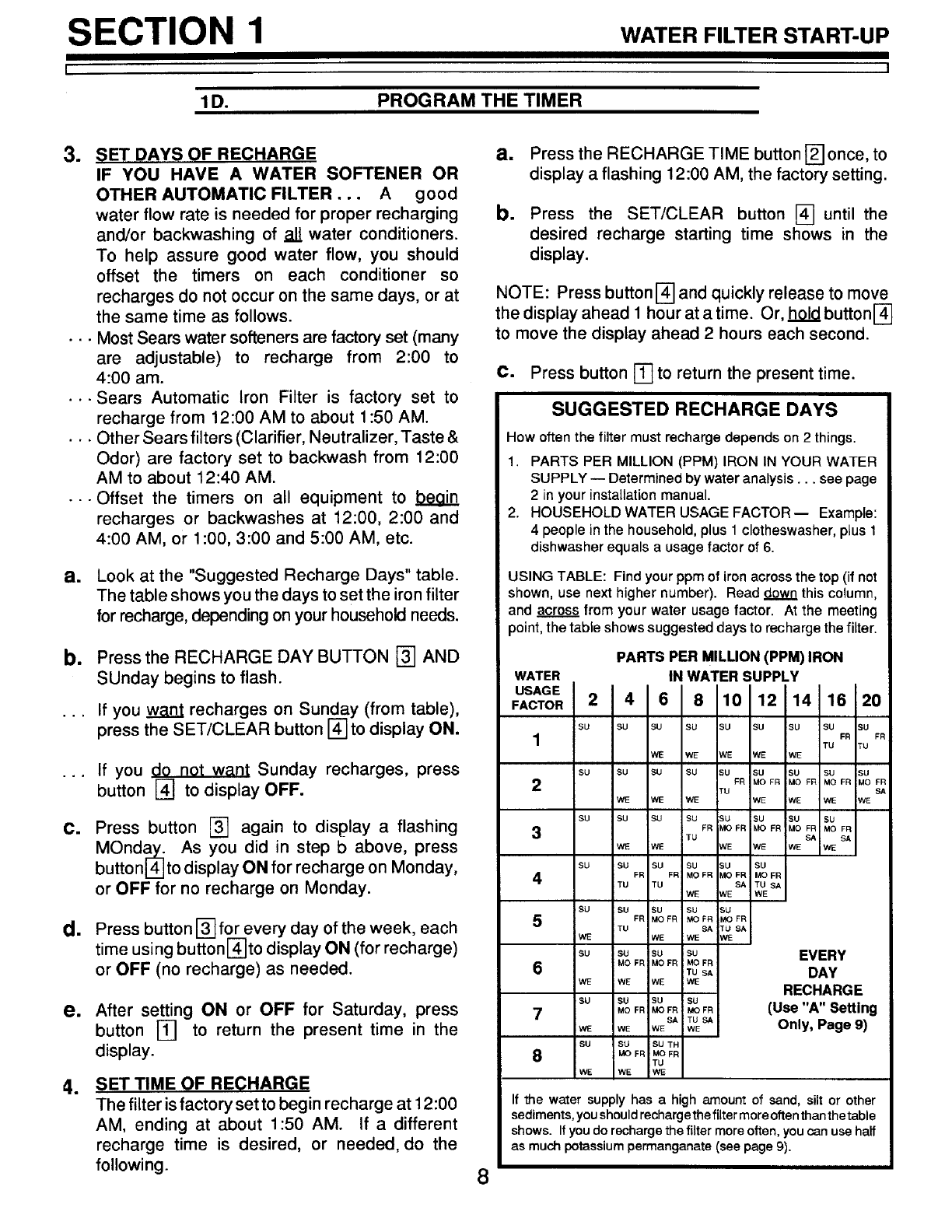
SUGGESTED RECHARGE DAYS
How often the filter must recharge depends on 2 things.
1. PARTS PER MILLION (PPM) IRON IN YOUR WATER
SUPPLY -- Determined by water analysis•., see page
2 in your installation manual.
2. HOUSEHOLD WATER USAGE FACTOR-- Example:
4 people in the household, plus 1 clotheswasher, plus 1
dishwasher equals a usage factor of 6.
USING TABLE: Find your ppm of iron across the top (if not
shown, use next higher number). Read down this column,
and across from your water usage factor. At the meeting
point, the table shows suggested days to recharge the filter.
PARTS PER MILLION (PPM) IRON
WATER IN WATER SUPPLY
USAGE I 10112114
FACTOR 2 4 6 I 8 16 20
$U $U SU SO _U SU SO $U SO
FR FR
1 ,u ,o
WE WE NE WE WE
SU SU SU SU _U SU SU SU SU
FR MO FR MO FR MO FR MO FR
r'u SA
WE WE WE WE ME WE WE
SU SU SU SU _U $U SU SU
FR VtO FR MO FR MO FR MO FR
TU SA SA
WE NE WE WE WE
SU SU SU SU _U SU
FR FR MO FR _ FR MO FR
4TU TU SA I TU SA
WE NE WE
SU SU SU SU _U
FR MO FR MO FR k#,OFR
TU SA rU SA
WE WE WE
su su su su EVERY
MO FR MO FR MO FR
"rusA DAY
WE WE WE WE RECHARGE
SU SU SU SU
7.o FR MO FR MO FR (Use "A" Setting
SA TU SA
WE wE wE wE Only, Page 9)
SU SLI SU TH
MO FR MO FR
TU
WE WE
If the water supply has a high amount of sand, silt or other
sediments, you should rechargethefiltermoreoftenthanthetable
shows. If you do recharge the filter more often, you can use half
as much potassium permanganate (see page g).
8
SECTION 1 WATER FILTER START-UP
I I
1E. ADJUSTMENT FOR POTASSIUM PERMANGANATE USE
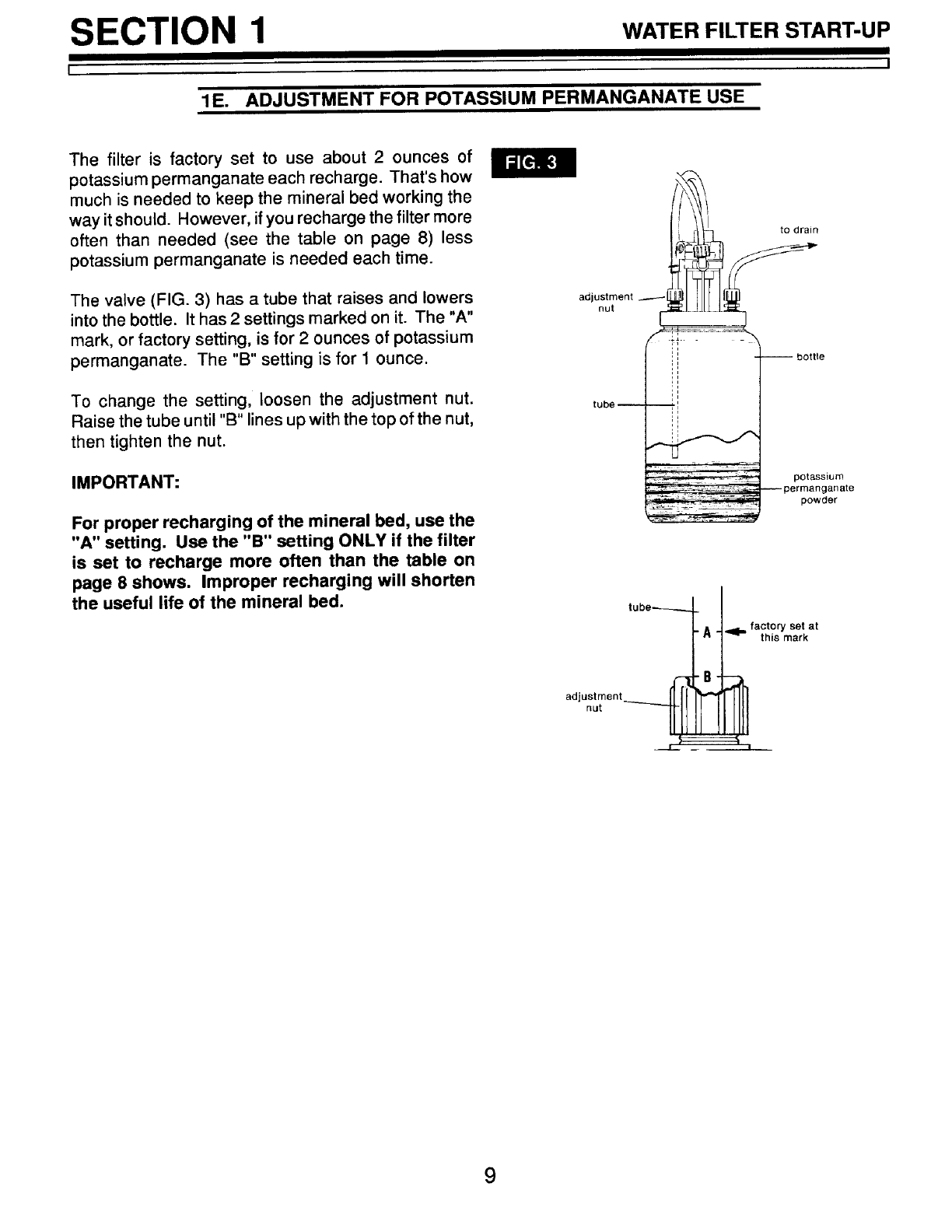
The filter is factory set to use about 2 ounces of
potassium permanganate each recharge. That's how
much is needed to keep the mineral bed working the
way it should. However, if you recharge the filter more
often than needed (see the table on page 8) less
potassium permanganate is needed each time.
The valve (FIG. 3) has a tube that raises and lowers
into the bottle. It has 2 settings marked on it. The "A"
mark, or factory setting, is for 2 ounces of potassium
permanganate. The "B" setting is for 1 ounce.
To change the setting, loosen the adjustment nut.
Raise the tube until "B" lines up with the top of the nut,
then tighten the nut.
IMPORTANT:
For proper recharging of the mineral bed, use the
"A" setting. Use the "B" setting ONLY if the filter
is set to recharge more often than the table on
page 8 shows. Improper recharging will shorten
the useful life of the mineral bed.
adjustment
nut
:I
tube-- -_,,
tube_..._
adjustment _nut
to drain
-- bottle
potassium
--permanganate
powder
,,,_lfactoryset at
this mark
9
SECTION 2 NowYourwATERFILTERWORKS
2A.
I
FACE PLATE TIMER FEATURES
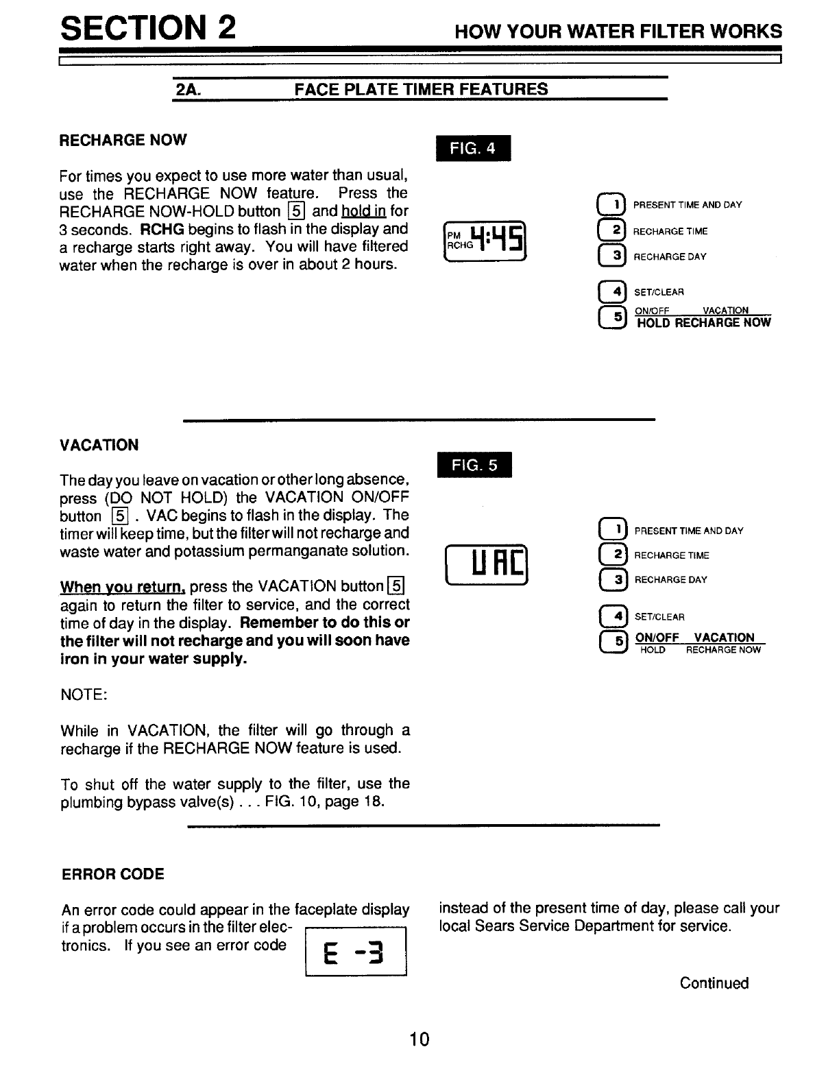
RECHARGE NOW
For times you expect to use more water than usual,
use the RECHARGE NOW feature. Press the
RECHARGE NOW-HOLD button [] and _ for
3 seconds. RCHG begins to flash in the display and
a recharge starts right away. You will have filtered
water when the recharge is over in about 2 hours.
QPRESENT TIME AND DAY
(_ RECHARGE TIME
_) RECHARGE DAY
SET/CLEAR
3 ON,OFF VACATION
HOLD RECHARGE NOW
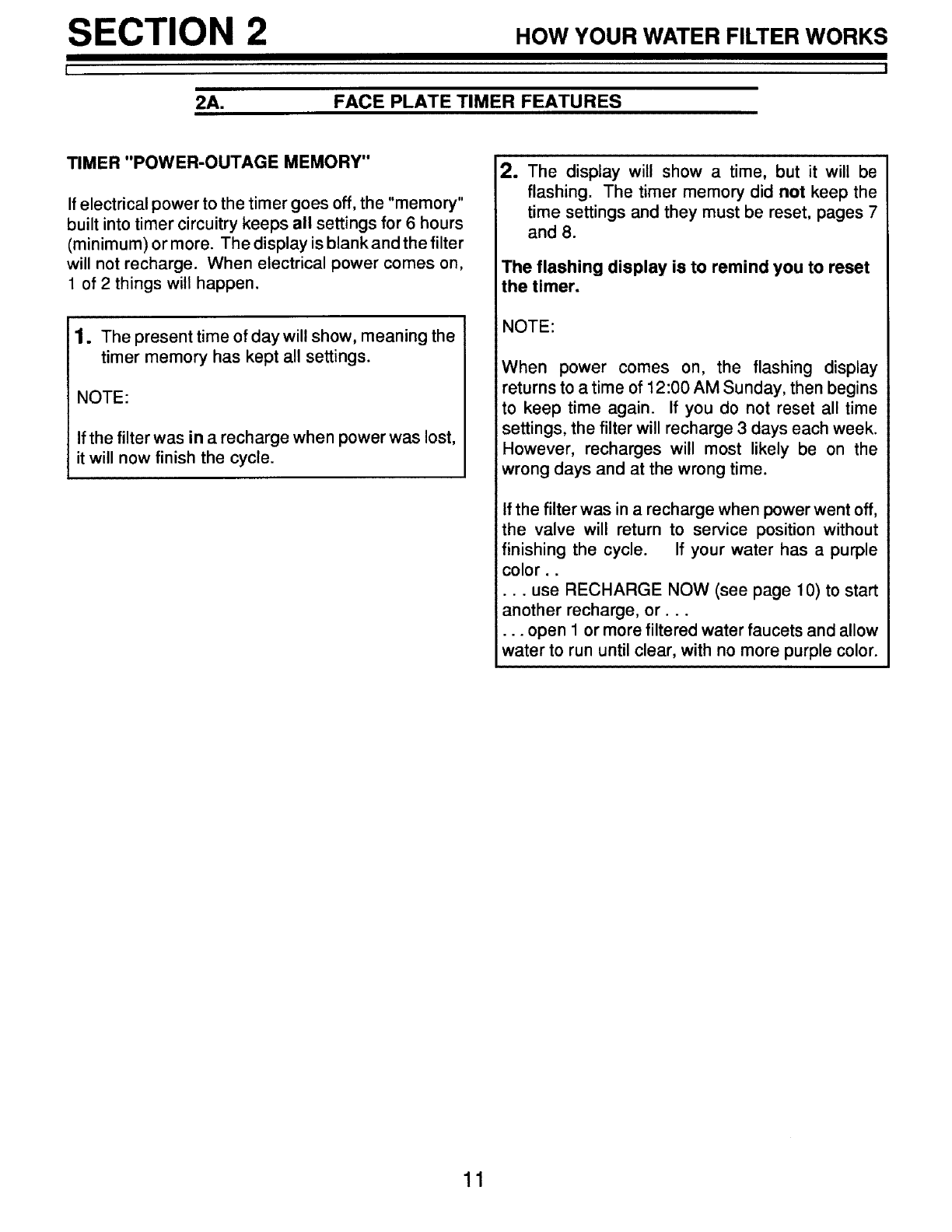
VACATION
The day you leave on vacation or other long absence,
press (DO NOT HOLD) the VACATION ON/OFF
button 15[ . VAC begins to flash in the display. The
timer will keep time, but the filter will not recharge and
waste water and potassium permanganate solution.
When you return, press the VACATION button []
again to return the filter to service, and the correct
time of day in the display. Remember to do this or
the filter will not recharge and you will soon have
iron in your water supply.
NOTE:
While in VACATION, the filter will go through a
recharge if the RECHARGE NOW feature is used.
To shut off the water supply to the filter, use the
plumbing bypass valve(s)... FIG. 10, page 18.
Q PRESENT TIME AND DAY
_ RECHARGETIME
C_ RECHARGEDAY
_ SETICLEAR
_ON/OFF VACATION
HOLD RECHARGE NOW
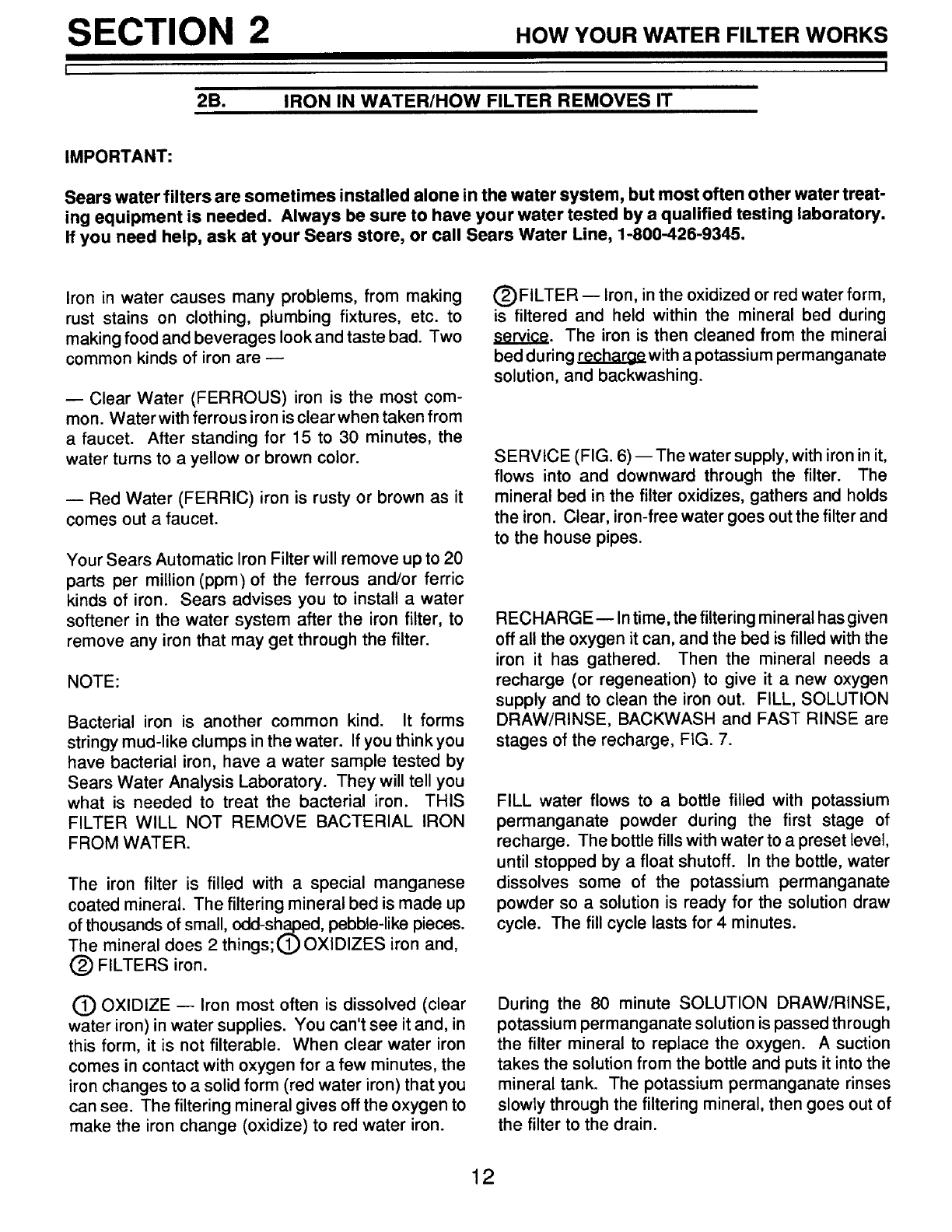
ERROR CODE
An error code could appear in the faceplate display
if a problem occurs in the filter elec-
tronics. If you see an error code E "-3
instead of the present time of day, please call your
local Sears Service Department for service.
Continued
10
SECTION 2 HowYOURWATERFILTERWORKS
I
2A. FACE PLATE TIMER FEATURES
TIMER "POWER-OUTAGE MEMORY"
If electrical power to the timer goes off, the "memory"
built into timer circuitry keeps all settings for 6 hours
(minimum) or more. The display is blank and the filter
will not recharge. When electrical power comes on,
1 of 2 things will happen.
1. The present time of day will show, meaning the
timer memory has kept all settings.
NOTE:
If the filter was in a recharge when power was lost,
it will now finish the cycle•
2. The display will show a time, but it will be
flashing. The timer memory did not keep the
time settings and they must be reset, pages 7
and 8•
The flashing display is to remind you to reset
the timer.
NOTE:
When power comes on, the flashing display
returns to a time of 12:00 AM Sunday, then begins
to keep time again• If you do not reset all time
settings, the filter will recharge 3 days each week.
However, recharges will most likely be on the
wrong days and at the wrong time.
If the filter was in a recharge when power went off,
the valve will return to service position without
finishing the cycle• If your water has a purple
color..
•. use RECHARGE NOW (see page 10) to start
another recharge, or...
•. open 1 or more filtered water faucets and allow
water to run until clear, with no more purple color.
11
SECTION 2 HOWYOURWATERFILTERWORKS
2B.
1
IRON IN WATER/HOW FILTER REMOVES IT
IMPORTANT:
Sears water filters are sometimes installed alone in the water system, but most often other water treat-
ing equipment is needed. Always be sure to have your water tested by a qualified testing laboratory.
If you need help, ask at your Sears store, or call Sears Water Line, 1-800-426-9345.
Iron in water causes many problems, from making
rust stains on clothing, plumbing fixtures, etc. to
making food and beverages look and taste bad. Two
common kinds of iron are --
-- Clear Water (FERROUS) iron is the most com-
mon. Water with ferrous iron is clear when taken from
afaucet. After standing for 15 to 30 minutes, the
water turns to a yellow or brown color.
-- Red Water (FERRIC) iron is rusty or brown as it
comes out a faucet.
Your Sears Automatic Iron Filter will remove up to 20
parts per million (ppm)of the ferrous and/or ferric
kinds of iron. Sears advises you to install a water
softener in the water system after the iron filter, to
remove any iron that may get through the filter.
NOTE:
Bacterial iron is another common kind. It forms
stringy mud-like clumps in the water. If you think you
have bacterial iron, have a water sample tested by
Sears Water Analysis Laboratory. They will tell you
what is needed to treat the bacterial iron. THIS
FILTER WILL NOT REMOVE BACTERIAL IRON
FROM WATER.
The iron filter is filled with a special manganese
coated mineral. The filtering mineral bed is made up
of thousands of small, odd-sh .aped, pebble-like pieces.
The mineral does 2 things; 1_ OXIDIZES iron and,
(_ FILTERS iron.
(_ OXIDIZE -- Iron most often is dissolved (clear
water iron) in water supplies. You can't see it and, in
this form, it is not filterable. When clear water iron
comes in contact with oxygen for a few minutes, the
iron changes to a solid form (red water iron) that you
can see. The filtering mineral gives off the oxygen to
make the iron change (oxidize) to red water iron.
(_FILTER -- Iron, in the oxidized or red water form,
is filtered and held within the mineral bed during
service. The iron is then cleaned from the mineral
bed during recharge with a potassium permanganate
solution, and backwashing.
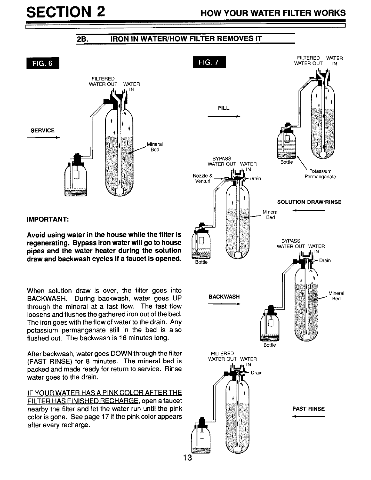
SERVICE (FIG. 6) -- The water supply, with iron in it,
flows into and downward through the filter. The
mineral bed in the filter oxidizes, gathers and holds
the iron. Clear, iron-free water goes out the filter and
to the house pipes.
RECHARGE-- In time, the filtering mineral has given
off all the oxygen it can, and the bed is filled with the
iron it has gathered. Then the mineral needs a
recharge (or regeneation) to give it a new oxygen
supply and to clean the iron out. FILL, SOLUTION
DRAW/RINSE, BACKWASH and FAST RINSE are
stages of the recharge, FIG. 7.
FILL water flows to a bottle filled with potassium
permanganate powder during the first stage of
recharge. The bottle fills with water to a preset level,
until stopped by a float shutoff. In the bottle, water
dissolves some of the potassium permanganate
powder so a solution is ready for the solution draw
cycle. The fill cycle lasts for 4 minutes.
During the 80 minute SOLUTION DRAW/RINSE,
potassium permanganate solution is passed through
the filter mineral to replace the oxygen. A suction
takes the solution from the bottle and puts it into the
mineral tank. The potassium permanganate rinses
slowly through the filtering mineral, then goes out of
the filter to the drain.
12
SECTION 2 MowYourwATERFILTERWORKS
I
2B.
I
IRON IN WATER/HOW FILTER REMOVES IT
FILTERED WATER
WATER OUT IN
SERVICE
FILTERED
WATER OUT WATER
IN
Mineral
Bed
IMPORTANT:
Avoid using water in the house while the filter is
regenerating. Bypass iron water will go to house
pipes and the water heater during the solution
draw and backwash cycles if a faucet is opened.
When solution draw is over, the filter goes into
BACKWASH. During backwash, water goes UP
through the mineral at a fast flow. The fast flow
loosens and flushes the gathered iron out of the bed.
The iron goes with the flow of water to the drain. Any
potassium permanganate still in the bed is also
flushed out. The backwash is 16 minutes long.
After backwash, water goes DOWN through the filter
(FAST RINSE) for 8 minutes. The mineral bed is
packed and made ready for return to service. Rinse
water goes to the drain.
IF YOUR WATER HAS A PINK COLOR AFTER THE
FILTER HAS FINISHED RECHARGE, open a faucet
nearby the filter and let the water run until the pink
color is gone. See page 17 if the pink color appears
after every recharge,
FILL
BYPASS
WATER OUT WATER
IN
Nozzle &
Venturi _
ff
iii: i!
Bottle
BACKWASH
FILTERED
WATER OUT WATER
IN
13
Bottle _ Potassium
Permanganate
SOLUTION DRAW/RINSE
Mineral '_
Bed
BYPASS
WATER OUT WATER
IN
Bottle
Mineral
Bed
FAST RINSE
ii
SECTION 3 CARE OF YOUR FILTER
I I
3A. CHANGING THE POTASSIUM PERMANGANATE BOTTLE
HOW LONG DOES A BO'I-rLE OF POTASSIUM
PERMANGANATE LAST? How long a bottle lasts
depends on how often the filter regnerates and how
much potassium permanganate is used (pages 8 and
9). You can use the chart below as aguide to tell you
about how long it will last.
HOW LONG THE POTASSIUM
PERMANGANTE BOTTLE LASTS
No. of Recharges
Each Week
1
2
3
4
5
6
7
Tube Set
at "A" Mark
9 months
41/2 months
3 months
9weeks
7 weeks
6 weeks
5 weeks
Tube Set
At "B" Mark
18 months
9 months
6months
4 1/2 months
3 1/2 months
3 months
2 1/2 months
IT IS IMPORTANT that you change the bottle before
all the potassium permanganate is gone. If the filter
goes too long without a regeneration with potassium
permanganate, the filtering mineral will lose its man-
ganese coating and you can't replace it. New mineral
and the service call to change it are costly. You can
buy replacement bottles from Sears, Stock No. 42-
34417.
WARNING:
HANDLE THE BOTTLE WITH CARE. POTASSIUM
PERMANGANATE STAINS DEEPLY. DO NOT
GET IT ON YOUR CLOTHES OR YOUR SKIN,
YOU SHOULD WEAR OLD CLOTHES WHEN
CHANGING THE BOTTLE. PLEASE READ THE
WARNINGS PRINTED ON THE BOTTLE.
BULK POTASSIUM PERMANGANATE POWDER:
If purchased and used in bulk form, DO NOT OVER-
FILLTHE BOTTLE. Fill with only 6 Ibs. of powder (see
note below). Too much powder will stop or restrict
solution flow from the bottle. Before filling, be sure to
thoroughly clean the bottle.
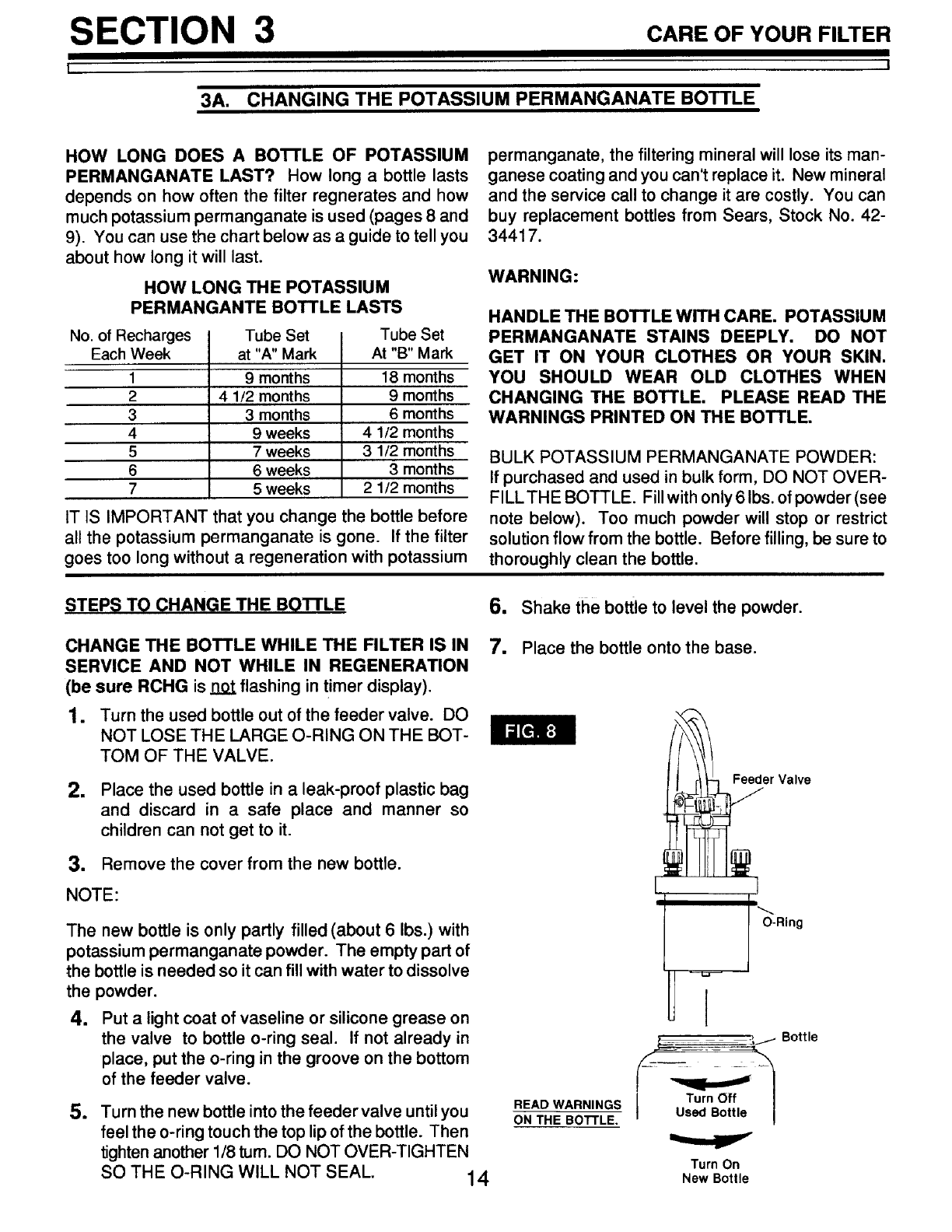
STEPS TO CHANGE THE BOTTLE
CHANGE THE BOTTLE WHILE THE FILTER IS IN
SERVICE AND NOT WHILE IN REGENERATION
(be sure RCHG is not flashing in timer display).
1. Turn the used bottle out of the feeder valve. DO
NOT LOSE THE LARGE O-RING ON THE BOT-
TOM OF THE VALVE.
2. Place the used bottle in a leak-proof plastic bag
and discard in a safe place and manner so
children can not get to it.
3, Remove the cover from the new bottle.
NOTE:
The new bottle is only partly filled (about 6 Ibs.) with
potassium permanganate powder. The empty part of
the bottle is needed so it can fill with water to dissolve
the powder.
4. Put a light coat of vaseline or silicone grease on
the valve to bottle o-ring seal. If not already in
place, put the o-ring in the groove on the bottom
of the feeder valve.
mTurn the new bottle into the feeder valve until you
feel the o-ring touch the top lip of the bottle. Then
tighten another 1/8 turn. DO NOT OVER-TIGHTEN
SO THE O-RING WILL NOT SEAL. 14
6. Shake the bottle to level the powder.
7. Place the bottle onto the base.
Feeder Valve
O-Ring
READ WARNINGS
ON THE BOTTLE.
T1_Bottle
I Used Bottle |
Turn On
New Bottle
SECTION 3 CARE OF YOUR FILTER
I
3B. CLEANING THE NOZZLE AND VENTURI
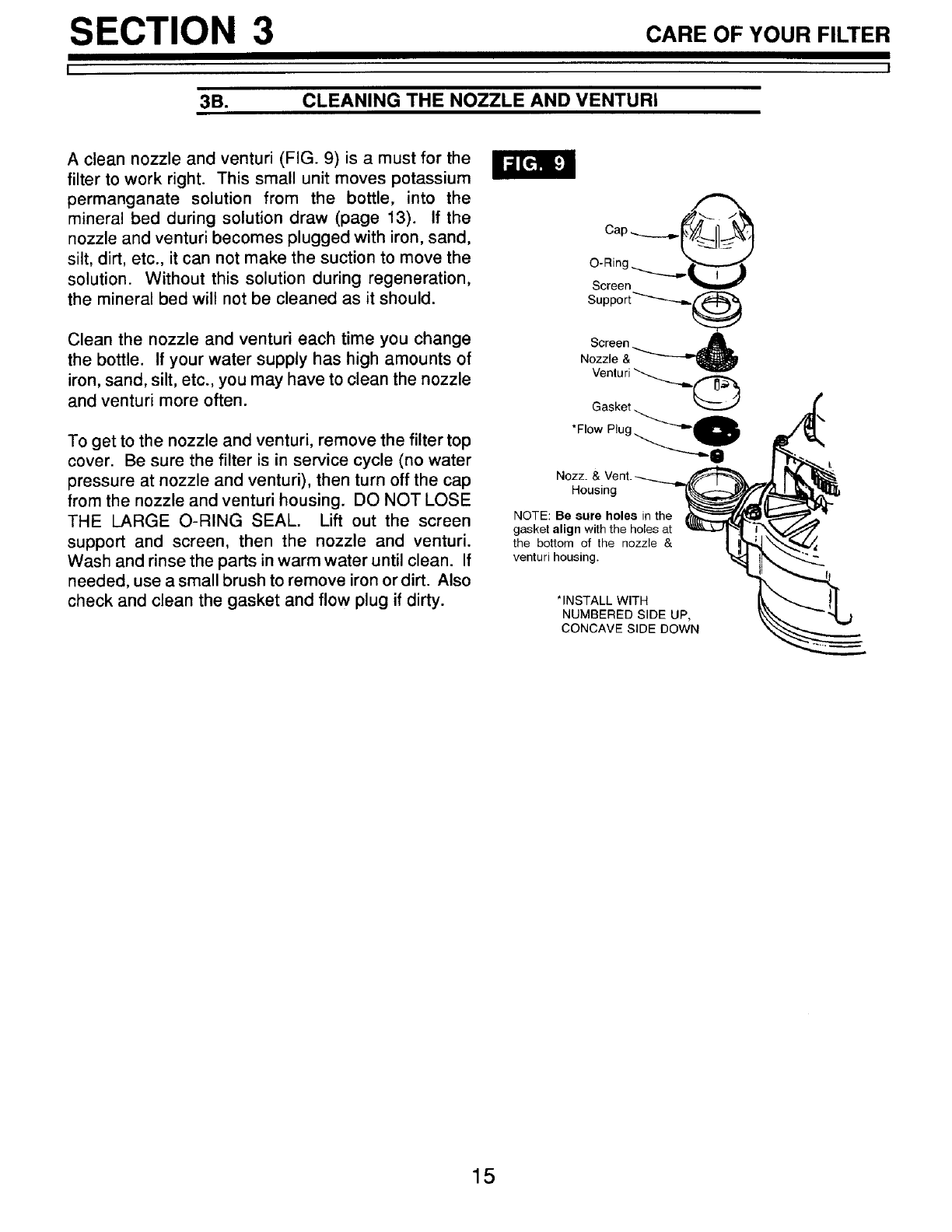
A clean nozzle and venturi (FIG. 9) is a must for the
filter to work right. This small unit moves potassium
permanganate solution from the bottle, into the
mineral bed during solution draw (page 13). If the
nozzle and venturi becomes plugged with iron, sand,
silt, dirt, etc., it can not make the suction to move the
solution. Without this solution during regeneration,
the mineral bed wilt not be cleaned as it should.
Clean the nozzle and venturi each time you change
the bottle. If your water supply has high amounts of
iron, sand, silt, etc., you may have to clean the nozzle
and venturi more often.
To get to the nozzle and venturi, remove the filter top
cover. Be sure the filter is in service cycle (no water
pressure at nozzle and venturi), then turn off the cap
from the nozzle and venturi housing. DO NOT LOSE
THE LARGE O-RING SEAL. Lift out the screen
support and screen, then the nozzle and venturi.
Wash and rinse the parts in warm water until clean. If
needed, use a small brush to remove iron or dirt. Also
check and clean the gasket and flow plug if dirty.
Cap _ __
O-Ring _.._.__ _._
Screen
Nozz.
Housing
NOTE: Be sure holes in the
gasket align with the holes at
the bottom of the nozzle &
venturi housing.
* INSTALL WITH
NUMBERED SIDE UP,
CONCAVE SIDE DOWN
15
SECTION 3 CAREOFYOURFILTER
I I
30. KEEP THE FILTER FROM FREEZING
If the filter is installed where it could freeze (summer
cabin, lake home, etc.), you must drain all water
from it to stop possible freeze damage. To drain the
filter --
=
=
=
4.
5.
=
Close the shut-off valve on the house main water
pipe, near the water meter or pressure tank.
Open a faucet in the filtered water pipes to vent
pressure in the filter.
Looking at FIG. 10 on page 18, move the stem in
a single bypass valve to bypass. Close the inlet
and outlet valve in a 3-valve bypass system, and
open the bypass valve.
Unplug the transformer at the wall outlet.
Pull the holding clip to remove the drain fitting,
with drain hose attached, from the valve. DO
NOT LOSE THE BLACK RUBBER FLOW PLUG
AND RETAINER.
Looking at page 11 in the installation manual,
remove the plastic clips and pull the adaptors or
bypass valve from the inlet and outlet.
=Remove the bottle and feeder valve from the
base. Store the bottle in a warm, safe place
where it will not spill, and AWAY FROM
CHILDREN.
If you do not have a place to SAFELY store the bottle,
turn the feeder valve off and flush with fresh water.
Dump the liquid contents of the bottle down the drain.
Place the bottle in a plastic bag and discard in a safe
place and manner so children can not get to it.
=Move the filter close to the floor drain. SLOWLY
and CAREFULLY (the filter is heavy) tip the filter
over so the valve inlet and outlet are over the
drain. Allow water to drain from tank. DO NOT
REST THE FILTER ON THE INLET AND OUT-
LET FITTINGS OR THEY WILL BREAK.
mTip the bottom of the filter up a few inches and
hold until all water has drained. Leave the filter
laving like this until you are ready to use it. Plug
the inlet and outlet with rags to keep dirt, bugs,
etc. out.
16
SECTION 3 CARE OF YOUR FILTER
I I
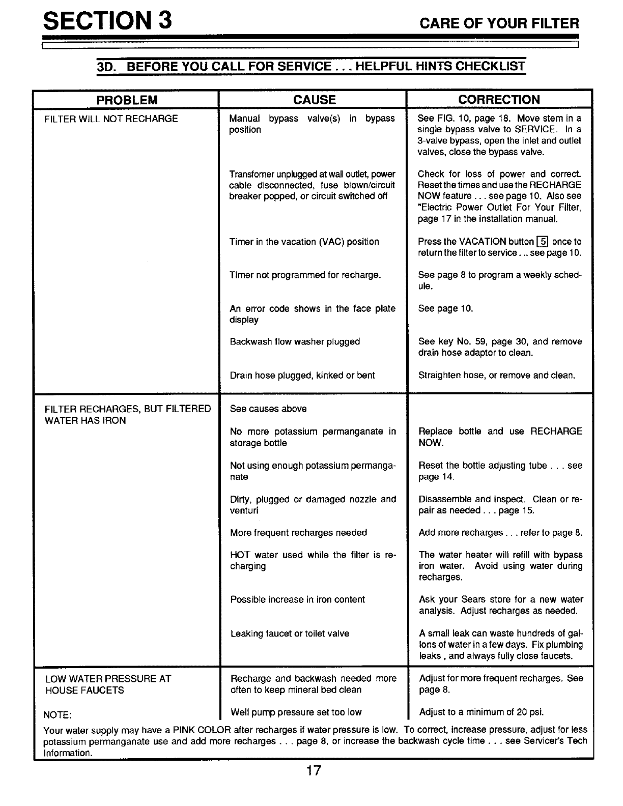
3D. BEFORE YOU CALL FOR SERVICE... HELPFUL HINTS CHECKLIST
PROBLEM CAUSE CORRECTION
Manual bypass valve(s) in bypass
position
Transfomer unplugged at wall outlet,power
cable disconnected, fuse blown/circuit
breaker popped, or circuit switched off
Timer in the vacation (VAC) position
Timer not programmed for recharge.
FILTER WILL NOT RECHARGE
FILTER RECHARGES, BUT FILTERED
WATER HAS IRON
LOW WATER PRESSURE AT
HOUSE FAUCETS
An error code shows in the face plate
display
Backwash flow washer plugged
Drain hose plugged, kinked or bent
See causes above
No more potassium permanganate in
storage bottle
Not using enough potassium permanga-
nate
Dirty, plugged or damaged nozzle and
venturi
More frequent recharges needed
HOT water used while the filter is re-
charging
Possible increase in iron content
Leaking faucet or toilet valve
Recharge and backwash needed more
often to keep mineral bed clean
Well pumppressure set too low
NOTE:
See FIG. 10, page 18. Move stem in a
single bypass valve to SERVICE. In a
3-valve bypass, open the inlet and outlet
valves, close the bypass valve.
Check for loss of power and correct.
Reset thetimesandusethe RECHARGE
NOW feature.., see page 10. Also see
"Electric Power Outlet For Your Filter,
page 17 in the installation manual.
Press the VACATION button [] once to
return the filter to service.., see page 10.
See page 8 to program a weekly sched-
ule.
See page 10.
See key No. 59, page 30, and remove
drain hose ada_orto clean.
Straighten hose, or remove and clean.
Replace bottle and use RECHARGE
NOW.
Reset the bottle adjusting tube.., see
page 14.
Disassemble and inspect. Clean or re-
pair as needed.., page 15.
Add more recharges.., refer to page 8.
The water heater will refill with bypass
iron water. Avoid using water during
recharges.
Ask your Sears store for a new water
analysis. Adjust recharges as needed.
A small leak can waste hundreds of gal-
lons of water in a few days. Fix plumbing
leaks, and always fully close faucets.
Adjust for more frequent recharges. See
page 8.
Adjust to a minimum of 20 psi.
Your water supply may have a PINK COLOR after recharges if water pressure is low. To correct, increase pressure, adjust for less
potassium permanganate use and add more recharges.., page 8, or increase the backwash cycle time.., see Servicer's Tech
Information.
17
SECTION 4 OTHERTHINGSTOKNOW
I
4A.
I
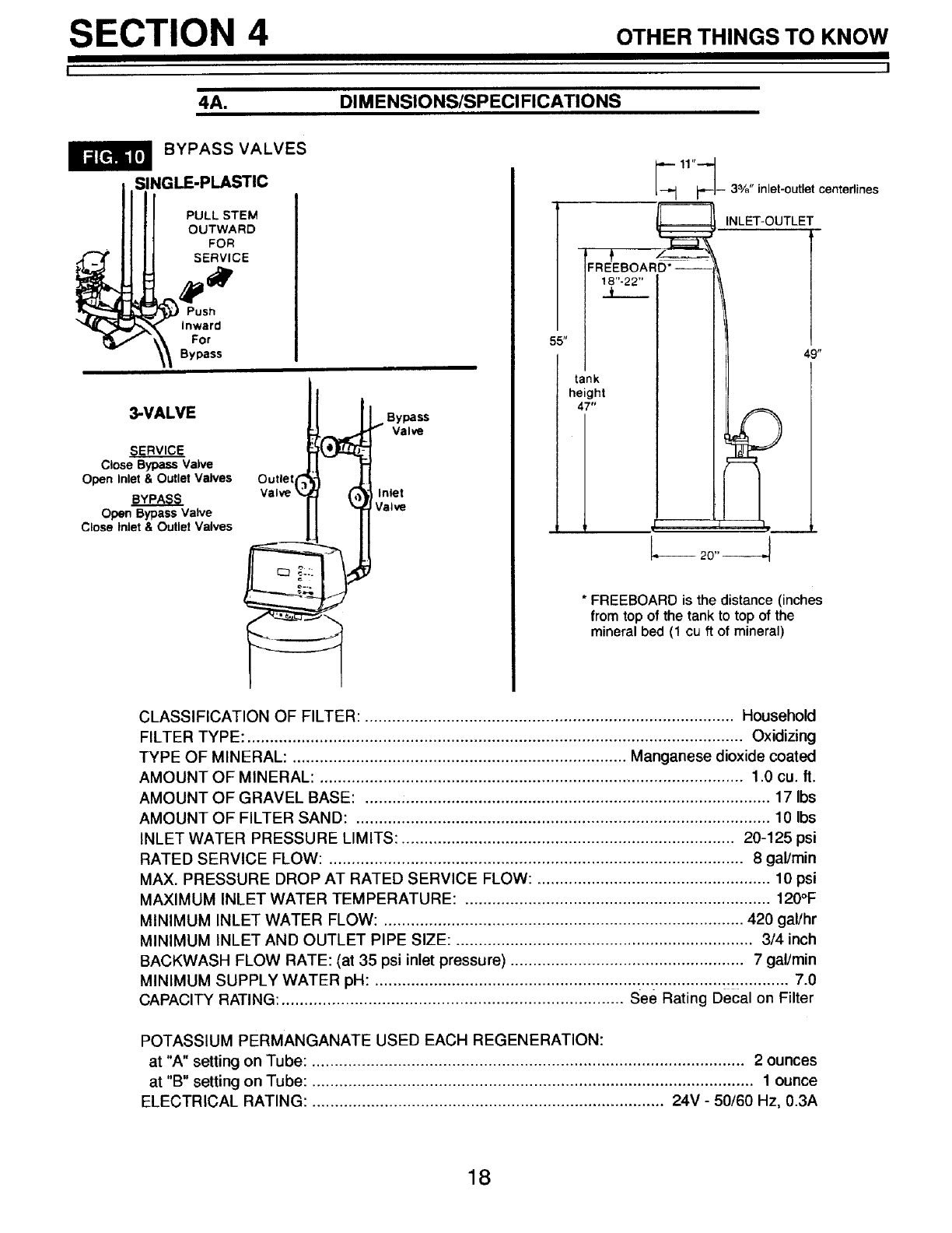
DIMENSIONS/SPECIFICATIONS
BYPASS VALVES
SINGLE-PLASTIC
PULL STEM
OUTWARD
FOR
SERVICE
For
Bypass
_VALVE
SERVICE
Close Bypass Valve
Open Inlet & Outlet Valves
BYPASS
Open Bypass Valve
Close Inlet & Outlet Valves
II II_BYpass
OutletS( _ Valve
Valve_(',_1 Inlet
]1
_ 11"--- 1
_-J-- 3%" inlel-outlet centerlines
-_ INLET-OUTLET
height II I
*FREEBOARD is the distance (inches
from top of the tank to top of the
mineral bed (1 cu ft of mineral)
CLASSIFICATION OF FILTER: .................................................................................. Household
FILTER TYPE: .............................................................................................................. Oxidizing
TYPE OF MINERAL: .......................................................................... Manganese dioxide coated
AMOUNT OF MINERAL: .............................................................................................. 1.0 cu. ft.
AMOUNT OF GRAVEL BASE: .......................................................................................... 17 Ibs
AMOUNT OF FILTER SAND: ............................................................................................ 10 Ibs
INLET WATER PRESSURE LIMITS: .......................................................................... 20-125 psi
RATED SERVICE FLOW: ............................................................................................ 8 gal/min
MAX. PRESSURE DROP AT RATED SERVICE FLOW: .................................................... 10 psi
MAXIMUM INLET WATER TEMPERATURE: .................................................................... 120°F
MINIMUM INLET WATER FLOW: ................................................................................ 420 gal/hr
MINIMUM INLET AND OUTLET PIPE SIZE: .................................................................. 3/4 inch
BACKWASH FLOW RATE: (at 35 psi inlet pressure) .................................................... 7 gal/min
MINIMUM SUPPLY WATER pH: ............................................................................................ 7.0
CAPACITY RATING: ........................................................................... See Rating Decal on Filter
POTASSIUM PERMANGANATE USED EACH REGENERATION:
at "A" setting on Tube: ................................................................................................ 2 ounces
at "B" setting on Tube: .................................................................................................. 1 ounce
ELECTRICAL RATING: .............................................................................. 24V - 50/60 Hz, 0.3A
18
SECTION 5 SERVICER'S TECH. INFORMATION
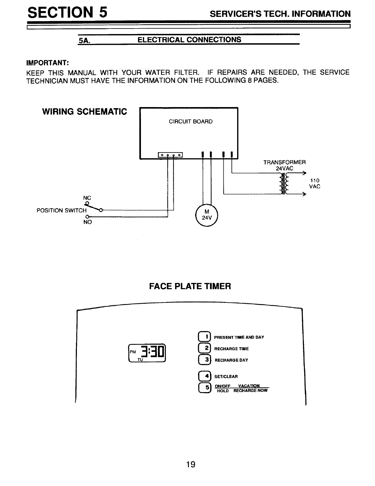
5A. ELECTRICAL CONNECTIONS
IMPORTANT:
KEEP THIS MANUAL WITH YOUR WATER FILTER. IF REPAIRS ARE NEEDED, THE SERVICE
TECHNICIAN MUST HAVE THE INFORMATION ON THE FOLLOWING 8 PAGES.
WIRING SCHEMATIC
NC
POSITION SWITCH'I_
O
NO
CIRCUIT BOARD
._4Y
TRANSFORMER
24VAC
f110
VAC
FACE PLATE TIMER
QRESENT TIME AND DAY
(_ RECHARGE TIME
(_ RECHARGE DAY
SET/CLEAR
_) ONfOFF VACATION
HOLD RECHARGE NOW
19
SECTION 5 SERVlCER'STEC..I.WORMAXIO.
I
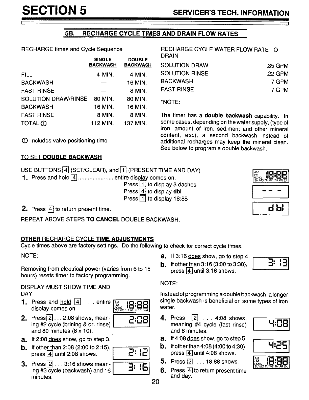
5B. RECHARGE CYCLE TIMES
J
AND DRAIN FLOW RATES
RECHARGE times and Cycle Sequence
SINGLE DOUBLE
BACKWASH BACKWASH
FILL 4 MIN. 4MIN.
BACKWASH -- 16 MIN.
FAST RINSE -- 8 MIN.
SOLUTION DRAW/RINSE 80 MIN. 80 MIN.
BACKWASH 16 MIN. 16 MIN.
FAST RINSE 8 MIN. 8 MIN.
TOTAL Q 112 MIN. 137 MIN.
(_) Includes valve positioning time
TO SET DOUBLE BACKWASH
RECHARGE CYCLE WATER FLOW RATE TO
DRAIN
SOLUTION DRAW
SOLUTION RINSE
BACKWASH
FAST RINSE
*NOTE:
.35 GPM
.22 GPM
7 GPM
7GPM
The timer has a double backwash capability. In
some cases, depending on the water supply, (type of
iron, amount of iron, sediment and other mineral
content, etc.), a second backwash instead of
additional recharges may keep the mineral clean.
See below to program a double backwash.
USE BUTTONS [] (SET/CLEAR), and [] (PRESENT TIME AND DAY)
1. Press and hold [] ...................... entire displ]&y comes on.
Press Ill to display 3 dashes
Press [] to display dbl
Press [] to display 18:88
2, Press [] to return present time.
REPEAT ABOVE STEPS TO CANCEL DOUBLE BACKWASH.
#__,L_il
I_ Ir_q"Qr.Jl
Lsu go TU WE TH FR SA J
Idb=l
OTHER RECHARGE CYCLE TIME ADJUSTMENTS
Cycle times above are factory settings. Do the following to check for correct cycle times.
NOTE:
Removing from electrical power (varies from 6 to 15
hours) resets timer to factory programming.
DISPLAY MUST SHOW TIME AND
DAY
1. Press and _ [] ... entire I,,_,_!L-3:QQI
display comes on. I_isuMOTUlW"'I Ml_'_IWETHFRSAI
2. Pressr2]... 2:08 shows, mean- [2_,01___1
ing #2 cycle (brining & br. rinse) i
and 80 minutes (8 x 10).
a. If 2:08 does show, go to step 3.
b. If otherthan2:08(2:00to 2:15),[ 12]
press [] until 2:08 shows. 2:
3. Press_-]... 3:16 shows mean-
ing #3 cycle (backwash)and 16 [ "7-" I_]
minutes.
b=
5.
6.
20
a. If 3:16 does show, gotostep4.
b. Ifotherthan3:16(3:00to3:30), l
press [] until 3:16 shows.
NOTE:
Instead of programming a double backwash, a longer
single backwash is beneficial on some types of iron
water.
4. Press [] . . . 4:08 shows,
meaning #4 cycle (fast rinse)
and 8 minutes.
a. If 4:08 does show, go to step 5.
If other than 4:08 (4:00 to 4:30),
press [] until 4:08 shows.
Press [] ... 18:88 shows.
Press [] to return present time
and day.
SECTION 5 SERVICER'S TECH. INFORMATION
I
5C. DIAGNOSTICS
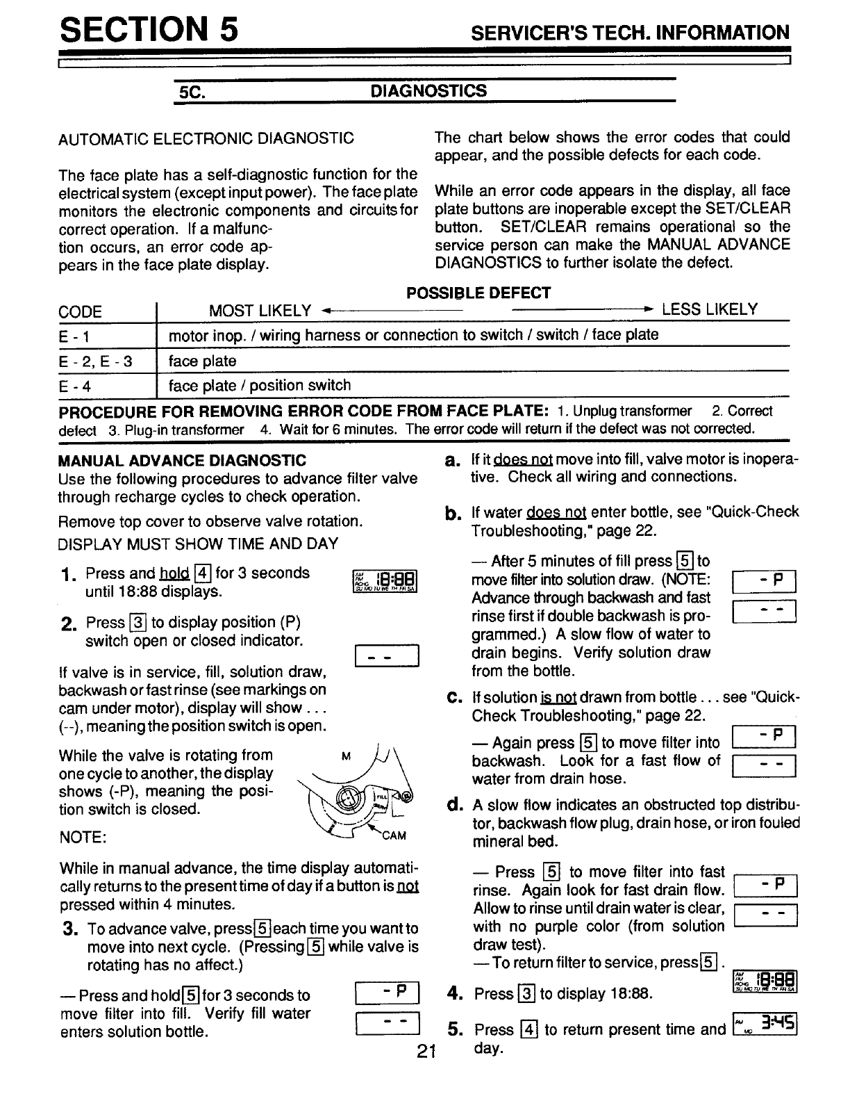
AUTOMATIC ELECTRONIC DIAGNOSTIC
The face plate has a self-diagnostic function for the
electrical system (except input power). The face plate
monitors the electronic components and circuitsfor
correct operation. If a malfunc-
tion occurs, an error code ap-
pears in the face plate display.
CODE
E-1
E-2, E-3
E-4
The chart below shows the error codes that could
appear, and the possible defects for each code.
While an error code appears in the display, all face
plate buttons are inoperable except the SET/CLEAR
button. SET/CLEAR remains operational so the
service person can make the MANUAL ADVANCE
DIAGNOSTICS to further isolate the defect.
POSSIBLE DEFECT
MOST LIKELY -, ,- LESS LIKELY
motor inop. /wiring harness or connection to switch /switch /face plate
face plate
face plate /position switch
PROCEDURE FOR REMOVING ERROR CODE FROM FACE PLATE: 1. Unplug transformer 2. Correct
defect 3. Plug-in transformer 4. Wait for 6 minutes. The error code will return ifthe defect was not corrected.
MANUAL ADVANCE DIAGNOSTIC a.
Use the following procedures to advance filter valve
through recharge cycles to check operation.
Remove top cover to observe valve rotation, b.
DISPLAY MUST SHOW TIME AND DAY
1. Press and hold [] for 3 seconds
until 18:88 displays.
2. Press [] to display position (P)
switch open or closed indicator.
If valve is in service, fill, solution draw,
backwash or fast rinse (see markings on
cam under motor), display will show...
(--), meaning the position switch is open.
While the valve is rotating from
one cycle to another, the display
shows (-P), meaning the posi-
tion switch is closed.
NOTE:
M
If it does not move into fill, valve motor is inopera-
tive. Check all wiring and connections.
Cl
dl
If water does not enter bottle, see "Quick-Check
Troubleshooting," page 22.
-- After 5 minutes of fill press [] to
move filter into solution draw. (NOTE: [ - P1
Advance t_rough backwash and fast
rinse first if double backwash is pro- L - " 1
grammed.) A slow flow of water to
drain begins. Verify solution draw
from the bottle.
If solution isnot drawn from bottle.., see "Quick-
Check Troubleshooting," page 22.
-- Again press [] to move filter into { -p I
backwash. Look for a fast flow of I - - I
water from drain hose. II
A slow flow indicates an obstructed top distribu-
tor, backwash flow plug, drain hose, or iron fouled
mineral bed.
While in manual advance, the time display automati-
cally returns to the present time of day if a button is not
pressed within 4 minutes.
3. To advance valve, press[]each time you wantto
move into next cycle. (Pressing [] while valve is
rotating has no affect.)
-- Press and hold[] for 3 seconds to
move filter into fill. Verify fill water
enters solution bottle.
I -Pl 4.
[ --J s.
21
-- Press [] to move filter into fast
rinse. Again look for fast drain flow. [
Allow to rinse until drain water is clear,
with no purple color (from solution L
draw test).
-- To return filter to service, press[_].
Press [] to display 18:88.
Press [] to return present time and
day.
SECTION 5 SERVICER'S TECH. INFORMATION
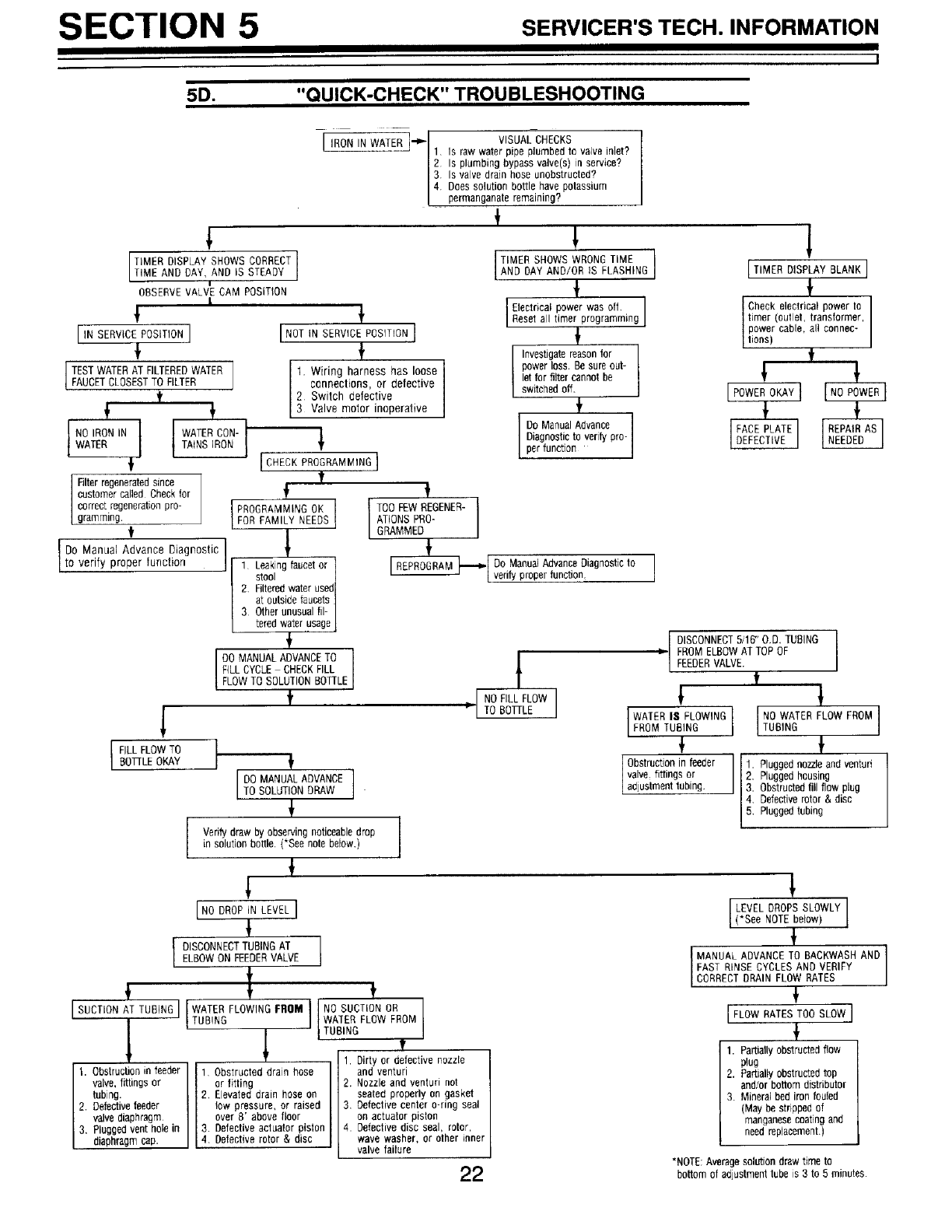
5D. "QUICK-CHECK" TROUBLESHOOTING
[IRONINWATER--_[ VISUALCHECKS
'11. Is raw water pipe plumbed tn valve inlet?
/ 2 Is plumbing bypass valve(s) in service?
13. Is valve drain hose unobstructed?
14. Does solution bottle have potassium
[ = permanganate remaining?
{
1
TIMER DISPLAY SHOWS CORRECTI
TIME AND DAY.,AND IS STEADY
OBSERVEVALVE CAM POSITION
|
!
fIN SERVICE POSITION I
!
TESTWATERAT FILTEREDWATERFAUCETCLOSESTTO FILTER
t
I !
1NO'RON'Nt t WATERCON"1
WATER TAINS IRON
I
Filter regeneratedsince
customer called Check for
correct regenerationpro-
gramming. f
I NOT IN SERVICE POSITION I
t
conneolions, or delective
Switch defective
Valve motor inoperative
1
IO.EOKRROGRAMMINGI
?f
I PROGRAMMING OK TOO FEWREGENER-FOR FAMILY NEEDS ATIONSPRO-
GRAMMED
1
IILeakingfaucet or
stool
2. Filtered water used
at outside faucets
3 Other unusual fil-
tered water usage
I DO MANUAL ADVANCETO ]
FILL CYCLE CHECKFILL
FLOWTO SOLUTIONBOTTLE
t
!
TIMER SHOWS WRONGTIME
AND DAY AND/OR S FLASHING
t
Electrical power was off.
Reset a I timer programming
!
Investigate reasonlor
power loss Be sure out-
let for filter cannot be
switched off.
Do Manual Advance
Diagnostic to verify pro-
per function
I
I Do Manual Advance Diagnostic
to verify proper function
l !
DO MANUAL ADVANCE
TO SOLUTON DRAW
Verify draw by observing noticeabledrop
in solution bottle, (*See note below,)
1
FILL FLOWTO
BOTTLEOKAY
INODROPiNLEVELI
I DISCONNECTTUBING ATELBOWON FEEDERVALVE
÷
I REPROGRAM_-_-i,,[ Do Manual Advance Diagnosticto
--I verify proper function, ]
I
NO FILL FLOW /
/
TO BOTILE ]
I DISCONNECT5/16" O.D. TUBING
B,, FROMELBOW ATTOP OF
FEEDERVALVE.
!
WATER I$ FLOWING
FROM TUBING
{
Obstruction in feeder
valve fittings or
adjustment tubing.
1
[T,MERD,SRLAYBLANK1
Check electrical power to
timer (outlet, transformer,
power cable, all connec-
lions) t
POWEROKAY t
}_
FACE PLATE ]DEFECTIVE
SUeT ON AT TUB NO WATER FLOWING FROM NO SUCTION OR
' I ' I TUBING I ] WATER FLOW FROM I
[ ' 1 ' , TUB,NG , ,
•r 1 Dirty or defective nozzle
t. Obstruction in feede 1 Obstructed drain hose ' and venturi
valve, fittings or or fitting 2. Nozzle and venturi not
tubing. 2. Elevated drain hose on seated properly on gasket
2. Defective feeder tow pressure, or raised 3. Defaclive center o-ring seal
valve diaphragm over 8' above floor on actuator piston
3. Plugged vent hole in 3. Defective actuator piston I I 4. Defective disc seal, rater,
daphragm cap. 4. Defective rotor & disc wave washer, or other inner
'[valve failure
22
!
LEVEL DROPSSLOWLY
(*See NOTE below)
I MANUAL ADVANCE TO BACKWASH AND
FAST RINSE CYCLES AND VERIFY
CORRECTDRAIN FLOW RATES
I
IFLoWRATESTOOSLOWI
Partially obstructed top
and;or bottom distributor
Mineral bed iron fouled
(May be stripped of
manganesecoating and
need replacement.)
*NOTE: Average solution draw time to
bottom of adjustment tube is 3 to 5 minutes.
t
NO WATER FLOW FROM
TUB NG !
1. Plugged nozzleand venturi
2. Plugged huusing
3. Obstructed fill flow plug
4 Defective rotor & disc
5. Plugged tubing
SECTION 5 SERVICER'STECH. INFORMATION
I
5E.
I
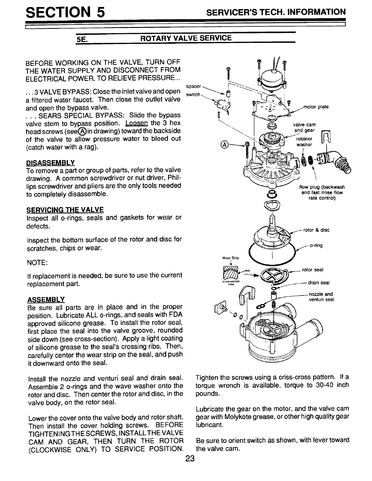
ROTARY VALVE SERVICE
BEFORE WORKING ON THE VALVE, TURN OFF
THE WATER SUPPLY AND DISCONNECT FROM
ELECTRICAL POWER. TO RELIEVE PRESSURE...
.•• 3 VALVE BYPASS: Close the inlet valve and open
a filtered water faucet. Then close the outlet valve
and open the bypass valve.
•.. SEARS SPECIAL BYPASS: Slide the bypass
valve stem to bypass position. Loosen the 3 hex
head screws (see(_)in drawing) toward the backside
of the valve to allow pressure water to bleed out
(catch water with a rag).
DISASSEMBLY
To remove a part or group of parts, refer to the valve
drawing. Acommon screwdriver or nut driver, Phil-
lips screwdriver and pliers are the only tools needed
to completely disassemble.
SERVICING THE VALVE
Inspect all o-rings, seals and gaskets for wear or
defects.
Inspect the bottom surface of the rotor and disc for
scratches, chips or wear.
NOTE:
If replacement is needed, be sure to use the current
replacement part.
ASSEMBLY
Be sure all parts are in place and in the proper
position. Lubricate ALL o-rings, and seals with FDA
approved silicone grease. To install the rotor seal,
first place the seal into the valve groove, rounded
side down (see cross-section). Apply alight coating
of silicone grease to the seal's crossing ribs. Then,
carefully center the wear strip on the seal, and push
it downward onto the seal.
Install the nozzle and venturi seal and drain seal.
Assemble 2 o-rings and the wave washer onto the
rotor and disc. Then center the rotor and disc, in the
valve body, on the rotor seal.
Lower the cover onto the valve body and rotor shaft.
Then install the cover holding screws. BEFORE
TIGHTENING TH E SCREWS, INSTALLTHE VALVE
CAM AND GEAR, THEN TURN THE ROTOR
(CLOCKWISE ONLY) TO SERVICE POSITION•
plate
flow plug (backwash
and fast rinse flow
rate control)
&disc
venturi seal
Tighten the screws using a criss-cross pattern. If a
torque wrench is available, torque to 30-40 inch
pounds.
Lubricate the gear on the motor, and the valve cam
gear with Molykote grease, or other high quality gear
lubricant.
Be sure to orient switch as shown, with lever toward
the valve cam.
23
SECTION 5
5F.
SERVICER'S TECH. INFORMATION
I
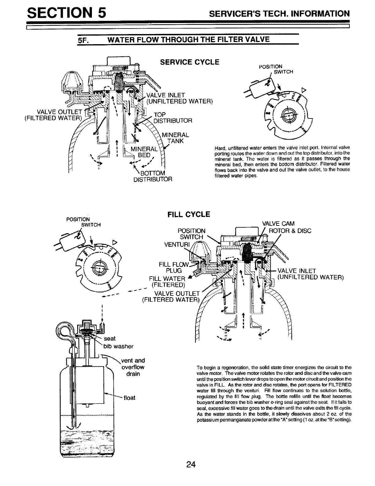
WATER FLOW THROUGH THE FILTER VALVE
VALVE OUTLET
(FILTERED WATER'
SERVICE CYCLE
,VALVE INLET
(UNFILTERED WATER)
TOP
DISTRIBUTOR
MINERAL
TANK
I_--MINERAL
BED •
4,.,t
BOTTOM
DISTRIBUTOR
POSITION
WITCH
Hard, unfiltered water enters the valve inlet port. Internal valve
porting routes the water down and out the top distributor, into the
mineral tank. The water is filtered as it passes through the
mineral bed, then enters the bottom distributor. Filtered water
flows back into the valve and out the valve outlet, to the house
filtered water pipes.
POSITION
SWITCH
I
I
I
seat
washer
vent and
overflow
drain
FILL CYCLE
POSITION
SWITCH
VENTURI
VALVECAM
ROTOR & DISC
FILL
PLUG
FILL WATER =
(FILTERED)
VALVE
(FILTERED WATER
INLET
(UNFILTERED WATER)
To begin a regeneration, the solid state timer energizes the circuit to the
valve motor. The valve motor rotates the rotorand disc and the valve cam
until the position switch lever drops to open the motor cirudt and position the
valve in FILL. As the rotor and disc rotates, the port opens for FILTERED
water fill through the venturi. Fill flow continues to the solution bottle,
regulated by the fill flow plug. The bottle refills until the float becomes
buoyant and forces the bib washer o-ring seal against the seat. Ifit fails to
seal, excassive fill water goes to the drain until the valve exits the fill cycle.
As the water stands in the bottle, it slowly dissolves about 2 oz. of the
potassium permanganate powder at the "A" setting (1 oz. at the "B" setting).
24
SECTION 5 SERVICER'S TECH. INFORMATION
I I
5F. WATER FLOW THROUGH THE FILTER VALVE
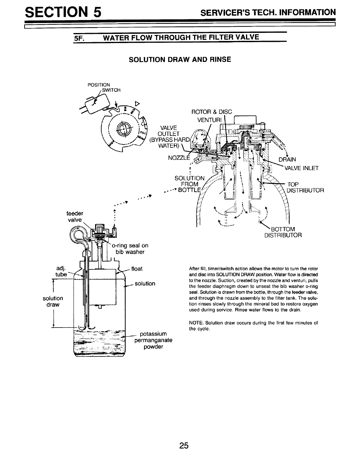
SOLUTION DRAW AND RINSE
POSITION
feeder
valve
=,
°v
seal on
bib washer
ROTOR & DISC
VENTURI
VALVE
OUTLET
(BYPASS
WATER)
NO77LE
SOLUTION
FROM
\
DRAIN
INLET
TOP
DISTRIBUTOR
adj.
solution
draw
After fill, timerlswitch action allows the motor to turn the rotor
and disc into SOLUTION DRAW position. Water flow is directed
to the nozzle. Suction, created by the nozzle and venturi, pulls
the feeder diaphragm down to unseat the bib washer o-ring
seal. Solution is drawn from the bottle, through the feeder valve,
and through the nozzle assembly to the filter tank. The solu-
tion rinses slowly through the mineral bed to restore oxygen
used during service. Rinse water flows to the drain.
potassium
permanganate
powder
NOTE: Solution draw occurs during the first few minutes of
the cycle.
25
SECTION 5 SERVICER'S TECH. INFORMATION
I
5F.
I
WATER FLOW THROUGH THE FILTER VALVE
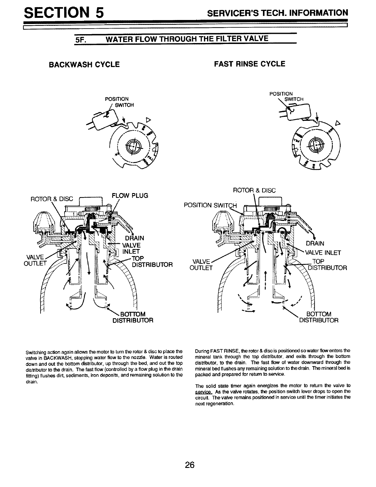
BACKWASH CYCLE FAST RINSE CYCLE
POSITION
,._SWlTCH
POSITION
SWITCH
ROTOR & DISC FLOW PLUG ROTOR & DISC
POSITION SWITCH
DRAIN
VALVE
INLET
OUTLET DISTRIBUTOR VALVE
OUTLET
DRAIN
INLET
TOP
DISTRIBUTOR
%
•/I
-..L.,, BOTTOM
DISTRIBUTOR
Switching action again allows the motor to turn the rotor & disc to place the
valve in BACKWASH, stopping water flow to the nozzle. Water is routed
down and out the bottom distributor, up through the bed, and out the top
distributorto the drain. The fast flow (controlled bya flow plug in the drain
fitting) flushes dirt, sediments, iron deposits, and remaining solution to the
drain.
During FAST RINSE, the rotor & discis positioned so water flow enters the
mineral tank through the top distributor, and exits through the bottom
distributor, to the drain. The fast flow of water downward through the
mineral bed flushes any remaining solutionto the drain. The mineral bed is
packed and prepared for return to service.
The solid state timer again energizes the motor to return the valve to
se_ice. As the valve rotates, the positionswitch lever drops to open the
circuit. The valve remains positioned in service until the timer initiates the
next regeneration.
26

NOTES
I I
27
SECTION 6 REPAIR PARTS
I
11 "_il 12
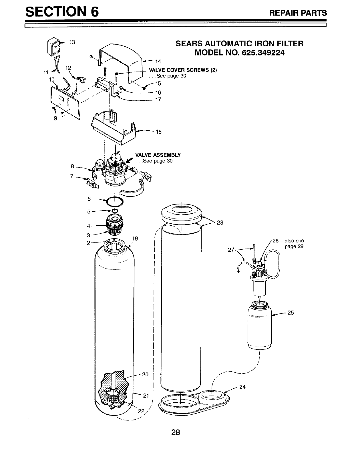
SEARS AUTOMATIC IRON FILTER
MODEL NO. 625.349224
14
VALVE COVER SCREWS (2)
•..See page 30
15
16
17
i
ASSEMBLY
.See page 30
5__..---_
2_ 19
. _ _///
/
26 -also see
27-_ page 29
I
1
/
/
t24
---211
"- /
22./
28
SECTION 6
I
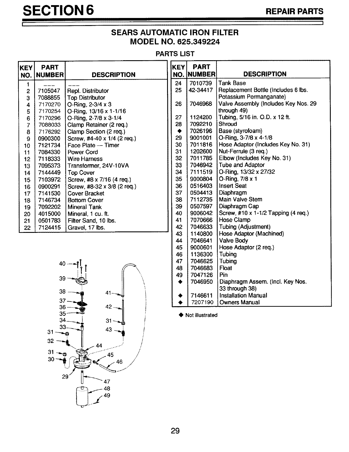
SEARS AUTOMATIC IRON FILTER
MODEL NO. 625.349224
REPAIR PARTS
I
PARTS LIST
KEY I PART
NO. I NUMBER
I
" : 7105047
_ : 7088855
•_ i 7170270
5 ! 7170254
i 7170296
-7088033
8 I 7176292
9 I 0900300
10 I 7121734
4 , 7084330
12 I 7118333
13 I 7095373
14 I7144449
15 I 7103972
16 I 0900291
"'_ '7141530
18 t 7146734
19 I 7092202
20 I 4015000
21 I 0501783
22 I 7124415
i
DESCRIPTION
mD
Repl. Distributor
Top Distributor
O-Ring, 2-3/4 x 3
O-Ring, 13/16 x 1-1/16
O-Ring, 2-7/8 x 3-1/4
Clamp Retainer (2 req,)
Clamp Section (2 req.)
Screw, #4-40 x 1/4 (2 req.)
Face Plate -- Timer
Power Cord
Wire Harness
Transformer, 24V-1 OVA
Top Cover
Screw, #8 x 7/16 (4 req.)
Screw, #8-32 x 3/8 (2 req.)
Cover Bracket
Bottom Cover
Mineral Tank
Mineral, 1 cu. ft.
Filter Sand, 10 Ibs.
Gravel, 17 Ibs.
40---TT•
I 41
34--.._._ 31
32 ---_ ! 44 ........J ;_
31-... O 'i_,, ............ 4"5 /
3°-'!,,,".... 46 /"
49
(EY
NO.
24
25
26
27
28
29
30
31
32
33
34
35
36
37
38
39
40
41
42
43
44
45
46
47
48
49
i
PART
NUMBER
7010739
42-34417
7046968
1124200
7092210
7026196
9001001
7011816
1202600
7011785
7046942
7111519
9000804
0516403
0504413
7112735
0507597
9006042
7070666
7046633
1140800
7046641
9000601
1136300
7046625
7046683
7047126
7046950
7146611
7207190
DESCRIPTION
Tank Base
Replacement Bottle (Includes 6Ibs.
Potassium Permanganate)
Valve Assembly (Includes Key Nos. 29
through 49)
Tubing, 5/16 in. O.D. x 12ft.
Shroud
Base (styrofoam)
O-Ring, 3-7/8 x 4-1/8
Hose Adaptor (Includes Key No. 31)
Nut-Ferrule (3 req.)
Elbow (Includes Key No. 31)
Tube and Adaptor
O-Ring, 13/32 x 27/32
O-Ring, 7/8 x 1
Insert Seat
Diaphragm
Main Valve Stem
Diaphragm Cap
Screw, #10 x1-1/2 Tapping (4 req.)
Hose Clamp
Tubing (Adjustment)
Hose Adaptor (Machined)
Valve Body
Hose Adaptor (2 req.)
Tubing
Tubing
Float
Pin
Diaphragm Assem. (Incl. Key Nos.
33 through 38)
Installation Manual
Owners Manual
Not illustrated
29
SECTION 6 REPAIRPARTS
I I
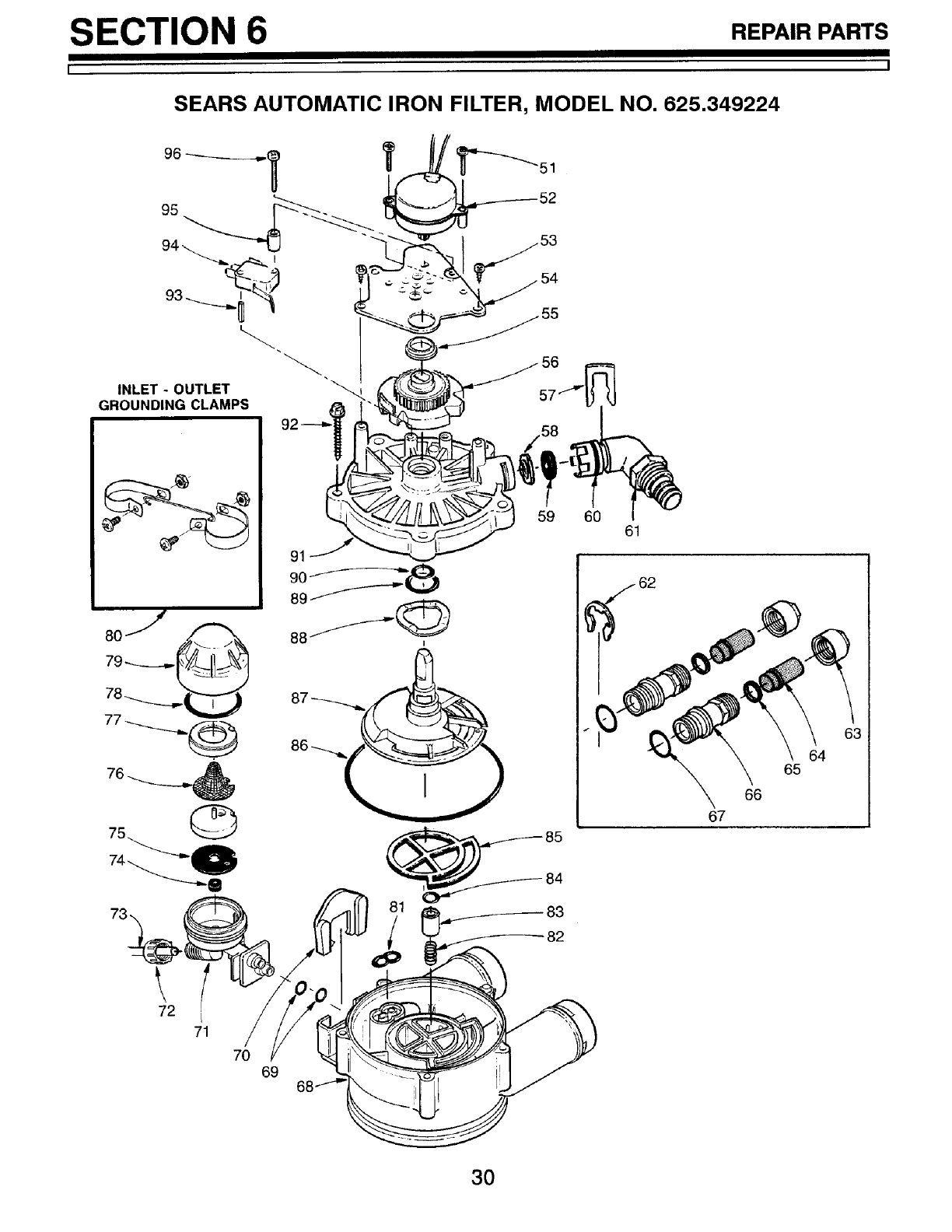
SEARS AUTOMATIC IRON FILTER, MODEL NO. 625.349224
INLET - OUTLET
GROUNDING CLAMPS
59 60
70 69
61
64
65
66
67
3O
SECTION 6 REPAIRPARTS
I I
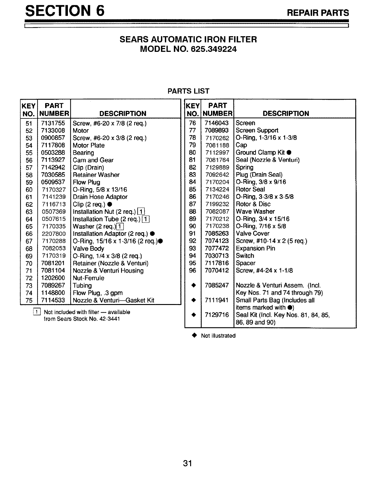
SEARS AUTOMATIC IRON FILTER
MODEL NO. 625.349224
KEY PART
NO. NUMBER
51 7131755
52 7133008
53 0900857
54 7117808
55 0503288
56 7113927
57 7142942
58 7030585
59 0509537
60 7170327
61 7141239
62 7116713
63 0507369
64 0507615
65 7170335
66 2207800
67 7170288
68 7082053
69 7170319
70 7081201
71 7081104
72 1202600
73 7089267
74 1148800
75 7114533
DESCRIPTION
Screw, #6-20 x 7/8 (2 req.)
Motor
Screw, #6-20 x 3/8 (2 req.)
Motor Plate
Bearing
Cam and Gear
!Clip (Drain)
Retainer Washer
Flow Plug
O-Ring, 5/8 x 13/16
Drain Hose Adaptor
Clip (2 req.) •
Installation Nut (2 req.) []
Installation Tube (2 req.) []
Washer (2 req.)[T]
Installation Adaptor (2 req.) •
O-Ring, 15/16 x 1-3/16 (2 req.)•
Valve Body
:O-Ring, 1/4 x 3/8 (2 req.)
Retainer (Nozzle & Venturi)
Nozzle & Venturi Housing
Nut-Ferrule
Tubing
Flow Plug, .3 gpm
Nozzle & Venturi_asket Kit
r_ Not included with filter -- available
from Sears Stock No. 42-3441
PARTS LIST
=KEY
NO.
76
77
78
79
80
81
82
83
84
85
86
87
88
89
90
91
92
93
94
95
96
PART
NUMBER
7146043
7089893
7170262
7081188
7112997
7081764
7129889
7092642
7170204
7134224
7170246
7199232
7082087
7170212
7170238
7085263
7074123
7077472
7030713
7117816
7070412
7085247
7111941
7129716
DESCRIPTION
Screen
Screen Support
O-Ring, 1-3/16 x 1-3/8
Cap
Ground Clamp Kit •
Seal (Nozzle & Venturi)
Spring
Plug (Drain Seal)
O-Ring, 3/8 x 9/16
Rotor Seal
O-Ring, 3-3/8 x 3-5/8
Rotor & Disc
Wave Washer
O-Ring, 3/4 x 15/16
O-Ring, 7/16x 5/8
Valve Cover
Screw, #10-14 x 2 (5 req)
Expansion Pin
Switch
Spacer
Screw, #4-24 x 1-1/8
Nozzle & Venturi Assem. (Incl.
Key Nos. 71 and 74 through 79)
Small Parts Bag (Includes all
items marked with •)
Seal Kit (Incl. Key Nos. 81, 84, 85,
86, 89 and 90)
•Not illustrated
31
_ARS
OWNER'S
MANUAL
MODEL NO.
625.349224
The model number of
your water filter is found
on the rating decal. This
decal is on the backside
of the top cover.
When requesting service
or ordering parts, always
provide the following in-
formation:
• Product Type
• Model Number
• Part Number
• Part Description
Kenmore
Automatic Iron Filter
For the repair or replacement parts you need
delivered directly to your home
Call 7am - 7 pm, 7 days a week
1 - 800 - 366 - PART
(1 - 800 - 366 - 7278)
For in-home major brand repair service
Call 24 hours a day, 7 days a week
1 - 800 - 4 - REPAIR
(1 - 800 - 473 - 7247)
For the location of a
Sears Parts and Repair Center in your area
Call 24 hours a day, 7 days a week
1 - 800 - 488 - 1222
For information on purchasing a Sears
Maintenance Agreement, or to inquire
about an existing Agreement
Call 9 am - 5 pm, Monday - Saturday
1 - 800 - 827 - 6655
Sears, Roebuck and Co., Hoffman Estates, IL 60179 U.S.A.
7207190 (2/99)
