Kenmore Clothes Dryer 796 8127 Users Manual
Kenmore-Kenmore-Elite-7-3-Cu-Ft-Electric-Steam-Dryer-White-Owners-Manual-671148 kenmore-kenmore-elite-7-3-cu-ft-electric-steam-dryer-white-owners-manual-671148
ELITE 796.8051 spin_prod_736394412
7968127 ce380d35-89db-45b4-ba63-23d1916a3beb Kenmore Clothes Dryer 796.8127# User Guide |
2015-01-24
: Kenmore Kenmore-Clothes-Dryer-796-8127-Users-Manual-326692 kenmore-clothes-dryer-796-8127-users-manual-326692 kenmore pdf
Open the PDF directly: View PDF ![]() .
.
Page Count: 32

Model/Modelo: 796.8127#, 796.9127#
Kenmore®
Dryer
P/N MFL62512877
Sears Brand Management Corporation
Use & Care Guide
Manual de Uso y Cuidado
English / Español
# = color number, numero de color
®

2
TABLE OF CONTENTS
PRODUCT RECORD
Master Protection Agreements
Kenmore®
•Parts and labor
operating properly under normal use,
well beyond the product warranty.
real protection.
•Expert service
Sears service technicians,
•Unlimited service calls and nationwide service,
•“No-lemon”guarantee
•Productreplacement
•Annual Preventive Maintenance Check at your request
•Fast help by phone – Rapid Resolution.
•
Power surge protection
to
•$250 food loss protection annually
•Rental reimbursement
•10% discount
Some limitations and exclusions apply.
For prices and additional information in the U.S.A.
call 1-800-827-6655.
*Coverage in Canada varies on some items.
For full details call Sears Canada at 1-800-361-6665.
Sears Installation Service
®
Model No
PROTECTION AGREEMENTS
IMPORTANT SAFETY INSTRUCTIONS
GROUNDING REQUIREMENTS
FEATURES AND BENEFITS
Key Parts and Components 7
INSTALLATION INSTRUCTIONS
8
8
8
8
16
16
17
HOW TO USE
Control Panel Features 18
Sorting Loads 22
22
23
25
25
25
25
Damp Dry Signal25
USER MAINTENANCE INSTRUCTIONS
26
26
26
26
26
27
28
TROUBLESHOOTING GUIDE
WARRANTY 32
SERVICE
3
IMPORTANT SAFETY INSTRUCTIONS
READ ALL INSTRUCTIONS BEFORE USE
WARNING:
DANGER:
WARNING:
For your safety, the information in this manual must be followed to
minimizetheriskofreorexplosion,electricshock,ortopreventpropertydamage,personalinjury,
or loss of life.
Donotinstallaclothesdryerwithexibleplasticventingmaterials.Ifaexiblemetal(foiltype)ductisinstalled,
itmustbeofaspecictypeidentiedbytheappliancemanufacturerassuitableforusewithclothesdryers.
Flexible venting materials are known to collapse, be easily crushed, and trap lint. These conditions will obstruct
clothesdryerairowandincreasetheriskofre.
Donotstoreorusegasolineorotherammablevaporsandliquidsinthevicinityofthisapplianceorany
other appliances.
Installationandservicemustbeperformedbyaqualiedinstaller,serviceagency,orthegassupplier.
Install the clothes dryer according to the manufacturer’s instructions and local codes.
Save these instructions.
WHAT TO DO IF YOU SMELL GAS:
1. Do not try to light a match or cigarette, or turn on any gas or electrical appliance.
2. Do not touch any electrical switches. Do not use any phones in your building.
3. Clear the room, building, or area of all occupants.
4. Immediately call your gas supplier from a neighbor’s phone. Carefully follow the gas supplier’s instructions.
5.Ifyoucannotreachyourgassupplier,calltheredepartment.
Your safety and the safety of others is very important.
CAUTION:
SAVE THESE INSTRUCTIONS

IMPORTANT SAFETY INSTRUCTIONS
CALIFORNIA SAFE DRINKING WATER AND
TOXIC ENFORCEMENT ACT
GROUNDING REQUIREMENTS
BASIC SAFETY PRECAUTIONS
WARNING:
WARNING:
Toreducetheriskofre,electricshock,orinjurytopersonswhenusingthisappliance,
follow basic precautions, including the following:
Improper connection of the
equipment-grounding
conductor can result in a
risk of electric shock.
permanent wiring system or an equipment grounding

5
•Properly ground dryer to conform with all governing
codes and ordinances.
•Before use, the dryer must be properly installed as
described in this manual.
•Install and store the dryer where it will not be exposed
to temperatures below freezing or exposed to
the weather.
•All repairs and servicing must be performed by an
authorizedservicetechnicianunlessspecically
recommended in this Use & Care Guide. Use only
authorized factory parts.
•To reduce the risk of electrical shock, do not install the
dryer in humid spaces.
•Connect to a properly rated, protected, and sized
power circuit to avoid electrical overload.
•Gas dryers MUST be exhausted to the outside. Failure
•The dryer exhaust system must be exhausted to the
outside of the dwelling. If the dryer is not exhausted
outdoors,somenelintandlargeamountsof
moisture will be expelled into the laundry area.
•Useonlyrigidmetalorexiblemetal4inchdiameter
duct inside the dryer cabinet or for exhausting to the
outside. Use of plastic or other combustible ductwork
cancauseare.Puncturedductworkcancauseare
•Ductwork is not provided with the dryer, and you
should obtain the necessary ductwork locally. The end
cap should have hinged dampers to prevent backdraft
when the dryer is not in use
•Remove all packing items and dispose of all shipping
materials properly.
•Placedryeratleast18inchesabovetheoorfora
garage installation.
•Keep all packaging from children.
•Do not install near items that produce heat or open
ame
•Do not place candles or cigarettes on top of the
product.
•Removeallprotectivevinyllmfromtheproduct.
•Theexhaustductmustbe4inches(10.2cm)in
diameter with no obstructions. The exhaust duct
should be kept as short as possible. Make sure to
clean any old ducts before installing your new dryer.
•Rigid or semi rigid metal ducting is recommended
for use between the dryer and the wall. In special
installations when it is impossible to make a
connection with the above recommendations, a UL
listedexiblemetaltransitionductmaybeused
between the dryer and wall connection only. The
useofthisductingwillaectdryingtime. Failure to
•DO NOT use sheet metal screws or other fasteners
which extend into the duct that could catch lint and
reducetheeciencyoftheexhaustsystem.
IMPORTANT SAFETY INSTRUCTIONS
SAFETY INSTRUCTIONS FOR INSTALLATION
Exhaust/Ducting:
WARNING:
Toreducetheriskofre,electricshock,orinjurytopersonswhenusingthisappliance,
follow basic precautions, including the following:

6
SAFETY INSTRUCTIONS FOR CONNECTING ELECTRICITY
SAVE THESE INSTRUCTIONS
WARNING:
WARNING:
Toreducetheriskofre,electricshock,orinjurytopersonswhenusingthisappliance,
follow basic precautions, including the following:
Toreducetheriskofre,electricshock,orinjurytopersonswhenusingthisappliance,
follow basic precautions, including the following:
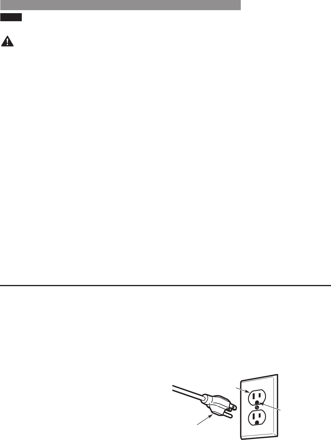
•Do not, under any circumstances, cut or remove
the ground prong from the power cord.
•For personal safety, this dryer must be properly
grounded.
•Refer to the installation instructions in this manual
forspecicelectricalrequirementsforyourmodel.
•This dryer must be plugged into a properly grounded
outlet. Electrical shock can result if the dryer is not
properly grounded. Have the wall outlet and circuit
checkedbyaqualiedelectriciantomakesurethe
outlet is properly grounded.
•The dryer should always be plugged into its own
individual electrical outlet which has a voltage rating
that matches the rating plate.
•Never unplug your dryer by pulling on the power
cord.Alwaysgriptheplugrmlyandpullstraight
out from the outlet.
•Repair or replace immediately all power cords that
have become frayed or otherwise damaged. Do not
use a cord that shows cracks or abrasion damage
along its length or at either end.
•When installing or moving the dryer, be careful not
to pinch, crush, or damage the power cord.
IMPORTANT SAFETY INSTRUCTIONS
7
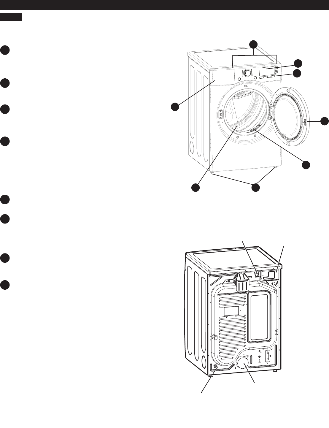
FEATURES AND BENEFITS
KEY PARTS AND COMPONENTS
EASY-TO-USE CONTROL PANEL
TIME AND STATUS DISPLAY
CYCLE MODIFIERS
NOTE:
CHECK VENT
ULTRA-CAPACITY DRUM
EASY-ACCESS REVERSIBLE DOOR
FRONT-MOUNT LINT FILTER
LEVELING FEET
A
B
C
D
E
F
G
H
Power Cord
Outlet
HE
F
G
A
D
C
B
8
INSTALLATION INSTRUCTIONS
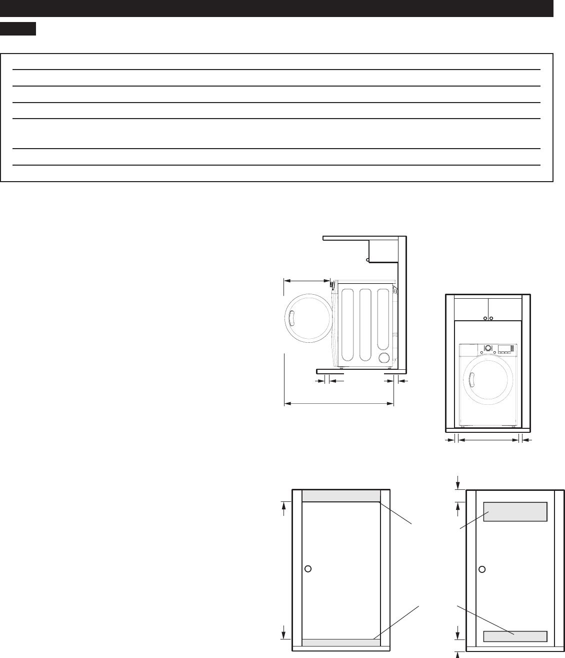
KEY DIMENSIONS AND SPECIFICATIONS
LOCATION REQUIREMENTS
IMPORTANT:
CHOOSE THE PROPER LOCATION
IMPORTANT:
Special Electrical Requirements for Mobile or
Manufactured Homes
CLEARANCES
Additional instructions for closet installations:
/
¼
48 sq. in.
(310 sq. cm. )
24 sq. in.
(155 sq. cm. )
3"
(7.6 cm)
3"
(7.6 cm)
Closet Door Vent Requirements
Vent
Vent
Standard Installation – Side View
/
/
Standard Installation – Front View
INSTALLATION INSTRUCTIONS
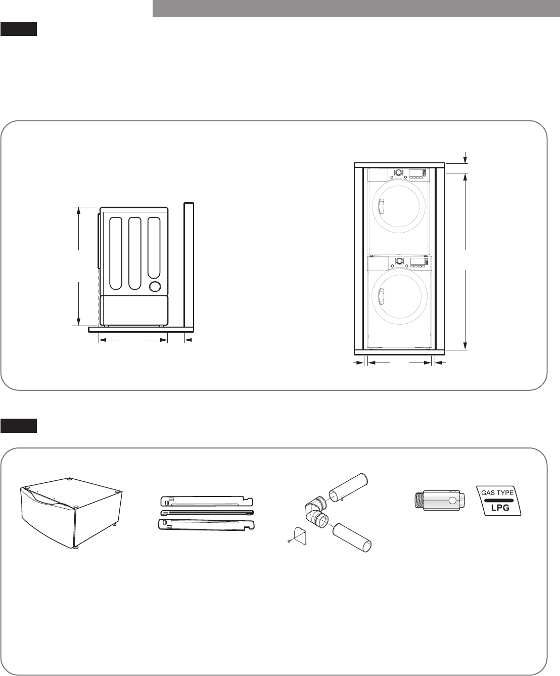
INSTALLATION WITH OPTIONAL PEDESTAL BASE OR STACKING KIT
OPTIONAL ACCESSORIES
IMPORTANT:
/
NOTE:
Standard Installation – Front View
INSTALLATION INSTRUCTIONS
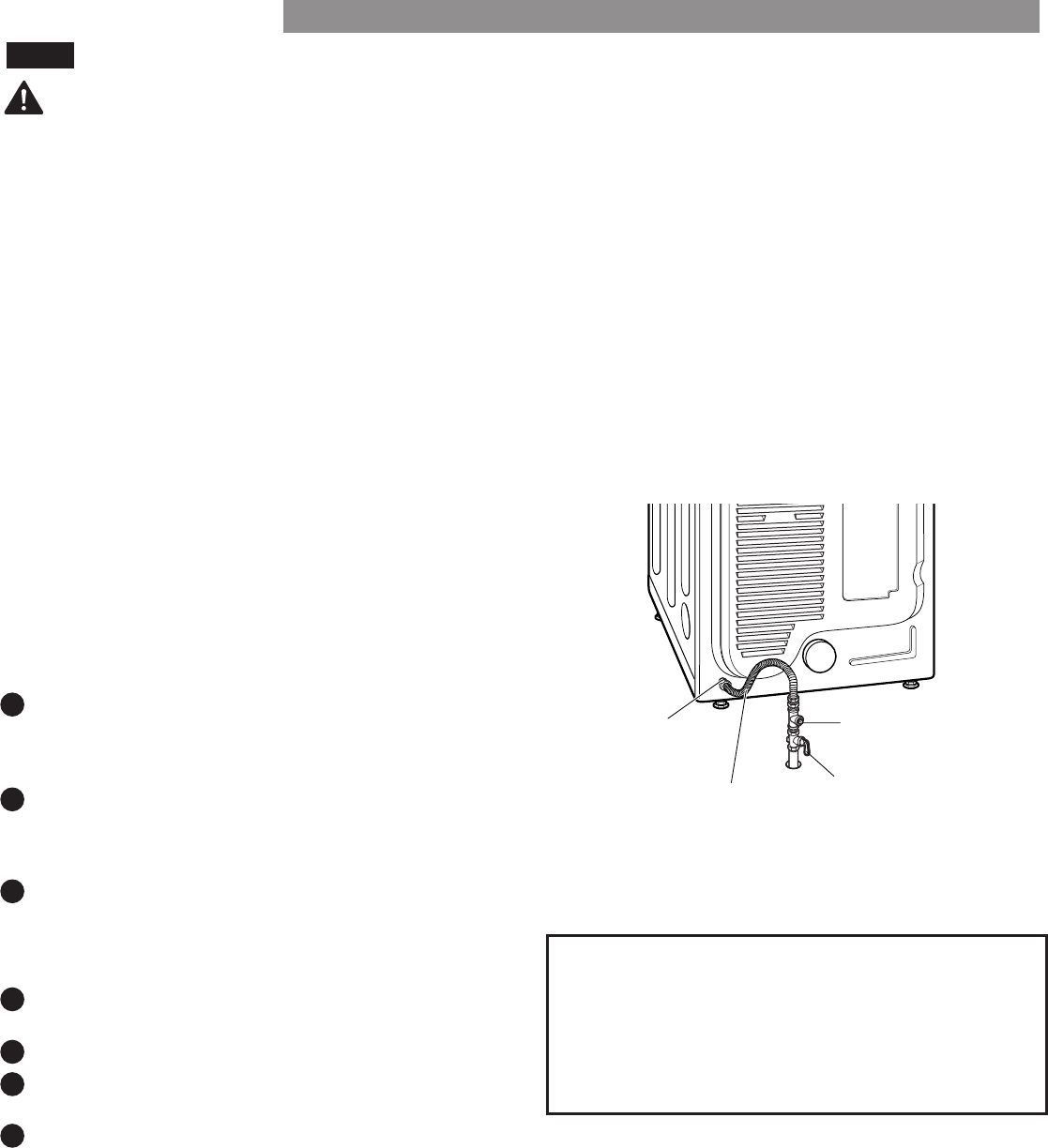
CONNECTING GAS DRYERS
GASREQUIREMENTS(GASMODELSONLY)
WARNING:
•Gassupplyrequirements:Asshippedfromthe
factory,thisdryerisconguredforusewithnatural
gas(NG).Itcanbeconvertedforusewithpropane
(LP)gas.Gaspressuremustnotexceed8inches
watercolumnfor(NG),or13incheswatercolumnfor
(LP).
•Aqualiedserviceorgascompanytechnicianmust
connect the dryer to the gas service.
•Isolate the dryer from the gas supply system by
closingitsindividualmanualshutovalveduringany
pressure testing of the gas supply.
•Supplylinerequirements:Yourlaundryroommust
have a rigid gas supply line to your dryer. In the
UnitedStates,anindividualmanualshutovalve
MUSTbeinstalledwithinatleast6ft.(1.8m)ofthe
dryer, in accordance with the National Fuel Gas Code
ANSI Z223.1 or Canadian gas installation code CSA
B149.1.A⅛inchNPTpipeplugmustbeinstalled.
•If using a rigid pipe, the rigid pipe should be ½ inch
IPS. If acceptable under local codes and ordinances
andwhenacceptabletoyourgassupplier,⅜inch
approved tubing may be used where lengths are less
than20ft.(6.1m).Largertubingshouldbeusedfor
lengthsinexcessof20ft.(6.1m).
ELECTRICAL REQUIREMENTS FOR
GAS MODELS ONLY
•Do not, under any circumstances, cut or remove the
third(ground)prongfromthepowercord. Failure
•For personal safety, this dryer must be properly
grounded.
•Thepowercordofthisdryerisequippedwith
a3-prong(grounding)plugwhichmateswitha
standard3-prong(grounding)walloutlettominimize
the possibility of electric shock hazard from this
appliance.
•This dryer must be plugged into a 120-VAC, 60-Hz.
grounded outlet protected by a 15-ampere fuse or
circuit breaker.
•Where a standard 2-prong wall outlet is encountered,
it is your personal responsibility and obligation to
have it replaced with a properly grounded 3-prong
wall outlet.
•Connect the dryer to the type of gas shown on
the nameplate.
•To prevent contamination of the gas valve, purge the
gas supply of air and sediment before connecting
the gas supply to the dryer. Before tightening the
connection between the gas supply and the dryer,
purge remaining air until the odor of gas is detected.
•DONOTuseanopenametoinspectforgasleaks.
Useanoncorrosiveleakdetectionuid.Failure to do
•UseonlyanewAGA-orCSA-certiedgassupply
linewithexiblestainlesssteelconnectors. Failure to
•Securely tighten all gas connections. Failure to do so
•UseTeontapeorapipe-jointcompoundthatis
insolubleinpropane(LP)gasonallpipethreads.
•DO NOT attempt any disassembly of the dryer;
disassemblyrequirestheattentionandtoolsof
anauthorizedandqualiedservicetechnicianor
company.
grounding
plug
grounding
type wall
11
•Installation and service must be performed by a
qualiedinstaller,serviceagency,orthegassupplier.
•Useonlyanewstainlesssteelexibleconnectorand
anewAGA-certiedconnector.
•Agasshutovalvemustbeinstalledwithin6ft.
(1.8m)ofthedryer.
•Thedryerisconguredfornaturalgaswhen
shipped from the factory. Make sure that the dryer
isequippedwiththecorrectburnernozzleforthe
typeofgasbeingused(naturalgasorpropanegas).
ConnectingtheGasSupply
NOTE:
NOTE:
High-AltitudeInstallations
•Ifnecessary,thecorrectnozzle(fortheLPnozzlekit,
orderpartnumber383EEL3002D)shouldbeinstalled
byaqualiedtechnicianandthechangeshouldbe
noted on the dryer.
•All connections must be in accordance with local
codes and regulations.
•Gas dryers MUST exhaust to the outdoors. Failure to do
WARNING:
1
2
3
4
5
6
7
INSTALLATION INSTRUCTIONS
3/8" NP T Gas
Connection
Gas Supply
Shuto ff Valve
AGA/CSA-Certified
Stainless Steel
Flexible Connector
1/8" NP T Pipe Plug
CONNECTINGGASDRYERS(continued)

12
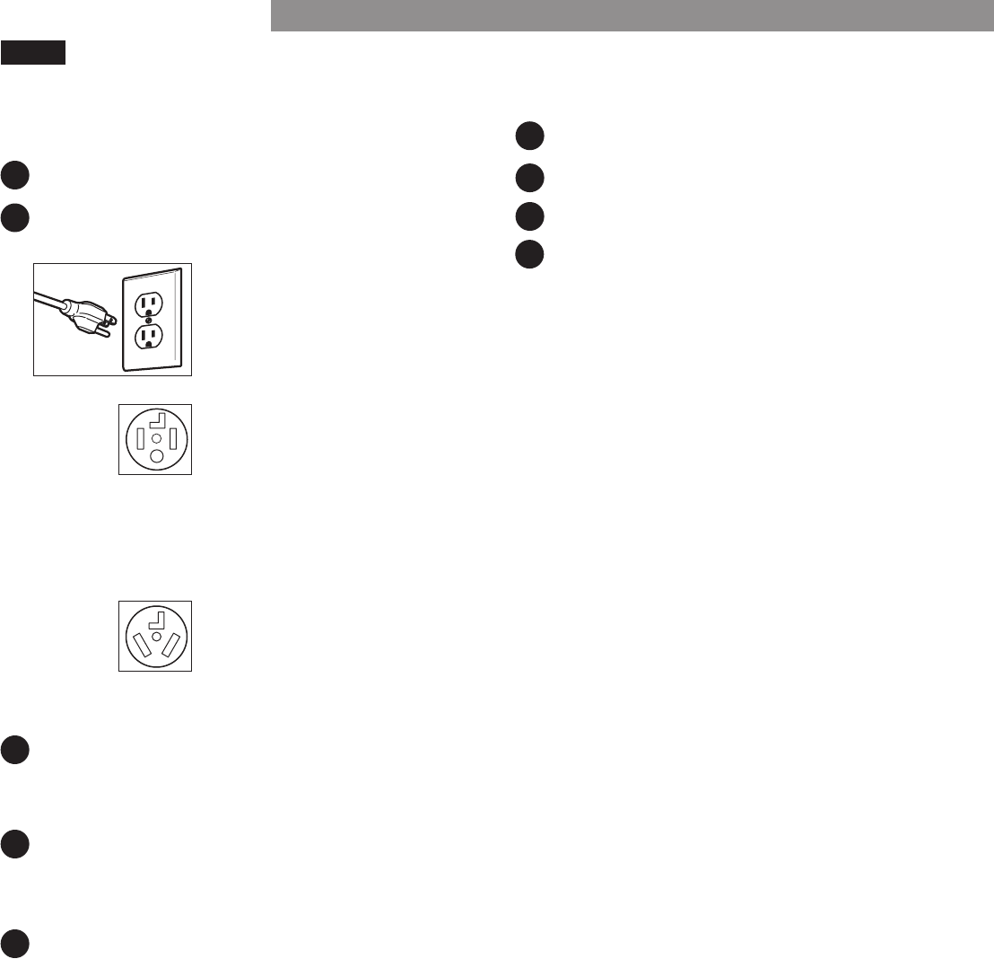
CONNECTING ELECTRIC DRYERS
ELECTRICAL REQUIREMENTS
•Any installation in a manufactured or mobile
home must comply with the Manufactured Home
Construction and Safety Standards Title 24 CFR, Part
3280 or Standard CAN/CSA Z240 MH and local codes
and ordinances.
•A4-wireconnectionisrequiredforallmobileand
manufactured home installations, as well as all new
construction after January 1, 1996. Failure to do so
•This dryer must be connected to a grounded metal,
permanentwiringsystem,oranequipmentgrounding
conductor must be run with the circuit conductors and
connectedtotheequipmentgroundingterminalor
lead on the dryer.
•The dryer has its own terminal block that must be
connected to a separate 240 VAC, 60-Hertz, single
phasecircuit,fusedat30amperes(thecircuitmustbe
fusedonbothsidesoftheline).ELECTRICALSERVICE
FOR THE DRYER SHOULD BE OF THE MAXIMUM
RATE VOLTAGE LISTED ON THE NAMEPLATE. DO
NOT CONNECT DRYER TO 110-, 115-, OR 120-VOLT
CIRCUIT.
•Ifbranchcircuittodryeris15ft.(4.5m)orlessin
length,useUL(UnderwritersLaboratories)listedNo.-
10AWGwire(copperwireonly),orasrequiredby
localcodes.Ifover15ft.(4.50m),useUL-listedNo.-8
AWGwire(copperwireonly),orasrequiredbylocal
codes.Allowsucientslackinwiringsodryercan
be moved from its normal location when necessary.
•Thepowercord(pigtail)connectionbetweenwall
receptacle and dryer terminal block IS NOT supplied
with the dryer. Type of pigtail and gauge of wire
must conform to local codes and with instructions on
the following pages.
•A4-wireconnectionisrequiredforallnew
construction after January 1, 1996. A 4-wire
connection must be used where local codes do not
permit grounding through the neutral wire. Failure to
do so
WARNING:
WARNING:
WARNING:
SpecialElectricalRequirementsforMobile
or Manufactured Homes
ElectricalRequirementsforElectricModelsOnly
INSTALLATION INSTRUCTIONS
13
CONNECTINGELECTRICDRYERS(continued)
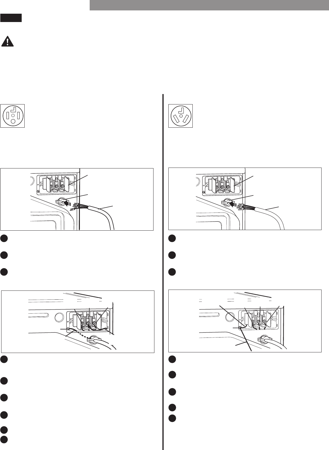
Connect the power cord to the terminal block. Connect
each power cord wire to the terminal block screw that
has the same colored wire. For example, connect the
black power cord wire to the terminal block screw
with the black wire. Failure to follow these instructions
mayresultinashort,overloadreordeath.
Four-WirePowerCord
•A4-wireconnectionisrequiredforall
mobile and manufactured home installations,
as well as all new construction after
January 1, 1996.
30-amp, 240-volt, 4-wire, UL-listed power cord
with #10 AWG-minimum copper conductor
Groundingthroughtheneutralwireisprohibitedfor:(1)
newbranch-circuitinstallations,(2)mobilehomes,(3)
recreationalvehicles,and(4)areaswherelocalcodes
prohibit grounding through the neutral wire.
Three-WirePowerCord
A 3-wire connection is NOT permitted on
new construction after January 1, 1996.
WARNING:
1
4 4
2
5
5
3
6
7
8
9
6
7
8
3
2
1
INSTALLATION INSTRUCTIONS
Power
Cord
3 Wire
Power
Cord
Green Ground Screw
Hot
(Black)
Neutral
Grounding
Wire
Green Wire of
Power Cord
Neutral
(White)
Hot
(Red)
Green Ground Screw
Hot
(Black)
Neutral
Grounding
Wire Neutral
(White)
Hot
(Red)
Ground WireExternal
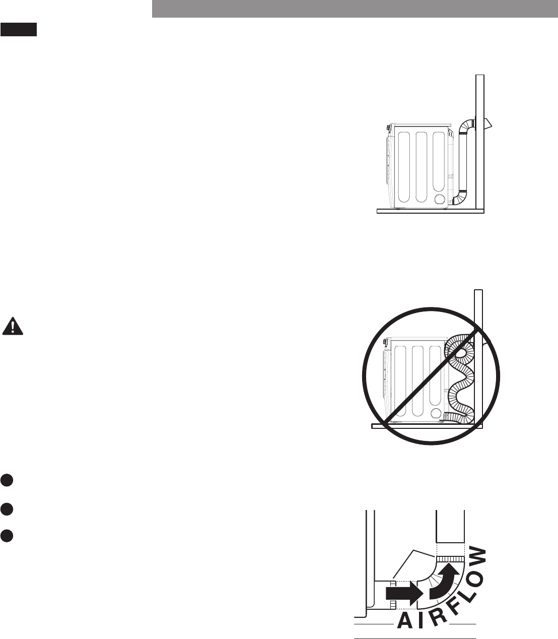
VENTING THE DRYER
CHECK YOUR EXHAUST SYSTEM FOR PROBLEMS
IMPORTANT!
The most common cause of dryer problems is poor
exhaust venting.
•DIRTY OR DAMAGED EXHAUST DUCTS.
•WRONG VENT MATERIAL.
NOTE:
1
2
3
INSTALLATION INSTRUCTIONS
•RESTRICTED OR DAMAGED VENT HOOD.
•EXCESSIVELY LONG VENT.
•DO NOT USE PLASTIC OR FOIL VENTING.
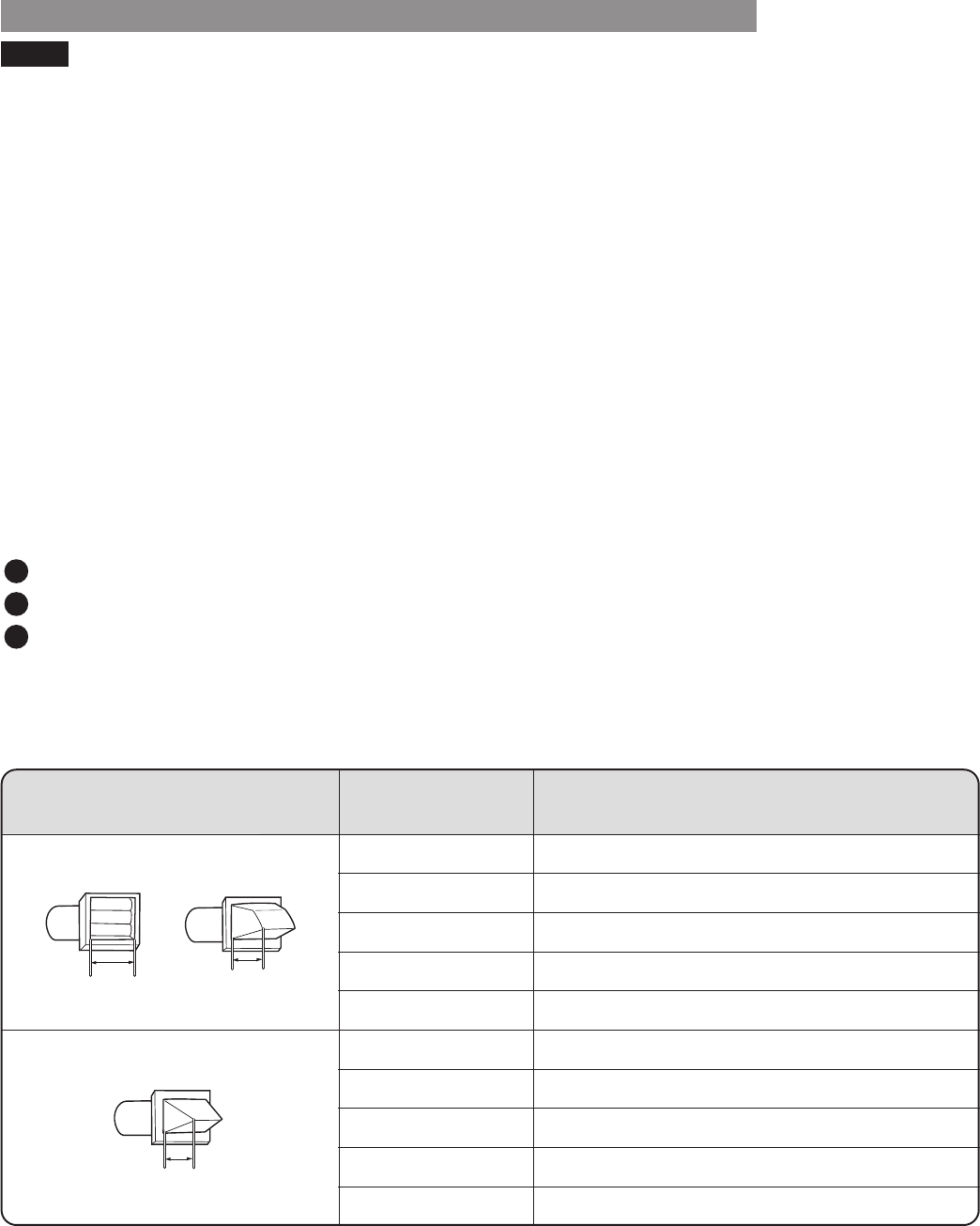
UsingtheDUCTLENGTHCHART(below)
Recommended
Only for Short-Run Installations
4"
(10.2 cm )
4"
(10.2 cm )
21/2"
(6.35 cm )
Number of 90°
Elbows
Vent Hood Type
Maximum length of 4" (10.2 cm )
diameter rigid metal duct
65 feet (19.8 m)
55 feet (16.8 m)
47 feet (13.7 m)
36 feet (11.0 m)
28 feet (8.5 m)
55 feet (16.8 m)
47 feet (13.7 m)
41 feet (12.5 m)
30 feet (9.1 m)
22 feet (6.7 m)
0
1
2
3
4
0
1
2
3
4
15
VENTINGTHEDRYER(continued)
RoutingandConnectingDuctwork
NOTE:
must
must
IMPORTANT:
ConnectingtheDryerVent
WARNING:
1
2
3
INSTALLATION INSTRUCTIONS
Male
16
INSTALLATION INSTRUCTIONS
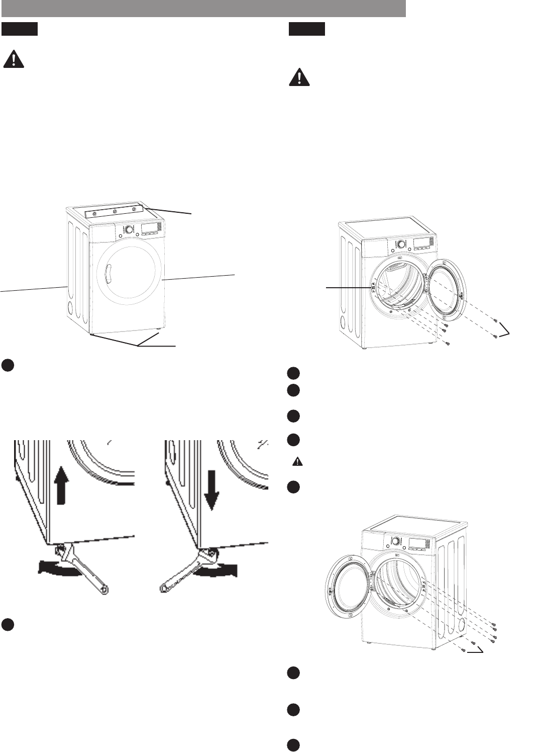
LEVELING THE DRYER REVERSING THE DOOR SWING
NOTE:
NOTE:
CAUTION:
THE DRYER DOOR IS VERY LARGE AND HEAVY.
WARNING: WARNING:
1
2
1
2
3
4
5
6
7
8
INSTALLATION INSTRUCTIONS
Level
Leveling Feet
Leveling Feet
Level
Door
Hinge
17
INSTALLATION INSTRUCTIONS
FINAL INSTALLATION CHECK
NOTE:
TestingDryerHeating
NOTE:
CheckingVenting
1
1
2
3
4
2
3
4
5
INSTALLATION INSTRUCTIONS
18
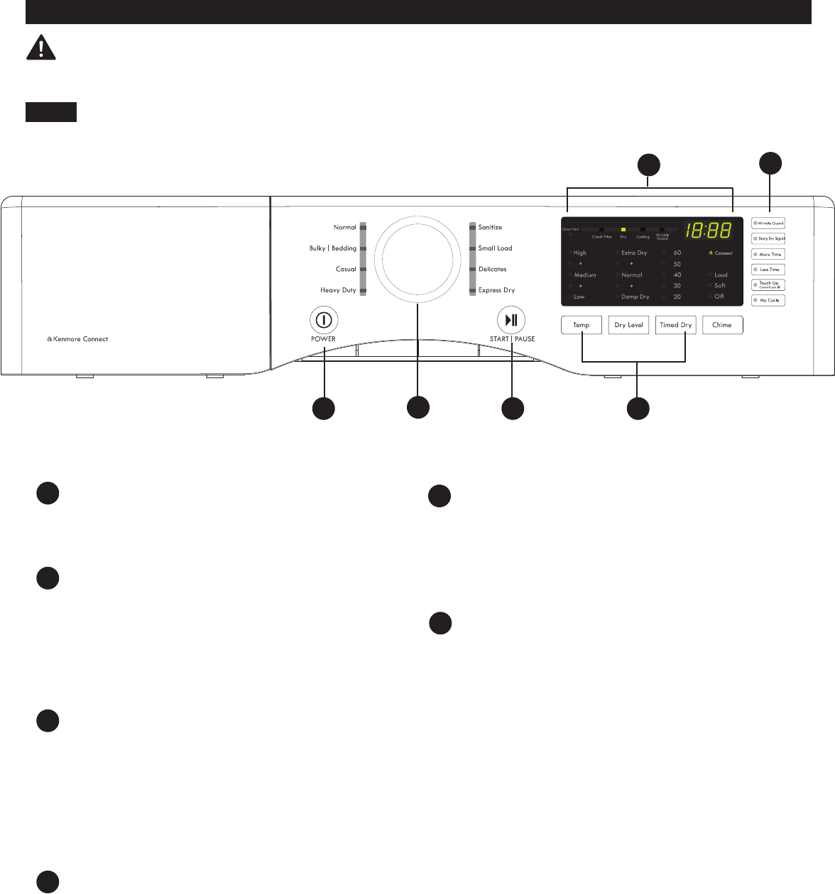
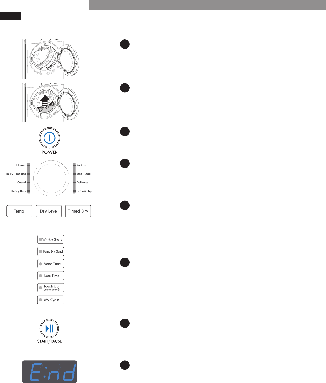
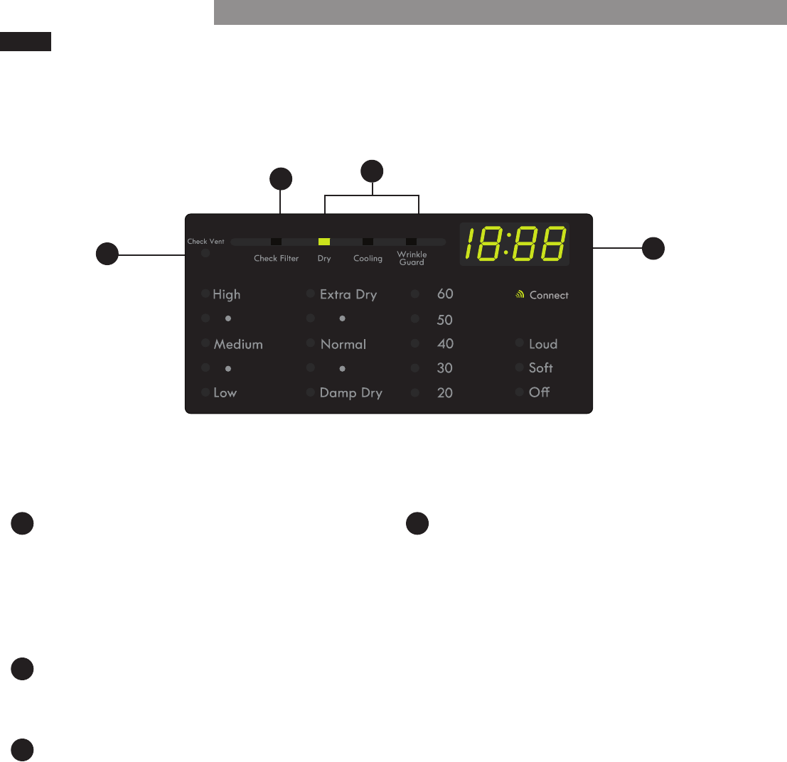
HOW TO USE
CONTROL PANEL FEATURES
POWER(ON/OFF)BUTTON
CYCLE SELECTOR KNOB
START/PAUSE BUTTON
NOTE:
OPTION BUTTONS
CYCLE MODIFIER BUTTONS
TIME AND STATUS DISPLAY
AE
F
B
C
D
WARNING:
Toreducetheriskofre,electricshock,orinjurytopersons,readthisentire
manual, including the Important Safety Instructions, before operating this dryer.
NOTE:
BCA
D
E
F
HOW TO USE
OPERATING THE DRYER
1LOAD THE DRYER
2CLEAN THE LINT FILTER
3TURN ON THE DRYER
ON
4SELECT A CYCLE
5SELECT CYCLE MODIFIERS
NOTE:
6SELECT CYCLE OPTIONS
NOTE:
7BEGIN CYCLE
8END OF CYCLE
*NOTE:
NOTE:
HOW TO USE
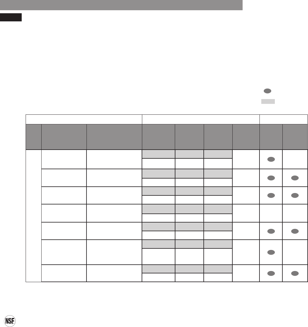
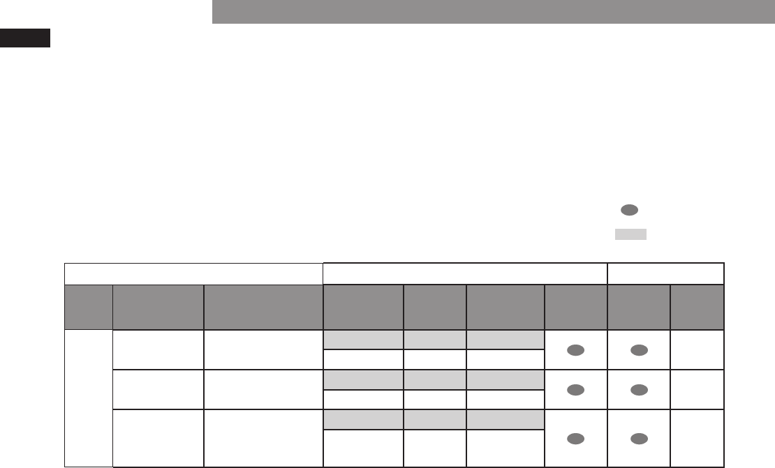
CYCLE GUIDE
Options
Dry Level
More
Damp
Dry
Signal
AUTO DRY
Heavy Duty
items
Normal
Casual
Mid low Normal 32
Medium Normal 55
Normal Medium Normal
Small Load
Normal
Mid low Normal 28
CERTIFIED BY NSF
AutoDryCycles
21
TimedDryCycles
Options
Dry Level
More
Damp
Dry
Signal
TIMED DRY
25
set manually
CYCLE GUIDE
NOTE:
HOW TO USE
22
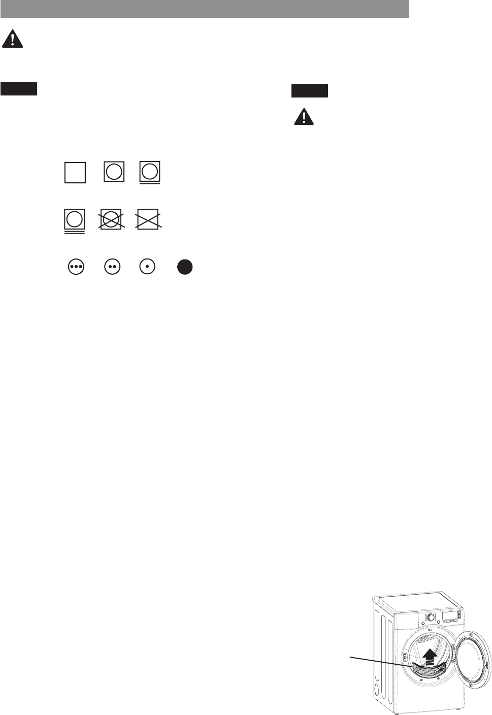
FabricCareLabels
GroupSimilarItems
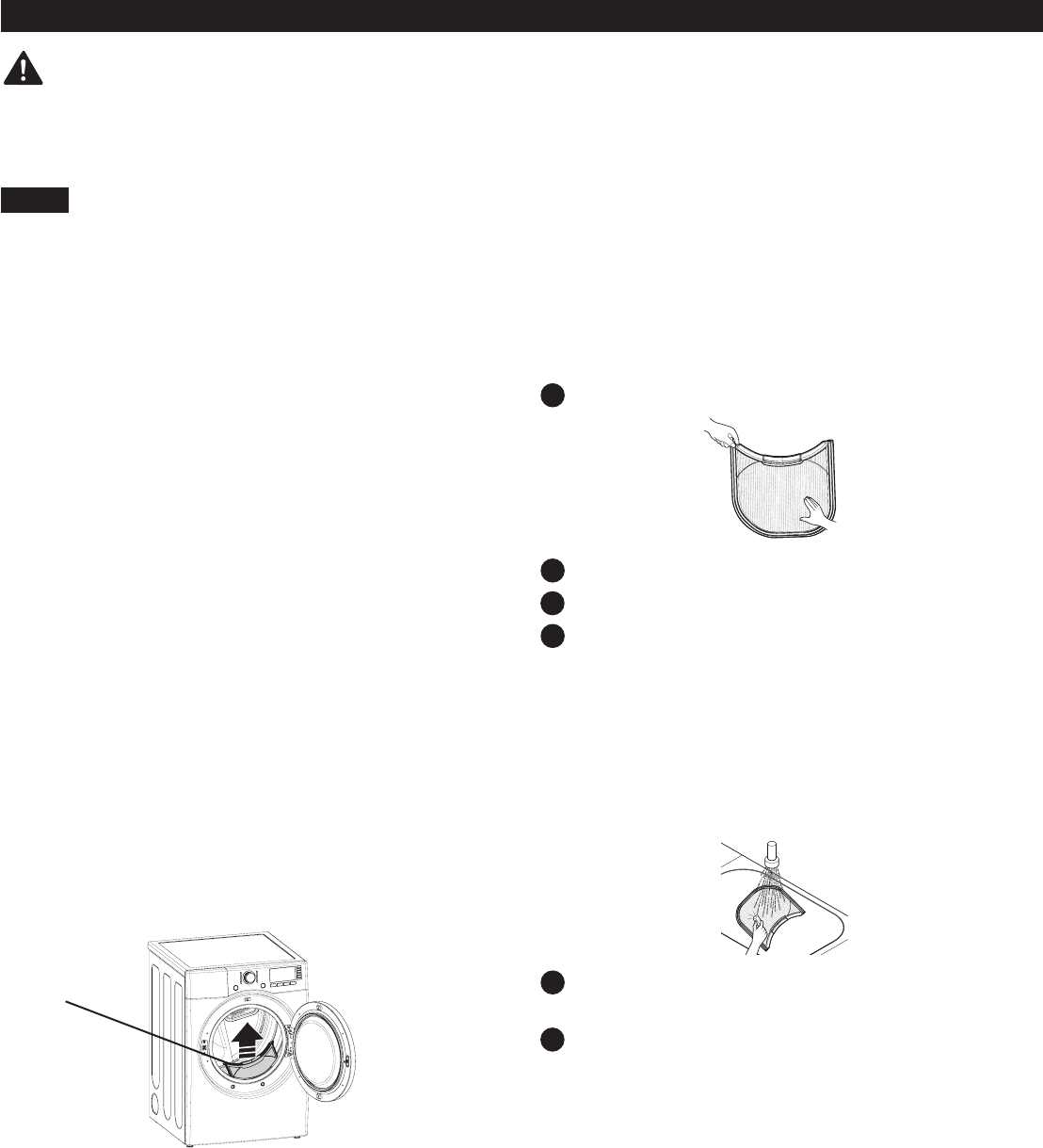
SORTING LOADS LOADING THE DRYER
WARNING:
Toreducetheriskofre,electricshock,orinjurytopersons,readthisentiremanual,
including the Important Safety Instructions, before operating this dryer.
LoadingTips
CHECK THE LINT FILTER BEFORE EVERY LOAD
WARNING:
dry
Heat
setting
Dry Normal Permanent Press/
Do not
Do not dry
Medium Low
HOW TO USE
Lint Filter
23
TIME AND STATUS DISPLAY
TIME DISPLAY
CHECK FILTER LIGHT
CYCLE STATUS INDICATORS
CHECK VENT INDICATOR
(DUCTBLOCKAGESENSINGSYSTEM)
®
A D
B
C
HOW TO USE
BC
A
D
AUTO DRY
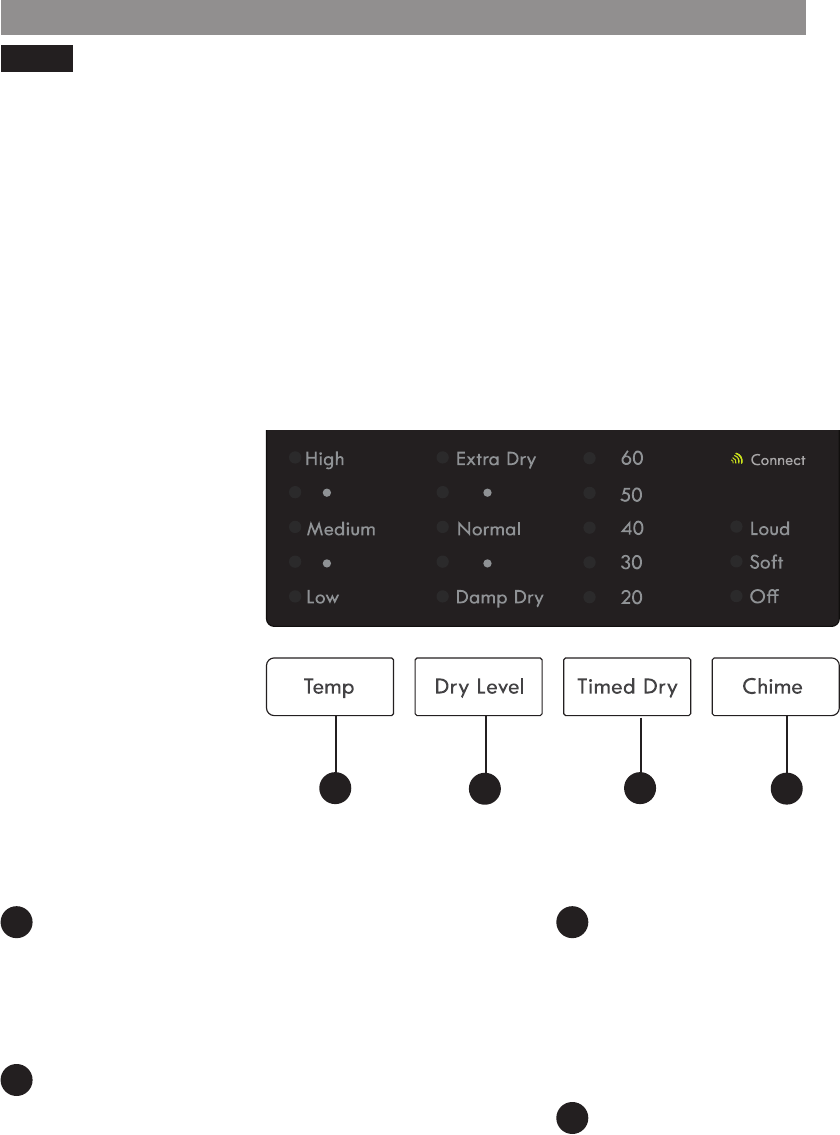
TIMED DRY
NOTE:
CYCLE MODIFIER BUTTONS
TEMP
DRY LEVEL
TIMED DRY
CHIME
A C
B
D
HOW TO USE
ABCD
25
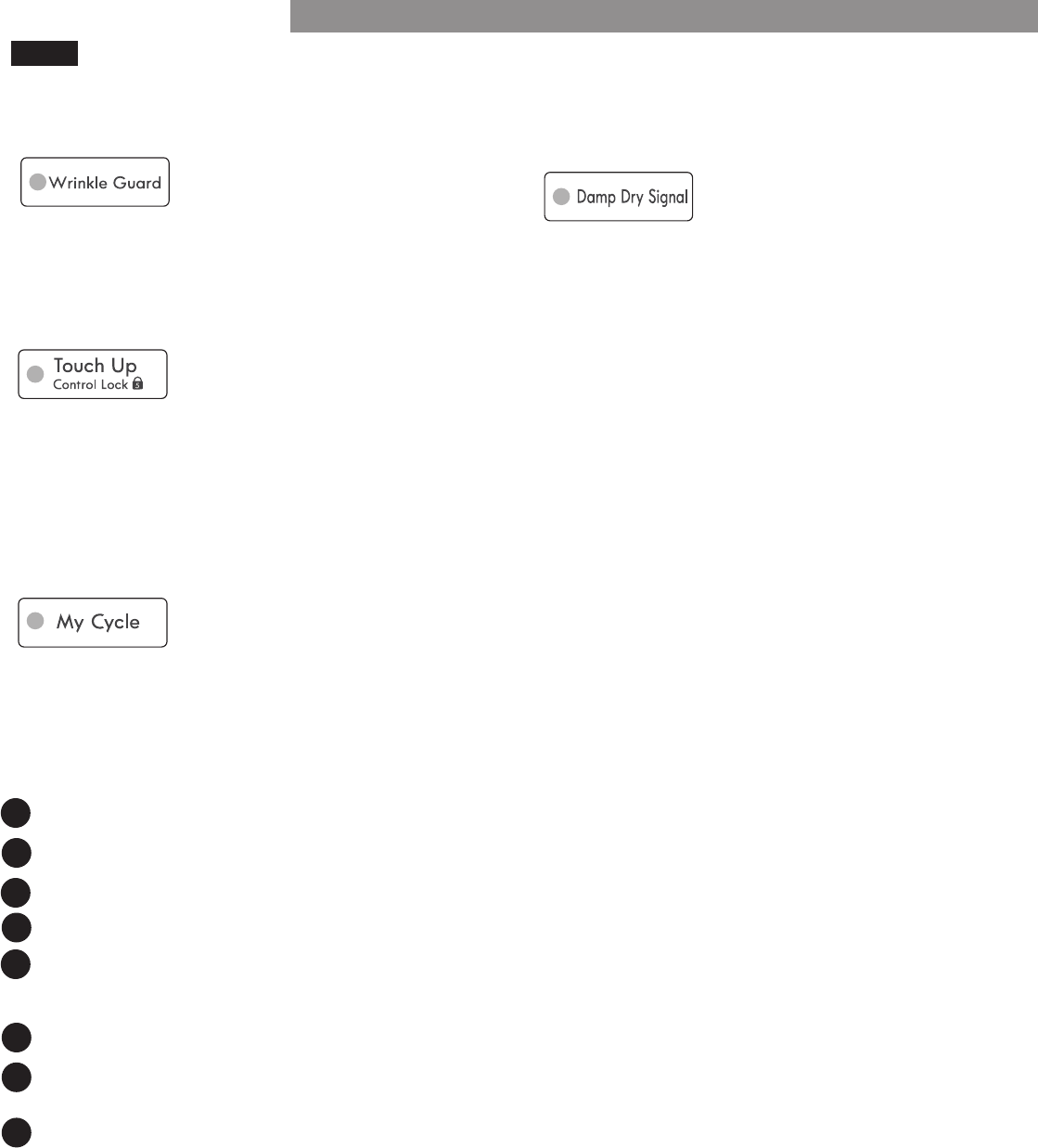
CYCLE OPTIONS AND SPECIAL FEATURES
WRINKLEGUARD
CONTROLLOCK
MYCYCLE
NOTE:
To save a MY CYCLE:
To recall a MY CYCLE:
NOTE:
1
2
3
4
5
1
2
3
HOW TO USE
DAMPDRYSIGNAL
26
USER MAINTENANCE INSTRUCTIONS
REGULAR CLEANING
WARNING:
•Unplugthedryerorturnthepowerobeforecleaningtoavoidtheriskofelectricshock.
•Never use harsh chemicals, abrasive cleaners, or solvents to clean the dryer.
CleaningtheLintFilter
NOTE:
Toremovelintbetweencycles:
Periodicthoroughcleaning:
NOTE:
1
2
3
1
2
CleaningtheExterior
IMPORTANT:
CleaningtheInterior
CleaningAroundandUndertheDryer
4
Lint
Filter
Maintaining Ductwork

27
USER MAINTENANCE INSTRUCTIONS
•DIRTY OR DAMAGED EXHAUST DUCTS
•WRONG VENT MATERIAL
•RESTRICTED OR DAMAGED VENT HOOD
•EXCESSIVELY LONG VENT
•THE USE OF PLASTIC OR FOIL VENTING
MaintainingtheExhaustSystem
CHECK VENT Indicator
NOTE
MAINTAINING THE EXHAUST SYSTEM
CHECK VENT Operation
repaired immediately to avoid longer dry times and
IMPORTANT
NOTE
1
2
3
4
The most common cause of dryer problems is poor exhaust venting.
28
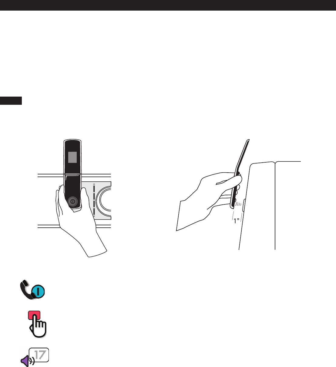
Kenmore Connect™ System
HOLD
NOTE:
PUSH
LISTEN
®
NOTE:
Using the Kenmore Connect™ System
BEFORE CALLING FOR SERVICE
TROUBLESHOOTING GUIDE
Problem Possible Cause Solutions
*CHECK VENT is
blinking
Dryer will not turn on
Dryer does not heat
NOTE:
Greasy or dirty spots on
clothes
Excess static in clothes
after drying
Drying time is not
consistent

BEFORECALLINGFORSERVICE(continued)
Problem Possible Cause Solutions
Clothes take too long to
dry
NOTE:
Clothes are wrinkled
Clothes are shrinking
TROUBLESHOOTING GUIDE
31
BEFORECALLINGFORSERVICE(continued)
TROUBLESHOOTING GUIDE
Problem Possible Cause Solutions
Display shows error
code: tE1 or tE2
Lint on clothes

32
Kenmore Limited Warranty
®
This warranty covers only defects in material and workmanship. Sears will NOT pay for:
Disclaimer of implied warranties; limitation of remedies
WARRANTY
