Kenmore Power Miser 153 320390 Ht 30 Gal Users Manual
153320490HT 153320490HT KENMORE POWER MISER 12+ ELECTRIC WATER HEATER - Manuals and Guides 99010364 View the owners manual for your KENMORE POWER MISER 12+ ELECTRIC WATER HEATER #153320490HT. Home:Plumbing Parts:Kenmore Parts:Kenmore POWER MISER 12+ ELECTRIC WATER HEATER Manual
KENMORE Water heater, Electric Manual 99010364 KENMORE Water heater, Electric Owner's Manual, KENMORE Water heater, Electric installation guides
153.37.0391HT 30 GAL. to the manual b09c8fd6-0daf-4299-bd23-a15203bbbfac
2015-01-24
: Kenmore Kenmore-Power-Miser-153-320390-Ht-30-Gal-Users-Manual-328466 kenmore-power-miser-153-320390-ht-30-gal-users-manual-328466 kenmore pdf
Open the PDF directly: View PDF ![]() .
.
Page Count: 28
Owners
Manual
FOR POTABLEWATER
HEATING ONLY
NOT SUITABLEFOR
SPACEHEATING
Model No.
153.320390 HT 30 Gal.
153.37.0391HT 30 Gal.
153.320490 HT 40 Gal.
153.320491 HT 40 Gal.
153.320590 HT 50 Gal.
153.320591 HT 50 Gal.
153.320690 HT 66 Gal.
153.320691 HT 66 GaL
153.320890 HT 82 Gal.
153.320891 HT 82 Gal.
Caution:
Read and Follow
All Safety Rules and
Operating Instructions
Before First Use of
This Product.
Savethis Manualfor Future Reference.
P_OWER MISER TM IO+
ELECTRIC
WATER HEATER
•Safety Instructions
•Installation
•Operation
• Care and Maintenance
• Troubleshooting
• Parts List
GAMA certification appTiesto all residential electric water heaters with
capacities of 20 to 120 Gallons. Input rating of 12 Kw or less at a voltage
no greater than 250 V.
_I,WARNING
READ THE GENERAL SAFETY SECTION BEGINNING ON INSIDE COVER
AND THEN THIS ENTIRE MANUAL BEFORE INSTALLING OR OPERAT-
ING TH S WATER HEATER.
Sears, Roebuck and Co., Hoffman Estates, IL 60179 U.S.A.
Safety Precautions
I _,WARNING 1
Improper installation, adjustment, alteration, service or I
maintenance can causeDEATH, SERIOUS BODILY INJUR_,|
OR PROPERTY DAMAGE. Refer to this manual for assis-|
tance or consultyour local SearsServiceCenter for further|
information. |
AWARNING
At the time of manufacturethis water heaterwasprovidedwith
a combinationtemperature-pressuresreliefvalvecertifiedby a
nationallyrecognizedte_tinglaboratorythat maintains periodic
inspectionof productionof listed equipmentor materials,as
meeting the requirementsfor ReliefValvesand AutomaticGas
ShutoffDevicesfor Hot Water SupplySystems,and the latest
editionof ANSI Z21.22and the coderequirementsof ASME.
replaced the valvemustmeet the requimnientsof localcedes,
butnot lessthan a combinationtemperatur_andpressurere ef
valvecertifiedasmeeting the requirementsfor ReliefValvesend
AutomaticGasShutoffDevicesfor Hot Water SupplySystems,
ANSI Z21.22by a nationally recognizedtestinglaboratorythat
maintains periodic inspec_onof productionof listedequipment
or materials.
The valvemust be markedwith a maximum setpressurenut
to exceed the marked hydrostaticworking pressureof the
water heater (150 IbsJsq.in.) and a dischargecapacitynut
lessthan the water heater inputrate asshownon the model
ratingplate. (Electric heaters- watts dividedby 1000x 3415
equalBTU/Hr. rate.)
Yourlocaljurisdictionalauthority,whilemandatingthe useof a
temperature-pressurerelief valvecomplyingwith ANSI Z21.22
andASME,mayrequirea valvemodeldifferentfromthe onefur-
nishedwiththe waterheater.
Compliancewith suchlocalrequirementsmust be satisfiedby
the installeror enduserof the water heaterwith a locallypre-
scribedtemperature-pressurerelief valveinstalledin the desig-
nated openingin the water heater in placeof the factoryfur-
nishedvalve.
Forsafeoperationofthe water heater,the reliefvalvemust nut
beremovedfromit'sdesignatedopeningor plugged.
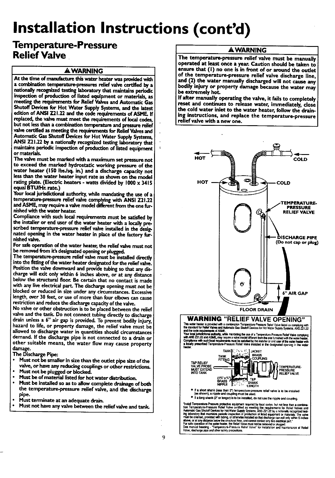
Thetemperature-pressurereliefvalvemust be installeddirectly
intothefittingof the waterheaterdesignatedforthe reliefvalve.
Positionthe valvedownwardandprovidetubingsothat any dis-
chargewill exit onlywithin 6 inchesabove,or at any distance
belowthe structuralfloor.Be certainthat no contactis made
withanyliveelectricalpart.The dischargeopeningmustnot be
blockedor reducedin sizeunderany circumstances.Excessive
length,over30 feet, or useof more than four elbowscancause
restrictionand reducethe dischargecapacityof thevalve.
No valveor otherobstructionisto he placedbetweenthe relief
valveand the tank. Do nut connecttubing directlyto discharge
drainunlessa 6"air gapisprovided.Topreventbodilyinjury,haz-
ardto life,or propertydamage,the reliefvalvemustbeallowed
to dischargewaterinquantitiesshouldcircumstancesdemand.If
the dischargepipeisnot connectedto a drainor othersuitable
means, the water flow may cause property
damage.
The DischargePipe:
• Mustnut besmallerinsizethan the outlet pipesizeofthe
valve,or haveany reducing couplingsor other restrictions.
Mustnot be pluggedor blocked.
Must be of material listedfor hotwater distribution.
Mustbe installedsoas to allowcomplete drainageof beth
the temperature-pressurerelief valve,and the discharge
pipe.
Mustterminate at an adequatedrain.
Mustnot haveany valvebetweenthe reliefvalveand tank.
AWARNING
HAZARD OF ELECTRICAL SHOCK! Before removing
any access panels or servicing the water heater, make
sure the electrical supp.lyto the water heater is turned
"OFF". Failure to do this could result in DEATH, SERI-
OUS BOD LY INJURY,OR PROPERTY DAMAGE.
_iWARNING
HOTTER WATER CAN SCALD: Water heaters are
intended to produce hot water. Water heated to a tem-
_eratore which will satisfy space heating, clotheswashing,
dish washing, and other sanitizing needs can scald and
_ermanently injure you upon contact. Some people are
more likely to be permanently injured by hot water than
others. These includethe elderly, children, the infirm, or
physically/mentally handicapped. If anyone using hot
water in your home fits into one of these groups or if
there is a local code or state law requiring a certain tem-
perature water at the hot water tap, then you must take
specialprecautions. In addition to usingthe lowest possi-
ble temperature setting that satisfies your hot water
needs, a means suchas a mixing valve, shallbe used at
the hot water taps used by these people or at the water
heater. Mixing valvesare availableat plumbing supplyor
hardware stores. Follow manufacturers instructions for
installation of the valves.Beforechangingthe factory set-
ting on the thermostat, read the "Temperature
Regulation"sectionin this manual.
AWARNING
WATER HEATERS EQUIPPED FOR ONE VOLTAGE
ONLY: This water heater is equippedfor onetype voltage
only.Checkthe rating plate near the bottom accesspanel
for the correct voltage. DO_NOT.use.tJ_s_water heater
with any voltage other than the one shownon the model
rating plate. Failure to use the correc_mltage can cause
problems which can result in DEATH, SERIOUS BODILY
INJURY, OR PROPERTY DAMAGE. If you h_ve any ques-
tions or doubtsconsultyour electric company,
-_WARNING
INSULATING JACKETS:-When installing-an external
water heater insulation jacket on an electric water
heater:
a. DO NOT coverthe temperature-pressure relief valve.
b. DO NOT put insulation over the accesscoversor any
access areas.
c. DO NOT cover or remove operating instructions,and
safety related warning labelsand materials affixed to the
water heater.
AWARNIN._G ]
Do not usethis applianceif any part of it has been under|
water, An electrical short or malfunction couldoccur.The |
water heater shouldbe replaced. I
ACAUTION
WATER HEATERS EVENTUALLY LEAK: Installation of
the water heater must be accomplishedin sucha manner
that if the tank or anyconnectionsshouldleak,the flowof
water will not causedamageto the structure. When such
locations cannot be avoided, a suitable drain pan should
be installed under the water heater. Drain pansare avail-
able at your local Sears Store. Sucha drain pan must be
piped to an adequate drain. Under no circumstances is
the manufacturer or Sears to be held liable for any water
damage in connectionwith thiswater heater.
2
Table of Contents
Safety Precautions ...............................................................................................................................................2
Table of Contents ................................................................................................................................................3
Introduction ..............................................................................................................................................................4
Product Specifications ..................................................................................................................................4
Preparing for the New Installation .............................................................................................4
Materials and Basic Tools Needed ...............................................................................................5
Materials Needed ...................................................................................................................................................................... 5
Basic Tools ................................................................................................................................................................................ 5
Installation Instructions ........................................................................................................................6-15
Removing the Old Water Heater......[ .......................................................................................................... .............................. 6
Facts to Consider About the Location ........................... [............................................................................. .-............................. 7
Facts to iConsider About the Convertible Lower Hement .......................................................................................................... 7
Water Piping ............................................................................................................................................................................. 8
Temperature-Pressure Relief Valve............................................................................................................................................. 9
Filling the Water Heater .......................................................................................................................................................... 10
Converting the Lower Hement .......................................................................................................................................... 10-12
Wiring Diagrams .................................................................................................................................................................... 13
Wiring .................................................................................................................................................................................... 14
Installation Checklist .............................................................................................................................................................. 15
Service and Adjustment ......................................................................................................................16-20
Temperature Regulation.......................................................................................................................................................... 16
Thermostats ............................................................................................................................................................................ 16
Thermostat Settings ................................................................................................................................................................ 16
Thermostat Adjustment .......................................................................................................................................................... 16
Temperature-Pressure Relief Valve Operation .......................................................................................................................... 17
Draining ................................................................................................................................................................................. 17
Element Cleaning and Replacement .................................................................................................................................. 18-20
Drain Valve Washer Replacement ........................................................................................................................................... 20
Service ....................................................................................................................... 20
Troubleshooting Guide ...................................................................................................:....................21-24
Start Up Conditions ............................................................................................................................................................... 21
Thermal Expansion ............................................................................................................................................................... 21
Strange Sounds ..................................................................................................................................................................... 21
Operational Conditions ..................................................................................................................................................... 22-23
Rumbling Noise .................................................................................................................................................................... 22
High Temperature Shut Off System ...................................................................................................................................... 22
Not Enough or No Hot Water .............................................................................................................................................. 23
Water is Too Hot .................................................................................................................................................................. 23
Indicator Light ...................................................................................................................................................................... 23
Leakage Checkpoints .............................................................................................................................................................. 24
Parts Order List...............................................................................................................................................26-27
Warranty ........................................................................................................................................................................28
Introduction
Thank You for purchasinga Sears water heater.
Properly installed and maintained, it should give you years of
trouble free service. If you should decide that you want the new
water heater professionally installed, contact the local Sears
Service Center or any Sears store. They will arrange for prompt,
quality installation by Sears authorized contractors.
Abbreviations Found In This Instruction Manual
U.L.-Underwriters Laboratories, 333 Pfingsten Rd.,
Northbrook, IL 60062
National ElectricalCode-This publication is available from your
local government or public library or electric company or by
writing to U.L. above.
A.N.S.I.-American National Standards Institute
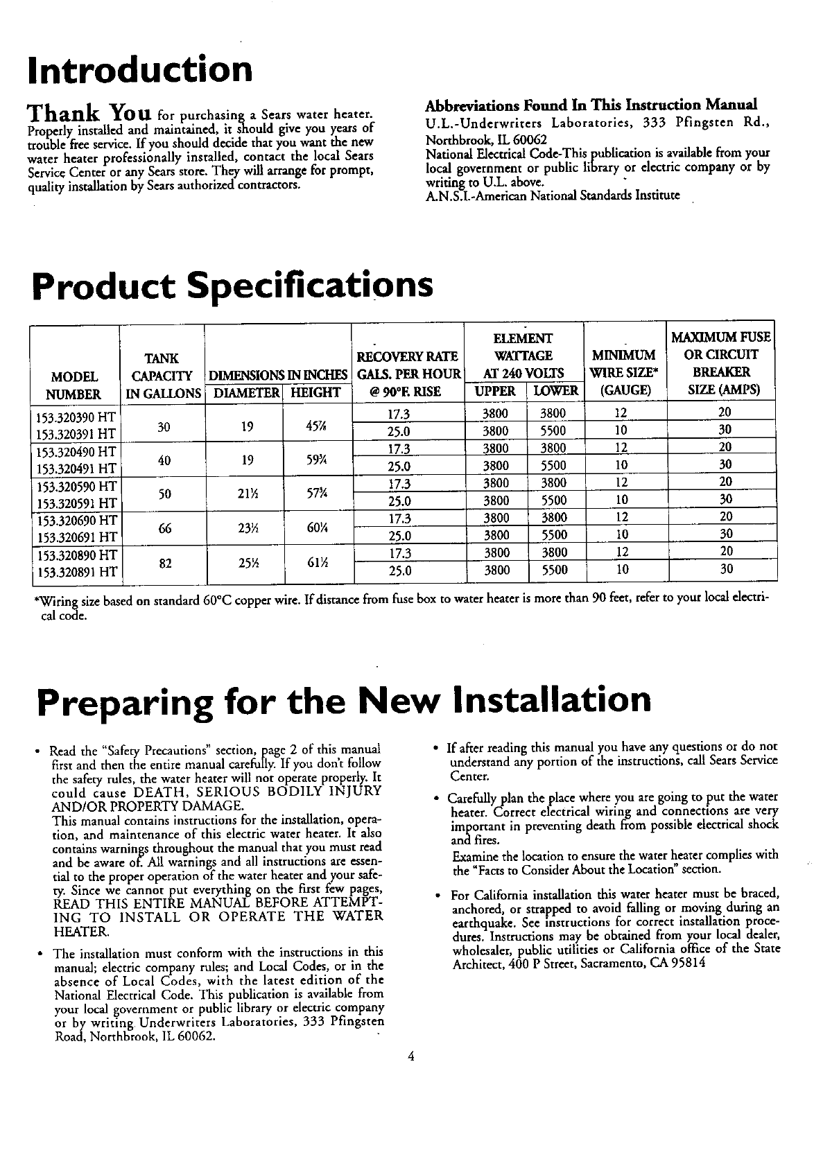
Product Specifications
MODEL
NUMBER
153.320390HT
153.320391HT
153.320490HT
153.320491HT
!53.320590HT
153.320591HT
153.320690HT
153.320691HT
153.320890HT
153.320891HT
TANK
CAPACITY
IN GALLONS
30
40
5O
66
82
DIMENSIONSININCHES
DIAMETER HEIGHT
19 45X
19 59¾
21½ 57_
23½ 60¼
25½ 61½
RECOVERYRATE
GALS. PERHOUR
@90°E RISE
17.3
25.0
17.3
25.0
17.3
25.0
17.3
25.0
17.3
25.0
WATYAGE
AT 24O VOLTS
UPPER LOWER
3800 3800
3800 5500
3800 3800
3800 5500
3800 3800
3800 5500
3800 3800
3800 5500
3800 3800
3800 5500
MIS UM
WIRE SIZE*
(GAUGE)
12
10
12
10
12
10
12
10
12
10
MAXIMUM FUSE
OR CIRCUIT
BREAKER
SIZE (AMPS)
20
30
20
30
20
30
2O
30
20
30
*Wiring size based on standard 60°C copper wire. If disrancefrom fuse box to water heater is more than 90 feet, refer to your local electri-
cal code.
Preparing for the New Installation
•Read the "Safety Precautions" section, page 2 of this,manuai
first and then the entire manual carefully. If you dont follow
the safety rules, the water heater will not operate properly. It
could cause DEATH, SERIOUS BODILY INJURY
AND/OR PROPERTY DAMAGE.
This manual contains instructions for the installation, opera-
tion, and maintenance of this electric water heater. It also
contains warnings throughout the manual that you must read
and be aware of. All warnings and all instructions are essen-
tial to the proper operation of the water heater and your safe-
ty. Since we cannot put everything on the first few pages,
READ THIS ENTIRE MANUAL BEFORE ATTEMPT-
ING TO INSTALL OR OPERATE THE WATER
HEATER.
•The installation must conform with the instructions in this
manual; electric company rules; and Local Codes, or in the
absence of Local Codes, with the latest edition of the
National Electrical Code. This publication is available from
your local government or public library or electric company
or by writing Underwriters Laboratories, 333 Pfingsten
Road, Northbrook, IL 60062.
•If after reading this manual you have any questions or do not
understand any portion of the instructions, call Sears Service
Center.
• Carefully plan the place where you are going to put the water
heater. Correct electrical wiring and connections are very
important in preventing death from possible electrical shock
and fires.
Examine the location to ensure the water heater complies with
u- . *t ,
the Facts to ConsLder About the Locanon sectmn.
•For California installation this water heater must be braced,
anchored, or strapped to avoid falling or moving during an
earthquake. See instructions for correct installation proce-
dures. Instructions may be obtained from your local dealer,
wholesaler, public utilities or California office of the State
Architect, 400 P Street, Sacramento, CA 95814
Materials and Basic Tools Needed
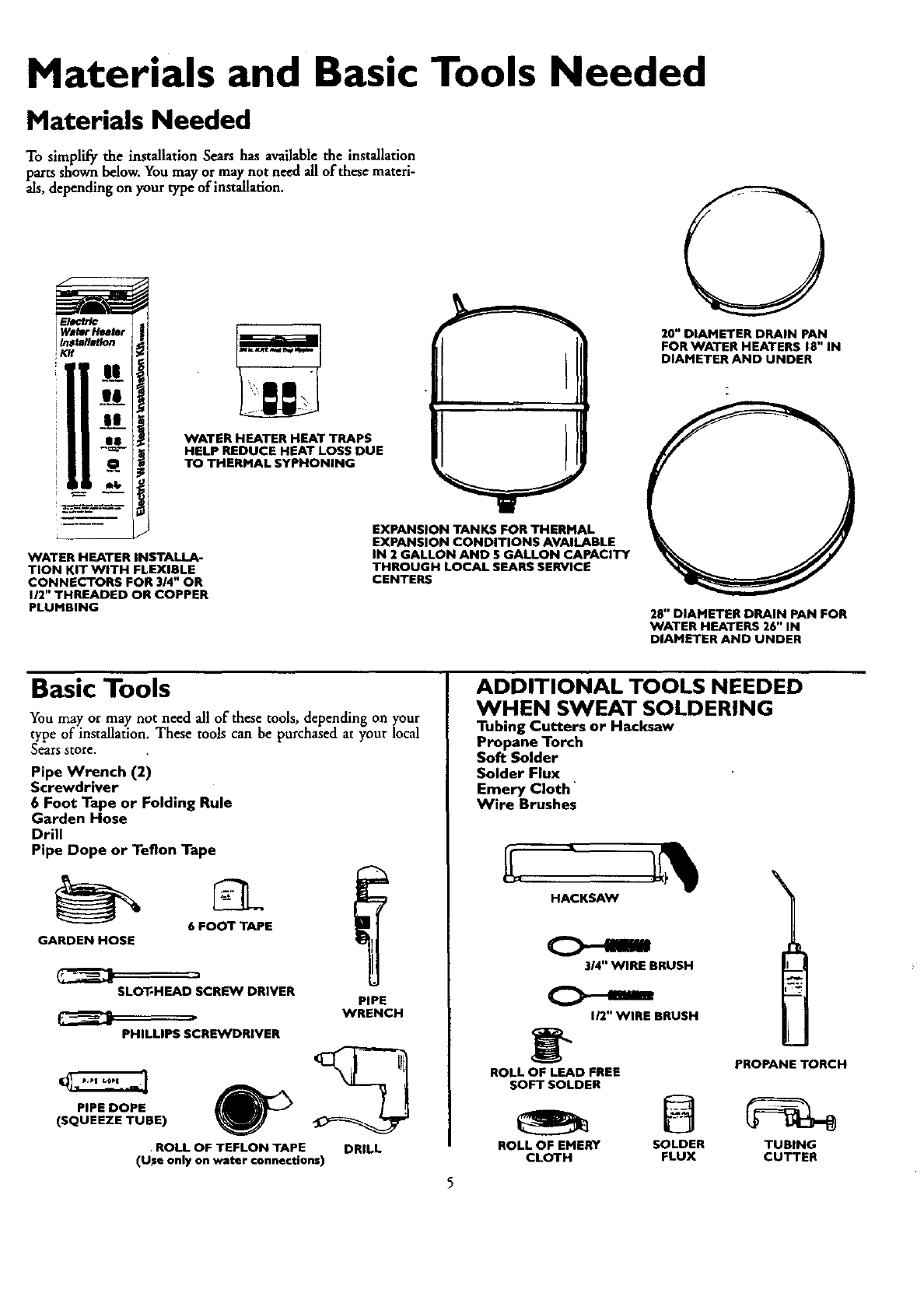
Materials Needed
To simplify the installation Sears has available the installation
parts shown below. You may or may not need all of these materi-
als, depending on your type of installation.
!K
WATER HEATER INSTALLA-
TION KIT WITH FLEXIBLE
CONNECTORS FOR 3/4" OR
112"THREADED OR COPPER
PLUMBING
WATER HEATER HEAT TRAPS
HELP REDUCE HEAT LOSS DUE
TO THERMAL SYPHONING
.,, ,.
EXPANSION TANKS FOR THERMAL
EXPANSION CONDITIONS AVAILABLE
IN 2 GALLON AND $ GALLON CAPACITY
THROUGH LOCAL SEARS SERVICE
CENTERS
20" DIAMETER DRAIN PAN
FOR WATER HEATERS 18" IN
DIAMETER AND UNDER
28" DIAMETER DRAIN PAN FOR
WATER HEATERS 26" IN
DIAMETER AND UNDER
Basic Tools
You may or may not need all of these tools, depending on your
type of installation. These tools can be purchased at your local
Sears store.
Pipe Wrench (2)
Screwdriver
6 Foot Tape or Folding Rule
Garden Hose
Drill
Pipe Dope or Teflon Tape
6 FOOT TAPE
GARDEN HOSE
SLOT-HEAD SCREW DRIVER
PHILLIPS SCREWDRIVER
PIPE DOPE
(SQUEEZE TUBE)
PIPE
WRENCH
•ROLL OF TEFLON TAPE
(U_e only on water connections) DRILL
ADDITIONAL TOOLS NEEDED
WHEN SWEAT SOLDERING
Tubing Cutters or Hacksaw
Propane Torch
Soft Solder
Solder Flux
Emery Cloth
Wire Brushes
BRUSH
112"WIRE BRUSH
PROPANE TORCH
ROLL OF LEAD FREE
SOFT SOLDER
ROLL OF EMERY SOLDER TUBING
CLOTH FLUX CUTTER
Installation Instructions
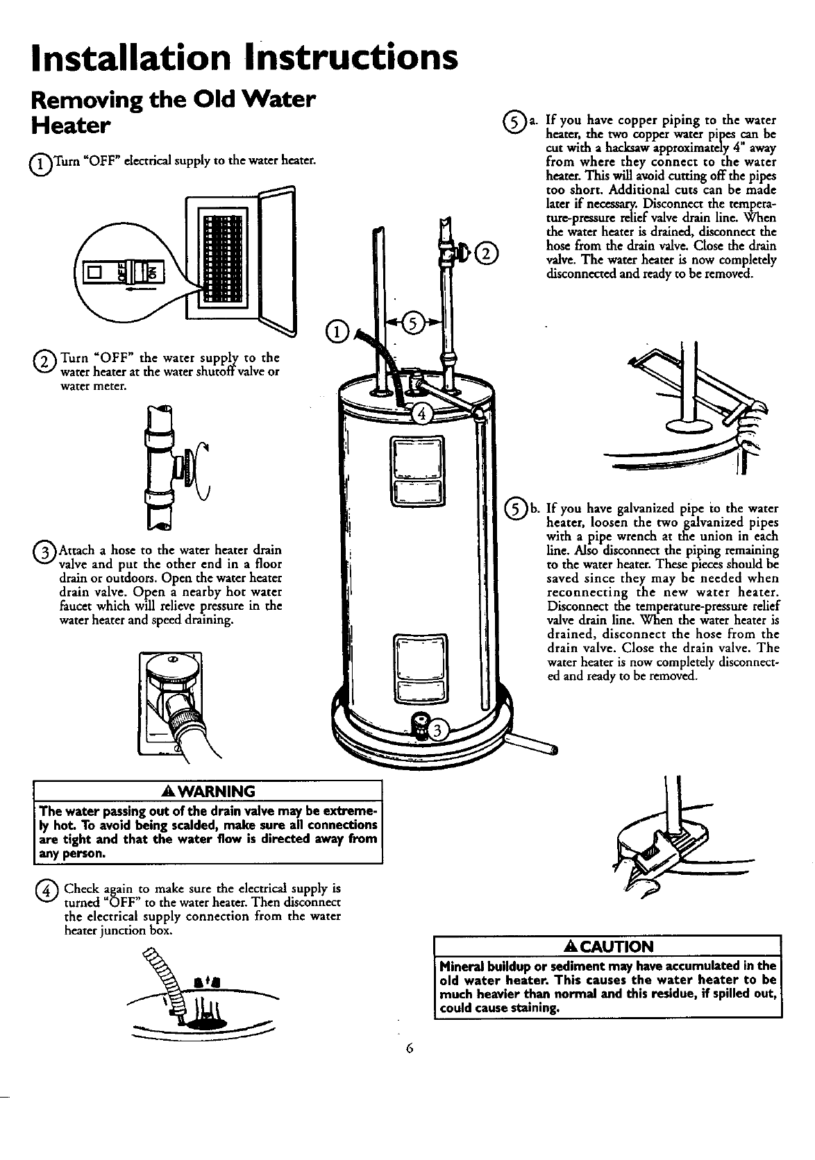
Removing the Old Water
Heater
Turn "OFF" electrical supply to the water heater.
Turn "OFF" the water supply to the
water heater at the water shutoffvalve or
water meter.
Attach ahose to the water heater drain
valve and put the other end in afloor
drain or outdoors. Open the water heater
drain valve. Open anearby hot water
faucet which will relieve pressure in the
water heater and speed draining.
AWARNING 1
The water passingo_alve may be extreme- I
ly hot. To avoid being scalded, mal_. sure all connectionsJ
are tight and that the water flow msdirected away from
any person, j
a. If you have copper piping to the water
heater, the two copper water pipes can be
cut with ahacksaw approximately 4 away
from where they connect to the water
heater. This will amid cutting off the pipes
too short. Additional cuts can be made
later if necessary. Disconnect the tempera-
ture-pressure relief valve drain line. When
the water heater is drained, disconnect the
hose from the drain valve. Close the drain
valve. The water heater is now completely
disconnected and ready to be removed.
Qb. you galvanized pipe water
If have to the
heater, loosen the two galvanized pipes
with apipe wrench at the union in each
line. Also disconnect the piping remaining
to the water heater. These pieces should be
saved since they may be needed when
reconnecting the new water heater.
Disconnect the temperature-pressure relief
valve drain line. When the water heater is
drained, disconnect the hose from the
drain valve. Close the drain valve. The
water heater is now completely disconnect-
ed and ready to be removed.
Q Check make sure the electrical supply isagain ,to
turned OFF to the water heater. Then disconnect
the electrical supply connection from the water
heater junction box.
ACAUTION ]
Mineral buildup or sediment may haveaccumulated inthe I
old water heater. This causes the water heater to be
much heavier than normal and this residue, if spilledout,
couldcausestaining. ]
6
Installation Instructions (cont'd)
Facts to Consider About the Facts to Consider About The
Location Convertible Lower Element
You should carefully choose an indoor location for the new
water heater, because the placement is a very important consid-
eration for the safety of the occupants in the building and for
the most economical use of the appliance. This water heater is
not intended for outdoor installation.
Whether replacing an old water heater or putting the water
heater in a new location, the following critical points must be
observed.
•The location selected should be indoors as .close to and as
centralized with the water piping system as possible. This
water heater, as well as all water heaters, will'eventually leak.
Do not install without adequate drainage provisions where
water flow will cause damage.
ACAUTION
WATER HEATERS EVENTUALLY LEAK: Installation of
the water heater must be accomplished in suchamanner
that if the tank or any connectionsshouldleak, the flow of
water will not causedamage to the structure. When such
locations cannot he avoided, a suitable drain pan should
be installed under the water heater. Drain pansare avail-
able at your local Sears stores. Such a drain pan must be
piped to an adequate drain. Under no circumstances is
the manufacturer or Sears to be held liable for any water
damagein connectionwith this water heater.
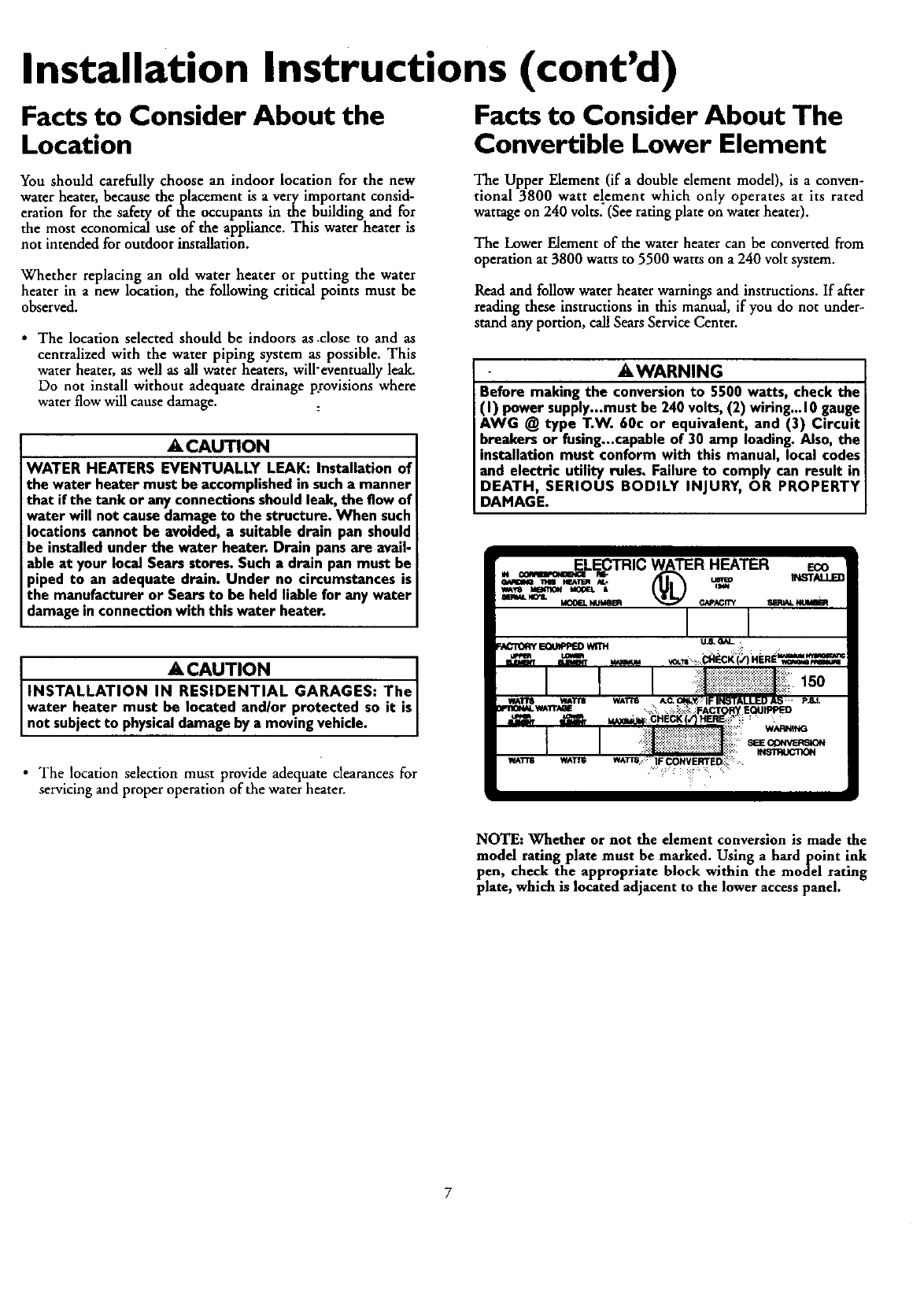
The Upper Element (if a double element model), is aconven-
tional 3800 watt el.ement which only operates at its rated
wattage on 240 volts, (See rating plate on water heater).
The Lower Element of the water heater can be converted from
operation at 3800 watts to 5500 watts on a 240 volt system.
Read and follow water heater warnings and instructions. If after
reading these instructions in this manual, if you do not under-
stand any portion, call Sears Service Center.
AWARNING
Before making the conversionto 5500 watts, check the
(I) power supply...mustbe 240 volts, (2) wiring...10gauge
AWG @ type T.W. 60c or equivalent, and (3) Circuit
breakers or fusing...capableof 30 amp loading.Also, the
installation must conform with this manual, local codes
and electric utility rules. Failure to comply can result in
DEATH, SERIOUS BODILY INJURY, OR PROPERTY
DAMAGE.
ACAUTION J
INSTALLATION IN RESIDENTIAL GARAGES." TheJ
water heater must be located and/or protected so it is
not subjectto physicaldamage by a mov ng veh c e.
•The location selection must provide adequate clearances for
servicing and proper operation of the water heater.
NOTE: Whether or not the element conversion is made the
model rating plate must he ma_ked. Using ahardpoint ink
pen, check the appropriate block within the model rating
plate, which is located adjacent to the lower access panel.
Installation Instructions (cont'd)
Water Piping
_WARNING
HOTTER WATER CAN SCALD: Water heaters are
intended to produce hot water. Water heated to atem-
perature which will satisfyspaceheating, clotheswashing,
dish washing, and other sanitizing needs can scald and
permanently injure you upon contact. Some people are
more likely to be permanently injured by hot water than
others. These include the eldedy, children, the infirm, or
physically/mentally handicapped. If anyone using hot
water in your home fits into one of these groups or if
there is a local code or state law requiring a certain tem-
perature water at the hot water tap, then you must take
specialprecautions. In addition to usingthe lowest possi-
ble temperature setting that satisfies your hot water
needs, a means such as a mixing valve, shall be used at
the hot water taps used by these people or at the water
heater. Mixing valvesare available at plumbing supplyor
hardware stores. Follow manufacturers instructions for
installation of the valves.Before changingthe factory set-
ting on the thermostat, read the "Temperature
Regulation"section in this manual.
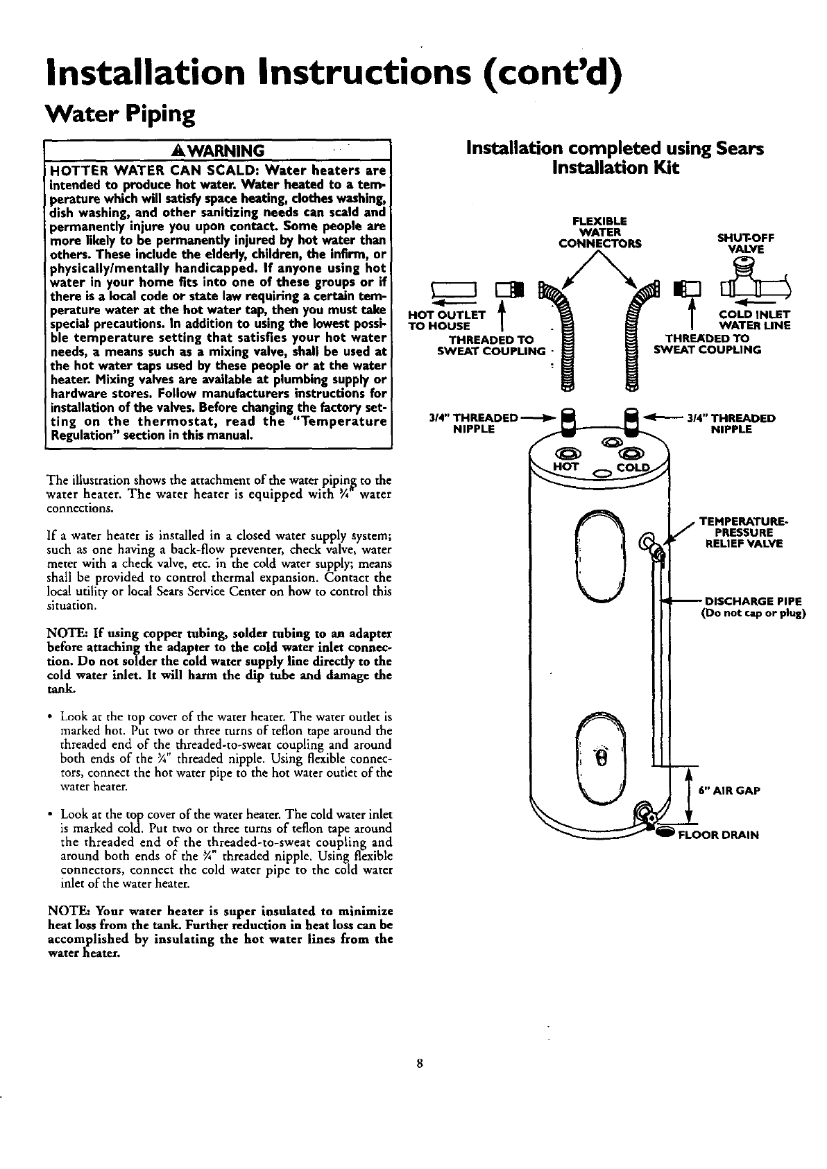
The illustration shows the attachment of the water piping to the
water heater. The water heater is equipped with ¾ water
connections.
If awater heater is installed in aclosed water supply system;
such as one having aback-flow preventer, check valve, water
meter with acheck valve, etc. in the cold water supply; means
shall be provided to control thermal expansion. Contact the
local utility or local Sears Service Center on how to control this
situation.
NOTE: If using copper tubing, solder tubing to an adapter
before attaching the adapter to the cold water inlet connec-
tion. Do not solder the cold water supply line directly to the
cold water inlet. It will harm the dip tube and damage the
tank.
•Look at the top cover of the water heater. The water outlet is
marked hot. Put two or three turns of teflon tape around the
threaded end of the threaded-to-sweat coupling and around
both ends of the %" threaded nipple. Using flexible connec-
tors, connect the hot water pipe to the hot water outlet of the
water heater.
•Look at the top cover of the water heater. The cold water inlet
is marked cold. Put two or three turns of teflon tape around
the threaded end of the threaded-to-sweat coupling and
around both ends of the %" threaded nipple. Using flexible
connectors, connect the cold water pipe to the cold water
inlet of the water heater.
Installation completed using Sears
Installation Kit
FLEXIBLE
WATER SHUT-OFF
CONNECTORS VALVE
HOT OUTLET _COLD INLET
TO HOUSE WATER LINE
THREADED TO THREADED TO
SWEAT COUPLING " SWEAT COUPLING
TEMPERATURE-
PRESSURE
RELIEF VALVE
-- DISCHARGE PIPE
(Do not cap or plug)
6" AIR GAP
iJ FLOOR DRAIN
NOTE: Your water heater is super insulated to minimize
heat loss from the tank. Further reduction in heat loss can be
accomplished by insulating the hot water lines from the
water heater.
Installation Instructions (cont'd)
Temperature-Pressure
Relief Valve
_WARNING
At the time of manufacturethiswater heaterwasprovidedwith
a combinatien temperamre_resseresretief valveearthed by a
nationallyrecognizedtestinglaboratorythat maintainsperiodic
inspectionof productionof li_.. equipmentor materials,as
meetingthe _luirements for RehefValvesandAutomaticGas
ShutoffDevicesfor Hot Water SupplySystems,andthe latest
editionof ANSI 7.21.22and rite coderequirementsof ASME.If
replaced,the valvemustmeet the requirementsof localcedes,
butnot lessthana combinationtemperatureandpressurerelief
valvecertifiedasmeetingthe requirementsfor ReliofValvesand
AutomaticGasShutoff Devicesfor Hot Water SupplySysten_,
ANSI Z21.22by a nationallyrecognizedtestinglaboratorythat
mdnt_ per;oakim4_'t_ of preduct_of,stedequ_=nt
ormaterial_
The valvemust be markedwith a maximum setpressurenot
to exceed the marked hydrostaticworking pressureof the
water heater (150 IbsJsq.in.) and a dischargecapEt'm/nut
lessthan the water heater inputrate as shownon the model
rating plate. (Electric heaters- watts dividedby 1000x 3415
equalBTU/Hr. rate.)
YourlocaljurirKl_ anthorit_ whilemandatingthe useof a
temperature-pressurerelief valvecomplyingwith ANSI Z21.22
andASME,mayrequirea valvemodeldifferentfromthe onefur-
nishedwiththe waterhe,_er.
Compliancewith suchlocalrequirementsmust be satisfiedby
the installeror enduserof the water heaterwith a locallypre-
scribedtemperature-pressurereliefvalveinstalledin the desig-
natedopeningin the water heaterin placeof the factoryfur-
nishedvalve.
For safeoperationof the water heater,the reliefvalvemustnot
beremovedfromit'sdesignatedopeningorplugged.
The temperature-pressurereliefvalvemustbe installeddirectly
intothe fittingofthe water heaterdesignatedfur the reliefvabe.
Positionthe valvedownwardandprovidetubingsothat anydis-
chargewill exit onlywithin 6 inchesabove,or at any distance
belowthe structuralfloor.Be certainthat no contactismade
withanyliveelectricalpart.The dischargeopeningmust not be
blockedor reducedin sizeunderany circumstances.Excessive
length,over30 feet, or useof more than fourelbowscan cause
restrictionand reducethe dischargecapacityofthe valve.
No valveor other obstructionisto be placedbetweenthe relief
valveandthe tank.Do not connecttubingdirectlyto discharge
drainunlessa 6" air gapis provided.To preventbodilyinjury,
hazardto life, or property damage,the relief valve must be
allowedto dischargewater in quantitiesshouldcircumstances
demand.If the dischargepipe is not connectedto adrainor
other suitable means, the water flow may causeproperty
damage.
The DischargePipe:
• Mustnnt be smallerin sizethanthe outlet pipe sizeof the
valve,or haveanyreducingcouplingsor other restrictions.
•Mustnot be pluggedor blocked.
•Mustbeof material listedfor hotwater distribution.
• Mustbe installedso as to allow complete drainageof buth
the temperature-pressurerelief valve,and the discharge
pipe.
Mustterminate at an adequatedrain.
[_Mustnot haveanyvalvebetween the relief valveandtank.
AWARNING
The temperature-pressure relief valve must be manually
operated at least once a year. Caution shouldbe taken to I
ensure that (I) no one is in from:of or around the outlet
of the temperature-pressure relief valve discharge line,
md (2) the water manuallydischargedwill not causeany
)odily iniuP/or property damage becausethe water may
)e extremely hot.
If after manually operating the valve,it failsto completely
reset and continues to release water, immediately, close
the cold water inlet to the water heater, followthe drain-
ing instructions, and replace the temperature-pressure
relief valve with a new one.
HOT COLD
HOT
.TEMPERATURE-
PRESSURE
RELIEF VALVE
(Do not €_o or plug)
6" AIR GAP
FLOOR DRAIN
T&P RELIEF
INTO TANK
TEMPERATURE-
PRESSURE
RELIEF VALVE
9
Installation Instructions (cont'd)
Filling the Water Heater
To fill the water heater with water:
Close the seater heater drain valve by turning the handle to
the right (clockwise). The drain valve is on the lower front of
the water heater.
Open the cold water supply valve to the water heater.
NOTE: The cold water supply valve must be left open
when the water heater is in use.
•To insure complete filling of the tank, allow air to exit by
opening the nearest hot water faucet. Allow water to run
until aconstant flow is obtained. This will let air out of the
water heater and the piping.
ACAUTION
Never use thiswater heater unlessit is completelyfull of
water. To prevent damage to the tank and heating ele-
ment, the tank must be filled with water. Water must
flow from the hot water faucet before turning "ON"
power.
Check all new water piping for leaks. Repair as needed.
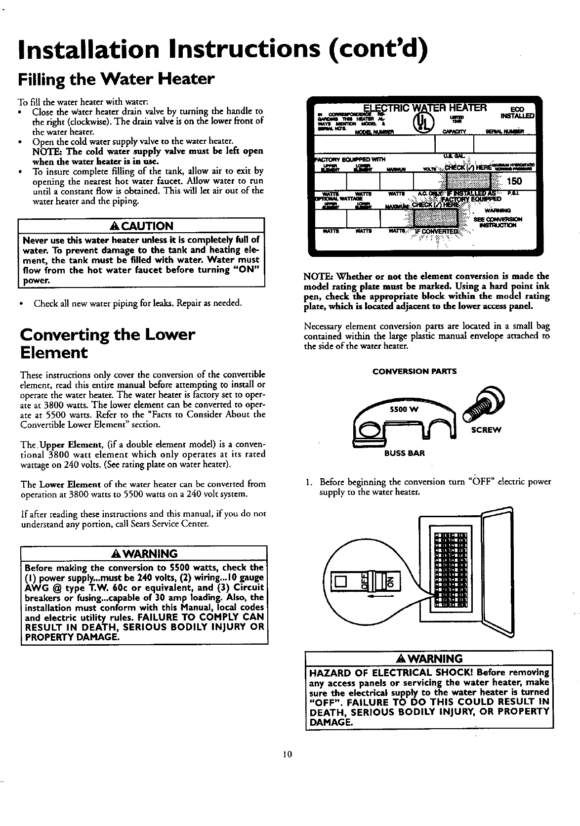
NOTE: Whether or not the element conversion is made the
model rating plate must be marked. Using a hard point ink
pen, check the appropriate block within the model rating
plate, which is located adjacent to the lower access panel.
Converting the Lower
Element
Necessary element conversion parts are located in asmall bag
contained within the large plastic manual envelope attached to
the side of the water heater.
These instructions only cover the conversion of the convertible
dement, read this entire manual before attempting to install or
operate the water heater. The water heater is factory set to oper-
ate at 3800 watts. The lower element can be converted to oper-
ate at 5500 watts. Refer to the Facts to Consider About the
Convertible Lower Element" section.
TheUpper Element, (if a double element model) is a conven-
tional 3800 watt element which only operates at its rated
wattage on 240 volts. (See rating plate on water heater).
The Lower Element of the water heater can be converted from
operation at 3800 watts to 5500 watts on a 240 volt system.
CONVERSION PARers
BUSS BAR
1. Before beginning the conversion turn "OFF" electric power
supply to the water heater.
if after reading these instructions and this manual, if you do not
understand any portion, call Sears Service Center.
AWARNING
Before making the conversion to 5500 watts, check the
(I) power supply...mustbe 240 volts, (2) wiring...10 gauge
AWG @ type T.W. 60c or equivalent, and (3) Circuit
breakers or fusing...capableof 30 amp loading. Also, the
installation must conform with this Manual, local codes
and electric utility rules. FAILURE TO COMPLY CAN
RESULT IN DEATH, SERIOUS BODILY INJURY OR
PROPERTY DAMAGE.
AWARNING
HAZARD OF ELECTRICAL SHOCKI Before removing
any access panels or servicing the water heater, make
sure the electrical supplyto the water heater is turned
"OFF". FAILURE TO DO THIS COULD RESULT IN
DEATH, SERIOUS BODILY INJURY, OR PROPERTY
DAMAGE.
10
Installation Instructions (cont'd)
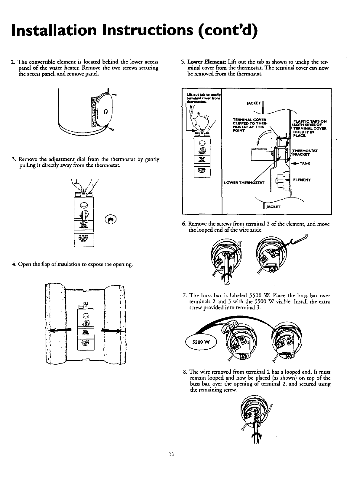
2. The convertible dement is located behind the lower access
panel of the water heater. Remove the two screws securing
the access panel, and remove panel.
5. Lower Element: LiE out the tab as shown to undip the ter-
minal cover from the thermostat. The terminal cover can now
be removed from the thermostat.
3. Remove the adjustment dial from the thermostat by gently
pulling it directly away from the thermostat.
4. Open the flap of insulation to expose the opening.
;! i
m
L_ oul _b Io uncl¥
tlrmlr_l covlr fro_
)ACKET
TERMINAL COYER
CLIPPED TO TILER-
Hos'rAT AT THIS
POINT
!LOWER THERMOSTAT
PLASTIC TABS ON
TERMINAL COVER
HOLD IT IN
PLACE,
6. Remove the screws from terminal 2 of the element, and move
the looped end of the wire aside.
7. The buss bar is labeled 5500 W. Place the buss bar over
terminals 2 and 3 with the 5500 W visible. Install the extra
screw provided into terminal 3.
5500W
8. The wire removed from terminal 2 has alooped end. It must
remain looped and now be placed (as shown) on top of the
buss bar, over the opening of terminal 2, and secured using
the remaining screw.
11
Installation Instructions (cont'd)
Converting the Lower
Element (cont'd)
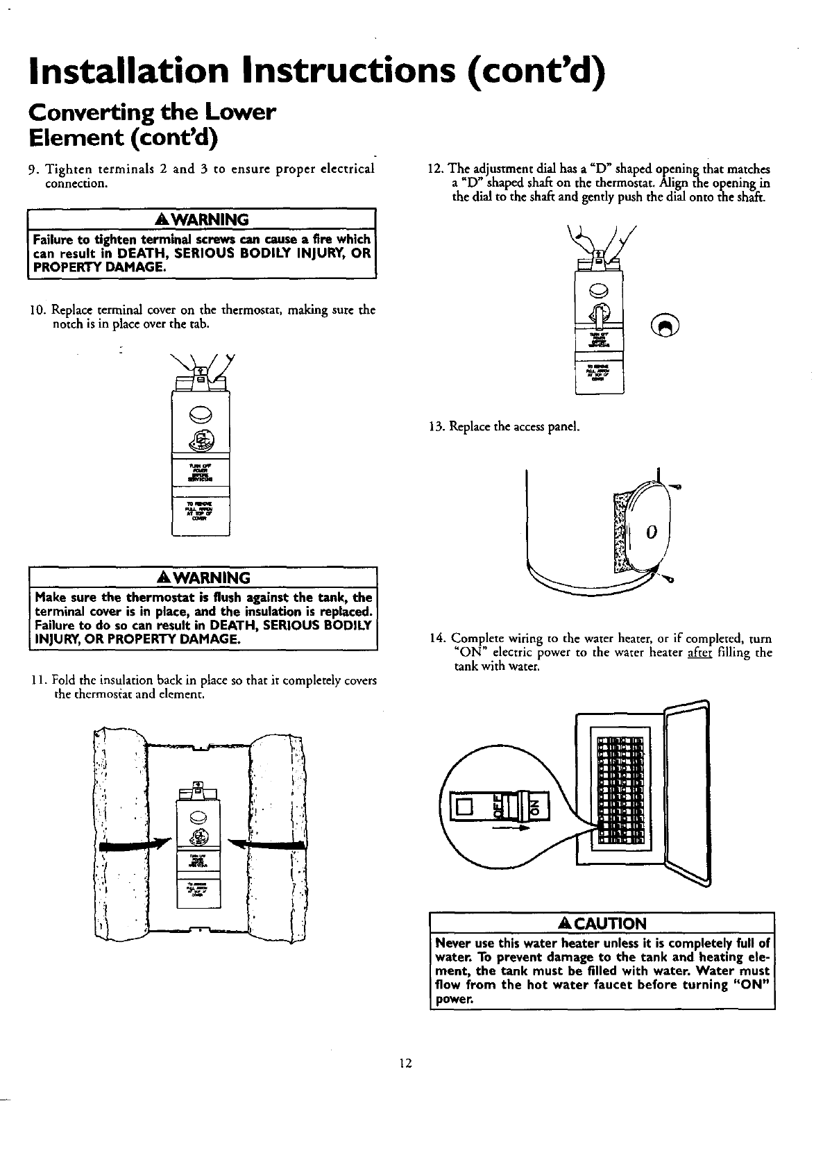
9. Tighten terminals 2 and 3 to ensure proper electrical
couNec_on.
I AWARNING
Failure to tighten terminal screwscan cause afire which I
can result in DEATH, SERIOUS BODILY INJURY, OR I
PROPERTY DAMAGE.
10. Replace terminal cover on the thermostat, making sure the
notch is in place over the tab.
12. The adjustment dial has a"D" shaped opening that matches
a"D" shaped shah on the thermostat. Align the opening in
the dial to the shaft and gently push the dial onto the sh_ft.
13. Replace the accesspanel.
t AWARNING I
Make sure the therm_against the tank, the I
terminal cover is in ' "'"-place,and the insulation is replaced.
Failure to do so can result in DEATH, SERIOUS BODILY
INJURY,OR PROPERTY DAMAGE.
11. Fold the insulation back in place so that it completely covers
the thermostat and element.
/
x--
:'I_; _v
14, Complete wiring to the water heater, or if completed, turn
"ON" electric power to the water heater after filling the
tank with water.
IACAUTION 1
Never use this water heater unlessit is completelyfull of|
water. To prevent damage to the tank and heating ele-|
ment, the tank must be filled with water. Water musti
flow from the hot water faucet before turning "ON"|
power. |
12
Installation Instructions (cont'd)
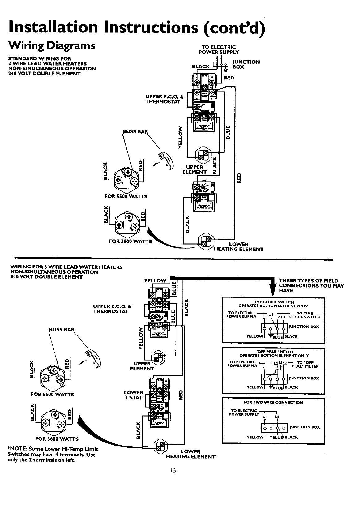
Wiring Diagrams
STANDARD WIRING FOR
2 WIRE LEAD WATER HEATERS
NON-SIMULTANEOUS OPERATION
240 VOLT DOUBLE ELEMENT
TO ELECTRIC
POWER SUPPLY
BLACK
RED
UPPER E.C.O. &
THERMOSTAT
IUEEBA O
.J
.J
tU
)-
FOR 5500 WATTS
UPPER
ELEMENT @
FOR 3000 WATTS LOWER
_EATING ELEMENT
WIRING FOR 3 WIRE LEAD WATER HEATERS
NON-SIMULTANEOUS OPERATION
240 VOLT DOUBLE ELEMENT
UPPER E.C.O. &
THERMOSTAT
FOR 5500 WATTS
FOR 3800 WATTS
*NOTE: Some Lower Hi-Temp Limit
Switches may have 4 terminals. Use
only the 2 terminals on left.
o
.J
.J
uJ
)-
ELEMENT
LOWER
T'STAT
LOWER
HEATING ELEMENT
13
_HREE TYPES OF FIELD
CONNECTIONS YOU MAY
HAVE
TIME CLOCK SWITCH
OPERATES BO'i-I_M ELEMENT ONLY
TOELECTRIC _ L2 _ TOTIME
POWERSUPPLY LI L2 L2 CLOCKSW_TCH
JO _@BI_I _NCTION BOX
YELL CK
"OFF PEAK" METER
OPERATES BOTTOM ELEMENT ONLY
TOELECTRIC _L2LIL2 -4. TO"OFF
POWER SUPPLY LI _PEAK" METER
_JUNCTION BOX
YELL LACK
FOR TWO WIRE CONNECTION
TO ELECTRIC .,..r--.- 1
POWER SUPPLY LI L2
JOW_BLANCTION BOX
YELL CK
Installation Instructions (cont'd)
Wiring
J_CAUTION I
Never use this water heater unlessit is completely full of
water. To prevent damage to the tank and heating ele- ]
ment, the tank must be filled with water. Water must
flow from the hot water faucet before turning on power.
You must provide all wiring of the proper size outside of the
water heater. You must obey local codes and electric company
requirements when you install this wiring.
If you are not familiar with electric codes and practices, or if you
have any doubt, even the slightest doubt, in your ability to con-
nect the wiring to this water heater, obtain the service of a com-
petent e ectrician. Contact your Searssalesperson to arrange for
aprofessional electrician.
C. Flexible metal conduit or flexible metallic tubing shall be
permitted for grounding if all the following conditions are
met[
1. The length in any ground return path does not exceed
6 feet.
2. The circuit conductors contained therein are protected
by overcurrent devices rated at 20 amperesor less.
3. The conduit or tubing is terminated in fittings
approvedfor grounding.
For complete grounding details and all allowable exceptions,
refer to the latest edition of the National Electrical Code.
4. A standard ½" conduit opening has been made in the water
heater junction box for the conduit connection.
AWARNING
WATER HEATERS EQUIPPED FOR ONE VOLTAGE
ONLY: This water heater is equippedfor one type voltage
only.Check the rating plate near the bottom accesspanel
for the correct voltage. DO NOT use this water heater
with any voltage other than the one shown on the model
rating plate. Failure to use the correct voltage can cause
problems which can result in DEATH, SERIOUS BODILY
INJURY,OR PROPERTY DAMAGE. If you have any ques-
tions or doubtsconsultyour electric company.
A CAUTION
If wiring from your fuse box or circuit breaker box was
aluminum for your old water heater, replace it with cop-
per wire. If you wishto reuse the existingaluminum wire,
have the connection at the water heater made by a com-
petent electrician. Contact your Sears salesperson to
arrange for a professionalelectrician.
1. Provide away to easily shut off the electric power when work-
ing on the water heater. This could be with a circuit breaker
or fuse block in the entrance box or a separate disconnect
switch.
2. Install and connect acircuit directly from the main fuse or
circuit breaker box. This circuit must be the right size and
have its own fuse or circuit breaker. Refer to the chart in the
"Product Specifications" section for the correct size wire and
fuse or circuit breaker.
5. Wiring Diagrams (See Wiring Diagrams Section) have been
supplied showing the two most common types of connec-
tions between the water heater and the power supply. You cart
easily see which type connection you have by removing the
junction box cover on top of the water heater.
A, Two W'um Connection Diagrams: is the most common
requiring you to simply connect red to red, black to black,
and the ground wire to the green ground screw in the junc-
tion box of the water heater.
B. Three Wire Connection Diagram: is used when you are
connecting the water heater to power asupply that has a
Time Clock or Off Peak Meter. To make these connec-
tions refer to block 1 or 2 in this wiring diagram for the type
of system you have.
NOTE: If you have purchased a three wire connexion
water heater but you are not on a "Time Clock" or Off
Peak" meter and have a standard two wire connection
cower supply, simply follow the connection diagram in
lock 3. of the Three Wire Connection Diagram.
6. Use wire nuts and connect the power supply wiring to the
wires inside the water beater's junction.
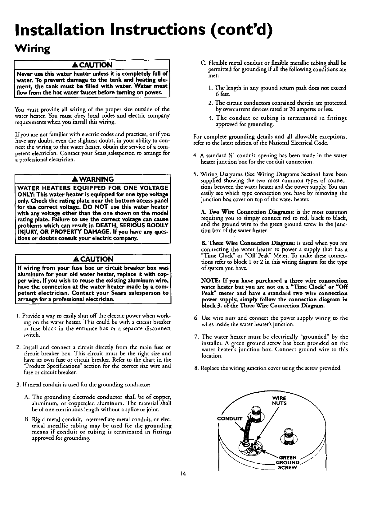
7. The water heater must be electrically "grounded" by the
installer. A _reen ground screw has been provided on the
water heater sjunction box. Connect ground wire to this
location.
8, Replace the wiring junction cover using the screw provided.
3. If metal conduit is used for the grounding conductor:
A. The grounding electrode conductor shall be of copper,
aluminum, or copperclad aluminum. The material shall
be of one continuous length without asplice or joint.
B. Rigid metal conduit, intermediate metal conduit, or elec-
trical metallic tubing may be used for the grounding
means if conduit or tubing is terminated in fittings
approved for grounding.
CONDUIT
GI
SCREW
14
Installation Instructions (cont'd)
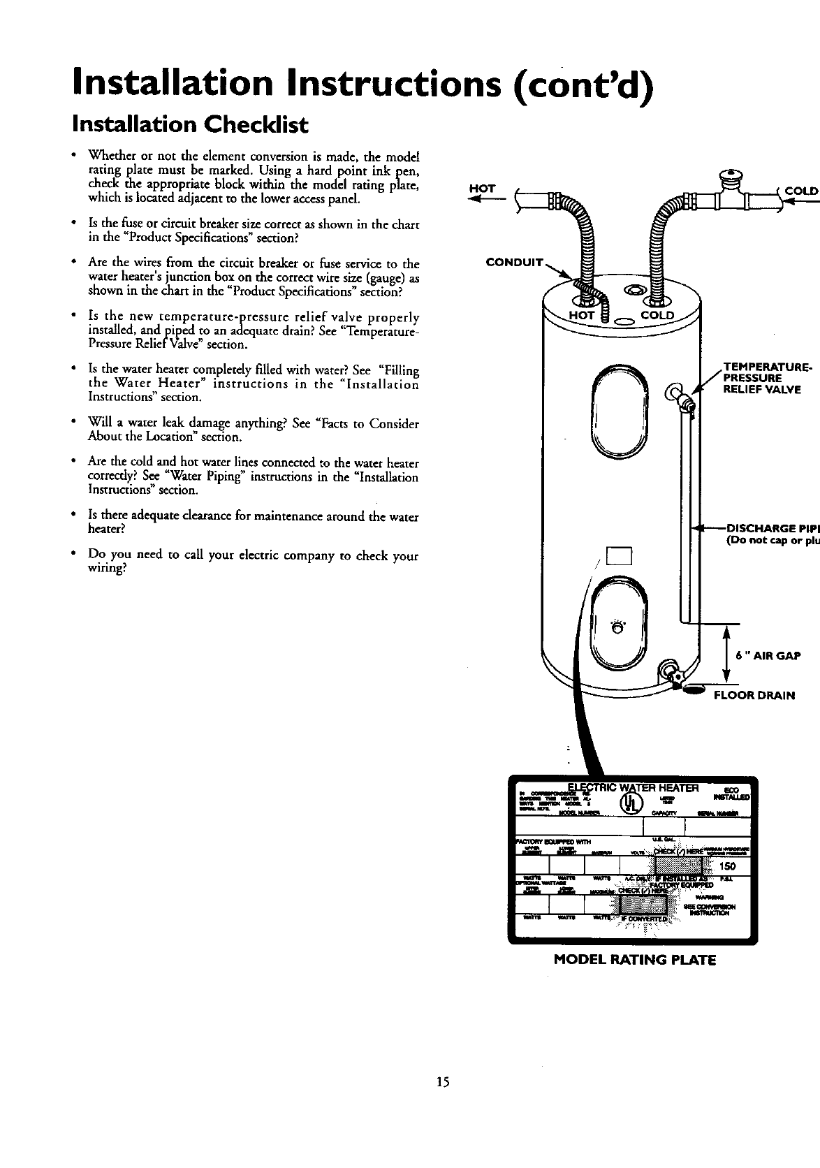
Installation Checklist
•Whether or not the element conversion is made, the model
rating plate must be marked. Using a hard point ink I_en,
check the appropriate block within the model rating plate,
which is located adjacent to the lower access panel.
•Is the fuse or circuit breaker size correct as shown in the chart
in the "ProductSpecifications" section?
• Are the wires from the circuit breaker or fuse service to the
water heater's junction box on the correct wire size (gauge) as
shown in the chart in the "Product Specifications" section?
Is the new temperature-pressure relief valve properly
installed, andpiped to an adequate drain? See "Temperature-
Pressure Relief Valve" section.
Is the water heater completely filled with water? See "Filling
the Water Heater" instructions in the "Installation
Instructions section.
•Will awater leak damage anything? See _Facts to Consider
About the Location" section.
• Are the cold and hot water lines connected to the water heater
cor_tly? See "Water Piping" instructions in the "Installation
Instructions sect on.
•Is there adequate clearance for maintenance around the water
heater?
•Do you need to call your electric company to check your
wiring?
HOT COLD
6"AIR GAP
FLOOR DRAIN
MODEL RATING PLATE
15
Service and Adjustment
Temperature Regulation
AWARNING
HOTTER WATER CAN SCALD: Water heaters are
intended to produce hot water. Water heated to a tem-
perature which will satisfyspaceheating, clothes washing,
dish washing, and other sanitizing needs can scald and
permanently injure you upon contact. Some people are
more likely to be permanently injured by hot water than
others. These include the elderly, children, the infirm, or
physicallylmentally handicapped. If anyone using hot
water in your home fits into one of these groups or d
there is a local code or state law requiring a certain tem-
perature water at the hot water tap, then you must take
specialprecautions. In addition to usingthe lowest possi-
ble temperature setting that satisfies your hot water
needs, a means such as a mixing valve, shall be used at
the hot water taps usedby these people or at the water
heater. Mixing valves are availableat plumbing supplyor
hardware stores. Follow manufacturers instructions for
installation of the valves.Before changingthe factory set-
ting on the thermostat, read the "Temperature
Regulation"sectionin this manual.
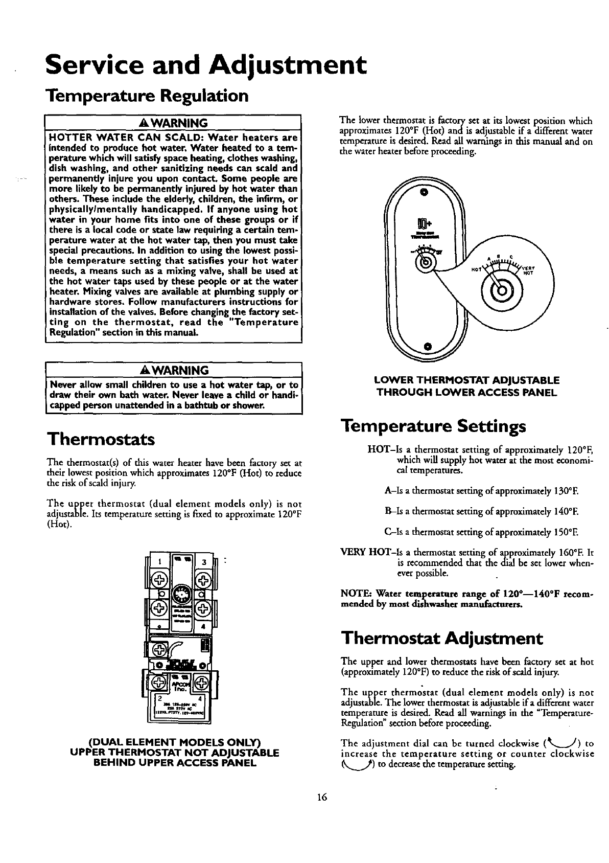
The lower thermostat is factory set at its lowest position which
approximates 120°F (Hot) andis adjustable if adifferent water
temperature is desired. Read all warnings in this manual and on
the water heater before proceeding.
IAWARNING ]
Never allow small children to use a hot water tap, or to
draw their own hath water. Never leave achild or handi-J
capped personunattended in abathtub or shower. ]
Thermostats
The thermostat(s) of this water heater have been factory set at
their lowest position which approximates 120°F (Hot) to reduce
the risk of scald injury,
The upper thermostat (dual element models only) is not
adjustable, Its temperature setting is fLxedto approximate 120°F
(Hot).
(DUAL ELEMENT MODELS ONLY)
UPPER THERMOSTAT NOT ADJUSTABLE
BEHIND UPPER ACCESS PANEL
LOWER THERMOSTAT ADJUSTABLE
THROUGH LOWER ACCESS PANEL
Temperature Settings
HOT-Is athermostat setting of approximately 120°F,
which will supply hot water at the most economi-
cal temperatures.
A-Is a thermostat setting of approximately 130°E
B-Is a thermostat setting of approximately 140°E
C-Is a thermostat setting of approximately 150°E
VERY HOT-Is a thermostat setting of approximately 160°F. It
is recommended that the dial be set lower when-
ever possible.
NOTE: Water temperature range of 120°--140°F recom-
mended by most dishw_her manufacturers.
Thermostat Adjustment
The upper and lower thermostats have been factory set at hot
(approximately 120°F) to reduce the risk of scald injury.
The upper thermostat (dual element models only) is not
adjustable.The lower thermostat is adjustableira different water
temperature is desired. Read all warnings in the Temperature-
Regulation"section before proceeding.
The adjustment dial can be turned clockwise (_._..fl) to
increase the temperature setting or counter clockwise
_..._.._) to decrease the temperature setting.
16
Service and Adjustment (cont'd)
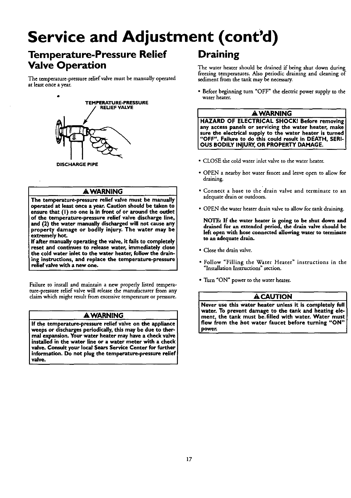
Temperature-Pressure Relief
Valve Operation
The temperature-pressure relief valve must be manually operated
at least once a year.
TEMPERATURE-PRESSURE
RELIEF VALVE
Draining
The water heater should be drained if being shut down during
freezing temperatures. Also periodic draining and cleaning of
sediment from the tank may be necessary.
•Before beginning turn "OFF" the electric power supply to the
water heater.
AWARNING
HAZARD OF ELECTRICAL SHOCK! Before removing I
any access panels or servicing the water heater, make
I sure the electrical supply to the water heater is turned I
IoOFFBo I: ; J°U I_d_-_td_MDAEATH' SER'I
DISCHARGE PIPE
AWARNING
The temperature-pressure relief valve must be manually
operated at least once a year. Caution shouldbe taken to
ensure that (I) no one is in front of or around the outlet
of the temperature-pressure relief valve discharge line,
and (2) the water manually dischargedwill not causeany
property damage or bodily injury. The water may be
extremely hot.
If after manuallyoperating the valve,it failsto completely
reset and continues to release water, immediately close
the cold water inlet to the water heater, followthe drain-
ing instructions, and replace the temperature-pressure
relief valve with a new one.
•CLOSE the cold water inlet valve to the water heater.
•OPEN anearby hot water faucet and leave open to allow for
draining.
• Connect ahose to the drain valve and terminate to an
adequatedrain or outdoors.
• OPEN the water heater drain valve to allow for rank draining.
NOTE: If the water heater is going to be shut down and
drained for an extended period, the drain valve should be
left open with hose connected allowing water to terminate
man adequate drain.
• Close the drain valve.
•Follow "Filling the W,,ater Heater" instructions in the
Installation Instructions section.
Failure to install and maintain a new properly listed tempera-
ture-pressure relief valve will release the manufacturer from any
claim which might result from excessive temperature or pressure.
AWARNING
If the temperature-pressure relief valve on the appliance
weeps or dischargesperiodically,this may be due to ther-
mal expansion.Your water heater may havea check valve
installed in the water line or a water meter with acheck
valve. Consult your local Sears ServiceCenter for further
information. Do not plug the temperature-pressure relief
valve.
• Turn "ON" power to the water heater.
ACAUTION
Never use this water heater unless it is completely full I
water. To prevent damage to the tank and heating ele- I
ment, the tank must be:filled with water. Water must I
flow from the hot water faucet before turning "ON"I
I-p°wer' I
17
Service and Adjustment (cont'd)
Element Cleaning/
Replacement
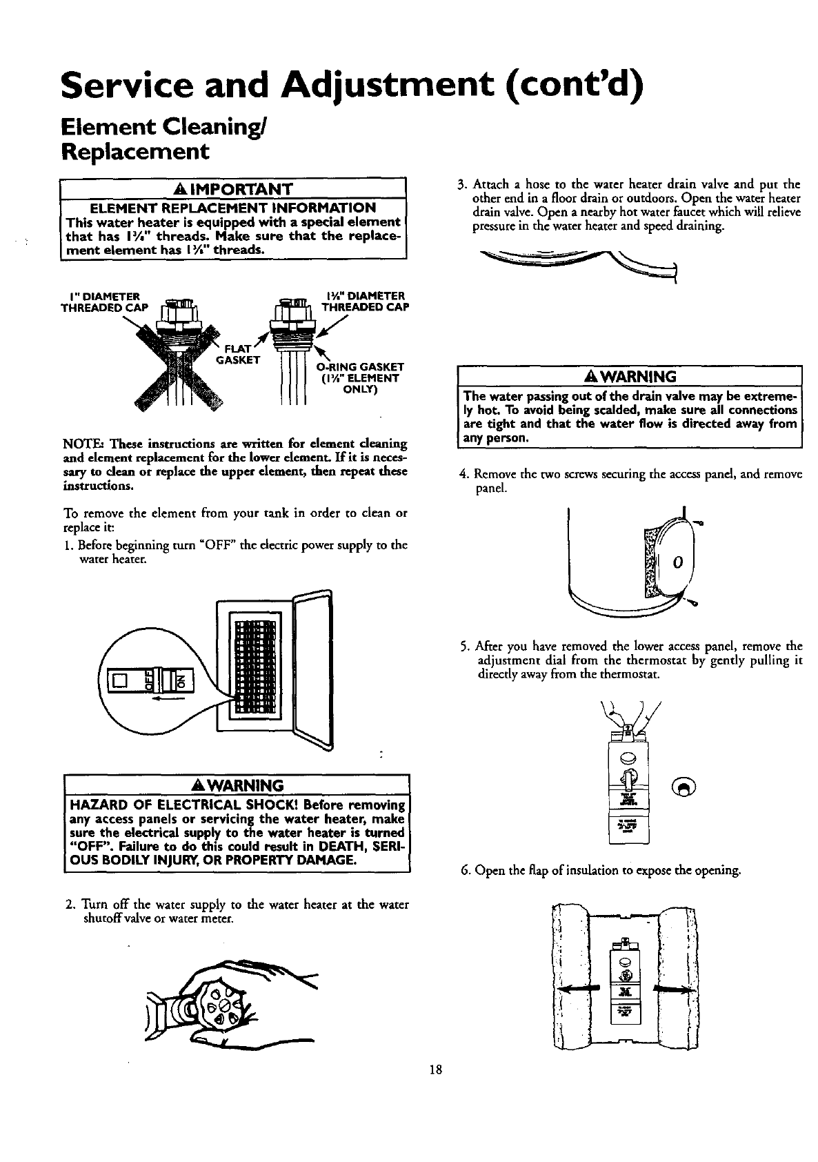
l A IMPORTANT I
ELEMENT REPLACEMENT INFORMATION I
This water heater is equipped with a special element
that has I%" threads. Make sure that the replace-
ment element has I_ threads.
I" DIAMETER lY*" DIAMETER
THREADED CAP THREADED CAP
3. Attach ahose to the water heater drain valve and put the
other end in a floor drain or outdoors. Open the water heater
drain valve. Open a nearby hot water faucet which will relieve
pressure in the water heater and speed draining.
O-RING GASKET
(1_" ELEMENT
ONLY)
NOTE." These instructions are written for element deanlng
and element replacement for the lower element. ][fit is neces-
sary to clean or replace the upper element, thee repeat these
instructions.
To remove the element from your tank in order to clean or
replace it:
1. Before beginning turn "OFF" the electric power supply to the
water heater.
AWARNING I
The water passingout of the drain valve may be extreme-
ly hot. To avoid beingscalded,make sure all connectionsI
are tight and that the water flow is directed away from
any person.
4. Remove the two screws securing the access panel, and remove
panel.
AWARNING
HAZARD OF ELECTRICAL SHOCK! Before removing I
any access panels or servicing the water heater, make
Isure the electrical suppl.yto the water heater is tumed I
"OFF". Failure to do thin could result in DEATH, SERI-I
I OUS BODILY INJURY,OR PROPERTY DAMAGE. I
2. Turn off the water supply to the water heater at the water
shutoffvalve or water meter.
18
5. After you have removed the lower access panel, remove the
adjustment dial from the thermostat by gently pulling it
directly away from the thermostat.
6. Open the flap of insulation to expose the opening.
. 14
Service and Adjustment (cont'd)
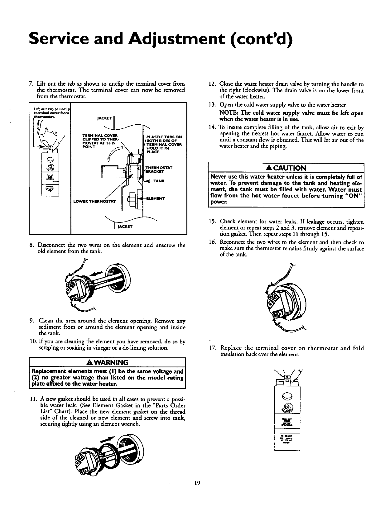
7. Lift out the tab as shown to unclip the terminal cover from
the thermostat. The terminal cover can now be removed
from the thermostat.
Lift out tab to u_ip
terminal (Awer from
_t
TERMINAL COVER
CLIPPED TO THER-
MOSTAT AT THIS
POINT
LOI_VERTHERHOSTAT
Z
PLASTIC TABS ON
rBOTH SIDES OF
TERMINAL COVER
HOLD IT IN
PLACL
THERMOSTAT
BRACKET
4[-- TANK
_LEMENT
8. Disconnect the two wires on the element and unscrew the
old element from the tank.
12. Close the water heater drain valve by turning the handle to
the right (clockwise). The drain valve is on the lower front
of the water heater.
13. Open the cold water supply valve to the water heater.
NOTE: The cold water supply valve must he left open
when the water heater is in use.
14. To insure complete filling of the tank, allow air to exit by
opening the nearest hot water faucet. Allow water to run
until a constant flow is obtained. This will let air out of the
water heater and the piping.
ACAUTION
Never use this water heater unlessit is completely full of
water. To prevent damage to the tank and heating ele-
ment, the tank must be filled with water. Water must
flow from the hot water faucet before'turning "ON"
power.
15. Check element for water leaks. If leakage occurs, tighten
element or repeat steps 2 and 3, remove element and reposi-
tion gasket. Then repeat steps 11 through 15.
16. Reconnect the two wires to the element and then check to
make sure the thermostat remains firmly against the surface
of the tank.
9. Clean the area around the element opening. Remove any
sediment from or around the element opening and inside
the tank.
10. If you are cleaning the element you have removed, do so by
scraping or soaking in vinegar or a de-liming solution.
A WARNING
Replacement elements must (I) be the same voltage and I
(2) no greater wattage than listed on the model rating
p ate affixed to the water heater,
11. A new gasket should be used in all cases to prevent apossi-
ble water leak. (See Element Gasket in the "Parts Order
List" Chart). Place the new element gasket on the thread
side of the cleaned or new element and screw into tank,
securing tighdy using an element wrench.
17. Replace the -terminal cover on thermostat and fold
insulation back over the element.
©
i
m_
ar .1_ a*
19
Service and Adjustment (cont'd)
Element Cleaning/
Replacement (cont'd)
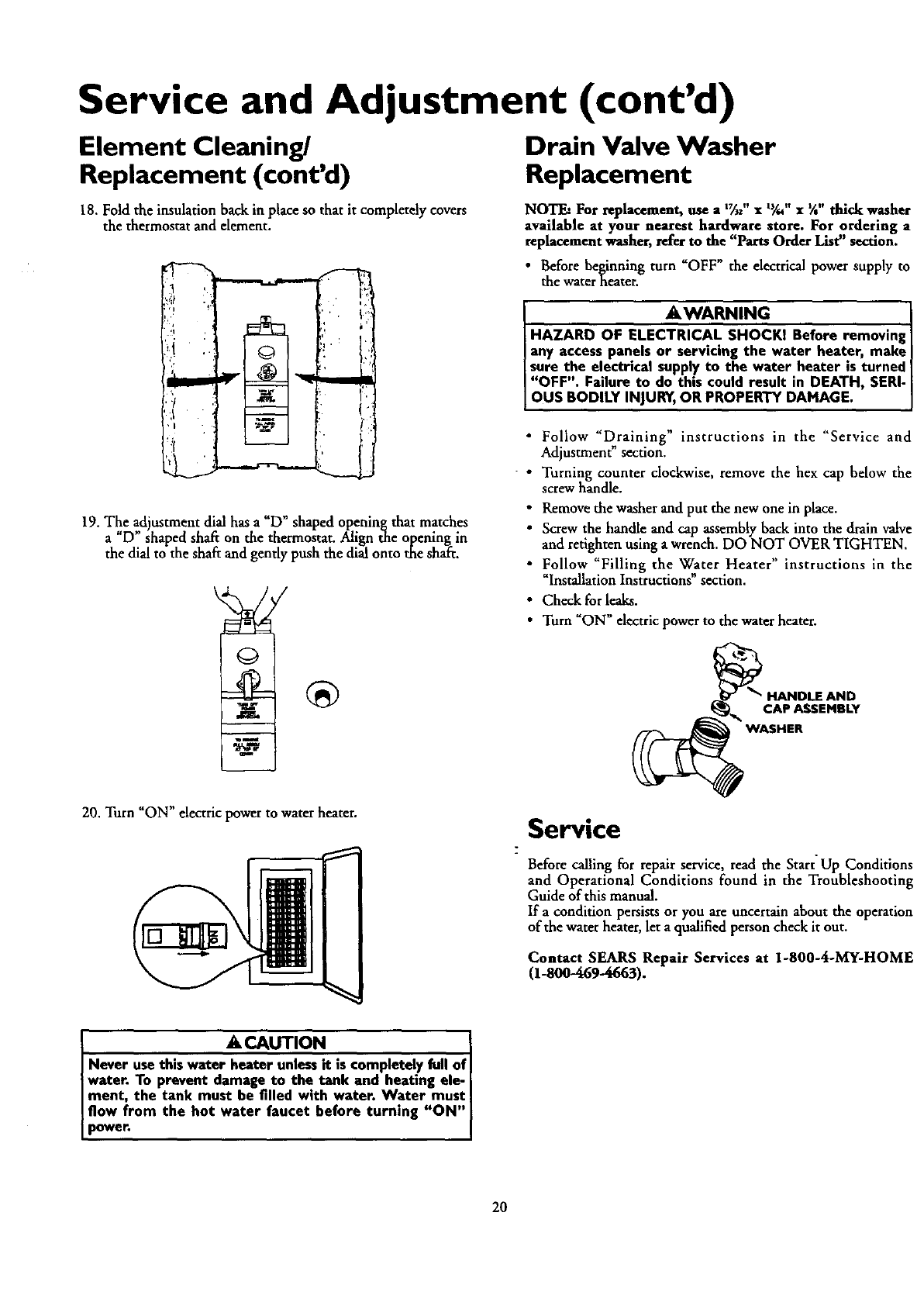
18. Fold the insulation back in place so that it completely covers
the thermostat and element.
l? I-:1
19. The adjustment dial hasa"D" shaped opening that matches
a"D" shaped shaft on the thermostat. Align the opening in
the dial to the shaft and gently push the dial onto the shaft.
Drain Valve Washer
Replacement
NOTE: For replacement, use a 'Tu"x t_/," •X" thick washer
available at your nearest hardware store. For ordering a
replacement washer, refer to the "Parts Order List" section.
•Before beginning turn "OFF" the electrical power supply to
the water heater.
AWARNING
HAZARD OF ELECTRICAL SHOCK1 Before removing
any access panels or servicing the water heater, make l
sure the electrical supply to the water heater is turned
"OFF". Failure to do this could result in DEATH, SERI-I
I OUS BODILY NJURY,OR PROPERTY DAMAGE.
•Follow _Draining" instructions in the "Service and
Adjustment" section.
•Turning counter clockwise, remove the hex cap below the
screw handle.
• Remove the washer and put the new one in place.
• Screw the handle and cap assembly back into the drain valve
and retighten using awrench. DO NOT OVER TIGHTEN.
•Follow _Filliog the Water Heater" instructions in the
_Installation Instructions section.
• Check for leaks.
•Turn "ON" electric power to the waterheater.
_HANDLE AND
CAP ASSEMBLY
_ _" WASHER
20. Turn "ON" electric power to water heater. Service
Before calling for repair service, read the Start Up Conditions
and Operational Conditions found in the Troubleshooting
Guide of this manual.
If acondition persists or you are uncertain about the operation
of the water heater, let aqualified person check it out.
Contact SEARS Repair Services at 1-800-4-MY-HOME
(1.-800-469-4663).
ACAUTION
Never usethis water heater unlessit is completely full of
water. To prevent damage to the tank and heating ele-
ment, the tank must be filled with water. Water must
flow from the hot water faucet before turning "ON"
_weh
20
Troubleshooting Guide
Start Up Conditions
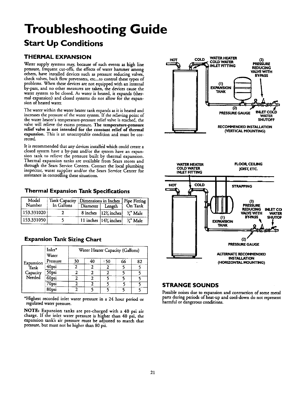
THERMAL EXPANSION
Water sup,ply systems may, because of such events as high line
pressure, frequent cut-offs, the effects of water hammer among
others, have installed devices such as pressure reducing valves,
check valves, back flow preventers, etc._to control these types of
problems. When these devices are not equipped with an internal
oy-pass, and no other measures are taken, the devices cause the
water system to be dosed. As water is heated, it expands (ther-
mal expansion) and closed systems do not allow for the expan-
sion of heated water.
The water within the water heater tank expands as it is heated and
increases the pressure of the water system. If the relieving point of
the water heater's temperature-pressure relief valve is rea_ed, the
valve will relieve the excess pressure. The temperature-pressure
relief valve is not intended for the constant relief of thermal
expansion. This is an unacceptable condition and must be cor-
rected.
It is recommended that any devices installed which could create a
dosed system have aby-pass and/or the system have an expan-
sion tank to relieve the pressure built by thermal expansion.
Thermal expansion tanks are available from Sears stores and
through the Sears Service Centers. Contact the local plumbing
inspector, water su_.plier and/or the Sears Service Center for
assistance in controlling these situations.
Thermal Expansion Tank Specifications
Model
Number
153.331020
153.331050
Tank Capacity
In Gallons
2
5
Dimensions in Inches
Diameter Length
8 inches 12_ inches
11 inches 14_ inches
Pipe Fitting
On Tank
_" Male
_" Male
HOT COLD
WATER HEA13ER
COLD WATER
INLET FITTING
HOT COLD
WATERHEATER 0)
•COLDWATER PRESSURE
INLETFn-rlNG REDUCING
VALVEWITH
BY-PASS
(1) 1
EXPANSION
TANK
(2)
PRESSUREGAUGE WATER
SHUTOFF
RECOMMENDED INSTALLATION
(VERTICAl. MOUNTING)
FLOOR,CEIUNG
joist, ETC.
STRAPPING
(i)
EXPANSION
o)
PRESSURE
REDUCING INLETCOL
VALYEWITH WATER
BY-PASS SHUTOFF
Expansion Tank Sizing Chart
Water Heater Capacity (Gallons)
Inlet*
Water
Pressure
40psi
50psi
60psi
70psi
80psi
30 J 40 :50 66 82
Expansion
Tank 2 I2 2 5 5
Capacity 2 2 2 5 5
Needed 2 2 555
225 5 5
25 5 5 5
*Highest recorded inlet water pressure in a 24 hour period or
regulated water pressure.
NOTE: Expansion tanks are pre-charged with a 40 psi air
charge. If the inlet water pressure is higher than 40 psi, the
expansion tank's air pressure must be adjusted to match that
pressure, but must not be higher than 80 psi.
PRESSUREGAUGE
ALTERNATE RECOMMENDED
INSTALLATION
(HORIZONTAL MOUNTING)
STRANGE SOUNDS
Possible noises due to expansion and contraction of some metal
parts during periods of heat-up and cool-down do not represent
harmful or dangerous conditions.
21

Troubleshooting Guide (cont'd)
Operational Conditions
RUMBLING NOISE
In some water areas, scale or mineral deposits will build up on
your heating elements. This buildup will cause a rumbling noise.
Follow _Element Cleaning/Replacement" instructions to dean
and replace the elements.
• Remove the two screws securing the access pand and remove
pand.
•Open the flap of insulation to expose the opening.
•Reset the high limit by pushing in the red button marked
"RESET _.
HIGH TEMPERATURE SHUT OFF SYSTEM
The water heater has a high limit shut off system with a reset
button located in the upper thermostat.
Follow the resetting instructions which refer to the high limit
behind the upper accesspanel.
NOTE: If your water heater is connected to an "Off Peak"
hi-limit on both the upper and lower thermostats. Follow
the instructions to reset the hi-limit behind the upper and
lower access panels.
RESET BUTTON
•Before beginning, turn "OFF" electrical power supply to the
waterheater. • Fold the insulation back in place so that it completely covers
the thermostat and element.
• Replace the access panel.
•Turn _ON _ electric power to the waterheater.
•&CAUTION 1
If the high hmit mus_n, call Sears Service|
Department to tlnd out why the highlimit turned "OFF" I
the electric power, j
AWARNING
HAZARD OF ELECTRICAL SHOCKt Before removing
any access panels or servicing the water heater, make
sure the electrical supplyto the water heater is turned t
1;OFFBc)_I_yr_N_U_, _ I_dEreI_tD_MDEGAT. H' SER'"I
22
Troubleshooting Guide (cont'd)
NOT ENOUGH OR NO HOT WATER
In a new installation, the water heater may not be properly
connected. Make sure the cold water supply valve is open.
Review and check piping installation. Make sure that the
cold water line is connected to the cold water inlet to the
water heater and the hot water line to the hot water outlet
on the water heater.
•Make sure the electrical supply to your water heater is
"ON'.
Check for loose or blown fuses in your water heater circuit.
Circuit breakers weaken with age and may not handle their
rated load and should be replaced.
Make certain the disconnect switch, if used, is in the "ON"
position.
Check to see the dectric service to your house has not been
interrupted. If this is the case, contact the electric company.
Are the thermostats set to the desired temperature? See
"Temperature Regulation" section.
If you had experienced very hot water and now no hot
water, the problem may be due to the high temperature shut
off system. See _High Temperature Shut Off System" in the
Troubleshooting Guide section.
During very cold weather, the incoming water will also be
colder and it will require a longer time to become heated.
The hot water usage may exceed the capacity of the water
heater. If so, wait for water heater to recoverafter abnormal
demand. Also examine pipes and faucets for possible water
leaks.
If you can not determine the problem, then call the Sears
Service Department.
WATER IS TOO HOT
Adjust the thermostat to a lower setting. See the "Temperature
Regulation"section.
23
Troubleshooting Guide (cont'd)
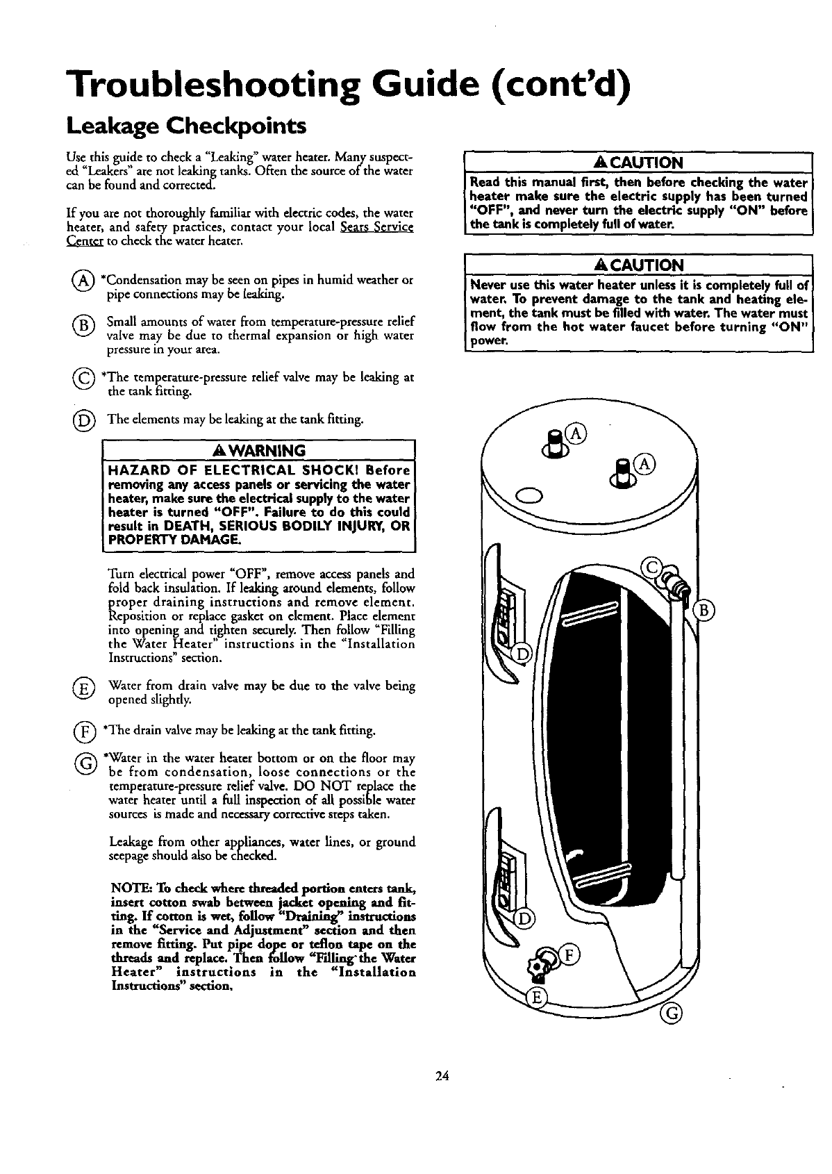
Leakage Checkpoints
Use this guide to check a"Leaking" water heater. Many suspect-
ed "Leakers" are not leaking tanks. Often the source of the water
can be found and corrected.
If you are not thoroughly familiar with electric codes, the water
heater, and safety practices, contact your local
Center to check the water heater.
(_) *Condensation may seen on pipes or
be in humid weather
pipe connections may be leaking.
(_) Small amounts of water from temperature-pressure relief
valve may be due to thermal expansion or high water
pressure in your area.
(_) *The relief valve be leaking at
temperature-pressure may
the tank fitting.
(_ The elements be leaking at the tank fitting.
may
_WARNING
HAZARD OF ELECTRICAL SHOCKI Before
removing any accesspanels or servicing the water
heater, make surethe electrical supplyto the water
heater is turned "OFF". Failure to do this could
result in DEATH, SERIOUS BODILY INJURY, OR
PROPERTY DAMAGE,
Turn electrical power "OFF", remove acems panels and
fold back insulation. If leaking around elements, follow
proper draining instructions and remove element.
Reposirion or replace gasket on element. Place element
into opening and t!,ghten securely. Then follow "Filling
the Water Heater instructions in the "Installation
Instructions section.
Water from drain valve be due to the valve being
may
opened slightly.
(_ *The drain valve may be leaking at the tank fitting.
(_ *Water in the water heater bottom or on the floor may
be from condensation, loose connections or the
temperature-pressurerelief valve. DO NOT replace the
water heater until afull inspection of all possible water
sources is made and necessary corrective steps taken.
Leakage from other appliances, water lines, or ground
seepage should also be checked.
NOTE: To check where threaded portion enters tank,
insert cotton swab hetween jacket opening and fit-
ting. If cotton is wet, follow "Draining" instructions
in the "Service and Adjustment" section end then
remove fitting. Put pipe dope or teflon tape on the
threads and replace..Then follow "Falling'the Water
Heater" instrucuons in the "Installation
Instructions" section,
&CAUTION [
Read this manual first, then before checking the water]
] heater make sure the electric supply has been turned
"OFF", and never turn the electric supply "ON" before
] the tank is completely full of water.
ACAUTION [
Never use this water heater unlessit is completely full of_
water, To prevent damage to the tank and heating ele-
I ment, the tank must be filled with water. The water must 1
] flow from the hot water faucet before turning "ON"
]power. ]
24

Notes
25
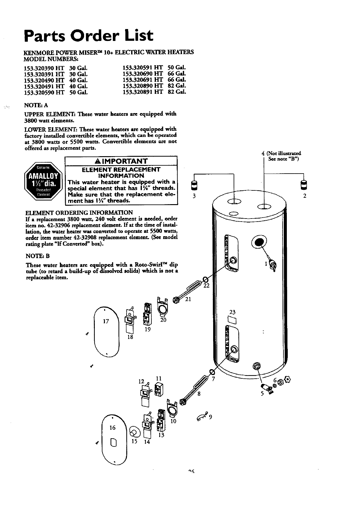
Parts Order List
KENMORE POWER MISER TM 10+ ELECTRIC WATER HEATERS
MODEL NUMBERS:
153.320390 HT 30 Gal.
153.320391 FIT 30 Gal.
153.320490 HT 40 Gal.
153.320491 HT 40 Gal.
153.320590 HT 50 Gal.
153.320591 HT 50 Gal.
153.320690 HT 66 Gal.
153.320691 HT 66 Gal.
153.320890 HT 82 Gal.
153.320891 HT 82 Gal.
NOTE: A
UPPER ELEMENT: These water heaters are equipped with
3800 watt dements.
LOWER ELEMENT: These water heaters are equipped with
factory installed convertible elements, which can be operated
at 3800 watts or 5500 watts. Convertible elements are not
offered as replacement parts.
AIMPORTANT
ELEMENT REPLACEMENT
INFORMATION
This water heater is equipped with a
special element that has I%" threads.
Make sure that the replacement ele-
ment has I%" threads.
4(Not illustrated
See note "B')
ELEMENT ORDERING INFORMATION
If a replacement 3800 watt, 240 volt element is needed, order
item no. 42-32906 replacement dement. If at the time of instal-
lation, the water heater was converted to operate at 5500 watts,
order item number 42-32908 replacement dement. (See model
rating plate "If Converted" box).
NOTE: B
These water heate_ are equipped with a Rote-Swirl TM dip
tube (to retard a braid-up of dissolved solids) which is not a
replaceable item.
11
23
%
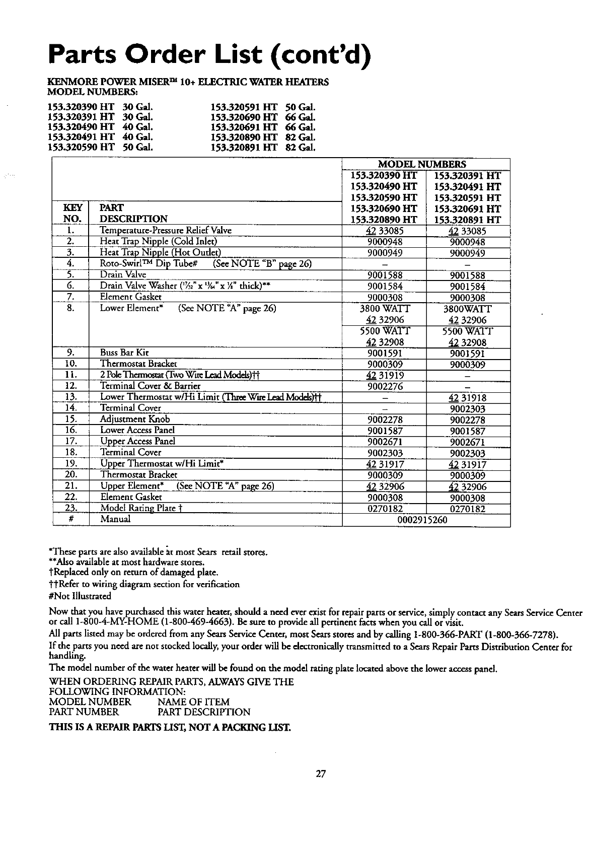
Parts Order List (cont'd)
KENMORE POWER MISER TM 10+ ELECTRIC WATER HEATERS
MODEL NUMBERS:
153.320390 HT 30 Gal.
153.320391 HT 30 Gal.
153.320490 HT 40 Gal.
153.320491 HT 40 Gal.
153.320590 HT 50 Gal.
153.320591 HT 50 Gal.
153.320690 HT 66 Gal.
153.320691 HT 66 Gal.
153.320890 liT 82 Gal.
153.320891 lit 82 Gal.
KEY PART
NO. DESCRIPTION
1. Temperature-Pressure Relief Valve
2. Heat Trap Nipple (Cold Inlet)
3. Heat Trap Nipple (Hot Oudet)
4. Roto-Swirl TM Dip Tube# (See NOTE "B" pa_e 26)
5. Drain Valve
6. Drain Valve Washer ('_2" x W64"x X" thick)**
7. Element Gasket
8. Lower Element* (See NOTE "A" page 26)
9.
10.
11.
12.
13.
14.
15.
16.
17.
18.
19.
20.
21.
22.
23.
#
Buss Bar Kit
Thermostat Bracket
2 Po!eThermostat(TwoWtre LeadModds)'M"
Terminal Cover & Barrier
Lower Thermostat w/Hi Limit (ThreeWke LeadModdsyti"
Terminal Cover
Adjustment Knob
LowerAccess Panel
Upper Access Panel
Terminal Cover
Upper Thermostat w/Hi Limit*
Thermostat Bracket
Upper Element* (See NOTE "A"page 26)
Element Gasket
Model Rating Plate 1
Manual
MODEL NUMBERS
153.320390HT
153.320490HT
153.320590HT
153.320690HT
153.320890HT
4233O85
9000948
9000949
9001588
9001584
9000308
3800WATT
4232906
5500WATT
4232908
9001591
9000309
4231919
9002276
9002278
9001587
9002671
9002303
4231917
9000309
4232906
9000308
0270182
153.320391 HT
153.320491 HT
153.320591 HT
153.320691 HT
153.320891HT
4233085
9000948
9000949
9001588
9001584
9000308
3800WATT
4232906
5500WATT
4232908
9001591
9000309
4231918
9002303
9002278
9001587
9002671
9002303
4231917
9000309
4232906
9000308
0270182
0002915260
*These parts arealso available _.tmost Sears retail stores.
**Alsoavailableat most hardware stores.
tReplaced only on return of damaged plate.
ttRefer to wiring diagram section for verification
#Not Illustrated
Now that you have purchased this water heater, should aneed ever exist for repair parts or service, simply contact any Sears Service Center
or call 1-800-4-MY-HOME (1-800-469-4663). Be sure to provide all pertinent facts when you call or visit.
All parts listed may be ordered from any Sears Service Center, most Sears stores and by calling 1-800-366-PART (1-800-366-7278).
If the parts you need are not stocked locally,your orderwill be dectronically transmitted to aSears Repair Parts Distribution Center for
handling.
The model number of the water heater will be found on the model rating plate located above the lower acc._s panel.
WHEN ORDERING REPAIRPARTS, ALWAYSGIVE THE
FOLLOWING INFORMATION:
MODEL NUMBER NAME OF ITEM
PART NUMBER PART DESCRIPTION
THIS IS A REPAIR PARTS LIST, NOT A PACKING LIST.
27
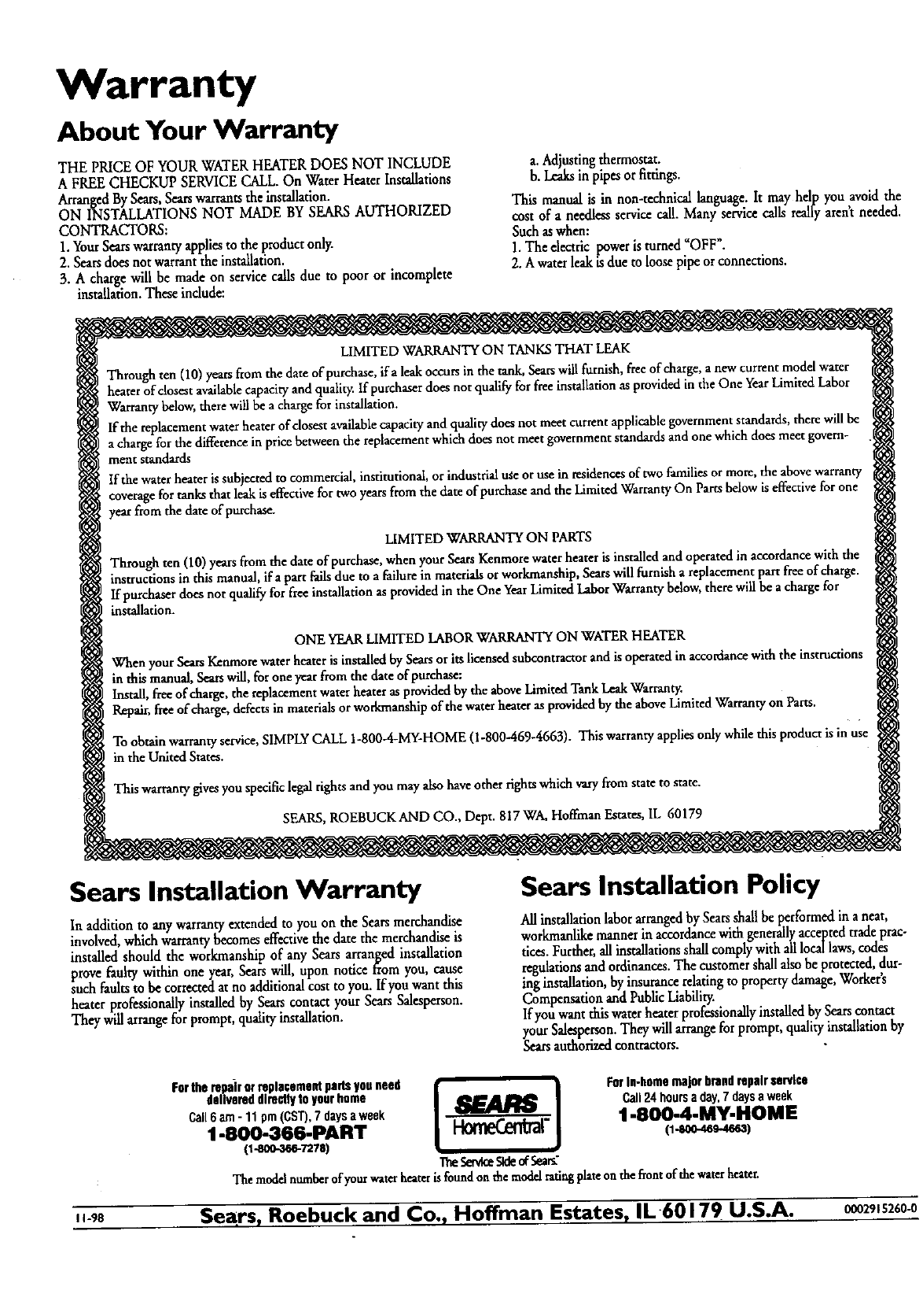
Warranty
About Your Warranty
THE PRICE OF YOUR WATERHEATER DOES NOT INCLUDE
A FREECHECKUP SERVICECALL.On Water Heater Installations
ArrangedBy Sears,Searswarrantsthe installation.
ON INSTALLATIONS NOT MADE BY SEARSAUTHORIZED
CONTRACTORS:
1.YourSearswarrantyappliesto the product only.
2. Seatsdoes not warrant the installation.
3. A charge will be made on service calls due to poor or incomplete
installation.These indude:
a_Adjustingthermostat.
b. Leaksin pipesor fittings.
This manual is in non-technical language. It may help you avoid the
cost of a needlessservicecall. Many service calls really arentneeded.
Suchaswhen:
1.The electric poweris turned =OFF".
2.A waterleak isdue to loosepipe or connections.
LIMITED WARRANTY ON TANKS THAT LEAK
Through ten (10) yearsfromthe date of purchase,ifa leakoccursin the tank, Searswillfurnish, freeof charge,anewcurrent model water
heaterof closestavalhblecapacityand quality:If purchaserdoesnot qualifyfor freeinstallationas providedinthe One YearLimited Labor
Warrantybelow,therewillbe a chargefor installation.
If the replacementwaterheaterof dosest availablecapacityand qualitydoes not meet currentapplicablegovernmentstandards,therewillbe
achargefor the differencein pricebetweenthe replacementwhichdoesnot meet governmentstandardsand onewhich doesmeet govern-
ment standa_
If thewaterheater issubjectedto commercial,institutional, or industrialu_eor usein residencesof two familiesor more, theabovewarrant
coveragefor tanks that leakiseffectivefor twoyearsfrom the date of purchaseand the LimitedWarrantyOn Partsbelowiseffectivefor one
year from the date of purchase.
LIMITED WARRANTYON PARTS
Through ten (10)yearsfrom the date of purchase,when your SearsKenmorewater heateris installedandoperatedin accordancewith the
instructionsin thismanual, lEaparr .railsdue to a failurein materialsor workma_hip, Searswillfurnish a replacementpart freeof charge.
If purchaserdoesnot qualifyfor freeinstallationas providedin the One YearLimitedLaborWarrantybelow,therewillbe a chargefor
installation.
ONE YEAR LIMITED LABOR WARRANTY ON WATER HEATER
When your SearsKenmorewaterheateris installedby Searsor itslicensedsubcontractorandisoperatedin accordancewith the instructions
in thismanual,&mrswil/,for oneyear from the dateof purchase:
Install,freeof charge,the replacementwater heateras providedbythe aboveLimkedTank LeakWarranty.
Repair,freeof charge,defectsin materialsor workmanshipof the waterheaterasprovidedbythe aboveLimitedWarrantyon Parts.
To obtain warrantyservice,SIMPLYCALL 1-800-4-MY-HOME(1-800-469-4663). This warrantyappliesonlywhilethis product isin use
in the United States.
Thiswarrantygivesyou specificlegalrights andyou mayalso haveotherfightswhichvaryfrom state to state.
SEARS,ROEBUCKAND CO., Dept. 817 WA,Hoffman Estates,IL 60179
Sears Installation Warranty
In additionto anywarranty extendedto you on the Sears merchandise
involved,which warrantybecomeseffectivethe date the merchandiseis
installed should the workmanship of any Seats arranl_ed installation
prove faulty within one year,Searswill, upon notice trom you, cause
such faultsto be corrected atno additionalcost to you. If you want this
heater professionallyinstalled by Seatscontact your SearsSalesperson.
They willarrangefor prompt, qualityinstallation.
Sears Installation Policy
All installationlaborarrangedbySeatsshallbe performed in aneat,
workmanlikemannerin accordancewith generallyacceptedtrade prac-
tices.Further,allinstallationsshallcomplywith alllocallaws,codes
regulationsandordinances.The customershallatsobe protected, dur-
ing installation,by insurancerelatingto propertydamage,Worker's
Compensationand PublicLiability.
If you want this water heaterprofessionallyinstalled bySearscontact
your Salesperson.They willarrangefor prompt, qualityinstallationby
Searsauthorizedcontractors.
Fortherepairorreplacementparisyouneed IForIn-homemajorbrandrepairservice
delivereddirectlytoyourhome I
@_JI!142 Call24hours
8day,
7daysaweek
Call6am-11pm(CST),7daysaweek _,s_rad'q'rnm. 1BBsOOm4mMyN HOM m
1-80Q-366-PART i-iomeLen_l 0-soo-q_-4s_)
0-eoo-3_727a) •
Themedalnumberofyourwaterheaterisfoundon themedalratingplateonthefloorofthewaterheater.
.-ge Se .rs, Roebuck and Co., Hoffman Estates, IL60179 U.S.A. 0002915260-0
