Kenmore Refrigerator 795 71022 010 Users Manual MFL63273703 A_100422
Kenmore Refrigerator 795-71022.010 145975-2
795-71022.010 to the manual 5acc5eab-015a-41c2-976c-99b3efd4689e
2015-01-24
: Kenmore Kenmore-Refrigerator-795-71022-010-Users-Manual-327668 kenmore-refrigerator-795-71022-010-users-manual-327668 kenmore pdf
Open the PDF directly: View PDF ![]() .
.
Page Count: 82
CAUTION
BEFORE SERVICING THE UNIT,
READ THE SAFETY PRECAUTIONS IN THIS MANUAL.
Model #s:
795.71022.010
795.71023.010
795.71024.010
795.71026.010
795.71029.010
REFRIGERATOR
SERVICE MANUAL
P/No. MFL63273703

- 2 -
CONTENTS
SAFETY PRECAUTIONS
Please read the following instructions before servicing your
refrigerator.
1. Unplug the power before handling any elctrical
componets.
2. Check the rated current, voltage, and capacity.
3. Take caution not to get water near any electrical
components.
4. Use exact replacement parts.
5. Remove any objects from the top prior to tilting the
product.
SAFETY PRECAUTIONS ....................................................................................................................................................... 2
1. SPECIFICATIONS ........................................................................................................................................................... 3-4
2. PARTS IDENTIFICATION .................................................................................................................................................. 5
3. DISASSEMBLY ............................................................................................................................................................. 6-17
REMOVING AND REPLACING REFRIGERATOR DOORS ............................................................................................... 6
DOOR .............................................................................................................................................................................. 7-8
DOOR ALIGNMENT ........................................................................................................................................................... 8
FAN AND FAN MOTOR(Evaporator) .................................................................................................................................. 8
DEFROST CONTROL ASSEMBLY .................................................................................................................................... 9
LAMP .................................................................................................................................................................................. 9
MULTI DUCT .................................................................................................................................................................... 10
MAIN PWB ........................................................................................................................................................................ 10
DISPENSER .......................................................................................................................................................................10
DISPLAY PWB REPLACEMENT....................................................................................................................................... 11
FUNNEL REPLACEMENT..................................................................................................................................................11
SUB PWB FOR WORKING DISPENSER...........................................................................................................................11
DUCT DOOR REPLACEMENT .........................................................................................................................................11
ICE CORNER DOOR REPLACEMENT..............................................................................................................................12
ICEMAKER ASSEMBLY .....................................................................................................................................................12
AUGER MOTOR COVER ...................................................................................................................................................12
HOW TO REMOVE A DOOR ICE BIN................................................................................................................................13
HOW TO INSERT A DOOR ICE BIN ..................................................................................................................................13
HOW TO REMOVE AND REINSTALL THE PULLOUT DRAWER................................................................................14-15
WATER VALVE DISASSEMBLY METHOD........................................................................................................................16
FAN AND FAN MOTOR DISASSEMBLY METHOD...........................................................................................................16
PULL OUT DRAWER..........................................................................................................................................................17
4. ADJUSTMENT ............................................................................................................................................................ 18-20
COMPRESSOR ................................................................................................................................................................ 18
INTRODUCTION OF E-LINEAR COMPRESSOR........................................................................................................ 18-20
5. CIRCUIT DIAGRAM ......................................................................................................................................................... 21
6. TROUBLESHOOTING ...................................................................................................................................................... 22
7. PCB PICTURE.............................................................................................................................................................. 23-24
8. TROUBLESHOOTING WITH ERROR DISPLAY......................................................................................................... 25-33
9. TROUBLESHOOTING WITHOUT ERROR DISPLAY...................................................................................................34-42
10. REFERENCE ...............................................................................................................................................................43-48
11. COMPONENT TESTING INFORMATION ..................................................................................................................49-57
12. TROUBLESHOOTING ................................................................................................................................................58-64
13. OPERATION PRINCIPLE AND REPAIR METHOD OF ICEMAKER..........................................................................65-67
14. DESCRIPTION OF FUNCTION & CIRCUIT OF MICOM.............................................................................................68-71
- 3 -
1. SPECIFICATIONS
Defrost Thermostat ....................................... 6615JB2005H
Defrost Heater ............................................... 5300JK1005D
Evaporator Fan Motor ................................... 4681JB1027C
(4681JK1004E)
Capacitor (Running) ..................................... EAE58905701
Compressor (Hi-Side) ................................... TCA34649901
Evaporator (Lo-Side) ..................................... 5421JJ1003B
Condenser ................................................... ACG72915205
Dryer ............................................................. 5851JA2007E
Condenser Fan Motor ................................... 4681JB1029D
Temperature Control ............................ ACQ36820516(SW)
ACQ36820517(STS)
ACQ36820518(TI)
ACQ36820519(WB)
ACQ36820520(BI)
Main Control ................................................. EBR67348003
Ice Fan Motor ................................................ 4681JB1027E
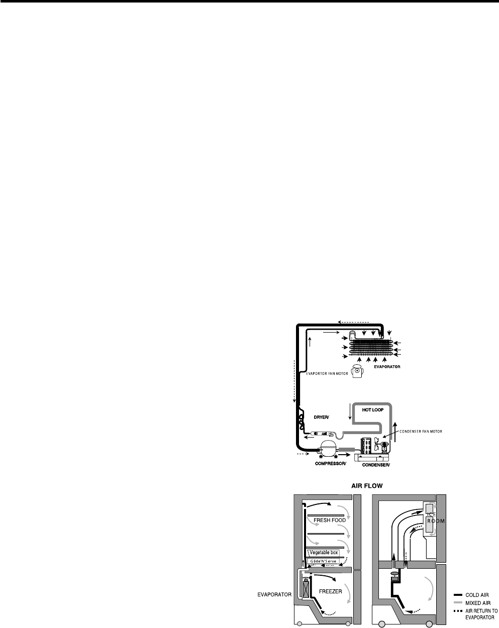
1-8 AIR FLOW / CIRCULATION D’AIR
1-7 REPLACEMENT PARTS
25 cuft
795.71022.010
795.71023.010
795.71024.010
795.71026.010
795.71029.010
1-1 DISCONNECT POWER CORD BEFORE
SERVICING
IMPORTANT - RECONNECT ALL
GROUNDING DEVICES
All parts of this appliance capable of conducting electrical
current are grounded. If grounding wires, screws, straps,
clips, nuts or washers used to complete a path to ground
are removed for service, they must be returned to their
original position and properly fastened.
1-2 IMPORTANT NOTICE
This information is intended for use by individuals
possessing adequate backgrounds of electrical, electronic
and mechanical experience. Any attempt to repair a major
appliance may result in personal injury and property
damage. The manufacturer or seller cannot be responsible
for the interpretation of this information, nor can it assume
any liability in connection with its use.
1-3 ELECTRICAL SPECIFICATIONS
Temperature Control (Freezer Compartment) .. -6°F to +8°F
Defrost Control .....Total Comp Running Time: 7 hrs~50 hrs
Defrost Thermostat ...................................................... 46°F
Electrical Rating : 115VAC, 60Hz ................................ 5.2 A
Maximum Current Leakage ...................................... 0.5 mA
Maximum Ground Path Resistance ................... 0.14 Ohms
Energy Consumption ....................... 25 cu.ft. 547 (E/STAR)
1-5 REFRIGERATION SYSTEM
Minimum Compressor Capacity Vacuum ................ 21 MIN.
Minimum Equalized Pressure
@ 70°F ............................................................ 49 PSIG
@ 90°F ............................................................ 56 PSIG
Refrigerant R134a ................................................... 4.94 oz.
Compressor ....................................................... 956 BTU/hr
1-6 INSTALLATION
Clearance must be provided at top, sides and rear of the
refrigerator for air circulation.
AT REAR ....................................................................... 2 in
1-4 NO LOAD PERFORMANCE
CONTROL POSITION : MID/MID
And Ambient of : ................ 70°F ................................. 90°F
Fresh Food, °F .................. 33°F to 41°F ........ 33°F to 41°F
Frozen Food, °F ................ -4°F to +4°F ......... -4°F to +4°F
Percent Running Time ...... 35%-45% ................. 50°F-70°F
- 4 -
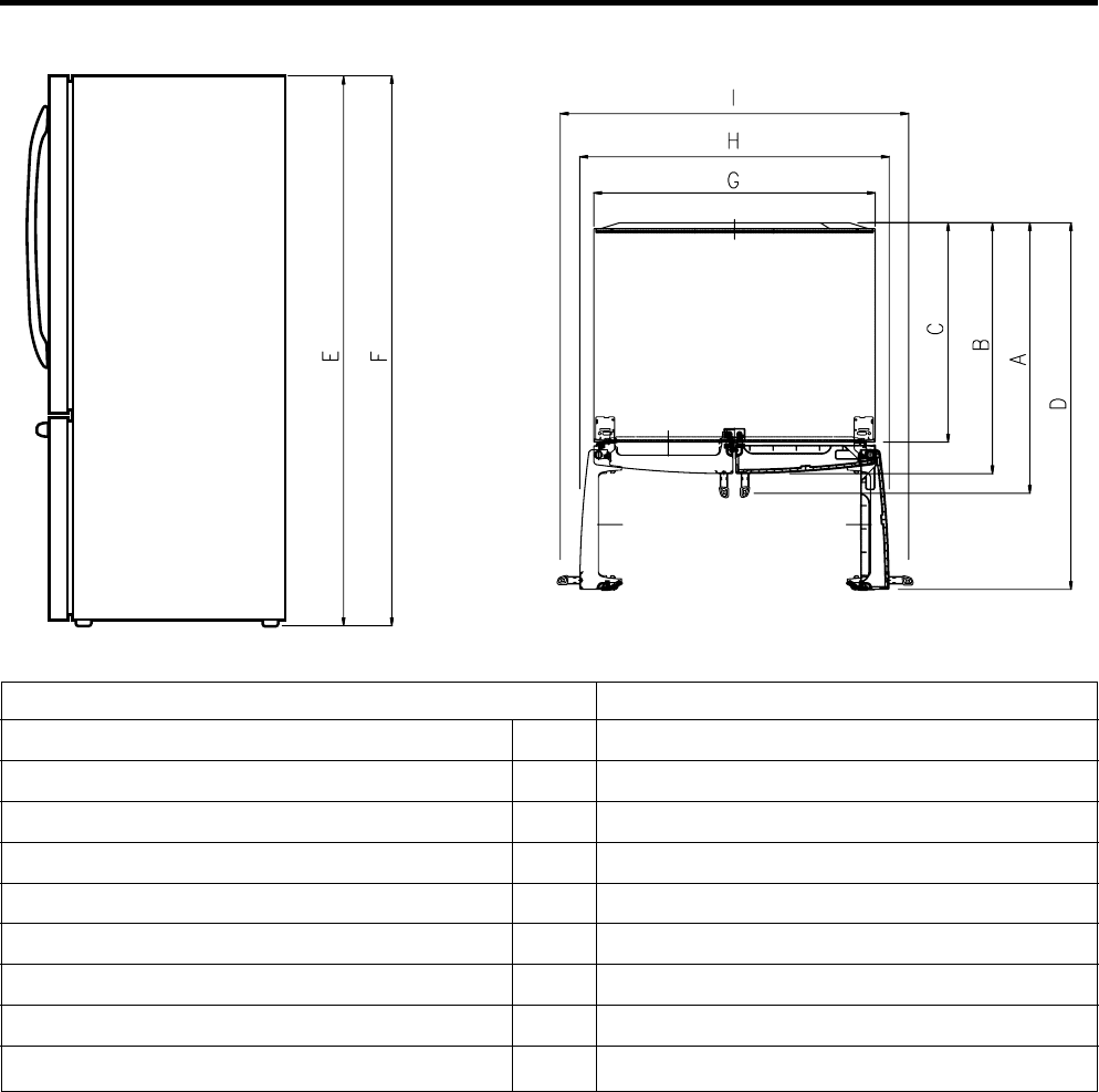
Depth w/ Handles
Depth w/ Handles
Depth w/ o Door
Depth (Total with Door Open)
Height to Top of Case
Height to Top of Door Hinge
Width
Width (door open 90 deg. w/o handle)
Width (door open 90 deg. w/ handle)
A
B
C
D
E
F
G
H
I
34 1/4 in
31 3/4 in
27 7/8 in
46 1/2 in
68 3/8 in
69 3/4 in
35 3/4 in
39 1/4 in
44 1/4 in
Description 795.710*
- 5 -
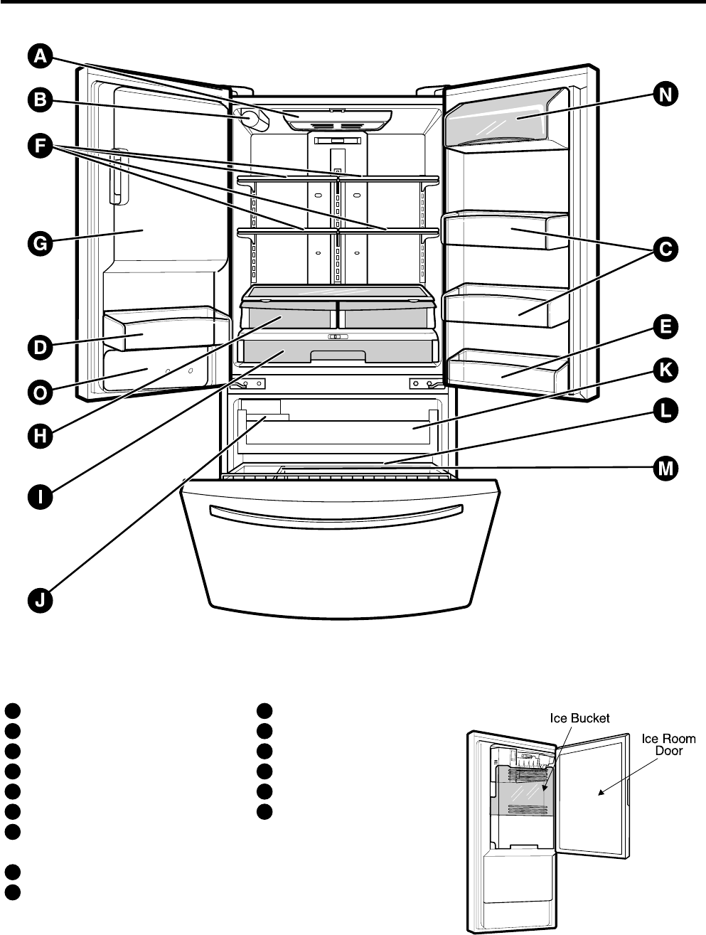
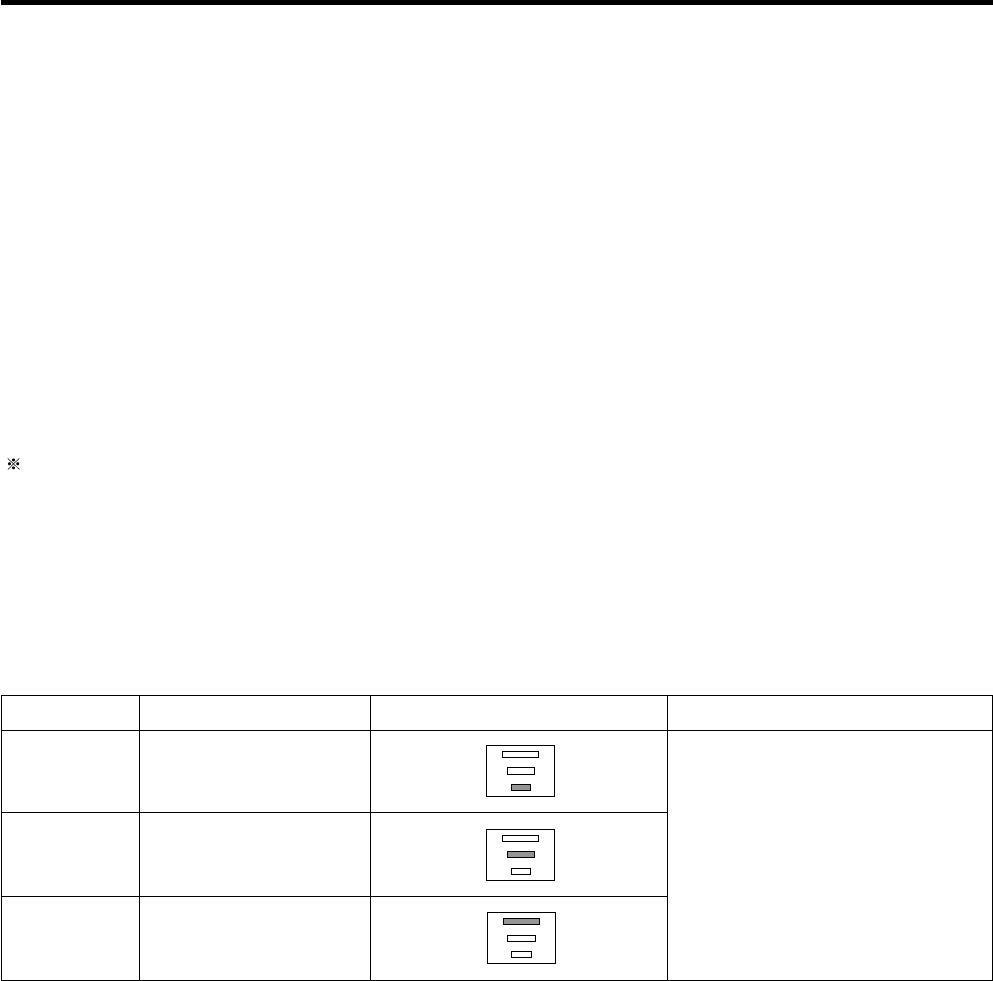
2. PARTS IDENTIFICATION
Refrigerator Light
Filter (Inside)
Modular Door Bins
Fixed door bin
Fixed door bin
Refrigerator Shelves
Ice Room
(Ice Maker and Ice Bucket)
Humidity Controlled Crisper
Glide’N’Serve
A
B
C
D
E
F
G
H
I
Extra Ice Bin
Pull out Drawer
Durabase
Divider
Dairy Bin
Water Tank Cover
J
K
L
M
N
O
Use this page to become more familiar with the parts and features. Page references are included for your convenience.
NOTE : This guide covers several different models. The refrigerator you have purchased may have some or all of the items
listed below. The locations of the features shown below may not match your model.
3. DISASSEMBLY
- 6 -
3-1 REMOVING AND REPLACING REFRIGERATOR DOORS
To remove the left refrigerator door:
On the back of the refrigerator, press back on the release
ring of the fitting (see 3 in figure below) and pull out the
water tube in the direction of the arrow.
To remove the right refrigerator door:
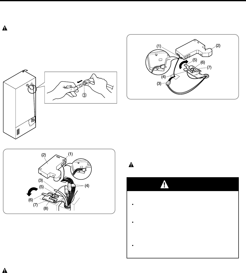
1. Open the door. Remove the top hinge cover screw (1).
2. Use a flat-head screwdriver to pry back the hooks (not
shown) on the front underside of the cover (2).
Lift up the cover.
3. Remove the cover. Pull out the tube (3).
4. Disconnect all the wire harnesses (4).
5. Remove the grounding screw (5).
6. Rotate hinge lever (6) counterclockwise.
Lift the top hinge (7) free of the hinge lever latch (8).
7. Remove the door by lifting it off the middle hinge pin,
located at the bottom of the door.
8. Place the door on a soft, smooth surface with the inside
up to prevent damage.
1. Open the door. Remove the top hinge cover screw (1).
Lift up cover (2).
2. Remove cover.
3. Disconnect wire harness (3).
4. Remove the grounding screw (4).
5. Rotate hinge lever (5) clockwise.
Lift top hinge (6) free of hinge lever latch (7).
6. Remove the door by lifting it off the middle hinge pin,
located at the bottom of the door.
7. Place the door on a soft, smooth surface with the inside
up to prevent damage.
Electrical Shock Hazard
Disconnect electrical supply to the refrigerator
before installing. Failure to do so could result in
death or serious injury.
Do not put hands or feet or other objects into
the air vents, base grille, or bottom of the
refrigerator. You may be injured or receive an
electrical shock.
Be careful when you work with the hinge, base
grille, and stopper. You may be injured.
CAUTION : Before you begin, unplug the refrigerator
and remove the food and bins from the doors.
CAUTION : When lifting the hinge free of the latch, be
careful that the door does not fall forward.
WARNING
CAUTION : When lifting the hinge free of the latch, be
careful that the door does not fall forward.
3-2 DOOR
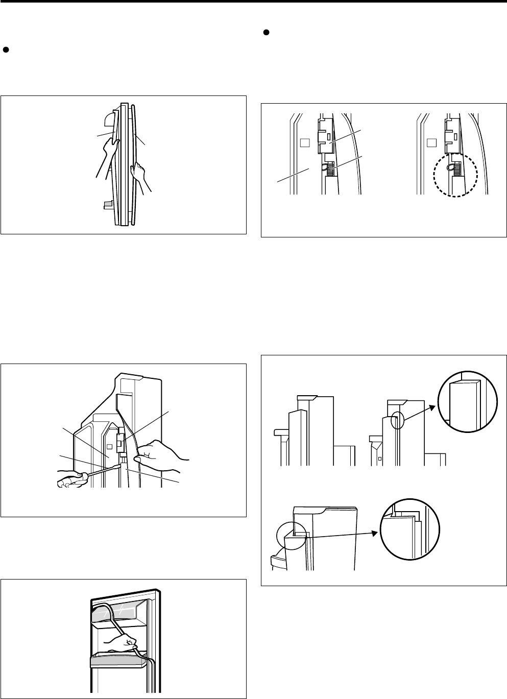
Door Gasket Removal
1. Remove door frame cover
Starting at top of cover and working down, snap cover
out and away from door.
Door Gasket Replacement
1. Insert gasket bracket clips
1) Insert gasket bracket edge beneath door frame edge.
2) Turn upper gasket bracket spring so that the spring
ends are in the door channel.
3) Push in clip until you hear it snap securely into place.
2. Insert gasket into channel
1) Snap gasket assembly into the door bracket.
<Inserting the Gasket Assembly into the Bracket Door>
4) Push in remaining clip until you hear it snap securely
into place.
Note : Make sure that no part of gasket bracket edge
protrudes from beneath door frame edge.
2. Remove gasket bracket clips
There are two clips on each door. Start bracket removal
near one of the middle clips.
1) Pull gasket back to expose gasket bracket clip and
door frame.
2) Insert a flat tip screwdriver into seam between gasket
bracket and door frame and pry back until clips snap
out.
3) Continue prying back along seam until all clips snap
out.
3. Remove gasket
Pull gasket free from gasket channel on the three
remaining sides of door.
Figure 1
Frame Cover
Handle
Figure 4
Figure 5
Door
Frame
Correct
Correct
Incorrect
Incorrect
Figure 2
Door
Frame
Gasket
Bracket Clip
Gasket
Bracket
Flat Tip
Screwdriver
Figure 3
- 7 -
Spring
Gasket
Bracket Clip
- 8 -
3. Replace door frame cover
Starting at top of cover and working down, snap cover
back into door.
2) Press gasket into channels on the three remaining
sides of door.
Figure 6
Figure 10
Figure 11
Figure 7
3-3 DOOR ALIGNMENT
If the space between your doors is uneven, follow the
instructions below to align the doors :
1. With one hand, lift up the door you want to raise at
middle hinge.
2. With other hand, use pliers to insert snap ring as shown.
3. Insert additional snap rings until the doors are aligned.
(Three snap rings are provided with unit.)
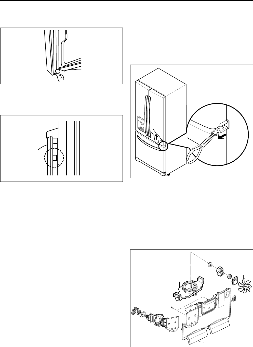
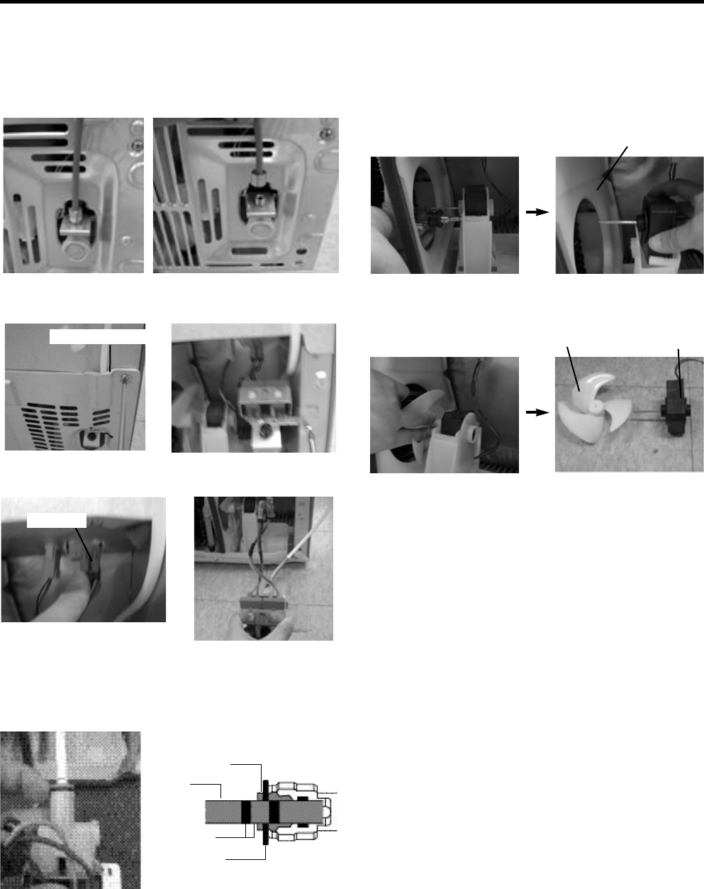
3-4 FAN AND FAN MOTOR(EVAPORATOR)
1. Remove the freezer shelf. (If your refrigerator has an
icemaker, remove the icemaker first)
2. Remove the plastic guide for slides on left side by
unscrewing phillips head screws.
3. Remove the grille by removing one screw and pulling the
grille forward.
4. Remove the Fan Motor assembly by loosening 2 screws
and disassembling the shroud.
5. Pull out the fan and separate the Fan Motor and Bracket.
BRACKET
MOTOR
GRILLE
FAN MOTOR
FAN
- 9 -
*Ice Fan Scroll Assembly Replacement
1) Remove the plastic guide for slides on left side by
unscrewing phillips head screws.
2) Pull the grille forward as shown in the second picture.
3) Disconnect wire harness of the grille.
4) Remove the scroll assembly by loosening all screws.
(3) (4)
(1) (2)
3-5 DEFROST CONTROL ASSEMBLY
Defrost Control assembly consists of Defrost Sensor and
FUSE-M.
The Defrost Sensor works to defrost automatically. It is
attached to the metal side of the Evaporator and senses its
temperature. At 46°F (8°C), it turns the Defrost Heater off.
Fuse-M is a safety device for preventing over-heating of the
Heater when defrosting.
1. Pull out the grille assembly. (Figure 10)
2. Separate the connector with the Defrost Control
assembly and replace the Defrost Control assembly after
cutting the Tie Wrap. (Figure 11)
Figure 10 Figure 11
GRILLE ASSEMBLY DEFROST-CONTROL
ASSEMBLY
Figure 12
Figure 13
Figure 14
Cover, Lamp LED, Assembly Case Lamp
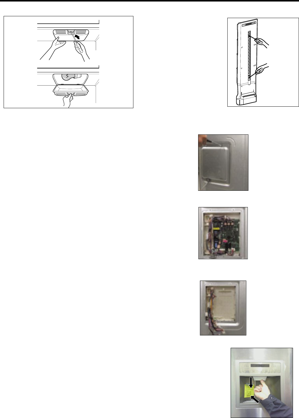
3-6 LAMP
Unplug Refrigerator, or disconnect power at the circuit
breaker.
If necessary, remove top shelf or shelves.
1) Release 2 screws.
2) Hold both ends with your both hands and pull it
downward to remove it.
3) Use a flat tool as shown below to remove the cover
lamp.
4) As shown below, use a flat tool to remove the cover
lamp.
3-6-1 Refrigerator Compartment Lamp
- 10 -
3-7 MULTI DUCT
1. Remove the upper and
lower Caps by using a
flat screwdriver, and
remove 2 screws.
(Figure 17)
2. Disconnect the lead wire
on the bottom position.
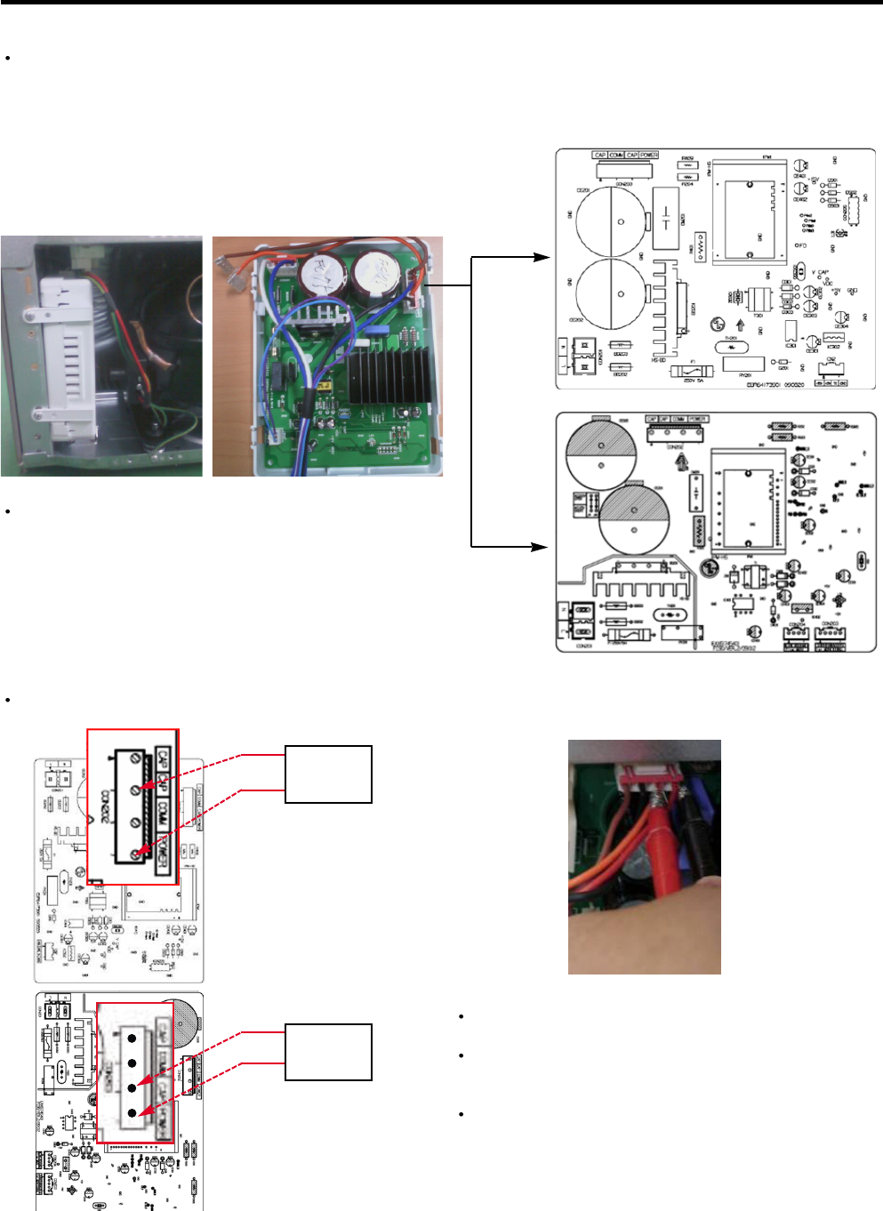
3-8 MAIN PWB
1) Loosen the 4 screws on the PWB cover.
Figure 17
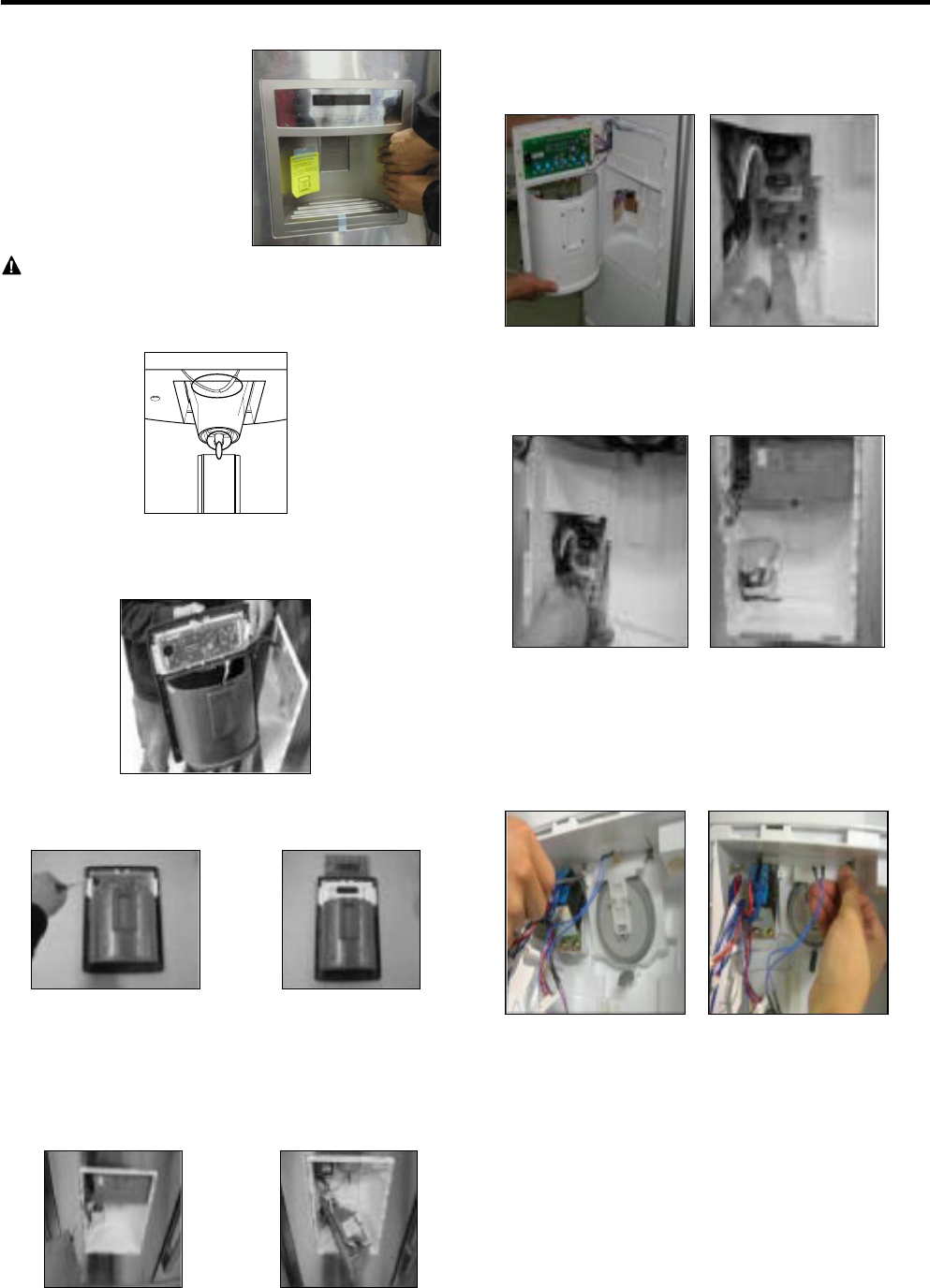
3-9 DISPENSER
1) Disconnect funnel and
button assembly by
pulling down and
forward.
2) Remove the PWB cover
3) Disconnect wire harness and replace the main PWB in
the reverse order of removal.
NOTE: Some models have LED interior lighting and service
should be performed by a qualified technician.
1. Unplug refrigerator power cord form outlet.
2. Using a flat instrument, gently pry the lamp cover loose
in the front as shown. Rotate downward to remove the
rear tabs.
3. Make sure the bulb is cool to the touch. Turn the bulb
counterclockwise to remove.
4. Replace with a new 60-watt appliance bulb.
5. Insert tabs on back of cover into slots in freezer ceiling.
Push cover up to snap front into place.
To change freezer light
- 11 -
3-12 SUB PWB FOR WORKING DISPENSER
1) Loosen the screw on the sub PWB.
3-13 DUCT DOOR REPLACEMENT
1) Pull up and out on the dispenser cover to remove.
2) Disconnect the wire harness.
3) Remove the funnel
4) Replace in reverse order.
2) Pull the sub PWB down.
3) Disconnect the wire harness and replace the sub PWB in
the reverse order of removal.
CAUTION : When replacing the dispenser cover in the
reverse order of removal, be careful that the lead wire
does not come out and the water tube is not pinched by
the dispenser cover, as shown in the picture below.
2) Hold the left and right side
of the “Cover Assembly,
dispenser” as shown in the
picture, and pull and
remove it. The cover
dispenser is attached with a
hook.
3-10 DISPLAY PWB REPLACEMENT
1) Pull up and out on the dispenser cover to remove.
3-11 FUNNEL REPLACEMENT
1) Pull up and out on the dispenser cover to remove.
2) Disconnect the wire harness.
3) Replace in reverse order.
2) Follow the steps in the pictures
- 12 -
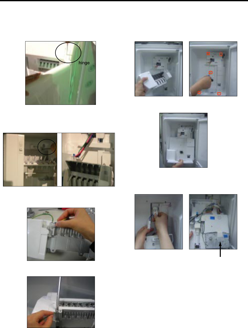
3-16 AUGER MOTOR COVER
1) After removing the icemaker remove the (5) stainless
screws holding the auger motor cover, shown in the
picutres below.
2) Grip the bottom of motor cover assembly and pull out it.
3) Disconnect wire harness of motor cover assembly.
There is a auger motor on the back, as shown in the
picture.
Auger Motor
3-14 ICE CORNER DOOR REPLACEMENT
1) Loosen the front screw as shown in the picture.
2) Lift up the hinge with one hand.
3) Pull out the Ice Corner Door with the other hand.
3-15 ICEMAKER ASSEMBLY
1) Loosen two screws as shown in the first picture.
2) Disconnect the wire harness & ground screw replace
theIcemaker assembly in the reverse order of removal.
3) It separates a ground connection screw.
- 13 -
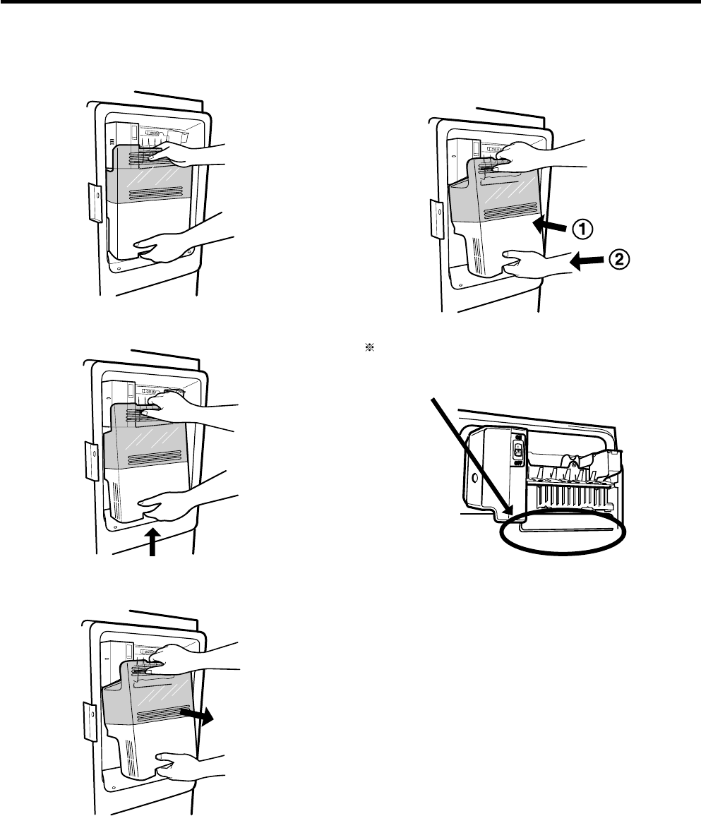
3-17 HOW TO REMOVE A DOOR ICE BIN
1) Grip the handles, as shown in the picture.
3-18 HOW TO INSERT A DOOR ICE BIN
1) Insert the Ice Bin, slightly tilting it to avoid touching the
Icemaker. (especially, ice maker lever)
Insert the ice bucket carefully avoid contacing the
automatic shut off arm.
2) Lift the lower part slightly.
3) Take the Ice Bin out slowly.
- 14 -
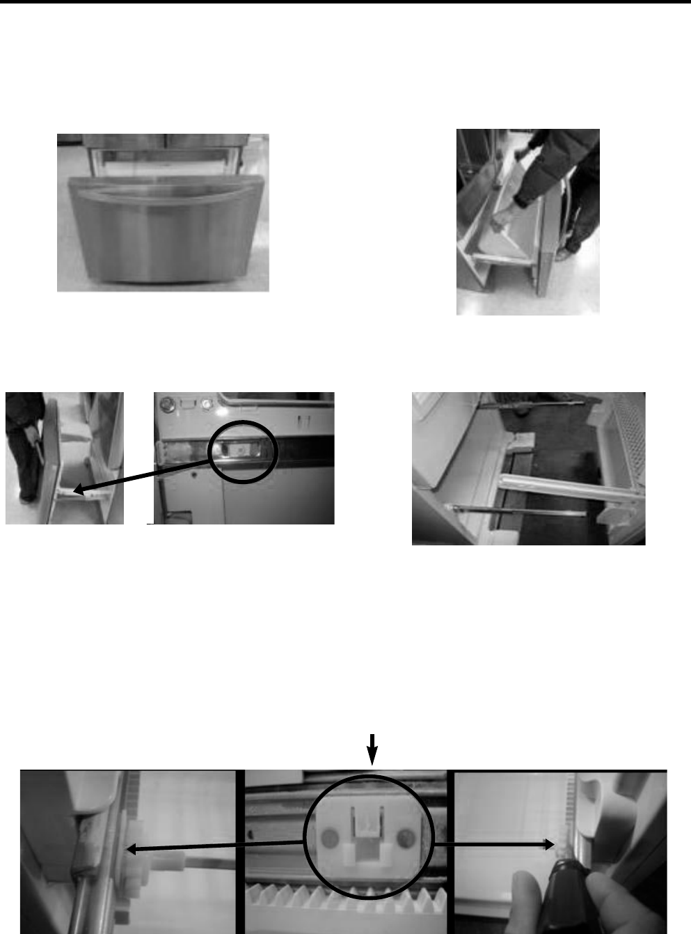
3-19 HOW TO REMOVE AND REINSTALL THE PULLOUT DRAWER
3-19-1 Follow Steps to Remove
Step 1) Open the freezer door. Step 2) Remove the lower basket.
Step 3) Remove the two screws from the guide rails (one
from each side).
Step 5) First : Remove the gear from the left side first by releasing the tab behind the gear, place a screwdriver between the
gear and the tab and pull up on the gear.
Second : Remove the center rail.
Third : Remove the gear from the right side by following the same steps for the left side.
NOTE : THIS TAB MUST BE PUSHED IN TO RELEASE THE GEAR.
Step 4) Lift the freezer door up to unhook it from the rail
support and remove.
Pull both rails to full extension.
- 15 -
3-19-2 Follow Steps to Reinstall
Step 1) Reinstall the right side gear into the clip.
Step 2) Insert the rail into the right side gear. Gears do not
need to be perpendicular to each other.
Step 4) The rail system will align itself by pushing the rails
all the way into the freezer section.
Pull the rails back out to full extension.
Step 5) Reinstall the freezer door by inserting the rail tabs
into the guide rail.
Step 6) Reinstall the two screws into the guide rails
(one from each side).
Step 7) Reinstall the lower basket, and close the freezer
door.
Step 3) Insert the rail into the left side gear, and insert the
gear into the clip.
- 16 -
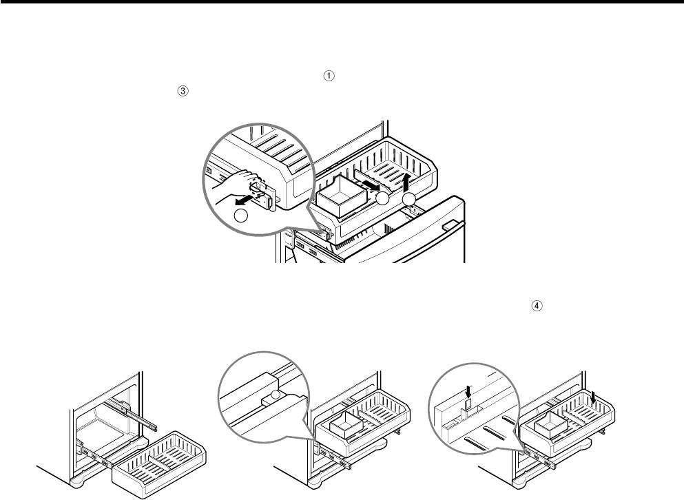
3-20 WATER VALVE DISASSEMBLY METHOD
1) Turn off the water. Then separate the water line from the
valve.
3-21 FAN AND FAN MOTOR DISASSEMBLY
METHOD
1) Using a short screwdriver, loosen one SCREW in DRAIN
PIPE ASSEMBLY and one connected to the MOTOR
COVER.
2) Separate the Mechanical Cover and Valve Screw.
3) Separate the housing and pull out the valve.
4) Lay a dry towel on the floor and get ready to spill water
from the water filter. Pull out the Cilp. Then press te
collet to separate the tube from the connector and pour
out the water until emptied.
Mechanical Cover
Housing
MOTOR COVER
2) Pull and separate the FAN ASSEMBLY and MOTOR
turning counterclockwise based on the MOTOR SHAFT.
The assembly is in the reverse order of the disassembly
and take special care for the following details.
1. Be careful not to bend the tube during assembly.
2. Press the WATER DISPENSER button until water pours
out and check for leakage in the CONNECTOR TUBE (It
differs by the water pressure but usually takes about 2
minutes until water pours out.)
FAN ASSEMBLY MOTOR
Collet
Tube
Insert Line
Clip
- 17 -
3-22 PULL OUT DRAWER
Separate the drawer, push the front left and right hooks in direction to pull up and remove.
Then gently lift and pull it out in direction.
2
3
1
To install, After pulling out both rails as much as possible, and insert an end of rib to the bracket at left and right then
gently push down both left and right side while checking the hook on the front part.
4
Hook
4. ADJUSTMENT
- 18 -
4-2 Introduction of E-Linear Compressor
E-Linear compressor is run by mechanical part design
through automatically varying the cooling power. The
main parts consist of compressor and Sub PCB which
controls the compressor. PCB authorizes constant
voltage and constant frequency to the compressor and
protects it.
Drive half stroke after turning on initial power for 30
seconds. Then, slowly increase stroke and reach target
input. Once reaching the target input, input naturally
changes according to refrigerator load without any special
control.
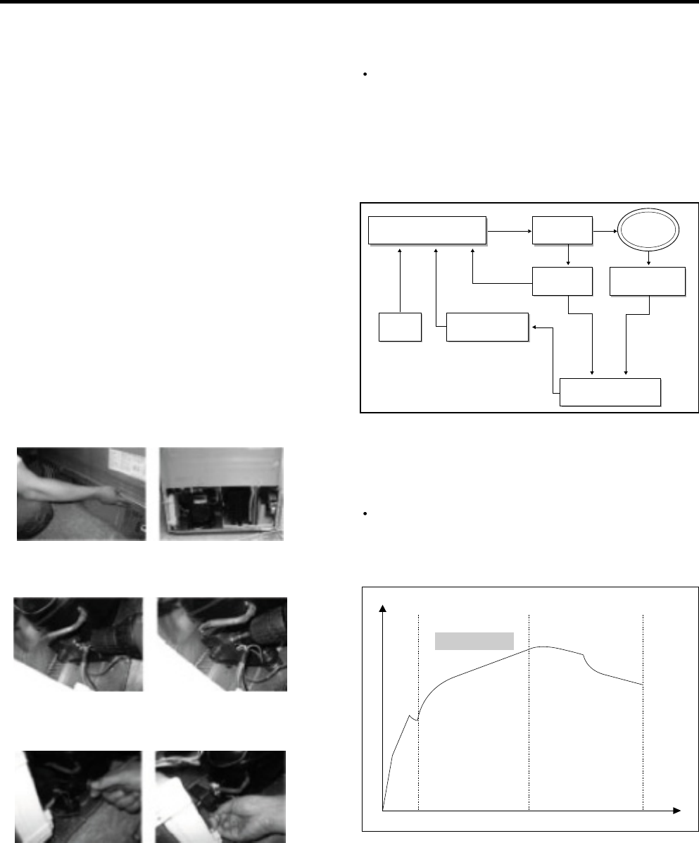
Interval 1) Half stroke interval - after initial running, stay at
the initial value for 30 seconds
Interval 2) Running interval - Increase at every 0.8 till it
reaches the target input; it takes about
3 Minutes and 45 seconds.
Interval 3) CVCF interval - Run by target voltage and main
operating frequency and the input naturally
changes according to refrigerator load
❸
❶❷
4-1-1 Role
4-1 COMPRESSOR
The compressor intakes low temperature and low pressure
gas from the evaporator of the refrigerator and compresses
this gas to high-temperature and high-pressure gas. It then
delivers the gas to the condenser.
4-1-2 Note for Usage
(1) Be careful not to allow over-voltage and over-current.
(2) Do not drop or handle carelessly.
(3) Keep away from any liquid.
If liquid such as oil or water enters the Cover PTC
Compressor may fail due to breakdown of their
insulating capabilities.
(4) Always use the Parts designed for the compressor and
make sure it is properly attached to the compressor.
Parts may appear physically identical but could have
different electrical ratings. Replace parts by part number
and model number. Use only approved substitute parts.
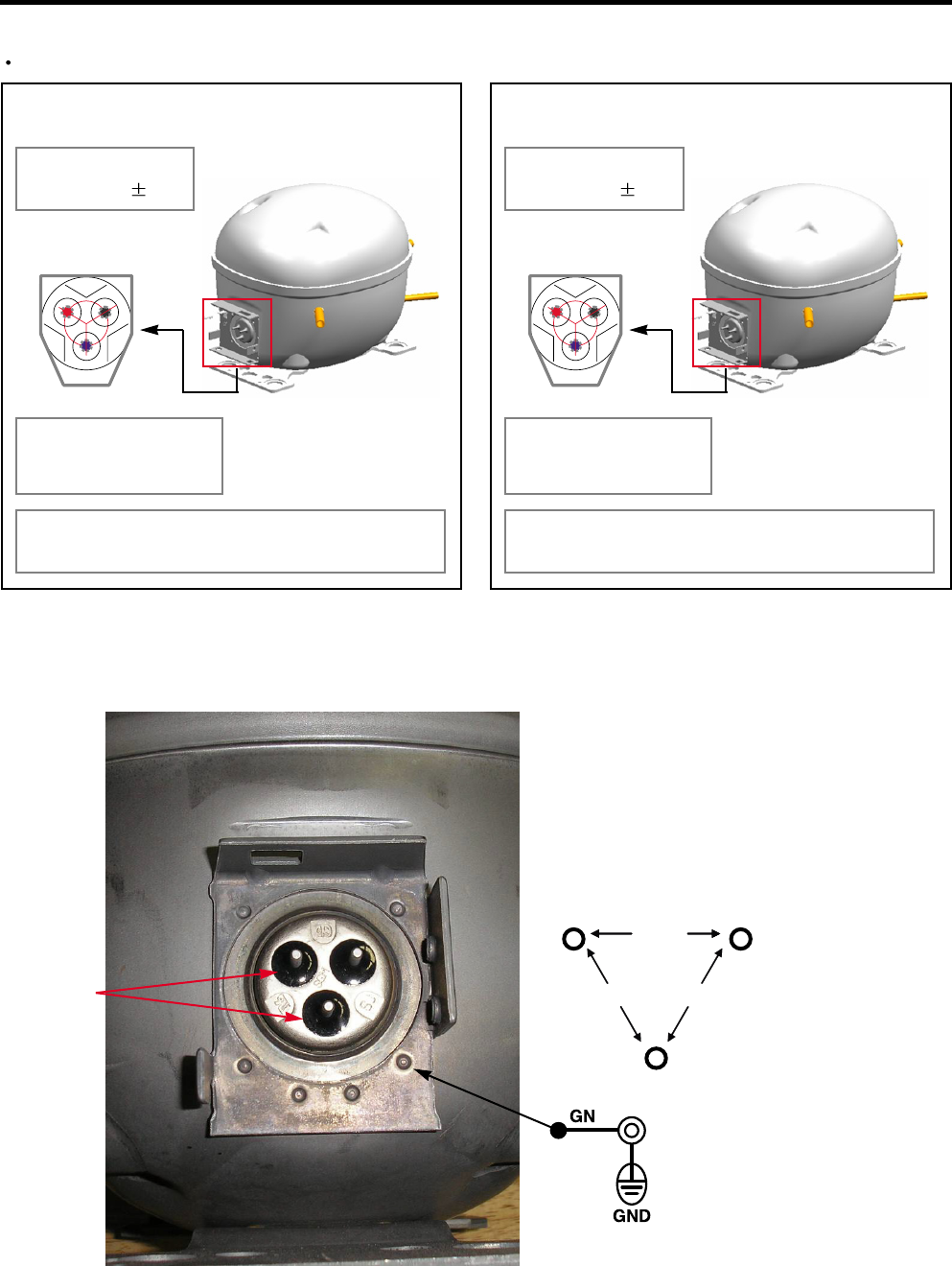
4-1-3 REMOVE THE COVER PTC
(1) Remove the Cover Back M/C
(2) Loosen two screws on comp base
(3) Use a L-shaped flap tooll to pry off the cover
(4) Assembly in reverse order of disassembly
4-2-1 Control of Compressor Block Diagram
4-2-2 Compressor operating pattern
Compressor Controller Inverter
PWM
Signal
Frequ
-ency
Linear
Comp
DC link
Voltage
Main
Micom
Calculate counter
electromotive force
Counter elec-
tromotive force
Vcap Voltage
Control Block Diagram of Compressor
Comp. input
- 19 -
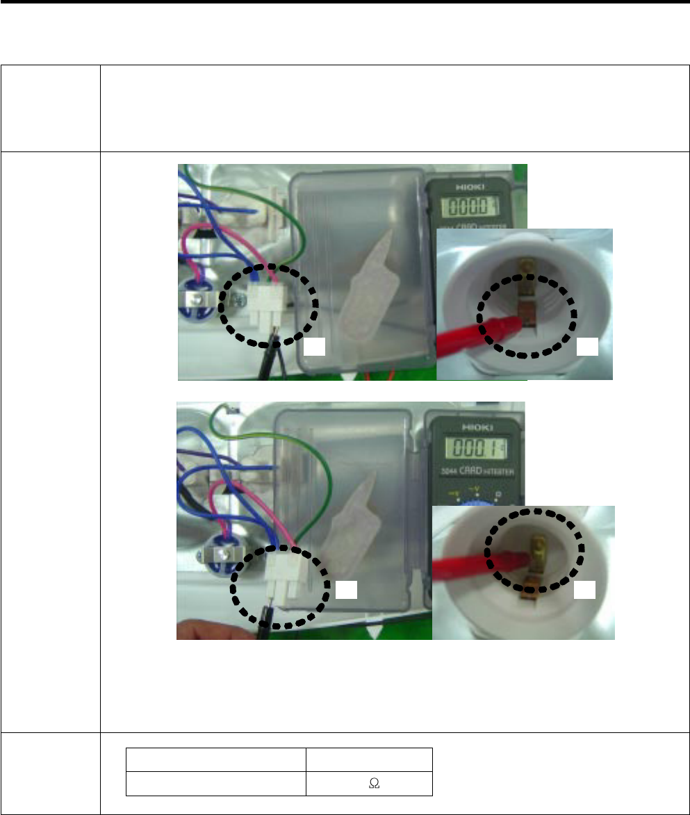
4-2-4 Compressor problems diagnosis
When there is a problem or failure with the `operation,
you are kindly recommended to check it as follows ;
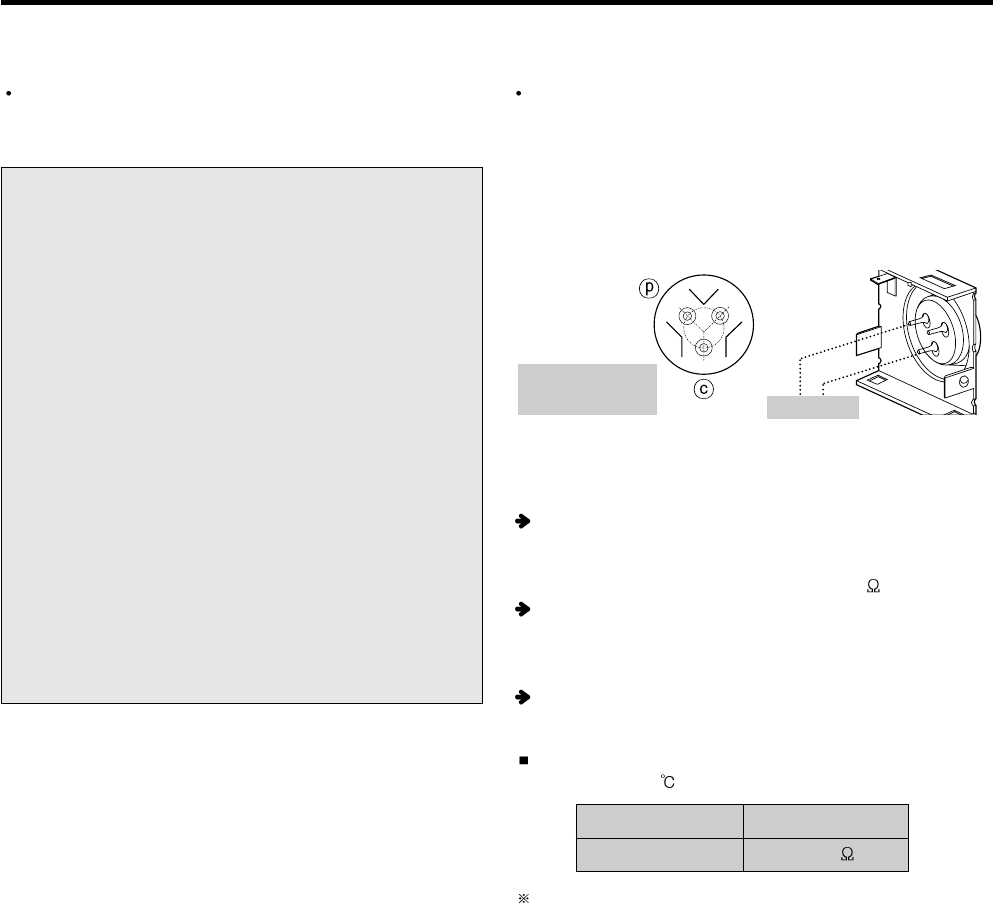
Measure the resistance between poles of the hermetic
terminal (as shown picture) with a multi-tester.
(measurement several minutes after power off)
Normal resistance range (measured at ambient
temperature 23 )
Case 1-1
If the measured values lie in the normal resistance range as
in the table below,
Compressor is normal.
Case 1-2
If the measured values are above several M or a infinity,
Wire is disconnected in the shell.
Case 1-3
If the measured values are excessively of small number,
There is short somewhere in the shell.
1) Check to normality by measurement of resistance
According to ambient temperature or operation situation,
the values could show a little deviation.
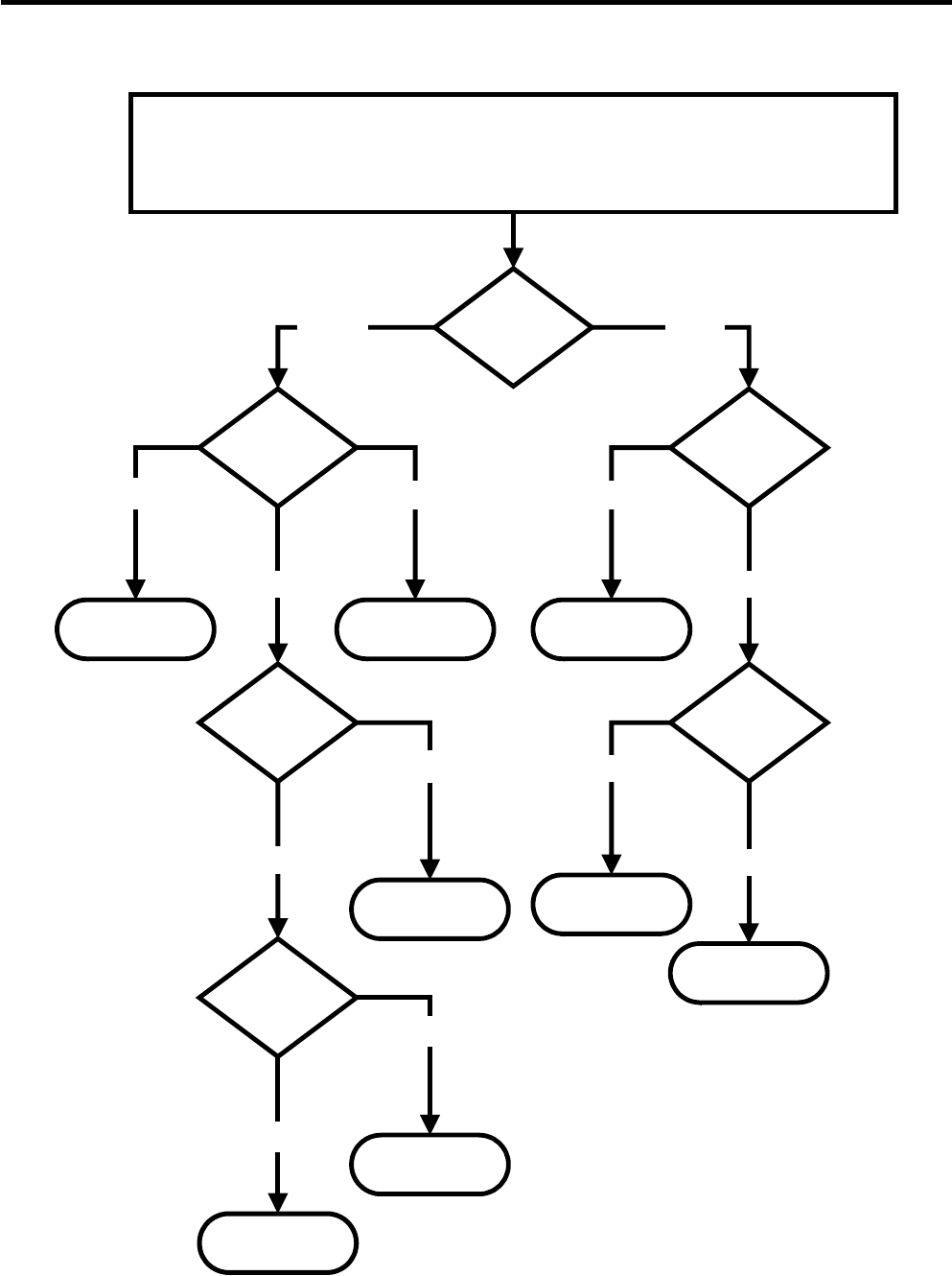
4-2-3 Compressor protection logic
Since linear Comp conducts linear reciprocating motion,
we have protection logic for compressor, motor and PCB
as the below.
-Stroke Trip
During the operation, if stroke is above the target value,
decrease the target volt by 3V.
-Current Trip
Current trip is set in order to protect compressor
mechanical part and drive from the overcurrent that might
arise during the operation.
Check the current for every 416.7us and if the Trip
exceeds 1.86Arms more than three times at Comp ON,
forcibly stop and restart six minutes later.
-Lock Piston Trip
If stroke is under 5mm even if the current is more than
14Arms, Take it as ‘piston lock’ and restart after 2’30” of
Comp OFF. Check the current and stroke for every
416.7us and if the condition fits more than three times at
Comp ON, the Trip occurs.
-IPM fault Trip
It occurs if FO signal received from IPM is LOW. For
every 416.7us, check whether FO signal is LOW. The trip
occurs if it is found three times during the five
periods(83ms).
P : Power Line
C : Common Line Multi-tester
Resistance
6~8
FC75LANE
- 20 -
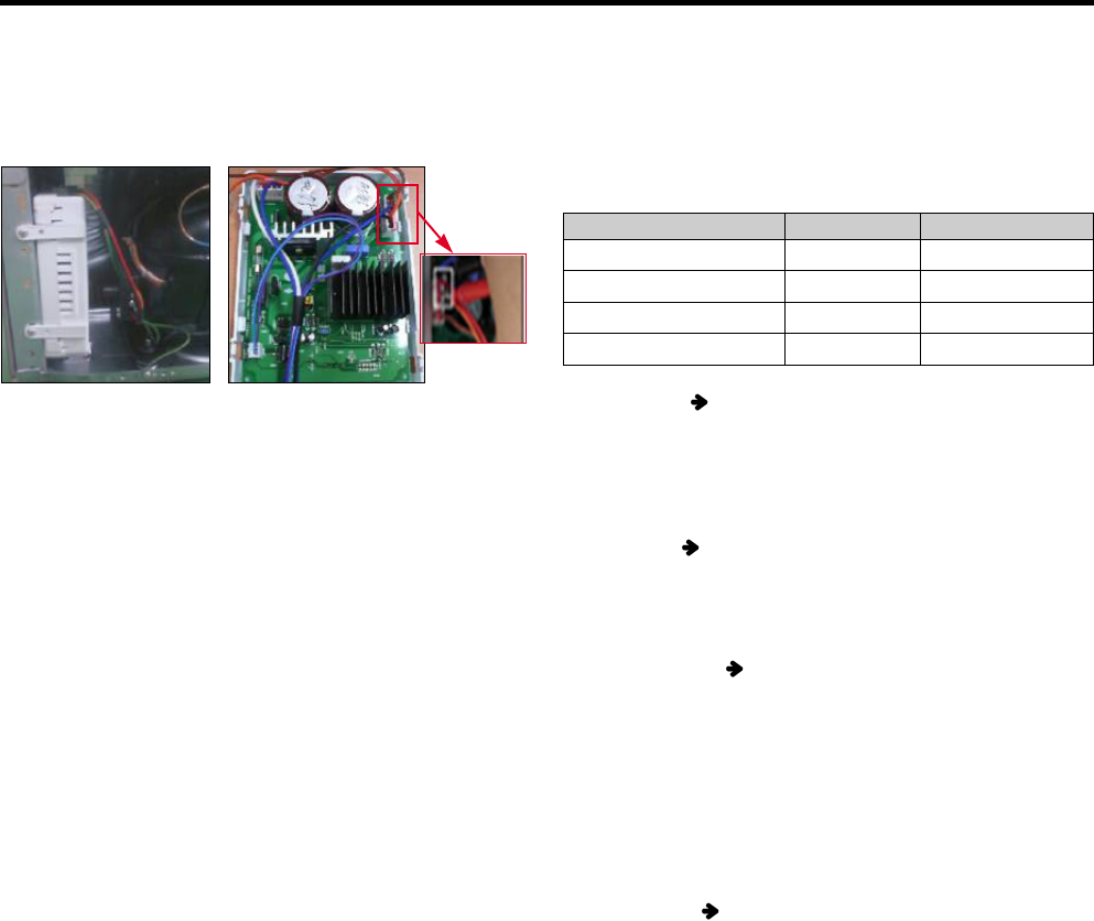
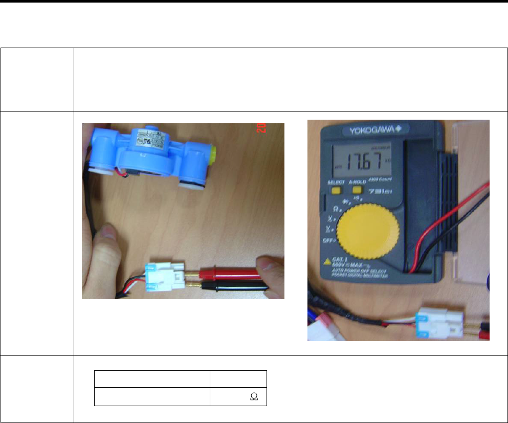
Measure the resistance between pin of the connector (as
shown picture) with a multi-tester.
Standard for normality
-In order to decide whether compressor operating is normal
or not, check the output transfer during the refrigerator
operation.
-After input the initial power and compressor operates, wait
for 10 minutes to estimate.
-Compressor operation may be diagnosed as normal if the
voltage falls between 145V and 180V.
Warning
1. Please be cautious of electric shock and short (it is
estimated after turning on initial power).
2. If the voltage is estimated less than 80V, it is diagnosed
as bad.
2) Check to normality by measurement of Voltage
If compressor protection logic is running, LED Lamp’s
blinking frequency of sub PCB, which takes in charge of
control, can help estimate the protection logic’s symptoms
and the cause of its problems.
Trip name
Stroke Trip
Current Trip
Lock Piston Trip
IPM fault trip
Led Times
2
6
5
7
Comp Off Time
1min
6min
2min 30sec
20sec
3) Check problems by LED On & Off Count _ (Sub PCB)
-Current Trip PCB defects or Cycle clogging maybe the
causes. After estimating winding resistance, estimate
compressor operation voltage to check if there is any
problem and take actions to repair cycle at replacement of
compressor.
-Stroke Trip can occur when the surrounding
temperature is high, C-Fan, F-Fan and so on are
constrained, or when cycle problems, such as moisture
blocking or compressor defect, are related.
-Lock Piston Trip Since compressor itself can be a
potential cause of a defect, estimate the compressor
resistance value according to #1’s compressor winding
value estimation method and estimate the #2’s
compressor operation voltage to decide whether it is
defective or not
(Before replacement of compressor, replace PCB and
conduct the replacement of compressor during
compressor replacement)
-IPM fault Trip Replace sub PCB since there is high
chance that it is caused by sub PCB’s part defect.
<Fig. 1> <Fig. 1>
- 21 -
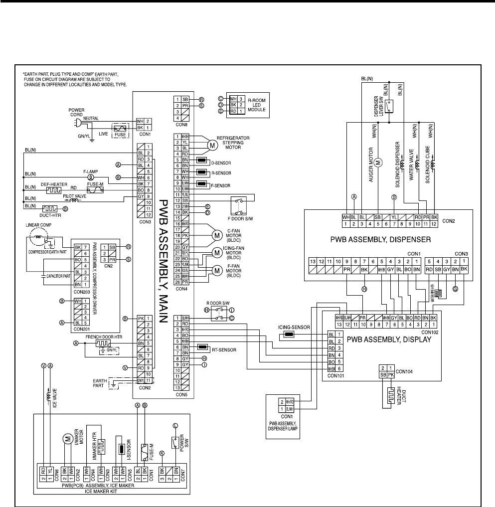
5. CIRCUIT DIAGRAM

- 22 -
6. TROUBLESHOOTING
NO Error Detection
Category
1Normality None Normal operation of Display
2Freezer Sensor
Error Er FS Short or Disconnection of
Freezer Sensor
3Refrigerator
Sensor Error Er rS Short or Disconnection of
Refrigerator Sensor Each Sensor have to check
disconnection
Error Generation Factors Remark
Error Display
Freezer
Temperature
Ref.
Temperature
4Defrosting Sensor
Error Er dS Short or Disconnection of
Defrosting Sensor
5Icing Sensor Error Er IS Short or Disconnection of
Icing Sensor
6Poor Defrosting Er dH
Even though it is passed
1hour since then Defrosting,
if Defrosting sensor is not
over 46°F(8°C), it is caused
Temperature Fuse
Disconnection, Heater
disconnection, DRAIN Jam,
Poor Relay for Heater
7
Abnormality of
Brushless DC
FAN Motor for Ice
Making
Er IF
It is caused when F/B signal
isn’t over 65 seconds during
Brushless DC FAN motor
operating
Poor BLDC Motor connection,
DRIVE IC, and TR
8
Abnormality of
Brushless DC
FAN Motor for
Freezer
Er FF
It is caused when F/B signal
isn’t over 65seconds during
Brushless DC FAN motor
operating
Poor BLDC Motor connection,
DRIVE IC, and TR
9
Abnormality of
Brushless DC
FAN Motor for
Mechanic Room
Er CF
It is caused when F/B signal
isn’t over 65seconds during
Brushless DC FAN motor
operating
Poor BLDC Motor connection,
DRIVE IC, and TR
10 Communication
Error Er CO
Communication Error
between Micom of Main PCB
and Display Micom
Poor Communication
connection, Poor TR of
Transmitter and Receiver
ERROR CODE on display panel
NOTE) In the case of Room Temperature Seneor Error, “Er rt” appears on the Display when Ultra Ice KEY and Freezer
Temp’ KEY pressed at the same time for one second.
- 23 -
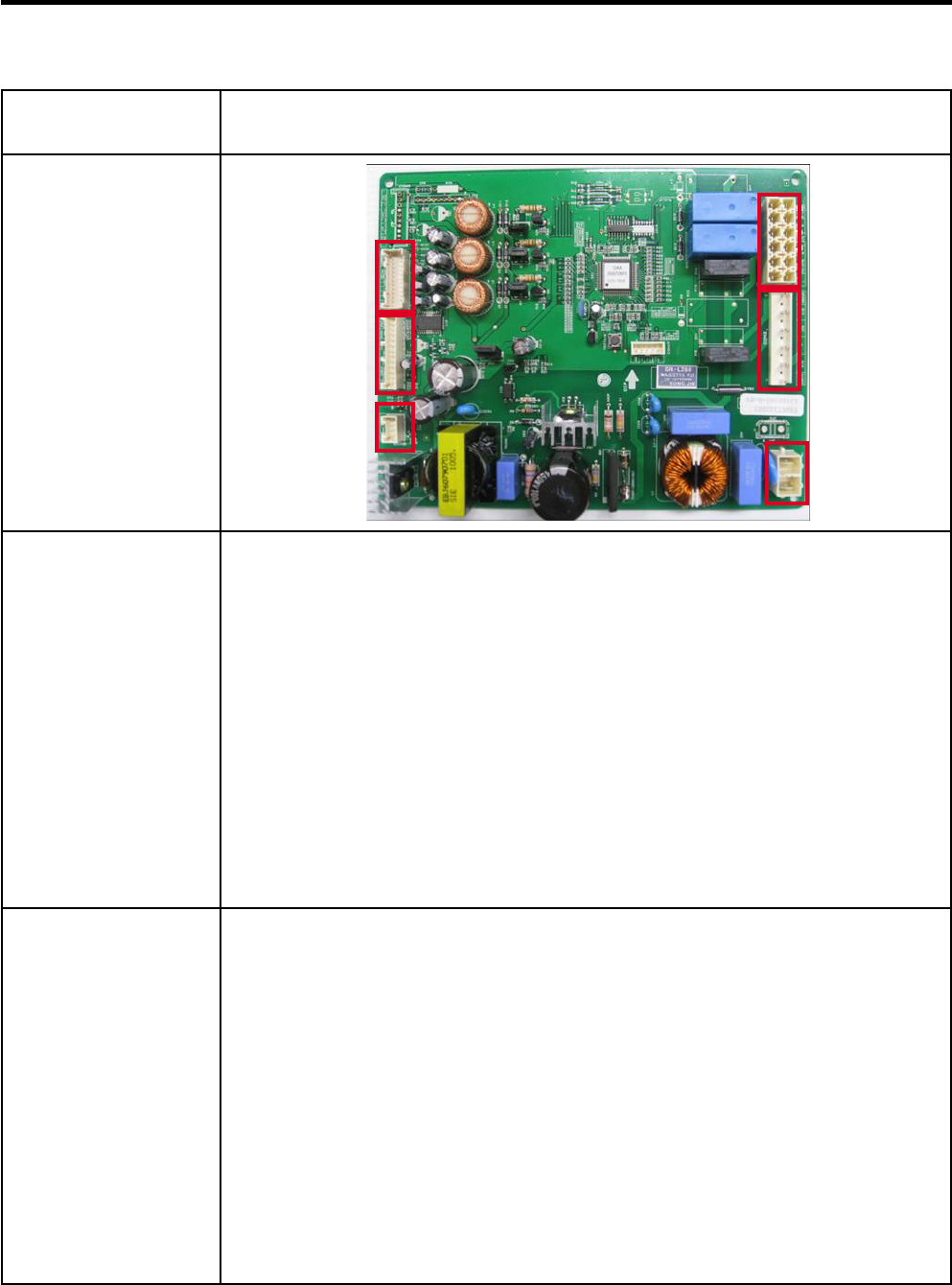
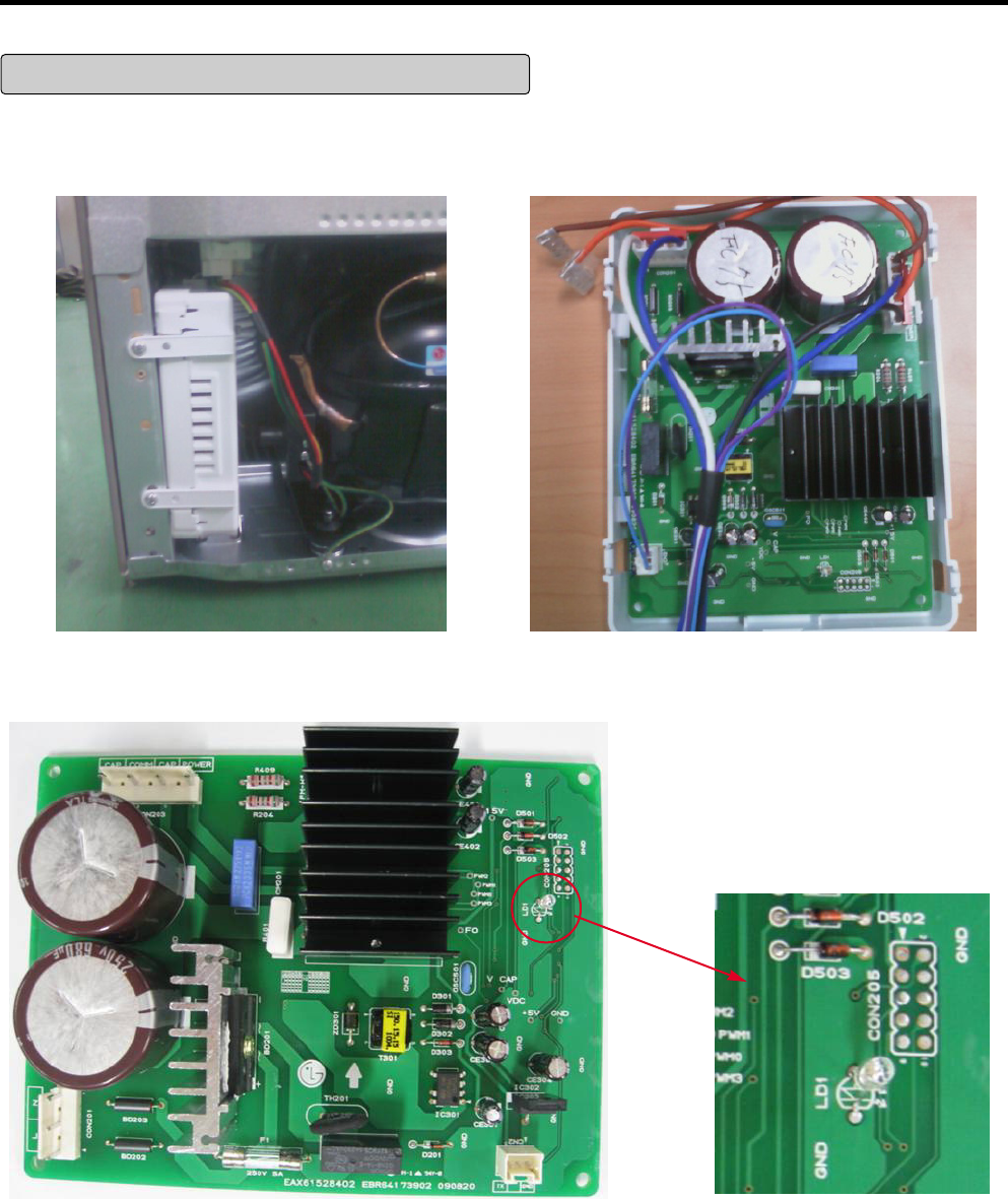
7. PCB Picture
7-1 Main PCB
P/No & MFG
EBR67348003
(2010.02~)
Picture
CON4
CON5
CON8
CON3
CON2
CON1
- 24 -
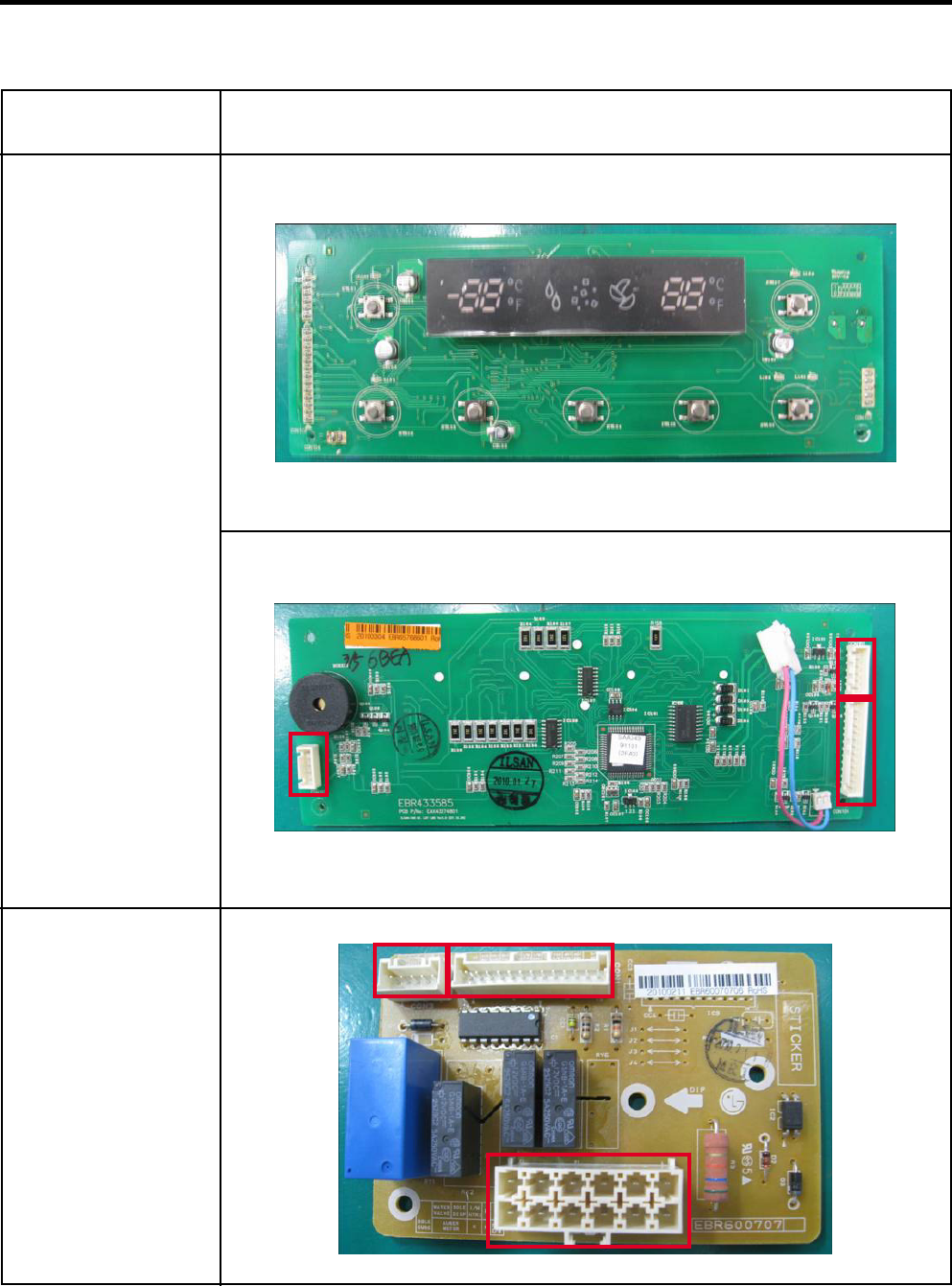
CON2
7-2 Display PCB & Sub PCB
P/No
Display PCB
EBR43358505
(2010.02~)
Sub PCB
EBR60070706
(2010.02~)
Picture
CON3 CON1
CON102 CON104
CON101
- 25 -
0
Infinite
ohms
See
resistance
table
Short
Open
Normal
Change the sensor
Replace the
refrigerator
Check the Temp and
resistance (Table-1)
Result SVC Action
8. Troubleshooting With Error Display
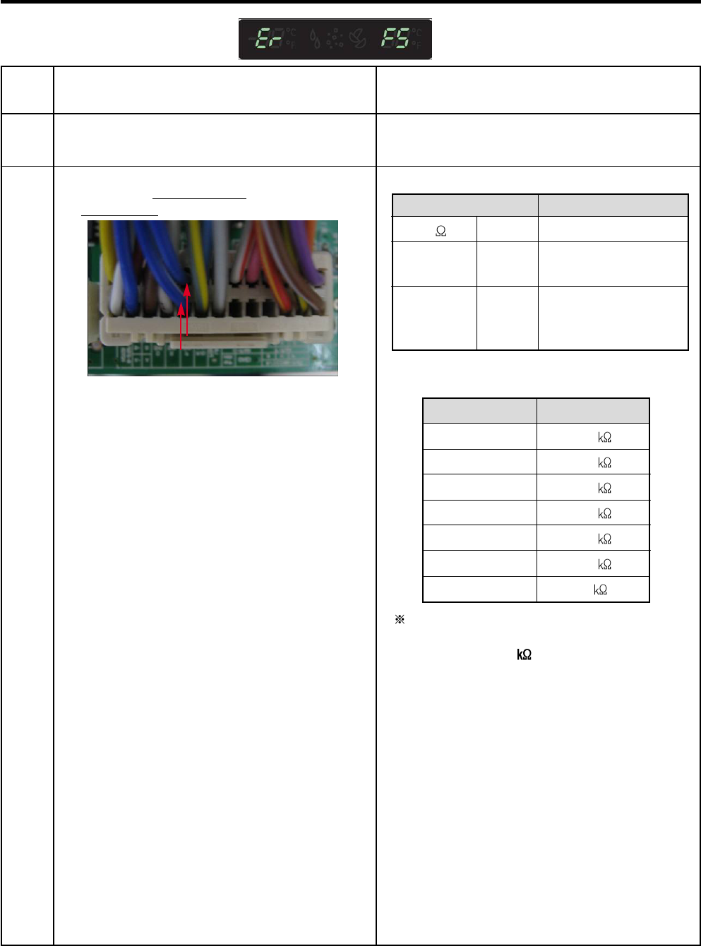
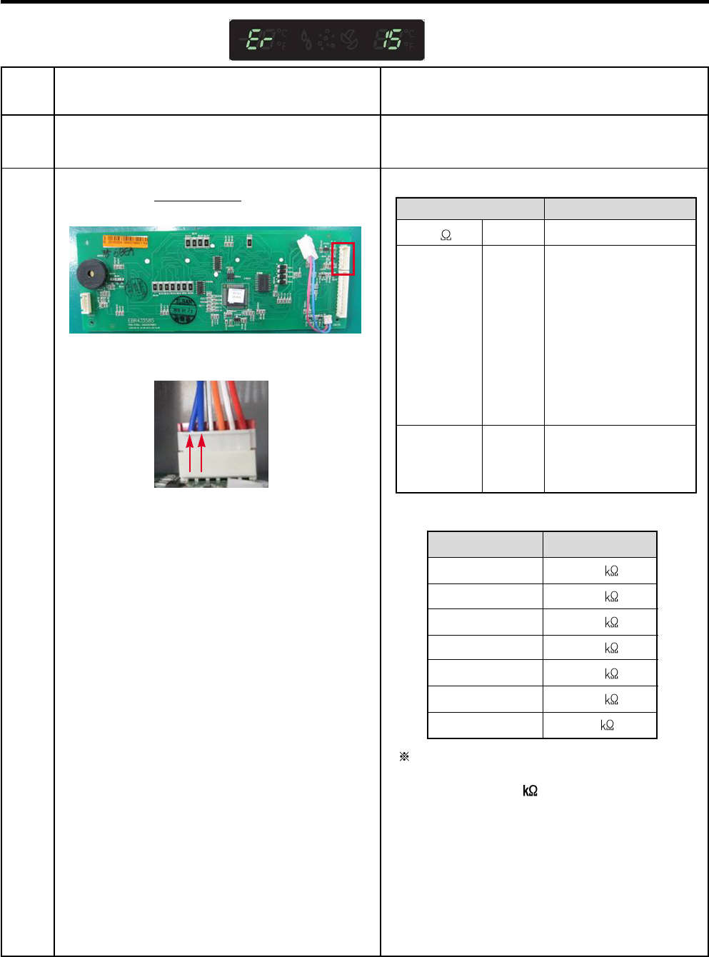
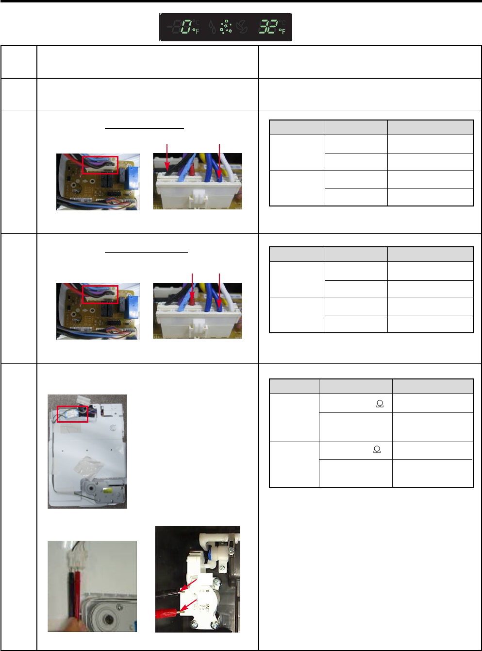
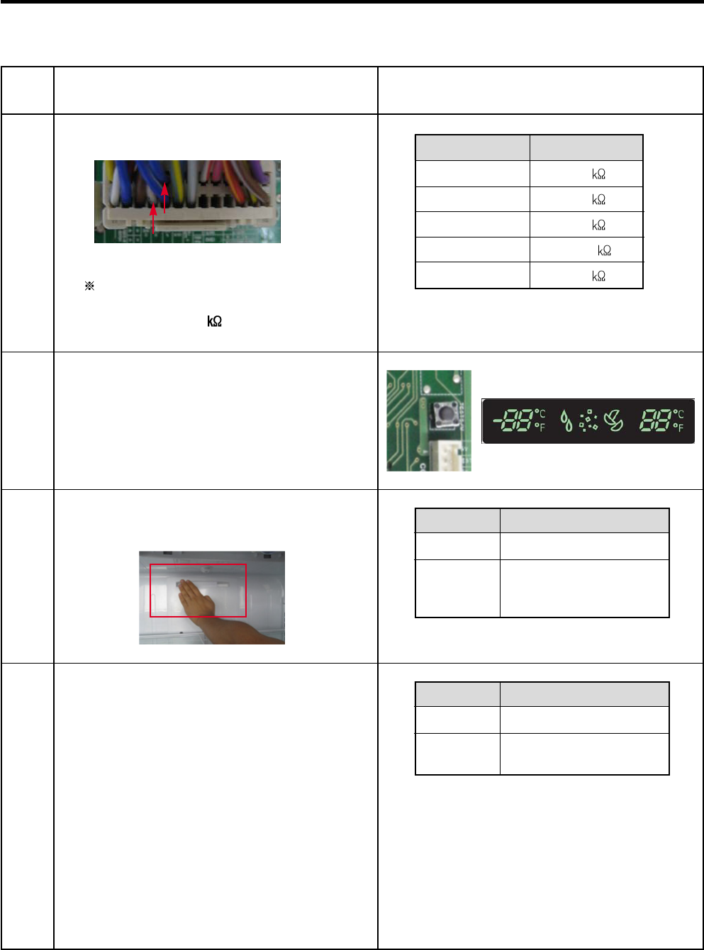
8-1 Freezer Sensor Error (Er FS)
No
1
2
Checking flow
Check for a loose connection.
Check the Blue/White to
Blue/White.
Result & SVC Action
<CON4> <Temperature table-1>
(1) To (2)
-22°F / -30°C
-13°F / -25°C
-4°F / -20°C
5°F / -15°C
14°F / -10°C
23°F / -5°C
32°F / 0°C
Result
40
30
23
17
13
10
8
The sensor is determined by
the temperature.
For example, 23 indicates -4°F.
- 26 -
8-2 Refrigerator Sensor Error (Er rS)
No
1
2
Checking flow
Check for a loose connection.
Check the White to White.
Result & SVC Action
<Temperature table-2>
(1) To (2)
23°F / -5°C
32°F / 0°C
41°F / 5°C
50°F / 10°C
59°F / 15°C
Result
38
30
24
19.5
16
The sensor is determined by
the temperature.
For example, 30 indicates 32°F.
<CON4>
0
Infinite
ohms
See
resistance
table
Short
Open
Normal
Change the sensor
Replace the
refrigerator
Check the Temp and
resistance (Table-2)
Result SVC Action
- 27 -
8-3 Icing Sensor Error (Er IS)
No
1
2
Checking flow
Check for a loose connection.
Check the Blue to Blue.
Result & SVC Action
<Temperature table-1>
(1) To (2)
-22°F / -30°C
-13°F / -25°C
-4°F / -20°C
5°F / -15°C
14°F / -10°C
23°F / -5°C
32°F / 0°C
Result
40
30
23
17
13
10
8
The sensor is determined by
the temperature.
For example, 23 indicates -4°F.
<CON101>
<Display>
<CON101> 0
Infinite
ohms
See
resistance
table
Short
Open
Normal
Change the sensor
Check the resistance
of the defrost sensor
wires back to the
main PCB. If they are
open between the
Main PCB and the
connector for the
icemaker it will be
necessary to replace
the refrigerator.
Check the Temp and
resistance (Table-1)
Result SVC Action
<Temperature table-3>
(1) To (2)
-22°F / -30°C
-13°F / -25°C
-4°F / -20°C
5°F / -15°C
14°F / -10°C
23°F / -5°C
32°F / 0°C
Result
40
30
23
17
13
10
8
- 28 -
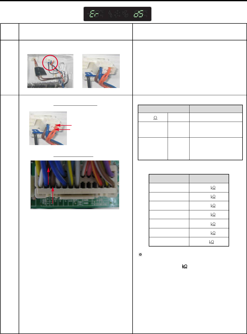
8-4 Defrost Sensor Error (F dS)
No
1
2
Checking flow
Check for a loose connection.
Check the Orange to Orange.
Result & SVC Action
Check the Brown to Brown.
<CON4>
The sensor is determined by
the temperature.
For example, 23 indicates -4°F.
0
Infinite
ohms
See
resistance
table
Short
Open
Normal
Change the sensor
Replace the
refrigerator
Check the Temp and
resistance (Table-3)
Result SVC Action
- 29 -
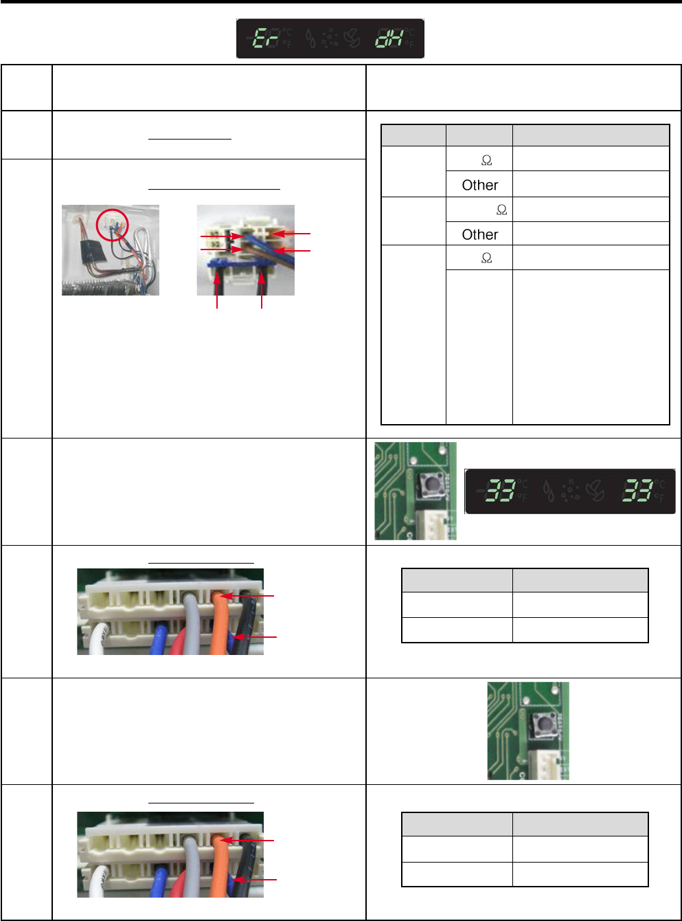
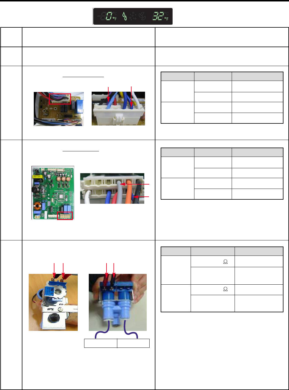
8-5 Defrost Heater Error (Er dH)
No
1
2
Checking flow
Check the Door gasket.
Check the Defrost control part.
3Input Test 3 Mode.
(Push the button 3 times)
4Check the Blue to Orange.
Result & SVC Action
Fuse
M
Defrost Heater
Defrost
Sensor
5Release the test mode.
Push the button 1 times. (Normal)
<CON3>
<CON3>
Result
112 ~ 116 V
0 V
SVC Action
Go to the 5
Replace Main PCB
6Check the Blue to Orange.
Result
0 V
112 ~ 116 V
SVC Action
Normal
Replace Main PCB
Fuse-M
Defrost
Heater
Defrost
Sensor
0
34~42
0
Infinite
ohms
Go to the 3
Change Fuse-M
Go to the 3
Change Fuse-M
Go to the 3
Check the resistance of
the defrost sensor wires
back to the main PCB.
If they are open
between the Main PCB
and the connector for
the icemaker it will be
necessary to replace
the refrigerator.
Part Result SVC Action
- 30 -
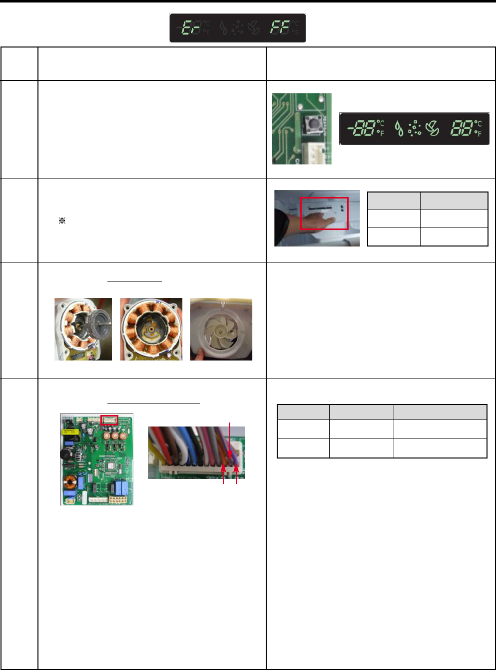
8-6 Freezer Fan Error (Er FF)
No
1
2
Checking flow
Reset the unit and
Input Test 1 Mode.
(Push the button 1 time)
Open the freezer door and Check the air
flow.
While an error code is displayed,
the fan is not working.
3Check the Fan motor. Rotate fan using your hand.
It feel stuck or locked up, change the motor.
(Cause of ice or rust inside of motor)
4Check the Fan motor voltage.
Result & SVC Action
Below 12 V
0 or 5 V
(1) ~ (2)
(2) ~ (3)
Change the PCB
Change the motor
Point Result SVC Action
<CON4>
Status
No airflow
Airflow
SVC Action
Go to 3
Go to 4
(1)
(2)
(3)
- 31 -
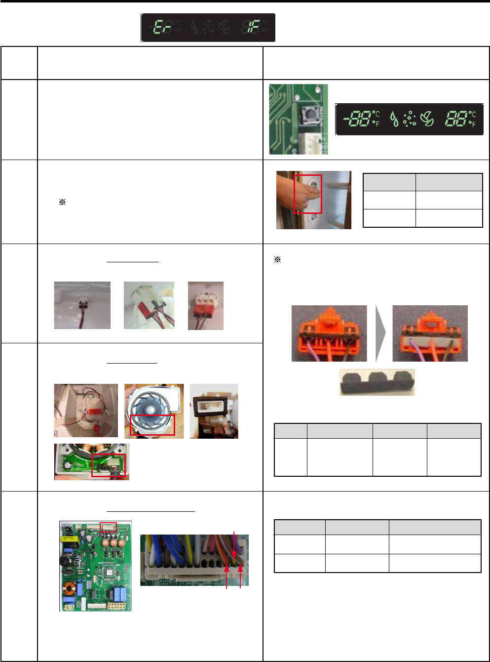
8-7 Icing Fan Error (Er IF)
No
1
2
Checking flow
Reset the unit and
Input Test 1 Mode.
(Push the button 1 time)
Open the refrigerator door and Check the
air flow.
While an error code is displayed,
the fan is not working.
3Check the Connector.
(Frozen caused the PCB short)
Tip
To protect ice short, add wire seal in
connector. We developed new type
connector, so order the new type.
4Check the Fan motor.
(Frozen, Lock, ect.)
Result & SVC Action
5Check the Fan motor voltage.
Below 9 V
0 or 5 V
(1) ~ (2)
(2) ~ (3)
Change the PCB
Change the motor
Result SVC Action
Duct Asm,
Connector
407A 5209JA
1044A
5209JA
1044A
Part Name Old P/No New P/NoNo
Status
No airflow
Airflow
SVC Action
Go to the 3,4
Go to the 5
Wire seal (Silicon)
<CON4> (1)
(2)
(3)
- 32 -
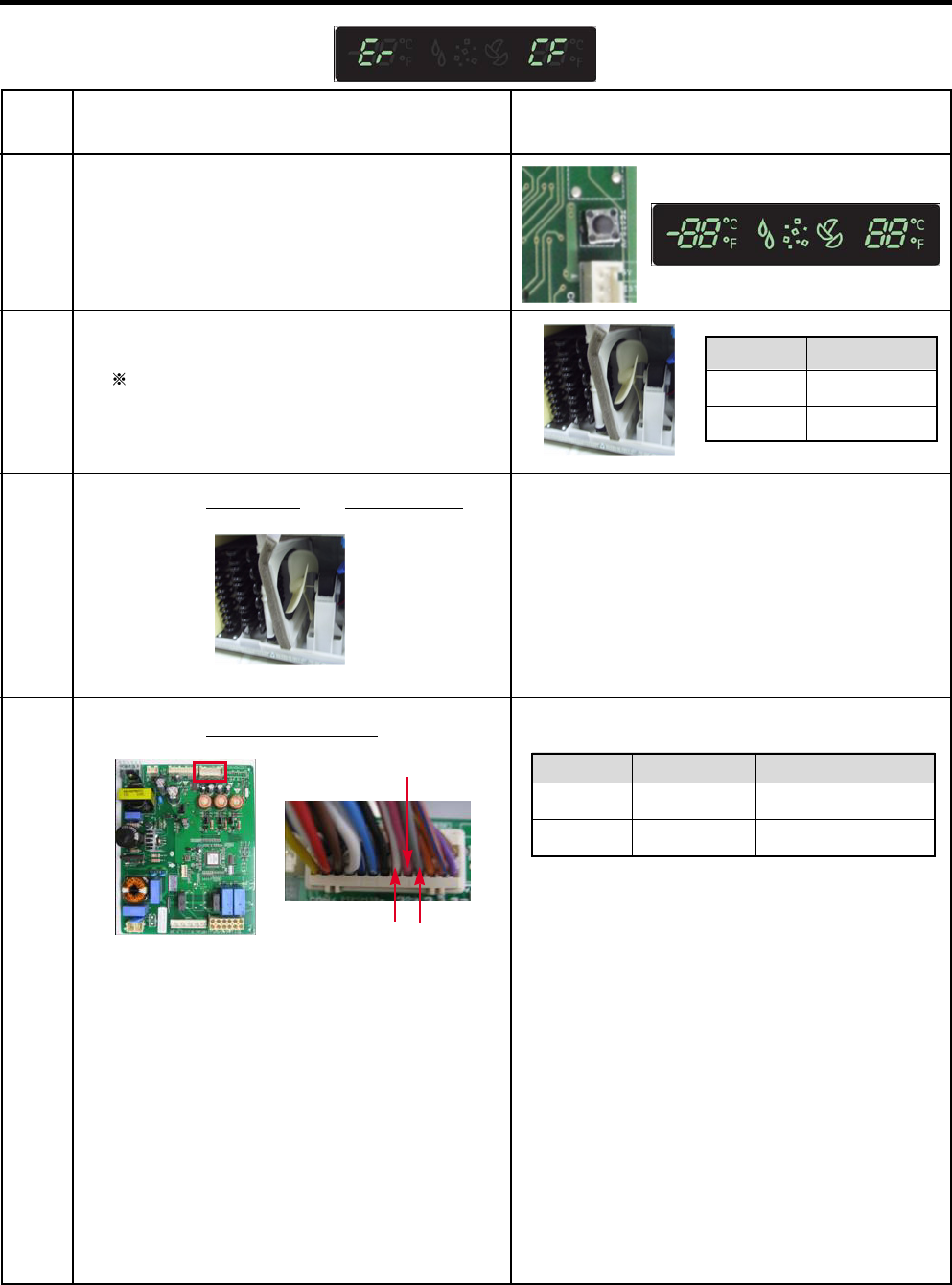
8-8 Condenser Fan Error (Er CF)
No
1
2
Checking flow
Reset the unit and
Input Test 1 Mode.
(Push the button 1 time)
Check the fan rotating.
While an error code is displayed,
the fan is not working.
3Check the Fan motor and surrounding. Rotate fan using your hand.
It feel stuck or locked up, change the motor.
Result & SVC Action
4Check the Fan motor voltage.
Below 10 V
0 or 5 V
(1) ~ (2)
(2) ~ (3)
Change the PCB
Change the motor
Result SVC Action
Status
No airflow
Airflow
SVC Action
Check motor
Go to the 4
<CON4>
(1)(2) (3)
- 33 -
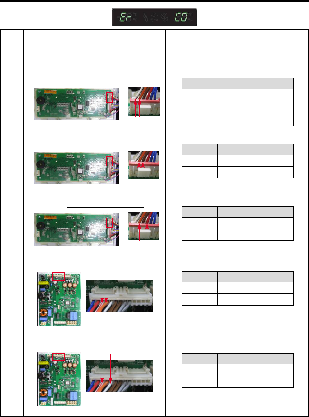
8-9 Communication Error (Er CO)
No
1
2
Checking flow
Check the loose connection.
Check the Red to White/Red.
Result & SVC Action
Result
12 V
Other
SVC Action
Go to the 3
Check the Hinge
(loose connection)
Change the Main PCB
5Check the White/Red to Orange.
<CON5>
6Check the White/Red to White/Black.
<CON5>
<CON101><Display>
CON0101
3Check the Orange to White/Red.
Result
0 V or 5 V
Other
SVC Action
Change the Display PCB
Go to the 4
4Check the White/Black to White/Red.
Result
0 V or 5 V
Other
SVC Action
Change the Main PCB
Go to the 5
Result
0 V or 5 V
Other
SVC Action
Change the Display PCB
Go to the 6
Result
0 V or 5 V
Other
SVC Action
Change the Main PCB
Normal
CON0101
CON0101
<CON101><Display>
<CON101><Display>
- 34 -
9. Troubleshooting Without Error Display
9-1 Cube mode doesn’t work
No
1
2
Checking flow
Check the loose connection.
Check the Black to Blue.
(While pushing the lever S/W)
Result & SVC Action
<CON2>
3Check the Red to Blue.
(While pushing the lever S/W)
4Check the resistance value.
<Ice Maker>
<Geared Motor> <Dispenser Motor>
(2)(1) (3)
(4)
Activated
Not
activated
112 ~ 115 V
Other
0 ~ 2 V
Other
Go to the 3
Change PCB
Go to the 3
Change PCB
Lever s/w Result SVC Action
Activated
Not
activated
9 ~ 12 V
Other
0 ~ 2 V
Other
Go to the 4
Change PCB
Go to the 4
Change PCB
Lever s/w Result SVC Action
(1) to (2)
(3) to (4)
31.1 ~ 42.1
Other
9.9 ~ 12.1
Other
Normal
Replace
Geared Motor
Normal
Replace
Geared Motor
Point Result SVC Action
<CON2>
- 35 -
9-2 Crush mode doesn’t work
No
1
2
Checking flow
Check the loose connection.
Check the Sky Blue to Blue.
(While pushing the lever S/W)
Result & SVC Action
3Check the Red to White Red.
(While pushing the lever S/W)
4Check the resistance value.
<Ice Maker>
<Dispenser Motor><Geared Motor>
(2)(1) (3)
(4)
Activated
Not
activated
112 ~ 115 V
Other
0 ~ 2 V
Other
Go to the 3
Change PCB
Go to the 3
Change PCB
Lever s/w Result SVC Action
Activated
Not
activated
9 ~ 12 V
Other
0 ~ 2 V
Other
Go to the 4
Change PCB
Go to the 4
Change PCB
Lever s/w Result SVC Action
(1) to (2)
(3) to (4)
31.1 ~ 42.1
Other
9.9 ~ 12.1
Other
Normal
Replace
Geared Motor
Normal
Replace
Geared Motor
Point Result SVC Action
<CON2>
<CON2>
- 36 -
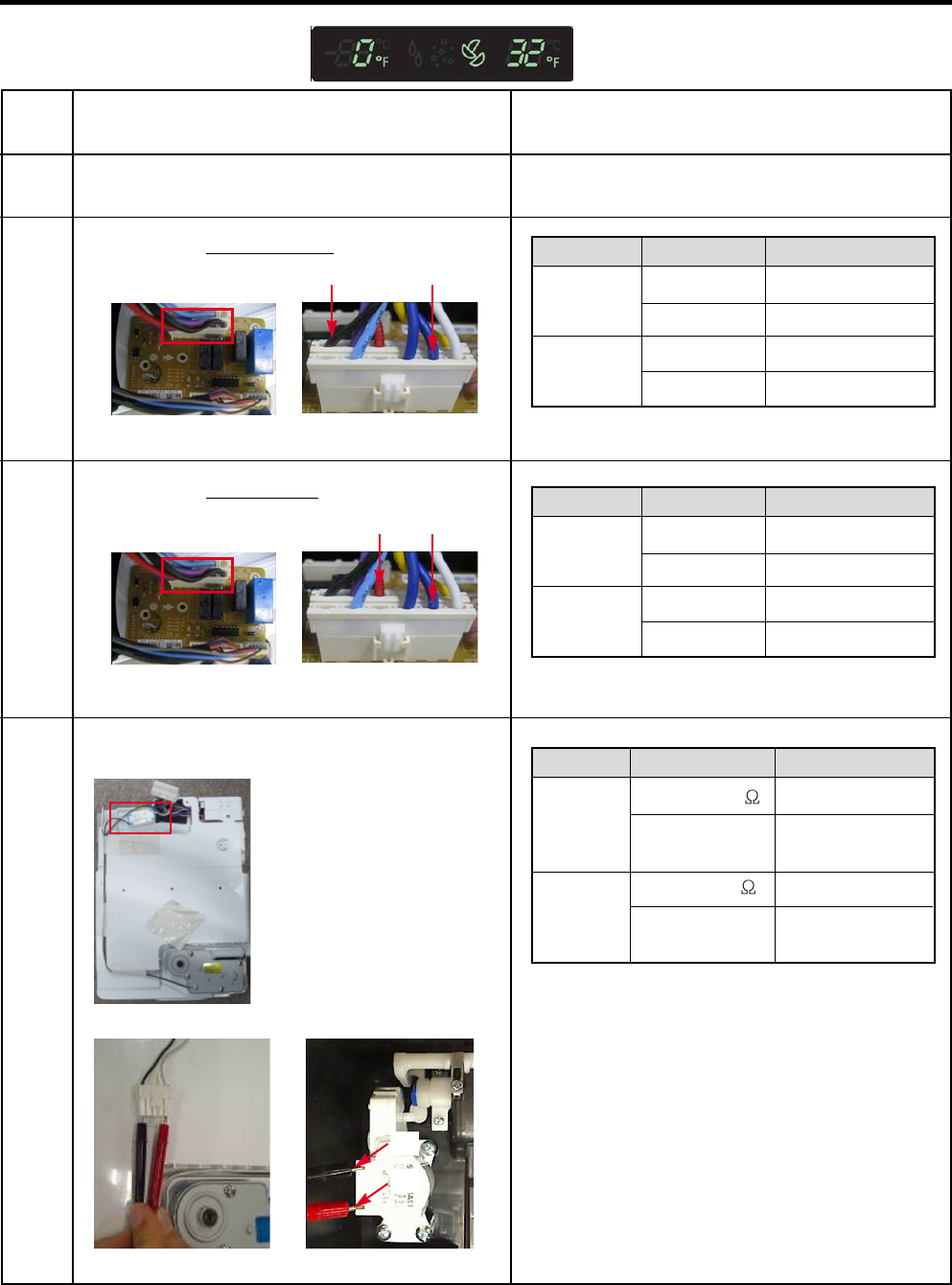
9-3 Water mode doesn’t work
No
1
2
Checking flow
Check the loose connection.
Check the Purple to Blue.
(While pushing the lever S/W)
Result & SVC Action
3Check the Blue to Gray.
(While pushing the lever S/W)
4Check the resistance value.
<Pilot Valve>
Machine Room
<Water Valve>
In door
Activated
Not
activated
112 ~ 115 V
Other
0 ~ 2 V
Other
Go to the 3
Change PCB
Go to the 3
Change PCB
Lever s/w Result SVC Action
Activated
Not
activated
112 ~ 115 V
Other
0 ~ 2 V
Other
Go to the 4
Change PCB
Go to the 4
Change PCB
Lever s/w Result SVC Action
(1) to (2)
(3) to (4)
360 ~ 420
Other
360 ~ 420
Other
Normal
Replace
Water Valve
Normal
Replace
Water Valve
Point Result SVC Action
(1) (2) (3) (4)
Dispenser Ice Maker
<CON3>
<CON2>
- 37 -
9-4 Freezer room AC Bulb Lamp doesn’t work
No
1
Checking flow
Check the Freezer door switch. If feel sticky, Change the door s/w.
Result & SVC Action
2Check the door S/W resistance.
3Check the Yellow Blue to Sky blue.
4Check the Blue to Black. Check the Blue to Black.
Closed
Open
0 ~ 2 V
Other
115 V
Other
Normal
Change the Main PCB
Change the F Lamp
Change the PCB
Status Result SVC Action
Closed
Open
5 V
Other
0 V
Other
Go to the 4
Change the Door S/W
Go to the 4
Change the Door S/W
Status Result SVC Action
Normal
Push
S/W
0
Other
Infinity
Go to the 3
Change door S/W
Go to the 3
Change door S/W
Status Result SVC Action
<CON4>
<CON3>
- 38 -
9-5 Refrigerator room lamp doesn’t work
No
1
Checking flow
Check the Refrigerator door switch. If feel sticky, Change the door s/w.
Result & SVC Action
2Check the door S/W resistance.
3Check the Black to Gray White.
4Check the Red to Black.
Closed
Open
0 ~ 2 V
Other
12 V
Other
Normal
Change the Door S/W
Normal
Change the LED Lamp
Status Result SVC Action
Normal
Push
S/W
0
Other
Infinity
Other
Go to the 3
Change door S/W
Go to the 3
Change door S/W
Status Result SVC Action
Normal 12 V
Other
Go to the 4
Change the PCB
Status Result SVC Action
Normal 12 V
Other
Go to the 5
Change the LED Lamp
Status Result SVC Action
5Check the Black to White.
<CON4>
- 39 -
9-6 Poor cooling in Fresh food section
No
1
Checking flow
Check the sensor resistance.
2Reset the unit and
Input Test 1 Mode.
(Push the button 1 time)
3Open the fresh food door and
Check the air flow.
The sensor is determined by
the temperature.
For example, 30 indicates 32°F.
Result & SVC Action
<CON4>
Temperature
23°F / -5°C
32°F / 0°C
41°F / 5°C
50°F / 10°C
59°F / 15°C
Result
38
30
24
19.5
16
Status
Airflow
No airflow
SVC Action
Go to the 4
Check the R Fan motor
Check the damper
(Go to the 6)
4Check the air temperature.
Cold or not? Status
Cold
Not cold
SVC Action
Normal
Check the Compressor
And sealed system
- 40 -
No
5
Checking flow
Damper checking method.
Inputting TEST Mode,
Check the damper and PCB.
6Check the Fan motor.
Rotate fan using your hand.
It feel stuck or locked up, change the
motor.
(Cause of ice or rust inside of motor)
Result & SVC Action
7Check the F Fan motor voltage.
(1)(3)
(2) (4)
Open
Closed
Not
working
1 Mode
2 Mode
1,2
mode
Damper is normal.
(Check the Damper)
Change the damper
Test
Mode
Damper
State SVC Action
(1) to (2)
(3) to (4)
270 ~330
Other
270 ~330
Other
Normal
Change damper
Normal
Change damper
Test Point Result SVC Action
Below 12 V
0 or 5 V
(1) ~ (2)
(2) ~ (3)
Change the PCB
Change the motor
Point Result SVC Action
StuckMotor Change the motor
Point Result SVC Action
<CON4>
(1)
(2)
(3)
- 41 -
9-7 Poor cooling in Freezer compratment
No
1
Checking flow
Check the sensor resistance.
2Reset the unit and
Input Test 1 Mode.
(Push the button 1 time)
3Open the freezer door and check the air
flow.
The sensor is determined by
the temperature.
For example, 23 indicates -4°F.
Result & SVC Action
Status
Airflow
No airflow
SVC Action
Go to the 4
Check the F Fan motor
4Check the air temperature.
Cold or not ? Status
Cold
Not cold
SVC Action
Normal
Check the Compressor
And sealed system
(1) To (2)
-22°F / -30°C
-13°F / -25°C
-4°F / -20°C
5°F / -15°C
14°F / -10°C
23°F / -5°C
32°F / 0°C
Result
40
30
23
17
13
10
8
<CON4>
- 42 -
(1) to (2)
(3) to (4)
270 ~330
Other
270 ~330
Other
Normal
Change damper
Normal
Change damper
Point Result SVC Action
9-8 Over cooling in Fresh food compartment
No
1
Checking flow
Check the sensor resistance.
2Reset the unit and
Input Test 1 Mode.
(Push the button 1 time)
3Open the refrigerator door and
Check the air flow.
The sensor is determined by
the temperature.
For example, 30 indicates 32°F.
Result & SVC Action
Temperature
23°F / -5°C
32°F / 0°C
41°F / 5°C
50°F / 10°C
59°F / 15°C
Result
38
30
24
19.5
16
Status
Airflow
No airflow
SVC Action
Go to the 4
Check the R Fan
Check the damper
(Go to the 5)
4Input Test 2 Mode and
Check the air flow.
(Push the button 1 time)
5Check the damper resistance.
Status
Airflow
No airflow
SVC Action
Go to the 5
Normal
(1)(3)
(2) (4)
<CON4>
- 43 -
After measure the values, you should put in the TPA again.
10. Reference
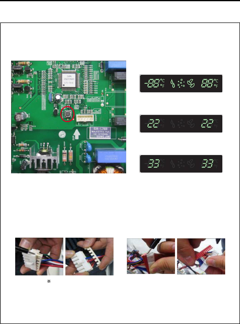
10-1 TEST MODE and Removing TPA
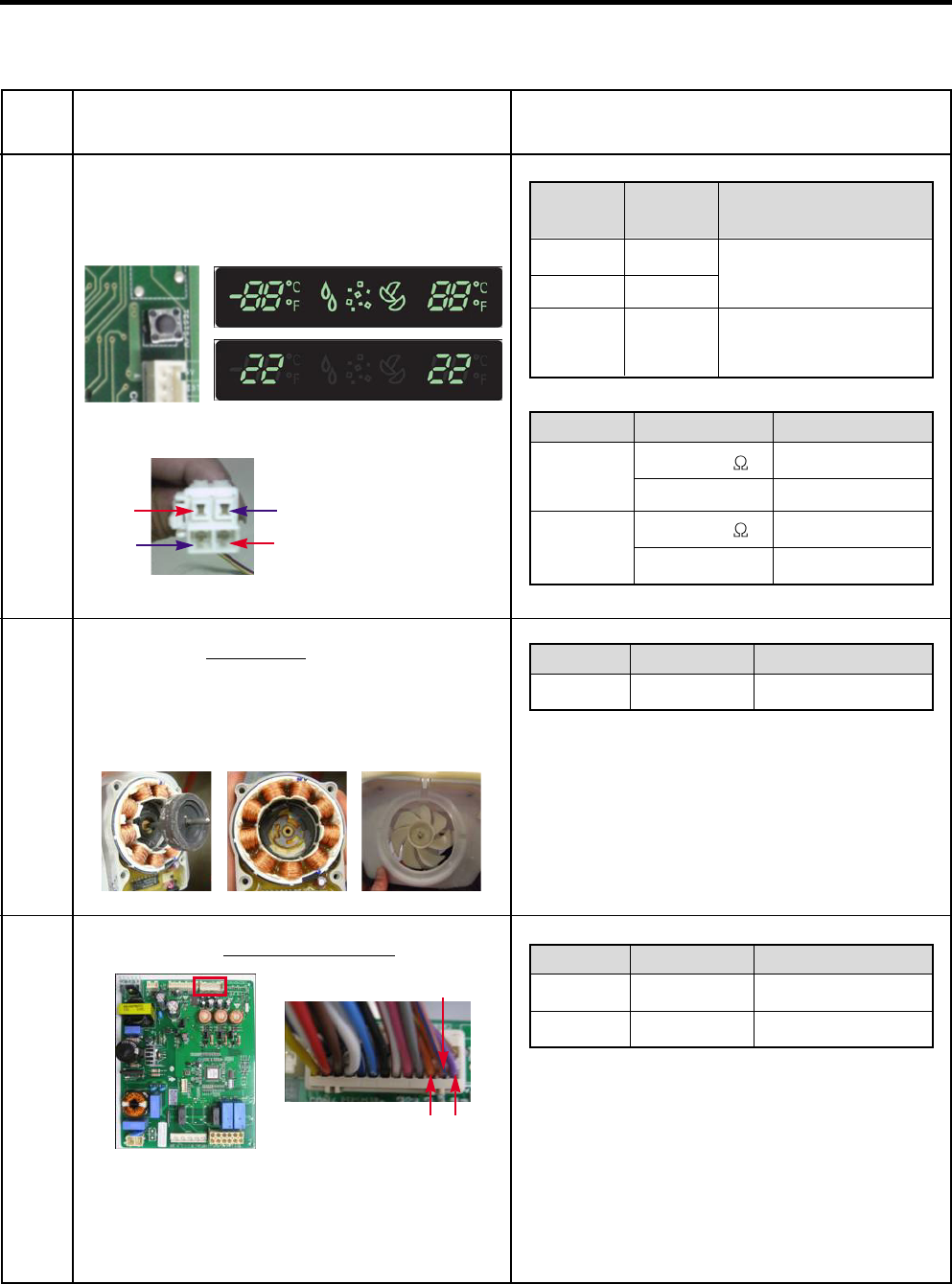
1. How to enter the TEST MODE
If you push the test button on the Main PCB, the refrigerator will be enter the TEST MODE.
2. How to remove Terminal Position Assurance (TPA)
* 1 time : Comp / Damper / All FAN on
(All things displayed)
Main PWB
<AC TPA> <DC TPA>
* 2 times : Damper closed
(22 22 displayed)
* 3 times : Forced defrost mode
(33 33 displayed)
- 44 -
10-2 TEMPERATURE CHART - FREEZER AND ICING SENSOR
TEMP
-39°F (-40°C)
-30°F (-35°C)
-21°F (-30°C)
-13°F (-25°C)
-4°F (-20°C)
5°F (-15°C)
14°F (-10°C)
23°F (-5°C)
32°F (0°C)
41°F (5°C)
50°F (10°C)
59°F (15°C)
68°F (20°C)
77°F (25°C)
86°F (30°C)
95°F (35°C)
104°F (40°C)
RESISTANCE
73.29
53.63
39.66
29.62
22.33
16.99
13.05
10.10
7.88
6.19
4.91
3.91
3.14
2.54
2.07
1.69
1.39
VOLTAGE
4.09 V
3.84 V
3.55 V
3.23 V
2.89 V
2.56 V
2.23 V
1.92 V
1.63 V
1.38 V
1.16 V
0.97 V
0.81 V
0.67 V
0.56 V
0.47 V
0.39 V
- 45 -
10-3 TEMPERATURE CHART - REFRIGERATOR AND DEFROST SENSOR
TEMP
-39°F (-40°C)
-30°F (-35°C)
-21°F (-30°C)
-13°F (-25°C)
-4°F (-20°C)
5°F (-15°C)
14°F (-10°C)
23°F (-5°C)
32°F (0°C)
41°F (5°C)
50°F (10°C)
59°F (15°C)
68°F (20°C)
77°F (25°C)
86°F (30°C)
95°F (35°C)
104°F (40°C)
RESISTANCE
225.1
169.8
129.3
99.30
76.96
60.13
47.34
37.55
30
24.13
19.53
15.91
13.03
10.74
8.89
7.40
6.20
VOLTAGE
4.48 V
4.33 V
4.16 V
3.95 V
3.734 V
3.487 V
3.22 V
2.95 V
2.67 V
2.40 V
2.14 V
1.89 V
1.64 V
1.45 V
1.27 V
1.10 V
0.96 V
- 46 -
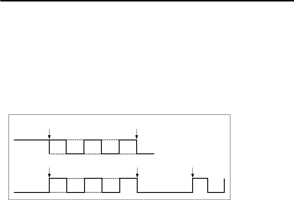
10-4 How to check the Fan-Error
(1) EBR673480
After sending a signal to the fan, the MICOM checks the BLDC fan
motor s lock status. If there is no feedback signal from the BLDC fan,
the fan motor stops for 10 seconds and then is powered again for 15
seconds. To determine that there is a fan motor malfunction,
this process is repeated 3 times. If the fan motor is determined to be
defective, the error code will be shown in the display for 30 minutes.
At this point, the process will be repeated until the fan motor operates
normally. If normal operation is achieved, the error display is erased and
the MICOM is reset automatically.
No signal Error Display
15s
10s
15s
10s
15s
Normal drive
No signal Repeat
20s
10s
15s
10s Pause 30min
Pause 30min 10s
15s 20s
- 47 -
Compressor Troubleshooting
Step 1) Loosen up screw of Case Assembly PCB and open
the Cover PCB
Step 2) Check for blinking frequency of LED, PWB
If compressor is normal, it does not blink
: Refer to the next page to find out what actions to take according to how many times LED blink
- 48 -
Actions to take according to Led blinking frequency
LED two - time repetiton (Stroke Trip)
on - on - off - on - on - off - on - on - off repeating
PCB Parts
defect or
Compress
or
Connector
miss
connecting
(Piston
over run)
1. Please check, Whether
connector of
compressor is attached
rightly or not. after
power off
2. After the first action,
You check on normal
operation of
compressor.
3. If the same symptom
arises after the second
action, replace PCB
Outlet
clogging
1. After resetting power,
check if it is running
normal
2. If the same symptom
arises after the first
action
3. If the same symptom
arises after the second
action, replace
compressor
Piston
constraint
1. After resetting power,
check if it is running
normal
2. If the same symptom
arises after the first
action
3. If the same symptom
arises after the second
action, replace
compressor
Circuit
over
current
error
Or cycle
error
1. After resetting power,
check if it is running
normal
2. If the same symptom
arises after the first
action
3. If the same symptom
arises after the second
action, replace
compressor
PCB parts
defect
(IPM)
1. After resetting power,
check if it is running
normal
2. If the same symptom
arises after the first
action, replace PCB
1
LED four - time repetiton (Overload Protect)
on - on - on - on - off - on - on - on - on - off repeating
2
LED five - time repetiton (Piston Lock Trip)
on - on - on - on - on - off - on - on - on - on - on - off repeating
3
LED six - time repetiton (Current Trip)
on
-
on
-
on
-
on
-
on
-
on
- off -
on
-
on
-
on
-
on
-
on
-
on
- off repeating
4
LED seven- time repetiton (IPM Fault Trip)
on - on - on - on - on - on - on - off - on - on -on - on - on - on- on - off repeating
5
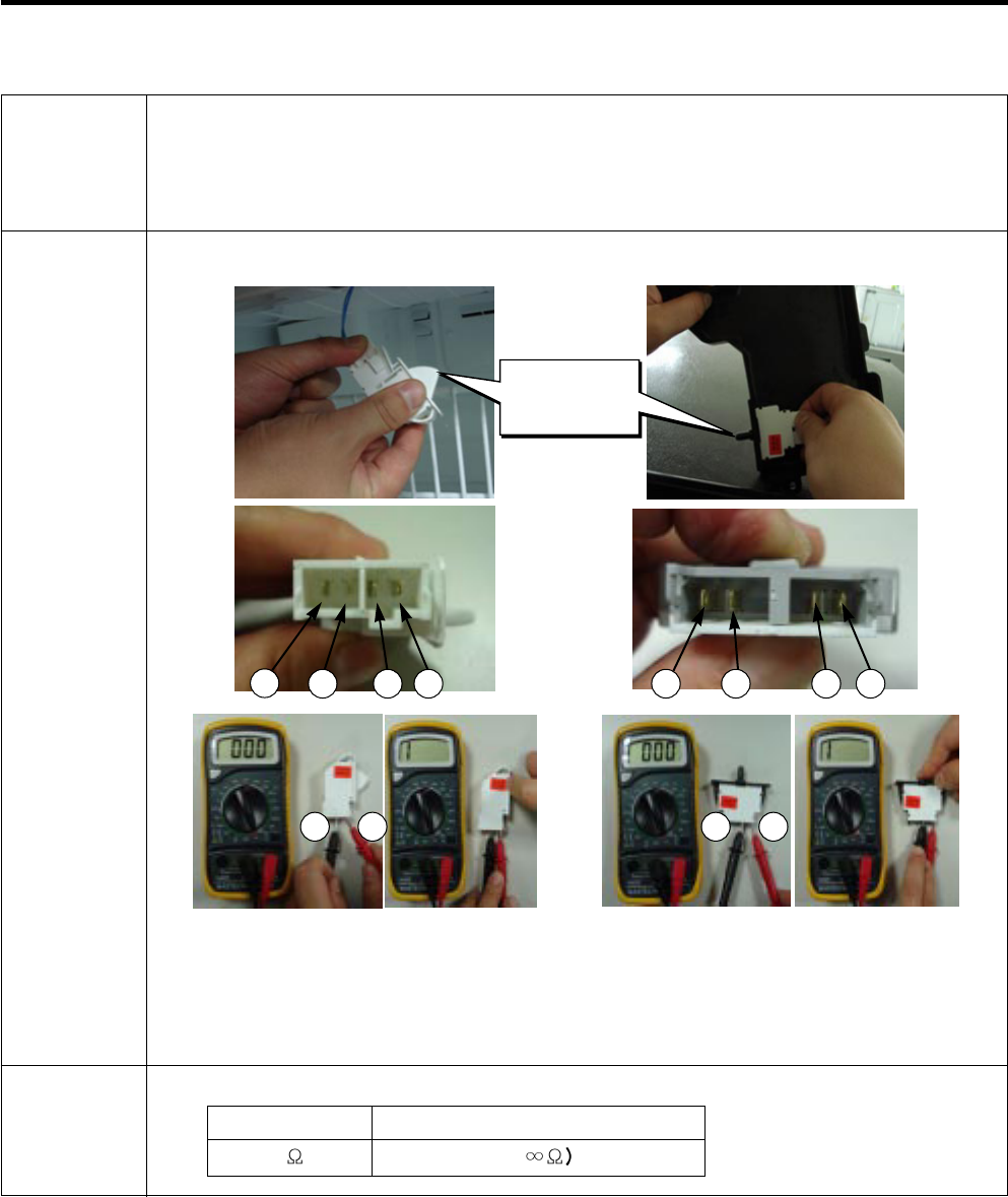
No LED operating condition Cause Service guideline

- 49 -
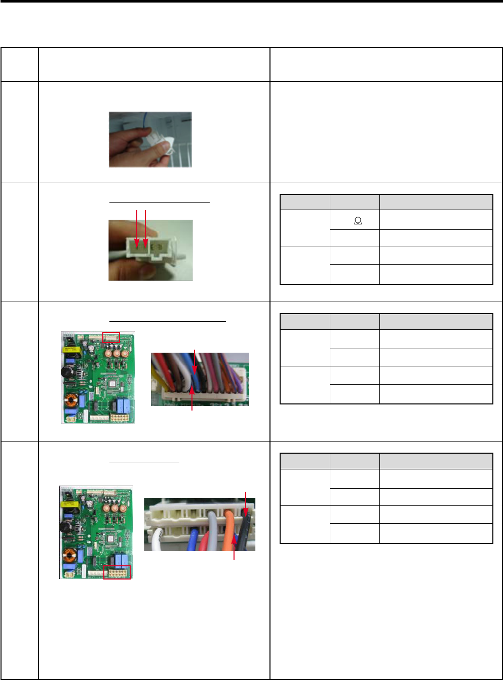
11. COMPONENT TESTING INFORMATION
11-1 Defrost Controller Assembly
Function -Controller assembly is consist of 2 kinds of part those are fuse-m and sensor. we can
decide part is defect or not when we check the resistance.
-Fuse-M can cut off the source when defrost heater operate the unusual high temperature.
-Sensor give temperature information to Micom
How to
Measure
(Fuse-M)
Measure the 2 pin connected to Fuse-M.
If the ohmmeter indicate below 0.1ohm
Fuse-M is good. If Fuse-M measures infinite
ohms, it is open and needs to be replaced.
How to
Measure
(Sensor)
Measure the 2 pin connected to Sensor.
If the ohmmeter indicate 11 (at room
temperature) It is normal.
Checking the resistance at other
temperatures, check the sensor resistance
chart.
Standard Sensor (at room temperature)
Test Point
(1) to (2)
Ressult
11
Fuse-M (at all temperature)
Test Point
(1) to (2)
Ressult
0 ~ 0.1
(1) to (2)
(1) to (2)
- 50 -
11-2 Sheath Heater
Function Sheath heater is a part for defrost.
How to
Measure
Measure the 2 pin connected to Sheath Heater.
If resistance is between 34 ~ 42 ohms, the heater is normal.
If it measures infinite ohms the heater is open and needs to be replaced.
Standard Sheath heater (at all temperature)
Test Point
(1) to (2)
Ressult
34 ~ 42
(1) (2)
- 51 -
11-3 Door Heater Assembly
Function The heater is designed to prevent the exterior moisture on the door.
How to
Measure
Standard Test Point
(1) to (2)
Ressult
2.3 ~ 2.9
1
2
3
5
8
9
4
6
7
- 52 -
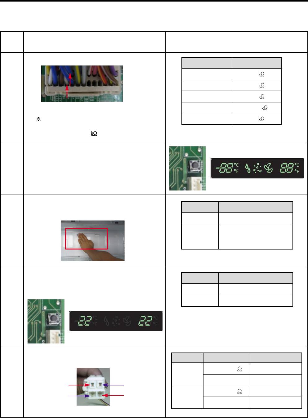
11-4 Door Switch
Function Senses when the door is opened or closed by sending a signal to the Main PCB.
How to
Measure
<Switch, Freezer> <Switch, Refrigerator>
Check the resistance between connectors 1, 2 and 3, 4.
Standard
Beep Beep
Multimeter beep – Switch F,R
Nomal
0
Push the button(Plunger)
None (
Button
(Plunger)
12 3 4
3 4 2 1
1 2 3 4
- 53 -
11-5 Dispenser DC Motor
Function -Dispenser DC Motor : Opens and closes the ice chute door.
How to
Measure
Standard
Dispensor DC Motor
Dispenser DC Motor
Test Points
(1) to (2)
Result
9.9 ~ 12.1
(1)
(2)
- 54 -
11-6 ICE AUGER Moter ASSEMBLY
Function Activates to dispense ice.
How to
Measure
< In-door Motor > < In-door Motor >
Standard Geared Motor
Test Points
(1) to (2)
Result
31.1 ~ 42.09
Cube Solenoid
Test Points
(1) to (3)
Result
31.1 ~ 42.09
Take out the male
housing from
female housing
Measure the
resistance between
(1) and (2)
Check the resistance between connectors (In-door motor 1, 2) and (In-door motor 1, 3).
(1) (2)
(3)
(1)
1
2
Take out the male
housing from
female housing
Measure the
resistance between
(1) and (3)
1
2
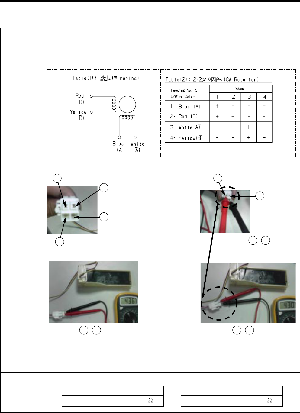
- 55 -
11-7 Damper
Function The damper supplies the cold air from the freezer to the refrigerator section.
How to
Measure
< Damper Circuit >
< extension >
Check the ,
Standard Damper
Test Points
Red and Yellow
Result
373 ~ 456
Test Points
Blue and White
Result
373 ~ 456
Check the resistance between connectors 1,3 and 2,4.
1Blue 1Blue
2Red
3White
3White
1 3
Check the ,
2 4 Check the ,
1 3
3Yellow
- 56 -
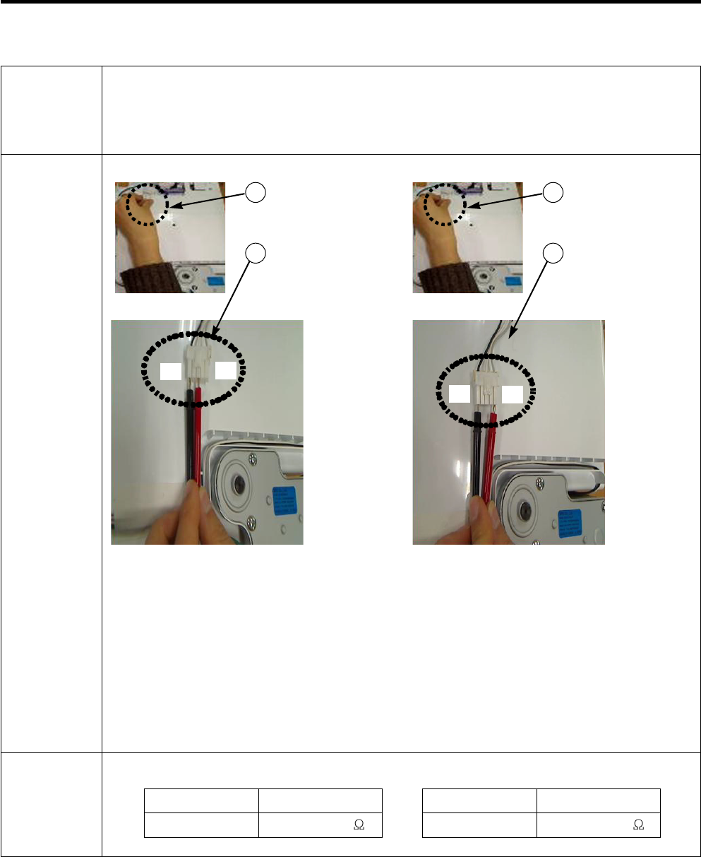
11-8 Light Bulb Socket
Function Make sure the light bulb is screwed in tight to the light socket.
How to
Measure
Standard
Check the resistance between connector of housing and connector of lamp socket.
Test Points
(1) to (2) and (3) to (4)
Result
0
(1) (2)
(3) (4)
- 57 -
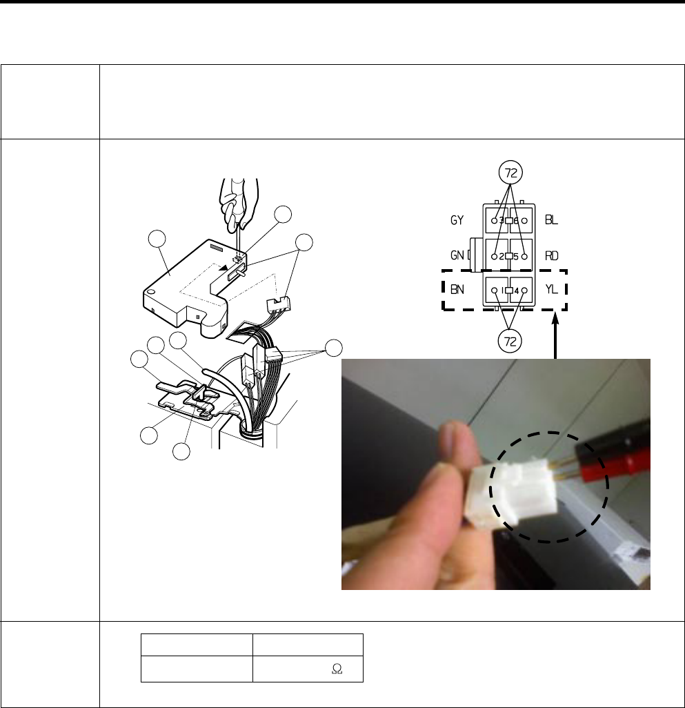
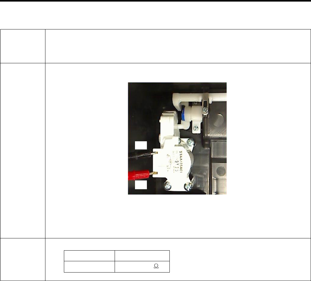
11-9 Flow Sensor
Function Flow Sensor (in machine room)
Count the water quantity from city water to water filter in refrigerator
How to
Measure
Standard
Flow Sensor
(in machine room)
Test Points
Red wire to Black wire
Result
4 ~ 30
- 58 -
12. TROUBLESHOOTING
Month
1: January O : October
N : November
9: September D : December
~
The information tag provides compressor model, refrigerant, serial number and safety approval
There are two types of controllers used in the linear compressor system.
-The “E”-inverter system is used with the FC75LANE compressor.
-The “A”-inverter system is used with the FC90LANA compressor.
Name Plate
Compressor Label
12-1 INFORMATION OF LINEAR COMPRESSOR
FC75LANE
Size : 90mm X 20mm
1. Compressor Model
2. Refrigerant
3. Serial Number
4. Safety Approval
Ex)
F C 7 5 L A N E
00 00 9 2003 5 13 0012
Series name
DLF/FA/FB
Operating Type
A:A-Inverter
E:E-Inverter
Rated Voltage
& Frequency
-M : 220V 50/60Hz
-N : 115V 50/60Hz
Efficiency version
A:1
st generation
B:2
nd generation
Displacement
ex)90=9.0 /stroke
Application Category
-L: LBP with R134a
-H: HBP with R134a
-N: LBP with R600a
Buyer Code
Model Code
Line
Serial No.
Date
Year
*VVVF : Variable Voltage Variable Frequency
**CVCF : Constant Voltage Constant Frequency
FC75LANE
E-Inverter
System
FC90LANA
A-Inverter
System
Refrigerator
Comp On/Off
Comp Drive
Inverter
CVCF
Compressor
Self
Modulation
Controls the
algorithm
according to
various
conditions
Inverter
VVVF
Stroke
Modulation
- 59 -
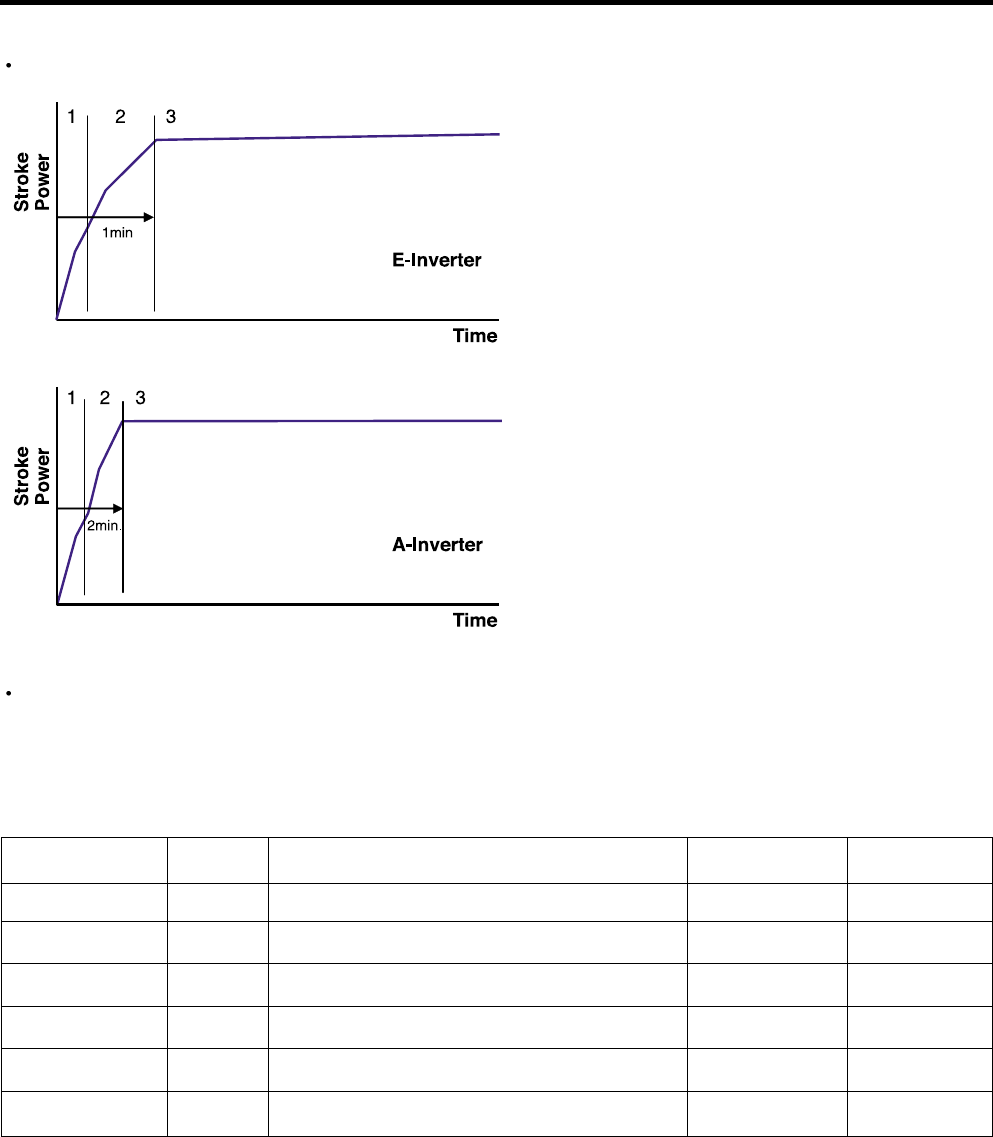
To reduce noise level, the piston stroke is slowly increased to full power during start up.
There are 6 protection logics designed to protect the linear compressor system. When a failure is detected,
the compressor will shut and will try to restart after a set period of time for each type of failure. The LED
located on the inverter drive PCB will flash the appropriate code to indicate the detected failure. This code will
continue to flash until the unit is disconnected from the power source.
Inverter Error Codes
Step 1) Start up - Half stroke interval for first 1 second.
Step 2) Ramp up - Stroke increases every 0.8sec until
maximum stroke length is reached
(about 1 min)
Step 3) CVCF interval - 180V / 60Hz
Step 1) Start up - Half stroke interval for first 20
seconds.
Step 2) Ramp up - Stroke increases until maximum
stroke length is reached (about 1 min, 40 sec)
Step 3) VVVF interval - target voltage and frequency
controlled by Control Board signals
FCT0
Stroke Trip
Locked Piston
Trip
Current Trip
IPM Fault
Communication
Error
App.
A-Inv.
E-Inv.
A-Inv.
E-Inv.
A-Inv.
E-Inv.
A-Inv.
E-Inv.
A-Inv.
A-Inv.
Requirement
Compressor current and voltage error.
Piston stroke overrun detected.
Piston is locked.
Current overload detected.
High current detected due to IPM failure.
Miscommunication with Refrigerator
1
2
5
6
7
8
The number of
LED flashes
Waiting Time
20 sec.
1 min.
2 min. 30 sec.
6 min.
20 sec.
0
- 60 -
Bridge Diodes converts 115V AC (Alternating current) to 115V DC (Direct current)
The Voltage Multiplying circuit then increases the 115V DC to 230V DC.
Then the IPM (Intelligent Power Module) converts the 230V DC to 230V AC.
The converted AC power can be regulated to any required voltage and frequency.
Measure the voltage at locations on the connector (as shown picture) with a multi-tester.
There is a PCB located in the PCB case next to the
compressor. That is the driver PCB, the linear
compressor.
E-Inverter
FC75LANE
A-Inverter
FC90LANA
Multi
Tester
Multi
Tester
E-Inverter
A-Inverter
IPM Voltage Check
To ensure proper diagnosis, make sure that the unit
has been plugged in for at least 10 min.
To determine if the compressor is receiving the
proper voltage, check the PCB output voltage
during operation.
Normal operating voltage will be between 80V AC
and 180V AC.
Note : Higher voltage readings may occur under
“heavy” load conditions.
- 61 -
Insulation check : Check for infinite Ohms between all compressor terminal and ground.
LG Linear Compressor
FC90LANA
Po N/C
Co
Capacitor Spec.
450V/18uF 5%
Po : Power
Co : Common
N/C : No Connecting
Compressor Winding Resistance Check
6 ~ 8
Ω
Between Po and Co
FC75LANE
Po N/C
Co
Capacitor Spec.
550V/10uF 5%
Po : Power
Co : Common
N/C : No Connecting
Compressor Winding Resistance Check
6 ~ 8
Ω
Between Po and Co
6 ~ 8
Ω
6 ~ 8
Ω
Inf (~)
Inf (~)
NOTE : Any Terminal to Ground should
read Inf ( ~ )

- 62 -
12-2 SERVICE DIAGNOSIS CHART
COMPLAINT POINTS TO BE CHECKED REMEDY
No Cooling. •Is the power cord unplugged from the outlet?
•Check if the power switch is set to OFF.
•Check if the fuse of the power switch is shorted.
•Measure the voltage of the power outlet.
•Plug into the outlet.
•Set the switch to ON.
•Replace the fuse.
•If the voltage is low, correct the wiring.
Cools poorly. •Check if the unit is placed too close to the wall.
•Check if the unit is placed too close to the stove,
gas cooker, or in direct sunlight.
•Is the ambient temperature too high or the room
door closed?
•Check if food put in the refrigerator is hot.
•Did you open the door of the unit too often or check
if the door is sealed properly?
•Check if the Control is set to Warm position.
•Place the unit about 4 inches (10 cm) from the wall.
•Place the unit away from these heat sources.
•Lower the ambient temperature.
•Put in foods after they have cooled down.
•Don't open the door too often and close it firmly.
•Set the control to Recommended position.
Food in the
Refrigerator is
frozen.
•Is food placed in the cooling air outlet?
•Check if the control is set to colder position.
•Is the ambient temperature below 41°F(5°C)?
•Place foods in the high-temperature section.
(front part)
•Set the control to Recommended position.
•Set the control to Warm position.
Condensation or ice
forms inside the unit.
•Is liquid food sealed?
•Check if food put in the refrigerator is hot.
•Did you open the door of the unit too often or check
if the door is sealed properly?
•Seal liquid foods with wrap.
•Put in foods after they have cooled down.
•Don't open the door too often and close it firmly.
Condensation forms
in the Exterior Case.
•Check if the ambient temperature and humidity of
the surrounding air are high.
•Is there a gap in the door gasket?
•Wipe moisture with a dry cloth. It will disappear in
low temperature and humidity.
•Fill up the gap.
There is abnormal
noise.
•Is the unit positioned in a firm and even place?
•Are any unnecessary objects placed in the back
side of the unit?
•Check if the Drip Tray is not firmly fixed.
•Check if the cover of the compressor enclosure in
the lower front side is taken out.
•Adjust the Leveling Screw, and position the
refrigerator in a firm place.
•Remove the objects.
•Fix the Drip Tray firmly in the original position.
•Place the cover in its original position.
Door does not
close well.
•Check if the door gasket is dirty with an item like
juice.
•Is the refrigerator level?
•Is there too much food in the refrigerator?
•Clean the door gasket.
•Position in a firm place and level the Leveling
Screw.
•Make sure food stored in shelves does not prevent
the door from closing.
Ice and foods
smell unpleasant.
•Check if the inside of the unit is dirty.
•Are foods with a strong odor unwrapped?
•The unit smells of plastic.
•Clean the inside of the unit.
•Wrap foods that have a strong odor.
•New products smell of plastic, but this will go away
after 1-2 weeks.
Other possible problems:
Check if frost forms in
the freezer.
Check the
refrigeration system.
Check the Thermistor.
Not defrosting
The system
is faulty.
The operation of
the Thermistor is
incorrect.
Check Components of the
defrosting circuit.
Perform sealed
system repair.
Replace the Thermistor.

- 63 -
12-3 REFRIGERATION CYCLE
Troubleshooting Chart
PARTIAL
LEAKAGE
Freezer
compartment and
Refrigerator don't
cool normally.
Low flowing sound of
Refrigerant is heard
and frost forms in
inlet only.
A little higher than
ambient
temperature.
•Refrigerant level is low due
to a leak.
•Normal cooling is possible by
restoring the normal amount
of refrigerant and repairing
the leak.
COMPLETE
LEAKAGE
Freezer
compartment and
Refrigerator don't
cool normally.
Flowing sound of
refrigerant is not
heard and frost isn't
formed.
Equal to ambient
temperature.
•No discharging of
Refrigerant.
•Normal cooling is possible by
restoring the normal amount
of refrigerant and repairing
the leak.
LEAKAGE
PARTIAL
CLOG
Freezer
compartment and
Refrigerator don't
cool normally.
Flowing sound of
refrigerant is heard
and frost forms in
inlet only.
A little higher than
ambient
temperature.
•Normal discharging of the
refrigerant.
•The capillary tube is faulty.
WHOLE
CLOG
Freezer
compartment and
Refrigerator don't
cool.
Flowing sound of
refrigerant is not
heard and frost isn't
formed.
Equal to ambient
temperature.
•Normal discharging of the
Refrigerant.
MOISTURE CLOG Cooling operation
stops periodically.
Flowing sound of
refrigerant is not
heard and frost melts.
Lower than ambient
temperature.
•Cooling operation restarts
when heating the inlet of the
capillary tube.
CLOGGED BY DUST
COMP-
RESSION
Freezer and
Refrigerator don't
cool.
Low flowing sound of
refrigerant is heard
and frost forms in
inlet only.
A little higher than
ambient
temperature.
•Low pressure at high side of
compressor due to low
refrigerant level.
NO COMP-
RESSION
No compressing
operation.
Flowing sound of
refrigerant is not
heard and there is
no frost.
Equal to ambient
temperature.
•No pressure in the high
pressure part of the
compressor.
DEFECTIVE
COMPRESSION
CAUSE REMARKS
STATE OF THE
EVAPORATOR
TEMPERATURE
OF THE
COMPRESSOR
STATE OF
THE UNIT
- 64 -
12-3-1 SEALED SYSTEM DIAGNOSIS
“Not Cooling” Complaint
All components operating, No airflow problems, Not frosted up as a defrost problem
problem has been isolated to sealed system area
Frost
Pattern?
Partial
Equalization
Test
Very Slow
None
Equalization
Test
Very Fast
Fast
Very Fast
Inefficient
Compressor
Partial
Restriction
Complete
Restriction
Condenser
Temperature
Cap Tube
Sound
Yes
No
Air/Low Side
Leak
Loss of Change
Very Slow
Faint
Hotter than Normal
None to Weak
Room Temperature
Compressor Not
Pumping
Trace of Oil
Undercharge
(The equalization test is trying to restart a compressor using a start kit after it has been operating.)
Leak
- 65 -
13. OPERATION PRINCIPLE AND REPAIR METHOD OF ICEMAKER
13-1 OPERATION PRINCIPLE
13-1-1 Operation Principle of IceMaker
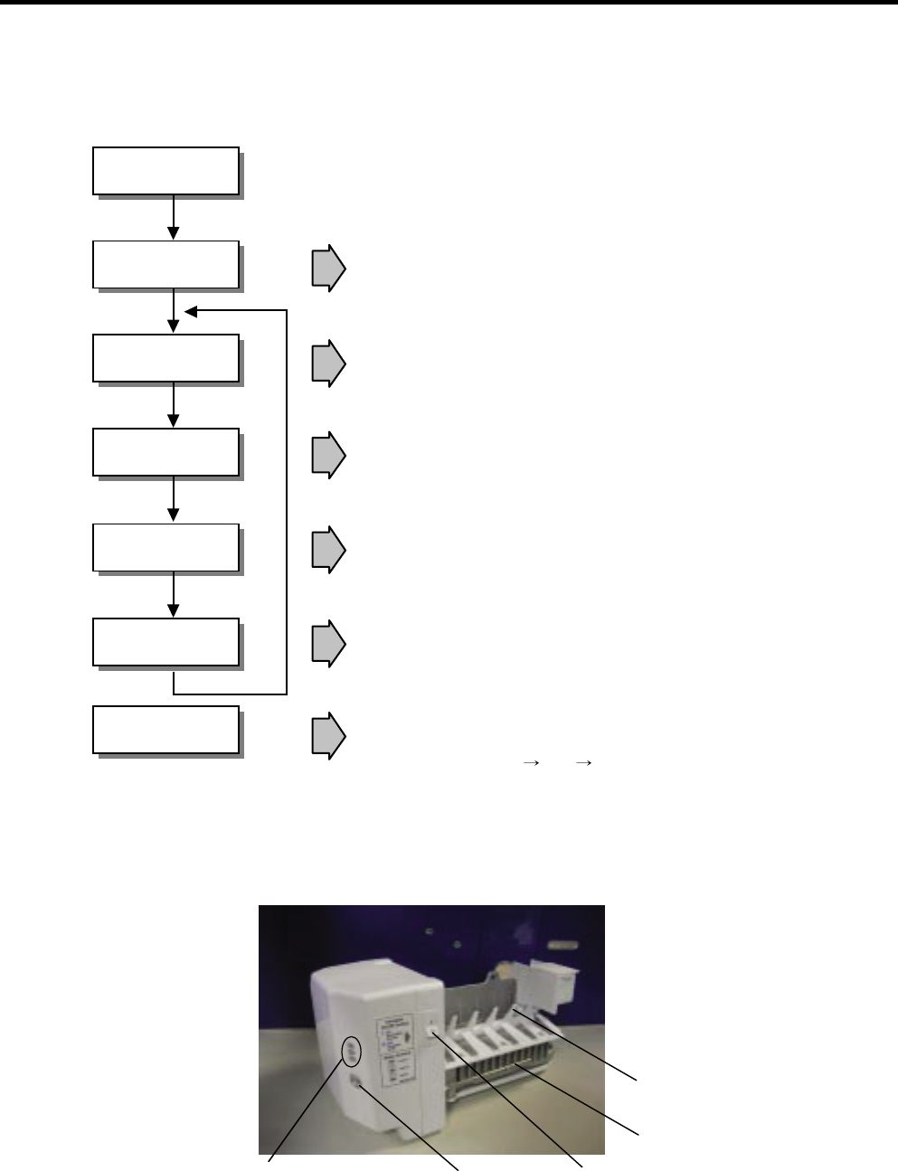
Power On
Start Position •Adjusts EJECTOR to Start Position with power on.
Icemaking
Mode •Waits until water becomes ICE after starting the
icemaking operation.
Harvest
Mode
•Runs MOTOR to drop ice from the tray into the ICE BIN.
(During harvest mode, check if the ice bin is full)
Park Position •Reaches Start Position
Fill •Performs Ice Making Mode after supplying water by
operating the SOLENOID in ICE VALVE.
Test Mode •To operate LINE and SERVICE, press and hold the
Fill Key for 3 seconds. The icemaker will run through
3 stages: Harvest Fill Icemaking.
1. Turning the Icemaker stop switch off (O) stops the ice making function.
2. Setting the Icemaker switch to OFF and then turning it back on will reset the icemaker control.
Cube Size
Indicator Light Cube Size
Selection Button
Automatic
Shut off Arm
Power
Switch
EJECTOR
- 66 -
13-2 ICE MAKER FUNCTIONS
13-2-1 Icemaking Mode
1. Icemaking refers to the freezing of supplied water in the ice tray. Complete freezing is assured by measuring the
temperature of the Tray with Icemaking SENSOR.
2. Icemaking starts after completion of the water fill operation.
3. The Ice Making function is completed when the sensor reaches 19°F (-7°C), 55 minutes after starting.
NOTE : After Icemaker Power is ON, the Icemaker heater will be on for test for 6 sec.
13-2-2 Harvest Mode
1. Harvest (Ice removing) refers to the operation of dropping ices into the ice bin from the tray when icemaking has
completed.
2. Harvest mode:
(1)The Heater is ON for 30 seconds, then the motor starts.
(2)The feeler arm senses the quantity of ice in the ice storage bin while rotating with the EJECTOR.
A. Ice storage bin is full : The EJECTOR stops (heater off).
B. Ice storage bin is not full : The EJECTOR rotates twice to open for ice.
If the EJECTOR does not rotate once within 5 minutes in B mode, separate heater control mode starts operating to
prevent the EJECTOR from being constrained. (It is recommended that the user open for ice to return to normal mode.)
13-2-3 Fill/Park Position
1. Once a normal harvest mode has been completed, the water solenoid will be activated.
2. The amount of water is adjusted by pressing the Fill Key repeatedly. This changes the time allowed for fill as illustrated in
the table below.
STAGE TIME TO SUPPLY INDICATIONS REMARKS
15 sec.
The water amount will vary
depending on the water control
Switch setting, as well as the
water pressure of the connected
water line.
Water supply amount TABLE
25.5 sec.
(FIRST STAGE)
36 sec.
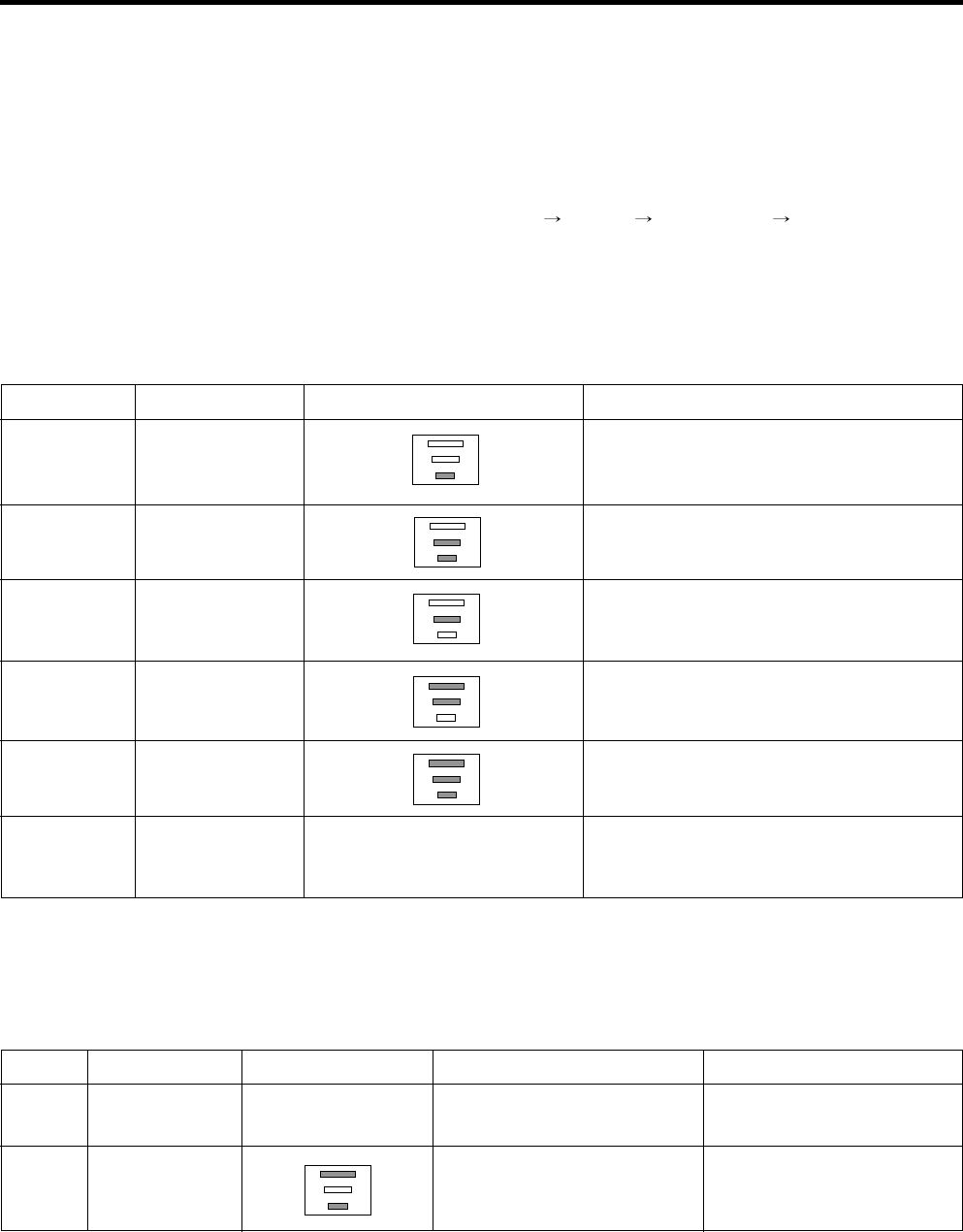
- 67 -
STAGE ITEMS INDICATOR REMARKS
1 HEATER
Five seconds after heater starts, a heater
will go off if the temperature by sensor is
higher than 10°C
Diagnosis TABLE
2MOTOR Five seconds after heater starts, you can
confirm that a motor is moving.
3HALL IC I Check if Ice Bin is full or not.
If Ice bin is full, the motor and heater are
off and on stand by until Ice bin is empty.
4HALL IC II You can confirm HALL IC detection of
start position.
5 VALVE Two seconds after detection of start
position, you can confirm that valve is on.
6 Reset
Five seconds after fifth stage is
completed, The icemaker resets to initial
status.
Return to Status prior to
TEST MODE
NO DIVISION INDICATOR REMARKS
1Normal Display switch operates
properly
Mark time to supply
2
Icemaking
Sensor
malfunction
Make sure that the wire on
each sensor is connected.
CONTENTS
None
Open or short-circuited wire
13-3 DEFECT DIAGNOSIS FUNCTION
13-3-1 ERROR CODES shown on Ice Maker water supply control panel
13-2-5 Function TEST
1. This is a forced operation for TEST, Service, cleaning, etc. It is operated by pressing and holding the Fill Key for
3seconds.
2. The test works only in the Icemaking Mode. It cannot be entered from the Harvest or Fill mode.
3. Caution! If the test is performed before water in the icemaker is frozen, the ejector will pass through the water. When the
Fill mode begins (Stage 4), unless the water supply has been shut off, added water will overflow into the ice bin. If the
control doesn’t operate normally in the TEST mode, check and repair as needed.
4. After water is supplied, the normal CYCLE is followed : icemaking Harvest Park Position Fill.
5. Five seconds after Stage 5 is completed, the Ice Maker returns to MICOM control. The time needed to supply water
resets to the pre- test setting.
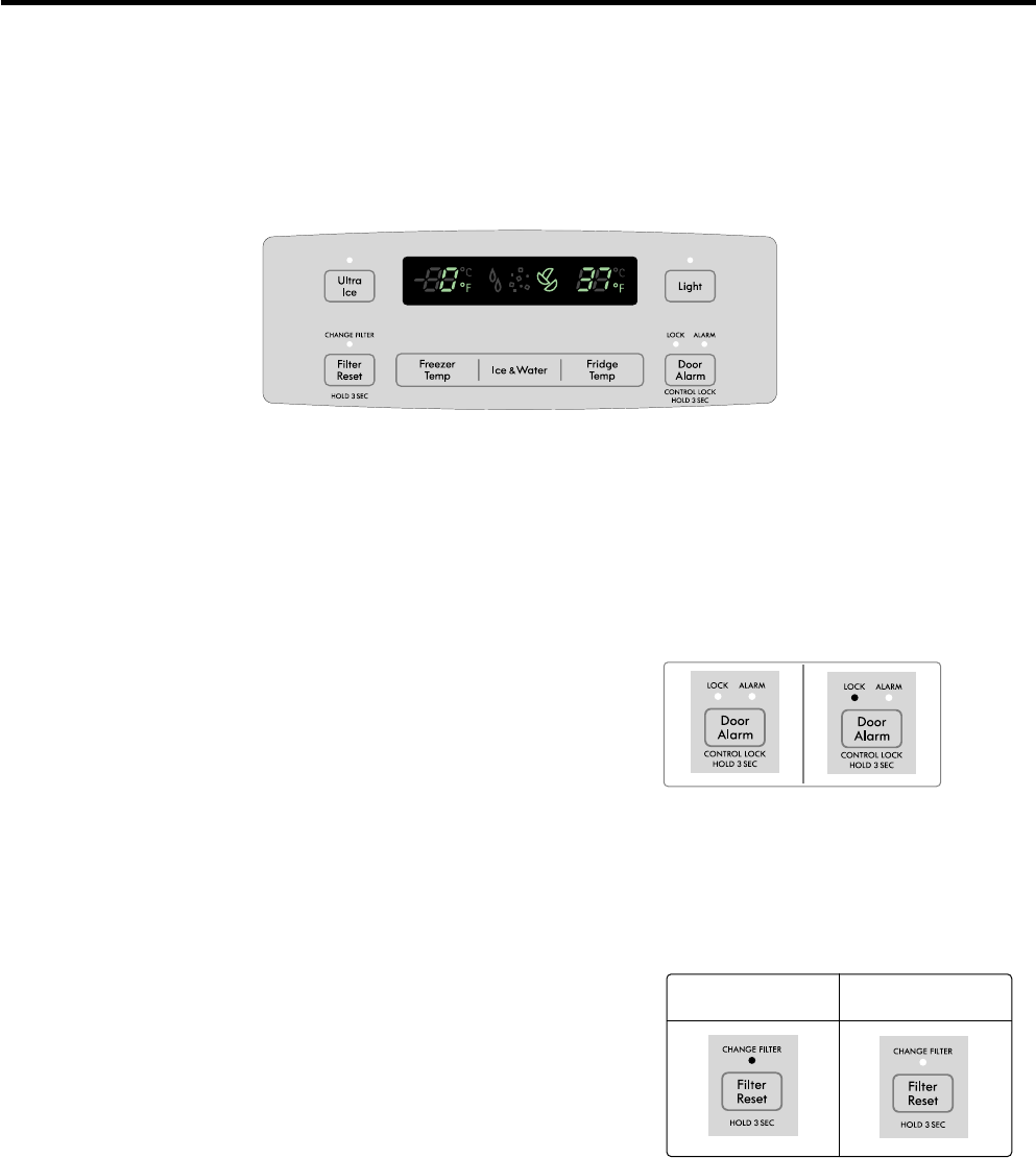
- 68 -
14. DESCRIPTION OF FUNCTION & CIRCUIT OF MICOM
14-1 FUNCTION
14-1-1 Function
1. When the appliance is plugged in, it is set to 37°F for Refrigerator and 0°F for freezer.
You can adjust the Refrigerator and the Freezer control temperature by pressing the ADJUST button.
2. When the power is initially applied or restored after a power failure, it is set to Control temperature Previously.
14-1-2 How to Toggle the Display between °F & °C
1. The initial setting is °F and the display temperature mode can be changed from °F to °C or °C to °F by pressing and
holding the Freezer Temp and the Fridge Temp keys at the same time for over 5 seconds.
14-1-4 Filter condition display function
1. There is a replacement indicator light for the filter
cartridge on the dispenser.
2. Water filter needs replacement once six months or of
using water filter.
3. Water Filter icon turn on to tell you need to replace the
filter soon.
4. After replacing the filter, press and hold the lock button
more than 3 seconds.
Water Filter icon turn off with reset status.
14-1-3 Lock function (dispenser and display button lock)
1. When the refrigerator is first turned on, the buttons are not locked.
The display panel shows the padlock unlocked icon.
2. To lock the display, the dispenser, and the control panel, press and
hold the LOCK button for 3 seconds. The locked pad lock icon is
displayed.
3. The LOCK button is the only control feature that remains active in the
locked state. The buzzer sound, other control buttons, and the
dispenser are deactivated.
4. To release from the locked state, press and hold the LOCK button
again for 3 seconds.
In initial Power On
/ Filter RESET
Replace indicator
light on
Filter Status
Display
Classification
Ex) In selecting
“LOCK”
Ex) In selecting
“LOCK” again
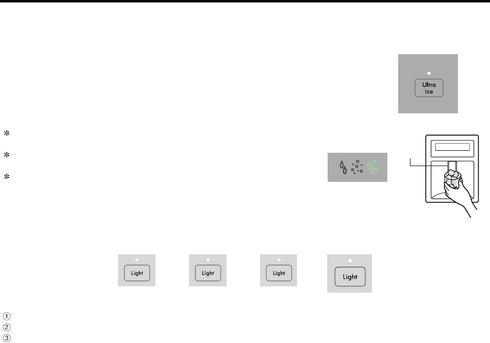
- 69 -
14-1-5 Ultra Ice selection
Please select this function for quick freezing.
•Function is repeat Ultra Ice Icon whenever pressing Ultra Ice button.
•Ultra Ice function automatically turns off after a fixed time passes.
14-1-7 DISPENSER LIGHT
-Whenever pressed the LIGHT button, DISPLAY is changed as belows.
14-1-8 CONTROL OF FREEZER FAN MOTOR
1. Freezer fan motor has high and standard speeds.
2. High speed is used at power-up, for Ultra Ice, and when refrigerator is overloaded.
Standard speeds is used for general purposes.
3. To improve cooling speed, the RPM of the freezer fan motor change from normal speed to high.
4. High speed (2700RPM) : Initial power on or load corresponding operation, Ultra Ice.
Normal speed (2400RPM) : General working conditions.
5. Fan motor stops when refrigerator or freezer door opens.
14-1-9 Cooling Fan Motor
1. The cooling fan is switched ON and OFF in conjunction with the compressor.
2. The cooling fan Motor has high and standard speeds. (When room temper rapture more high then 38°C speed is high)
3. The Failure sensing method is the same as in the fan motor of the freezing fan motor(refer to failure diagnosis function
table for failure display).
14-1-10 Ice Compartment Fan
1. The Icing Fan is controlled by the the sensor on the top of the ice compartment.
2. The Failure sensing method is the same as in the fan motor of the freezer
(refer to failure diagnosis function table for failure display)
Normal status : When dispenser is operated, DISPENSER LIGHT is ON.
AUTO status : Detecting the lighting of room by LIGHT SENSOR, DISPENSER LIGHT is on and off automatically.
ON status : DISPENSER LIGHT is on continuously.
14-1-6 Dispenser use selection
You can select water or ice.
Select water, crushed ice, or ice cubes by cycling through the selections
when pressing the DISPENSER button,
Hold your cup in the dispenser for a few seconds after dispensing ice or
water to allow the last pieoes of ice or drops of water to fall into the cup.
When after initially establ ishing the water comes out, the water tank inside
fills and until at the time of quality the hour is caught.
Pressing
Switch
① ②
Auto
③
On
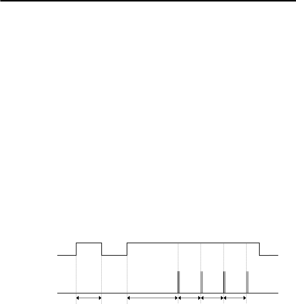
- 70 -
14-1-11 Ultra Ice
1. The purpose of this function is to intensify the cooling speed of freezer and to increase the amount of ice.
2. Whenever selection switch is pressed, selection/release, the LCD will turn ON or OFF.
3. If there is a power outage and the refrigerator is powered on again, Ultra Ice will be canceled.
4. To activate this function, press the Ultra Ice key and the LCD will turn ON. This function will remain activated for 24 hrs.
The first three hours the compressor and Freezer Fan will be ON. The next 21 hours the freezer will be controlled at the
lowest temperature. After 24 hours or if the Ultra Ice key is pressed again, the freezer will return to its previous
temperature.
5. During the first 3 hours:
(1) Compressor and freezer fan (HIGH RPM) run continuously.
(2) If a defrost cycle begins during the first 90 minutes of Ultra Ice , the Ultra Ice cycle will complete its cycle after
defrosting has ended.
If the defrost cycle begins when Ultra Ice has run for more than 90 minutes, Ultra Ice will run for two hours after the
defrost is completed.
(3) If Ultra Ice is pressed during defrost, Ultra Ice LCD is on but this function will start seven minutes after defrost is
completed and it shall operate for three hours.
(4) If Ultra Ice is selected within seven minutes after compressor has stopped, the compressor (compressor delays seven
minutes) shall start after the balance of the delay time.
(5) The fan motor in the freezer compartment runs at high speed during Ultra Ice.
6. For the rest of the 21 hours, the freezer will be controlled at the lowest temperature.
14-1-12 Alarm for Open Door
1. This feature sounds a buzzer when the freezer or refrigerator door is not closed within 1 minute after it is opened.
2. One minute after the door is opened, the buzzer sounds three times each for 1/2 seconds. These tones repeat every
30seconds.
3. The alarm is cancelled when the freezer or the refrigerator is closed while the buzzer sounds.
Freezer Door
or Refrigerator
Door
Closed Open Closed ClosedOpen
3 Times 3 Times 3 Times 3 Times
Within 1 min. 1 min. 30 sec 30 sec 30 sec
Buzzer
14-1-13 How to set the display mode and cancel It
1. With the refrigerator door open, keep pressing the Refrigerator Temp Button and ULTRA ICE Button more than 5
seconds, then it goes to the display mode with Special Beep Sound.
2. Perform the same way agin to cancel the display mode.
3. All freezing units do not work at the display mode. (Exceptions : Display, Lamp)
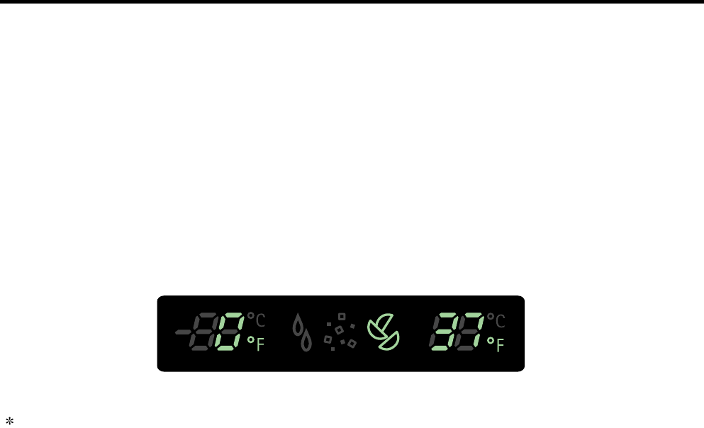
- 71 -
14-1-14 Defrosting (removing frost)
1. Defrosting starts each time the COMPRESSOR running time Betwee 7~50 hours.
2. For initial power on or for restoring power, defrosting starts when the compressor running time reaches 4 hours.
3. Defrosting stops if the sensor temperature reaches 46.4°F(8°C) or more. If the sensor doesn’t reach 46.4°F(8°C) in
1hours, the defrost mode is malfunctioning. (Refer to the defect diagnosis function, 8-1-15.)
4. Defrosting won’t function if its sensor is defective (wires are cut or short circuited)
14-1-15 Defect Diagnosis Function
1. Automatic diagnosis makes servicing the refrigerator easy.
2. When a defect occurs, the buttons will not operate; but the tones. such as ding. will sound.
3. When the defect CODE removes the sign, it returns to normal operation (RESET).
4. The defect CODE shows on the Refrigerator and Freezer Display.
LED check function: If simultaneously pressing Ultra Ice button and freezing temperature adjustment button for a second,
display LED graphics on. If releasing the button, the LED graphic displays the previous status.
- 1 -
623B
616G
616J
603C
616D
627B
627A
619A
603B
619E
616F
616D
625A
616G
623B
616J
617A
S31
S32

- 2 -
S02
S01 103A
S01
103B
207A
S03
B01
207C
402A
406D
207B
S03
271B
402A
603B 603C
626A
624D
607A
624C
624A
282F
120A
120B
282G
145A
S08
610D
501F
500A
411A
313A
271D S10
610A
145B
S12
S12
105A
318A
316A
314A 300A
317A
310B
312A
304A
262H
250F
406B
B02
S14
249D
249C
B02
S14
262B
302B
400A
316B
408A
329A
S16 407A
332C
610C
S17
103C
315A
315C
315B
405B
405C
404A
405F
407B
106A
106A
315B
315C
B01
S14
158A
503D
409D
503E
409B
158B
312C
323B
329C
309B
420A
319C
319A
S20
290A
500H
410G
504A
413A
303A
CASE PARTS
CAUTION : Use the part number to order part, not the position number.
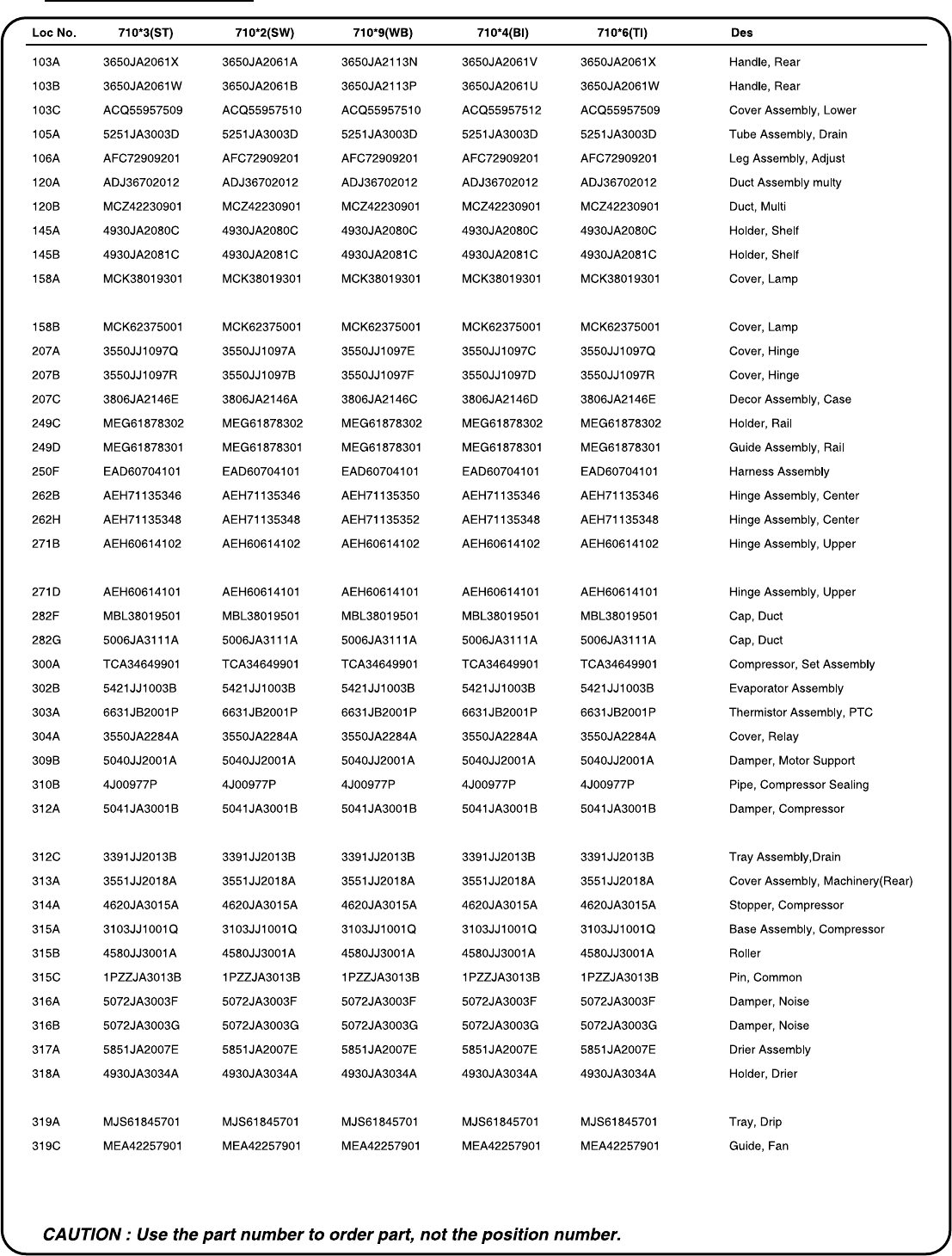
- 3 -
CASE PARTS
- 4 -
CASE PARTS
- 5 -
FREEZER PARTS
CAUTION : Use the part number to order part, not the position number.
145F
145C
145G
145J
145K
145M
145J
145H
136A
237C
136B
237D
131A
CAUTION : Use the part number to order part, not the position number.
- 6 -
REFRIGERATOR PARTS
141A
141B
141C
141A
141B
141C
154A
151B
161A
162A
145D
162B
146E
151A
161B
161C
141D
141C
141B 141A
141A
141B
141C
- 7 -
DOOR PARTS
CAUTION : Use the part number to order part, not the position number.
230B
233B231B
234D
233C
234B
B05
241A
241B
241G
B05
243C
243A
243B
S25
615A
244A
619B
603B
603C
603C
616H
312B
203A
212D
B06
B06
250B
250B
249H
249K
250A
200A
249G
249E
249J
201A
249F
250H
230A
233A 231A
234C
233D
234A
212G
B05
244A 243B
S25
243A
262C
243C
B05
262C
241D
241D
241F
241C
241H
241J
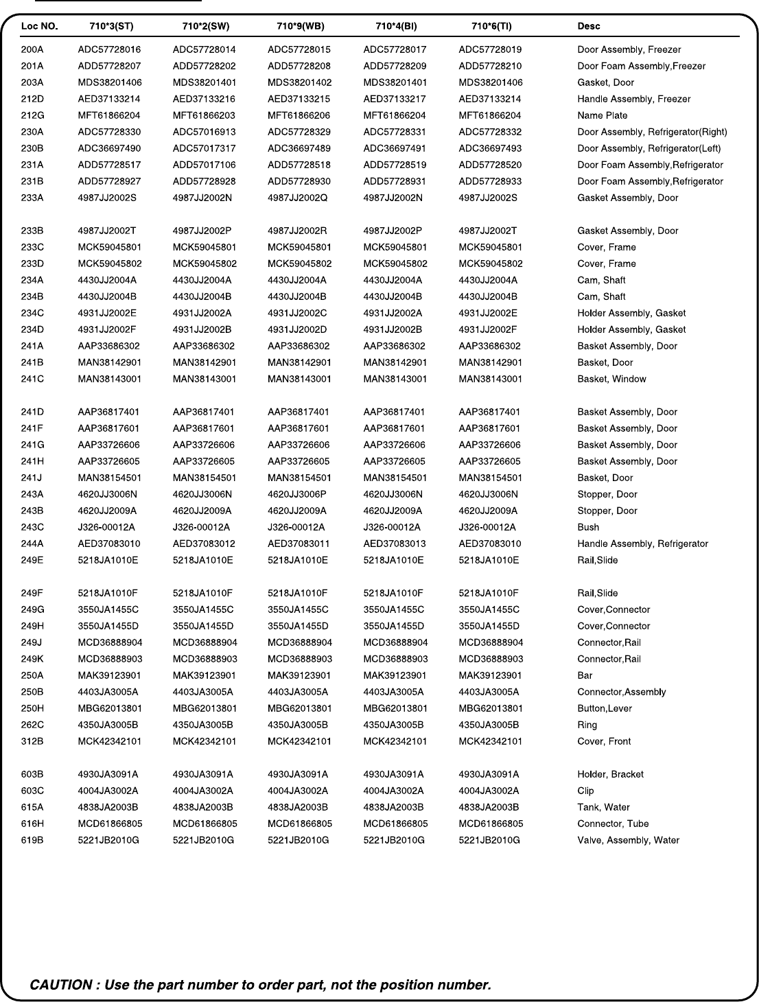
- 8 -
DOOR PARTS
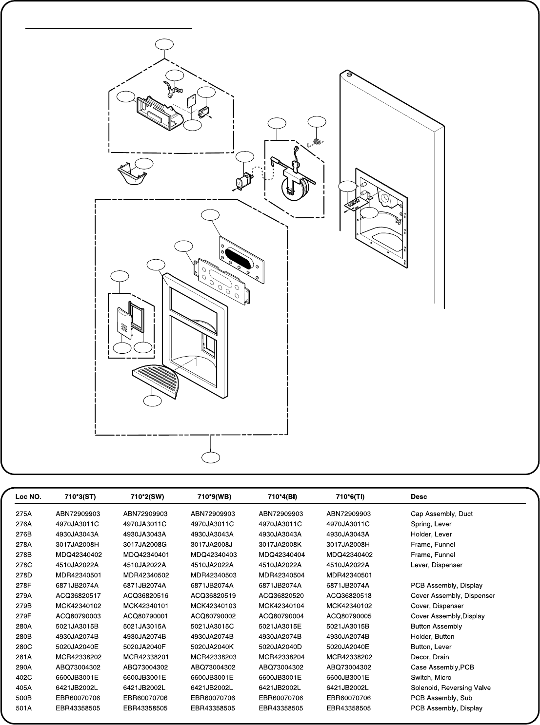
- 9 -
DISPENSER PARTS
278A
278C
402C
278F
278B
278D
405A
275A 276A
500B
276B
501A
279F
279B
281A
279A
280A
280C
280B
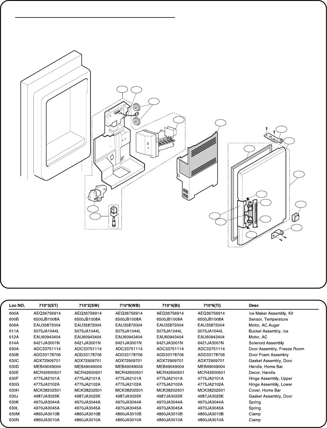
- 10 -
ICE MAKER & ICE BANK PARTS
612A 600B
630J
600A
611A
606A
614A 630E
630D
630K
630M
630N
630L
630G
630H
630A
630C
630B
630F