Kentrox Ai296 Users Manual Version 9.8x User's Guide
AI296 to the manual 30c16133-3791-43fe-9fca-a127393f87b6
2015-02-09
: Kentrox Kentrox-Ai296-Users-Manual-568093 kentrox-ai296-users-manual-568093 kentrox pdf
Open the PDF directly: View PDF ![]() .
.
Page Count: 404 [warning: Documents this large are best viewed by clicking the View PDF Link!]
- Product Description
- Features
- Break Propagation
- BX.25 Compatibility
- DCD/DSR/RTS/DTR Signal Lead Control
- Dynamic Port Configuration
- EIA Lead Signaling
- IRB Connectivity
- Line Monitoring Diagnostics
- Link-to-Link Call Routing
- Performance Monitoring, Maintenance, Troubleshooting
- Remote and Local Configuration
- Simultaneous Connections
- Single Alias Translation
- SNMP Manageability
- Standalone Configuration
- System Diagnostics
- TID Multiplexing
- AI296 Hardware Components
- Technical Specifications
- Individual Port Access
- Typical Applications
- Features
- Using the AI198TM Menu System
- AI296 Local Menu System
- System Configuration
- IP Over X.25 Subnet Configuration
- Link Configuration
- AI296 Link Types
- BX.25 Configuration
- Connect Options Configuration
- Disconnect Options Configuration
- General Link Properties Configuration
- General PPP Properties Configuration
- LAPB Parameters Configuration
- Modem Option Configuration
- PPP Authentication Configuration
- Quick X.25 Configuration
- RTS/DTR Lead Control Configuration
- X.25 Parameters Configuration
- Virtual Circuit Configuration
- TID Multiplexing
- Alias and Call Routing Configuration
- AI296 Commands
- Commands Overview
- winslc Commands
- aaa
- alarm
- arp
- break
- bridge
- creset
- date
- debug
- delete
- diag-conn
- diag-eth
- diag-info
- diag-line
- diag-tconn
- dir
- exit
- head
- help
- id
- ip
- ip init
- link
- linkstat
- log
- logout
- ls
- menu
- more
- pad
- panic
- passwd
- ping
- pppstatus
- profile
- pvcedit
- pvclist
- reset
- rz
- selcnf
- sholog
- show
- staeia
- standalone
- staslc
- syncflash
- sz
- tacacs
- tacacs server
- tail
- tcpoutconn
- tftp
- tftpboot
- timezone
- trace
- traceroute
- type
- update
- uptime
- useradd
- userdel
- users
- who
- xvc
- AI296 System Codes
- Standalone Mode and Switch Mode
- Commands for AI296 TACACS+ Server Enhancements
© 2008 by Kentrox, Inc. All rights reserved.
AI296TM
16-Port High Speed Multi-Protocol Line Card
User’s Guide
Version 9.8x
Part Number 296UM Rev 5

Copyright © 2008 by Kentrox, Inc. All Rights Reserved. The material discussed in this publication
is the proprietary property of Kentrox, Inc. Kentrox retains all rights to reproduction and
distribution of this publication.
Kentrox is a registered trademark of Kentrox, Inc. Applied Innovation, Applied Innovation Inc., the
AI logo, and other names are the intellectual property of Kentrox. All other product names are
trademarks or registered trademarks of their respective owners.
Information published here is current as of this document’s date of publication, but is subject to
change without notice. You may verify product information by contacting our headquarters in
Oregon. Kentrox is an Equal Opportunity/Affirmative Action employer.
Kentrox, Inc.
5800 Innovation Dr.
Dublin, Ohio USA 43016-3271
Toll Free: (800) 247-9482
International: +1 (614) 798-2000
Fax: +1 (614) 798-1770
15201 NW Greenbrier Pkwy.
Suite C6
Beaverton, Oregon USA 97006
Toll Free: (800) 733-5511
Direct: (503) 643-1681

i
About this Document
This document explains how to install, configure, and operate the AI296 16-port high speed
multi-protocol line card.
You should have a working knowledge of the following:
zYour network
zAISwitchTM technology
zX.25 protocol
zAsynchronous protocols
zTCP/IP
zPC or asynchronous terminal configuration

AI296 Version 9.8x User’s Guide
About this Document: Document Conventions
ii
Document Conventions
Table 1 describes the text conventions used in this document.
Table 1 Document Conventions
Convention Meaning
Screen Text, Menu Items,
System Prompts, Messages
and Reports
This style indicates Kentrox configuration screen text,
menu items, system prompts, messages, and reports.
Static Command Text In a command statement, this style indicates text that
should be entered exactly as shown at a command line.
Variable Command Text
In a command statement, this style indicates
user-specified text.
... In a command statement, ellipses (...) signify that the
preceding parameter can be repeated a number of
times.
[ ]
[ | ] In a command statement, square brackets indicate an
optional parameter. Two or more parameters in square
brackets with a vertical bar ( | ) between them indicate a
choice of optional parameters.
{ | } In a command statement, two or more parameters in
braces with a vertical bar ( | ) between them indicate a
choice of required parameters.
Variable Field Text This style indicates variable information you type in a
dialog box field.
KEYS Uppercase body text indicates keys on a keyboard,
such as the TAB or ENTER keys. Keys used in
combination are connected with a plus symbol (+).
Labels This style designates physical components on Kentrox
products such as jumpers, switches, and cable
connectors.
Note:
Note messages emphasize or supplement important
points of the main text.
Important: Important messages provide information that is
essential to the completion of a task.
Tip:
Tip messages provide information that assists users in
operating equipment more effectively.

AI296 Version 9.8x User’s Guide
About this Document: Document Conventions
iii
CAUTION:
Caution messages indicate that failure to take a
specified action could result in loss of data and/or harm
to the software or hardware.
WARNING:
Warning messages indicate that failure to take a
specified action could result in physical harm to the
user.
Table 1 Document Conventions (Continued)
Convention Meaning

AI296 Version 9.8x User’s Guide
About this Document: Cautions and Warnings
iv
Cautions and Warnings
Electrostatic Discharge Caution
CAUTION: Kentrox equipment and its peripherals contain electrostatic sensitive
components. Proper handling, shipping, and storage precautions must
be exercised:
zYou must remove and install cards in a static-free environment. Wear
an antistatic wrist strap that is plugged into the Kentrox equipment so
you are grounded at the same point as the equipment.
zDo not remove cards from their antistatic plastic bags until you are
ready to install them into the chassis.
zImmediately after you remove a card from the chassis, you must
insert it into its antistatic bag.
zWhen the cards are not in use, keep them in their antistatic plastic
bags.
zDo not ship or store cards near strong electrostatic, electromagnetic,
or radioactive fields.
Ground Caution
CAUTION: For Kentrox equipment to operate safely and correctly, there must be a
safety ground strap between the equipment ground bolts and the office
ground.
Proper Cooling Caution
ENSURE PROPER COOLING
CAUTION: When AI296 is installed into an AI180TM AIswitch series 180 chassis, the
chassis must be equipped with the AIcoolTM chassis cooling and Baffle-
HS heat baffle with sensor assemblies.
The AI180I AIswitch series 180 integrated chassis has a built-in fan and
baffle assembly and does not require additional assemblies.

AI296 Version 9.8x User’s Guide
About this Document: Cautions and Warnings
v
FCC Warning
The Federal Communications Commission has set limits for emitted radio
interference, and AI296 is constructed with this electromagnetic interference (EMI)
limitation in mind. AI296 is classified under FCC regulations as a Class A device, that
is, a device for use in commercial environments and not in residential areas. This
device has been tested and shown to comply with the following FCC rule: Part 15
Subpart J. Operation of this equipment in a residential area may cause interference to
radio and TV reception, requiring the user to take whatever steps are necessary to
correct the interference.
Information is available from the FCC describing possible corrective actions. To
maintain low EMI levels, we suggest that you use only metal connectors and shielded
cable grounded to the frame.
Specifications are subject to change without notice.

AI296 Version 9.8x User’s Guide
About this Document: Customer Assistance
vi
Customer Assistance
Kentrox offers technical support 24 hours a day, seven days a week.
Before you contact Kentrox for assistance, please have the following information
available:
zThe type of hardware and software you are using
zThe error number and exact wording of any messages that appeared on your
screen
zWhat happened and what you were doing when the problem occurred
zHow you tried to solve the problem
Web Site Support
Support is available 24 hours a day using our Web site at:
http://www.kentrox.com
Email Support
Email support is available 24 hours a day. When you use email support, please be
sure to include the details of your problem within the email.
To contact Technical Support, send email to:
techsupport@aiinet.com
Phone Support
Phone support is available. When you call Kentrox for support, please be sure you
are at your computer and have the details of your problem available.
To contact Technical Support, call (866) 480-3571.
Kentrox Product Documentation
To order documentation, please contact your sales representative at
(800) 247-9482 or +1 (614) 798-2000.
You can also access and view the most current versions of Kentrox product
documentation on our Web site at:
http://www.kentrox.com

TOC-1
Table of Contents
Chapter 1: Product Description ..............................................................1-1
Features .......................................................................................................................1-2
Break Propagation ............................................................................................ 1-2
BX.25 Compatibility .......................................................................................... 1-2
DCD/DSR/RTS/DTR Signal Lead Control ........................................................ 1-2
Dynamic Port Configuration ............................................................................. 1-2
EIA Lead Signaling ........................................................................................... 1-2
IRB Connectivity ............................................................................................... 1-2
Line Monitoring Diagnostics ............................................................................. 1-2
Link-to-Link Call Routing .................................................................................. 1-3
Performance Monitoring, Maintenance, Troubleshooting ................................. 1-3
Remote and Local Configuration ...................................................................... 1-3
Simultaneous Connections ............................................................................... 1-3
Single Alias Translation .................................................................................... 1-3
SNMP Manageability ........................................................................................ 1-3
Standalone Configuration ................................................................................. 1-3
System Diagnostics .......................................................................................... 1-4
TID Multiplexing ................................................................................................ 1-4
AI296 Hardware Components ...................................................................................... 1-5
Front Panel Components ................................................................................. 1-6
Technical Specifications ............................................................................................... 1-7
Individual Port Access .................................................................................................. 1-8
CAB257 Cable .................................................................................................. 1-8
DP196 Distribution Panel ................................................................................. 1-8
Typical Applications ................................................................................................... 1-11
Asynchronous to TCP/IP Application ............................................................. 1-11
IP Over X.25 Networks ................................................................................... 1-12
Mixed Asynchronous and X.25 Networks ....................................................... 1-14
X.25 to TCP/IP Application ............................................................................. 1-16
X.25 Trunking ................................................................................................. 1-17
Chapter 2: Using the AI198TM Menu System ........................................2-1
Accessing the Menu System ........................................................................................ 2-2
Navigating the Menu System ....................................................................................... 2-3
Menu Numbering Structure .............................................................................. 2-3
Types of Menu Items ........................................................................................ 2-3

TOC-2
Table of Contents
Exiting the Menu System ............................................................................................. 2-6
Chapter 3: AI296 Local Menu System ....................................................3-1
Identifying AI296 Menu System Security Options ........................................................ 3-2
Multilevel User Name and Password Security ................................................. 3-2
RADIUS Authentication .................................................................................... 3-2
TACACS+ Authentication .................................................................................3-2
PPP Authentication Protocols (PAP and CHAP) .............................................. 3-2
Logging Into AI296 ....................................................................................................... 3-3
Using a Telnet Connection for Login ................................................................ 3-3
Using an Asynchronous Port for Login ............................................................. 3-4
Accessing the Local Menu System .............................................................................. 3-6
Navigating the Local Menu System .............................................................................. 3-7
Identifying Types of Menu Items ...................................................................... 3-7
Accessing the Help Menu ............................................................................................ 3-9
Exiting the Local Menu System .................................................................................. 3-10
Chapter 4: System Configuration ...........................................................4-1
General System Properties Configuration .................................................................... 4-2
Destination Menu Break Sequence .................................................................. 4-2
Ethernet Port Settings ...................................................................................... 4-4
FTP Port ........................................................................................................... 4-5
IP Settings ........................................................................................................ 4-6
Passive Link Settings ....................................................................................... 4-8
System Prompt ............................................................................................... 4-10
TCP Settings .................................................................................................. 4-11
Telnet Port ...................................................................................................... 4-12
RADIUS Configuration ............................................................................................... 4-14
Server Settings ............................................................................................... 4-14
Shell/FTP Options .......................................................................................... 4-16
TACACS+ Configuration ............................................................................................ 4-18
Server Settings ............................................................................................... 4-18
Shell/FTP Options .......................................................................................... 4-19
SNMP Configuration .................................................................................................. 4-21
Authentication Traps ...................................................................................... 4-21
Community Names ......................................................................................... 4-22
Contact Persons .............................................................................................4-24
Node Information ............................................................................................ 4-24
SNMP Manager .............................................................................................. 4-25
Static Route Configuration ......................................................................................... 4-27
IP Address Settings ........................................................................................4-27
TID to Modem Mux Configuration .............................................................................. 4-28

TOC-3
Table of Contents
Inactivity Timeout ........................................................................................... 4-28
Initialization String .......................................................................................... 4-29
Port Bit Settings .............................................................................................. 4-30
TID to Route ................................................................................................... 4-31
Time Configuration ..................................................................................................... 4-33
Daylight Savings Time .................................................................................... 4-33
SNTP Settings ................................................................................................ 4-34
Time Zone ...................................................................................................... 4-36
Chapter 5: IP Over X.25 Subnet Configuration ......................................5-1
Configuration Overview ................................................................................................ 5-2
Local Settings ............................................................................................................... 5-3
Local IP Address for this Subnet ...................................................................... 5-3
Local IP Subnet Mask ...................................................................................... 5-4
Local X.25 Link Number ................................................................................... 5-5
Remote Settings ........................................................................................................... 5-6
Remote IP Address for this Subnet ..................................................................5-6
Remote X.121 Address .................................................................................... 5-7
Chapter 6: Link Configuration ................................................................6-1
AI296 Link Types ......................................................................................................... 6-2
Asynchronous ................................................................................................... 6-2
Asynchronous PPP .......................................................................................... 6-2
HDLC-Bridge .................................................................................................... 6-3
MLT .................................................................................................................. 6-3
Synchronous PPP ............................................................................................ 6-3
X.25 .................................................................................................................. 6-4
BX.25 Configuration ..................................................................................................... 6-5
BX.25 Configuration Values Usage .................................................................. 6-5
BX.25 Modulo ................................................................................................... 6-6
BX.25 Support .................................................................................................. 6-7
BX.25 Timer Settings ....................................................................................... 6-8
Connect Options Configuration ..................................................................................6-10
Alias ................................................................................................................ 6-10
Call Retry Interval ...........................................................................................6-11
Connect String ................................................................................................ 6-12
Connection Settings ....................................................................................... 6-14
Link Application .............................................................................................. 6-16
Disconnect Options Configuration .............................................................................. 6-18
Disconnect Inactivity Timer Settings ..............................................................6-18
Disconnect Settings ........................................................................................ 6-20

TOC-4
Table of Contents
Disconnect String ........................................................................................... 6-21
General Link Properties Configuration ....................................................................... 6-23
Auto Disable Error Limit ................................................................................. 6-23
Flow Control ................................................................................................... 6-24
Hardware Interface (Interface Type) .............................................................. 6-25
Interface Mode ............................................................................................... 6-27
Link Description .............................................................................................. 6-28
Link Mode ....................................................................................................... 6-29
Link Number ................................................................................................... 6-30
Link State ....................................................................................................... 6-31
Link Type ........................................................................................................ 6-32
Passive Link with Clocking ............................................................................. 6-33
Port Data Bits ................................................................................................. 6-34
Port Parity ....................................................................................................... 6-35
Port Speed ..................................................................................................... 6-36
Port Stop Bits ................................................................................................. 6-38
Sync Port Encoding ........................................................................................6-39
Xon Repeat Interval ........................................................................................ 6-40
General PPP Properties Configuration ...................................................................... 6-42
IPCP Address Settings ................................................................................... 6-42
Maximum Unit Settings .................................................................................. 6-44
Network Control Protocol ............................................................................... 6-45
LAPB Parameters Configuration ................................................................................ 6-47
Frame Settings ............................................................................................... 6-47
Interface Mode ............................................................................................... 6-48
LAPB Timer Settings ...................................................................................... 6-49
N2 Retry Counter ........................................................................................... 6-50
Modem Option Configuration ..................................................................................... 6-52
Modem String ................................................................................................. 6-52
Dialing Time-out Interval ................................................................................ 6-53
Number of Dial Attempts ................................................................................ 6-54
PPP Authentication Configuration .............................................................................. 6-56
Local Authentication Settings ......................................................................... 6-56
RAS Option .................................................................................................... 6-58
Remote Authentication Settings ..................................................................... 6-60
Quick X.25 Configuration ...........................................................................................6-62
Frame Settings ............................................................................................... 6-62
Interface Mode ............................................................................................... 6-63
Number of PVCs ............................................................................................ 6-64
Packet Settings .............................................................................................. 6-65
Passive Link Settings ..................................................................................... 6-66
Port Speed ..................................................................................................... 6-67
SVC Settings .................................................................................................. 6-68

TOC-5
Table of Contents
X.121 Local Address ...................................................................................... 6-69
RTS/DTR Lead Control Configuration ........................................................................ 6-71
DTR State Configuration ................................................................................ 6-71
RTS State Configuration ................................................................................6-72
X.25 Parameters Configuration ..................................................................................6-75
Maximum Packet Size .................................................................................... 6-75
Packet Window Size ....................................................................................... 6-76
Protocol Version ............................................................................................. 6-77
X.25 Counter Settings .................................................................................... 6-78
X.25 Facilities Negotiation .............................................................................. 6-80
X.25 Timer Settings ........................................................................................ 6-81
X.121 Local Address ...................................................................................... 6-84
Virtual Circuit Configuration ....................................................................................... 6-85
Number of PVCs ............................................................................................ 6-85
PVC Configuration Settings ............................................................................ 6-86
SVC Configuration Settings ............................................................................ 6-90
Chapter 7: TID Multiplexing ....................................................................7-1
Overview ......................................................................................................................7-2
TID Multiplexing Configuration ..................................................................................... 7-4
Configuring the Parent Alias ............................................................................. 7-4
Configuring the Children Aliases ...................................................................... 7-7
Example Configurations .................................................................................7-10
TID Multiplexing Troubleshooting ............................................................................... 7-15
RTRV-HDR ..................................................................................................... 7-15
Diagnostics for TID Multiplexing ..................................................................... 7-17
Chapter 8: Alias and Call Routing Configuration ....................................8-1
Overview ......................................................................................................................8-2
Call Routing ..................................................................................................................8-5
Configuring an Alias in the AI198 Menu System .............................................. 8-5
Configuring an Alias in the AI296 Menu System .............................................. 8-7
Configuring an Alias with X.25 Keep-Alive ..................................................... 8-10
Source/Destination Protocol Tables ........................................................................... 8-12
Source/Destination Protocol Tables for the AI198 Menu System .................. 8-12
Source/Destination Protocol Tables for the AI296 Menu System .................. 8-20
Protocol Processing Modules .....................................................................................8-29
Module Types ................................................................................................. 8-29
Module Properties .......................................................................................... 8-36
Alias Macros ............................................................................................................... 8-38
Alias Macro Components ............................................................................... 8-38

TOC-6
Table of Contents
Alias Macro Configuration .............................................................................. 8-43
Alias Configuration Examples .................................................................................... 8-45
SVC to SVC Connection ................................................................................ 8-45
SVC to PVC Connection ................................................................................ 8-47
PVC to SVC Connection ................................................................................ 8-49
MLT Route ...................................................................................................... 8-51
Link-to-Link Call Routing ................................................................................ 8-53
Chapter 9: AI296 Commands .................................................................9-1
Commands Overview ................................................................................................... 9-2
Shell Commands .............................................................................................. 9-2
Shell Connections ............................................................................................ 9-2
winslc Commands ........................................................................................................ 9-4
aaa ............................................................................................................................... 9-6
alarm ..........................................................................................................................9-12
arp .............................................................................................................................. 9-16
break ..........................................................................................................................9-19
bridge .........................................................................................................................9-21
creset .........................................................................................................................9-22
date ............................................................................................................................ 9-23
debug .........................................................................................................................9-24
delete .........................................................................................................................9-26
diag-conn ................................................................................................................... 9-27
diag-eth ......................................................................................................................9-29
diag-info .....................................................................................................................9-37
diag-line ......................................................................................................................9-46
diag-tconn .................................................................................................................. 9-49
dir ............................................................................................................................... 9-50
exit .............................................................................................................................. 9-51
head ...........................................................................................................................9-52
help ............................................................................................................................ 9-53
id ................................................................................................................................ 9-55
ip ................................................................................................................................ 9-56
ip init ........................................................................................................................... 9-57
link .............................................................................................................................. 9-59
linkstat ........................................................................................................................ 9-61
log .............................................................................................................................. 9-64
logout .........................................................................................................................9-65
ls ................................................................................................................................. 9-66
menu ..........................................................................................................................9-67
more ...........................................................................................................................9-68
pad ............................................................................................................................. 9-69
panic ........................................................................................................................... 9-71

TOC-7
Table of Contents
passwd ....................................................................................................................... 9-72
ping ............................................................................................................................ 9-73
pppstatus ....................................................................................................................9-74
profile ......................................................................................................................... 9-76
pvcedit ........................................................................................................................9-78
pvclist ......................................................................................................................... 9-80
reset ........................................................................................................................... 9-82
rz ................................................................................................................................ 9-83
selcnf .......................................................................................................................... 9-84
sholog .........................................................................................................................9-85
show ...........................................................................................................................9-86
staeia .......................................................................................................................... 9-89
standalone .................................................................................................................. 9-91
staslc .......................................................................................................................... 9-92
syncflash .................................................................................................................... 9-94
sz ................................................................................................................................ 9-95
tacacs .........................................................................................................................9-96
tacacs server .............................................................................................................. 9-99
tail ............................................................................................................................. 9-103
tcpoutconn ................................................................................................................ 9-104
tftp ............................................................................................................................ 9-105
tftpboot ..................................................................................................................... 9-108
timezone ................................................................................................................... 9-110
trace .........................................................................................................................9-112
traceroute ................................................................................................................. 9-114
type ..........................................................................................................................9-115
update ...................................................................................................................... 9-116
uptime ......................................................................................................................9-117
useradd .................................................................................................................... 9-118
userdel ..................................................................................................................... 9-120
users ........................................................................................................................ 9-121
who ...........................................................................................................................9-122
xvc ............................................................................................................................9-123
Appendix A: AI296 System Codes ........................................................ A-1
X.25 Cause Codes and Diagnostic Codes ...................................................................A-2
Standard Reset Indication Cause Codes .........................................................A-2
Kentrox-Specific Reset Indication Cause Codes ..............................................A-3
Standard Clear Indication Cause Codes ..........................................................A-3
Standard ISO Diagnostic Codes ......................................................................A-4
CCITT Diagnostic Codes ..................................................................................A-4
Kentrox-Specific Diagnostic Codes ..................................................................A-7

TOC-8
Table of Contents
Crash Codes ................................................................................................................A-8
Common Crash Codes .....................................................................................A-8
AI296 Crash Codes ..........................................................................................A-9
System Failure Crash Reports .......................................................................A-10
Kentrox Technical Support .........................................................................................A-11
Appendix B: Standalone Mode and Switch Mode ................................. B-1
Standalone Mode .........................................................................................................B-2
Downloading Software for a Standalone AI296 ................................................B-2
Configuring BOOTP/TFTP ...............................................................................B-3
Switch Mode .................................................................................................................B-4
Downloading Software for AI296 in Switch Mode ............................................B-4
Appendix C: Commands for AI296 TACACS+ Server Enhancements .. C-1
AI296 Commands ........................................................................................................C-2
AI296 Menu Aliases .....................................................................................................C-3
FTP Sessions ...............................................................................................................C-4


AI296 Version 9.8x User’s Guide
Product Description: Features
1-2
Features
The AI296 16-port high speed multi-protocol line card provides 16 physical ports for
asynchronous or X.25 connections between NEs and OSSs in a carrier’s network.
AI296 includes the following features:
Break Propagation
AI296 supports break propagation on X.25, asynchronous, or TCP protocols. Refer to
Chapter 8: Alias and Call Routing Configuration for details about available types of
break handling.
BX.25 Compatibility
AI296 is BX.25 compatible and supports passive links.
DCD/DSR/RTS/DTR Signal Lead Control
AI296 supports user selectable disconnect on DCD low, DCD high-to-low transition,
DSR low, and DSR high-to-low transition. Additionally, AI296 allows for user
selectable connection control of DTR/RTS.
Dynamic Port Configuration
Any X.25 or asynchronous parameter can be changed and individual links can be
reconfigured without resetting AI296. X.25 and asynchronous parameters take effect
after disabling and then re-enabling the affected link.
EIA Lead Signaling
AI296 can program the disconnected and connected states of EIA signals and toggle
the leads. The system can use EIA signaling to simulate modem style access to host
computers. These signaling options provide a secure and flexible connection to any
asynchronous host or modem port. Refer to command staeia on page 9-89 for more
details.
IRB Connectivity
AI296 communicates with other cards in the same chassis over an internal repeater
bus. It cannot communicate over the backplane with line cards that do not use the
IRB.
Line Monitoring Diagnostics
X.25 line monitoring diagnostics are available from the shell connection. Refer to
command diag-line on page 9-46 for more details.

AI296 Version 9.8x User’s Guide
Product Description: Features
1-3
Link-to-Link Call Routing
Link-to-link call routing lets users route all SVC calls coming in on one X.25 link to
another X.25 link. By using X.25 link-to-link call routing, it is now possible to create a
default route for all calls from a specified X.25 link. The alias for the default link-to-link
route can route all calls destined for the same link. On previous versions of AI296,
users had to create an alias for each unique called address.
Performance Monitoring, Maintenance, Troubleshooting
Shell and winslc commands let users handle performance monitoring, maintenance,
and troubleshooting for AI296.
Remote and Local Configuration
AI296 can be configured from AI198TM by accessing the AI198 menu system. AI198 is
accessible using a Telnet session or by plugging a terminal into the AI198 Craft port.
Simultaneous Connections
AI296 supports up to 1024 simultaneous X.25 to IP and/or IP to X.25 virtual
connections. It supports 512 simultaneous X.25 to X.25 virtual connections or child
connections. These connections may be distributed in any combination across the 16
available serial ports on AI296.
Single Alias Translation
Single alias translation allows routing a call from an incoming link on one AI296 to an
outgoing link on a second AI296/AI232TM/AIscoutTM with a single alias. Generally, this
feature is used to route an X.25 connection across two AI296/AI232/AIscout cards
using TCP/IP.
SNMP Manageability
AI296 supports configuration using SNMP as well as monitoring. SNMP traps are
generated by AI296 and are sent to all the management stations that exist in the trap
table.
Standalone Configuration
AI296 operates as a standalone card when it is installed in the AIswitch series 110
chassis. Standalone mode lets AI296 function without dependence on AI198 for
configuration and management. Refer to Appendix B: Standalone Mode and Switch
Mode for more details.

AI296 Version 9.8x User’s Guide
Product Description: Features
1-4
System Diagnostics
AI296 lets users view diagnostic data on existing connections and internal information
about serial links. For more information about viewing system diagnostics, refer to
sections:
zdiag-conn on page 9-27
zdiag-eth on page 9-29
zdiag-info on page 9-37
zdiag-line on page 9-46
zdiag-tconn on page 9-49.
TID Multiplexing
TID multiplexing allows a single call from a legacy X.25 OSS to fan out into multiple
calls to various NEs. The initiating call may be X.25, asynchronous, or TCP. Refer to
Chapter 7: TID Multiplexing for more details.

AI296 Version 9.8x User’s Guide
Product Description: AI296 Hardware Components
1-5
AI296 Hardware Components
AI296 has four high density connectors that provide 16 asynchronous, HDLC-Bridge,
PPP, or X.25 ports. Individual ports are derived by using a cable assembly or a
distribution panel. Protocol changes to a single port can be made without interrupting
communications on the other ports. Each port operates at speeds up to 115 kilobits
per second asynchronous or 128 kilobits per second synchronous.
AI296 supports both X.25 and TCP/IP protocols and provides concurrent X.25,
TCP/IP, HDLC-Bridging, and asynchronous functionality. An Ethernet port is available
on the front panel or on the backplane interface (IRB). AI296 uses the IRB to transfer
data to and from other cards in the system and network.
AI296 can be used in an AI shelf with other AI network interface cards to provide
single, multiple, and redundant trunk lines with a variety of physical port and protocol
types, including:
zEIA-232
zEIA-530
zX.25
zV.35
zIP
zAsynchronous
zPPP
zHDLC-Bridge
When combined with other AI network interface cards, typical applications include
collection, concentration and trunking of alarm and event messages from many NEs
to one or more OSSs and operations centers.
AI296 meets Bellcore Network Equipment Building Standards (NEBS) to ensure
reliable operations in Central Offices and other telecommunications facilities.
CAUTION: AIswitch and its peripherals contain electrostatic sensitive components.
Exercise proper handling, shipping, and storage precautions.
AI296 Version 9.8x User’s Guide
Product Description: AI296 Hardware Components
1-6
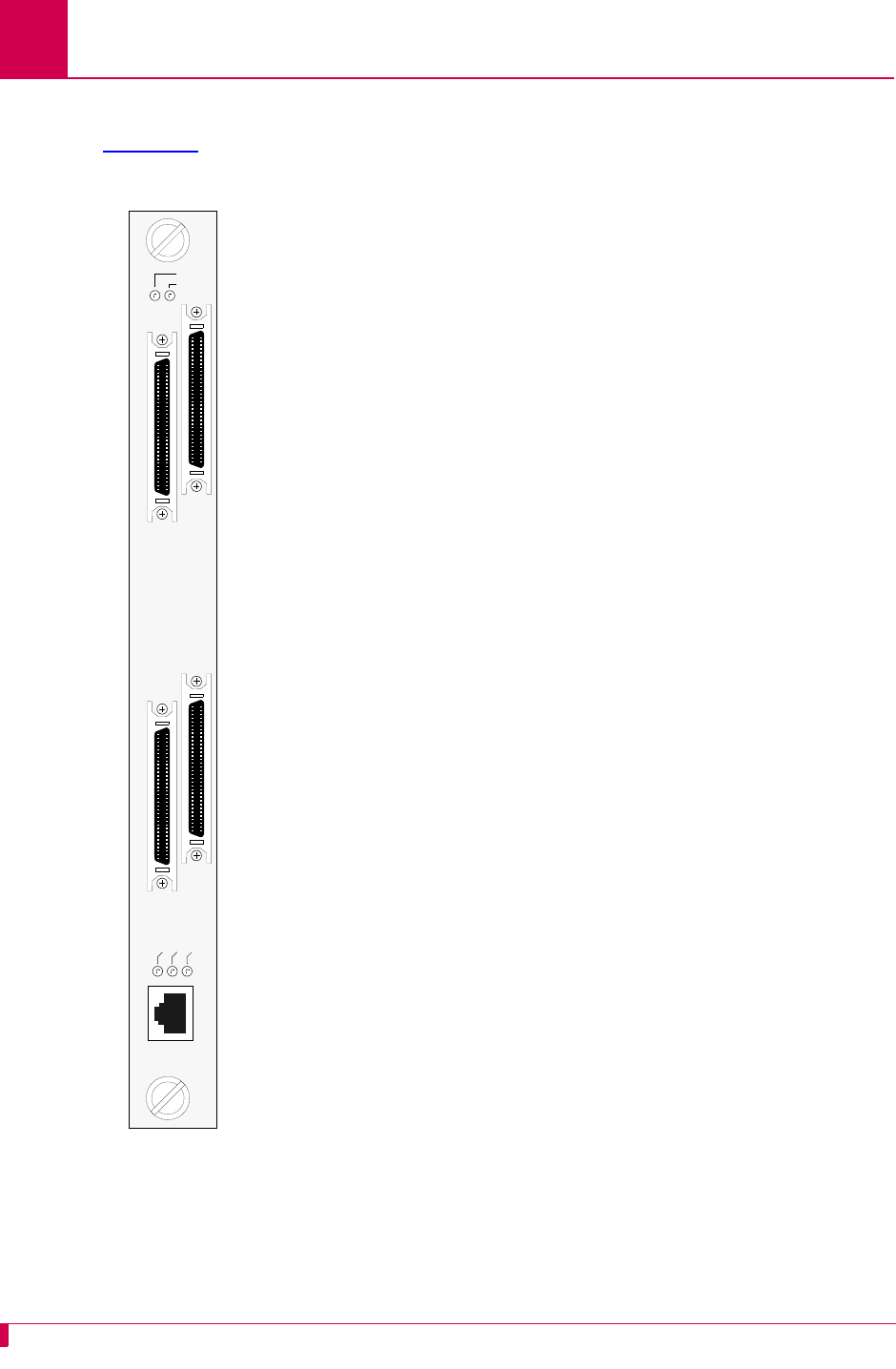
Front Panel Components
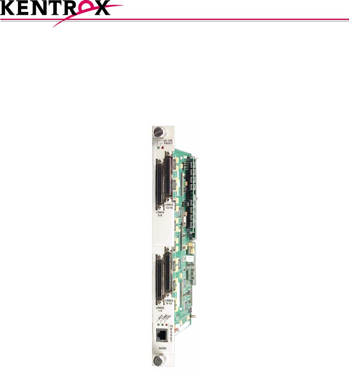
Figure 1-1 displays the AI296 front panel components.
Figure 1-1
AI296
DC OK LED Illuminates green when +5 Volts are
present.
FAULT LED Illuminates red if the card fails.
LINKS 5-8 Connector Provides four asynchronous, HDLC-
Bridge, PPP or X.25 ports.
LINKS 13-16 Connector Provides four asynchronous, HDLC-
Bridge, PPP or X.25 ports.
LINKS 1-4 Connector Provides four asynchronous, HDLC-
Bridge, PPP or X.25 ports.
LINKS 9-12 Connector Provides four asynchronous, HDLC-
Bridge, PPP or X.25 ports.
ACT LED Illuminates green when the card is
transmitting or receiving packets.
LINK LED Illuminates green when valid link integrity
pulses are being received.
COL LED Illuminates red when collisions are
detected.
10BASET Connector Specifies the external 10BaseT port
connector.
DC OK
FAULT
LINKS
5-8
LINKS
13-15
LINKS
1-4
LINKS
9-12
ACT
LINK
COL
10
B
A
S
E
T
AI296

AI296 Version 9.8x User’s Guide
Product Description: Technical Specifications
1-7
Technical Specifications
Table 1-1 lists the AI296 technical specifications.
Table 1-1 Technical Specifications
Component Description
I/O Ports 16 asynchronous, HDLC-Bridge, PPP or X.25 (selectable
per port during configuration)
Note: Individual ports are derived by using a CAB257 cable
assembly for each connector or by using the Model
DP196 distribution panel.
Port Speed 300 bps to 128 Kbps or external clocking (selectable per port
during configuration)
Electrical Interfaces RS-232, RS-530, and V.35 (selectable per port during
configuration)
Installation Requires one slot in an AI chassis (can be hot swapped)
Current Draw 4.2 A at +5 VDC, maximum
Compliance For use with AI UL Listed AIswitch Series Chassis.
AI296 Version 9.8x User’s Guide
Product Description: Individual Port Access
1-8
Individual Port Access
Individual ports are accessed by using a cable assembly or a distribution panel. AI296
uses the following components to derive ports:
zCAB257 Cable
zDP196 Distribution Panel
CAB257 Cable
The CAB257 cable has a multi-connector end that provides four DB-25 connectors.
Four CAB257 cables are needed to derive all 16 ports.
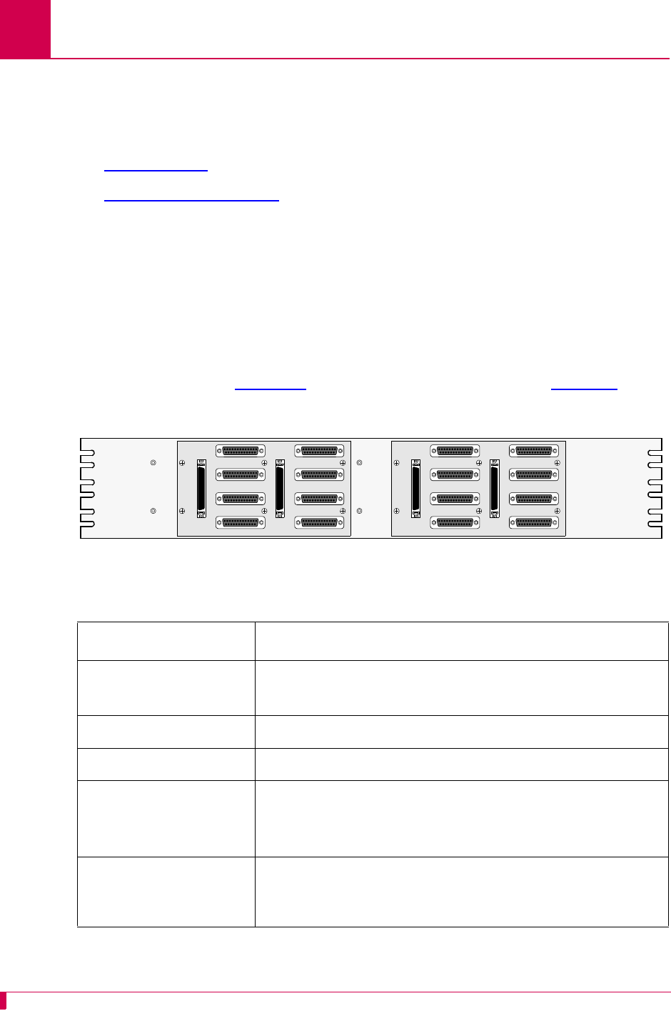
DP196 Distribution Panel
The DP196 distribution panel provides the physical interface for AI296 with sixteen
DB-25 connectors. The distribution panel is available in two sizes for 19-inch or 23-
inch rack installations. Figure 1-2 displays the distribution panel and Table 1-2 lists
the specifications.
Figure 1-2 DP196-19/23 Distribution Panel
Table 1-2 DP196-19/23 Specifications
Description Specification
Mounting DP196-19—Mounts to a 19-inch rack
DP196-23—Mounts to a 23-inch rack
I/O Ports Sixteen DB-25 connectors
Weight (approximately) 2.5 lb. (1.12 kg)
Size Height: 4 in. (10.16 cm)
Width: 19 in.(48.26cm)/23in. (58.42 cm)
Depth: 1.12 in. (2.84 cm)
Cable CAB162—Connects one connector (4 ports) on AI296 to
the distribution panel. Each distribution panel requires
four cables.
LINK 1 LINK 5
LINK 2 LINK 6
LINK 3 LINK 7
LINK 4 LINK 8
LINK 1 LINK 5
LINK 2 LINK 6
LINK 3 LINK 7
LINK 4 LINK 8

AI296 Version 9.8x User’s Guide
Product Description: Individual Port Access
1-9
DB-25 Connectors
Table 1-3 displays pin assignments for the DB-25 connectors on the DP196-19/23
distribution panel.
Figure 1-3 DB-25 connector Pin Assignments
Table 1-3 displays the DP196-19/23 pin assignment specifications.
Table 1-3 DP196-19/23 Pin Assignment Specifications
Pin Signal Direction
2 TXD- Output
3 RXD- Input
4 RTS- Output
5 CTS- Input
7 Signal GND ----
8 DCD- Input
9 RXC+ Input
10 DCD+ Input
12 TXC+ Either
13 CTS+ Input
14 TXD+ Output
15 TXC- Either
16 RXD+ Input
17 RXC- Input
Pin 25
Pin 1 Pin 14
Pin 13

AI296 Version 9.8x User’s Guide
Product Description: Individual Port Access
1-10
The following characteristics apply to pin assignments:
zAny pin assignment not referenced on a connector is not connected.
zSignals with a (-) sign after them are used when RS-232 is selected.
zSignals with both (+) and (-) after them are used when RS-530, V.35, or V.11 are
selected.
zWhen RS-530 is selected, both the (+) and the (-) signals are used. The DSR is
only supported in RS-232 mode. There is no DSR+ signal.
Note: The pin assignments also apply to CAB257.
RJ45 10BaseT Connectors
Figure 1-4 displays the RJ45 10BaseT connector.
Figure 1-4 RJ45 10BaseT Connector on an AI296 Front Panel
Figure 1-4 lists the specifications for the RJ45 10BaseT connector.
CAB182 cables connect network elements to the individual connectors on the
distribution panel (straight through applications).
19 RTS+ Output
20 DTR- Output
23 DTR+ Output
Table 1-4 RJ45 10BaseT Connector Specifications
Pin Signal Direction
1 TD+ Output
2 TD- Output
3 RD+ Input
6 RD- Input
Table 1-3 DP196-19/23 Pin Assignment Specifications (Continued)
Pin Signal Direction
Pin 1 Pin 8
AI296 Version 9.8x User’s Guide
Product Description: Typical Applications
1-11
Typical Applications
AI296 is used primarily for X.25 trunking and connecting different types of network
elements. The following applications are discussed in this section:
zAsynchronous to TCP/IP Application
zIP Over X.25 Networks
zMixed Asynchronous and X.25 Networks
zX.25 to TCP/IP Application
zX.25 Trunking
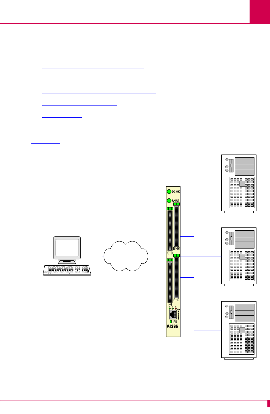
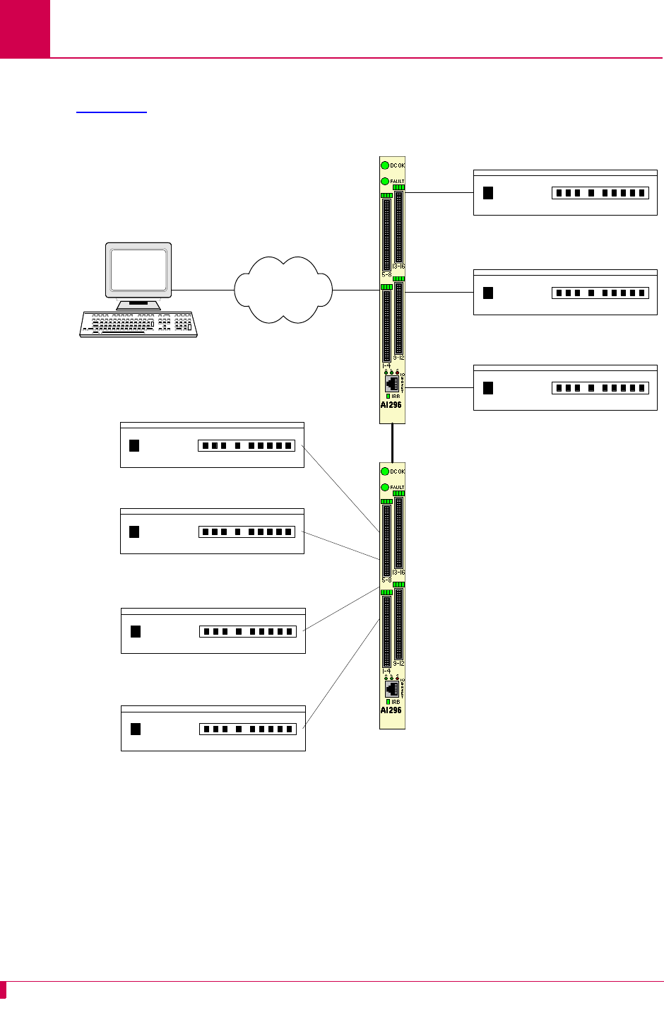
Asynchronous to TCP/IP Application
Figure 1-5 illustrates an asynchronous to TCP/IP application.
Figure 1-5 Asynchronous to TCP/IP Application
Asynchronous NE
Asynchronous NE
Asynchronous NE
Operating Support System
AI296
IP Network
AI296 Version 9.8x User’s Guide
Product Description: Typical Applications
1-12
The following events occur in Figure 1-5:
zThe OSS sends TCP/IP calls to AI296.
zAI296 routes the TCP/IP calls to an asynchronous NE using an asynchronous
port.
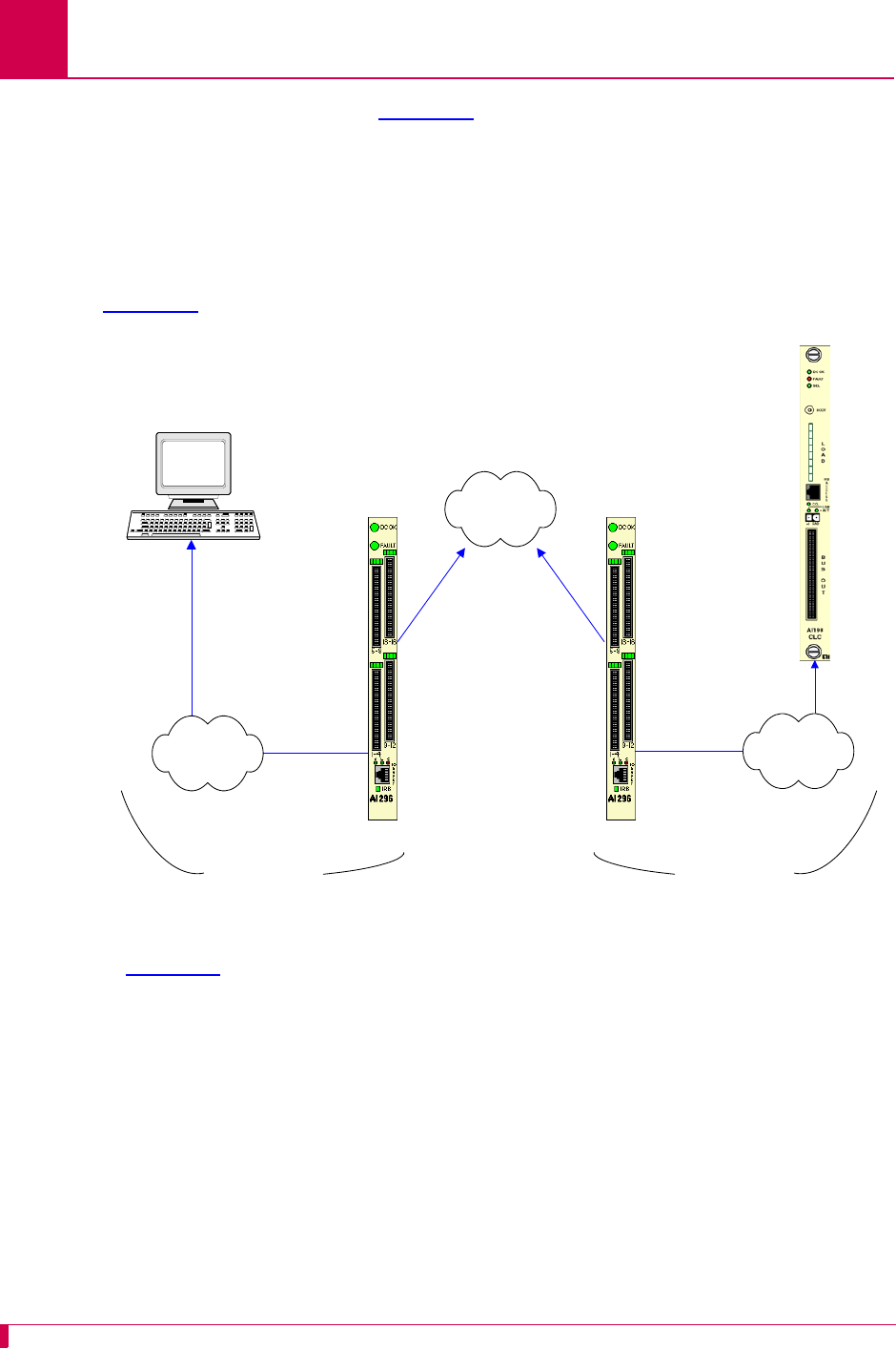
IP Over X.25 Networks
Figure 1-6 illustrates a common IP over X.25 application.
Figure 1-6 IP Over X.25 Network
In Figure 1-6, AI296 is used to tunnel IP traffic through an X.25 network. AI296 can be
configured to encapsulate IP packets, making it possible to achieve IP connectivity
across a legacy X.25 network. The most common application for this functionality is to
transport SNMP management information across an X.25 network.
Important: IP/X.25 transport works only over SVCs.
AI296 AI296
SNMP
Manager SNMP
Manageable
Device
(example
AI198)
IP Over Ethernet IP Over Ethernet
IP Network IP Network
X.25 Packet
Network

AI296 Version 9.8x User’s Guide
Product Description: Typical Applications
1-13
Figure 1-6 on page 1-12 illustrates the following events:
zThe SNMP Network Manager (for example, AppliedView) sends TCP/IP calls over
an IP/Ethernet network to AIswitch (AI296).
zAI296 encapsulates the TCP/IP calls within X.25 SVC calls and sends them
through the X.25 packet network.
zThe X.25 packet network sends the X.25 calls to a remote AIswitch (AI296).
zThe remote AI296 returns the X.25 calls to TCP/IP calls based on its static routing
tables.
zAI296 sends the TCP/IP calls over the IP/Ethernet network to the
SNMP-managed device (for example, AI198).
AI296 Version 9.8x User’s Guide
Product Description: Typical Applications
1-14
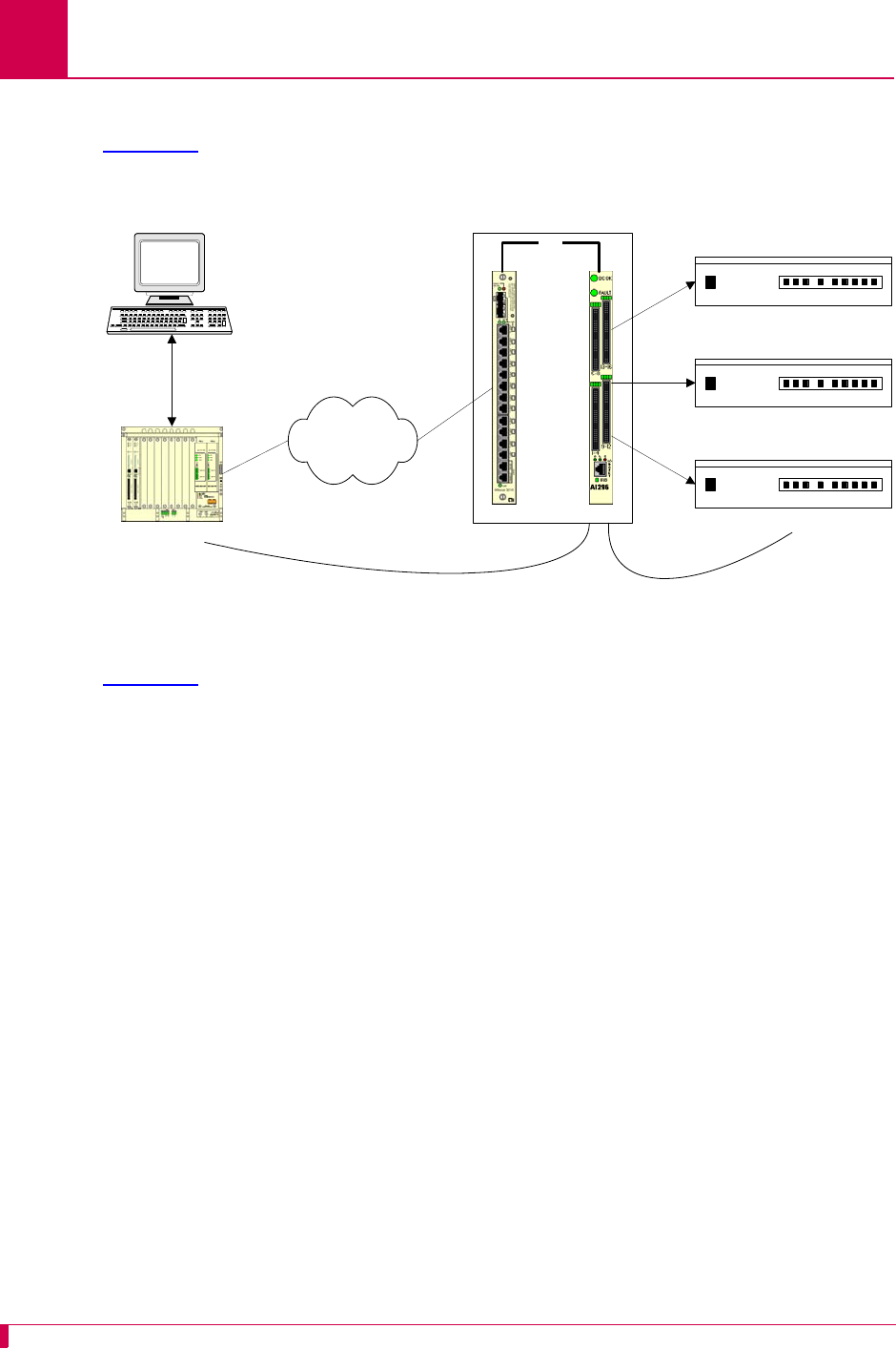
Mixed Asynchronous and X.25 Networks
Figure 1-7 illustrates both X.25 network elements and asynchronous network
elements connected to a remote OSS using a single X.25 trunk.
Figure 1-7 Mixed Asynchronous and X.25 Network
X.25 Packet
Network
DDM 2000
FLM 150
Titan DACS
DDM 2000
FLM 150
Titan DACS
AI296
AI296
Operating
Support System
Asynchronous NE
IRB

AI296 Version 9.8x User’s Guide
Product Description: Typical Applications
1-15
Figure 1-7 illustrates the following events:
zThe OSS sends X.25 calls through an X.25 packet network to AI296.
zAI296 makes call routing decisions based on the AI198 routing alias.
zAI296 sends local X.25 calls directly to the attached NEs.
zThe local AI296 converts local X.25 calls to TCP/IP calls and routes them over the
IRB to a remote AI296. Routing is based on the routing aliases configured in
AI198.
zThe remote AI296 sends asynchronous calls to the attached asynchronous NEs.
AI296 Version 9.8x User’s Guide
Product Description: Typical Applications
1-16
X.25 to TCP/IP Application
Figure 1-8 illustrates a common X.25 to TCP/IP application. X.25 network elements
are connected to a router network using a TCP/IP LAN.
Figure 1-8 X.25 to TCP/IP Application
Figure 1-8 illustrates the following events:
zThe OSS sends X.25 calls to AIswitch.
zAIswitch converts X.25 calls to TCP/IP calls and sends them over the router
network.
zThe router network carries the TCP/IP calls to AIfocusTM.
zAIfocus sends the TCP/IP calls over the IRB to AI296.
zBased on the AI198 routing alias, AI296 converts the TCP/IP calls to X.25 calls.
zAI296 sends X.25 calls to the attached X.25 NEs.
Like other AIswitch line cards, AI296 terminates X.25 connections and extracts the
data from them. Unlike other line cards, AI296 can convert the X.25 connections to
TCP/IP connections across the IRB. The ultimate destination for these TCP/IP
connections may be one of the following:
zAn IRB-connected line card in the same chassis, such as another AI296 or an
AI193-TXTM
zA locally connected TCP/IP host
zA remote TCP/IP host, indirectly connected to AIswitch using a router network.
When AI296 establishes a TCP/IP connection to an external device, the IP packets
are exported from AIswitch by AIfocus or by an AI router.
AIswitch
Operating
Support System X.25 NE
X.25 NE
X.25 NE
IRB
AIfocus AI296
AIswitch
TCP/IP Network
X.25
TCP/IP X.25

AI296 Version 9.8x User’s Guide
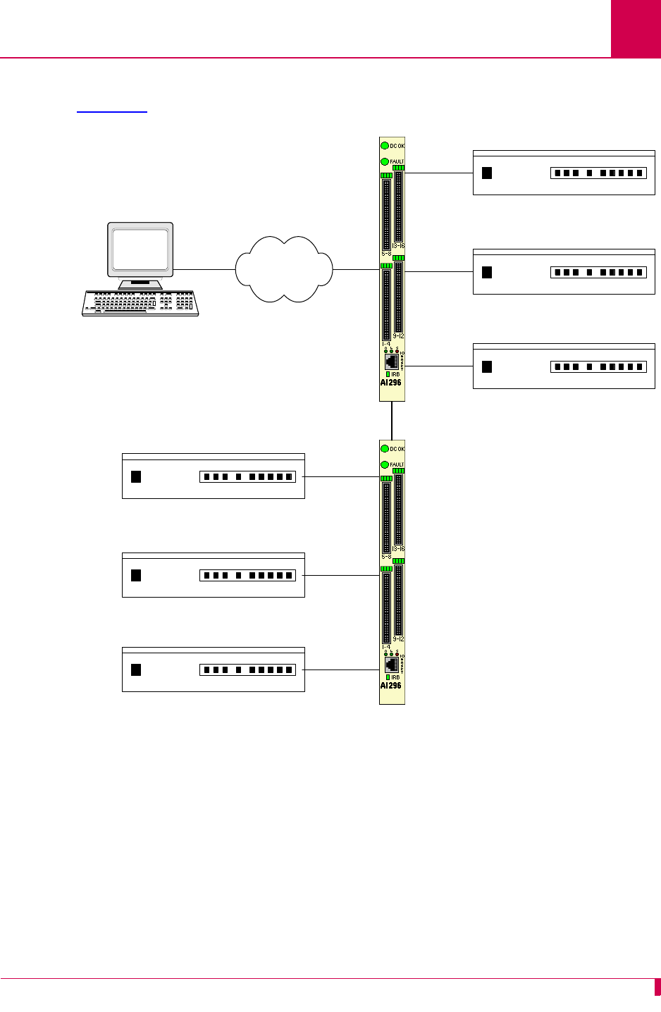
Product Description: Typical Applications
1-18
Figure 1-9 illustrates the following events:
zThe OSS sends X.25 calls through an X.25 packet network (over an X.25 trunk) to
AI296.
zAI296 makes call routing decisions based on the AI198 routing alias.
zAI296 sends local X.25 calls directly to its attached NEs. X.25 NEs are connected
to the OSS with a single X.25 trunk.
zAI296 converts local X.25 calls to TCP/IP calls and sends them over the IRB to a
remote AI296.
zThe remote AI296 sends remote X.25 calls directly to its attached network
elements.


AI296 Version 9.8x User’s Guide
Using the AI198TM Menu System: Accessing the Menu System
2-2
Accessing the Menu System
To access the AI198 menu system:
1. Log into AI198.
2. At the prompt, enter menu. The Main Menu appears.
>menu
Main Menu
01+Configure options affecting the system as a whole
02+Create, delete, or modify a destination name
03+Display all destination names
04+Configure cards
05+Set or remove connection restrictions based on port numbers
06+Display all connection restrictions
07+Configure slot density
08+Configure the alias translation table
09+Display the list of alias translation entries
10+Configure the BOOTP table
21 Exit the configuration menu system
Enter item number and optional ",value" then push <CR> key
>

AI296 Version 9.8x User’s Guide
Using the AI198TM Menu System: Navigating the Menu System
2-3
Navigating the Menu System
Menu Numbering Structure
All menus accessed from the Main Menu are identified with a numerical reference at
the top right corner of the menu screen. This numerical reference specifies the
location within the menu system. Each digit in the menu number represents a menu
item that was previously selected. For example, Menu 4.2 indicates that menu item 4
and 2 were selected.
Types of Menu Items
The following four types of menu items are available:
zSubmenus
zToggles
zData
zFunctions
>2
Menu 4.2
01 Configure as Empty Slot
02+Configure as AI183/AI185 standard 4/16 port card
03+Configure as AI193/194 Ethernet card with slot expansion of-----
04+Configure as AI192/196 X.25 network card with slot expansion of--------
05+Configure as ASP or Advanced Smart Line Card with slot expansion of--------
06 Configure as AI196-I network card with LocalView
07 Configure as AI2524 Router card
08 Configure as AI294 Ethernet Switch card
09+Configure as AI196-I network interface card with menu support
10 Configure as Independent Smart Line Card
11+Configure as AI296 network interface card
12+Configure as AI192/196 with full menu support and slot expansion of--------
13+Configure as AI285 network interface card
14+Configure as AI232 network interface card
15 Configure as AI Modem
16 Configure as AIFlex Fiber LAN Extender Card
17 Configure as AI120 Card
18 Configure as AIE1 Card
19 Configure as AITC Card
20 Next Page
21 Exit this menu with no changes
Enter item number and optional ",value" then push <CR> key
>

AI296 Version 9.8x User’s Guide
Using the AI198TM Menu System: Navigating the Menu System
2-4
Submenus
Submenus go to deeper levels in the menu hierarchy. They provide additional
configuration menus. Menu items that contain submenus have a plus sign (+) next to
their menu item number. In this example, menu item 02 will display a submenu.
Some submenus require a selection from a list and then re-display the previous menu
showing the selection. Other submenus have their own submenus that request
additional information. After saving the entries, the top-level menu re-appears.
Toggles
Toggles display two or more values that can be selected for a parameter. Toggles
have an asterisk (*) next to their menu item number. Entering the menu item number
toggles to the next selection.
In this example, menu items 06 and 07 are toggles.
For 06*TCP Default Window Size, the user can toggle between values 200, 512, 1024, and
2048. For 07*TCP Send Ahead, the user can toggle between ON and OFF.
Data
Data menu items request text entries (such as destination names and card
descriptions) or numeric values (such as port numbers and IP addresses). To enter
information in a data menu item, enter the menu item number followed by a comma
(or a space) and the configuration information.
In this example, the menu item requires an IP address entry.
To enter an IP address of 172.016.002.043, enter the following:
1,172.016.002.043
The menu re-appears with the entered IP address.
To change configuration data that has been entered for a menu item, enter the menu
item number followed by a comma and the new data.
02+Configure as AI232 network interface card
06*TCP Default Window Size (200, 512, 1024, 2048)-------------------------- 200
07*TCP Send Ahead-----------------------------------------------------------OFF
01 IP Address (0.0.0.0 - 255.255.255.254)-----------------------000.000.000.000
01 IP Address (0.0.0.0 - 255.255.255.254)-----------------------172.016.002.043

AI296 Version 9.8x User’s Guide
Using the AI198TM Menu System: Navigating the Menu System
2-5
Tip: To change a typed entry, use BACKSPACE to back up to the desired position in
the text and retype the changes. However, once the user presses ENTER,
changes can be made only by selecting that menu item and re-entering the
data.
Functions
Menu item functions appear at the bottom of each menu. This example displays menu
items that can appear and Table 2-1 describes them.
17 Display first page
18 Next page
19 Delete entry
20 Save the changes made
21 Exit this menu with no changes
Enter item number and optional ",value" then push <CR> key
>
Table 2-1 Menu Item Descriptions
Menu Item Description
17 Displays the first page of a menu.
18 Displays additional pages of a menu.
19 Deletes information for a specified entry.
20 Saves the entered information and re-displays the previous related
menu.
Important: Configuration entries take effect only after every screen
has been saved going back to the main menu.
21 Exits a menu without saving changes. All items on the menu return to
the previously configured values.

AI296 Version 9.8x User’s Guide
Using the AI198TM Menu System: Exiting the Menu System
2-6
Exiting the Menu System
To exit the menu system:
1. Access the Main Menu.
2. Enter 21. The command prompt appears.

3-1
3
AI296 Local Menu System
This chapter provides information on the configuration and navigation of the AI296 menu system.
This system offers on-board configuration capabilities similar to those available in the AI198
menu system. The AI296 menu system is available when the card is operating in both switch
mode and standalone mode.
Guide to this Chapter
Identifying AI296 Menu System Security Options
Logging Into AI296
Accessing the Local Menu System
Navigating the Local Menu System
Accessing the Help Menu
Exiting the Local Menu System

AI296 Version 9.8x User’s Guide
AI296 Local Menu System: Identifying AI296 Menu System Security Options
3-2
Identifying AI296 Menu System Security Options
AI296 has a variety of security options, including:
zMultilevel User Name and Password Security
zRADIUS Authentication
zTACACS+ Authentication
zPPP Authentication Protocols (PAP and CHAP)
Multilevel User Name and Password Security
Up to 10 configurable user account profiles can be assigned to an AI296 user. Five
system profiles are available for providing various levels of user access. For more
information about user profiles, refer to command profile on page 1-103.
RADIUS Authentication
RADIUS authentication verifies user login information against valid user information in
a database on a centralized RADIUS authentication server. A primary and secondary
RADIUS server are configurable to provide secure access for an entire AI296
network. AI296 RADIUS authentication is available for Telnet, asynchronous, and
synchronous ports. For more information on RADIUS authentication, refer to section
RADIUS Configuration on page 1-19.
TACACS+ Authentication
TACACS+ authentication verifies user login information against the user’s permission
level on a TACACS+ server. Up to 9 TACACS+ servers are configurable to provide
secure access for an entire AI296 network. AI296 TACACS+ authentication is
available for Telnet, asynchronous, and FTP connections. For more information on
TACACS+ authentication and server configuration, refer to the following commands:
zaaa
ztacacs
ztacacs server
PPP Authentication Protocols (PAP and CHAP)
All asynchronous and synchronous PPP links are configurable to use either PAP or
CHAP PPP authentication protocols. PAP establishes peer identity using a 2-way
handshake that is done only upon initial link establishment. CHAP performs a 3-way
handshake upon initial link establishment, then proceeds to verify the link with 3-way
handshakes at random intervals. CHAP also encrypts the user’s password over the
PPP link to provide added security.

AI296 Version 9.8x User’s Guide
AI296 Local Menu System: Logging Into AI296
3-3
Logging Into AI296
Log into AI296 with a Telnet connection or with any of AI296’s asynchronous ports
that are configured as Login ports.
Note: ai is the default user ID and password. AI296 prompts you to create a new
user ID and password after the fifth login with the default values. Refer to
command useradd on page 9-118 to create a new user ID and password.
Using a Telnet Connection for Login
Logging in using a Telnet connection requires that AI296 has a configured IP address.
If an IP address has not been configured, refer to Chapter 4: System Configuration to
assign an IP address.
To log into AI296 using a Telnet connection:
1. Power on AI296.
2. Connect the Ethernet network connection to the 10BaseT port on the front panel
of AI296.
3. Telnet to AI296. The login prompt appears.
Note: ai is the default user ID and password. There are five grace period logins.
If after the fifth login a new ID and password have not been created, AI296
prompts you to create a user ID and password. Use the useradd
command described in Chapter 9: AI296 Commands to create a user ID
and password.
4. Enter your user ID. The password prompt appears.
5. Enter your password. The destination menu appears. You are now logged into
AI296.
The following message appears when AI296 is configured to contact a TACACS+
server during authentication:
login: test
Password:
Contacting TACACS+ server. Please wait.

AI296 Version 9.8x User’s Guide
AI296 Local Menu System: Logging Into AI296
3-4
The following message appears when AI296 is configured to contact a TACACS+
server during authentication, but the contact attempt fails:
Note: Five consecutive failed login attempts generate an SNMP trap and a log
message saying that the login failed. Also, an entry appears in the log file with
text stating Warning:
x
consecutive failed login attempts where
x
is the number
of consecutive failed login attempts.
Using an Asynchronous Port for Login
Two tools are required for logging into AI296 using an asynchronous port:
zA PC with terminal emulation software such as HyperTerminal (included with
Windows 95/98/2000/XP) or ProComm.
zTerminal cable with these specifications: null (RS232) cable with DB25 male
connector for AI296 distribution panel connection and appropriate connector for
your PC.
To log into AI296 using an asynchronous port:
1. Set the terminal emulation software to the following settings:
z9600 baud
zNo parity
zEight data bits
zOne stop bit
2. Power on AI296.
3. Connect a PC to port 1 on the DP232 distribution panel.
Note: Link 1 on AI296 is enabled and configured for login by default, which
allows access through the link. AI296 may also be accessed through any
asynchronous link that is enabled and configured for login.
4. Press ENTER. The login prompt appears.
5. Enter your user ID. The password prompt appears.
6. Enter your password. The destination menu appears. You are now logged into
AI296.
login: test
Password:
Contacting TACACS+ server. Please wait.
TACACS+ server(s) not responding.

AI296 Version 9.8x User’s Guide
AI296 Local Menu System: Logging Into AI296
3-5
The following message appears when AI296 is configured to contact a TACACS+
server during authentication:
The following message appears when AI296 is configured to contact a TACACS+
server during authentication, but the contact attempt fails:
Note: Five consecutive failed login attempts generate an SNMP trap and a log
message saying that login failed. Also, a new entry will appear in the log
file with text stating Warning:
x
consecutive failed login attempts where
x
is
the number of consecutive failed login attempts.
login: test
Password:
Contacting TACACS+ server. Please wait.
login: test
Password:
Contacting TACACS+ server. Please wait.
TACACS+ server(s) not responding.

AI296 Version 9.8x User’s Guide
AI296 Local Menu System: Accessing the Local Menu System
3-6
Accessing the Local Menu System
To access the AI296 menu session:
1. Log into AI296. Refer to section Logging Into AI296 on page 3-3 for more
information.
2. At the destination menu, enter ai. The AI296 shell prompt appears.
3. Enter menu. The AI296 Main Menu appears.
Note: The Alias Menu is only available when you log into AI296 in standalone mode.
AI296 Main Menu
+ Link Menu
+ Alias Menu
+ System Menu
+ Static Route Menu
....................................................................
: :
: Select the desired menu option using the UP or DOWN arrow key. :
: Then press ENTER or RETURN to continue. :
:..................................................................:
<F1> Help <F4> Close

AI296 Version 9.8x User’s Guide
AI296 Local Menu System: Navigating the Local Menu System
3-7
Navigating the Local Menu System
Arrow keys and keyboard short cuts can be used to navigate through the local menu
system. Refer to Table 3-1 for a list of arrow key movements and keyboard shortcuts.
Note: To use the arrow keys in the menu system, make sure the VT100 arrow keys
are enabled in either your Telnet settings or your terminal emulation program.
Identifying Types of Menu Items
The AI296 local menu system contains data items that let you input information or
toggle between available selections.
Data Entry Items
The following screen shot displays an example of a data entry menu item:
To enter information for a data entry menu item:
1. Move the cursor to the menu item.
Note: If the selected menu item has a range of valid values, that range will
appear in the bottom right of the screen.
2. Enter your data.
To erase existing data for a data entry menu item:
1. Move the cursor to the menu item.
2. Delete the data using BACKSPACE or DELETE and press ENTER.
OR
Enter new data.
Table 3-1 Direction Keys
Direction Keys
Up Use the up arrow key or Press <Ctrl-p>
Down Use the down arrow key or Press <Ctrl-n>
Right Use the right arrow key or Press <Ctrl-f>
Left Use the left arrow key or Press <Ctrl-b>
Link to configure . . . . . . . . . . . . . . . . . . . . . . . . . . . . 1

AI296 Version 9.8x User’s Guide
AI296 Local Menu System: Navigating the Local Menu System
3-8
To save your changes:
zPress F2 (or use the up and down arrow keys to highlight [Send]) and ENTER.
zEnter y to save. If an error message appears, check your work and make changes
as necessary.
zPress CTRL-E to save data entries immediately without being queried to save. If
an error message appears, check your work and make changes as necessary.
Toggle Items
The following screen shot displays an example of a toggle menu item. The selected
option has brackets around it.
To select a value for a toggle menu item:
1. Move the cursor to the menu item.
2. Highlight the option you want to select and press ENTER. The brackets move to
that option.
To save your changes:
zPress F2 (or use the up and down arrow keys to highlight [Send]) and ENTER.
zEnter y to save. If an error message appears, check your work and make changes
as necessary.
zPress CTRL-E to save data entries immediately without being queried to save. If
an error message appears, check your work and make changes as necessary.
Link state . . . . . . . . . . . . . . . . . . . . . . . . . . [Up] Down

AI296 Version 9.8x User’s Guide
AI296 Local Menu System: Accessing the Help Menu
3-9
Accessing the Help Menu
The AI296 help menu lists all available keyboard codes and function keys with their
associated purposes. The help menu can be accessed by doing one of the following
things:
zPressing F1 and ENTER
zSelecting Help on the menu and ENTER
zPressing ESC-1 and ENTER.
The following example displays the first page of the local menu system help screen:
Navigation Help Page 1 of 4
This screen displays when you press the <F1> key or if you enter an invalid key-
stroke from the Main Menu. The following keyboard function keys are programmed
to allow you to enter or change data in menus:
<F1>; <F2>; <F4>; UP Arrow; DOWN Arrow; LEFT Arrow; RIGHT Arrow
If you can not locate these keys on your keyboard, use the following keyboard
equivalent codes to provide the same functionality:
Keyboard Code Function Key Purpose
Esc 1 <F1> HELP - displays this help screen from any menu.
Esc 2 <F2> SEND - transmits the currently displayed data. You
are given a confirmation prompt before the actual
transmittal of data occurs. When you press the <F2>
key, the RIGHT and LEFT arrow keys can then be used
to access the other commands.
Press SPACE BAR to continue, or 'q' to quit

AI296 Version 9.8x User’s Guide
AI296 Local Menu System: Exiting the Local Menu System
3-10
Exiting the Local Menu System
To exit the local menu system and save all changes:
1. Select <F2> Send and press ENTER.
The following prompt appears:
Save changes? (y/n)
2. Save the changes:
y
3. Select <F4> Close and press ENTER until you are out of the menu system.
To exit the local menu system without saving changes, execute step 3.
Note: Entering <CTRL> + R takes you directly to the main menu.

4-1
4
System Configuration
This chapter provides information on configuring AI296 system settings with the AI198 menu
system and the AI296 local menu system. To configure AI296 with the AI198 menu system, the
AI198 software must be at version 1.90 or later. The AI198 menu system settings take effect only
when AI296 is operating in switch mode (non-standalone mode).
Guide to this Chapter
General System Properties Configuration
RADIUS Configuration
TACACS+ Configuration
SNMP Configuration
Static Route Configuration
TID to Modem Mux Configuration
Time Configuration

AI296 Version 9.8x User’s Guide
System Configuration: General System Properties Configuration
4-2
General System Properties Configuration
General system properties are configurable at the first level of the AI198 and AI296
System menu. The following menu items can be configured:
zDestination Menu Break Sequence
zEthernet Port Settings
zFTP Port
zIP Settings
zPassive Link Settings
zSystem Prompt
zTCP Settings
zTelnet Port
Destination Menu Break Sequence
Description
This menu item sets the character sequence that lets the user exit a connection from
the destination menu.
Format
Destination menu break sequences take the following format:
attention_keystroke
[
delay_start
,
delay_end
]
next_character
attention_keystroke
Defines the keystroke that indicates that a break
sequence is coming. Valid values are:
z<
x
> where
x
represents the decimal ASCII value
of the keystroke. For example, enter <9> to
represent the TAB key.
z<c>
x
where <c> represents the CTRL key and
x
represents the actual key name. For example,
enter <c>^ to represent CTRL+SHIFT+6.
z<c><
x
> where <c> represents the CTRL key and
x
represents the decimal ASCII value of the actual
key name. For example, enter <c><9> to represent
CTRL+TAB.
delay_start
Defines the amount of time (in seconds) you must wait
before entering the next character. Valid values are
integers from 0 to 8.

AI296 Version 9.8x User’s Guide
System Configuration: General System Properties Configuration
4-3
Note: You can include multiple characters with delays between each in the break
sequence. For example, <c>^[1,5]x[0,9]k is a valid entry.
Menu Item Type
Data
Configuration in the AI198 Menu System
1. Access Menu 4.2.11 pg 2.
2. From Menu 4.2.11 pg 2, enter 3, and the desired destination menu break
sequence. The maximum length is 44 characters. The default is <c>^[1,5]x.
This example displays item 03 Destination Menu Break Sequence configured as
<c>^[2,6]x.
delay_end
Defines the amount of time (in seconds) before which
you must enter the next character. Valid values are
integers from 1 to 9.
Note: If you do not enter the next character within the
configured time frame, then both the
attention_keystroke
and
next_character
values are treated as data and forwarded.
next_character
Defines the next character in the sequence. Valid
values are:
z<
x
> where
x
represents the decimal ASCII value
of the keystroke. For example, enter <9> to
represent the TAB key.
z<c>
x
where <c> represents the CTRL key and
x
represents the actual key name. For example,
enter <c>^ to represent CTRL+SHIFT+6.
z<c><
x
> where <c> represents the CTRL key and
x
represents the decimal ASCII value of the actual
key name. For example, enter <c><9> to represent
CTRL+TAB.
>3,<c>^[2,6]x
Menu 4.2.11 pg 2
01*10 Base T Ethernet-------------------------------------------------------OFF
02+Radius Configuration Menu
03 Destination Menu Break Sequence-----------------------------------<c>^[2,6]x

AI296 Version 9.8x User’s Guide
System Configuration: General System Properties Configuration
4-4
Configuration in the AI296 Local Menu System
1. Access the System Menu.
2. Enter a character sequence for Destination Menu Break Sequence. Maximum length
is 44 characters. The default is <c>^[1,5]x.
The following example displays item Destination Menu Break Sequence set to <c><33>.
Ethernet Port Settings
Description
The Ethernet port settings are configured using two menu items:
z10BaseT Ethernet—Enables or disables the 10BaseT Ethernet port on the front
panel of AI296.
zDual Ethernet—Enables or disables simultaneous operation of the faceplate
mounted 10BaseT Ethernet port and the IRB.
Note: When the dual Ethernet setting is enabled, the 10BaseT Ethernet setting
has no effect on AI296 operation.
Menu Item Type
Toggle for both menu items
Configuration in the AI198 Menu System
1. Access Menu 4.2.11 pg 2.
2. For 01*10 Base T Ethernet, enter 1 to select OFF or ON. The default is OFF.
3. For 07*Dual Ethernet, enter 7 to select OFF or ON. The default is OFF.
This example displays 01*10 Base T Ethernet set to ON and 07*Dual Ethernet set to OFF.
System Menu
System Prompt . . . ................................................. [232]
Destination Menu Break Sequence . . . . . . . ..................... <c><33>
>7
Menu 4.2.11 pg 2
01*10 Base T Ethernet------------------------------------------------------- ON
02+Radius Configuration Menu
03 Destination Menu Break Sequence-----------------------------------<c>^[1,5]x
04+TACACS Configuration Menu
05 TCP Outgoing Connection Timer (2-360s)-----------------------------------075
07*Dual Ethernet (On, Off)--------------------------------------------------OFF

AI296 Version 9.8x User’s Guide
System Configuration: General System Properties Configuration
4-5
Configuration in the AI296 Local Menu System
1. Access the System Menu.
2. For 10 Base T Ethernet, select Off or On. The default is off when running in switch
mode. The default is on when running in standalone mode.
3. For Dual Ethernet, select Off or On. The default is Off.
This example displays 10 Base T Ethernet set to ON and Dual Ethernet set to OFF.
FTP Port
Description
This menu item sets the FTP server port number.
Menu Item Type
Data
Configuration in the AI198 Menu System
1. Access Menu 4.2.11.
2. For 16 FTP port number, enter 16, and the FTP server port number. Valid values are
1 to 65534. The default is 21.
System Menu
System Prompt . . . ................................................. [232]
Destination Menu Break Sequence . . . . . . . ..................... <c><33>
TCP Default Window Size . . . . . . . . . . [200] 512 1024 2048
TCP Send Ahead . . . . . . . . . . . . . . . . . . . . . . . On [Off]
Telnet Port . . . . . . . . . . . . . . . . . . . . . . . . . . . . ... 23
FTP Port . . . . . . . . . . . . . . . . . . . . . . . . . . . . . . ... 21
10 Base T Ethernet . . . . . . . . . . . . . . . . . . . . . Off [On]
Dual Ethernet . . . . . . . . . . . . . . . . . . . . . . . [Off] On

AI296 Version 9.8x User’s Guide
System Configuration: General System Properties Configuration
4-6
This example displays 16 FTP port number set to 220.
Configuration in the AI296 Local Menu System
1. Access the System Menu.
2. For FTP Port, enter the desired FTP port value. Valid values are from 0 to 65534.
This example displays FTP Port set to 1752.
IP Settings
Description
The IP settings are configurable using five menu items in the CLC menu or via a shell
command on AI296. The configurable values are:
zIP address
zIP address range
zIP subnet mask
zPrimary IP router address
zSecondary IP router address.
>16,220
Menu 4.2.11 pg 1
01 IP Address (0.0.0.0 - 255.255.255.254)-----------------------010.040.057.015
02 IP Address Range (1 - 255)-----------------------------------------------001
03 IP Subnet Mask (0.0.0.1 - 255.255.255.254) ------------------255.255.000.000
04 Primary IP Router Address (0.0.0.0 - 255.255.255.254) -------010.040.000.001
05 Secondary IP Router Address (0.0.0.0 - 255.255.255.254) -----000.000.000.000
06*TCP Default Window Size (200, 512, 1024, 2048)-------------------------- 200
07*TCP Send Ahead-----------------------------------------------------------OFF
08+SNMP System Parameters
09*Bring passive link down when all calls have cleared----------------------OFF
10 Passive link Stay Inactive timer--------------------------------------000060
11 Passive link Standby Mode timer---------------------------------------000025
12+Link Setup
13+IP Over X.25 Subnets
14+IP Static Routes
15 Telnet port number (1..65534)------------------------------------------00023
16 FTP port number (1..65534)---------------------------------------------00220
System Menu
System Prompt . . . ................................................. [232]
Destination Menu Break Sequence . . . . . . . ..................... <c><33>
TCP Default Window Size . . . . . . . . . . [200] 512 1024 2048
TCP Send Ahead . . . . . . . . . . . . . . . . . . . . . . . On [Off]
Telnet Port . . . . . . . . . . . . . . . . . . . . . . . . . . . . ... 23
FTP Port . . . . . . . . . . . . . . . . . . . . . . . . . . . . . . . 1752

AI296 Version 9.8x User’s Guide
System Configuration: General System Properties Configuration
4-7
Menu Item Types
Data
Configuration in the AI198 Menu System
1. Access Menu 4.2.11.
2. For 01 IP Address, enter 1, and the IP address for AI296. The default is
000.000.000.000.
3. For 02 IP Address Range, enter 2, and the number of the IP addresses to be
assigned to AI296. The valid range is 1 to 255.
4. For 03 IP Subnet Mask, enter 3, and the IP subnet mask for AI296. The default is
255.255.255.254.
5. For 04 Primary IP Router Address, enter 4, and the IP address of the primary router
for AI296. The default is 000.000.000.000.
6. For 05 Secondary IP Router Address, enter 5, and the IP address of the secondary
router for AI296. The default is 000.000.000.000.
This example displays:
z01 IP Address set to 10.38.49.12
z02 IP Address Range set to 3
z03 IP Subnet Mask set to 255.255.000.000
z04 Primary IP Router Address set to 010.038.000.001
z05 IP Router Address set to 010.038.000.002
Note: For information about configuring IP setting with shell commands, refer to
commands ip on page 9-56 and ip init on page 9-57.
>5,10.38.0.2
Menu 4.2.11 pg 1
01 IP Address (0.0.0.0 - 255.255.255.254)-----------------------010.038.049.012
02 IP Address Range (1 - 255)-----------------------------------------------003
03 IP Subnet Mask (0.0.0.1 - 255.255.255.254) ------------------255.255.000.000
04 Primary IP Router Address (0.0.0.0 - 255.255.255.254) -------010.038.000.001
05 Secondary IP Router Address (0.0.0.0 - 255.255.255.254) -----010.038.000.002

AI296 Version 9.8x User’s Guide
System Configuration: General System Properties Configuration
4-8
Passive Link Settings
Description
The passive link settings are configured using three menu items. The configurable
values are:
zPassive link down state—Configures standby (DMlock) mode for a passive link.
When this feature is turned on, a passive link will go into DMlock mode after all
calls have cleared. When turned off, a passive link will stay up when all calls have
cleared.
zPassive link stay inactive timer—Sets the number of seconds a passive link waits
for a connection to come up before failing.
zPassive link standby mode timer—Configures the amount of time a link remains in
standby mode before it becomes idle. Immediately after a passive link becomes
inactive, it goes into the standby (DMlock) mode.
Menu Item Types
Toggle for the passive link down state
Data for the passive link stay inactive timer and the passive link standby mode timer
Configuration in the AI198 Menu System
1. Access Menu 4.2.11.
2. For 09*Bring passive link down when all calls have cleared, enter 9 to select ON or
OFF. The default is OFF.
3. For 10 Passive link Stay Inactive timer, enter 10, and a value in seconds for the
passive link stay inactive timer. The minimum value is 25 seconds and the default
is 60 seconds.
4. For 11 Passive link Standby Mode timer, enter 11, and a value in seconds for the
passive link standby mode timer. The minimum value is 5 seconds and the default
is 25 seconds.

AI296 Version 9.8x User’s Guide
System Configuration: General System Properties Configuration
4-9
This example displays:
z09*Bring passive link down when all calls have cleared set to ON
z10 Passive link Stay Inactive timer set to 50
z11 Passive link Standby Mode timer set to 20
Configuration in the AI296 Local Menu System
1. Access the System Menu.
2. For Bring passive links down when all calls have cleared, select Yes or No. The
default is No.
3. For Time to remain inactive after being brought down, enter a value in seconds.
The minimum value is 25 seconds and the default is 60 seconds.
4. For Time to stand by before being brought up, enter a value in seconds. The
minimum value is 5 seconds and the default is 25 seconds.
This example displays:
zBring passive links down when all calls have cleared set to Yes
zTime to remain inactive after being brought down set to 50
zTime to stand by before being brought up set to 20.
>11,20
Menu 4.2.11 pg 1
01 IP Address (0.0.0.0 - 255.255.255.254)-----------------------010.040.057.015
02 IP Address Range (1 - 255)-----------------------------------------------001
03 IP Subnet Mask (0.0.0.1 - 255.255.255.254) ------------------255.255.000.000
04 Primary IP Router Address (0.0.0.0 - 255.255.255.254) -------010.040.000.001
05 Secondary IP Router Address (0.0.0.0 - 255.255.255.254) -----000.000.000.000
06*TCP Default Window Size (200, 512, 1024, 2048)-------------------------- 200
07*TCP Send Ahead-----------------------------------------------------------OFF
08+SNMP System Parameters
09*Bring passive link down when all calls have cleared---------------------- ON
10 Passive link Stay Inactive timer--------------------------------------000050
11 Passive link Standby Mode timer---------------------------------------000020
System Menu
System Prompt . . . ................................................. [296]
Destination Menu Break Sequence . . . . . . . .................. <c>^[1,5]x
TCP Default Window Size . . . . . . . . . . [200] 512 1024 2048
TCP Send Ahead . . . . . . . . . . . . . . . . . . Enabled [Disabled]
Telnet Port . . . . . . . . . . . . . . . . . . . . . . . . . . . . . .. 23
FTP Port . . . . . . . . . . . . . . . . . . . . . . . . . . . . . . . .. 21
10 Base T Ethernet . . . . . . . . . . . . . . . . . . . . . [Off] On
Dual Ethernet . . . . . . . . . . . . . . . . . . . . . . . [Off] On
Bring passive links down when all calls have cleared . . . . [Yes] No
Time to remain inactive after being brought down (sec) . . . . . . . .... 50
Time to stand by before being brought up (sec) . . . . . . . . . . . .... 20

AI296 Version 9.8x User’s Guide
System Configuration: General System Properties Configuration
4-10
System Prompt
Description
This item sets the system prompt value in the CLI.
Menu Item Type
Data
Configuration in the AI198 Menu System
1. Access Menu 4.2.11.
2. For 17 Prompt String, enter 17, and the desired system prompt value. There is no
default prompt string. The maximum length is 64 characters.
This example displays item 17 Prompt String set to NewPrompt.
Configuration in the AI296 Local Menu System
1. Access the System Menu.
2. For System Prompt, enter the desired system prompt.
This example displays System Prompt set to NewPrompt.
>17,NewPrompt
Menu 4.2.11 pg 1
01 IP Address (0.0.0.0 - 255.255.255.254)-----------------------010.040.057.015
02 IP Address Range (1 - 255)-----------------------------------------------001
03 IP Subnet Mask (0.0.0.1 - 255.255.255.254) ------------------255.255.000.000
04 Primary IP Router Address (0.0.0.0 - 255.255.255.254) -------010.040.000.001
05 Secondary IP Router Address (0.0.0.0 - 255.255.255.254) -----000.000.000.000
06*TCP Default Window Size (200, 512, 1024, 2048)-------------------------- 200
07*TCP Send Ahead-----------------------------------------------------------OFF
08+SNMP System Parameters
09*Bring passive link down when all calls have cleared---------------------- ON
10 Passive link Stay Inactive timer--------------------------------------000050
11 Passive link Standby Mode timer---------------------------------------000020
12+Link Setup
13+IP Over X.25 Subnets
14+IP Static Routes
15 Telnet port number (1..65534)------------------------------------------00023
16 FTP port number (1..65534)---------------------------------------------00021
17 Prompt String------------------------------------------------------NewPrompt
System Menu
System Prompt . . . ............................................. NewPrompt

AI296 Version 9.8x User’s Guide
System Configuration: General System Properties Configuration
4-11
TCP Settings
Description
The TCP settings are configured using two menu items. The configurable values are:
zTCP default window size—Sets the TCP default window size for AI296. The window
size specifies how many bytes AI296 will send to another device or how many
bytes another device may send to the AI296 before receiving an
acknowledgement.
Note: A small default window size way slow transfers to and from AI296.
zTCP send ahead—Enables or disables AI296’s ability to send a TCP window without
requiring an acknowledgment. When enabled, acknowledgment is not required.
When disabled, acknowledgment is required.
Menu Item Type
Toggle
Configuration in the AI198 Menu System
1. Access System Menu 4.2.11.
2. For 06*TCP Default Window Size, enter 6 to select 200, 512, 1024, or 2048. The default
is 200.
3. For 07*TCP Send Ahead, enter 7 to select OFF or ON. The default is OFF.
This example displays 06*TCP Default Window Size set to 1024 and 07*TCP Send Ahead set
to ON.
Configuration in the AI296 Local Menu System
1. Access the System Menu.
2. For TCP Default Window Size, select 200, 512, 1024, or 2048. The default is 200.
3. For TCP Send Ahead, select Enabled or Disabled. The default is Disabled.
>7
Menu 4.2.11 pg 1
01 IP Address (0.0.0.0 - 255.255.255.254)-----------------------010.040.057.015
02 IP Address Range (1 - 255)-----------------------------------------------001
03 IP Subnet Mask (0.0.0.1 - 255.255.255.254) ------------------255.255.000.000
04 Primary IP Router Address (0.0.0.0 - 255.255.255.254) -------010.040.000.001
05 Secondary IP Router Address (0.0.0.0 - 255.255.255.254) -----000.000.000.000
06*TCP Default Window Size (200, 512, 1024, 2048)--------------------------1024
07*TCP Send Ahead----------------------------------------------------------- ON

AI296 Version 9.8x User’s Guide
System Configuration: General System Properties Configuration
4-12
This example displays TCP Default Window Size set to 1024 and TCP Send Ahead set to
Enabled.
Telnet Port
Description
This item sets the Telnet port value for AI296.
Menu Item Type
Data
Configuration in the AI198 Menu System
1. Access Menu 4.2.11.
2. For 15 Telnet port number, enter 15, and the desired port number value. Valid
values are 1 to 65534. The default is 23.
This example displays 15 Telnet port number set to 122.
Configuration in the AI296 Local Menu System
1. Access the System Menu.
2. For Telnet Port, enter the desired value. The default is 23.
System Menu
System Prompt . . . ............................................. NewPrompt
Destination Menu Break Sequence . . . . . . . .................. <c>^[1,5]x
TCP Default Window Size . . . . . . . . . . 200 512 [1024] 2048
TCP Send Ahead . . . . . . . . . . . . . . . . . . [Enabled] Disabled
>15,122
Menu 4.2.11 pg 1
01 IP Address (0.0.0.0 - 255.255.255.254)-----------------------010.040.057.015
02 IP Address Range (1 - 255)-----------------------------------------------001
03 IP Subnet Mask (0.0.0.1 - 255.255.255.254) ------------------255.255.000.000
04 Primary IP Router Address (0.0.0.0 - 255.255.255.254) -------010.040.000.001
05 Secondary IP Router Address (0.0.0.0 - 255.255.255.254) -----000.000.000.000
06*TCP Default Window Size (200, 512, 1024, 2048)--------------------------1024
07*TCP Send Ahead----------------------------------------------------------- ON
08+SNMP System Parameters
09*Bring passive link down when all calls have cleared---------------------- ON
10 Passive link Stay Inactive timer--------------------------------------000050
11 Passive link Standby Mode timer---------------------------------------000020
12+Link Setup
13+IP Over X.25 Subnets
14+IP Static Routes
15 Telnet port number (1..65534)------------------------------------------00122

AI296 Version 9.8x User’s Guide
System Configuration: General System Properties Configuration
4-13
This example displays Telnet Port set to 55.
System Menu
System Prompt . . . ............................................. NewPrompt
Destination Menu Break Sequence . . . . . . . .................. <c>^[1,5]x
TCP Default Window Size . . . . . . . . . . 200 512 [1024] 2048
TCP Send Ahead . . . . . . . . . . . . . . . . . . [Enabled] Disabled
Telnet Port . . . . . . . . . . . . . . . . . . . . . . . . . . . . . .. 55

AI296 Version 9.8x User’s Guide
System Configuration: RADIUS Configuration
4-14
RADIUS Configuration
RADIUS authentication verifies user login information against valid user information in
a database on a centralized RADIUS authentication server. A primary and secondary
RADIUS server are configurable to provide secure access for an entire AI296
network. AI296 RADIUS authentication is available for Telnet, asynchronous, and
synchronous ports. The following menu items can be configured for RADIUS:
zServer Settings
zShell/FTP Options
Server Settings
Description
The RADIUS server settings are configured using four menu items for the primary and
secondary server. The configurable values are:
zPrimary/secondary server status—Enables or disables the primary or secondary
server.
zPrimary/secondary server IP address—Defines an IP address for the primary or
secondary server.
zPrimary/secondary server port—Defines the port number for the primary or
secondary server.
zPrimary/secondary server secret—Defines a password for the primary or secondary
server.
Menu Item Types
Toggle for primary/secondary server status
Data for primary/secondary server IP address, server port, and server secret
Configuration in the AI198 Menu System
Note: RADIUS and TACACS+ cannot both be configured at the same time.
Attempting to do this generates an error.
To configure the RADIUS server settings:
1. Access Menu 4.2.11-2.2.
2. For 01*Primary Server Status, enter 1 to select ENABLED or DISABLED. The default is
DISABLED.
3. For 02 Primary Server IP Address, enter 2, and the desired IP address. The default
is 0.0.0.0.

AI296 Version 9.8x User’s Guide
System Configuration: RADIUS Configuration
4-15
4. For 03 Primary Server Port, enter 3, and the desired port number. The default is
1812.
5. For 04 Primary Server Secret, enter 4, and the desired password. The default is
applied.
6. If desired, repeat steps 2 through 5 for the secondary server settings.
This example displays:
z01*Primary Server Status set to ENABLED
z02 Primary Server IP Address set to 050.023.156.012
z03 Primary Server Port set to 122
z04 Primary Server Secret set to hilltop.
Configuration in the AI296 Local Menu System
1. Access the RAS Configuration Menu located under the System Menu.
2. For RADIUS Primary Server Status, select Enabled or Disabled.
3. For IP address, enter an IP address. The default is 0.0.0.0.
4. For Port Number, enter a port number. The default is 1812 for RADIUS servers.
5. For Secret, enter a password. The default is applied.
6. Repeat steps 2 through 5 for the secondary RADIUS server.
This example displays:
zRADIUS Primary Server Status set to Enabled
zIP Address set to 12.33.57.2
zPort Number set to 122
zSecret set to newone.
>4,hilltop
Menu 4.2.11-2.2
01*Primary Server Status (Enabled, Disabled)--------------------------- ENABLED
02 Primary Server IP Address------------------------------------050.023.156.012
03 Primary Server Port (1..65535)-----------------------------------------00122
04 Primary Server Secret------------------------------- hilltop
RAS Configuration Menu
RADIUS Primary Server Status . . . . . . . . . . . [Enabled] Disabled
IP Address . . . . .... 12.33.57.2 Port Number . . . . . 122
Secret . . . .............. newone

AI296 Version 9.8x User’s Guide
System Configuration: RADIUS Configuration
4-16
Shell/FTP Options
Description
This item sets the Shell/FTP option for RADIUS as one of the following:
zEnabled—Enables RADIUS login.
zDisabled—Disables RADIUS login.
zLocal fallback—Enables RADIUS login, but resorts to local login if the RADIUS
login fails.
Note: RADIUS and TACACS+ cannot both be configured at the same time.
Attempting to do this generates an error.
Menu Item Type
Toggle
Configuration in the AI198 Menu System
To configure the shell/FTP RADIUS option:
1. Access Menu 4.2.11-2.2.
2. For 09*Shell/FTP Radius Option, enter 9 to select ENABLED, DISABLED, or LOCAL
FALLBACK. The default is DISABLED.
This example displays 09*Shell/FTP Radius Option set to LOCAL FALLBACK.
Configuration in the AI296 Local Menu System
To configure the shell/FTP RADIUS option:
1. Access the RAS Configuration Menu located under the System Menu.
2. For Shell RAS Option, select Disabled, RADIUS, RADIUS/Fallback. The default is
Disabled.
>9
Menu 4.2.11-2.2
01*Primary Server Status (Enabled, Disabled)--------------------------- ENABLED
02 Primary Server IP Address------------------------------------050.023.156.012
03 Primary Server Port (1..65535)-----------------------------------------00122
04 Primary Server Secret------------------------------- hilltop
05*Secondary Server Status (Enabled, Disabled)-------------------------DISABLED
06 Secondary Server IP Address----------------------------------000.000.000.000
07 Secondary Server Port (1..65535)---------------------------------------01812
08 Secondary Server Secret----------------------------- applied
09*Shell/FTP Radius Option (Enabled, Disabled, Local Fallback)---LOCAL FALLBACK

AI296 Version 9.8x User’s Guide
System Configuration: RADIUS Configuration
4-17
This example displays the shell RAS option set to RADIUS/Fallback.
RAS Configuration Menu
RADIUS Primary Server Status . . . . . . . . . . . [Enabled] Disabled
IP Address . . . . ....... 0.0.0.0 Port Number . . . . 1812
Secret . . . .............. newone
RADIUS Secondary Server Status . . . . . . . . . . Enabled [Disabled]
IP Address . . . . ....... 0.0.0.0 Port Number . . . . 1812
Secret . . . ............. applied
Shell RAS Option: Disabled RADIUS [RADIUS/Fallback]

AI296 Version 9.8x User’s Guide
System Configuration: TACACS+ Configuration
4-18
TACACS+ Configuration
TACACS+ authentication verifies user login information against the user’s permission
level on a TACACS+ server. Up to 9 TACACS+ servers are configurable to provide
secure access for an entire AI296 network. AI296 TACACS+ authentication is
available for Telnet, asynchronous, asynchronous PPP, and FTP connections. The
following menu items can be configured for TACACS+ on the AI198 menu system:
zServer Settings
zShell/FTP Options
Note: TACACS+ is not configurable from the AI296 local menu system. For
information on configuring TACACS+ when logged into AI296, refer to shell
commands aaa on page 9-6, tacacs on page 9-96, and tacacs server on page
9-99.
Server Settings
Description
From the AI198 Menu System, the TACACS+ server settings are configured using
four menu items for the primary and secondary server. The configurable values are:
zPrimary/secondary server status—Enables or disables the primary or secondary
server.
zPrimary/secondary server IP address—Defines an IP address for the primary or
secondary server.
zPrimary/secondary server port—Defines the port number for the primary or
secondary server.
zPrimary/secondary server secret—Defines a password for the primary or secondary
server.
Menu Item Types
Toggle for primary/secondary server status
Data for primary/secondary server IP address, server port, and server secret
Configuration in the AI198 Menu System
To configure the TACACS+ server settings:
1. Access Menu 4.2.11-2.4.
2. For 01*Primary Server Status, enter 1 to select ENABLED or DISABLED. The default is
DISABLED.

AI296 Version 9.8x User’s Guide
System Configuration: TACACS+ Configuration
4-19
3. For 02 Primary Server IP Address, enter 2, and the IP address. The default is
0.0.0.0.
4. For 03 Primary Server Port, enter 3, and the port number. The default is 49.
5. For 04 Primary Server Secret, enter 4, and the password. The default is applied.
6. Repeat steps 2 through 5 for the secondary server settings.
This example displays:
z01*Primary Server Status set to ENABLED
z02 Primary Server IP Address set to 050.023.156.011
z03 Primary Server Port set to 122
z04 Primary Server Secret set to hilltop.
Shell/FTP Options
Description
This item sets the Shell/FTP option for TACACS+ as one of the following:
zEnabled—Enables TACACS+ login.
zDisabled—Disables TACACS+ login.
zLocal fallback—Enables TACACS+ login, but resorts to local login if the
TACACS+ login fails.
Note: RADIUS and TACACS+ cannot both be configured at the same time.
Attempting to do this generates an error.
Menu Item Type
Toggle
Configuration in the AI198 Menu System
Important: Configuration of the shell/FTP TACACS+ option results in privilege level
authorization and supersedes any TACACS+ configuration on the AI296
card.
To configure the shell/FTP TACACS+ option:
1. Access Menu 4.2.11-2.4.
>4,hilltop
Menu 4.2.11-2.4
01*Primary Server Status (Enabled, Disabled)--------------------------- ENABLED
02 Primary Server IP Address------------------------------------050.023.156.012
03 Primary Server Port (1..65535)-----------------------------------------00122
04 Primary Server Secret------------------------------- hilltop

AI296 Version 9.8x User’s Guide
System Configuration: TACACS+ Configuration
4-20
2. For 09*Shell/FTP TACACS Option, enter 9 to select ENABLED, DISABLED, or LOCAL
FALLBACK. The default is DISABLED.
This example displays 09*Shell/FTP TACACS Option set to LOCAL FALLBACK.
>9
Menu 4.2.11-2.4
01*Primary Server Status (Enabled, Disabled)---------------------------DISABLED
02 Primary Server IP Address------------------------------------000.000.000.000
03 Primary Server Port (1..65535)-----------------------------------------00049
04 Primary Server Secret------------------------------- applied
05*Secondary Server Status (Enabled, Disabled)-------------------------DISABLED
06 Secondary Server IP Address----------------------------------000.000.000.000
07 Secondary Server Port (1..65535)---------------------------------------00049
08 Secondary Server Secret----------------------------- applied
09*Shell/FTP TACACS Option (Enabled, Disabled, Local Fallback)---LOCAL FALLBACK

AI296 Version 9.8x User’s Guide
System Configuration: SNMP Configuration
4-21
SNMP Configuration
This section discusses SNMP configuration options. The following configuration
components are available:
zAuthentication Traps
zCommunity Names
zContact Persons
zNode Information
zSNMP Manager
Authentication Traps
Description
This item enables or disables the generation of authentication failure traps by AI296.
When a user enters faulty login information, authentication traps are sent from an
SNMP agent to inform the management station about the incorrect login attempt.
Menu Item Types
Toggle
Configuration in the AI198 Menu System
1. Access Menu 4.2.11.8.
2. For 04*Send authentication traps, enter 4 to select ON or OFF. The default is ON.
The following example displays item 04*Send authentication traps set to ON.
AI296 Local Menu Item Configuration
1. Access the SNMP Menu located under the System Menu.
2. For Send authentication traps, select On or Off. The default is ON.
>4
Menu 4.2.11.8
01 Contact person for this node------------------------------------------------
02 Node name-------------------------------------------------------------------
03 Node location---------------------------------------------------------------
04*Send authentication traps------------------------------------------------ ON

AI296 Version 9.8x User’s Guide
System Configuration: SNMP Configuration
4-22
The following example displays the selection of On for menu item Send authentication
traps.
Community Names
Description
SNMP community names provide embedded password access to MIB contents.
There are three menu items available for configuring AI296 SNMP community name
information:
zRead Community Name—Sets the name that permits read only access to all objects in
the MIB.
zMIB2 Read Community Name—Sets the name that permits read only access to all
objects in MIB2.
zWrite Community Name—Sets the name that permits read and write access to all
objects in the MIB.
Menu Item Types
Data for all menu items
Configuration in the AI198 Menu System
1. Access Menu 4.2.11.8.
2. For 05 Read Community Name, enter 5, and the community name value. The
maximum length is 32 characters. The default value is readonly.
3. For 06 MIB2 Read Community Name, enter 6, and the community name value. The
maximum length is 32 characters. The default value is public.
4. For 07 Write Community Name, enter 7, and the community name value. The
maximum length is 32 characters. The default value is administrator.
SNMP Menu
Contact person for this managed node . . . . . . . . . . . . .
Node name . . . . . . . . . . . . . . . . . . . . . . . . . . ...............
Node location . . . . . . . . . . . . . . . . . . . . . . . . ...............
Send authentication traps . . . . . . . . . . . . . . . . . . [On] Off

AI296 Version 9.8x User’s Guide
System Configuration: SNMP Configuration
4-23
The following example displays:
zItem 05 Read Community Name set to ReadComm.
zItem 06 MIB2 Read Community Name set to MIB2.
zItem 07 Write Community Name set to WriteComm.
AI296 Local Menu Item Configuration
1. Access the SNMP Menu located under the System Menu.
2. For menu item Read Community Name, enter the community name value. The
maximum length is 32 characters. The default value is readonly.
3. For menu item MIB2 Read Community Name, enter the community name value. The
maximum length is 32 characters. The default value is public.
4. For menu item Write Community Name, enter the community name value. The
maximum length is 32 characters. The default value is administrator.
The following example displays:
zItem Read Community Name set to ReadComm.
zItem MIB2 Read Community Name set to MIB2.
zItem Write Community Name set to WriteComm.
>7,WriteComm
Menu 4.2.11.8
01 Contact person for this node------------------------------------------------
02 Node name-------------------------------------------------------------------
03 Node location---------------------------------------------------------------
04*Send authentication traps------------------------------------------------ ON
05 Read Community Name-------------------------------------------------ReadComm
06 MIB2 Read Community Name------------------------------------------------MIB2
07 Write Community Name-----------------------------------------------WriteComm
SNMP Menu
Contact person for this managed node . . . . . . . . . . . . .
Node name . . . . . . . . . . . . . . . . . . . . . . . . . . ...............
Node location . . . . . . . . . . . . . . . . . . . . . . . . ...............
Send authentication traps . . . . . . . . . . . . . . . . . . [On] Off
SNMP Manager #1 . . . . . . . . . . . . . . . . . . . . . . ..... 10.35.0.30
SNMP Manager #2 . . . . . . . . . . . . . . . . . . . . . . ..... 10.35.0.60
SNMP Manager #3 . . . . . . . . . . . . . . . . . . . . . . ..... 10.35.0.20
SNMP Manager #4 . . . . . . . . . . . . . . . . . . . . . . ........ 0.0.0.0
SNMP Manager #5 . . . . . . . . . . . . . . . . . . . . . . ........ 0.0.0.0
Read Community Name . . . . . . . . . . . . . . . . . . . . . ...... ReadComm
MIB2 Read Community Name . . . . . . . . . . . . . . . . . . ........... MIB2
Write Community Name . . . . . . . . . . . . . . . . . . . . ...... WriteComm

AI296 Version 9.8x User’s Guide
System Configuration: SNMP Configuration
4-24
Contact Persons
Description
This item defines the name of the person to contact regarding a specific node.
Menu Item Types
Data
Configuration in the AI198 Menu System
1. Access Menu 4.2.11.8.
2. For 01 Contact person for this node, enter 1, and the desired contact person. The
maximum length is 40 characters.
The following example displays John Doe configured for menu item 01 Contact person
for this node:
AI296 Local Menu Item Configuration
1. Access the SNMP Menu located under the System Menu.
2. For Contact person for this managed node, enter the contact person. The maximum
length is 40 characters.
The following example displays John Doe configured for menu item Contact person for
this managed node:
Node Information
Description
There are two menu items available for configuring node information:
zNode Name—Defines the name of a location on a network.
zNode Location—Defines a location on a network.
Menu Item Types
Data
>1,John Doe
Menu 4.2.11.8
01 Contact person for this node----------------------------------------John Doe
SNMP Menu
Contact person for this managed node . . . . . . . . . . . . ....... John Doe

AI296 Version 9.8x User’s Guide
System Configuration: SNMP Configuration
4-25
Configuration in the AI198 Menu System
1. Access Menu 4.2.11.8.
2. For 02 Node name, enter 2, and the node name. The maximum length is 40
characters.
3. For 03 Node location, enter 3, and a node location description. The maximum
length is 40 characters.
The following example displays the configuration of node name newNode and node
location Office B.
AI296 Local Menu Item Configuration
1. Access the SNMP Menu located under the System Menu.
2. For Node name, enter the node name. The maximum length is 40 characters.
3. For Node location, enter a node location description. The maximum length is 40
characters.
The following example displays the configuration of node name newNode and node
location Office B.
SNMP Manager
Description
An SNMP manager is a combination of monitoring software running on a network
management station (NMS) and the actual device running the software. It collects and
acts on information from the various devices being monitored and/or controlled. The
SNMP manager also periodically polls the devices it is managing to get status
information. AI296 allows for the configuration of up to 5 SNMP managers.
Note: SNMP managers are only configurable when AI296 is in standalone mode.
They are not configurable through the AI198 menu system.
>3,Office B
Menu 4.2.11.8
01 Contact person for this node----------------------------------------John Doe
02 Node name------------------------------------------------------------newNode
03 Node location-------------------------------------------------------Office B
SNMP Menu
Contact person for this managed node . . . . . . . . . . . . ....... John Doe
Node name . . . . . . . . . . . . . . . . . . . . . . . . . . ....... newNode
Node location . . . . . . . . . . . . . . . . . . . . . . . . ...... Office B

AI296 Version 9.8x User’s Guide
System Configuration: SNMP Configuration
4-26
Menu Item Types
Data
AI296 Local Menu Item Configuration
1. Access the SNMP Menu located under the System Menu.
2. For SNMP Manager #1, enter the IP address of the first SNMP manager. The default
is 0.0.0.0.
3. For SNMP Manager #2, enter the IP address of the second SNMP manager. The
default is 0.0.0.0.
4. For SNMP Manager #3, enter the IP address of the third SNMP manager. The default
is 0.0.0.0.
5. For SNMP Manager #4, enter the IP address of the fourth SNMP manager. The
default is 0.0.0.0.
6. For SNMP Manager #5, enter the IP address of the fifth SNMP manager. The default
is 0.0.0.0.
The following example displays:
zSNMP Manager #1 set to 10.65.32.4
zSNMP Manager #2 set to 10.65.32.5
zSNMP Manager #3 set to 10.65.32.6
zSNMP Manager #4 set to 10.65.32.7
zSNMP Manager #5 set to 10.65.32.8
SNMP Menu
Contact person for this managed node . . . . . . . . . . . . .
Node name . . . . . . . . . . . . . . . . . . . . . . . . . . ...............
Node location . . . . . . . . . . . . . . . . . . . . . . . . ...............
Send authentication traps . . . . . . . . . . . . . . . . . . [On] Off
SNMP Manager #1 . . . . . . . . . . . . . . . . . . . . . . ..... 10.65.32.4
SNMP Manager #2 . . . . . . . . . . . . . . . . . . . . . . ..... 10.65.32.5
SNMP Manager #3 . . . . . . . . . . . . . . . . . . . . . . ..... 10.65.32.6
SNMP Manager #4 . . . . . . . . . . . . . . . . . . . . . . ..... 10.65.32.7
SNMP Manager #5 . . . . . . . . . . . . . . . . . . . . . . ..... 10.65.32.8

AI296 Version 9.8x User’s Guide
System Configuration: Static Route Configuration
4-27
Static Route Configuration
AI296 allows for the configuration of static routes using both the AI198 and AI296
menu systems.
IP Address Settings
Description
Static routes are configured with a destination and next hop IP address. The
destination IP address defines the static IP route you want to configure. The next hop
IP address defines the IP address of the router you want the system to use when
trying to reach the destination IP address.
Menu Item Types
Data
Configuration in the AI198 Menu System
1. Access Menu 4.2.11.14.
2. From Menu 4.2.11.14, enter a value from 3 to 11. Menu 4.2.11.14.1 appears.
3. For 01 Destination IP, enter an IP address value.
4. For 02 Next Hop IP, enter an IP address value.
The following example displays the configuration of destination address 84.238.45.2
and next hop address 23.51.93.5.
AI296 Local Menu Item Configuration
1. Access the Static Route Menu.
2. Select [Add]. The IP Static Route Edit Menu appears.
3. For Destination IP Address, enter an IP address value. The default is 1.1.1.1.
4. For Next Hop IP Address, enter an IP address value. The default is 1.1.1.1.
The following example displays the configuration of destination IP address 12.240.54.3
and next hop IP address 12.240.54.4.
>2,023.051.093.005
Menu 4.2.11.14.1
01 Destination IP-----------------------------------------------084.238.045.002
02 Next Hop IP--------------------------------------------------023.051.093.005
IP Static Route Edit Menu
Destination IP Address . . . . . . . . . . . . . . ........... 12.240.54.3
Next Hop IP Address . . . . . . . . . . . . . . . . ........... 12.240.54.4

AI296 Version 9.8x User’s Guide
System Configuration: TID to Modem Mux Configuration
4-28
TID to Modem Mux Configuration
The following are available:
zInactivity Timeout
zInitialization String
zPort Bit Settings
zTID to Route
Inactivity Timeout
Description
This menu item defines the amount of time (in seconds) the Modem Mux connection
must be inactive before it times out.
Menu Item Types
Data
Configuration in the AI198 Menu System
1. Access Menu 4.2.14-2.6.
2. From Menu 4.2.14-2.6, enter a value from 2 to 11. Menu 4.2.14-2.6.1 appears.
3. For 06 Inactivity Timeout, enter 6, and a timeout value. Valid values are from 0 to
100000. The default is 300.
This example displays 06 Inactivity Timeout set to 1500.
AI296 Local Menu Item Configuration
1. Access the TID to Modem Mux Menu located under the System Menu.
2. From the TID to Modem Mux Summary Menu, select [Add TID]. The TID To
Modem Mux Edit Menu appears.
3. For Inactivity Timeout, enter a timeout value. Valid values are from 0 to 100000.
The default is 300.
>6,1500
Menu 4.2.14-2.6.1
01 TID to route--------------------------------------------
02*Port Data Bits (7, 8)------------------------------------------------------8
03*Port Stop Bits (1, 2)------------------------------------------------------1
04*Port Parity (None, Even, Odd)-------------------------------------------None
05 Init String-----------------------------------
06 Inactivity Timeout (0 - 100000)---------------------------------------001500

AI296 Version 9.8x User’s Guide
System Configuration: TID to Modem Mux Configuration
4-29
This example displays Inactivity Timeout set to 1500.
Initialization String
Description
This menu item defines the string that is sent upon indication that there is a device
connected to the port (DSR asserted).
Menu Item Types
Data
Configuration in the AI198 Menu System
1. Access Menu 4.2.14-2.6.
2. From Menu 4.2.14-2.6, enter a value from 2 to 11. Menu 4.2.14-2.6.1 appears.
3. For 05 Init String, enter 5, and an initialization string value. Maximum length is
30 characters.
This example displays 05 Init String set to conn23.
AI296 Local Menu Item Configuration
1. Access the TID to Modem Mux Menu located under the System Menu.
2. From the TID to Modem Mux Summary Menu, select [Add TID]. The TID To
Modem Mux Edit Menu appears.
3. For Init String, enter a string value. Maximum length is 30 characters.
TID To Modem Mux Edit Menu
TID to route . . . . . . . . . . . . . . . . . . . . .....................
Port Data Bits . . . . . . . . . . . . . . . . . . . . Seven [Eight]
Port Stop Bits . . . . . . . . . . . . . . . . . . . . . . [One] Two
Port Parity . . . . . . . . . . . . . . . . . . . [None] Even Odd
Init String . . . . . . . . . . . . . . . ...............................
Inactivity Timeout . . . . . . . . . . . . . . . . . . . . . . . .... 1500
>5,conn23
Menu 4.2.14-2.6.1
01 TID to route--------------------------------------------
02*Port Data Bits (7, 8)------------------------------------------------------8
03*Port Stop Bits (1, 2)------------------------------------------------------1
04*Port Parity (None, Even, Odd)-------------------------------------------None
05 Init String----------------------------------- conn23

AI296 Version 9.8x User’s Guide
System Configuration: TID to Modem Mux Configuration
4-30
This example displays Init String set to conn23.
Port Bit Settings
Description
There are three menu items available for configuring TID to Modem Mux port bits:
zPort Data Bits—Defines the number of databits in a data byte.
zPort Stop Bits—Defines the number of stop bits for TID to Modem Mux. A stop bit
is an extra bit at the end of an asynchronous character that helps the receiver
recognize the end of the character.
zPort Parity—Defines parity, which is a process for detecting whether or not bits of
data have been altered during data transmission.
Menu Item Types
Toggle for all menu items
Configuration in the AI198 Menu System
1. Access Menu 4.2.14-2.6.
2. From Menu 4.2.14-2.6, enter a value from 2 to 11. Menu 4.2.14-2.6.1 appears.
3. For 02*Port Data Bits, enter 2, to select 7 or 8. The default is 8.
4. For 03*Port Stop Bits, enter 3, to select 1 or 2. The default is 1.
5. For 04*Port Parity, enter 4, to select None, Even, or Odd. The default is None.
This example displays:
z02*Port Data Bits set to 7
z03*Port Stop Bits set to 1
z04*Port Parity set to Even.
TID To Modem Mux Edit Menu
TID to route . . . . . . . . . . . . . . . . . . . . .....................
Port Data Bits . . . . . . . . . . . . . . . . . . . . Seven [Eight]
Port Stop Bits . . . . . . . . . . . . . . . . . . . . . . [One] Two
Port Parity . . . . . . . . . . . . . . . . . . . [None] Even Odd
Init String . . . . . . . . . . . . . . . ........................ conn23
>4,Even
Menu 4.2.14-2.6.1
01 TID to route--------------------------------------------
02*Port Data Bits (7, 8)------------------------------------------------------7
03*Port Stop Bits (1, 2)------------------------------------------------------1
04*Port Parity (None, Even, Odd)-------------------------------------------Even

AI296 Version 9.8x User’s Guide
System Configuration: TID to Modem Mux Configuration
4-31
AI296 Local Menu Item Configuration
1. Access the TID to Modem Mux Menu located under the System Menu.
2. From the System Menu, select TID to Modem Mux. The TID to Modem Mux
Summary Menu appears.
3. From the TID to Modem Mux Summary Menu, select [Add TID]. The TID To
Modem Mux Edit Menu appears.
4. For Port Data Bits, select 7 or 8. The default is 8.
5. For Port Stop Bits, select 1 or 2. The default is 1.
6. For Port Parity, select None, Even, or Odd. The default is None.
This example displays:
zPort Data Bits set to 7
zPort Stop Bits set to 1
zPort Parity set to Even.
TID to Route
Description
This menu item defines the string that represents the TID to be routed to the Modem
Mux link.
Menu Item Type
Data
Configuration in the AI198 Menu System
1. Access Menu 4.2.14-2.6.
2. From Menu 4.2.14-2.6, enter a value from 2 to 11. Menu 4.2.14-2.6.1 appears.
3. For 01 TID to route, enter 1, and the desired TID. Maximum length is 20
characters.
This example displays the TID configured as COLUMBUS-OH.
TID To Modem Mux Edit Menu
TID to route . . . . . . . . . . . . . . . . . . . . .....................
Port Data Bits . . . . . . . . . . . . . . . . . . . . [Seven] Eight
Port Stop Bits . . . . . . . . . . . . . . . . . . . . . . [One] Two
Port Parity . . . . . . . . . . . . . . . . . . . None [Even] Odd
>1 columbus-oh
Menu 4.2.14-2.6.1
01 TID to route-------------------------------------------- COLUMBUS-OH

AI296 Version 9.8x User’s Guide
System Configuration: TID to Modem Mux Configuration
4-32
AI296 Local Menu Item Configuration
1. Access the TID to Modem Mux Menu located under the System Menu.
2. From the TID to Modem Mux Summary Menu, select [Add TID]. The TID To
Modem Mux Edit Menu appears.
3. For TID to route, enter the desired TID. Maximum length is 20 characters.
This example displays the TID configured as COLUMBUS-OH.
TID To Modem Mux Edit Menu
TID to route . . . . . . . . . . . . . . . . . . . . ......... COLUMBUS-OH

AI296 Version 9.8x User’s Guide
System Configuration: Time Configuration
4-33
Time Configuration
AI296 supports the Simple Network Time Protocol (SNTP). SNTP is a time protocol
that maintains a common time among Internet hosts.
Note: Time configuration options are only available when AI296 is operating in
standalone mode.
The following configuration items are available:
zDaylight Savings Time
zSNTP Settings
zTime Zone
Daylight Savings Time
Description
There are eight menu items available for configuring Daylight Savings Time:
zStart On and End On—Configures the numbered day to start or end Daylight
Savings Time.
zStart Day and End Day—Configures the day of the week to start or end Daylight
Savings Time.
zStart Month and End Month—Configures the month to start or end Daylight Savings
Time.
zStart Hour and End Hour—Configures the hour of the day to start or end Daylight
Savings Time.
Menu Item Types
Toggle
AI296 Local Menu Item Configuration
1. Access the System Menu.
2. From the System Menu, select Time Menu. The Time Menu appears.
3. For Daylight Saving Time on this host is, select Enabled or Disabled.
4. For Start On, select the day number in the month that Daylight Savings Time will
start.
5. For Start Day, select the day that Daylight Savings Time will start.
6. For Start Month, select the month that Daylight Savings Time will start.

AI296 Version 9.8x User’s Guide
System Configuration: Time Configuration
4-34
7. For Start Hour, select the hour that Daylight Savings Time will start.
8. For End On, select the day number in the month that Daylight Savings Time will
end.
9. For End Day, select the day that Daylight Savings Time will end.
10. For End Month, select the month that Daylight Savings Time will end.
11. For End Hour, select the hour that Daylight Savings Time will end.
This following example displays:
zDaylight Saving Time on this host is set to Enabled
zStart On set to Second
zStart Day set to Sun
zStart month set to 3
zStart Hour set to 2
zEnd On set to First
zEnd Day set to Sun
zEnd month set to 11
zEnd Hour set to 2.
SNTP Settings
Description
SNTP is a time protocol that maintains a common time among Internet hosts. There
are 4 menu items available for configuring SNTP settings:
zSNTP client on this host is—Enables or disables SNTP. If Enabled is selected, the
system attempts to contact the primary and secondary SNTP servers for the exact
time. If AI296 is unable to contact either the primary or secondary SNTP server, it
uses the local time maintained by AI296. If Disabled is selected, the system uses
the local time maintained by AI296.
Time Menu
Current Time Zone (+/-hh:mm) . . . . . . . . . . . . . . . . . . . . . .+00:00
Daylight Saving Time on this host is . . . . . . . . [Enabled] Disabled
Start On . . . . . . . . . First [Second] Third Fourth Last
Start Day . . . . . . [Sun] Mon Tue Wed Thur Fri Sat
Start Month (1-12, 1=Jan, 12=Dec) . . . . . . . . . . . . . . . . . . . 3
Start Hour (0-23) . . . . . . . . . . . . . . . . . . . . . . . . . . . 2
End On . . . . . . . . . [First] Second Third Fourth Last
End Day . . . . . . [Sun] Mon Tue Wed Thur Fri Sat
End Month (1-12, 1=Jan, 12=Dec) . . . . . . . . . . . . . . . . . . . 11
End Hour (0-23) . . . . . . . . . . . . . . . . . . . . . . . . . . . 2

AI296 Version 9.8x User’s Guide
System Configuration: Time Configuration
4-35
zPrimary SNTP Server—Defines the IP address of the first SNTP server from which
AI296 will attempt to retrieve the exact time.
zSecondary SNTP Server—Defines the IP address of the second SNTP server from
which AI296 will attempt to retrieve the exact time.
Note: The SNTP client must be enabled before the primary or secondary SNTP
server can be defined.
zSNTP Poll Interval (minutes)—Defines the time interval (in minutes) for AI296 to
poll the SNTP servers.
Menu Item Types
Toggle for SNTP client on this host is
Data for Primary SNTP Server, Secondary SNTP Server, and SNTP Poll Interval (minutes)
settings
AI296 Local Menu Item Configuration
1. Access the Time Menu located under the System Menu.
2. For SNTP client on this host is, select Enabled or Disabled. The default is Enabled.
3. For Primary SNTP Server, enter the primary server IP address. The default is
0.0.0.0.
4. For Secondary SNTP Server, enter the secondary server IP address. The default is
0.0.0.0.
5. For SNTP Poll Interval (minutes), enter the time in minutes for the SNTP servers to
be polled. The default is 10.
This following example displays:
zSNTP client on this host is set to Enabled
zPrimary SNTP Server set to 12.43.167.59
zSecondary SNTP Server set to 12.43.167.60
zSNTP Poll Interval (minutes) set to 7.
Time Menu
Current Time Zone (+/-hh:mm) . . . . . . . . . . . . . . . . . . . . . .+00:00
Daylight Saving Time on this host is . . . . . . . . [Enabled] Disabled
SNTP client on this host is . . . . . . . . . . . . . [Enabled] Disabled
Primary SNTP Server . . . . . . . . . . . . . . . . . . . . . ... 12.43.167.59
Secondary SNTP Server . . . . . . . . . . . . . . . . . . . . ... 12.43.167.60
SNTP Poll Interval (minutes) . . . . . . . . . . . . . . . . . . . . . . ... 7

AI296 Version 9.8x User’s Guide
System Configuration: Time Configuration
4-36
Time Zone
Description
This menu item configures the time zone for AI296 to use. The configured value
represents the number of hours you are from UTC.
Menu Item Types
Data
AI296 Local Menu Item Configuration
1. Access the Time Menu located under the System Menu.
2. For Current Time Zone (+/-hh:mm), enter the time zone you want AI296 to use:
zFor +/-, enter the direction (+ = east) (- = west) of Universal Coordinated Time
(UTC) or Greenwich Mean Time.
zFor hh, enter the number of hours.
zFor mm, enter the number of minutes.
Note: The time entered is the number of hours you are from UTC. For example,
if you are located in the Eastern Standard Time (EST) zone, you would
enter -05:00 in this field. This indicates that you are 5 hours behind UTC.
This example displays a time zone configuration of -05:00.
Time Menu
Current Time Zone (+/-hh:mm) . . . . . . . . . . . . . . . . . . . . . .-05:00

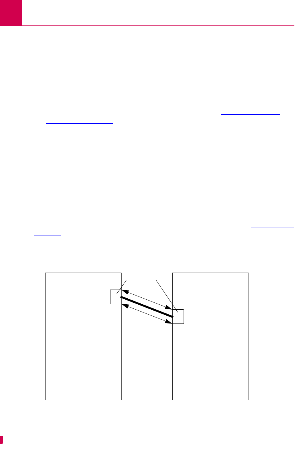
AI296 Version 9.8x User’s Guide
IP Over X.25 Subnet Configuration: Configuration Overview
5-2
Configuration Overview
AI296 supports encapsulation of the IP protocol over X.25 (IXE) networks. The local
AI296 wraps IP packets (either control or data packets) inside of X.25 frames and
sends them across the X.25 network. The remote AI296 receives the X.25 frames and
unwraps the IP packets.
To allow IP traffic to run over an X.25 network, the network must be configured to
support IP over X.25 encapsulation. To do this, complete the following tasks:
zConfigure and verify the X.25 SVC links. Refer to section SVC Configuration
Settings on page 6-90 for information about configuring X.25 SVC links.
zCreate IP subnets and IP over X.25 remote pairs.
zCreate IP static routing table entries (optional).
zReset AI296.
Before Configuration
In order for the TCP/IP stack to know where to route incoming packets, an appropriate
subnet must be configured. IP addresses and subnets must be assigned to the local
and remote sides of the X.25 link (also called "doorway"). X.121 addresses are then
assigned to the local and remote sides. After this, a static route can be setup through
the IXE link to the remote doorway IP address. Refer to the example in Figure 5-1 on
page 5-2 for an illustration of how to configure IP over X.25.
Figure 5-1 IXE Example
IP Tunnel
within X.25
11
8
Local AI296 Remote AI296
IP address: 198.127.1.196 IP address: 198.30.2.196
Local IXE doorway
address: 20.0.0.1
Local IXE doorway
X.121 address:
3035550005
Subnet mask: 255.255.255.0 Subnet mask: 255.255.255.0
IXE subnet mask:
255.255.255.0
Remote IXE doorway
address: 20.0.0.2
Remote IXE doorway
X.121 address:
6065550008
IXE subnet mask:
255.255.255.0
Link Numbers

AI296 Version 9.8x User’s Guide
IP Over X.25 Subnet Configuration: Local Settings
5-3
Local Settings
IXE can be configured using either one local and one remote AI296 or one local AI296
and a router that supports IP over X.25. The following configuration components are
available:
zLocal IP Address for this Subnet
zLocal IP Subnet Mask
zLocal X.25 Link Number
Local IP Address for this Subnet
Description
This menu item configures the local IXE doorway address for the subnet.
Note: This address is not the same as the local AI296 IP address.
Menu Item Type
Data
Configuration in the AI198 Menu System
1. Access Menu 4.2.11.13. This menu displays a list of all the configured IP over
X.25 subnets.
2. From Menu 4.2.11.13, enter a value (02 through 11) associated with the IP over
X.25 subnet to be configured. Menu 4.2.11.13.1 appears.
3. For 01 Local IP address for this subnet, enter the subnet IP address value. The
default is 0.0.0.0.
This example displays 01 Local IP address for this subnet set to 24.35.132.67.
Configuration in the AI296 Local Menu System
1. Access the IP Over X.25 Subnet Menu.
2. From the IP Over X.25 Subnet Menu, select Add. The IP Over X.25 Subnet Edit
Menu appears.
3. For Local IP Address for this Subnet, enter the subnet IP address value.
>1,24.35.132.67
Menu 4.2.11.13.1
01 Local IP address for this subnet-----------------------------024.035.132.067

AI296 Version 9.8x User’s Guide
IP Over X.25 Subnet Configuration: Local Settings
5-4
This example displays Local IP Address for this Subnet set to 24.35.132.67.
Local IP Subnet Mask
Description
This menu item configures the local IXE doorway IP subnet mask.
Menu Item Type
Data
Configuration in the AI198 Menu System
1. Access Menu 4.2.11.13. This menu displays a list of all the configured IP over
X.25 subnets.
2. From Menu 4.2.11.13, enter a value (02 through 11) associated with the IP over
X.25 subnet to be configured. Menu 4.2.11.13.1 appears.
3. For 02 Local IP Mask for this subnet, enter the subnet IP subnet mask value. The
default is 255.255.255.252.
This example displays 02 Local IP Mask for this subnet set to 255.255.0.0.
Configuration in the AI296 Local Menu System
1. Access the IP Over X.25 Subnet Menu.
2. From the IP Over X.25 Subnet Menu, select Add. The IP Over X.25 Subnet Edit
Menu appears.
3. For Local IP Mask for this Subnet, enter the subnet IP subnet mask value. The
default is 255.255.255.252.
This example displays Local IP Mask for this Subnet set to 255.255.0.0.
IP Over X.25 Subnet Edit Menu
Local IP Address for this Subnet . . . . . . . . . .......... 24.35.132.67
>2,255.255.0.0
Menu 4.2.11.13.1
01 Local IP address for this subnet-----------------------------024.035.132.067
02 Local IP Mask for this subnet--------------------------------255.255.000.000
IP Over X.25 Subnet Edit Menu
Local IP Address for this Subnet . . . . . . . . . ............... 0.0.0.0
Local IP Mask for this Subnet . . . . . . . . . . . ........... 255.255.0.0

AI296 Version 9.8x User’s Guide
IP Over X.25 Subnet Configuration: Local Settings
5-5
Local X.25 Link Number
Description
This menu item configures the local IXE doorway link number.
Menu Item Type
Data
Configuration in the AI198 Menu System
1. Access Menu 4.2.11.13. This menu displays a list of all the configured IP over
X.25 subnets.
2. From Menu 4.2.11.13, enter a value (02 through 11) associated with the IP over
X.25 subnet to be configured. Menu 4.2.11.13.1 appears.
3. For 03 Local X.25 link number, enter 3, and the link number. Valid values are 1 to
16. The default is 1.
This example displays 03 Local X.25 link number set to 12.
Configuration in the AI296 Local Menu System
1. Access the IP Over X.25 Subnet Menu.
2. From the IP Over X.25 Subnet Menu, select Add. The IP Over X.25 Subnet Edit
Menu appears.
3. For Local X.25 link number, enter the link number. The default is 1.
This example displays Local X.25 link number set to 12.
>3,12
Menu 4.2.11.13.1
01 Local IP address for this subnet-----------------------------024.035.132.067
02 Local IP Mask for this subnet--------------------------------255.255.000.000
03 Local X.25 link number----------------------------------------------------12
IP Over X.25 Subnet Edit Menu
Local IP Address for this Subnet . . . . . . . . . ............... 0.0.0.0
Local IP Mask for this Subnet . . . . . . . . . . . ....... 255.255.255.252
Local X.25 link number . . . . . . . . . . . . . . . . . . . . .12

AI296 Version 9.8x User’s Guide
IP Over X.25 Subnet Configuration: Remote Settings
5-6
Remote Settings
IXE can be configured using either one local and one remote AI296 or one local AI296
and a router that supports IP over X.25. The following configuration components are
available:
zRemote IP Address for this Subnet
zRemote X.121 Address
Remote IP Address for this Subnet
Description
This menu item configures the remote IXE IP address for the subnet.
Note: This address is not the same as the remote AI296 (or router) IP address.
Menu Item Type
Data
Configuration in the AI198 Menu System
1. Access Menu 4.2.11.13. This menu displays a list of all the configured IP over
X.25 subnets.
2. From Menu 4.2.11.13, enter a value (02 through 11) associated with the IP over
X.25 subnet to be configured. Menu 4.2.11.13.1 appears.
3. For 04 Remote IP address for this subnet, enter the remote IP address value. The
default is 0.0.0.0.
This example displays 04 Remote IP address for this subnet set to 36.82.234.54.
Configuration in the AI296 Local Menu System
1. Access the IP Over X.25 Subnet Menu.
2. From the IP Over X.25 Subnet Menu, select Add. The IP Over X.25 Subnet Edit
Menu appears.
3. For Remote IP Address for this Subnet, enter the remote IP address value. The
default is 0.0.0.0.
>4,36.82.234.54
Menu 4.2.11.13.1
01 Local IP address for this subnet-----------------------------000.000.000.000
02 Local IP Mask for this subnet--------------------------------255.255.255.252
03 Local X.25 link number----------------------------------------------------01
04 Remote IP address for this subnet----------------------------036.082.234.054

AI296 Version 9.8x User’s Guide
IP Over X.25 Subnet Configuration: Remote Settings
5-7
This example displays Remote IP Address for this Subnet set to 93.67.158.56.
Remote X.121 Address
Description
This menu item configures the IXE remote X.121 address. Each IXE connection must
have a unique local/remote X.121 address pair. This means there cannot be two
separate IXE connections in the same AI296 with the same local X.121 address and
the same remote X.121 address.
Note: X.121 addresses are assigned per link on AI296, not per SVC.
Menu Item Type
Data
Configuration in the AI198 Menu System
1. Access Menu 4.2.11.13. This menu displays a list of all the configured IP over
X.25 subnets.
2. From Menu 4.2.11.13, enter a value (02 through 11) associated with the IP over
X.25 subnet to be configure. Menu 4.2.11.13.1 appears.
3. For 05 Remote X121 address, enter 5, and the remote address value. Maximum
length is 15 characters.
This example displays 05 Remote X121 address set to 6505550043.
IP Over X.25 Subnet Edit Menu
Local IP Address for this Subnet . . . . . . . . . ............... 0.0.0.0
Local IP Mask for this Subnet . . . . . . . . . . . ....... 255.255.255.252
Local X.25 link number . . . . . . . . . . . . . . . . . . . . . 0
Remote IP Address for this Subnet . . . . . . . . . .......... 93.67.158.56
>5,6505550043
Menu 4.2.11.13.1
01 Local IP address for this subnet-----------------------------000.000.000.000
02 Local IP Mask for this subnet--------------------------------255.255.255.252
03 Local X.25 link number----------------------------------------------------01
04 Remote IP address for this subnet----------------------------036.082.234.054
05 Remote X121 address------------------------------------------ 6505550043

AI296 Version 9.8x User’s Guide
IP Over X.25 Subnet Configuration: Remote Settings
5-8
Configuration in the AI296 Local Menu System
1. Access the IP Over X.25 Subnet Menu.
2. From the IP Over X.25 Subnet Menu, select Add. The IP Over X.25 Subnet Edit
Menu appears.
3. For Remote X121 Address, enter the remote address value.
This example displays Remote X121 Address set to 6505550043.
IP Over X.25 Subnet Edit Menu
Local IP Address for this Subnet . . . . . . . . . ............... 0.0.0.0
Local IP Mask for this Subnet . . . . . . . . . . . ....... 255.255.255.252
Local X.25 link number . . . . . . . . . . . . . . . . . . . . . 0
Remote IP Address for this Subnet . . . . . . . . . .......... 93.67.158.56
Remote X121 Address . . . . . . . . . . . . . . . . ........ 6505550043

6-1
6
Link Configuration
This chapter provides information on configuring AI296 links in the AI198 and AI296 local menu
systems.
Guide to this Chapter
AI296 Link Types
BX.25 Configuration
Connect Options Configuration
Disconnect Options Configuration
General Link Properties Configuration
General PPP Properties Configuration
LAPB Parameters Configuration
Modem Option Configuration
PPP Authentication Configuration
Quick X.25 Configuration
RTS/DTR Lead Control Configuration
X.25 Parameters Configuration
Virtual Circuit Configuration

AI296 Version 9.8x User’s Guide
Link Configuration: AI296 Link Types
6-2
AI296 Link Types
AI296 has six configurable link types:
zAsynchronous
zAsynchronous PPP
zHDLC-Bridge
zMLT
zSynchronous PPP
zX.25
Asynchronous
Asynchronous links use asynchronous transmission and support multiple baud rates,
parity types, stop bits, and software flow or hardware control.
See Also
zConnect Options Configuration
zDisconnect Options Configuration
zGeneral Link Properties Configuration
zModem Option Configuration
zRTS/DTR Lead Control Configuration
Asynchronous PPP
Asynchronous PPP links use PPP (point-to-point protocol) and asynchronous
transmission. They support PAP and CHAP for authentication and can be set as
bridged (BCP) or routed (IPCP) interfaces.
See Also
zConnect Options Configuration
zDisconnect Options Configuration
zGeneral Link Properties Configuration
zGeneral PPP Properties Configuration
zModem Option Configuration
zPPP Authentication Configuration
zRTS/DTR Lead Control Configuration

AI296 Version 9.8x User’s Guide
Link Configuration: AI296 Link Types
6-3
HDLC-Bridge
HDLC-Bridge links run with an HDLC link layer protocol in Asynchronous Balanced
Mode and bridge Ethernet frames. HDLC-Bridge links can provide clocking or
synchronize with an external clock.
See Also
General Link Properties Configuration
MLT
MLT links are designed for interfacing with the metallic loop testing switch application
found in telephone switch networks. This application consists of proprietary messages
transported using LAPB. The MLT link type enables the transporting of proprietary
messages across an IP network. LAPB is terminated on AI296 and the data is
transported to a remote end point using another transport protocol, such as TCP/IP.
See Also
zGeneral Link Properties Configuration
zLAPB Parameters Configuration
zGeneral PPP Properties Configuration
zPPP Authentication Configuration
Synchronous PPP
Synchronous PPP links use PPP (point-to-point protocol) and synchronized
transmission. They can provide clocking or synchronize with an external clock.
Synchronous PPP links support PAP and CHAP for authentication and can be set as
bridged (BCP) or routed (IPCP) interfaces.
See Also
zGeneral Link Properties Configuration
zGeneral PPP Properties Configuration
zPPP Authentication Configuration

AI296 Version 9.8x User’s Guide
Link Configuration: AI296 Link Types
6-4
X.25
X.25 links provide a synchronous connection to a packet-switched X.25 network. X.25
links can behave as DTE or DCE and can provide clocking or synchronize with an
external clock. X.25 links support both PVC and SVC calls and allow configuration of
a variety of LAPB and X.25 protocol settings.
See Also
zBX.25 Configuration
zGeneral Link Properties Configuration
zLAPB Parameters Configuration
zQuick X.25 Configuration
zX.25 Parameters Configuration

AI296 Version 9.8x User’s Guide
Link Configuration: BX.25 Configuration
6-5
BX.25 Configuration
AI296 is BX.25 compatible and implements passive links. Passive links are not a part
of the BX.25 protocol. Once a passive link is active, it uses the BX.25 protocol.
Notes: BX.25 is supported on only one link per AI296.
Some BX.25 parameters may vary based on the AI296 installation.
The following configuration components are available:
zBX.25 Configuration Values Usage
zBX.25 Modulo
zBX.25 Support
zBX.25 Timer Settings
BX.25 Configuration Values Usage
Description
This menu item enables or disables the use of the values configured in the BX.25
menu.
Menu Item Type
Toggle
Link Type Availability
X.25
Configuration in the AI198 Menu System
1. Access Menu 4.2.11.12.11.
2. For 02*Use these configuration values, enter 2 to select Enabled or Disabled. The
default is Enabled.
This example displays 02*Use these configuration values set to Enabled.
>2
Menu 4.2.11.12.11
01*BX25 Support (Enabled, Disabled)------------------------------------ Enabled
02*Use these configuration values (Enabled, Disabled)------------------ Enabled

AI296 Version 9.8x User’s Guide
Link Configuration: BX.25 Configuration
6-6
Configuration in the AI296 Local Menu System
1. Access the X.25 Link Menu.
2. Select BX.25 Menu. The BX.25 Menu appears.
3. For Use BX.25 Configuration Values, select Enabled or Disabled. The default is
Enabled.
This example displays Use BX.25 Configuration Values set to Enabled.
BX.25 Modulo
Description
This menu item defines a modulo value. A modulo is used by the BX.25 protocol to
define the value at which the packet sequence numbers will rollover.
Menu Item Type
Data
Link Type Availability
X.25
Configuration in the AI198 Menu System
1. Access Menu 4.2.11.12.11.
2. For 04 Modulo, enter 4, and the desired value. The default is 256.
This example displays 04 Modulo set to 200.
BX.25 Menu
Link being configured . . . . . . . . . . . . . . . . . . . . . . . . . 03
BX.25 Support . . . . . . . . . . . . . . . . . . . . [Enabled] Disabled
Use BX.25 Configuration Values. . . . . . . . . . . . [Enabled] Disabled
>4,200
Menu 4.2.11.12.11
01*BX25 Support (Enabled, Disabled)------------------------------------Disabled
02*Use these configuration values (Enabled, Disabled)------------------ Enabled
03 Sending Unit Number (0 - 9)------------------------------------------------0
04 Modulo (5 - 256)---------------------------------------------------------200

AI296 Version 9.8x User’s Guide
Link Configuration: BX.25 Configuration
6-7
Configuration in the AI296 Local Menu System
1. Access the X.25 Link Menu.
2. Select BX.25 Menu. The BX.25 Menu appears.
3. For BX.25 Modulo, enter the desired value. The default is 256.
This example displays BX.25 Modulo set to 150.
BX.25 Support
Description
This menu item enables or disables BX.25 module support on a link. BX.25 support
can only be enabled on one link at a time. When enabling BX.25 support, first disable
support on all other links.
Menu Item Type
Toggle
Link Type Availability
X.25
Configuration in the AI198 Menu System
1. Access Menu 4.2.11.12.11.
2. For 01*BX25 Support, enter 1 to select Enabled or Disabled. The default is Disabled.
This example displays 01*BX25 Support set to Enabled.
BX.25 Menu
Link being configured . . . . . . . . . . . . . . . . . . . . . . . . . 03
BX.25 Support . . . . . . . . . . . . . . . . . . . . Enabled [Disabled]
Use BX.25 Configuration Values. . . . . . . . . . . . [Enabled] Disabled
Sending Unit Number . . . . . . . . . . . . . . . . . . . . . . . . . . . . .4
BX.25 Modulo. . . . . . . . . . . . . . . . . . . . . . . . . . . . . . . .150
>1
Menu 4.2.11.12.11
01*BX25 Support (Enabled, Disabled)------------------------------------ Enabled

AI296 Version 9.8x User’s Guide
Link Configuration: BX.25 Configuration
6-8
Configuration in the AI296 Local Menu System
1. Access the X.25 Link Menu.
2. Select BX.25 Menu. The BX.25 Menu appears.
3. For BX.25 Support, select Enabled or Disabled. The default is Disabled.
This example displays BX.25 Support set to Enabled.
BX.25 Timer Settings
Description
The initial BX.25 timer settings are configured using two menu items:
zConnect timer ST2—Defines the maximum number of seconds that the BX.25
protocol will wait for a response to a session connect request.
zSend timer ST3—Defines the data acknowledge timer, which gives the maximum
number of seconds that the BX.25 protocol will wait for an acknowledgement to a
Data Request.
Menu Item Type
Data
Link Type Availability
X.25
Configuration in the AI198 Menu System
1. Access Menu 4.2.11.12.11.
2. For 05 Connect Timer ST2, enter 5, and the connect timer value. Valid values are 0
to 65535. The default is 12.
3. For 06 Send Timer ST3, enter 6, and the send timer value. Valid values are 0 to
65535. The default is 18.
BX.25 Menu
Link being configured . . . . . . . . . . . . . . . . . . . . . . . . . 03
BX.25 Support . . . . . . . . . . . . . . . . . . . . [Enabled] Disabled

AI296 Version 9.8x User’s Guide
Link Configuration: BX.25 Configuration
6-9
This example displays 05 Connect Timer ST2 set to 33 and 06 Send Timer ST3 set to 45.
Configuration in the AI296 Local Menu System
1. Access the X.25 Link Menu.
2. From the X.25 Link Menu, select the BX.25 Menu.
3. For Connect Timer ST2, enter the connect timer value. The default is 12.
4. For Send Timer ST3, enter the send timer value. The default is 18.
This example displays Connect Timer ST2 set to 225 and Send Timer ST3 set to 275.
>6,35
Menu 4.2.11.12.11
01*BX25 Support (Enabled, Disabled)------------------------------------ Enabled
02*Use these configuration values (Enabled, Disabled)------------------ Enabled
03 Sending Unit Number (0 - 9)------------------------------------------------2
04 Modulo (5 - 256)---------------------------------------------------------122
05 Connect Timer ST2 (seconds)--------------------------------------------00033
06 Send Timer ST3 (seconds)-----------------------------------------------00045
BX.25 Menu
Link being configured . . . . . . . . . . . . . . . . . . . . . . . . . 03
BX.25 Support . . . . . . . . . . . . . . . . . . . . [Enabled] Disabled
Use BX.25 Configuration Values. . . . . . . . . . . . [Enabled] Disabled
Sending Unit Number . . . . . . . . . . . . . . . . . . . . . . . . . . . . .5
BX.25 Modulo. . . . . . . . . . . . . . . . . . . . . . . . . . . . . . . .200
Connect Timer ST2 (seconds) . . . . . . . . . . . . . . . . . . . . . . .. 225
Send Timer ST3 (seconds). . . . . . . . . . . . . . . . . . . . . . . . .. 275

AI296 Version 9.8x User’s Guide
Link Configuration: Connect Options Configuration
6-10
Connect Options Configuration
Connect options configure the AI296 connection parameters. These options are
available for asynchronous links and asynchronous PPP links. The following
configuration items are available:
zAlias
zCall Retry Interval
zConnect String
zConnection Settings
zLink Application
Alias
Description
This menu item specifies an alias name for the connection. When the link connection
options are satisfied, a call is placed based on information contained in the alias
name.
The specified name must correspond to an alias that has been created in the Alias
Menu. If no alias name is specified and Link Application is set to ALIAS in the AI198
menu system (AppAlias in the AI296 local menu system), then a default alias is used.
The default alias is the concatenation of the string asy. with the numeric link number,
such as asy.3, which indicates link number 3.
Note: The 02 Alias menu item is used only if 01*Link Application is set to ALIAS
(AppAlias in the AI296 local menu system).
Menu Item Type
Data
Link Type Availability
Async
Configuration in the AI198 Menu System
1. Access Menu 4.2.11.12.11.
2. For 02 Alias, enter 2, and the alias name.

AI296 Version 9.8x User’s Guide
Link Configuration: Connect Options Configuration
6-11
This example displays 02 Alias set to async.4.1.
Configuration in the AI296 Local Menu System
1. Access the Async Link Menu.
2. Select Connect Options Menu. The Connect Options Menu appears.
3. For Link Application Alias, enter the alias value.
This example displays Link Application Alias set to async.4.1.
Call Retry Interval
Description
This menu item defines a value for the call retry interval. If a call fails to connect and
the retry interval is greater than 0, the link attempts to place the call again after the
specified number of seconds elapse. This setting has no effect on calls placed to the
link when the link is the destination and not the call originator. A value of 0 disables
call retry interval functionality.
Menu Item Type
Data
Link Type Availability
Async
Configuration in the AI198 Menu System
1. Access Menu 4.2.11.12.11.
2. For 03 Call retry interval, enter 3, and the interval value. The default is 0.
>2,async.4.1
Menu 4.2.11.12.11
01*Link Application (Login, Destination, Alias)---------------------------ALIAS
02 Alias--------------------------------------------------------------async.4.1
Connect Options Menu
Link being configured . . . . . . . . . . . . . . . . . . . . . . . . . 1
Link Application . . . . . . . . . . . . Login Destination [AppAlias]
Link Application Alias . . . . . . ................................. async.4.1

AI296 Version 9.8x User’s Guide
Link Configuration: Connect Options Configuration
6-12
This example displays 03 Call retry interval set to 134.
Configuration in the AI296 Local Menu System
1. Access the Async Link Menu.
2. Select Connect Options Menu. The Connect Options Menu appears.
3. For Call Retry Interval, enter the desired interval value. The default is 0.
This example displays Call Retry Interval set to 134.
Connect String
Description
This menu item configures the string that is sent after a connection is established. The
following character values apply:
z<b> sends a break signal.
z<
n
> represents the decimal value of an ASCII character. Valid values are 0 to 255.
z
text
represents the text value in the string.
z<p
#
> represents a pause control sequence.
#
is the number of tenths of seconds
to pause. Valid values are 1 to 20 (for 0.1 seconds to 2 seconds).
For example, string <b>login<13><p 10><b> sends:
zA break signal
zText “login”
zA carriage return
zA 1 second pause
zAnother break signal.
>3,134
Menu 4.2.11.12.11
01*Link Application (Login, Destination, Alias)---------------------------ALIAS
02 Alias--------------------------------------------------------------async.4.1
03 Call retry interval (0 - 32767 s, 0 = disabled)------------------------00134
Connect Options Menu
Link being configured . . . . . . . . . . . . . . . . . . . . . . . . . 1
Link Application . . . . . . . . . . . . Login Destination [AppAlias]
Link Application Alias . . . . . . ................................. async.4.1
Call Retry Interval (0 - 32767s, 0 = disable) . . . . . . . . . . . . . .. 134

AI296 Version 9.8x User’s Guide
Link Configuration: Connect Options Configuration
6-13
Menu Item Type
Data
Link Type Availability
Async
Configuration in the AI198 Menu System
1. Access Menu 4.2.11.12.11.
2. For 08 Connect string, enter 8, and the connect string.
This example displays 08 Connect string set to <b>newstring<33><p 13><b>.
Configuration in the AI296 Local Menu System
1. Access the Async Link Menu.
2. Select Connect Options Menu. The Connect Options Menu appears.
3. For Connect String, enter the connect string.
This example displays Connect String set to <b>newstring<33><p 13><b>.
>8,<b>newstring<33><p 13><b>
Menu 4.2.11.12.11
01*Link Application (Login, Destination, Alias)---------------------------ALIAS
02 Alias--------------------------------------------------------------async.4.1
03 Call retry interval (0 - 32767 s, 0 = disabled)------------------------00134
04 Dial/Connect when DSR is on----------------------------------------------N/A
05*Connect when DCD is on---------------------------------------------------OFF
06*Connect when characters are received------------------------------------- ON
07*Connect without DSR, DCD or received characters--------------------------OFF
08 Connect string-------------------------------------<b>newstring<33><p 13><b>
Connect Options Menu
Link being configured . . . . . . . . . . . . . . . . . . . . . . . . . 1
Link Application . . . . . . . . . . . . Login Destination [AppAlias]
Link Application Alias . . . . . . ................................. async.4.1
Call Retry Interval (0 - 32767s, 0 = disable) . . . . . . . . . . . . . .. 134
Dial/Connect when DSR is on . . . . . . . . . . . . . . . . . . On [Off]
Connect when DCD is on. . . . . . . . . . . . . . . . . . . . . [On] Off
Connect when characters are received. . . . . . . . . . . . . . On [Off]
Connect without DSR, DCD or received characters . . . . . . . . On [Off]
Connect String . . . . . . . . . . . ............... <b>newstring<33><p 13><b>

AI296 Version 9.8x User’s Guide
Link Configuration: Connect Options Configuration
6-14
Connection Settings
Description
The connection settings are configured using three menu items:
zConnect when DCD is on—Enables or disables link connection when DCD is
asserted. If Connect when characters are received is also enabled and is satisfied
first, then Connect when DCD is on has no effect on the link connection.
zConnect when characters are received—Enables or disables the link connection
when incoming characters are received. If Connect when DCD is on is also enabled
and is satisfied first, then Connect when characters are received has no effect on the
link connection.
zConnect without DSR, DCD or received characters—When this menu item is enabled,
Connect when DCD is on and Connect when characters are received are forced off and
the retry interval is set to 30. If the link application type is set to LOGIN or ALIAS,
connection will occur as soon as the link is enabled (completely independent from
the DCD and incoming character status). If the link application type is set to
DESTINATION, the link will connect immediately when an outgoing call is placed to
the destination (also completely independent from DCD and incoming character
status).
Note: Dial/Connect when DSR is on has no effect on AI296 operation.
Menu Item Type
Toggle
Link Type Availability
Async
Configuration in the AI198 Menu System
1. Access Menu 4.2.11.12.11.
2. For 05*Connect when DCD is on, enter 5 to select ON or OFF. The default is OFF.
3. For 06*Connect when characters are received, enter 6 to select ON or OFF. The default
is ON.
4. For 07*Connect without DSR, DCD or received characters, enter 7 to select ON or OFF.
The default is OFF.

AI296 Version 9.8x User’s Guide
Link Configuration: Connect Options Configuration
6-15
This example displays:
z05*Connect when DCD is on set to ON
z06*Connect when characters are received set to OFF
z07*Connect without DSR, DCD or received characters set to OFF.
Configuration in the AI296 Local Menu System
1. Access the Async Link Menu.
2. Select Connect Options Menu. The Connect Options Menu appears.
3. For Connect when DCD is on, select ON or OFF. The default is OFF.
4. For Connect when characters are received, select ON or OFF. The default is ON.
5. For Connect without DSR, DCD or received characters, select ON or OFF. The default is
OFF.
This example displays:
zConnect when DCD is on set to On
zConnect when characters are received set to Off
zConnect without DSR, DCD or received characters set to Off.
>5
Menu 4.2.11.12.11
01*Link Application (Login, Destination, Alias)---------------------------ALIAS
02 Alias--------------------------------------------------------------async.4.1
03 Call retry interval (0 - 32767 s, 0 = disabled)------------------------00030
04 Dial/Connect when DSR is on----------------------------------------------N/A
05*Connect when DCD is on--------------------------------------------------- ON
06*Connect when characters are received-------------------------------------OFF
07*Connect without DSR, DCD or received characters--------------------------OFF
Connect Options Menu
Link being configured . . . . . . . . . . . . . . . . . . . . . . . . . 1
Link Application . . . . . . . . . . . . Login Destination [AppAlias]
Link Application Alias . . . . . . ................................. async.4.1
Call Retry Interval (0 - 32767s, 0 = disable) . . . . . . . . . . . . . .. 134
Dial/Connect when DSR is on . . . . . . . . . . . . . . . . . . On [Off]
Connect when DCD is on. . . . . . . . . . . . . . . . . . . . . [On] Off
Connect when characters are received. . . . . . . . . . . . . . On [Off]
Connect without DSR, DCD or received characters . . . . . . . . On [Off]

AI296 Version 9.8x User’s Guide
Link Configuration: Connect Options Configuration
6-16
Link Application
Description
This menu item configures the link application type. The following options are
available:
zLogin—Specifies that the link will prompt for a user name and password when
connected. Upon successful login, a menu appears showing the available
destination alias names.
zDestination—Specifies that the link does not accept incoming calls. The link must
be accessed internally using alias lookup from another link or from a TCP/IP
connection.
zAlias (AppAlias)—Specifies that the link will attempt to place a call using direct
alias lookup without displaying a destination menu. If the link has a link application
alias name configured, then that name is used. Otherwise, a default alias name
(ASY.
linkNum
) is used.
Menu Item Type
Toggle
Link Type Availability
Async
Configuration in the AI198 Menu System
1. Access Menu 4.2.11.12.11.
2. For 01*Link Application, enter 1 to select LOGIN, DESTINATION, or ALIAS. The default is
LOGIN.
This example displays 01*Link Application set to DESTINATION.
>1
Menu 4.2.11.12.11
01*Link Application (Login, Destination, Alias)---------------------DESTINATION

AI296 Version 9.8x User’s Guide
Link Configuration: Connect Options Configuration
6-17
Configuration in the AI296 Local Menu System
1. Access the Async Link Menu.
2. Select Connect Options Menu. The Connect Options Menu appears.
3. For Link Application, select Login, Destination, or AppAlias. The default is Login.
This example displays Link Application set to Destination.
Connect Options Menu
Link being configured . . . . . . . . . . . . . . . . . . . . . . . . . 1
Link Application . . . . . . . . . . . . Login [Destination] AppAlias

AI296 Version 9.8x User’s Guide
Link Configuration: Disconnect Options Configuration
6-18
Disconnect Options Configuration
Disconnect options configure the parameters that are used when AI296 disconnects.
These options are available for asynchronous and asynchronous PPP links. The
following configuration items are available:
zDisconnect Inactivity Timer Settings
zDisconnect Settings
zDisconnect String
Disconnect Inactivity Timer Settings
Description
The disconnect inactivity timer settings are configured using three menu items:
zDisconnect inactivity timer—Defines an inactivity timer value. This value
establishes a timeout interval after which the link will automatically disconnect if
no data has been sent or received for the specified number of seconds. This value
only applies to incoming calls on links that have a retry interval timer setting of 0
and a link application setting of LOGIN or ALIAS (AppAlias).
Note: The Disconnect inactivity timer option must be set to a value greater than
0 for the inactivity timer to function.
zInactivity timer enabled when link receives call—Enables or disables the
disconnect inactivity timer when the link receives a call.
zInactivity timer resets on incoming characters from destination—When enabled,
incoming characters count as activity on a link (the inactivity timer resets). When
disabled, they do not count (the inactivity timer does not reset).
Menu Item Type
Data for disconnect inactivity timer
Toggle for Inactivity timer enabled when link receives call and Inactivity timer resets
on incoming characters from destination
Link Type Availability
Async
Configuration in the AI198 Menu System
1. Access Menu 4.2.11.12.12.
2. For 04 Disconnect inactivity timer, enter 4, and the timer value. The default is 0.

AI296 Version 9.8x User’s Guide
Link Configuration: Disconnect Options Configuration
6-19
3. For 05*Inactivity Timer enabled when link receives call, enter 5 to select ON or OFF.
The default is OFF.
4. For 06*Inactivity Timer resets on incoming characters from destination, enter 6 to
select ON or OFF. The default is ON.
This example displays:
z04 Disconnect inactivity timer set to 236
z05*Inactivity Timer enabled when link receives call set to ON
z06*Inactivity Timer resets on incoming characters from destination set to OFF.
Configuration in the AI296 Local Menu System
1. Access the Async Link Menu.
2. Select Disconnect Options Menu. The Disconnect Options Menu appears.
3. For Disconnect inactivity timer, enter the timer value. The default is 0.
4. For Inactivity Timer enabled when link receives call, select On or Off. The default
is Off.
5. For Inactivity Timer resets on incoming characters from destination, select On or
Off. The default is On.
This example displays:
zDisconnect inactivity timer set to 367.
zInactivity Timer enabled when link receives call set to On.
zInactivity Timer resets on incoming characters from destination set to Off.
>12
Menu 4.2.11.12.12
01 Disconnect when DSR off--------------------------------------------------N/A
02*Disconnect when DCD off--------------------------------------------------OFF
03*Disconnect when a break character is received---------------------------- ON
04 Disconnect inactivity timer (0 - 32767 s, 0 = disabled)----------------00236
05*Inactivity Timer enabled when link receives call------------------------- ON
06*Inactivity Timer resets on incoming characters from destination----------OFF
Disconnect Options Menu
Link being configured . . . . . . . . . . . . . . . . . . . . . . . . . 3
Disconnect when DCD is off . . . . . . . . . . . . . . . . . . . On [Off]
Disconnect when a Break character is received . . . . . . . . . [On] Off
Disconnect inactivity timer (0 - 32767s, 0 = disabled) . . . . . . . . . .. 367
Inactivity Timer enabled when link receives call . . . . . . . . [On] Off
Inactivity Timer resets on incoming characters from destination On [Off]

AI296 Version 9.8x User’s Guide
Link Configuration: Disconnect Options Configuration
6-20
Disconnect Settings
Description
The disconnect settings are configured using two menu items:
zDisconnect when a break character is received—Enables or disables link
disconnection when a break character is received.
zDisconnect when DCD off—Enables or disables link disconnection when DCD is not
asserted.
Note: AI296 does not consider the DSR state when disconnecting calls.
Menu Item Type
Toggle
Link Type Availability
Both menu items are available for async links
Menu item Disconnect when DCD off is available for asyncPPP links
Configuration in the AI198 Menu System
1. Access Menu 4.2.11.12.12.
2. For 02*Disconnect when DCD off, enter 2 to select ON or OFF. The default is OFF.
3. For 03*Disconnect when a break character is received, enter 3 to select ON or OFF.
The default is ON.
This example displays 02*Disconnect when DCD off set to ON and 03*Disconnect when a
break character is received set to OFF.
Configuration in the AI296 Local Menu System
1. Access the Async Link Menu.
2. Select Disconnect Options Menu. The Disconnect Options Menu appears.
3. For Disconnect when DCD is off, select On or Off. The default is Off.
4. For Disconnect when a Break character is received, select On or Off. The default is
On.
>3
Menu 4.2.11.12.12
01 Disconnect when DSR off--------------------------------------------------N/A
02*Disconnect when DCD off-------------------------------------------------- ON
03*Disconnect when a break character is received----------------------------OFF

AI296 Version 9.8x User’s Guide
Link Configuration: Disconnect Options Configuration
6-21
This example displays Disconnect when DCD is off set to On and Disconnect when a Break
character is received set to Off for an async link.
Disconnect String
Description
This menu item configures the string the link sends before the link disconnects. The
following character values apply:
z<b> sends a break signal.
z<
n
> represents the decimal value of an ASCII character. Valid values are 0 to 255.
z
text
represents the text value in the string.
z<p
#
> represents a pause control sequence.
#
is the number of tenths of seconds
to pause. Valid values are 1 to 20 (for 0.1 seconds to 2 seconds).
For example, string <b>login<13><p 10><b> sends:
zA break signal
zThe text “login”
zA carriage return
zA one second pause
zAnother break signal.
Menu Item Type
Data
Link Type Availability
Async
Configuration in the AI198 Menu System
1. Access Menu 4.2.11.12.12.
2. For 07 Disconnect string, enter 7, and the disconnect string. Maximum length is
80 characters.
Disconnect Options Menu
Link being configured . . . . . . . . . . . . . . . . . . . . . . . . . 4
Disconnect when DCD is off . . . . . . . . . . . . . . . . . . . [On] Off
Disconnect when a Break character is received . . . . . . . . . On [Off]

AI296 Version 9.8x User’s Guide
Link Configuration: Disconnect Options Configuration
6-22
This example displays 07 Disconnect string set to <b>newString<33><p 15><b>.
Configuration in the AI296 Local Menu System
1. Access the Async Link Menu.
2. Select Disconnect Options Menu. The Disconnect Options Menu appears.
3. For Disconnect String, enter the disconnect string.
This example displays Disconnect String set to <b>newString<33><p 15><b>.
>7,<b>newString<33><p 15><b>
Menu 4.2.11.12.12
01 Disconnect when DSR off--------------------------------------------------N/A
02*Disconnect when DCD off-------------------------------------------------- ON
03*Disconnect when a break character is received----------------------------OFF
04 Disconnect inactivity timer (0 - 32767 s, 0 = disabled)----------------00000
05*Inactivity Timer enabled when link receives call-------------------------OFF
06*Inactivity Timer resets on incoming characters from destination---------- ON
07 Disconnect string----------------------------------<b>newString<33><p 15><b>
Disconnect Options Menu
Link being configured . . . . . . . . . . . . . . . . . . . . . . . . . 3
Disconnect when DCD is off . . . . . . . . . . . . . . . . . . . [On] Off
Disconnect when a Break character is received . . . . . . . . . On [Off]
Disconnect inactivity timer (0 - 32767s, 0 = disabled) . . . . . . . . . .. 367
Inactivity Timer enabled when link receives call . . . . . . . . [On] Off
Inactivity Timer resets on incoming characters from destination On [Off]
Disconnect String . . . . . . . . . . .............. <b>newString<33><p 15><b>

AI296 Version 9.8x User’s Guide
Link Configuration: General Link Properties Configuration
6-23
General Link Properties Configuration
General link properties are configurable using menus accessed directly from the link
configuration menu. The following configuration items are available:
Auto Disable Error Limit
Description
This menu item disables a link when the rate of errors received on that link exceeds a
user-specified threshold. This prevents a bad link or cable from streaming enough
errors to lock up or crash AI296.
Menu Item Type
Data
Link Type Availability
Async, AsyncPPP, HDLC-Bridge, MLT, SyncPPP, and X.25
Configuration in the AI198 Menu System
1. Access Menu 4.2.11.12.
2. For Auto Disable Error Limit, enter the associated item number, a comma, and the
error limit value. (For example, 9,25000.) The default is 0.
zAuto Disable Error Limit zLink Type
zFlow Control zPassive Link with Clocking
zHardware Interface (Interface Type) zPort Data Bits
zInterface Mode zPort Parity
zLink Description zPort Speed
zLink Mode zPort Stop Bits
zLink Number zSync Port Encoding
zLink State zXon Repeat Interval

AI296 Version 9.8x User’s Guide
Link Configuration: General Link Properties Configuration
6-24
This MLT link example displays 09 Auto Disable Error Limit set to 25000.
Configuration in the AI296 Local Menu System
1. Access the Link Menu.
2. Select Auto Disable Menu. The Link Auto Disable Menu appears.
3. For Errors/second limit for auto disable, enter the error limit value. The default
is 0.
This example displays Errors/second limit for auto-disable set to 25000.
Flow Control
Description
This menu item enables a receiving device to tell a sending device to stop sending
data when data is coming too fast and to start sending data when the receiver is
ready.
There are two available flow control options for AI296:
zNone—Specifies no flow control.
zXonXoff—Specifies the flow control option that uses standard ASCII control
characters to tell a sending device to stop or resume data transmission.
Menu Item Type
Toggle
Link Type Availability
Async and AsyncPPP
>9,25000
Menu 4.2.11.12
01 Link number (1-16)--------------------------------------------------------01
02*Link Type (Async, X25, HDLC, SyncPPP, AsyncPPP, MLT)---------------- MLT
03 Link Description------------------------------ Async link 1
04*Link state (Enabled, Disabled)-------------------------------------- Enabled
05 Port speed (0 - 128000 bps, 0 is external clocking)-------------------009600
06*Hardware Interface (RS232,RS530,V.35)----------------------------------RS232
07*Sync Port Encoding (NRZ, NRZI)-------------------------------------------NRZ
08+LAPB Parameters
09 Auto Disable Error Limit (0-1000000)---------------------------------0025000
Link Auto Disable Menu
Link being configured . . . . . . . . . . . . . . . . . . . . . . . . . 03
Errors/second limit for auto-disable . . . . . . . . . . . . . . . . . . 25000

AI296 Version 9.8x User’s Guide
Link Configuration: General Link Properties Configuration
6-25
Configuration in the AI198 Menu System
1. Access Menu 4.2.11.12.
2. For 09*Flow Control, enter 9 to select None or XonXoff. The default is None.
This async link example displays 09*Flow Control set to XonXoff.
Configuration in the AI296 Local Menu System
1. Access the Link Menu.
2. For SW Flow Control, select None or XonXoff.
This example displays SW Flow Control set to XonXoff.
Hardware Interface (Interface Type)
Description
This menu item configures the hardware connection used for an AI296 link. The
following hardware connections are available:
zRS232—A data transmission standard that defines the characteristics for
connecting DTE and DCE data communications devices.
zRS530—A data transmission standard that is similar to RS232, but with support for
higher data rates (ranging from 20 Kbps to 2 Mbps).
>9
Menu 4.2.11.12
01 Link Number (1-16)--------------------------------------------------------01
02*Link Type (Async, X25, HDLC, SyncPPP, AsyncPPP, MLT)---------------- Async
03 Link Description------------------------------ Async link 1
04*Link state (Enabled, Disabled)-------------------------------------- Enabled
05+Port speed------------------------------------------------------------- 9600
06*Port Data Bits (7, 8)------------------------------------------------------8
07*Port Stop Bits (1, 2)------------------------------------------------------1
08*Port Parity (None, Odd, Even)-------------------------------------------None
09*Flow Control (None, XonXoff)-----------------------------------------XonXoff
Async Link Menu
Link to configure . . . . . . . . . . . . . . . . . . . . . . . . . . . . 1
Link Description . . . . . . . . . . . . . . .................. Async link 1
Link state . . . . . . . . . . . . . . . . . . . . . [Enabled] Disabled
Link Type . . . . . . . . . . . . . . . . . [Async] AsyncPPP ModMux
Port speed (in bits per second):
300 1200 2400 4800 [9600] 19.2K 38.4K 57.6K 115.2K
Autobaud
Port data bits . . . . . . . . . . . . . . . . . . . . . Seven [Eight]
Port stop bits . . . . . . . . . . . . . . . . . . . . . . . [One] Two
Port parity . . . . . . . . . . . . . . . . . . . . [None] Even Odd
SW Flow Control . . . . . . . . . . . . . . . . . . . . None [XonXoff]

AI296 Version 9.8x User’s Guide
Link Configuration: General Link Properties Configuration
6-26
zV.35—Data transmission standard for a trunk interface between a network access
device and a packet network.
Menu Item Type
Toggle
Link Type Availability
Async, AsyncPPP, HDLC-Bridge, MLT, SyncPPP, and X.25
Configuration in the AI198 Menu System
1. Access Menu 4.2.11.12.
2. For Hardware Interface, enter the associated item number to select RS232, RS530, or
V.35. The default is RS232.
This asynchronous link example displays 15*Hardware Interface set to V.35.
Configuration in the AI296 Local Menu System
1. Access the Link Menu.
2. For Interface Type, select RS-232, RS-530, or V.35.
This example displays Interface Type set to V.35.
>15
Menu 4.2.11.12
01 Link Number (1-16)--------------------------------------------------------01
02*Link Type (Async, X25, HDLC, SyncPPP, AsyncPPP, MLT)---------------- Async
03 Link Description------------------------------ Async link 1
04*Link state (Enabled, Disabled)-------------------------------------- Enabled
05+Port speed------------------------------------------------------------- 9600
06*Port Data Bits (7, 8)------------------------------------------------------8
07*Port Stop Bits (1, 2)------------------------------------------------------1
08*Port Parity (None, Odd, Even)-------------------------------------------None
09*Flow Control (None, XonXoff)----------------------------------------- None
10 Xon Repeat interval (0 - 120s with 0 = no repeat)------------------------000
11+Connect Options
12+Disconnect Options
13+RTS/DTR Lead Control Options
14+Modem Options
15*Hardware Interface (RS232,RS530,V.35)-----------------------------------V.35
Async Link Menu
Link to configure . . . . . . . . . . . . . . . . . . . . . . . . . . . . . 2
Link state . . . . . . . . . . . . . . . . . . . . . . . . . . Up [Down]
Link Type . . [Async] X.25 HDLC-Bridge SyncPPP AsyncPPP MLT
Interface Type . . . . . . . . . . . . . . . . . RS-232 RS-530 [V.35]

AI296 Version 9.8x User’s Guide
Link Configuration: General Link Properties Configuration
6-27
Interface Mode
Description
This menu item configures the interface mode as either DTE or DCE. DTE is used for
a communications device (typically a terminal or computer) that is the source or
destination of signals on a network. DCE is used for a device (typically the modem)
that establishes, maintains, and terminates a session on a network. It may also
convert signals for transmission.
Menu Item Type
Toggle
Link Type Availability
MLT and X.25
Configuration in the AI198 Menu System
1. Access menu 4.2.11.12.8 for MLT or menu 4.2.11.12.7 for X.25.
2. For 01*Interface mode, enter 1 to select DCE or DTE. The default is DCE.
This example displays 01*Interface mode set to DTE for an MLT link.
Configuration in the AI296 Local Menu System
For MLT links:
1. Access the MLT Link Menu.
2. For Interface Mode, select DCE or DTE. The default is DCE.
This example displays Interface Mode set to DTE.
>1
Menu 4.2.11.12.8
01*Interface mode (DTE or DCE)----------------------------------------------DTE
MLT Link Menu
Link to configure . . . . . . . . . . . . . . . . . . . . . . . . . . . . . 1
Link state . . . . . . . . . . . . . . . . . . . . . . . . . . [Up] Down
Link Type . . Async X.25 HDLC-Bridge SyncPPP AsyncPPP [MLT]
Interface Type . . . . . . . . . . . . . . . . . [RS-232] RS-530 V.35
Link Description . . . . . . . . . . . . . . .................. Async link 1
Interface Mode . . . . . . . . . . . . . . . . . . . . . . . [DTE] DCE

AI296 Version 9.8x User’s Guide
Link Configuration: General Link Properties Configuration
6-28
For X.25 links:
1. Access the X.25 Link Menu.
2. From the X.25 Link Menu, select Quick X.25 Menu. The Quick X.25 Menu appears.
3. For Interface Mode, select DCE or DTE. The default is DCE.
This example displays Interface Mode set to DTE.
Link Description
Description
This menu item defines a description for a link.
Menu Item Type
Data
Link Type Availability
Async, AsyncPPP, HDLC-Bridge, MLT, SyncPPP, and X.25
Configuration in the AI198 Menu System
1. Access Menu 4.2.11.12.
2. For 03 Link Description, enter 3, and a description associated with the link.
Maximum length is 30 characters.
This example displays 03 Link Description set to New X.25 Link.
Configuration in the AI296 Local Menu System
1. Access the Link Menu.
2. For Link Description, enter a description associated with the link. Maximum length
is 30 characters.
Quick X.25 Menu
Link being configured . . . . . . . . . . . . . . . . . . . . . . . . . 01
Interface Mode . . . . . . . . . . . . . . . . . . . . . . . [DTE] DCE
>3,New X.25 Link
Menu 4.2.11.12
01 Link number (1-16)--------------------------------------------------------03
02*Link Type (Async, X25, HDLC, SyncPPP, AsyncPPP, MLT)---------------- X.25
03 Link Description------------------------------ New X.25 Link

AI296 Version 9.8x User’s Guide
Link Configuration: General Link Properties Configuration
6-29
This example displays Link Description set to New X.25 Link.
Link Mode
Description
This menu item defines the mode of operation for an X.25 link as normal, passive, or
extended:
zNormal mode is used for normal X.25 service.
zPassive mode allows AI296 to operate with the SCCS application of the AT&T
5ESS. The SCCS application requires redundant links at the 5ESS. These links
are called SCC0B and SCC1B. Only one link is active at a time. The 5ESS
constantly tries to bring up whichever link is idle. If the 5ESS has SCC0B active, it
will try to bring up SCC1B. If SCC1B comes up, the 5ESS will drop SCC0B and
send information on SCC1B. Passive mode ensures that either SCC0B or SCC1B
will be up, but not simultaneously.
zExtended mode supports passive link capability to the 5ESS over a TCP/IP
network. Extended mode ensures that either SCC0A or SCC1A will be up but not
simultaneously and will temporarily take down the corresponding link if
connections fail or cannot be placed because the corresponding remote link is
down.
Menu Item Type
Toggle
Link Type Availability
X.25
Configuration in the AI198 Menu System
1. Access Menu 4.2.1114.12.
2. For 05*Link mode, enter 5 to select Normal, Passive, or Extended. The default is Normal.
X.25 Link Menu
Link to configure . . . . . . . . . . . . . . . . . . . . . . . . . . . . . 3
Link state . . . . . . . . . . . . . . . . . . . . . . . . . . [Up] Down
Link Type . . Async [X.25] HDLC-Bridge SyncPPP AsyncPPP MLT
Interface Type . . . . . . . . . . . . . . . . . RS-232 [RS-530] V.35
Link Description . . . . . . . . . . . . . . ................. New X.25 Link

AI296 Version 9.8x User’s Guide
Link Configuration: General Link Properties Configuration
6-30
This example displays 05*Link mode set to Passive.
Configuration in the AI296 Local Menu System
1. Access the X.25 Link Menu.
2. From the X.25 Link Menu, select Quick X.25 Menu. The Quick X.25 Menu appears.
3. For X25 Passive Link Mode, select Normal, Passive, or Extended. The default is normal.
This example displays X25 Passive Link Mode set to Passive.
Link Number
Description
This menu item defines the number of the link being configured.
Menu Item Type
Data
Link Type Availability
Async, AsyncPPP, HDLC-Bridge, MLT, SyncPPP, and X.25
Configuration in the AI198 Menu System
1. Access Menu 4.2.11.12.
2. For 01 Link number, enter 1, and the link number. The default is 1.
>5
Menu 4.2.11.12
01 Link number (1-16)--------------------------------------------------------01
02*Link Type (Async, X25, HDLC, SyncPPP, AsyncPPP, MLT)---------------- X.25
03 Link Description------------------------------ Async link 1
04*Link state (Enabled, Disabled)-------------------------------------- Enabled
05*Link mode (Normal, Passive, Extended)------------------------------- Passive
Quick X.25 Menu
Link being configured . . . . . . . . . . . . . . . . . . . . . . . . . 03
Interface Mode . . . . . . . . . . . . . . . . . . . . . . . DTE [DCE]
Port speed (0=external clocking) . . . . . . . . . . . . . . . . . . . . 4800
X25 Passive Link Mode . . . . . . . . . . . Normal [Passive] Extended

AI296 Version 9.8x User’s Guide
Link Configuration: General Link Properties Configuration
6-31
This example displays 01 Link number set to 3.
Configuration in the AI296 Local Menu System
1. Access the Link Menu.
2. For Link to configure, enter the link number. The default is 1.
This example displays Link to configure set to 3.
Link State
Description
This menu item enables or disables a link.
Menu Item Type
Toggle
Link Type Availability
Async, AsyncPPP, HDLC-Bridge, MLT, SyncPPP, and X.25
Configuration in the AI198 Menu System
1. Access Menu 4.2.11.12.
2. For 04*Link state, enter 4 to select Enabled or Disabled. The default is Enabled.
This example displays 04*Link state set to Disabled.
Configuration in the AI296 Local Menu System
1. Access the Link Menu.
2. For Link state, select Up or Down. The default is Down.
>1,3
Menu 4.2.11.12
01 Link number (1-16)--------------------------------------------------------03
Async Link Menu
Link to configure . . . . . . . . . . . . . . . . . . . . . . . . . . . . 3
>4
Menu 4.2.11.12
01 Link Number (1-16)--------------------------------------------------------01
02*Link Type (Async, X25, HDLC, SyncPPP, AsyncPPP, MLT)---------------- Async
03 Link Description------------------------------ Async link 1
04*Link state (Enabled, Disabled)--------------------------------------Disabled

AI296 Version 9.8x User’s Guide
Link Configuration: General Link Properties Configuration
6-32
This example displays Link state set to Down.
Link Type
Description
This menu item defines the type of link as asynchronous, X.25, HDLC, synchronous
PPP, asynchronous PPP, or MLT. Refer to section AI296 Link Types on page 6-2 for
more information about link types.
Menu Item Type
Toggle
Link Type Availability
Async, AsyncPPP, HDLC-Bridge, MLT, SyncPPP, and X.25
Configuration in the AI198 Menu System
1. Access Menu 4.2.11.12.
2. For 02*Link Type, enter 2 to select Async, X25, HDLC, SyncPPP, AsyncPPP, or MLT. The
default is Async.
This example displays 02*Link Type set to HDLC.
Configuration in the AI296 Local Menu System
1. Access the Link Menu.
2. For Link Type, select Async, X25, HDLC, SyncPPP, AsyncPPP, or MLT. The default is Async.
This example displays Link Type set to HDLC-Bridge.
X.25 Link Menu
Link to configure . . . . . . . . . . . . . . . . . . . . . . . . . . . . . 3
Link state . . . . . . . . . . . . . . . . . . . . . . . . . . Up [Down]
>2
Menu 4.2.11.12
01 Link number (1-16)--------------------------------------------------------01
02*Link Type (Async, X25, HDLC, SyncPPP, AsyncPPP, MLT)---------------- HDLC
HDLC-Bridge Link Menu
Link to configure . . . . . . . . . . . . . . . . . . . . . . . . . . . . .1
Link state . . . . . . . . . . . . . . . . . . . . . . . . . . [Up] Down
Link Type . . Async X.25 [HDLC-Bridge] SyncPPP AsyncPPP MLT

AI296 Version 9.8x User’s Guide
Link Configuration: General Link Properties Configuration
6-33
Passive Link with Clocking
Description
This menu item enables or disables an X.25 passive link from supplying a clock value
while the link is in the inactive state.
Note: Old AT&T 5ESS interface cards (TN983) require clocking with the passive link
set up.
Menu Item Type
Toggle
Link Type Availability
X.25
Configuration in the AI198 Menu System
1. Access Menu 4.2.11.12.
2. For 13*Passive Link with Clocking, enter 13 to select Enabled or Disabled. The
default is Disabled.
This example displays 13*Passive Link with Clocking set to Enabled.
Configuration in the AI296 Local Menu System
1. Access the X.25 Link Menu.
2. From the X.25 Link Menu, select Quick X.25 Menu. The Quick X.25 Menu appears.
3. For Passive Link with Clocking, select Enabled or Disabled. The default is Disabled.
>13
Menu 4.2.11.12
01 Link number (1-16)--------------------------------------------------------05
02*Link Type (Async, X25, HDLC, SyncPPP, AsyncPPP, MLT)---------------- X.25
03 Link Description------------------------------ X.25 link 5
04*Link state (Enabled, Disabled)--------------------------------------Disabled
05*Link mode (Normal, Passive, Extended)------------------------------- Normal
06 Port speed (0 - 128000 bps, 0 is external clocking)-------------------009600
07+X25 LAPB Parameters
08+X25 Parameters
09+Virtual Circuits
10*Hardware Interface (RS232,RS530,V.35)----------------------------------RS232
11+BX25 Configuration
12 Auto Disable Error Limit (0-1000000)---------------------------------0000000
13*Passive Link with Clocking (Enabled, Disabled)---------------------- Enabled

AI296 Version 9.8x User’s Guide
Link Configuration: General Link Properties Configuration
6-34
This example displays Passive Link with Clocking set to Enabled.
\
Port Data Bits
Description
This menu item defines the number of databits in a data byte.
Menu Item Type
Toggle
Link Type Availability
Async and AsyncPPP
Configuration in the AI198 Menu System
1. Access Menu 4.2.11.12.
2. For 06*Port Data Bits, enter 6 to select 7 or 8. The default is 8.
This example displays 06*Port Data Bits set to 7.
Configuration in the AI296 Local Menu System
1. Access the Async Link Menu or AsyncPPP Link Menu.
2. For Port data bits, select Seven or Eight. The default is Eight.
Quick X.25 Menu
Link being configured . . . . . . . . . . . . . . . . . . . . . . . . . 05
Interface Mode . . . . . . . . . . . . . . . . . . . . . . . DTE [DCE]
Port speed (0=external clocking) . . . . . . . . . . . . . . . . . . . . 9600
X25 Passive Link Mode . . . . . . . . . . . [Normal] Passive Extended
Passive Link with Clocking . . . . . . . . . . . . . [Enabled] Disabled
>6
Menu 4.2.11.12
01 Link Number (1-16)--------------------------------------------------------01
02*Link Type (Async, X25, HDLC, SyncPPP, AsyncPPP, MLT)---------------- Async
03 Link Description------------------------------ Async link 1
04*Link state (Enabled, Disabled)-------------------------------------- Enabled
05+Port speed------------------------------------------------------------- 9600
06*Port Data Bits (7, 8)------------------------------------------------------7

AI296 Version 9.8x User’s Guide
Link Configuration: General Link Properties Configuration
6-35
This example displays Port data bits set to Seven.
Port Parity
Description
This menu item defines parity, which is a process for detecting whether or not bits of
data have been altered during data transmission.
Menu Item Type
Toggle
Link Type Availability
Async and AsyncPPP
Configuration in the AI198 Menu System
1. Access Menu 4.2.11.12.
2. For 08*Port Parity, enter 8 to select None, Odd, or Even. The default is None.
This example displays 08*Port Parity set to Odd.
Configuration in the AI296 Local Menu System
1. Access the Async Link Menu or AsyncPPP Link Menu.
2. For Port parity, select None, Even, or Odd. The default is None.
Async Link Menu
Link to configure . . . . . . . . . . . . . . . . . . . . . . . . . . . . . 5
Link state . . . . . . . . . . . . . . . . . . . . . . . . . . Up [Down]
Link Type . . [Async] X.25 HDLC-Bridge SyncPPP AsyncPPP MLT
Interface Type . . . . . . . . . . . . . . . . . [RS-232] RS-530 V.35
Port speed (in bits per second):
300 1200 2400 4800 [9600] 19.2K 38.4K 57.6K 115.2K
Autobaud
Port data bits . . . . . . . . . . . . . . . . . . . . . . [Seven] Eight
>8
Menu 4.2.11.12
01 Link Number (1-16)--------------------------------------------------------01
02*Link Type (Async, X25, HDLC, SyncPPP, AsyncPPP, MLT)---------------- Async
03 Link Description------------------------------ Async link 1
04*Link state (Enabled, Disabled)-------------------------------------- Enabled
05+Port speed------------------------------------------------------------- 9600
06*Port Data Bits (7, 8)------------------------------------------------------8
07*Port Stop Bits (1, 2)------------------------------------------------------1
08*Port Parity (None, Odd, Even)------------------------------------------- Odd

AI296 Version 9.8x User’s Guide
Link Configuration: General Link Properties Configuration
6-36
This example displays Port parity set to Odd.
Port Speed
Description
This menu item defines the baud rate for a port.
Menu Item Type
Data in the AI296 local menu system
Link Type Availability
Async, AsyncPPP, HDLC-Bridge, MLT, SyncPPP, and X.25
Configuration in the AI198 Menu System
Note: The menu configuration has two variations based on the type of link being
configured.
To configure the port speed on Async or AsyncPPP links:
1. Access Menu 4.2.11.12.
2. For Port speed, enter the associated item number.
Async Link Menu
Link to configure . . . . . . . . . . . . . . . . . . . . . . . . . . . . . 5
Link state . . . . . . . . . . . . . . . . . . . . . . . . . . Up [Down]
Link Type . . [Async] X.25 HDLC-Bridge SyncPPP AsyncPPP MLT
Interface Type . . . . . . . . . . . . . . . . . [RS-232] RS-530 V.35
Port speed (in bits per second):
300 1200 2400 4800 [9600] 19.2K 38.4K 57.6K 115.2K
Autobaud
Port data bits . . . . . . . . . . . . . . . . . . . . . . [Seven] Eight
Port stop bits . . . . . . . . . . . . . . . . . . . . . . . . One [Two]
Port parity . . . . . . . . . . . . . . . . . . . . . None Even [Odd]

AI296 Version 9.8x User’s Guide
Link Configuration: General Link Properties Configuration
6-37
Menu 4.2.11.12.5 appears.
Note: 10 Auto Baud is not available for AsyncPPP.
3. Enter a value from 1 to 10 to select the port speed. Menu 4.2.11.12 reappears with
the new port speed selection.
This example displays 05+Port speed set to 4800.
To configure the port speed on an HDLC-Bridge, MLT, SyncPPP, or X.25 link:
1. Access Menu 4.2.11.12.
2. For Port speed, enter the associated item number, a comma, and the port speed
value.
This example displays 06 Port speed set to 19200.
>5
Menu 4.2.11.12.5
01 300 Baud
02 1200 Baud
03 2400 Baud
04 4800 Baud
05 9600 Baud
06 19200 Baud
07 38400 Baud
08 57600 Baud
09 115200 Baud
10 Auto Baud
>4
Menu 4.2.11.12
01 Link Number (1-16)--------------------------------------------------------01
02*Link Type (Async, X25, HDLC, SyncPPP, AsyncPPP, MLT)---------------- Async
03 Link Description------------------------------ Async link 1
04*Link state (Enabled, Disabled)-------------------------------------- Enabled
05+Port speed------------------------------------------------------------- 4800
>6,19200
Menu 4.2.11.12
01 Link number (1-16)--------------------------------------------------------13
02*Link Type (Async, X25, HDLC, SyncPPP, AsyncPPP, MLT)---------------- HDLC
03 Link Description------------------------------
04*Link state (Enabled, Disabled)--------------------------------------Disabled
06 Port speed (0 - 128000 bps, 0 is external clocking)-------------------019200

AI296 Version 9.8x User’s Guide
Link Configuration: General Link Properties Configuration
6-38
Configuration in the AI296 Local Menu System
1. Access the Link Menu.
2. For Port speed, select 300, 1200, 2400, 4800, 9600, 19.2K, 38.4K, 57.6K, 115.2K, or
Autobaud. The default is 9600.
This example displays Port speed set to 4800.
Port Stop Bits
Description
This menu item defines the number of stop bits. A stop bit is an extra bit at the end of
an asynchronous character that helps the receiver recognize the end of the character.
Menu Item Type
Toggle
Link Type Availability
Async and AsyncPPP
Configuration in the AI198 Menu System
1. Access Menu 4.2.11.12.
2. For 07*Port Stop Bits, enter 7 to select 1 or 2. The default is 1.
This example displays 07*Port Stop Bits set to 2.
Async Link Menu
Link to configure . . . . . . . . . . . . . . . . . . . . . . . . . . . . . 3
Link state . . . . . . . . . . . . . . . . . . . . . . . . . . Up [Down]
Link Type . . [Async] X.25 HDLC-Bridge SyncPPP AsyncPPP MLT
Interface Type . . . . . . . . . . . . . . . . . [RS-232] RS-530 V.35
Port speed (in bits per second):
300 1200 2400 [4800] 9600 19.2K 38.4K 57.6K 115.2K
Autobaud
>7
Menu 4.2.11.12
01 Link Number (1-16)--------------------------------------------------------01
02*Link Type (Async, X25, HDLC, SyncPPP, AsyncPPP, MLT)---------------- Async
03 Link Description------------------------------ Async link 1
04*Link state (Enabled, Disabled)-------------------------------------- Enabled
05+Port speed------------------------------------------------------------- 9600
06*Port Data Bits (7, 8)------------------------------------------------------8
07*Port Stop Bits (1, 2)------------------------------------------------------2

AI296 Version 9.8x User’s Guide
Link Configuration: General Link Properties Configuration
6-39
Configuration in the AI296 Local Menu System
1. Access the Async Link Menu or AsyncPPP Link Menu.
2. For Port stop bits, select One or Two. The default is One.
This example displays Port stop bits set to Two.
Sync Port Encoding
Description
This menu item sets the binary encoding on a port.
Menu Item Type
Toggle
Link Type Availability
MLT
Configuration in the AI198 Menu System
1. Access Menu 4.2.11.12.
2. For 07*Sync Port Encoding, enter 7 to select NRZ or NRZI. The default is NRZ.
This example displays 07*Sync Port Encoding set to NRZI.
Async Link Menu
Link to configure . . . . . . . . . . . . . . . . . . . . . . . . . . . . . 5
Link state . . . . . . . . . . . . . . . . . . . . . . . . . . Up [Down]
Link Type . . [Async] X.25 HDLC-Bridge SyncPPP AsyncPPP MLT
Interface Type . . . . . . . . . . . . . . . . . [RS-232] RS-530 V.35
Port speed (in bits per second):
300 1200 2400 4800 [9600] 19.2K 38.4K 57.6K 115.2K
Autobaud
Port data bits . . . . . . . . . . . . . . . . . . . . . . [Seven] Eight
Port stop bits . . . . . . . . . . . . . . . . . . . . . . . . One [Two]
>7
Menu 4.2.11.12
01 Link number (1-16)--------------------------------------------------------01
02*Link Type (Async, X25, HDLC, SyncPPP, AsyncPPP, MLT)---------------- MLT
03 Link Description------------------------------ Async link 1
04*Link state (Enabled, Disabled)-------------------------------------- Enabled
05 Port speed (0 - 128000 bps, 0 is external clocking)-------------------009600
06*Hardware Interface (RS232,RS530,V.35)----------------------------------RS232
07*Sync Port Encoding (NRZ, NRZI)------------------------------------------NRZI

AI296 Version 9.8x User’s Guide
Link Configuration: General Link Properties Configuration
6-40
Configuration in the AI296 Local Menu System
1. Access the MLT Link Menu.
2. For Sync Port Encoding, select NRZ or NRZI. The default is NRZ.
This example displays Sync Port Encoding set to NRZI.
Xon Repeat Interval
Description
This menu item enables or disables the XON repeat interval. When enabled, AI296
sends multiple XON characters at the specified interval. Some equipment requires the
receipt of multiple XONs before sending data after it has received an XOFF.
Menu Item Type
Data
Link Type Availability
Aysnc and AsyncPPP
Configuration in the AI198 Menu System
1. Access Menu 4.2.11.12.
2. For 10 Xon Repeat interval, enter 10, and a interval value. The default is 0.
MLT Link Menu
Link to configure . . . . . . . . . . . . . . . . . . . . . . . . . . . . . 5
Link state . . . . . . . . . . . . . . . . . . . . . . . . . . Up [Down]
Link Type . . Async X.25 HDLC-Bridge SyncPPP AsyncPPP [MLT]
Interface Type . . . . . . . . . . . . . . . . . [RS-232] RS-530 V.35
Link Description . . . . . . . . . . . . . . ................... X.25 link 5
Interface Mode . . . . . . . . . . . . . . . . . . . . . . . DTE [DCE]
Port speed (0=external clocking) . . . . . . . . . . . . . . . . . . . . 9600
Sync Port Encoding . . . . . . . . . . . . . . . . . . . . . . NRZ [NRZI]

AI296 Version 9.8x User’s Guide
Link Configuration: General Link Properties Configuration
6-41
This example displays 10 Xon Repeat interval set to 30.
Configuration in the AI296 Local Menu System
1. Access the Async Link Menu or AsyncPPP Link Menu.
2. For XON Repeat Interval, enter a interval value. The default is 0.
This example displays XON Repeat Interval set to 30.
>10,30
Menu 4.2.11.12
01 Link Number (1-16)--------------------------------------------------------01
02*Link Type (Async, X25, HDLC, SyncPPP, AsyncPPP, MLT)---------------- Async
03 Link Description------------------------------ Async link 1
04*Link state (Enabled, Disabled)-------------------------------------- Enabled
05+Port speed------------------------------------------------------------- 9600
06*Port Data Bits (7, 8)------------------------------------------------------8
07*Port Stop Bits (1, 2)------------------------------------------------------1
08*Port Parity (None, Odd, Even)-------------------------------------------None
09*Flow Control (None, XonXoff)----------------------------------------- None
10 Xon Repeat interval (0 - 120s with 0 = no repeat)------------------------030
Async Link Menu
Link to configure . . . . . . . . . . . . . . . . . . . . . . . . . . . . . 3
Link state . . . . . . . . . . . . . . . . . . . . . . . . . . Up [Down]
Link Type . . [Async] X.25 HDLC-Bridge SyncPPP AsyncPPP MLT
Interface Type . . . . . . . . . . . . . . . . . [RS-232] RS-530 V.35
Port speed (in bits per second):
300 1200 2400 [4800] 9600 19.2K 38.4K 57.6K 115.2K
Autobaud
Port data bits . . . . . . . . . . . . . . . . . . . . . . Seven [Eight]
Port stop bits . . . . . . . . . . . . . . . . . . . . . . . . One [Two]
Port parity . . . . . . . . . . . . . . . . . . . . . None Even [Odd]
SW Flow Control . . . . . . . . . . . . . . . . . . . . . [None] XonXoff
XON Repeat Interval (0 - 120s with 0 = no repeat) . . . . . . . . . . . . 30

AI296 Version 9.8x User’s Guide
Link Configuration: General PPP Properties Configuration
6-42
General PPP Properties Configuration
The following menu items are available for PPP configuration:
zIPCP Address Settings
zMaximum Unit Settings
zNetwork Control Protocol
IPCP Address Settings
Description
The IPCP address settings are configured using three menu items:
zLocal IP address—Defines a valid local IP address for AI296.
zRemote IP address—Defines an IP address for the remote device.
zSubnet mask—Defines a subnet mask for the link.
Menu Item Type
Data
Link Type Availability
AsyncPPP and SyncPPP
Configuration in the AI198 Menu System
1. Do one of the following:
zFor an asynchronous PPP link, access Menu 4.2.11.12-2.2.
zFor a synchronous PPP link, access Menu 4.2.11.12.8.
2. For 01*Network Control Protocol, enter 1 to select IPCP. The default is IPCP.
3. For 02 Local IP Address, enter 2, and the IP address. Entering 0.0.0.0 specifies
that the remote device will assign the IP address for AI296. The default is 0.0.0.0.
4. For 03 Remote IP Address, enter 3, and the IP address. Entering 0.0.0.0 specifies
that the remote device will assign its own IP address. The default is 0.0.0.0.
5. For 04 Subnet Mask, enter 4, and the subnet mask. The default is 255.255.255.240.

AI296 Version 9.8x User’s Guide
Link Configuration: General PPP Properties Configuration
6-43
This example displays:
z01*Network Control Protocol set to IPCP
z02 Local IP Address set to 099.045.006.033
z03 Remote IP Address set to 106.046.092.004
z04 Subnet Mask set to 255.255.255.000.
Configuration in the AI296 Local Menu System
1. Access the AsyncPPP or SyncPPP Link Menu.
2. Select PPP Configuration Menu. The PPP Configuration Menu appears.
3. For Local IP address, enter the IP address. Entering 0.0.0.0 specifies that the
remote device will assign the IP address for AI296. The default is 0.0.0.0.
4. For Remote IP address, enter the IP address. Entering 0.0.0.0 specifies that the
remote device will assign its own IP address. The default is 0.0.0.0.
5. For Subnet Mask, enter the subnet mask. The default is 255.255.255.240.
This example displays:
zLocal IP address set to 23.230.34.5
zRemote IP address set to 23.230.34.6
zSubnet Mask set to 255.255.255.000.
>4,255.255.255.000
Menu 4.2.11.12.8
01*Network Control Protocol (IPCP, BCP)------------------------------------IPCP
02 Local IP Address---------------------------------------------099.045.006.033
03 Remote IP Address--------------------------------------------106.046.092.004
04 Subnet Mask--------------------------------------------------255.255.255.000
PPP Configuration Menu
Link being configured . . . . . . . . . . . . . . . . . . . . . . . . . 3
Network Control Protocol . . . . . . . . . . . . . . . . . . [IPCP] BCP
IPCP Address Parameters
Local IP address . . . . . . . . . . . . . . . . . . . . . . ... 23.230.34.5
Remote IP address . . . . . . . . . . . . . . . . . . . . . . ... 23.230.34.6
Subnet Mask . . . . . . . . . . . . . . . . . . . . . . . . . 255.255.255.000

AI296 Version 9.8x User’s Guide
Link Configuration: General PPP Properties Configuration
6-44
Maximum Unit Settings
Description
The maximum unit settings are configured using two menu items:
zMaximum receive unit (MRU)—Defines the maximum number of bytes that can be
received in a single packet.
zMaximum transmit unit (MTU)—Defines the maximum number of bytes that can be
transmitted in a single packet.
Note: During LCP negotiations on a PPP link, AI296 will advertise the MRU
configured by the user. If the peer negotiates its MRU with AI296, then the
MTU on the AI296 side will be set to the peer’s MRU. If the peer does not
negotiate its MRU, then the MTU on the AI296 side will be set to the value
configured by the user.
Menu Item Type
Data
Link Type Availability
AsyncPPP and SyncPPP
Configuration in the AI198 Menu System
1. Do one of the following:
zFor an asynchronous PPP link, access Menu 4.2.11.12-2.2.
zFor a synchronous PPP link, access Menu 4.2.11.12.8.
2. For 05 Maximum Receive Unit, enter 5, and the byte value. The defaults are 1518 for
network control protocol BCP and 1500 for network control protocol IPCP.
3. For 06 Maximum Transmit Unit, enter 6, and the byte value. The defaults are 1518 for
network control protocol BCP and 1500 for network control protocol IPCP.
This example displays 05 Maximum Receive Unit set to 1000 and 06 Maximum Transmit Unit
set to 900.
>6,900
Menu 4.2.11.12.8
01*Network Control Protocol (IPCP, BCP)------------------------------------ BCP
02 Local IP Address---------------------------------------------000.000.000.000
03 Remote IP Address--------------------------------------------000.000.000.000
04 Subnet Mask--------------------------------------------------255.255.255.240
05 Maximum Receive Unit (128-1568)-----------------------------------------1000
06 Maximum Transmit Unit (64-1600)-----------------------------------------0900

AI296 Version 9.8x User’s Guide
Link Configuration: General PPP Properties Configuration
6-45
Configuration in the AI296 Local Menu System
1. Access the AsyncPPP or SyncPPP Link Menu.
2. Select PPP Configuration Menu. The PPP Configuration Menu appears.
3. For Maximum Receive Unit, enter the byte value. The defaults are 1518 for network
control protocol BCP and 1500 for network control protocol IPCP.
4. For Maximum Transmit Unit, enter the byte value. The defaults are 1518 for network
control protocol BCP and 1500 for network control protocol IPCP.
This example displays Maximum Receive Unit set to 1000 and Maximum Transmit Unit set to
900 for an IPCP network control protocol.
Network Control Protocol
Description
This menu item defines the network control protocol as BCP or IPCP. BCP configures,
enables, and disables bridge protocol modules on both ends of a PPP link. IPCP
configures, enables, and disables IP protocol modules on both ends of a PPP link.
Menu Item Type
Toggle
Link Type Availability
AsyncPPP and SyncPPP
PPP Configuration Menu
Link being configured . . . . . . . . . . . . . . . . . . . . . . . . . 3
Network Control Protocol . . . . . . . . . . . . . . . . . . [IPCP] BCP
IPCP Address Parameters
Local IP address . . . . . . . . . . . . . . . . . . . . . . ....... 0.0.0.0
Remote IP address . . . . . . . . . . . . . . . . . . . . . . ....... 0.0.0.0
Subnet Mask . . . . . . . . . . . . . . . . . . . . . . . . . 255.255.255.240
Maximum Receive Unit . . . . . . . . . . . . . . . . . . . . . . . . . . 1000
Maximum Transmit Unit . . . . . . . . . . . . . . . . . . . . . . . . . . 900

AI296 Version 9.8x User’s Guide
Link Configuration: General PPP Properties Configuration
6-46
Configuration in the AI198 Menu System
1. Do one of the following:
zFor an asynchronous PPP link, access Menu 4.2.11.12-2.2.
zFor a synchronous PPP link, access Menu 4.2.11.12.8.
2. For 01*Network Control Protocol, enter 1 to select IPCP or BCP. The default is IPCP.
This example displays 01*Network Control Protocol for a synchronous PPP link set to
BCP.
Configuration in the AI296 Local Menu System
1. Access the AsyncPPP Link Menu or SyncPPP Link Menu.
2. Select PPP Configuration Menu. The PPP Configuration Menu appears.
3. For Network Control Protocol, select IPCP or BCP. The default is IPCP.
This example displays Network Control Protocol set to IPCP.
>1
Menu 4.2.11.12.8
01*Network Control Protocol (IPCP, BCP)------------------------------------ BCP
PPP Configuration Menu
Link being configured . . . . . . . . . . . . . . . . . . . . . . . . . 3
Network Control Protocol . . . . . . . . . . . . . . . . . . [IPCP] BCP

AI296 Version 9.8x User’s Guide
Link Configuration: LAPB Parameters Configuration
6-47
LAPB Parameters Configuration
The following settings are used to configure LAPB parameters for an MLT or X.25 link:
zFrame Settings
zInterface Mode
zLAPB Timer Settings
zN2 Retry Counter
Frame Settings
Description
Frame settings are configured using three menu items:
zFrame Level Disconnect—Specifies the level at which a disconnect frame is sent.
The following options are available:
zActive—Specifies that a disconnect frame (DISC) is sent and an unnumbered
acknowledgment (UA) must be received to acknowledge that the link is
disconnected. Some systems do not acknowledge the DISC frame with a UA
but send a set asynchronous balanced mode frame (SABM) instead. To bring
this link up, the system must be configured for a passive disconnect. If a
remote system fails to respond to a receive ready (RR) frame enough times to
exceed the maximum number of accepted retransmissions for
unacknowledged frames (described in section N2 Retry Counter on page 6-
50), then AI296 sends DISC frames continuously.
zPassive—Specifies that the DISC frame is not sent. AI296 responds to an
SABM with a UA. If a remote system fails to respond to an RR frame enough
times to exceed the maximum number of accepted retransmissions for
unacknowledged frames, then AI296 sends SABM frames continuously.
zOther—Specifies that an immediate disconnect frame (DISC) is sent if an RR
has been sent enough times to exceed the maximum number of accepted
retransmissions for unacknowledged frames and no reply has been received.
zFrame Window Size—Specifies the number of frames the link can send before
receiving confirmation that the first frame has been received correctly. This means
that data can continue to flow in situations where there may be long turn-around
time lags without stopping to wait for an acknowledgement.
Menu Item Type
Toggle for frame level disconnect
Data for frame window size

AI296 Version 9.8x User’s Guide
Link Configuration: LAPB Parameters Configuration
6-48
Link Type Availability
MLT and X.25
Configuration in the AI198 Menu System
1. Access menu 4.2.11.12.8 for MLT or menu 4.2.11.12.7 for X.25.
2. For 02*Frame level disconnect, enter 2 to select Active, Passive or Other. The default
is Active.
3. For 03 Frame Window size, enter 3, and the window size. The default is 7.
This example displays 02*Frame level disconnect set to Passive and 03 Frame Window
size set to 4.
Configuration in the AI296 Local Menu System
1. Access the MLT or X.25 Link Menu.
2. Select LAPB Menu or X.25 LAPB Menu. The MLT LAPB Menu or X.25 LAPB Menu
appears.
3. For Frame Level Disconnect, select Active, Passive, or Other. The default is Active.
4. For Frame Window Size, enter the window size. The default is 7.
This example displays Frame Level Disconnect set to Passive and Frame Window Size set
to 4.
Interface Mode
Description
This menu item configures the interface mode as either DTE or DCE. DTE is used for
a communications device (typically a terminal or computer) that is the source or
destination of signals on a network. DCE is used for a device (typically the modem)
that establishes, maintains, and terminates a session on a network. It may also
convert signals for transmission.
>3 4
Menu 4.2.11.12.7
01*Interface mode (DTE or DCE)----------------------------------------------DCE
02*Frame level disconnect (Active, Passive, Other)----------------------Passive
03 Frame Window size (1 - 7)--------------------------------------------------4
X.25 LAPB Menu
Link being configured . . . . . . . . . . . . . . . . . . . . . . . . . 02
Frame Level Disconnect . . . . . . . . . . . Active [Passive] Other
Frame Window Size . . . . . . . . . . . . . . . . . . . . . . . . . . . . . .4

AI296 Version 9.8x User’s Guide
Link Configuration: LAPB Parameters Configuration
6-49
Menu Item Type
Toggle
Link Type Availability
MLT and X.25
Configuration in the AI198 Menu System
1. Access menu 4.2.11.12.7 for MLT or menu 4.2.11.12.8 for X.25.
2. For 01*Interface mode, enter 1 to select DCE or DTE. The default is DCE.
This example displays 01*Interface mode set to DTE.
LAPB Timer Settings
Description
The LAPB timer settings are configured using three menu items:
zT1 ack timer—Defines the maximum amount of time from the end of transmission
to the receipt of an acknowledgment.
zT2 ack delay timer—Defines the time available from the receipt of a frame until a
response has to be transmitted.
zT4 idle timer—Defines the maximum time allowed without the exchange of
frames on a data link.
Menu Item Type
Data
Link Type Availability
MLT and X.25
Configuration in the AI198 Menu System
1. Access menu 4.2.11.12.7 for MLT or menu 4.2.11.12.8 for X.25.
2. For 05 T1 ack timer, enter 5, and the timer value. The default is 3000.
3. For 06 T2 ack delay timer, enter 6, and the timer value. The default is 4000.
4. For 07 T4 idle timer, enter 7, and the timer value. The default is 25000.
>1
Menu 4.2.11.12.8
01*Interface mode (DTE or DCE)----------------------------------------------DTE

AI296 Version 9.8x User’s Guide
Link Configuration: LAPB Parameters Configuration
6-50
This example displays:
z05 T1 ack timer set to 19000
z06 T2 ack delay timer set to 20000
z07 T4 idle timer set to 50000.
Configuration in the AI296 Local Menu System
1. Access the MLT or X.25 Link Menu.
2. Select LAPB Menu or X.25 LAPB Menu. The MLT LAPB Menu or X.25 LAPB Menu
appears.
3. For T1 Ack Timer, enter the timer value. The default is 3000.
4. For T2 Ack Delay Timer, enter the timer value. The default is 4000.
5. For T4 Idle Timer, enter the timer value. The default is 25000.
This example displays:
zT1 Ack Timer set to 19000
zT2 Ack Delay Timer set to 20000
zT4 Idle Timer set to 50000.
N2 Retry Counter
Description
This menu item defines the maximum number of accepted retransmissions for
unacknowledged frames.
>7,50000
Menu 4.2.11.12.8
01*Interface mode (DTE or DCE)----------------------------------------------DCE
02*Frame level disconnect (Active, Passive, Other)---------------------- Active
03 Frame Window size (1 - 7)--------------------------------------------------7
04 N2 retry count (0 - 255)-------------------------------------------------150
05 T1 ack timer (100 - 25500 ms)------------------------------------------19000
06 T2 ack delay timer (100 - 25500 ms)------------------------------------20000
07 T4 idle timer (0 - 200000 ms)-----------------------------------------050000
MLT LAPB Menu
Link being configured . . . . . . . . . . . . . . . . . . . . . . . . . 03
Frame Level Disconnect . . . . . . . . . . . [Active] Passive Other
Frame Window Size . . . . . . . . . . . . . . . . . . . . . . . . . . . . . .7
N2 Retry Counter . . . . . . . . . . . . . . . . . . . . . . . . . . . . .150
T1 Ack Timer . . . . . . . . . . . . . . . . . . . . . . . . . . . . . .19000
T2 Ack Delay Timer . . . . . . . . . . . . . . . . . . . . . . . . . . .20000
T4 Idle Timer . . . . . . . . . . . . . . . . . . . . . . . . . . . . 50000

AI296 Version 9.8x User’s Guide
Link Configuration: LAPB Parameters Configuration
6-51
Menu Item Type
Data
Link Type Availability
MLT and X.25
Configuration in the AI198 Menu System
1. Access menu 4.2.11.12.7 for MLT or menu 4.2.11.12.8 for X.25.
2. For 04 N2 retry count, enter 4, and the retry count. The default is 20.
This example displays 04 N2 retry count set to 150.
Configuration in the AI296 Local Menu System
1. Access the MLT Link Menu.
2. Select LAPB Menu. The MLT LAPB Menu appears.
3. For N2 Retry Counter, enter the retry count. The default is 20.
This example displays N2 Retry Counter set to 150.
4,150
Menu 4.2.11.12.8
01*Interface mode (DTE or DCE)----------------------------------------------DCE
02*Frame level disconnect (Active, Passive, Other)---------------------- Active
03 Frame Window size (1 - 7)--------------------------------------------------7
04 N2 retry count (0 - 255)-------------------------------------------------150
MLT LAPB Menu
Link being configured . . . . . . . . . . . . . . . . . . . . . . . . . 03
Frame Level Disconnect . . . . . . . . . . . [Active] Passive Other
Frame Window Size . . . . . . . . . . . . . . . . . . . . . . . . . . . . . .7
N2 Retry Counter . . . . . . . . . . . . . . . . . . . . . . . . . . . . .150

AI296 Version 9.8x User’s Guide
Link Configuration: Modem Option Configuration
6-52
Modem Option Configuration
The following menu items are used for modem option configuration. They are
available for asynchronous and asynchronous PPP links:
zModem String
zDialing Time-out Interval
zNumber of Dial Attempts
Modem String
Description
This menu item configures the modem string, which can be any of the following:
zThe text sent to a port when an associated link starts or restarts following the
termination of a call
zThe dial string the link to uses to dial the modem automatically once it is
enabled
zA command that places the modem in auto answer mode so that it is set to
receive calls
Menu Item Type
Data
Link Type Availability
Async and AsyncPPP
Configuration in the AI198 Menu System
1. Access Menu 4.2.11.12.14.
2. For 01 Modem string, enter 1, and the modem string. Maximum length is 80
characters.
This example displays 01 Modem string set to 6145553003.
>1,6145553003
Menu 4.2.11.12.14
01 Modem string------------------------------------------------------6145553003

AI296 Version 9.8x User’s Guide
Link Configuration: Modem Option Configuration
6-53
Configuration in the AI296 Local Menu System
1. Access the Async Link Menu or AsyncPPP Link Menu.
2. Select Modem Setup Menu. The Modem Setup Menu appears.
3. For Modem string, enter the modem string.
This example displays Modem string set to 6145552002.
Dialing Time-out Interval
Description
This menu item configures the amount of time in seconds that the modem waits
before redialing a call when connection is not initially established.
Menu Item Type
Data
Link Type Availability
Async and AsyncPPP
Configuration in the AI198 Menu System
1. Access Menu 4.2.11.12.14.
2. For 02 Dialing time-out, enter 2, and the timeout value. The default is 30.
This example displays 02 Dialing time-out set to 10.
Configuration in the AI296 Local Menu System
1. Access the Async Link Menu or AsyncPPP Link Menu.
2. Select Modem Setup Menu. The Modem Setup Menu appears.
3. For Dialing time-out, enter the time out value. The default is 30.
Modem Setup Menu
Link being configured . . . . . . . . . . . . . . . . . . . . . . . . . 3
Modem string . . . . . . . . . . . . .............................. 6145552002
>2,10
Menu 4.2.11.12.14
01 Modem string------------------------------------------------------6145553003
02 Dialing time-out (5 - 300 s)---------------------------------------------010

AI296 Version 9.8x User’s Guide
Link Configuration: Modem Option Configuration
6-54
This example displays Dialing time-out set to 10.
Number of Dial Attempts
Description
This menu item configures the number of times the modem redials before terminating
a call.
Menu Item Type
Data
Link Type Availability
Async and AsyncPPP
Configuration in the AI198 Menu System
1. Access Menu 4.2.11.12.14.
2. For 03 Number of dial attempts, enter 3, and the number of redial attempts. The
default is 3.
This example displays 03 Number of dial attempts set to 15.
Configuration in the AI296 Local Menu System
1. Access the Async Link Menu or AsyncPPP Link Menu.
2. Select Modem Setup Menu. The Modem Setup Menu appears.
3. For Number of dial attempts, enter the number of redial attempts. The default is 3.
Modem Setup Menu
Link being configured . . . . . . . . . . . . . . . . . . . . . . . . . 3
Modem string . . . . . . . . . . . . .............................. 6145552002
Dialing time-out (5 - 300 s). . . . . . . . . . . . . . . . . . . . . . . . 10
>3,15
Menu 4.2.11.12.14
01 Modem string------------------------------------------------------6145553003
02 Dialing time-out (5 - 300 s)---------------------------------------------010
03 Number of dial attempts (0 - 100, 0 = continuous retry)------------------015

AI296 Version 9.8x User’s Guide
Link Configuration: Modem Option Configuration
6-55
This example displays Number of dial attempts set to 15.
Modem Setup Menu
Link being configured . . . . . . . . . . . . . . . . . . . . . . . . . 3
Modem string . . . . . . . . . . . . .............................. 6145552002
Dialing time-out (5 - 300 s). . . . . . . . . . . . . . . . . . . . . . . . 10
Number of dial attempts (0 - 100, 0 = continuous retry) . . . . . . . . . . 15

AI296 Version 9.8x User’s Guide
Link Configuration: PPP Authentication Configuration
6-56
PPP Authentication Configuration
The following menu items are available for PPP authentication configuration:
zLocal Authentication Settings
zRAS Option
zRemote Authentication Settings
Local Authentication Settings
Description
The local authentication settings are configured using three menu items:
zLocal authentication method—Defines the local authentication method as one of
the following options:
zPAP—Specifies the method that uses a two-way handshake that is done only
upon initial link establishment.
zCHAP—Specifies the method that verifies the identity of the peer using a three-
way handshake that is done upon initial link establishment. Verification may
be repeated any time after the link has been established. CHAP also encrypts
the user’s password over the PPP link to provide added security.
zNone—Specifies no authentication will be used.
zLocal PAP/CHAP identity—Defines the user name for local PAP/CHAP
authentication.
zLocal PAP password/CHAP secret—Defines the password for local PAP/CHAP
authentication.
Menu Item Type
Toggle for local authentication method
Data for local PAP/CHAP identity and local PAP password/CHAP secret
Link Type Availability
AsyncPPP and SyncPPP
Configuration in the AI198 Menu System
1. Do one of the following:
zFor an asynchronous PPP link, access Menu 4.2.11.12-2.1.
zFor a synchronous PPP link, access Menu 4.2.11.12.7.

AI296 Version 9.8x User’s Guide
Link Configuration: PPP Authentication Configuration
6-57
2. For 02*Local Authentication Method, enter 2 to select None, PAP, or CHAP. The default is
None.
3. For 03 Local PAP/CHAP identity, enter 3, and the user name. Maximum length is 24
characters. The default is applied.
4. For 04 Local PAP Password/CHAP Secret, enter 4, and the password. Maximum
length is 24 characters. The default is applied.
This example displays:
z02*Local Authentication Method set to PAP
z03 Local PAP/CHAP identity set to bri24
z04 Local PAP Password/CHAP Secret set to documentation.
Configuration in the AI296 Local Menu System
1. Access the AsyncPPP Link Menu or SyncPPP Link Menu.
2. Select PPP Authentication Menu. The PPP Authentication Menu appears.
3. For Local Authentication Method, select None, PAP, or CHAP. The default is None.
4. For Local PAP/CHAP Identity, enter the user name. The default is applied.
5. For Local PAP Password/CHAP Secret, enter the password. The default is applied.
This example displays:
zLocal Authentication Method set to CHAP
zLocal PAP/CHAP Identity set to bri24
zLocal PAP Password/CHAP Secret set to documentation.
>4,documentation
Menu 4.2.11.12.7
01*RAS Option (DISABLED,RADIUS,RADIUS_FB,TACACS,TACACS_FB)------------ TACACS
02*Local Authentication Method (None, PAP, CHAP)--------------------------- PAP
03 Local PAP/CHAP identity----------------------------- bri24
04 Local PAP Password/CHAP Secret---------------------- documentation
PPP Authentication Menu
Link being configured . . . . . . . . . . . . . . . . . . . . . . . . . 3
Authentication Options
Local Authentication Method . . . . . . . . . . . . None PAP [CHAP]
RAS Option:
Disabled RADIUS [RADIUS/Fallback] TACACS+ TACACS+/Fallback
Local PAP/CHAP Identity . . . . . . . . . . . . . . . . .............. bri24
Local PAP Password/CHAP Secret . . . . . . . . . . . . ...... documentation

AI296 Version 9.8x User’s Guide
Link Configuration: PPP Authentication Configuration
6-58
RAS Option
Description
This menu item configures the method AI296 uses to obtain ID and password
information for a link. The following options are available:
zDisabling RAS causes AI296 to use local ID and password information to validate
the ID and password sent from a remote device.
zEnabling RADIUS causes AI296 to use the ID and password information
configured in the RADIUS server to validate the ID and password sent from the
remote device.
zEnabling RADIUS with fallback causes AI296 to attempt to use the ID and
password information configured in the RADIUS server to validate the ID and
password sent from the remote device. If neither of the RADIUS servers respond,
AI296 uses the local ID and password (configured in the PPP Authentication
Menu) for validation.
zEnabling TACACS+ causes AI296 to use the ID and password information
configured in the TACACS+ server to validate the ID and password sent from the
remote device.
zEnabling TACACS+ with fallback causes AI296 to attempt to use the ID and
password information configured in the TACACS+ server to validate the ID and
password sent from the remote device. If neither of the TACACS+ servers
respond, AI296 uses the local ID and password (entered in the PPP
Authentication Menu) for validation.
Notes: When connecting to a remote PPP device, ensure that the PPP
authentication timeout on that device is set to a minimum of 30 seconds. If
the network latency is high, set that value to a higher number of seconds.
The TACACS+ server used must support version 1.78 or later of the
TACACS+ protocol.
Menu Item Type
Toggle
Link Type Availability
AsyncPPP and SyncPPP

AI296 Version 9.8x User’s Guide
Link Configuration: PPP Authentication Configuration
6-59
Configuration in the AI198 Menu System
1. Do one of the following:
zFor an asynchronous PPP link, access Menu 4.2.11.12-2.1.
zFor a synchronous PPP link, access Menu 4.2.11.12.7.
2. For 01*RAS Option, enter 1 to select DISABLED, RADIUS, RADIUS_FB, TACACS, or TACACS_FB.
The default is DISABLED.
This example displays 01*RAS Option set to TACACS for an asynchronous PPP link.
Configuration in the AI296 Local Menu System
To configure RADIUS PPP authentication:
1. Access the AsyncPPP Link Menu or SyncPPP Link Menu.
2. Select PPP Authentication Menu. The PPP Authentication Menu appears.
3. For RAS Option, select Disabled, RADIUS, RADIUS/Fallback, TACACS+, or TACACS+/Fallback.
The default is Disabled.
This example displays RAS Option set to RADIUS/Fallback.
>1
Menu 4.2.11.12-2.1
01*RAS Option (DISABLED,RADIUS,RADIUS_FB,TACACS,TACACS_FB)------------ TACACS
PPP Authentication Menu
Link being configured . . . . . . . . . . . . . . . . . . . . . . . . . 3
Authentication Options
Local Authentication Method . . . . . . . . . . . . [None] PAP CHAP
RAS Option:
Disabled RADIUS [RADIUS/Fallback] TACACS+ TACACS+/Fallback

AI296 Version 9.8x User’s Guide
Link Configuration: PPP Authentication Configuration
6-60
Remote Authentication Settings
Description
The remote authentication settings are configured using three menu items:
zRemote authentication method—Defines the remote authentication method as one
of the following options:
zPAP specifies the method that uses a two-way handshake that is done only
upon initial link establishment.
zCHAP specifies the method that verifies the identity of the peer by using a
three-way handshake that is done upon initial link establishment. Verification
may be repeated any time after the link has been established. CHAP also
encrypts the user’s password over the PPP link to provide added security.
zNone specifies no authentication will be used.
zRemote PAP/CHAP identity—Defines the user name for remote PAP/CHAP
authentication.
zRemote PAP password/CHAP secret—Defines the password for remote PAP/CHAP
authentication.
Menu Item Type
Toggle for remote authentication method
Data for remote PAP/CHAP identity and remote PAP password/CHAP secret
Link Type Availability
AsyncPPP and SyncPPP
Configuration in the AI198 Menu System
1. Do one of the following:
zFor an asynchronous PPP link, access Menu 4.2.11.12-2.1.
zFor a synchronous PPP link, access Menu 4.2.11.12.7.
2. For 05*Remote Authentication Method, enter 5 to select None, PAP, or CHAP. The default
is None.
3. For 06 Remote PAP/CHAP identity, enter 6, and the user name. The default is
applied.
4. For 07 Remote PAP Password/CHAP Secret, enter 7, and the password. The default is
applied.

AI296 Version 9.8x User’s Guide
Link Configuration: PPP Authentication Configuration
6-61
This example displays:
z05*Remote Authentication Method set to CHAP
z06 Remote PAP/CHAP identity set to bri24
z07 Remote PAP Password/CHAP Secret set to documentation.
Configuration in the AI296 Local Menu System
1. Access the AsyncPPP or SyncPPP Link Menu.
2. Select PPP Authentication Menu. The PPP Authentication Menu appears.
3. For Remote Authentication Method, select None, PAP, or CHAP. The default is None.
4. For Remote PAP/CHAP Identity, enter the user name. The default is applied.
5. For Remote PAP Password/CHAP Secret, enter the password. The default is applied.
This example displays:
zRemote Authentication Method set to CHAP
zRemote PAP/CHAP Identity set to bri24
zRemote PAP Password/CHAP Secret set to documentation.
>7,documentation
Menu 4.2.11.12.7
01*RAS Option (DISABLED,RADIUS,RADIUS_FB,TACACS,TACACS_FB)------------ TACACS
02*Local Authentication Method (None, PAP, CHAP)--------------------------- PAP
03 Local PAP/CHAP identity----------------------------- bri24
04 Local PAP Password/CHAP Secret---------------------- documentation
05*Remote Authentication Method (None, PAP, CHAP)--------------------------CHAP
06 Remote PAP/CHAP identity---------------------------- bri24
07 Remote PAP Password/CHAP Secret--------------------- documentation
PPP Authentication Menu
Link being configured . . . . . . . . . . . . . . . . . . . . . . . . . 3
Authentication Options
Local Authentication Method . . . . . . . . . . . . None PAP [CHAP]
RAS Option:
Disabled RADIUS [RADIUS/Fallback] TACACS+ TACACS+/Fallback
Local PAP/CHAP Identity . . . . . . . . . . . . . . . . .............. bri24
Local PAP Password/CHAP Secret . . . . . . . . . . . . ...... documentation
Remote Authentication Method . . . . . . . . . . . . None PAP [CHAP]
Remote PAP/CHAP Identity . . . . . . . . . . . . . . . . .............. bri24
Remote PAP Password/CHAP Secret . . . . . . . . . . . . ...... documentation

AI296 Version 9.8x User’s Guide
Link Configuration: Quick X.25 Configuration
6-62
Quick X.25 Configuration
The Quick X.25 configuration menu is available only in the AI296 local menu system.
The following configuration items are available:
zFrame Settings
zInterface Mode
zNumber of PVCs
zPacket Settings
zPassive Link Settings
zPort Speed
zSVC Settings
zX.121 Local Address
Frame Settings
Description
Frame settings are configured using two menu items:
zFrame level disconnect—Specifies the level at which a disconnect frame is sent.
The following options are available:
zActive—Acknowledges that a link is disconnected when a disconnect frame
(DISC) is sent and an unnumbered acknowledgment (UA) is received. Some
systems do not acknowledge the DISC frame with a UA but send a set
asynchronous balanced mode frame (SABM) instead. To bring this link up, the
system must be configured for a passive disconnect. If a remote system fails
to respond to a receive ready (RR) frame enough times to exceed the
maximum number of accepted retransmissions for unacknowledged frames
(described in section N2 Retry Counter on page 6-50), then AI296 sends
DISC frames continuously.
zPassive—Specifies that the DISC frame is not sent. AI296 responds to an
SABM with a UA. If a remote system fails to respond to an RR frame enough
times to exceed the maximum number of accepted retransmissions for
unacknowledged frames, then AI296 sends SABM frames continuously.
zOther—Specifies that an immediate disconnect frame (DISC) is sent if an RR
has been sent enough times to exceed the maximum number of accepted
retransmissions for unacknowledged frames and no reply has been received.

AI296 Version 9.8x User’s Guide
Link Configuration: Quick X.25 Configuration
6-63
zFrame window size—Specifies the number of frames the link can send before
receiving confirmation that the first frame has been received correctly. This means
that data can continue to flow in situations where there may be long turn-around
time lags without stopping to wait for an acknowledgement.
Menu Item Type
Toggle for frame level disconnect
Data for frame window size
Link Type Availability
X.25
Configuration in the AI296 Local Menu System
1. Access the X.25 Link Menu.
2. Select Quick X.25 Menu. The Quick X.25 Menu appears.
3. For Frame Level Disconnect, select Active, Passive, or Other. The default is Active.
4. For Frame Window Size, enter the window size. The default is 7.
This example displays Frame Level Disconnect set to Passive and Frame Window Size set
to 4.
Interface Mode
Description
This menu item configures the interface mode as either DTE or DCE. DTE is used for
a communications device (typically a terminal or computer) that is the source or
destination of signals on a network. DCE is used for a device (typically the modem)
that establishes, maintains, and terminates a session on a network. It may also
convert signals for transmission.
Quick X.25 Menu
Link being configured . . . . . . . . . . . . . . . . . . . . . . . . . 02
Interface Mode . . . . . . . . . . . . . . . . . . . . . . . DTE [DCE]
Port speed (0=external clocking) . . . . . . . . . . . . . . . . . . . . 9600
X25 Passive Link Mode . . . . . . . . . . . [Normal] Passive Extended
Passive Link with Clocking . . . . . . . . . . . . . Enabled [Disabled]
Frame Level Disconnect . . . . . . . . . . Active [Passive] Other
Frame Window Size . . . . . . . . . . . . . . . . . . . . . . . . . . . . . .4

AI296 Version 9.8x User’s Guide
Link Configuration: Quick X.25 Configuration
6-64
Menu Item Type
Toggle
Link Type Availability
X.25
Configuration in the AI296 Local Menu System
1. Access the X.25 Link Menu.
2. Select Quick X.25 Menu. The Quick X.25 Menu appears.
3. For Interface Mode, select DCE or DTE. The default is DCE.
This example displays Interface Mode set to DTE.
Number of PVCs
Description
This menu defines the number of PVCs being configured. A PVC is a virtual circuit
that is permanently available. PVCs differ from SVCs in that an SVC must be
reestablished each time data is to be sent. Once the data has been sent, the SVC
disappears. PVCs are more efficient for connections between hosts that communicate
frequently.
Menu Item Type
Data
Link Type Availability
X.25
Configuration in the AI296 Local Menu System
1. Access the X.25 Link Menu.
2. Select Quick X.25 Menu. The Quick X.25 Menu appears.
3. For Number of PVCs, enter the number of PVCs you want to configure. The default is
0.
Quick X.25 Menu
Link being configured . . . . . . . . . . . . . . . . . . . . . . . . . 02
Interface Mode . . . . . . . . . . . . . . . . . . . . . . . [DTE] DCE

AI296 Version 9.8x User’s Guide
Link Configuration: Quick X.25 Configuration
6-65
This example displays Number of PVCs set to 12.
Packet Settings
Description
Packet settings are configured using two menu items:
zMax packet size—Defines the maximum number of bytes permitted for an X.25
packet. This limit governs both transmit and receive packets.
zPacket window size—Defines the packet window size, which specifies the number
of packets that can be sent before receiving confirmation that the first packet was
received correctly.
Menu Item Type
Toggle for max packet size
Data for packet window size
Link Type Availability
X.25
Configuration in the AI296 Local Menu System
1. Access the X.25 Link Menu.
2. Select Quick X.25 Menu. The Quick X.25 Menu appears.
3. For Max Packet Size, select 128, 256, or 512. The default is 128.
4. For Packet Window Size, enter the window size. The default is 2.
Quick X.25 Menu
Link being configured . . . . . . . . . . . . . . . . . . . . . . . . . 03
Interface Mode . . . . . . . . . . . . . . . . . . . . . . . DTE [DCE]
Port speed (0=external clocking) . . . . . . . . . . . . . . . . . . . . 4800
X25 Passive Link Mode . . . . . . . . . . . [Normal] Passive Extended
Passive Link with Clocking . . . . . . . . . . . . . Enabled [Disabled]
Frame Level Disconnect . . . . . . . . . . [Active] Passive Other
Frame Window Size . . . . . . . . . . . . . . . . . . . . . . . . . . . . . .7
Max Packet Size . . . . . . . . . . . . . . . . . . . . [128] 256 512
Packet Window Size . . . . . . . . . . . . . . . . . . . . . . . . . . . . .2
X121 Local Address . . . . . . . . . . . . . . . . . . . . . ................
Number of PVCs . . . . . . . . . . . . . . . . . . . . . . . . . . . . . . 12

AI296 Version 9.8x User’s Guide
Link Configuration: Quick X.25 Configuration
6-66
This example displays Max Packet Size set to 256 and Packet Window Size set to 5.
Passive Link Settings
Description
The passive link configuration settings are configured using two menu items:
zX.25 passive link mode—Defines the mode of operation for an X.25 link as one of
the following:
zNormal—Specifies the mode used for normal X.25 service.
zPassive—Specifies the mode that allows AI296 to operate with the SCCS
application of the AT&T 5ESS. The SCCS application requires redundant links
at the 5ESS. These links are called SCC0B and SCC1B. Only one link is
active at a time. The 5ESS constantly tries to bring up whichever link is idle. If
the 5ESS has SCC0B active, it will try to bring up SCC1B. If SCC1B comes
up, the 5ESS will drop SCC0B and send information on SCC1B. Passive
mode ensures that either SCC0B or SCC1B will be up but not simultaneously.
zExtended—Specifies the mode that supports passive link capability to the 5ESS
over a TCP/IP network. Extended mode ensures that either SCC0A or
SCC1A will be up but not simultaneously and will temporarily take down the
corresponding link if connections fail or cannot be placed because the
corresponding remote link is down.
zPassive link with clocking—Enables or disables an X.25 passive link from
supplying a clock value while the link is in the inactive state.
Note: Old AT&T 5ESS interface cards (TN983) require clocking with the passive
link set up.
Menu Item Type
Toggle
Quick X.25 Menu
Link being configured . . . . . . . . . . . . . . . . . . . . . . . . . 02
Interface Mode . . . . . . . . . . . . . . . . . . . . . . . DTE [DCE]
Port speed (0=external clocking) . . . . . . . . . . . . . . . . . . . . 9600
X25 Passive Link Mode . . . . . . . . . . . [Normal] Passive Extended
Passive Link with Clocking . . . . . . . . . . . . . Enabled [Disabled]
Frame Level Disconnect . . . . . . . . . . [Active] Passive Other
Frame Window Size . . . . . . . . . . . . . . . . . . . . . . . . . . . . . .7
Max Packet Size . . . . . . . . . . . . . . . . . . . . 128 [256] 512
Packet Window Size . . . . . . . . . . . . . . . . . . . . . . . . . . . . .5

AI296 Version 9.8x User’s Guide
Link Configuration: Quick X.25 Configuration
6-67
Link Type Availability
X.25
Configuration in the AI296 Local Menu System
1. Access the X.25 Link Menu.
2. Select Quick X.25 Menu. The Quick X.25 Menu appears.
3. For X25 Passive Link Mode, select Normal, Passive, or Extended. The default is Normal.
4. For Passive Link with Clocking, select Enabled or Disabled. The default is Disabled.
This example displays X25 Passive Link Mode set to Passive and Passive Link with
Clocking set to Enabled.
Port Speed
Description
This menu item defines how many bits of data AI296 can transmit per second over a
link.
Note: There is an aggregate baud rate limitation of 359 kilobits per second for link
groups 1 to 4, 5 to 8, 9 to 12, and 13 to 16. For example, the total baud rate
configured for links 1 to 4 must not exceed 359 kilobits per second. If it does,
then the AI296 disables the links and reports an error.
Menu Item Type
Data
Link Type Availability
X.25
Configuration in the AI296 Local Menu System
1. Access the X.25 Link Menu.
2. Select Quick X.25 Menu. The Quick X.25 Menu appears.
Quick X.25 Menu
Link being configured . . . . . . . . . . . . . . . . . . . . . . . . . 02
Interface Mode . . . . . . . . . . . . . . . . . . . . . . . DTE [DCE]
Port speed (0=external clocking) . . . . . . . . . . . . . . . . . . . . 9600
X25 Passive Link Mode . . . . . . . . . . . Normal [Passive] Extended
Passive Link with Clocking . . . . . . . . . . . . . [Enabled] Disabled

AI296 Version 9.8x User’s Guide
Link Configuration: Quick X.25 Configuration
6-68
3. For Port speed, enter the baud rate. The default is 9600.
This example displays Port speed set to 128000
SVC Settings
Description
SVCs are network connections that are established when transmission is required
and are disconnected when the session is complete. The SVC settings in the Quick
X.25 menu are configured using two menu items:
zSVC low—Defines the minimum LCN used for SVCs.
zSVC high—Defines the maximum LCN used for SVCs.
Menu Item Type
Data
Link Type Availability
X.25
Configuration in the AI296 Local Menu System
1. Access the X.25 Link Menu.
2. Select Quick X.25 Menu. The Quick X.25 Menu appears.
3. For SVC Low, enter the minimum LCN used for SVCs. This number must be higher
than the number of PVCs. The default is 1.
4. For SVC High, enter the maximum LCN used for SVCs. This number must be
higher than the SVC Low value. The default is 1.
Quick X.25 Menu
Link being configured . . . . . . . . . . . . . . . . . . . . . . . . . 02
Interface Mode . . . . . . . . . . . . . . . . . . . . . . . DTE [DCE]
Port speed (0=external clocking) . . . . . . . . . . . . . . . . . . . 128000

AI296 Version 9.8x User’s Guide
Link Configuration: Quick X.25 Configuration
6-69
This example displays SVC Low set to 250 and SVC High set to 3149.
X.121 Local Address
Description
This menu item defines the X.121 address used in the X.25 network. The X.121
address consists of a three-digit Data Country Code (DCC) plus a network digit,
together forming the four-digit Data Network Identification Code (DNIC), followed by
the Network Terminal Number (NTN) of at most ten digits.
Menu Item Type
Data
Link Type Availability
X.25
Configuration in the AI296 Local Menu System
1. Access the X.25 Link Menu.
2. Select Quick X.25 Menu. The Quick X.25 Menu appears.
3. For X121 Local Address, enter the value.
Quick X.25 Menu
Link being configured . . . . . . . . . . . . . . . . . . . . . . . . . 02
Interface Mode . . . . . . . . . . . . . . . . . . . . . . . DTE [DCE]
Port speed (0=external clocking) . . . . . . . . . . . . . . . . . . . 128000
X25 Passive Link Mode . . . . . . . . . . . Normal [Passive] Extended
Passive Link with Clocking . . . . . . . . . . . . . [Enabled] Disabled
Frame Level Disconnect . . . . . . . . . . [Active] Passive Other
Frame Window Size . . . . . . . . . . . . . . . . . . . . . . . . . . . . . .7
Max Packet Size . . . . . . . . . . . . . . . . . . . . [128] 256 512
Packet Window Size . . . . . . . . . . . . . . . . . . . . . . . . . . . . .2
X121 Local Address . . . . . . . . . . . . . . . . . . . . . ................
Number of PVCs . . . . . . . . . . . . . . . . . . . . . . . . . . . . . .. 0
+ PVC Menu
SVC Low . . . . . . . . . . . . . . . . . . . . . . . . . . . . . . . . . 250
SVC High . . . . . . . . . . . . . . . . . . . . . . . . . . . . . . . . 3419

AI296 Version 9.8x User’s Guide
Link Configuration: Quick X.25 Configuration
6-70
This example displays X121 Local Address set to 59274.
Quick X.25 Menu
Link being configured . . . . . . . . . . . . . . . . . . . . . . . . . 02
Interface Mode . . . . . . . . . . . . . . . . . . . . . . . DTE [DCE]
Port speed (0=external clocking) . . . . . . . . . . . . . . . . . . . . 9600
X25 Passive Link Mode . . . . . . . . . . . [Normal] Passive Extended
Passive Link with Clocking . . . . . . . . . . . . . Enabled [Disabled]
Frame Level Disconnect . . . . . . . . . . [Active] Passive Other
Frame Window Size . . . . . . . . . . . . . . . . . . . . . . . . . . . . . .7
Max Packet Size . . . . . . . . . . . . . . . . . . . . [128] 256 512
Packet Window Size . . . . . . . . . . . . . . . . . . . . . . . . . . . . .2
X121 Local Address . . . . . . . . . . . . . . . . . . . . . .......... 59274

AI296 Version 9.8x User’s Guide
Link Configuration: RTS/DTR Lead Control Configuration
6-71
RTS/DTR Lead Control Configuration
The following configuration items are available for RTS and DTR lead control
configuration:
zDTR State Configuration
zRTS State Configuration
DTR State Configuration
Description
DTR is an RS-232 signal sent from a computer or terminal to a modem that indicates
that it (the computer or terminal) is able to accept data. DTR lead control is configured
using two menu items:
zDTR connect state—Sets the DTR connect state to ON or OFF. ON sets DTR to on
while the link is connecting and while it is connected. OFF turns this functionality
off.
zDTR disconnect state—Sets the DTR disconnect state to one of the following
options:
zON—Sets DTR to on when the link disconnects.
zOFF—Sets DTR to off when the link disconnects.
zTOGGLE—Makes DTR pulse when the link disconnects. The pulse polarity is
opposite to the sense specified for the connected state.
Note: The RTS/DTR lead control options only take effect when the link is configured
as a destination link.
Menu Item Type
Toggle
Link Type Availability
Async and AsyncPPP and SyncPPP
Configuration in the AI198 Menu System
1. For an asynchronous or asynchronous PPP link, access Menu 4.2.11.12.13.
2. For 01*DTR connect state, enter 1 to select ON or OFF. The default is ON.
3. For 02*DTR disconnect state, enter 2 to select ON, OFF, or TOGGLE. The default is OFF.

AI296 Version 9.8x User’s Guide
Link Configuration: RTS/DTR Lead Control Configuration
6-72
This example displays 01*DTR connect state set to OFF and 02*DTR disconnect state set
to TOGGLE.
Configuration in the AI296 Local Menu System
1. Access the Async Link Menu or AsyncPPP Link Menu.
2. Select RTS/DTR Lead Control Options Menu. The RTS/DTR Lead Control Options
Menu appears.
3. For DTR connect state, select On or Off. The default is On.
4. For DTR disconnect state, select On, Off, or Toggle. The default is Off.
This example displays DTR connect state set to Off and DTR disconnect state set to
Toggle.
RTS State Configuration
Description
RTS is an RS-232 signal that is sent from a transmitting terminal to a receiving
terminal to request permission to transmit. It is configured using the following menu
items:
RTS connect state—Sets the RTS connect state to one of the following options:
zOn—Sets RTS to on when the link is connecting or connected.
zOff—Sets RTS to off when the link is connecting or connected.
zFlowControl—Enables RTS to follow the hardware flow control convention.
>2
Menu 4.2.11.12.13
01*DTR connect state---------------------------------------------------------ON
02*DTR disconnect state (On, Off, Toggle)--------------------------------TOGGLE
RTS/DTR Control Options Menu
Link being configured . . . . . . . . . . . . . . . . . . . . . . . . . 3
DTR connect state . . . . . . . . . . . . . . . . . . . . . . . On [Off]
DTR disconnect state . . . . . . . . . . . . . . . . . On Off [Toggle]

AI296 Version 9.8x User’s Guide
Link Configuration: RTS/DTR Lead Control Configuration
6-73
RTS disconnect state—Sets the RTS disconnect state to one of the following options:
zOn—Sets RTS to on when the link disconnects.
zOff—Sets RTS to off when the link disconnects.
zToggle—Makes RTS pulse when the link disconnects. The pulse polarity is
opposite to the sense specified for the connected state.
Menu Item Type
Toggle
Link Type Availability
Async and AsyncPPP and SyncPPP
Configuration in the AI198 Menu System
1. For an asynchronous or asynchronous PPP link, access menu 4.2.11.12.13.
2. For 03*RTS connect state, enter 3 to select ON, OFF, or FLOW CONTROL. The default is ON.
3. For 04*RTS disconnect state, enter 4 to select ON, OFF, or TOGGLE. The default is OFF.
This example displays 03*RTS connect state set to FLOW CONTROL and 04*RTS disconnect
state set to TOGGLE.
Configuration in the AI296 Local Menu System
1. Access the Async Link Menu or AsyncPPP Link Menu.
2. Select RTS/DTR Lead Control Options Menu. The RTS/DTR Lead Control Options
Menu appears.
3. For RTS connect state, select On, Off, or FlowControl. The default is On.
4. For RTS disconnect state, select On, Off, or Toggle. The default is Off.
>4
Menu 4.2.11.12.13
01*DTR connect state---------------------------------------------------------ON
02*DTR disconnect state (On, Off, Toggle)-----------------------------------OFF
03*RTS connect state (On, Off, Flow Control)-----------------------FLOW CONTROL
04*RTS disconnect state (On, Off, Toggle)--------------------------------TOGGLE

AI296 Version 9.8x User’s Guide
Link Configuration: RTS/DTR Lead Control Configuration
6-74
This example displays RTS connect state set to FlowControl and RTS disconnect state set
to Toggle.
RTS/DTR Control Options Menu
Link being configured . . . . . . . . . . . . . . . . . . . . . . . . . 3
DTR connect state . . . . . . . . . . . . . . . . . . . . . . . On [Off]
DTR disconnect state . . . . . . . . . . . . . . . . . On Off [Toggle]
RTS connect state . . . . . . . . . . . . . . . . On Off [FlowControl]
RTS disconnect state . . . . . . . . . . . . . . . . . On Off [Toggle]

AI296 Version 9.8x User’s Guide
Link Configuration: X.25 Parameters Configuration
6-75
X.25 Parameters Configuration
The following settings are available for X.25 parameter configuration:
zMaximum Packet Size
zPacket Window Size
zProtocol Version
zX.25 Counter Settings
zX.25 Facilities Negotiation
zX.25 Timer Settings
zX.121 Local Address
Maximum Packet Size
Description
This menu item defines the maximum number of bytes permitted for an X.25 packet.
This limit governs both transmit and receive packets.
Menu Item Type
Toggle
Link Type Availability
X.25
Configuration in the AI198 Menu System
1. Access Menu 4.2.11.12.8.
2. For 02*Max packet size, enter 2 to select 128, 256, or 512. The default is 128.
This example displays 02*Max packet size set to 512.
Configuration in the AI296 Local Menu System
1. Access the X.25 Link Menu.
2. Select X.25 Parameters Menu. The X.25 Parameters Menu appears.
3. For Max Packet Size, select 128, 256, or 512. The default is 128.
>2
Menu 4.2.11.12.8
01*X25 Facilities negotiation----------------------------------------------- ON
02*Max packet size (128, 256, 512)------------------------------------------512

AI296 Version 9.8x User’s Guide
Link Configuration: X.25 Parameters Configuration
6-76
This example displays Max Packet Size set to 256.
Packet Window Size
Description
This menu item defines the packet window size, which specifies the number of
packets that can be sent before receiving confirmation that the first packet was
received correctly.
Menu Item Type
Data
Link Type Availability
X.25
Configuration in the AI198 Menu System
1. Access Menu 4.2.11.12.8.
2. For 03 Packet window size, enter 3, and the window size. The default is 2.
Note: To access the menu on a Soneplex NE, set Packet window size to 1.
This example displays 03 Packet window size set to 006.
Configuration in the AI296 Local Menu System
1. Access the X.25 Link Menu.
2. Select X.25 Parameters Menu. The X.25 Parameters Menu appears.
3. For Packet Window Size, enter the value. The default is 2.
Note: To access the menu on a Soneplex NE, set Packet window size to 1.
X.25 Parameters Menu
Link being configured . . . . . . . . . . . . . . . . . . . . . . . . . 03
X25 Facilities Negotiation . . . . . . . . . . . . . Enabled [Disabled]
Max Packet Size . . . . . . . . . . . . . . . . . . . . 128 [256] 512
>3,6
Menu 4.2.11.12.8
01*X25 Facilities negotiation----------------------------------------------- ON
02*Max packet size (128, 256, 512)------------------------------------------512
03 Packet window size (1-7)-------------------------------------------------006

AI296 Version 9.8x User’s Guide
Link Configuration: X.25 Parameters Configuration
6-77
This example displays Packet Window Size set to 6.
Protocol Version
Description
This menu item defines the protocol version (year) for the current link.
Menu Item Type
Toggle
Link Type Availability
X.25
Configuration in the AI198 Menu System
1. Access Menu 4.2.11.12.8.
2. For 17*Protocol version, enter 17 to select 1980, 1984, or 1988. The default is 1984.
This example displays 17*Protocol version set to 1988.
X.25 Parameters Menu
Link being configured . . . . . . . . . . . . . . . . . . . . . . . . . 03
X25 Facilities Negotiation . . . . . . . . . . . . . Enabled [Disabled]
Max Packet Size . . . . . . . . . . . . . . . . . . . . 128 [256] 512
Packet Window Size . . . . . . . . . . . . . . . . . . . . . . . . . . . . .6
>17
Menu 4.2.11.12.8
01*X25 Facilities negotiation-----------------------------------------------OFF
02*Max packet size (128, 256, 512)------------------------------------------128
03 Packet window size (1-7)-------------------------------------------------002
04 X121 local address (0-15 decimal digits)------------------------------------
05 T20 restart timer (0-3200000ms)--------------------------------------1750000
06 T21 call timer (0-3200000ms)-----------------------------------------1000000
07 T22 reset timer (0-3200000ms)----------------------------------------0020000
08 T23 clear timer (0-3200000ms)----------------------------------------0180000
09 T24 window timer (0-3200000ms)---------------------------------------2356000
10 T25 data retransmission timer (0-3200000ms)--------------------------1650000
11 T26 interrupt timer (0-3200000ms)------------------------------------2300000
12 T28 registration timer (0-3200000ms)---------------------------------0090000
13 R20 restart count (0 - 255)----------------------------------------------150
14 R22 reset transmission count (0 - 255)-----------------------------------025
15 R23 clear retransmission count (0 - 255)--------------------------------034
16 R28 registration retransmission count (0 - 255)--------------------------052
17*Protocol version (1980, 1984, 1988)-------------------------------------1988

AI296 Version 9.8x User’s Guide
Link Configuration: X.25 Parameters Configuration
6-78
Configuration in the AI296 Local Menu System
1. Access the X.25 Link Menu.
2. Select X.25 Parameters Menu. The X.25 Parameters Menu appears.
3. For Protocol Version, select 1980, 1984, or 1988. The default is 1984.
This example displays Protocol Version set to 1988.
X.25 Counter Settings
Description
The X.25 counter settings are configured using four menu items:
zR20 restart counter—Defines the maximum number of times a reset can be sent
without receiving reset confirmation.
zR22 reset transmission counter—Defines the maximum number of times a reset
can be sent without receiving clear confirmation.
zR23 clear transmission counter—Defines the maximum number of times a clear
request can be sent without clearing confirmation.
zR28 registration transmission counter—Defines the maximum number of times a
registration request can be sent without receiving registration confirmation.
Menu Item Type
Data
X.25 Parameters Menu
Link being configured . . . . . . . . . . . . . . . . . . . . . . . . . 03
X25 Facilities Negotiation . . . . . . . . . . . . . Enabled [Disabled]
Max Packet Size . . . . . . . . . . . . . . . . . . . . [128] 256 512
Packet Window Size . . . . . . . . . . . . . . . . . . . . . . . . . . . . .2
X121 Local Address . . . . . . . . . . . . . . . . . . . . . ................
T20 Restart Timer . . . . . . . . . . . . . . . . . . . . . . . . . . .1750000
T21 Call Timer . . . . . . . . . . . . . . . . . . . . . . . . . . . .1000000
T22 Reset Timer . . . . . . . . . . . . . . . . . . . . . . . . . . . .. 20000
T23 Clear Timer . . . . . . . . . . . . . . . . . . . . . . . . . . . . 180000
T24 Window Timer . . . . . . . . . . . . . . . . . . . . . . . . . . .2356000
T25 Data Retransmission Timer . . . . . . . . . . . . . . . . . . . . .1650000
T26 Interrupt Timer . . . . . . . . . . . . . . . . . . . . . . . . . .2300000
T28 Registration Timer . . . . . . . . . . . . . . . . . . . . . . . .. 90000
R20 Restart Counter . . . . . . . . . . . . . . . . . . . . . . . . . . . .150
R22 Reset Transmission Counter . . . . . . . . . . . . . . . . . . . . . . 25
R23 Clear Transmission Counter . . . . . . . . . . . . . . . . . . . . . . 34
R28 Registration Transmission Counter . . . . . . . . . . . . . . . . . . . 52
Protocol Version . . . . . . . . . . . . . . . . . 1980 1984 [1988]

AI296 Version 9.8x User’s Guide
Link Configuration: X.25 Parameters Configuration
6-79
Link Type Availability
X.25
Configuration in the AI198 Menu System
1. Access menu 4.2.11.12.8.
2. For 13 R20 restart count, enter 13, and the counter value. The default is 1.
3. For 14 R22 reset transmission count, enter 14, and the counter value. The default
is 1.
4. For 15 R23 clear retransmission count, enter 15, and the counter value. The
default is 1.
5. For 16 R28 registration retransmission count, enter 16, and the counter value. The
default is 1.
This example displays:
z13 R20 restart count set to 150
z14 R22 reset transmission count set to 25
z15 R23 clear retransmission count set to 34
z16 R28 registration retransmission count set to 52.
Configuration in the AI296 Local Menu System
1. Access the X.25 Link Menu.
2. Select X.25 Parameters Menu. The X.25 Parameters Menu appears.
3. For R20 restart count, enter the counter value. The default is 1.
4. For R22 reset transmission count, enter the counter value. The default is 1.
5. For R23 clear retransmission count, enter the counter value. The default is 1.
>16,52
Menu 4.2.11.12.8
01*X25 Facilities negotiation-----------------------------------------------OFF
02*Max packet size (128, 256, 512)------------------------------------------128
03 Packet window size (1-7)-------------------------------------------------002
04 X121 local address (0-15 decimal digits)------------------------------------
05 T20 restart timer (0-3200000ms)--------------------------------------1750000
06 T21 call timer (0-3200000ms)-----------------------------------------1000000
07 T22 reset timer (0-3200000ms)----------------------------------------0020000
08 T23 clear timer (0-3200000ms)----------------------------------------0180000
09 T24 window timer (0-3200000ms)---------------------------------------2356000
10 T25 data retransmission timer (0-3200000ms)--------------------------1650000
11 T26 interrupt timer (0-3200000ms)------------------------------------2300000
12 T28 registration timer (0-3200000ms)---------------------------------0090000
13 R20 restart count (0 - 255)----------------------------------------------150
14 R22 reset transmission count (0 - 255)-----------------------------------025
15 R23 clear retransmission count (0 - 255)--------------------------------034
16 R28 registration retransmission count (0 - 255)--------------------------052

AI296 Version 9.8x User’s Guide
Link Configuration: X.25 Parameters Configuration
6-80
6. For R28 registration retransmission count, enter the counter value. The default
is 1.
This example displays:
zR20 restart count set to 150
zR22 reset transmission count set to 25
zR23 clear retransmission count set to 34
zR28 registration retransmission count set to 52.
X.25 Facilities Negotiation
Description
This menu item allows the window size and packet size to be negotiated between
connections when one end is set differently than the other. When enabled, AI296
initiates negotiation. When disabled, AI296 does not initiate negotiation, but does
respond to negotiation attempts made by the remote side.
Menu Item Type
Toggle
Link Type Availability
X.25
Configuration in the AI198 Menu System
1. Access Menu 4.2.11.12.8.
2. For 01*X25 Facilities negotiation, enter 1 to select ON or OFF. The default is OFF.
X.25 Parameters Menu
Link being configured . . . . . . . . . . . . . . . . . . . . . . . . . 03
X25 Facilities Negotiation . . . . . . . . . . . . . Enabled [Disabled]
Max Packet Size . . . . . . . . . . . . . . . . . . . . [128] 256 512
Packet Window Size . . . . . . . . . . . . . . . . . . . . . . . . . . . . .2
X121 Local Address . . . . . . . . . . . . . . . . . . . . . ................
T20 Restart Timer . . . . . . . . . . . . . . . . . . . . . . . . . . .1750000
T21 Call Timer . . . . . . . . . . . . . . . . . . . . . . . . . . . .1000000
T22 Reset Timer . . . . . . . . . . . . . . . . . . . . . . . . . . . .. 20000
T23 Clear Timer . . . . . . . . . . . . . . . . . . . . . . . . . . . . 180000
T24 Window Timer . . . . . . . . . . . . . . . . . . . . . . . . . . .2356000
T25 Data Retransmission Timer . . . . . . . . . . . . . . . . . . . . .1650000
T26 Interrupt Timer . . . . . . . . . . . . . . . . . . . . . . . . . .2300000
T28 Registration Timer . . . . . . . . . . . . . . . . . . . . . . . .. 90000
R20 Restart Counter . . . . . . . . . . . . . . . . . . . . . . . . . . . .150
R22 Reset Transmission Counter . . . . . . . . . . . . . . . . . . . . . . 25
R23 Clear Transmission Counter . . . . . . . . . . . . . . . . . . . . . . 34
R28 Registration Transmission Counter . . . . . . . . . . . . . . . . . . . 52

AI296 Version 9.8x User’s Guide
Link Configuration: X.25 Parameters Configuration
6-81
This example displays 01*X25 Facilities negotiation set to ON.
Configuration in the AI296 Local Menu System
1. Access the X.25 Link Menu.
2. Select X.25 Parameters Menu. The X.25 Parameters Menu appears.
3. For X25 Facilities Negotiation, select Enabled or Disabled. The default is Disabled.
This example displays X25 Facilities Negotiation set to Enabled.
X.25 Timer Settings
Description
The X.25 timer settings are configured using eight menu items:
zT20 restart timer—Defines the amount of time allowed for receipt of a restart
confirmation or restart indication after a restart request.
zT21 call timer—Defines the amount of time allowed for receipt of call connected,
clear indication, or incoming after a call request.
zT22 reset timer—Defines the amount of time allowed for receipt of a reset
confirmation or reset indication after a reset request.
zT23 clear timer—Defines the amount of time allowed for receipt of a clear
confirmation or clear indication after a restart request.
zT24 window timer—Defines the amount of time allowed for window status
transmission.
zT25 data retransmission timer—Defines the amount of time allowed for T25 data
retransmission.
zT26 interrupt timer—Defines the amount of time allowed for receipt of an interrupt
confirmation after an interrupt is sent.
zT28 registration timer—Defines the amount of time allowed for receipt of a
registration confirmation after a registration request.
>1
Menu 4.2.11.12.8
01*X25 Facilities negotiation----------------------------------------------- ON
X.25 Parameters Menu
Link being configured . . . . . . . . . . . . . . . . . . . . . . . . . 03
X25 Facilities Negotiation . . . . . . . . . . . . . [Enabled] Disabled

AI296 Version 9.8x User’s Guide
Link Configuration: X.25 Parameters Configuration
6-82
Menu Item Type
Data
Link Type Availability
X.25
Configuration in the AI198 Menu System
1. Access Menu 4.2.11.12.8.
2. For 05 T20 restart timer, enter 5, and the timer value. The default is 180000.
3. For 06 T21 call timer, enter 6, and the timer value. The default is 200000.
4. For 07 T22 reset timer, enter 7, and the timer value. The default is 10000.
5. For 08 T23 clear timer, enter 8, and the timer value. The default is 180000.
6. For 09 T24 window timer, enter 9, and the timer value. The default is 75000.
7. For 10 T25 data retransmission timer, enter 10, and the timer value. The default is
150000.
8. For 11 T26 interrupt timer, enter 11, and the timer value. The default is 180000.
9. For 12 T28 registration timer, enter 12, and the timer value. The default is 180000.
This example displays:
z05 T20 restart timer set to 1750000
z06 T21 call timer set to 1000000
z07 T22 reset timer set to 20000
z08 T23 clear timer set to 180000
z09 T24 window timer set to 2356000
z10 T25 data retransmission timer set to 1650000
z11 T26 interrupt timer set to 2300000
z12 T28 registration timer set to 90000.
>12,90000
Menu 4.2.11.12.8
01*X25 Facilities negotiation-----------------------------------------------OFF
02*Max packet size (128, 256, 512)------------------------------------------128
03 Packet window size (1-7)-------------------------------------------------002
04 X121 local address (0-15 decimal digits)------------------------------------
05 T20 restart timer (0-3200000ms)--------------------------------------1750000
06 T21 call timer (0-3200000ms)-----------------------------------------1000000
07 T22 reset timer (0-3200000ms)----------------------------------------0020000
08 T23 clear timer (0-3200000ms)----------------------------------------0180000
09 T24 window timer (0-3200000ms)---------------------------------------2356000
10 T25 data retransmission timer (0-3200000ms)--------------------------1650000
11 T26 interrupt timer (0-3200000ms)------------------------------------2300000
12 T28 registration timer (0-3200000ms)---------------------------------0090000

AI296 Version 9.8x User’s Guide
Link Configuration: X.25 Parameters Configuration
6-83
Configuration in the AI296 Local Menu System
1. Access the X.25 Link Menu.
2. Select X.25 Parameters Menu. The X.25 Parameters Menu appears.
3. For T20 Restart Timer, enter the timer value. The default is 180000.
4. For T21 Call Timer, enter the timer value. The default is 200000.
5. For T22 Reset Timer, enter the timer value. The default is 10000.
6. For T23 Clear Timer, enter the timer value. The default is 180000.
7. For T24 Window Timer, enter the timer value. The default is 75000.
8. For T25 Data Retransmission Timer, enter the timer value. The default is 150000.
9. For T26 Interrupt Timer, enter the timer value. The default is 180000.
10. For T28 Registration Timer, enter the timer value. The default is 180000.
This example displays:
zT20 Restart Timer set to 1750000
zT21 Call Timer set to 1000000
zT22 Reset Timer set to 20000
zT23 Clear Timer set to 180000
zT24 Window Timer set to 2356000
zT25 Data Retransmission Timer set to 1650000
zT26 Interrupt Timer set to 2300000
zT28 Registration Timer set to 90000.
X.25 Parameters Menu
Link being configured . . . . . . . . . . . . . . . . . . . . . . . . . 03
X25 Facilities Negotiation . . . . . . . . . . . . . Enabled [Disabled]
Max Packet Size . . . . . . . . . . . . . . . . . . . . [128] 256 512
Packet Window Size . . . . . . . . . . . . . . . . . . . . . . . . . . . . .2
X121 Local Address . . . . . . . . . . . . . . . . . . . . . ................
T20 Restart Timer . . . . . . . . . . . . . . . . . . . . . . . . . . .1750000
T21 Call Timer . . . . . . . . . . . . . . . . . . . . . . . . . . . .1000000
T22 Reset Timer . . . . . . . . . . . . . . . . . . . . . . . . . . . .. 20000
T23 Clear Timer . . . . . . . . . . . . . . . . . . . . . . . . . . . . 180000
T24 Window Timer . . . . . . . . . . . . . . . . . . . . . . . . . . .2356000
T25 Data Retransmission Timer . . . . . . . . . . . . . . . . . . . . .1650000
T26 Interrupt Timer . . . . . . . . . . . . . . . . . . . . . . . . . .2300000
T28 Registration Timer . . . . . . . . . . . . . . . . . . . . . . . .. 90000

AI296 Version 9.8x User’s Guide
Link Configuration: X.25 Parameters Configuration
6-84
X.121 Local Address
Description
This menu item defines the X.121 address used in the X.25 network. The X.121
address consists of a three-digit Data Country Code (DCC) plus a network digit,
together forming the four-digit Data Network Identification Code (DNIC), followed by
the Network Terminal Number (NTN) of at most ten digits.
Menu Item Type
Data
Link Type Availability
X.25
Configuration in the AI198 Menu System
1. Access Menu 4.2.11.12.8.
2. For 04 X121 local address, enter 4, and the local address value.
This example displays 04 X121 local address set to 43729.
Configuration in the AI296 Local Menu System
1. Access the X.25 Link Menu.
2. Select X.25 Parameters Menu. The X.25 Parameters Menu appears.
3. For X121 Local Address, enter the local address value.
This example displays X121 Local Address set to 59274.
>4,43729
Menu 4.2.11.12.8
01*X25 Facilities negotiation----------------------------------------------- ON
02*Max packet size (128, 256, 512)------------------------------------------512
03 Packet window size (1-7)-------------------------------------------------006
04 X121 local address (0-15 decimal digits)-------------------------------43729
X.25 Parameters Menu
Link being configured . . . . . . . . . . . . . . . . . . . . . . . . . 03
X25 Facilities Negotiation . . . . . . . . . . . . . Enabled [Disabled]
Max Packet Size . . . . . . . . . . . . . . . . . . . . 128 [256] 512
Packet Window Size . . . . . . . . . . . . . . . . . . . . . . . . . . . . .6
X121 Local Address . . . . . . . . . . . . . . . . . . . . . .......... 59274

AI296 Version 9.8x User’s Guide
Link Configuration: Virtual Circuit Configuration
6-85
Virtual Circuit Configuration
The following settings are available for X.25 parameter configuration:
zNumber of PVCs
zPVC Configuration Settings
zSVC Configuration Settings
Number of PVCs
Description
This menu defines the number of PVCs being configured. A PVC is a virtual circuit
that is permanently available. PVCs differ from SVCs in that an SVC must be
reestablished each time data is to be sent. Once the data has been sent, the SVC
disappears. PVCs are more efficient for connections between hosts that communicate
frequently.
Menu Item Type
Data
Link Type Availability
X.25
Configuration in the AI198 Menu System
1. Access Menu 4.2.11.12.9.
2. For 01 Number of PVCs, enter 1, and the number of PVCs. The default is 0.
This example displays 01 Number of PVCs set to 15.
Configuration in the AI296 Local Menu System
1. Access the X.25 Link Menu.
2. Select Quick X.25 Menu. The Quick X.25 Menu appears.
3. For Number of PVCs, enter the number of PVCs . The default is 0.
>1,15
Menu 4.2.11.12.9
01 Number of PVCs (0 - 1024)-----------------------------------------------0015

AI296 Version 9.8x User’s Guide
Link Configuration: Virtual Circuit Configuration
6-86
This example displays Number of PVCs set to 12.
PVC Configuration Settings
Description
PVCs are configured using four menu items:
zPVC type—Defines the PVC type as Active, Connect on activity, or Passive.
zActive—Specifies that the PVC attempts to connect as soon as a link goes up.
If an immediate connection is not made, the PVC continues trying to connect
at a specified time interval. This time interval is established by the call timer
setting.
zConnect on activity—Specifies that the PVC connects when data is received.
This PVC remains dormant until it receives a data packet from the network.
zPassive—Specifies that PVCs make no attempt to connect.
zLCN low—Defines the minimum logical channel number for the PVCs you want to
configure.
zLCN high—Defines the maximum logical channel number for the PVCs you want to
configure.
zTimer interval—Defines the timer interval. The timer interval type depends on the
PVC type. The following timer intervals are available:
zCall timer interval—Defines the time interval (in seconds) at which an active
PVC will attempt to establish a connection to a destination.
zInactivity timer interval—Defines the amount of time (in seconds) after a
connect on activity PVC is started before an inactive call is dropped or
disconnected.
Quick X.25 Menu
Link being configured . . . . . . . . . . . . . . . . . . . . . . . . . 03
Interface Mode . . . . . . . . . . . . . . . . . . . . . . . DTE [DCE]
Port speed (0=external clocking) . . . . . . . . . . . . . . . . . . . . 4800
X25 Passive Link Mode . . . . . . . . . . . [Normal] Passive Extended
Passive Link with Clocking . . . . . . . . . . . . . Enabled [Disabled]
Frame Level Disconnect . . . . . . . . . . [Active] Passive Other
Frame Window Size . . . . . . . . . . . . . . . . . . . . . . . . . . . . . .7
Max Packet Size . . . . . . . . . . . . . . . . . . . . [128] 256 512
Packet Window Size . . . . . . . . . . . . . . . . . . . . . . . . . . . . .2
X121 Local Address . . . . . . . . . . . . . . . . . . . . . ................
Number of PVCs . . . . . . . . . . . . . . . . . . . . . . . . . . . . . . 12

AI296 Version 9.8x User’s Guide
Link Configuration: Virtual Circuit Configuration
6-87
zReset timer interval—Defines the time interval (in seconds) at which a
passive PVC can remain inactive before AI296 resets it. Since passive PVCs
do not get reset based on a timer, the only configurable value for this setting is
0. The reset timer interval is only configurable in the AI296 menu system.
Menu Item Type
Toggle for PVC type
Data for LCN low, LCN high, and the timer interval
Link Type Availability
X.25
Configuration in the AI198 Menu System
1. Access Menu 4.2.11.12.9.2. This menu displays a summary of all the configured
PVCs for an X.25 link on AI296.
>2
Menu 4.2.11.12.9.2
PVC Type LCN Range CallTmr ResetTmr InActTmr
02+
03+
04+
05+
06+
07+
08+
09+
10+
11+
12+
13+
14+
15+
17 Display first page
18 Next Page
19 Delete entry
20 Save the changes made
21 Exit this menu with no changes
Enter item number and optional ",value" then push <CR> key
>

AI296 Version 9.8x User’s Guide
Link Configuration: Virtual Circuit Configuration
6-88
2. Enter a value (02 through 15) associated with the PVC to be configured. Menu
4.2.11.12.9.2.1 (the PVC Edit Menu) appears.
3. For 01*PVC Type, enter 1 to select Passive, Active, or Connect on activity. The default
is Passive.
4. For 02 LCN Low, enter 2, and the minimum LCN value. Valid values are 1 to 1024.
The default is 1.
Note: An asterisk (*) configures all LCNs for the link with values defined in menu
item 4.2.1114.12.9.1.
5. For 03 LCN High, enter 3, and the maximum LCN value. Valid values are 1 to 1024.
The default is 1.
6. For 04 RESET Timer Interval, enter 4, and the reset timer interval value.
The timer type, range, and default settings depend on the PVC type. Refer to
Table 6-1 for PVC types, timer types, ranges, and defaults.
>3
Menu 4.2.11.12.9.2.1
01*PVC Type (Passive, Active, Connect on activity)----------------------Passive
02 LCN Low (* for all LCNs for the link)-----------------------------------0001
03 LCN High----------------------------------------------------------------0001
04 RESET Timer Interval (seconds)-----------------------------------------00000
20 Save the changes made
21 Exit this menu with no changes
Enter item number and optional ",value" then push <CR> key
>
Table 6-1 PVC and Timer Type
PVC Type Timer Type Range Default
Active Call Timer 30 to 600 s 30 s
Connect on Activity Inactivity Timer 1 to 600 s 1 s

AI296 Version 9.8x User’s Guide
Link Configuration: Virtual Circuit Configuration
6-89
This example displays:
z01*PVC Type set to Connect
z02 LCN Low set to 5
z03 LCN High set to 15
z04 INACTIVITY Timer Interval set to 240.
Configuration in the AI296 Local Menu System
1. Access the X.25 Link Menu.
2. Select Quick X.25 Menu. The Quick X.25 Menu appears.
3. For Number of PVCs, enter the number of PVCs to be configured. The default is 0.
4. For SVC Low, enter a minimum SVC value that is higher than the number of PVCs.
Valid values are from 0 to 4095. The default is 1.
5. For SVC High, enter a maximum SVC value that is higher than the minimum SVC
value. Valid values are from 0 to 4095. The default is 1.
6. Save your work.
7. From the Quick X.25 Menu, select PVC Menu. The PVC Summary Menu appears.
8. For Edit PVC, enter the number of the PVC to be edited. This value must be in the
range of configured PVCs. The PVC Edit Menu appears.
9. For Low PVC, enter the minimum PVC value.
10. For High PVC, enter the maximum PVC value.
11. For PVC Type, select Passive, Active, or ConnectOnActivity. The default is Passive.
12. For Timer Value, select the timer interval value.
Passive Reset Timer 0 s 0 s
>4,240
Menu 4.2.11.12.9.2.1
01*PVC Type (Passive, Active, Connect on activity)----------------------Connect
02 LCN Low (* for all LCNs for the link)-----------------------------------0005
03 LCN High----------------------------------------------------------------0015
04 INACTIVITY Timer Interval (seconds)------------------------------------00240
Table 6-1 PVC and Timer Type (Continued)
PVC Type Timer Type Range Default

AI296 Version 9.8x User’s Guide
Link Configuration: Virtual Circuit Configuration
6-90
The timer type, range, and default settings depend on the PVC type. Refer to
Table 6-2 for PVC types, timer types, ranges, and defaults.
This example displays:
zLow PVC set to 30
zHigh PVC set to 50
zPVC Type set to Active
zTimer Value set to 230.
SVC Configuration Settings
Description
SVCs are network connections that are established when transmission is required
and are disconnected when the session is complete. The SVC settings are configured
using the following menu items:
zIncoming only SVC low—Defines the minimum LCN used for incoming only SVCs.
zIncoming only SVC high—Defines the maximum LCN used for incoming only SVCs.
zTwo-way SVC low—Defines the minimum LCN used for an SVC.
zTwo-way SVC high—Defines the maximum LCN used for an SVC.
zOutgoing only SVC low—Defines the minimum LCN used for outgoing only SVCs.
AI296 can place calls on outgoing only SVCs greater than the maximum PVC
and/or two-way SVC.
zOutgoing only SVC high—Defines the maximum LCN used for outgoing only SVCs.
AI296 can place calls on outgoing only SVCs.
Table 6-2 PVC and Timer Type
PVC Type Timer Type Range Default
Active Call Timer 30 to 600 s 30 s
Connect on Activity Inactivity Timer 1 to 600 s 1 s
Passive Reset Timer 0 s 0 s
PVC Edit Menu
Link being configured . . . . . . . . . . . . . . . . . . . . . . . . . . 03
Low PVC . . . . . . . . . . . . . . . . . . . . . . . . . . . . . . . . .. 30
High PVC . . . . . . . . . . . . . . . . . . . . . . . . . . . . . . . . .. 50
PVC Type . . . . . . . . . . . . . Passive [Active] ConnectOnActivity
Timer Value . . . . . . . . . . . . . . . . . . . . . . . . . . . . . . . 230

AI296 Version 9.8x User’s Guide
Link Configuration: Virtual Circuit Configuration
6-91
Menu Item Type
Data
Link Type Availability
X.25
Configuration in the AI198 Menu System
1. Access Menu 4.2.11.12.9.
2. For 03 Incoming only SVC low, enter 3, and the minimum LCN used for incoming
only SVCs. The default is 0.
3. For 04 Incoming only SVC high, enter 4, and the maximum LCN used for incoming
only SVCs. The default is 0.
Important: AI296 can only receive calls on incoming only SVCs that are greater
than the maximum PVC.
4. For 05 Two-way SVC low, enter 5, and the minimum LCN used for an SVC. The
default is 1.
Important: This value must be greater than the number of PVCs and/or
incoming SVCs.
5. For 06 Two-way SVC high, enter 6, and the maximum LCN used for an SVC. The
default is 1.
6. For 07 Outgoing only SVC low, enter 7, and the minimum LCN used for outgoing
only SVCs. The default is 0.
7. For 08 Outgoing only SVC high, enter 8, and the maximum LCN used for outgoing
only SVCs. The default is 0.
Important: AI296 can place calls on outgoing only SVCs greater than the
maximum PVC and/or two-way SVC.

AI296 Version 9.8x User’s Guide
Link Configuration: Virtual Circuit Configuration
6-92
This example displays:
z03 Incoming only SVC low set to 8
z04 Incoming only SVC high set to 64
z05 Two-way SVC low set to 75
z06 Two-way SVC high set to 85
z07 Outgoing only SVC low set to 100
z08 Outgoing only SVC high set to 150.
Configuration in the AI296 Local Menu System
1. Access the X.25 Link Menu.
2. Select Quick X.25 Menu. The Quick X.25 Menu appears.
3. For SVC Low, enter a minimum SVC value that is higher than the number of PVCs.
The default is 1.
4. For SVC High, enter a maximum SVC value that is higher than the minimum SVC
value. The default is 1.
This example displays SVC Low set to 10 and SVC High set to 15.
>8,150
Menu 4.2.11.12.9
01 Number of PVCs (0 - 1024)-----------------------------------------------0005
02+PVC configuration
03 Incoming only SVC low (0 - 4095)----------------------------------------0008
04 Incoming only SVC high (0 - 4095)---------------------------------------0064
05 Two-way SVC low (0 - 4095)----------------------------------------------0075
06 Two-way SVC high (0 - 4095)---------------------------------------------0085
07 Outgoing only SVC low (0 - 4095)----------------------------------------0100
08 Outgoing only SVC high (0 - 4095)---------------------------------------0150
Quick X.25 Menu
Link being configured . . . . . . . . . . . . . . . . . . . . . . . . . 03
Interface Mode . . . . . . . . . . . . . . . . . . . . . . . DTE [DCE]
Port speed (0=external clocking) . . . . . . . . . . . . . . . . . . . . 4800
X25 Passive Link Mode . . . . . . . . . . . [Normal] Passive Extended
Passive Link with Clocking . . . . . . . . . . . . . Enabled [Disabled]
Frame Level Disconnect . . . . . . . . . . [Active] Passive Other
Frame Window Size . . . . . . . . . . . . . . . . . . . . . . . . . . . . . .7
Max Packet Size . . . . . . . . . . . . . . . . . . . . [128] 256 512
Packet Window Size . . . . . . . . . . . . . . . . . . . . . . . . . . . . .2
X121 Local Address . . . . . . . . . . . . . . . . . . . . . ................
Number of PVCs . . . . . . . . . . . . . . . . . . . . . . . . . . . . . . 12
+ PVC Menu
SVC Low . . . . . . . . . . . . . . . . . . . . . . . . . . . . . . . . . . 10
SVC High . . . . . . . . . . . . . . . . . . . . . . . . . . . . . . . . . 15

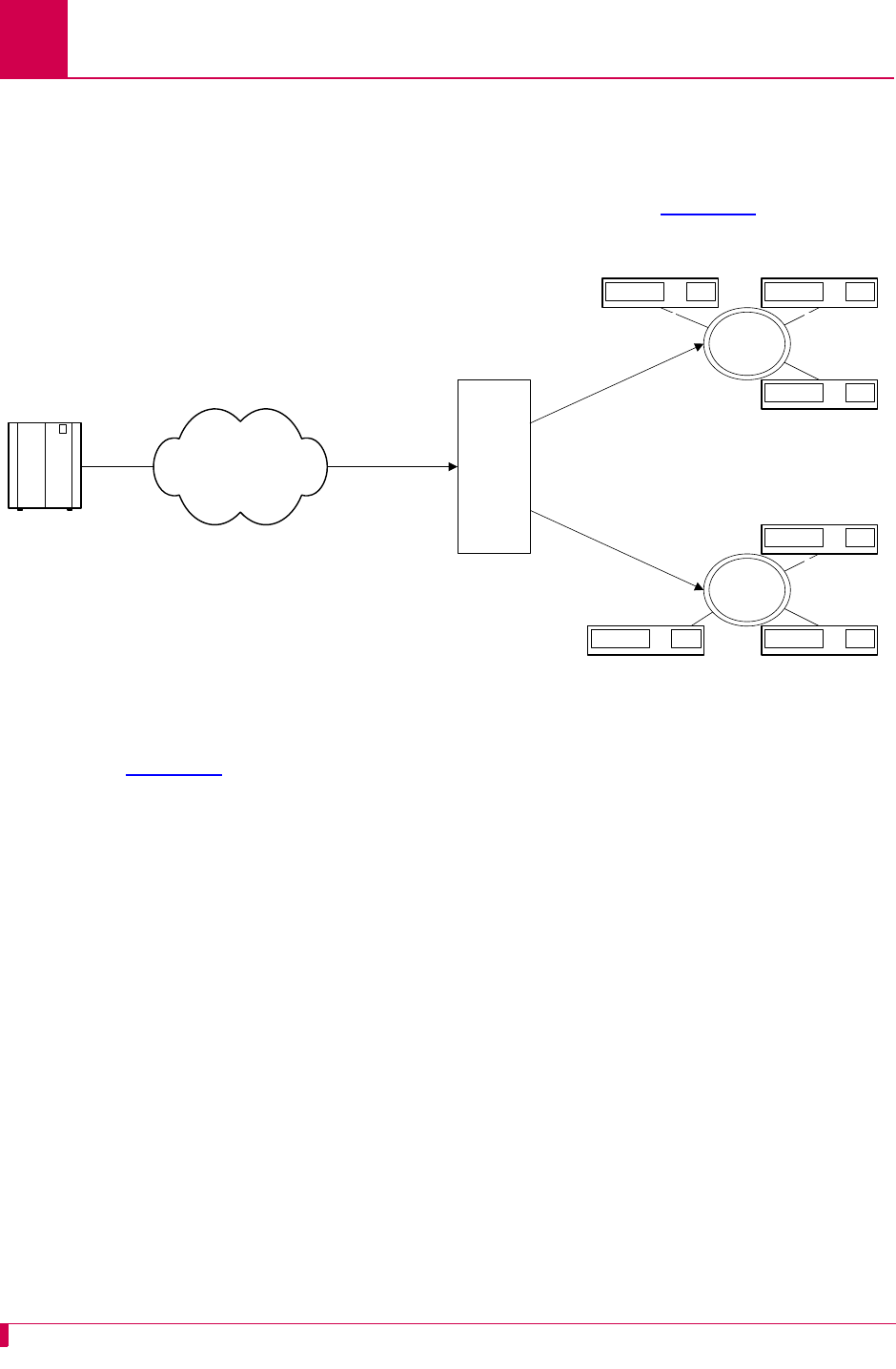
AI296 Version 9.8x User’s Guide
TID Multiplexing: Overview
7-2
Overview
AI296 supports TID multiplexing, which enables a single call from an OSS to fan out
into multiple calls to various NEs. The initiating call may be X.25, asynchronous, or
TCP, but cannot originate from a destination menu. Refer to Figure 7-1 for an
illustration of TID multiplexing.
Figure 7-1 TID Multiplexing Overview
In Figure 7-1, AI296 takes a single call from an OSS and routes TL1 commands to
various NEs by means of the TID in the TL1 command. Similarly, AI296 receives TL1
responses and NE reporting messages from several NEs and routes these messages
to the appropriate OSS. The call to AI296 from the OSS is a parent call. The calls
from AI296 to the various NEs are children calls.
After receiving a TL1 command from the OSS, AI296 checks to see if there is an
existing connection for each TID. If a connection to the appropriate NE is already
established, then AI296 forwards the TL1 command to the NE as specified by the TID.
The following characteristics apply to AI296 when it attempts to connect to an NE:
zIf AI296 is unable to establish a connection to an NE, it will buffer the TL1
command and try to reconnect within 2 seconds.
zAI296 tries to connect up to three times if it cannot immediately establish a
connection.
zAI296 buffers only one TL1 command for each NE. If a connection is made, AI296
forwards the buffered command to the NE.
Sonet NEs
TID4
TID5TID6
Sonet NEs
X.25 Packet Switched
Network
OSS
TID2
TID3
AI296
TID1
TID1
TID2
TID3
TID4
TID5
TID6
TID1
TID2
TID3
TID4
TID5
TID6

AI296 Version 9.8x User’s Guide
TID Multiplexing: Overview
7-3
zIf a connection is not established after four tries or if AI296 receives a TL1
command with an unknown TID, the TL1 command gets discarded and a
message gets logged.
zIf the OSS is disconnected from AI296, all associated children calls to the NEs are
disconnected.
Tip: To access the configuration menu on a Soneplex NE device, you must set the
Packet Window Size to 1.

AI296 Version 9.8x User’s Guide
TID Multiplexing: TID Multiplexing Configuration
7-4
TID Multiplexing Configuration
Establish TID multiplexing by configuring aliases for calls that will go through AI296.
Configure a parent alias to accept the incoming call from the OSS. After doing this,
configure children aliases to route calls to the various network elements. For more
information about aliases, refer to Chapter 8: Alias and Call Routing Configuration.
Configuring the Parent Alias
Note: Kentrox recommends that you do not use connect-on-activity PVCs to
establish a parent connection.
Configuration in the AI198 Menu System
1. Log in to AI198.
2. At the prompt, enter menu to access the Main Menu.
3. For 08+Configure the alias translation table, enter 8. The alias configuration
menu appears.
4. For 01 Alias name, enter the alias name for the call coming from the OSS.
>8
Menu 8
01 Alias name -****************************************************************
02+Simple alias translation
03 Destination -
04 Called address -
05 This alias is visible in the destination menu-----------------------------NO
06 Link number is (1..16) -
07 Caller's address -
08 Call data -
09 App. string -
10 Called protocol -
11 Caller's protocol -
12 Alternate routing alias -
14+Test macros
15 Show entire alias
16 Show the first entry in the alias translation table
17 Show the previous entry in the alias translation table
18 Show the next entry in the alias translation table
19+Delete the above alias translation entry
20 Save the changes made (20b: to the beginning, 20e: to the end)
21 Exit this menu with no changes
Enter item number and optional ",value" then push <CR> key
>

AI296 Version 9.8x User’s Guide
TID Multiplexing: TID Multiplexing Configuration
7-5
5. For 02+Simple alias translation, enter 2. Menu 8.2 appears with the available
translation options.
6. For 04 SLC routing translation, enter 4. Menu 8 reappears with SLC routing
translation selected for menu item 2.
7. If you are using single alias translation, for 03 Destination, enter 3, and the IP
address of AI296.
8. For 08 Call data, enter 8, and the parent name.
Note: When creating the parent name, note that you use the parent name to
make the children alias names. For example, if a parent is named
PARENT1, valid child names would be PARENT1.1 and PARENT1.2.
9. For 09 App. string, enter:
TMUX
n
[ TID:
tid_for_AI296
]
10. For 10 Called protocol, enter 10,=""
11. (optional) For 11 Caller's protocol, enter 11, and the caller's protocol.
12. Save your changes.
>2
Menu 8.2
01 Simple alias translation
02 Multiplexed connection
03 Multiplexed only translation
04 SLC routing translation
21 Exit this menu with no changes
Enter item number and optional ",value" then push <CR> key
>
n
Defines the maximum number of children connections. Valid
values are 1 to 128.
tid_for_AI296
Defines the terminal identifier for AI296.

AI296 Version 9.8x User’s Guide
TID Multiplexing: TID Multiplexing Configuration
7-6
Configuration in the AI296 Local Menu System
Note: To configure aliases in the AI296 local menu system, AI296 must be in
standalone mode.
1. Log in to the AI296 Main Menu.
2. From the AI296 Main Menu, select Alias Menu. The Alias Summary Menu appears.
3. From the Alias Summary Menu, select Add Alias. The Alias Edit Menu appears.
4. For Alias Name, enter the alias name for the call coming from the OSS.
5. If you are using single alias translation, for Destination, enter the IP address of
AI296. By entering a destination value, you are specifying the use of single alias
translation.
6. For Call data, enter the parent name.
Note: When creating the parent name, note that you use the parent name to
make the children alias names. For example, if a parent is named
PARENT1, valid child names would be PARENT1.1 and PARENT1.2.
Alias Edit Menu
Alias Name . . . . .
Destination . . . . .......................................................
Caller's Address . . .......................................................
Called Address . . . .......................................................
Call Data . . . . . .......................................................
Caller's Protocol . .......................................................
Called Protocol . . .......................................................
Application String . .......................................................
Alternate Route . . .......................................................
Description . . . . .......................................................
Display Alias in Destination Menu . . . . . . . . . . . . . . [Yes] No
Alias Location . . . . . . . . . . . . . . . . . . . Beginning [End]
+ Alias Test Menu
Range: {255 characters}
<F1> Help <F2> Send <F4> Close <Ctrl-R> Return to Main Menu

AI296 Version 9.8x User’s Guide
TID Multiplexing: TID Multiplexing Configuration
7-7
7. For Application string, enter:
TMUX
n
[ TID:
tid_for_AI296
]
8. For Called protocol, enter ="".
9. (optional) For Caller's protocol, enter the caller's protocol.
10. Save your changes.
Configuring the Children Aliases
Configuration in the AI198 Menu System
AI296 supports a maximum of 512 child connections. These connections can be X.25,
asynchronous, or TCP/IP.
To configure the child aliases:
1. Log into AI198.
2. At the prompt, enter menu to access the Main Menu.
3. For 08+Configure the alias translation table, enter 8. The alias configuration
menu appears.
n
Defines the maximum number of children connections. Valid
values are 1 to 128.
tid_for_AI296
Defines the terminal identifier for AI296.
>8
Menu 8
01 Alias name -****************************************************************
02+Simple alias translation
03 Destination -
04 Called address -
05 This alias is visible in the destination menu-----------------------------NO
06 Link number is (1..16) -
07 Caller's address -
08 Call data -
09 App. string -
10 Called protocol -
11 Caller's protocol -
12 Alternate routing alias -
14+Test macros
15 Show entire alias
16 Show the first entry in the alias translation table
17 Show the previous entry in the alias translation table
18 Show the next entry in the alias translation table
19+Delete the above alias translation entry
20 Save the changes made (20b: to the beginning, 20e: to the end)
21 Exit this menu with no changes
Enter item number and optional ",value" then push <CR> key
>

AI296 Version 9.8x User’s Guide
TID Multiplexing: TID Multiplexing Configuration
7-8
4. For 01 Alias name, enter:
parent_name
.
m
5. For 02+Simple alias translation, enter 2. Menu 8.2 appears with the available
translation options.
6. For 04 SLC routing translation, enter 4. Menu 8 re-appears with SLC routing
translation selected for menu item 2.
7. If you are using single alias translation, for 03 Destination, enter 3, and the IP
address of AI296. By entering a destination value, you are specifying the use of
single alias translation.
8. For 04 Called address, enter 4, and the called address.
9. For 07 Caller's address, enter 7, and the caller's address.
10. For 08 Call data, enter 8, and the call data information.
parent_name
Defines the name you entered for 08 Call data during the parent
alias configuration.
m
Defines the child number. Valid values are 1 to
n
(specified
during the parent alias configuration).
>2
Menu 8.2
01 Simple alias translation
02 Multiplexed connection
03 Multiplexed only translation
04 SLC routing translation
21 Exit this menu with no changes
Enter item number and optional ",value" then push <CR> key
>

AI296 Version 9.8x User’s Guide
TID Multiplexing: TID Multiplexing Configuration
7-9
11. For 09 App. string, enter:
TID:
tid
12. (optional) For 10 Called protocol, enter 10, and the called protocol.
13. For 11 Caller's protocol, enter 11,="".
Configuration in the AI296 Local Menu System
Note: To configure aliases in the AI296 local menu system, AI296 must be in
standalone mode.
1. Log in to the AI296 Main Menu.
2. From the AI296 Main Menu, select Alias Menu. The Alias Summary Menu appears.
3. From the Alias Summary Menu, select Add Alias. The Alias Edit Menu appears.
tid
Defines the TID of the destination NE. Maximum length is 20 characters.
Alias Edit Menu
Alias Name . . . . .
Destination . . . . .......................................................
Caller's Address . . .......................................................
Called Address . . . .......................................................
Call Data . . . . . .......................................................
Caller's Protocol . .......................................................
Called Protocol . . .......................................................
Application String . .......................................................
Alternate Route . . .......................................................
Description . . . . .......................................................
Display Alias in Destination Menu . . . . . . . . . . . . . . [Yes] No
Alias Location . . . . . . . . . . . . . . . . . . . Beginning [End]
+ Alias Test Menu
Range: {255 characters}
<F1> Help <F2> Send <F4> Close <Ctrl-R> Return to Main Menu

AI296 Version 9.8x User’s Guide
TID Multiplexing: TID Multiplexing Configuration
7-10
4. For Alias name, enter:
parent_name
.
m
5. If you are using single alias translation, for Destination, enter the IP address of
AI296. By entering a destination value, you are specifying the use of single alias
translation.
6. For Called address, enter the called address.
7. For Caller's address, enter the caller's address.
8. For Call Data, enter the call data information.
9. For Application String, enter:
TID:
tid
10. (optional) For Called protocol, enter the called protocol.
11. For Caller's protocol, enter ="".
12. Save your changes.
Example Configurations
The following screens display parent and child alias configurations that do the
following:
1. A call comes in on alias 172.16.1.123 at port 1000 (172.16.1.123#1000).
2. The call fans out into two child calls. 09 App. string in the parent alias
configuration determines the number of children; in this case, it is noted by TMUX2.
The children have the following names: TL1DM.1 and TL1DM.2. These names are
established through 08 Call data in the parent alias configuration. The calls to the
first child will be X.25 through link 1 with X.121 address 123456789012
(X25.1.123456789012). The call to the second child will be X.25 through link 2 with
X.121 address 987654321098 (X25.2.987654321098).
parent_name
Defines the name you entered for 08 Call data during the parent
alias configuration.
m
Defines the child number. Valid values are 1 to
n
(specified
during the parent alias configuration).
tid
Defines the TID of the destination NE. Maximum length is 20 characters.

AI296 Version 9.8x User’s Guide
TID Multiplexing: TID Multiplexing Configuration
7-11
3. AI296 forwards all TL1 commands with TIDs NE-OH-COLUMBUS-1, NE-OH-COLUMBUS-2,
and NE-OH-COLUMBUS-3 through the first child connection. It forwards all TL1
commands with TIDs NE-OH-WORTHINGTON-1 and NE-OH-WORTHINGTON-2 through the
second child connection.
This example displays the parent alias configuration in the AI198 menu system.
>11 TL1
Menu 8
01 Alias name -------------------------------------------------172.16.1.23#1000
02+Simple alias translation
03 Destination -
04 Called address -
05 This alias is visible in the destination menu----------------------------YES
06 Link number is (1..16) -
07 Caller's address -
08 Call data -------------------------------------------------------------TL1DM
09 App. string -----------------------------------------------------------TMUX2
10 Called protocol ---------------------------------------------------------=""
11 Caller's protocol -------------------------------------------------------TL1
12 Alternate routing alias -
14+Test macros
15 Show entire alias
16 Show the first entry in the alias translation table
17 Show the previous entry in the alias translation table
18 Show the next entry in the alias translation table
19+Delete the above alias translation entry
20 Save the changes made (20b: to the beginning, 20e: to the end)
21 Exit this menu with no changes
Enter item number and optional ",value" then push <CR> key
>

AI296 Version 9.8x User’s Guide
TID Multiplexing: TID Multiplexing Configuration
7-12
This example displays the parent alias configuration in the AI296 menu system.
Note: To configure aliases in the AI296 local menu system, AI296 must be in
standalone mode.
Alias Edit Menu
Alias Name . . . . . ...................................... 172.16.1.23#1000
Destination . . . . .......................................................
Caller's Address . . .......................................................
Called Address . . . .......................................................
Call Data . . . . . ................................................. TL1DM
Caller's Protocol . ................................................... TL1
Called Protocol . . ................................................... =""
Application String . ................................................. TMUX2
Alternate Route . .
Description . . . . .......................................................
Display Alias in Destination Menu . . . . . . . . . . . . . . [Yes] No
Alias Location . . . . . . . . . . . . . . . . . . . Beginning [End]
+ Alias Test Menu
Range: {255 characters}
<F1> Help <F2> Send <F4> Close <Ctrl-R> Return to Main Menu

AI296 Version 9.8x User’s Guide
TID Multiplexing: TID Multiplexing Configuration
7-13
These examples display two of the child alias configurations in the AI198 menu
system.
>11 =""
Menu 8
01 Alias name ----------------------------------------------------------TL1DM.1
02+Simple alias translation
03 Destination -
04 Called address -------------------------------------------X25.1.123456789012
05 This alias is visible in the destination menu----------------------------YES
06 Link number is (1..16) -
07 Caller's address -
08 Call data -
09 App. string --TID:NE-OH-COLUMBUS-1 TID:NE-OH-COLUMBUS-2 TID:NE-OH-COLUMBUS-3
10 Called protocol -
11 Caller's protocol -------------------------------------------------------=""
12 Alternate routing alias -
14+Test macros
15 Show entire alias
16 Show the first entry in the alias translation table
17 Show the previous entry in the alias translation table
18 Show the next entry in the alias translation table
19+Delete the above alias translation entry
20 Save the changes made (20b: to the beginning, 20e: to the end)
21 Exit this menu with no changes
Enter item number and optional ",value" then push <CR> key
>
>11 =""
Menu 8
01 Alias name ----------------------------------------------------------TL1DM.2
02+Simple alias translation
03 Destination -
04 Called address -------------------------------------------X25.2.987654321098
05 This alias is visible in the destination menu----------------------------YES
06 Link number is (1..16) -
07 Caller's address -
08 Call data -
09 App. string -----------------TID:NE-OH-WORTHINGTON-1 TID:NE-OH-WORTHINGTON-2
10 Called protocol -
11 Caller's protocol -------------------------------------------------------=""
12 Alternate routing alias -
14+Test macros
15 Show entire alias
16 Show the first entry in the alias translation table
17 Show the previous entry in the alias translation table
18 Show the next entry in the alias translation table
19+Delete the above alias translation entry
20 Save the changes made (20b: to the beginning, 20e: to the end)
21 Exit this menu with no changes
Enter item number and optional ",value" then push <CR> key
>

AI296 Version 9.8x User’s Guide
TID Multiplexing: TID Multiplexing Configuration
7-14
These examples display two of the child alias configurations in the AI296 menu
system.
Note: To configure aliases in the AI296 local menu system, AI296 must be in
standalone mode.
Alias Edit Menu
Alias Name . . . . . ............................................... TL1DM.1
Destination . . . . .......................................................
Caller's Address . . .......................................................
Called Address . . . .................................... X25.1.123456789012
Call Data . . . . . .......................................................
Caller's Protocol . ................................................... =""
Called Protocol . . .......................................................
Application String . TID:NE-OH-COLUMBUS-1 TID:NE-OH-COLUMBUS-2 TID:NE-OH-COL
Alternate Route . . .......................................................
Description . . . . .......................................................
Display Alias in Destination Menu . . . . . . . . . . . . . . [Yes] No
+ Alias Test Menu
<F1> Help <F2> Send <F4> Close <Ctrl-R> Return to Main Menu
Alias Edit Menu
Alias Name . . . . . ............................................... TL1DM.2
Destination . . . . .......................................................
Caller's Address . . .......................................................
Called Address . . . .................................... X25.2.987654321098
Call Data . . . . . .......................................................
Caller's Protocol . ................................................... =""
Called Protocol . . .......................................................
Application String . ....... TID:NE-OH-WORTHINGTON-1 TID:NE-OH-WORTHINGTON-2
Alternate Route . .
Description . . . . .......................................................
Display Alias in Destination Menu . . . . . . . . . . . . . . [Yes] No
+ Alias Test Menu
Range: {255 characters}
<F1> Help <F2> Send <F4> Close <Ctrl-R> Return to Main Menu

AI296 Version 9.8x User’s Guide
TID Multiplexing: TID Multiplexing Troubleshooting
7-15
TID Multiplexing Troubleshooting
If an OSS is not getting a response from an NE, it can send a TL1 retrieve header
command (RTRV-HDR) to determine if the problem is with the NE or with AI296. The
parent connection on AI296 responds to RTRV-HDR commands that have the same TID
as the one configured for the card.
Tip: For more information regarding TL1 commands, responses, and formats, refer
to the Belcore document GR-833-CORE.
RTRV-HDR
This command is used primarily as an aliveness check.
Format
RTRV-HDR:[
tid
]::
ctag
;
Parameters
Normal Response Format
This example displays the format of the response that appears when RTRV-HDR is
successfully executed:
Table 7-1 describes each of the items in the above response format.
tid
Defines the TID for AI296. Note that the TID and SID are the same.
ctag
Defines the correlation tag used to correlate responses to input commands.
Each input command has a unique
ctag
. Maximum length is 6 characters.
Responses include the identical
ctag
.
<cr><lf><lf>
<sp><sp><sp><SID><sp><YY-MM-DD><sp><HH:MM:SS><cr><lf>
M<sp><sp><ctag><sp>COMPLD<cr><lf>;
Table 7-1 RTRV-HDR Response Format Description
Response Item Description
cr Specifies a carriage return.
lf Specifies a line feed.
sp Specifies a space.
SID Specifies a system identifier (system ID).

AI296 Version 9.8x User’s Guide
TID Multiplexing: TID Multiplexing Troubleshooting
7-16
Normal Response Example
This example displays the response that appears when RTRV-HDR:AI232:12345; is
executed.
Error Response Format
If AI296 receives TL1 commands other than RTRV-HDR with the same card TID, it
responds with a deny message. This example displays the deny message format.
Table 7-2 describes each of the items in the above response format.
YY-MM-DD Specifies the date.
HH:MM:SS Specifies the time of day.
ctag Specifies the correlation tag.
COMPLD Specifies completion. The Input requirement is satisfied.
AI296 97-01-01 05:06:39
M 12345 COMPLD;
<cr><lf><lf>
<sp><sp><sp><SID><sp><YY-MM-DD><sp><HH:MM:SS><cr><lf>
M<sp><sp><ctag><sp>DENY<cr><lf>
<sp><sp><sp><errcde><cr><lf>;
Table 7-2 Error Response Format Description
Response Item Description
cr Specifies a carriage return.
lf Specifies a line feed.
sp Specifies a space.
SID Specifies a system identifier (system ID).
YY-MM-DD Specifies the date.
HH:MM:SS Specifies the time of day.
ctag Specifies the correlation tag.
DENY Specifies that the input requirement is not satisfied.
Table 7-1 RTRV-HDR Response Format Description (Continued)
Response Item Description

AI296 Version 9.8x User’s Guide
TID Multiplexing: TID Multiplexing Troubleshooting
7-17
Error Response Example
This example displays the response that appears if RTRV-HDR fails.
Diagnostics for TID Multiplexing
To view information on TID multiplexed calls and the associated TIDs, use
diag-tconn. This command displays a list of all connections on the card in the same
format as diag-conn. However, diag-tconn is not interactive.
Use this command either from the AI296 shell or through AI198 as a winslc
command. Refer to diag-tconn on page 9-49 for more information.
errcde Specifies the error code.
AI296 97-01-01 05:06:39
M 12345 DENY
IIAC;
Table 7-2 Error Response Format Description (Continued)
Response Item Description

AI296 Version 9.8x User’s Guide
TID Multiplexing: TID Multiplexing Troubleshooting
7-18

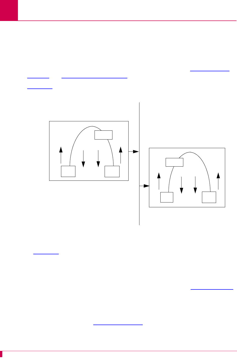
AI296 Version 9.8x User’s Guide
Alias and Call Routing Configuration: Overview
8-2
Overview
AI296 uses aliases to route calls across the backplane of AIswitch. Each incoming
call’s routing information must match an entry in the alias table, or else the call is
rejected. When AI296 is in switch mode, the alias table is stored on AI198. When
AI296 is in standalone mode, the alias table is stored in AI296’s local memory. For
more information about alias translation and macros, see sections Call Routing on
page 8-5 and Alias Macros on page 8-38.
Figure 8-1 displays a typical call processing data flow scenario where AI296 is used.
Figure 8-1 Call Data Flow
In Figure 8-1, an X.25 protocol call is coming into AI296 card A and needs to pass
over the IRB and be sent out AI296 card B. Refer to the figure to follow the flow of the
call.
The following events occur if the data flow is from left to right:
1. The data comes into AI296 card A as an X.25 packet. Refer to X.25 on page 6-4
for information about X.25
2. The data travels upstream and is converted into a TCP call.
3. The data starts downstream through the AEPN protocol option to preserve the
packetization. Refer to AEPN on page 8-29 for information about the AEPN
protocol.
4. The data is sent out AI296 card A over TCP on the IRB.
downstream
X.25 TCP
AEPN
upstream
Incoming
IRB
AI296 Card A
X.25
call
Outgoing
TCP/IP
call
downstream
TCP X.25
upstream
AEPN
AI296 Card B
Incoming
TCP/IP
call
Outgoing
X25 call to
X25.2.67891
IP address
172.16.30.100
IP address
172.16.30.200
downstream
upstream
downstream
upstream

AI296 Version 9.8x User’s Guide
Alias and Call Routing Configuration: Overview
8-3
5. The TCP packet is received by AI296 card B.
6. The data travels upstream through the AEPN protocol option to preserve
packetization.
7. The data packet is converted, travels downstream, and is transmitted out AI296
using an X.25 protocol with the original packetizing characteristics preserved.
This is an example configuration in the AI198 menu system for AI296 A:
>8
Menu 8
01 Alias name ----------------------------------------------------------TOCARDB
02+Simple alias translation
03 Destination -
04 Called address ------------------------------------------172.16.30.200 #5000
05 This alias is visible in the destination menu-----------------------------NO
06 Link number is (1..16) -
07 Caller's address -
08 Call data -
09 App. string -
10 Called protocol --------------------------------------------------------AEPN
11 Caller's protocol -------------------------------------------------------=""
12 Alternate routing alias -
14+Test macros
15 Show entire alias
16 Show the first entry in the alias translation table
17 Show the previous entry in the alias translation table
18 Show the next entry in the alias translation table
19+Delete the above alias translation entry
20 Save the changes made (20b: to the beginning, 20e: to the end)
21 Exit this menu with no changes
Enter item number and optional ",value" then push <CR> key
>

AI296 Version 9.8x User’s Guide
Alias and Call Routing Configuration: Overview
8-4
This is an example configuration in the AI198 menu system for AI296 B:
>8
Menu 8
01 Alias name -----------------------------------------------172.16.30.200#5000
02+Simple alias translation
03 Destination -
04 Called address --------------------------------------------------X25.2.67891
05 This alias is visible in the destination menu----------------------------YES
06 Link number is (1..16) -
07 Caller's address -
08 Call data -
09 App. string -
10 Called protocol -
11 Caller's protocol ------------------------------------------------------AEPN
12 Alternate routing alias -
14+Test macros
15 Show entire alias
16 Show the first entry in the alias translation table
17 Show the previous entry in the alias translation table
18 Show the next entry in the alias translation table
19+Delete the above alias translation entry
20 Save the changes made (20b: to the beginning, 20e: to the end)
21 Exit this menu with no changes
Enter item number and optional ",value" then push <CR> key
>

AI296 Version 9.8x User’s Guide
Alias and Call Routing Configuration: Call Routing
8-5
Call Routing
To route calls with AI296, you must configure an alias for a source and destination
protocol.
Note: Aliases created in AI198 are not visible to AI296 when it is running in
standalone mode. However, you can configure aliases in the AI296 local menu
system when it is in standalone mode.
Configuring an Alias in the AI198 Menu System
Note: Specific configuration information about menu items in the following procedure
is located in section Source/Destination Protocol Tables for the AI198 Menu
System on page 8-12.
To configure an alias in the AI198 Menu System:
1. Log in to AI198.
2. At the prompt, type menu. The main menu appears.
3. To access menu 08+Configure the alias translation table, enter 8. Menu 8 appears:
4. For 01 Alias name -, enter 1, followed by the alias name for the incoming (source)
call.
AI198 translates the alias name into a call of the type defined in the remaining
alias menu items.
>8
Menu 8
01 Alias name -****************************************************************
02+Simple alias translation
03 Destination -
04 Called address -
05 This alias is visible in the destination menu-----------------------------NO
06 Link number is (1..16) -
07 Caller's address -
08 Call data -
09 App. string -
10 Called protocol -
11 Caller's protocol -
12 Alternate routing alias -
14+Test macros
15 Show entire alias
16 Show the first entry in the alias translation table
17 Show the previous entry in the alias translation table
18 Show the next entry in the alias translation table
19+Delete the above alias translation entry
20 Save the changes made (20b: to the beginning, 20e: to the end)
21 Exit this menu with no changes
Enter item number and optional ",value" then push <CR> key
>

AI296 Version 9.8x User’s Guide
Alias and Call Routing Configuration: Call Routing
8-6
Note: The alias name may include leading, trailing, or embedded wildcard
matching characters. You may enter an asterisk (*) which replaces zero or
more characters, a question mark (?) which replaces one character, or an
alias macro that starts with an equal sign (=).
For information on acceptable alias naming elements and conventions, refer to
section Source/Destination Protocol Tables for the AI198 Menu System on page
8-12.
5. To access menu 02+Simple alias translation, enter 2. Menu 8.2 appears:
6. To select 04 SLC routing translation, enter 4. Menu 8 reappears with the SLC
routing translation configuration items.
Important: Menu item 04 SLC routing translation is the only valid menu item for
AI296. Use SLC routing translations to route calls through cards that
support non-time division subchannel (TDS) connections.
7. (optional) If you are routing calls between two AI296 cards, enter 3, and the IP
address of the remote AI296.
8. For 04 Called address -, enter 4, and the the called (destination) address.
The called (destination) address defines the phone number being called.
Maximum length is 14 characters. The actual address or an alias macro can be
entered here.
>2
Menu 8.2
01 Simple alias translation
02 Multiplexed connection
03 Multiplexed only translation
04 SLC routing translation
21 Exit this menu with no changes
Enter item number and optional ",value" then push <CR> key
>

AI296 Version 9.8x User’s Guide
Alias and Call Routing Configuration: Call Routing
8-7
9. For 05 This alias is visible in the destination menu, enter 5 to toggle between Yes
and No.
This setting specifies if the alias will appear in the welcome screen.
10. (optional) For 08 Call data -, enter 8, and the call user data.
Call data is dependent on the type of SLC being used. It may be directly entered
as an alias macro.
11. (optional) For 10 Called protocol -, enter 10, and the called protocol type.
For more information about protocol types, refer to Protocol Processing Modules
on page 8-29.
12. (optional) For 11 Caller's protocol -, enter 11, and the caller’s protocol type.
For more information about protocol types, refer to Protocol Processing Modules
on page 8-29.
13. For 20 Save the changes made, enter 20 to save the alias configuration.
14. Repeat this procedure for additional alias configurations.
Configuring an Alias in the AI296 Menu System
Note: Specific configuration information about menu items in the following procedure
is located in section Source/Destination Protocol Tables for the AI296 Menu
System on page 8-20.
To configure an alias in the AI296 Menu System:
1. Log in to AI296.
2. At the prompt, type menu. The AI296 Main Menu appears.
3. Access the Alias Menu. The Alias Summary Menu appears.

AI296 Version 9.8x User’s Guide
Alias and Call Routing Configuration: Call Routing
8-8
4. From the the Alias Summary Menu, select [Add Alias]. The Alias Edit Menu
appears:
5. For Alias Name, enter the alias name for the incoming (source) call.
AI296 translates the alias name into a call of the type defined in the remaining
alias menu items.
Note: The alias name may include leading, trailing, or embedded wildcard
matching characters. You may enter an asterisk (*) which replaces zero or
more characters, a question mark (?) which replaces one character, or an
alias macro that starts with an equal sign (=).
For information on acceptable alias naming elements and conventions, refer to
section Source/Destination Protocol Tables for the AI296 Menu System on page
8-20.
6. (optional) If you are routing calls between two AI296 cards, enter the IP address
of the remote AI296 in the destination field.
7. (optional) For Called Address, enter the called (destination) address.
The called (destination) address defines the phone number being called.
Maximum length is 14 characters. The actual address or an alias macro can be
entered here.
Alias Edit Menu
Alias Name . . . . .
Destination . . . . .......................................................
Caller's Address . . .......................................................
Called Address . . . .......................................................
Call Data . . . . . .......................................................
Caller's Protocol . .......................................................
Called Protocol . . .......................................................
Application String . .......................................................
Alternate Route . . .......................................................
Description . . . . .......................................................
Display Alias in Destination Menu . . . . . . . . . . . . . . [Yes] No
Alias Location . . . . . . . . . . . . . . . . . . . Beginning [End]
+ Alias Test Menu
Range: {255 characters}
<F1> Help <F2> Send <F4> Close <Ctrl-R> Return to Main Menu

AI296 Version 9.8x User’s Guide
Alias and Call Routing Configuration: Call Routing
8-9
8. (optional) For Call Data, enter the call user data.
Call data is dependent on the type of SLC being used. It may be directly entered
as an alias macro.
9. (optional) For Caller's Protocol, enter the caller’s protocol type.
For more information about protocol types, refer to Protocol Processing Modules
on page 8-29.
10. (optional) For Called Protocol, enter the called protocol type.
For more information about protocol types, refer to Protocol Processing Modules
on page 8-29.
11. For Display Alias in Destination Menu, select Yes or No.
This setting specifies if the alias will appear in the welcome screen.
12. For Alias Location, select Beginning or End to place the alias at the beginning or end
of the alias table.
13. Select <F2> Send to save the changes.
14. Repeat this procedure for additional alias configurations.
Arranging Aliases in the Alias Table
To arrange aliases in the alias table:
1. From the AI296 Main Menu, access the Alias Menu. The Alias Summary Menu
appears:
Alias Summary Menu
Find alias:
[Add Alias]
[Sort]
+ alias4 [Move] [Delete]
+ alias2 [Move] [Delete]
+ alias1 [Move] [Delete]
+ alias3 [Move] [Delete]
Range: {255 characters}
<F1> Help <F4> Close <Ctrl-R> Return to Main Menu

AI296 Version 9.8x User’s Guide
Alias and Call Routing Configuration: Call Routing
8-10
2. From the Alias Summary Menu, select one of the following options:
zSelect Sort to sort the aliases alphabetically.
zSelect Move next to the desired alias and move it to the top or bottom of the list,
or up or down in the list.
3. Select <F4> Close to exit the Alias Summary Menu.
Configuring an Alias with X.25 Keep-Alive
Some devices will go to sleep if no data is received within a certain timeframe. You
can prevent that by sending a receive-ready (RR) frame periodically on a virtual circuit
(VC). You can customize the time period by configuring the application string of the
Alias menu.
1. Access the Alias Edit Menu. (For information about accessing the Alias Edit
Menu, refer to Configuring an Alias in the AI296 Menu System on page 8-7.)
Alias Edit Menu
Alias Name . . . . . .............................................. X.25.4.1
Destination . . . . .......................................................
Caller's Address . . .......................................................
Called Address . . . .......................................... 10.39.3.89#7
Call Data . . . . . .......................................................
Caller's Protocol . .......................................................
Called Protocol . . .......................................................
Application String . ........................................... X25KA -s 20
Alternate Route . .
Description . . . . .......................................................
Display Alias in Destination Menu . . . . . . . . . . . . . . [Yes] No
Alias Test Menu
Range: {255 characters}
<F1> Help <F2> Send <F4> Close <Ctrl-R> Return to Main Menu

AI296 Version 9.8x User’s Guide
Alias and Call Routing Configuration: Call Routing
8-11
2. In the Alias Edit Menu, select Application String and enter the X-25 keep-alive
string as follows:
X25KA [-s | -d] period
where:
X25KA Notifies the 296 that this is the X-25 keep-alive feature.
period The period between each RR on the VC. This value is in tenths of
second. In the example above, an RR would be sent every 2
seconds.
-d, -s - If the -d flag is given, the destination will send out the RRs if it is an
X.25 link. If the -s flag is given, then only the source side of the
connection will send out the RRs if it is an X.25 link. If neither is
given, then it will send out RRs on the side that is an X.25 link and
both if both are X.25 links.

AI296 Version 9.8x User’s Guide
Alias and Call Routing Configuration: Source/Destination Protocol Tables
8-12
Source/Destination Protocol Tables
The following parameters are referred to in the tables:
Source/Destination Protocol Tables for the AI198 Menu System
The following tables are organized according to source protocols. Match the
destination protocol with the source protocol to find the appropriate menu item
entries:
zAsynchronous Source Without Breaks (AI198)
zAsynchronous Source With Breaks (AI198)
zX.25 SVC Source Without Breaks (AI198)
zX.25 SVC Source With Breaks (AI198)
zX.25 PVC Source Without Breaks (AI198)
zX.25 PVC Source With Breaks (AI198)
zTCP/IP Source Without Telnet Breaks (AI198)
zTCP/IP Source With Telnet Breaks (AI198)
call_data
Defines the call data. Maximum length is 16 characters.
called_address
Defines the address being called. Maximum length is 14
characters.
caller_address
Defines the address of the caller. Maximum length is 14
characters.
ip_address
Defines the IP address in dotted decimal format. The # symbol
must be entered as a field separator between the
ip_address
field and the
tcp_port_number
field.
lcn
Defines the logical channel number.
link_number
Defines the number of the serial link.
tcp_port_number
Defines the TCP port number. Valid values are from 1 to
65535.

AI296 Version 9.8x User’s Guide
Alias and Call Routing Configuration: Source/Destination Protocol Tables
8-13
Table 8-1 Asynchronous Source Without Breaks (AI198)
Source Destination Menu Item Information
Async Async 01 ASY.
link_number
04 PVC
08 ASY.
link_number
Async X.25 SVC 01 ASY.
link_number
04 The following options are available:
zX25.
link_number
.
called_address
zX25.
link_number
. {
caller_address
|
call_user_data
}
Note:
called_address
must be a valid
X.121 address.
Async X.25 PVC 01 ASY.
link_number
04 PVC
08 X25.
link_number
.
lcn
Async TCP 01 ASY.
link_number
04
ip_address
#
tcp_port_number

AI296 Version 9.8x User’s Guide
Alias and Call Routing Configuration: Source/Destination Protocol Tables
8-14
Table 8-2 Asynchronous Source With Breaks (AI198)
Source Destination Menu Item Information
Async,
Async
TL1,
Async
packetized
on a CR
(or .02 s
idle time)
X.25 SVC
with X.29
break
01 ASY.
link_number
04 The following options are available:
zX25.
link_number
.
called_address
zX25.
link_number
.{
caller_address
|
call_user_data
}
Note:
called_address
must be a valid
X.121 address.
11 The following options are available:
zAsync: leave blank
zAsync TL1: TL1 (Refer to TL1 on
page 8-33)
zAsync packetized: PKT -P13 -I2
(Refer to PKT on page 8-32)
10 PAD (Refer to PAD on page 8-30)
Async,
Async
TL1,
Async
packetized
on a CR
(or .02 s
idle time)
X.25 PVC
with X.29
break
01 ASY.
link_number
04 PVC
08 X25.
link_number
.
lcn
11 The following options are available:
zAsync: leave blank
zAsync TL1: TL1 (Refer to TL1 on
page 8-33)
zAsync packetized: PKT -P13 -I2
(Refer to PKT on page 8-32)
10 PAD (Refer to PAD on page 8-30)
Async TCP with
telnet break 01 ASY.
link_number
04
ip_address
#
tcp_port_number
10 TN (Refer to TN on page 8-35)

AI296 Version 9.8x User’s Guide
Alias and Call Routing Configuration: Source/Destination Protocol Tables
8-15
Table 8-3 X.25 SVC Source Without Breaks (AI198)
Source Destination Menu Item Information
X.25 SVC X.25 SVC 01 Call user data or called address or
caller’s address
04 The following options are available:
zX25.
link_number
.
called_address
zX25.
link_number
.{
caller_address
|
call_user_data
}
Note:
called_address
must be a valid
X.121 address.
X.25 SVC X.25 PVC 01 Call user data or called address or
caller’s address
04 PVC
08 X25.
link_number
.
lcn
X.25 SVC TCP 01 Call user data or called address or
caller’s address
04
ip_address
#
tcp_port_number
X.25 SVC AI193-TX
TCP with N
protocol
option
01 Call user data or called address or
caller’s address
04
ip_address
#
tcp_port_number
10 AEP (Refer to AEP on page 8-29)
X.25 SVC Async 01 Call user data or called address or
caller’s address
04 PVC
08 ASY.
link_number

AI296 Version 9.8x User’s Guide
Alias and Call Routing Configuration: Source/Destination Protocol Tables
8-16
Table 8-4 X.25 SVC Source With Breaks (AI198)
Source Destination Menu Item Information
X.25 SVC,
X.25 SVC
and reply to
X.29 break
TCP with
telnet break 01 Call user data or called address or
caller’s address
04
ip_address
#
tcp_port_number
11 PAD (Refer to PAD on page 8-30)
10 TN (Refer to TN on page 8-35)
X.25 SVC AI193-TX
TCP with N
protocol
option
01 Call user data or called address or
caller’s address
04
ip_address
#
tcp_port_number
Called
protocol AEP (Refer to AEP on page 8-29)
X.25 SVC,
X.25 SVC
with TL1
packetizing
and X.29
break
Async with
async break,
Async TL1
with async
break,
Async
packetized
on CR (or
.02 s idle
time)
Alias name Call user data or called address or
caller’s address
Called
address PVC
Call data ASY.
link_number
Caller’s
protocol The following options are available:
zSVC: PAD
(Refer to PAD on page 8-30)
zSVC with TL1: PAD TL1
(Refer to PAD on page 8-30 and
TL1 on page 8-33)
Called
protocol The following options are available:
zAsync: leave blank
zAsync TL1: TL1
(Refer to TL1 on page 8-33)
zAsync packetized: PKT -P13 -I2
(Refer to PKT on page 8-32)

AI296 Version 9.8x User’s Guide
Alias and Call Routing Configuration: Source/Destination Protocol Tables
8-17
Table 8-5 X.25 PVC Source Without Breaks (AI198)
Source Destination Menu Item Information
X.25 PVC X.25 SVC Alias name X25.
link_number
.
lcn
Called
address The following options are available:
zX25.
link_number
.
called_address
zX25.
link_number
.{
caller_address
|
call_user_data
}
Note:
called_address
must be a valid
X.121 address.
X.25 PVC X.25 PVC Alias name X25.
link_number
.
lcn
Called
address PVC
Call data X25.
link_number
.
lcn
X.25 PVC TCP Alias name X25.
link_number
.
lcn
Called
address
ip_address
#
tcp_port_number
X.25 PVC Async Alias name X25.
link_number
.
lcn
Called
address PVC
Call data ASY.
link_number
Table 8-6 X.25 PVC Source With Breaks (AI198)
Source Destination Menu Item Information
X.25 PVC,
X.25 PVC
and reply to
X.29 break
TCP with
telnet break Alias name X25.
link_number
.
lcn
Called
address
ip_address
#
tcp_port_number
Caller’s
protocol PAD (Refer to PAD on page 8-30)
Called
protocol TN (Refer to TN on page 8-35)

AI296 Version 9.8x User’s Guide
Alias and Call Routing Configuration: Source/Destination Protocol Tables
8-18
X.25 PVC,
X.25 PVC
with TL1
packetizing
and X.29
break
Async with
async break,
Async TL1
with async
break, Async
packetized on
a CR
(or .02 s idle
time)
Alias name X25.
link_number
.
lcn
Called
address PVC
Call data ASY.
link_number
Caller’s
protocol The following options are available:
zX.25 PVC: PAD
(Refer to PAD on page 8-30)
zX.25 PVC TL1: PAD TL1
(Refer to PAD on page 8-30 and
TL1 on page 8-33)
Called
protocol The following options are available:
zAsync: leave blank
zAsync TL1: TL1
(Refer to TL1 on page 8-33)
zAsync packetized: PKT -P13 -I2
(Refer to PKT on page 8-32)
Table 8-7 TCP/IP Source Without Telnet Breaks (AI198)
Source Destination Menu Item Information
TCP X.25 SVC Alias name
ip_address
#
tcp_port_number
Called
address The following options are available:
zX25.
link_number
.
called_address
zX25.
link_number
.{
caller_address
|
call_user_data
}
Note:
called_address
must be a valid
X.121 address.
TCP X.25 PVC Alias name
ip_address
#
tcp_port_number
Called
address PVC
Call data X25.
link_number
.
lcn
Table 8-6 X.25 PVC Source With Breaks (AI198) (Continued)
Source Destination Menu Item Information

AI296 Version 9.8x User’s Guide
Alias and Call Routing Configuration: Source/Destination Protocol Tables
8-19
TCP TCP Alias name
ip_address
#
tcp_port_number
Called
address
ip_address
#
tcp_port_number
TCP Async Alias name
ip_address
#
tcp_port_number
Called
address PVC
Call data ASY.
link_number
Table 8-8 TCP/IP Source With Telnet Breaks (AI198)
Source Destination Menu Item Information
TCP X.25 SVC
with X.29
break
Alias name
ip_address
#
tcp_port_number
Called
address The following options are available:
zX25.
link_number
.
called_address
zX25.
link_number
.{
caller_address
|
call_user_data
}
Note:
called_address
must be a valid
X.121 address.
Caller’s
protocol TN (Refer to TN on page 8-35)
Called
protocol PAD (Refer to PAD on page 8-30)
TCP X.25 PVC
with X.29
break
Alias name
ip_address
#
tcp_port_number
Called
address PVC
Call data X25.
link_number
.
lcn
Caller’s
protocol TN (Refer to TN on page 8-35)
Called
protocol PAD (Refer to PAD on page 8-30)
Table 8-7 TCP/IP Source Without Telnet Breaks (AI198) (Continued)
Source Destination Menu Item Information

AI296 Version 9.8x User’s Guide
Alias and Call Routing Configuration: Source/Destination Protocol Tables
8-20
Source/Destination Protocol Tables for the AI296 Menu System
The following tables are organized according to source protocols. Match the
destination protocol with the source protocol to find the appropriate menu item
entries:
zAsynchronous Source Without Breaks (AI296)
zAsynchronous Source With Breaks (AI296)
zX.25 SVC Source Without Breaks (AI296)
zX.25 SVC Source With Breaks (AI296)
zX.25 PVC Source Without Breaks (AI296)
zX.25 PVC Source With Breaks (AI296)
zTCP/IP Source Without Telnet Breaks (AI296)
zTCP/IP Source With Telnet Breaks (AI296)
TCP Async with
async break Alias name
ip_address
#
tcp_port_number
Called
address PVC
Call data ASY.
link_number
Caller’s
protocol TN (Refer to TN on page 8-35)
Table 8-8 TCP/IP Source With Telnet Breaks (AI198) (Continued)
Source Destination Menu Item Information
Table 8-9 Asynchronous Source Without Breaks (AI296)
Source Destination Menu Item Information
Async Async Alias name ASY.
link_number
Called
address PVC
Call data ASY.
link_number

AI296 Version 9.8x User’s Guide
Alias and Call Routing Configuration: Source/Destination Protocol Tables
8-21
Async X.25 SVC Alias name ASY.
link_number
Called
address The following options are available:
zX25.
link_number
.
called_address
zX25.
link_number
. {
caller_address
|
call_user_data
}
Note:
called_address
must be a valid
X.121 address.
Async X.25 PVC Alias name ASY.
link_number
Called
address PVC
Call data X25.
link_number
.
lcn
Async TCP Alias name ASY.
link_number
Called
address
ip_address
#
tcp_port_number
Table 8-9 Asynchronous Source Without Breaks (AI296) (Continued)
Source Destination Menu Item Information

AI296 Version 9.8x User’s Guide
Alias and Call Routing Configuration: Source/Destination Protocol Tables
8-22
Table 8-10 Asynchronous Source With Breaks (AI296)
Source Destination Menu Item Information
Async,
Async
TL1,
Async
packetized
on a CR
(or.02 s
idle time)
X.25 SVC
with X.29
break
Alias name ASY.
link_number
Called
address The following options are available:
zX25.
link_number
.
called_address
zX25.
link_number
.{
caller_address
|
call_user_data
}
Note:
called_address
must be a valid
X.121 address.
Caller’s
protocol The following options are available:
zAsync: leave blank
zAsync TL1: TL1 (Refer to TL1 on
page 8-33)
zAsync packetized: PKT -P13 -I2
(Refer to PKT on page 8-32)
Called
protocol PAD (Refer to PAD on page 8-30)
Async,
Async
TL1,
Async
packetized
on a CR
(or .02 s
idle time)
X.25 PVC
with X.29
break
Alias name ASY.
link_number
Called
address PVC
Call data X25.
link_number
.
lcn
Caller’s
protocol The following options are available:
zAsync: leave blank
zAsync TL1: TL1 (Refer to TL1 on
page 8-33)
zAsync packetized: PKT -P13 -I2
(Refer to PKT on page 8-32)
Called
protocol PAD (Refer to PAD on page 8-30)
Async TCP with
telnet break Alias name ASY.
link_number
Called
address
ip_address
#
tcp_port_number
Called
protocol TN (Refer to TN on page 8-35)

AI296 Version 9.8x User’s Guide
Alias and Call Routing Configuration: Source/Destination Protocol Tables
8-23
Table 8-11 X.25 SVC Source Without Breaks (AI296)
Source Destination Menu Item Information
X.25 SVC X.25 SVC Alias name Call user data or called address or
caller’s address
Called
address The following options are available:
zX25.
link_number
.
called_address
zX25.
link_number
.{
caller_address
|
call_user_data
}
Note:
called_address
must be a valid
X.121 address.
X.25 SVC X.25 PVC Alias name Call user data or called address or
caller’s address
Called
address PVC
Call data X25.
link_number
.
lcn
X.25 SVC TCP Alias name Call user data or called address or
caller’s address
Called
address
ip_address
#
tcp_port_number
X.25 SVC AI193-TX
TCP with N
protocol
option
Alias name Call user data or called address or
caller’s address
Called
address
ip_address
#
tcp_port_number
Called
protocol AEP (Refer to AEP on page 8-29)
X.25 SVC Async Alias name Call user data or called address or
caller’s address
Called
address PVC
Call data ASY.
link_number

AI296 Version 9.8x User’s Guide
Alias and Call Routing Configuration: Source/Destination Protocol Tables
8-24
Table 8-12 X.25 SVC Source With Breaks (AI296)
Source Destination Menu Item Information
X.25 SVC,
X.25 SVC
and reply to
X.29 break
TCP with
telnet break Alias name Call user data or called address or
caller’s address
Called
address
ip_address
#
tcp_port_number
Caller’s
protocol PAD (Refer to PAD on page 8-30)
Called
protocol TN (Refer to TN on page 8-35)
X.25 SVC AI193-TX
TCP with N
protocol
option
Alias name Call user data or called address or
caller’s address
Called
address
ip_address
#
tcp_port_number
Called
protocol AEP (Refer to AEP on page 8-29)
X.25 SVC,
X.25 SVC
with TL1
packetizing
and X.29
break
Async with
async break,
Async TL1
with async
break,
Async
packetized
on CR (or
.02 s idle
time)
Alias name Call user data or called address or
caller’s address
Called
address PVC
Call data ASY.
link_number
Caller’s
protocol The following options are available:
zSVC: PAD
(Refer to PAD on page 8-30)
zSVC with TL1: PAD TL1
(Refer to PAD on page 8-30 and
TL1 on page 8-33)
Called
protocol The following options are available:
zAsync: leave blank
zAsync TL1: TL1
(Refer to TL1 on page 8-33)
zAsync packetized: PKT -P13 -I2
(Refer to PKT on page 8-32)

AI296 Version 9.8x User’s Guide
Alias and Call Routing Configuration: Source/Destination Protocol Tables
8-25
Table 8-13 X.25 PVC Source Without Breaks (AI296)
Source Destination Menu Item Information
X.25 PVC X.25 SVC Alias name X25.
link_number
.
lcn
Called
address The following options are available:
zX25.
link_number
.
called_address
zX25.
link_number
.{
caller_address
|
call_user_data
}
Note:
called_address
must be a valid
X.121 address.
X.25 PVC X.25 PVC Alias name X25.
link_number
.
lcn
Called
address PVC
Call data X25.
link_number
.
lcn
X.25 PVC TCP Alias name X25.
link_number
.
lcn
Called
address
ip_address
#
tcp_port_number
X.25 PVC Async Alias name X25.
link_number
.
lcn
Called
address PVC
Call data ASY.
link_number
Table 8-14 X.25 PVC Source With Breaks (AI296)
Source Destination Menu Item Information
X.25 PVC,
X.25 PVC
and reply to
X.29 break
TCP with
telnet break Alias name X25.
link_number
.
lcn
Called
address
ip_address
#
tcp_port_number
Caller’s
protocol PAD (Refer to PAD on page 8-30)
Called
protocol TN (Refer to TN on page 8-35)

AI296 Version 9.8x User’s Guide
Alias and Call Routing Configuration: Source/Destination Protocol Tables
8-26
X.25 PVC,
X.25 PVC
with TL1
packetizing
and X.29
break
Async with
async break,
Async TL1
with async
break, Async
packetized on
a CR
(or .02 s idle
time)
Alias name X25.
link_number
.
lcn
Called
address PVC
Call data ASY.
link_number
Caller’s
protocol The following options are available:
zX.25 PVC: PAD
(Refer to PAD on page 8-30)
zX.25 PVC TL1: PAD TL1
(Refer to PAD on page 8-30 and
TL1 on page 8-33)
Called
protocol The following options are available:
zAsync: leave blank
zAsync TL1: TL1
(Refer to TL1 on page 8-33)
zAsync packetized: PKT -P13 -I2
(Refer to PKT on page 8-32)
Table 8-15 TCP/IP Source Without Telnet Breaks (AI296)
Source Destination Menu Item Information
TCP X.25 SVC Alias name
ip_address
#
tcp_port_number
Called
address The following options are available:
zX25.
link_number
.
called_address
zX25.
link_number
.{
caller_address
|
call_user_data
}
Note:
called_address
must be a valid
X.121 address.
TCP X.25 PVC Alias name
ip_address
#
tcp_port_number
Called
address PVC
Call data X25.
link_number
.
lcn
Table 8-14 X.25 PVC Source With Breaks (AI296) (Continued)
Source Destination Menu Item Information

AI296 Version 9.8x User’s Guide
Alias and Call Routing Configuration: Source/Destination Protocol Tables
8-27
TCP TCP Alias name
ip_address
#
tcp_port_number
Called
address
ip_address
#
tcp_port_number
TCP Async Alias name
ip_address
#
tcp_port_number
Called
address PVC
Call data ASY.
link_number
Table 8-16 TCP/IP Source With Telnet Breaks (AI296)
Source Destination Menu Item Information
TCP X.25 SVC
with X.29
break
Alias name
ip_address
#
tcp_port_number
Called
address The following options are available:
zX25.
link_number
.
called_address
zX25.
link_number
.{
caller_address
|
call_user_data
}
Note:
called_address
must be a valid
X.121 address.
Caller’s
protocol TN (Refer to TN on page 8-35)
Called
protocol PAD (Refer to PAD on page 8-30)
TCP X.25 PVC
with X.29
break
Alias name
ip_address
#
tcp_port_number
Called
address PVC
Call data X25.
link_number
.
lcn
Caller’s
protocol TN (Refer to TN on page 8-35)
Called
protocol PAD (Refer to PAD on page 8-30)
Table 8-15 TCP/IP Source Without Telnet Breaks (AI296) (Continued)
Source Destination Menu Item Information

AI296 Version 9.8x User’s Guide
Alias and Call Routing Configuration: Source/Destination Protocol Tables
8-28
TCP Async with
async break Alias name
ip_address
#
tcp_port_number
Called
address PVC
Call data ASY.
link_number
Caller’s
protocol TN (Refer to TN on page 8-35)
Table 8-16 TCP/IP Source With Telnet Breaks (AI296) (Continued)
Source Destination Menu Item Information

AI296 Version 9.8x User’s Guide
Alias and Call Routing Configuration: Protocol Processing Modules
8-29
Protocol Processing Modules
Protocol processing modules are used to process data as it passes though AI296.
The following topics are covered in this section:
zModule Types
zModule Properties
Module Types
The following module types are available:
zApplied Innovation encapsulation protocol (AEP)
zApplied Innovation encapsulation protocol with network option (AEPN)
zApplied Innovation encapsulation protocol extension (AEPX)
zAsynchronous protocol processing module (ASY)
zBX.25 network module (BX25NM)
zBX.25 session layer module (BX25S)
zEnd to end reset (ETER)
zPacket assembler disassembler (PAD and XXX PAD)
zPacketizing module (PKT)
zRecord boundary preservation (RBP)
zTranslation language one (TL1)
zTelnet module (TN)
AEP
The Applied Innovation encapsulation protocol works with messages traveling
between X.25 and TCP/IP protocols. AEP allows for packet preservation of X.25 data
when transport is over a TCP/IP network. This protocol keeps packet boundaries
intact, which is useful for X.25 applications that are highly sensitive to packet integrity.
AEPN
The Applied Innovation encapsulation protocol with the network option is used for
messages traveling between X.25 and TCP/IP protocols. In addition to the services
provided by the AEP protocol, the AEPN also passes X.25 Q-bit information over a
TCP/IP connection. AEPN also handles special information such as break signals.

AI296 Version 9.8x User’s Guide
Alias and Call Routing Configuration: Protocol Processing Modules
8-30
AEPX
Applied Innovation encapsulation extension is similar to AEPN, but adds the ability to
transport X.25 interrupt/reset packets and interrupt/reset confirmation packets
through TCP.
ASY
This module takes a single argument that specifies the string to be transmitted on the
outgoing connection when a call is placed. The string typically contains a modem dial
sequence.
Optional Parameters
BX25NM
The BX.25 network module is used to translate to and from the AEPN module and the
BX25S module. Typically, this module is used with the BX25S module. Refer to BX.25
Configuration on page 6-5 for information about configuring BX.25 parameters.
BX25S
The BX.25 session layer module provides the session layer to X.25 that is required for
the AMATPS protocol. Typically, this module is used with the BX25NM module. Refer
to BX.25 Configuration on page 6-5 for information about configuring BX.25
parameters.
ETER
End to end reset is used on a PVC in the data transfer state to pass reset requests
without confirmation. The endpoint is responsible for confirming the reset which is
also passed through. This option works only with PVCs and is used on the X.25 side
of the connection.
PAD
Packet assembler disassembler works with messages traveling between X.25 and
asynchronous protocols. The X.25 protocol does not use break signals, but the
asynchronous protocol does. PAD converts X.25 Q-bits into asynchronous breaks,
and vice versa.
Note: This protocol processing module can be put on an X.25 data stream.
Echo Causes local echo from an ASY port.
Edit Buffers calls for line editing and sends lines as a whole when ENTER is
pressed. Lines can be edited by using BACKSPACE .

AI296 Version 9.8x User’s Guide
Alias and Call Routing Configuration: Protocol Processing Modules
8-31
Defaults
Passes breaks upstream
Passes breaks downstream
Sends no reply to breaks
Optional Parameters
Example
XXX PAD
The packet assembler disassembler is a device that collects data from a group of
terminals and outputs the data in packets (data organized in a special format). It can
also take the data packets from a host and turn them into a character stream that can
be transmitted to the terminals. The XXX PAD is defined by the following values:
zX.3—Specifies the parameter for terminal handling functions such as baud rate,
flow control, character echoing, and other functions for a connection to an X.25
host.
zX.28—Specifies the user interface for locally controlling a PAD.
Note: The communication server is not a PAD.
zX.29—Specifies a protocol for setting the X.3 parameters via a network
connection.
XXX PAD calls can be made from AI296 with a PAD shell command or by defining an
alias that routes a call to the destination XXX PAD call. An XXX PAD destination is
defined like an X.25 SVC destination with the addition of XXX as the called protocol.
When XXX is used as a call protocol, it can take arguments to set the X.3 parameters,
similar to the set command used within the pad shell command.
-U Prevents the PAD protocol from passing breaks upstream.
-D Prevents the PAD protocol from passing breaks downstream.
-R Causes the PAD protocol to reply to X.25 breaks.
-7:21 Causes the X.3 parameter to behave like X.25. This option sends an
interrupt packet (an indication of a break PAD message) and discards data
to the terminal.
-M Enables Macstar compatibility.
PAD -U Provides PAD break handling, but prevents the break from being
propagated upstream.

AI296 Version 9.8x User’s Guide
Alias and Call Routing Configuration: Protocol Processing Modules
8-32
PKT
The packetizing module holds data as it arrives until AI296 receives specified
characters (such as new lines). Once the packetizing character is received, all of the
data that has been held is passed on as a single packet. This module also allows data
to be packetized on a timer, which you can set. It also allows you to specify which
characters, if any, to be filtered out of the data stream. PKT works on all protocols.
Defaults
Sets no packetizing timer
Sets no idle packetizing timer
Sets no filter characters
Passes the break upstream
Passes the break downstream
Discards unpacketized data when passing the break upstream
Optional Parameters
Examples
-T
d
Sets the packetizing timer to
d
hundredths of a second. It packetizes
d
hundredths of a second after the last time it was packetized. By setting
d
to zero, the option is turned off.
-I
d
Sets the idle packetizing timer to
d
hundredths of a second. It packetizes
after
d
hundredths of a second after not receiving any new characters.
-P
d,d,d
Sets the packetizing characters to the numbers entered in each
d
option.
Specify up to 16 characters.
-F
d,d,d
Sets the filter characters to the numbers entered in each
d
option.
Specify up to 16 characters. It is possible to packetize on a filtered
character.
-U Prevents the passing of breaks upstream.
-D Prevents the passing of breaks downstream.
-S Packetizes on a specific sequence of characters. Enter up to 16
characters. The packet module accepts only one -S parameter.
-E Activates local echo back to the original Telnet session. It behaves like
an X.25 when X.3 parameter 3 is set to 1.
PKT -T6 Provides packetizing and sets the packetizing timer to .06
seconds.

AI296 Version 9.8x User’s Guide
Alias and Call Routing Configuration: Protocol Processing Modules
8-33
RBP
Record boundary preservation is a Cisco protocol that works with messages traveling
between X.25 and TCP/IP protocols. RBP allows for packet preservation of X.25 data
when transport is over a TCP/IP network.
RBP is equivalent in functionality to AEP in that X.25 packet boundaries are
maintained with the addition of a configurable record boundary.
Optional Parameter
TL1
The Translation Language One module typically works with messages traveling
between X.25 and asynchronous protocols. However, it also works with all other
protocols. Some OSSs require that each TL1 command/response be fully contained
in one X.25 packet. By packetizing on the TL1 termination characters (“;<>”), the TL1
module ensures that each TL1 command/response is transmitted in one X.25 packet.
PKT -P0xD,0x3B Provides packetizing and sets the packetizing characters to
carriage return and semi-colon.
PKT -F10,127 Provides packetizing and filters out the characters for line
feed and delete.
PKT -U Provides packetizing but prevents breaks from being
propagated upstream.
PKT -I10 -P0x0D -D Provides packetizing on carriage returns for .10 seconds of
idle time and prevents breaks from being propagated
downstream.
PKT -S13,10 Provides packetizing and sets the sequence to carriage
return followed by a line feed.
RBP -M
d
Defines the maximum record size in bytes. RBP will split an incoming
X.25 data packet across multiple records so that no single record
exceeds this value. X.25 packets with this parameter set will be
combined as long as the resulting record does not exceed this value. If
this value is not set, each X.25 data packet will be converted into exactly
one record. Valid range for this parameter is 256 to 1500. The default is
no M-bit.

AI296 Version 9.8x User’s Guide
Alias and Call Routing Configuration: Protocol Processing Modules
8-34
Defaults
Sets no packetizing timer
Sets no idle packetizing timer
Sets no filter characters
Passes the break upstream
Passes the break downstream
Discards unpacketized data when passing the break upstream
Optional Parameters
-T
d
Sets the packetizing timer to
d
hundredths of a second. It packetizes
d
hundredths of a second after the last time it was packetized. By setting
d
to zero, this option is turned off.
-I
d
Sets the idle packetizing timer to
d
hundredths of a second. It packetizes
after
d
hundredths of a second after not receiving any new characters.
-P
d,d,d
Sets the packetizing characters to the numbers entered in each
d
option.
Specify up to 16 characters.
-F
d,d,d
Sets the filter characters to the numbers entered in each
d
option.
Specify up to 16 characters. It is possible to packetize on a filtered
character.
-U Prevents the passing of breaks upstream.
-D Prevents the passing of breaks downstream.
-S Packetizes on a specific sequence of characters. Enter up to 16
characters. The packet module accepts only one -S parameter.
-E Activates local echo back to the original Telnet session. It behaves like
an X.25 when X.3 parameter 3 is set to 1.

AI296 Version 9.8x User’s Guide
Alias and Call Routing Configuration: Protocol Processing Modules
8-35
Examples
TN
The Telnet module filters Telnet commands out of the data stream and processes
them appropriately. It also adds commands, as necessary, to data as it travels
downstream. When a Telnet break is received, it is converted to an X.25 or
asynchronous break as required. When an X.25 or asynchronous break is received
from upstream, it is converted to a Telnet break and passed downstream.
Defaults
Passes breaks upstream
Passes breaks downstream
Initiates Telnet negotiation for WILL Echo and WILL SGA
Optional Parameters
TL1 -T6 Provides TL1 packetizing and sets the packetizing timer to .06
seconds.
TL1 -F10,127 Provides TL1 packetizing and filters out the characters for line
feed and delete.
TL1 -U Provides TL1 packetizing and prevents breaks from passing
upstream.
TL1 -120 -D Provides TL1 packetizing on TL1 delimiters for 20 seconds of idle
time. Prevents breaks from passing downstream.
-U Prevents passing break upstream.
-D Prevents passing break downstream.
-E
d,d
Initiates Telnet negotiation for WILL Echo and WILL Suppress Go Ahead
(SGA). This is useful when a Telnet connection is made to a remote device
that provides an echo. If
d,d
is specified, then the Telnet negotiation string
is modified. The Telnet negotiation string can be up to 32 characters.

AI296 Version 9.8x User’s Guide
Alias and Call Routing Configuration: Protocol Processing Modules
8-36
Examples
Module Properties
Some modules are only used for one specific purpose. For example, the PKT module
buffers all received data until a specified character is received in that data. The TN
module looks for Telnet commands embedded in the data.
AEP, AEPN, PAD, PKT, and TN can be combined to allow break propagation
between the following protocols:
zX.25 (with X.29 break) to asynchronous break
zX.25 (with X.29 break) to Telnet break
zAsynchronous break to X.25 (with X.29 break)
zAsynchronous break to Telnet break
zTelnet break to X.25 (with X.29 break)
zTelnet break to asynchronous break
zX.29 break propagation across TCP connections between two AI296 cards
zAsynchronous break propagation across TCP connections between two AI296
cards
zResponse to an indication of X.29 break.
Note: For more information on this, refer to Source/Destination Protocol Tables on
page 8-12.
Module Arguments
Some modules use protocol arguments to place restrictions on functionality. For
example, the PKT module uses arguments to specify the characters to filter out of
data and the characters to packetize in data.
TN -U Provides Telnet handling, but prevents breaks from being
propagated upstream.
TN -E Provides Telnet handling and initiates Telnet negotiation for WILL
Echo and WILL SGA.
TN -E255,1 Provides Telnet handling and causes the Telnet session to send IAC
(255) ECHO (1) when the connection is initiated. Initiates WILL SGA.

AI296 Version 9.8x User’s Guide
Alias and Call Routing Configuration: Protocol Processing Modules
8-37
Use the following guidelines when entering arguments:
zEnter values separated by a comma in octal (base 8), hexadecimal (base 16), or
decimal (base 10) format. Octal numbers have a leading zero and hexadecimal
numbers have a leading 0x. Refer to the Table 8-17 for more information.
zType characters as their ASCII value.
zDo not use decimal points, tabs, or spaces when entering arguments.
zEnter at least one value when a
d
option is included with an argument.
d
represents the ASCII value for a character. Valid values are from 0 to 255.
Table 8-17 displays descriptions for protocol argument entries.
Table 8-17 Protocol Argument Entries
Entry Description
0x0d Specifies a carriage return in hexadecimal format.
59 Specifies a semi-colon in decimal format.
0141 Specifies letter “a” in octal format.
55 Specifies number “7” in ASCII decimal format.

AI296 Version 9.8x User’s Guide
Alias and Call Routing Configuration: Alias Macros
8-38
Alias Macros
An alias macro is a program within an alias that translates incoming call requests into
outgoing call requests. It is a shortcut that allows a programmer to write many aliases
by only writing one macro.
Macros allow routing calls with fewer aliases. Using them with alternate routing
provides multiple routes for a single alias.
A macro may be entered for combinations of any or all of the following items: Alias
names, called addresses, caller’s addresses, call data, application-specific strings,
alternate routing aliases.
The following topics are covered in this section:
zAlias Macro Components
zAlias Macro Configuration
Alias Macro Components
This section discusses the components in an alias macro, including:
zStart Symbols
zComments
zConstants
zVariables
zWildcard Symbols
zOperators
zFunctions
Start Symbols
The start symbol for an alias macro is an equal (=) sign. It is followed by one or more
alias macro components.
Comments
Comments are added at the programmer’s discretion to explain macro functionality.
Comments can be entered either on a blank line or at the end of a line containing a
macro. To enter a comment on a blank line, it must begin with two forward slashes (//).
To enter a comment in a field with a macro, it must begin with a pound sign (#) at the
end of a macro.

AI296 Version 9.8x User’s Guide
Alias and Call Routing Configuration: Alias Macros
8-39
This example displays a comment on its own line in the Application String field and a
comment after a macro in the Alternate Route field.
Note: The pound sign (#) can be entered as part of the macro string if it is enclosed
in either single or double quotes. The pound sign may be either directly
enclosed (=A+’#’+D(C)), or the string that the pound sign resides in may be
enclosed (=‘198.127.1.4#23’).
Constants
Macro constants are either fixed alphanumeric characters enclosed in single or
double quotes or integers between positive and negative 2,147, 483, 647. All strings
equal zero. Strings cannot be used in mathematical functions.
Variables
Several variables are recognized by macros. Refer to Table 8-18 for more
information.
Note: Variables are not case-sensitive.
Wildcard Symbols
Macros have two available wildcard symbols:
z? matches any single character.
z* matches zero or more characters.
Note: Alias names that use wildcards are not really macros. Wildcards are not
processed in alias names that start with ‘=’.
Application String . ........................................... //links 1-4
Alternate Route . . ................................. ="6145550384"#from OH
Table 8-18 Macro Variables
Variable Value
C (CUD) Specifies a “call user data” variable.
A (CALLED) Specifies a “called address” variable.
B (CALLER) Specifies a “caller’s address” variable.

AI296 Version 9.8x User’s Guide
Alias and Call Routing Configuration: Alias Macros
8-40
Operators
Operators are used for calculation of mathematical expressions in alias macros.
AI296 evaluates expressions from left to right in order of precedence as shown in
Table 8-19. To change the order of precedence, a programmer may enclose a portion
of an expression in parentheses ( ) to calculate that portion first.
AI296 evaluates both regular and boolean logic operators. Refer to Table 8-19 for a
list of all available operators in order of precedence.
4+3*2 Specifies an equation that equals 10.
(4+3)*2 Specifies an equation that equals 14.
Table 8-19 Operators in Order of Precedence
Operator Description
# Specifies a comment at the ends the alias macro expression.
*
/
%
Specifies a multiplication operation.
Specifies a division operation.
Specifies the remainder of a division operation.
+
-
Specifies an addition operation.
Specifies a subtraction operation.
Expressions that use the following operators return “0” for a false condition and “-1”
for true condition:
<<
<<=
=
>
>=
<<>
Specifies a less than evaluation.
Specifies a less than or equal to evaluation.
Specifies an equal to evaluation.
Specifies a greater than evaluation.
Specifies a greater than or equal to evaluation.
Specifies a not equal to evaluation.
& Specifies a boolean logical AND evaluation. This requires that two
conditions are true before continuing with the evaluation.
^ Specifies a boolean logical exclusive OR evaluation. This requires that
one condition or another (not both) is true before continuing with the
evaluation.
| Specifies a boolean logical OR evaluation. This requires that one
condition or both conditions are true before continuing with the
evaluation.

AI296 Version 9.8x User’s Guide
Alias and Call Routing Configuration: Alias Macros
8-41
Functions
Functions are preset command keywords that perform string and value conversions.
Some functions can be entered with only a single character. For example, s and
switch represent the same function.
Note: Functions are not case-sensitive.
Table 8-20 lists available functions and their descriptions in alphabetical order.
! Specifies a boolean logical NOT evaluation. This changes a true
condition to a false condition (and vice versa) before continuing with
the evaluation.
Table 8-20 Alias Macro Functions
Alias Macro Function Description of Operation
asc(
string
)Returns the ASCII integer value of the first
character in a string.
chr$(
n
)Returns the character that corresponds to ASCII
integer value
n
.
hex$(
n
)
or
h(
n
)
Returns the hexadecimal equivalent to decimal
value
n
. For example, =hex$(31) returns hex value
1F.
if(
expression
,
a
,
b
)
or
i(
expression
,
a
,
b
)
Returns
a
if
expression
is not zero or
b
if
expression
is zero.
left$(
string
,
n
)
or
l(
string
,
n
)
Returns the left-most
n
characters of
string
. If
n
is
greater than the length of
string
, the function
returns the entire string.
len(
string
)
or
n(
string
)
Returns the length of
string
.
mid$(
string
,
x
,
n
)
or
m(
string
,
x
,
n
)
Returns
n
characters from
string
starting with the
x
th character. If
x
is greater than the length of
string
, the function returns a null string. If fewer
than
n
characters follow character
x
, the function
returns to end of the string.
Table 8-19 Operators in Order of Precedence (Continued)
Operator Description

AI296 Version 9.8x User’s Guide
Alias and Call Routing Configuration: Alias Macros
8-42
mid$(
string
,
x
)
or
m(
string
,
x
)
Returns characters from
string
starting with the
x
th character and continuing to the right-most end
character. If
x
is greater than the length of
string
,
the function returns a null string.
myip(
n
)Returns a string representation of the
n
th IP
address assigned to AI296.
n
must be greater than
0.
pos(
string
,
char
,
n
)
or
p(
string
,
char
,
n
)
Returns the position of the
n
th occurrence of
char
in
string
. If there are less than
n
occurrences of
char
in
string
, the function returns the length of
string
.
right$(
string
,
n
)
or
r(
string
,
n
)
Returns the right-most
n
characters of
string
.
Returns the entire string if
n
is greater than the
length of the string.
str$(
n
)
or
d(
n
)
Returns
n
converted into a decimal string.
switch(
target_exp
,
default
,
exp1
,
result1
,
exp2
,
result2
...)
or
s(
target_exp
,
default
,
exp1
,
result1
,
exp2
,
result2
...)
If
target_exp
matches
exp1
, the function returns
result1
. If
target_exp
matches
exp2
, the function
returns
result2
. This continues through all pairs of
expressions and results. If
target_exp
does not
match any of the expressions, then
default
is
returned.
val(
string
)
or
v(
string
)
Converts a string to its decimal integer value. For
example, =v(”032”) returns integer 32.
?(
n
)Returns the
n
th wildcard string from the alias
match.
Table 8-20 Alias Macro Functions (Continued)
Alias Macro Function Description of Operation

AI296 Version 9.8x User’s Guide
Alias and Call Routing Configuration: Alias Macros
8-43
Alias Macro Configuration
Often there are several ways to write a macro and get the same result. One
programmer will likely design macros differently than another.
Note: From the Alias Menu, you can input a string with * in it and the search will
break apart the string using * as a delimiter. The search checks the alias list
for an alias name that contains the components. It does not limit the search to
the beginning and end of text of the alias as in AI198.
Configuration Examples
This example displays an alias where:
zAlias name 172.16.32.237#30* matches source address 172.16.32.237 with a
port number of 30 followed by zero or more characters
zThe caller’s address is PVC
zCall data ='ASY.'+D((V(?(1))%6)+1) creates strings from ASY.1 to ASY.6.
This example displays an alias where:
zAlias name 43042* matches source addresses that start with 43042 and may
end with zero or more characters
zCalled Address ='ASY.'+D((V(?(1))%6)+1) creates a called address string of
ASY.1 through ASY.6.
Alias Edit Menu
Alias Name . . . . . ..................................... 172.16.32.237#30*
Destination . . . . .......................................................
Caller's Address . . ................................................... PVC
Called Address . . . .......................................................
Call Data . . . . . .............................. ='ASY.'+D((V(?(1))%6)+1)
Alias Edit Menu
Alias Name . . . . . ................................................ 43042*
Destination . . . . .......................................................
Caller's Address . . .......................................................
Called Address . . . .............................. ='ASY.'+D((V(?(1))%6)+1)
Call Data . . . . . ................................................. TOSUN

AI296 Version 9.8x User’s Guide
Alias and Call Routing Configuration: Alias Macros
8-44
This example displays an alias where:
zAlias name =L(A,P(A,’#’,1)-1)=MYIP(1) matches the base IP address of AI296
with any port number.
zCalled address =’10.9.8.7#’+R(A,LEN(A)-P(A,’#’,1)) redirects the call to
10.9.8.7 with the same port number.
zCalled protocol TN specifies that the Telnet protocol is used for the connection
to the called address.
Alias Edit Menu
Alias Name . . . . . ............. =L(A,P(A,’#’,1)-1)=MYIP(1)
Destination . . . . .......................................
Caller's Address . . .......................................
Called Address . . . ... =’10.9.8.7#’+R(A,LEN(A)-P(A,’#’,1))
Call Data . . . . . .......................................
Caller's Protocol ..........................................
Called Protocol . ....................................... TN
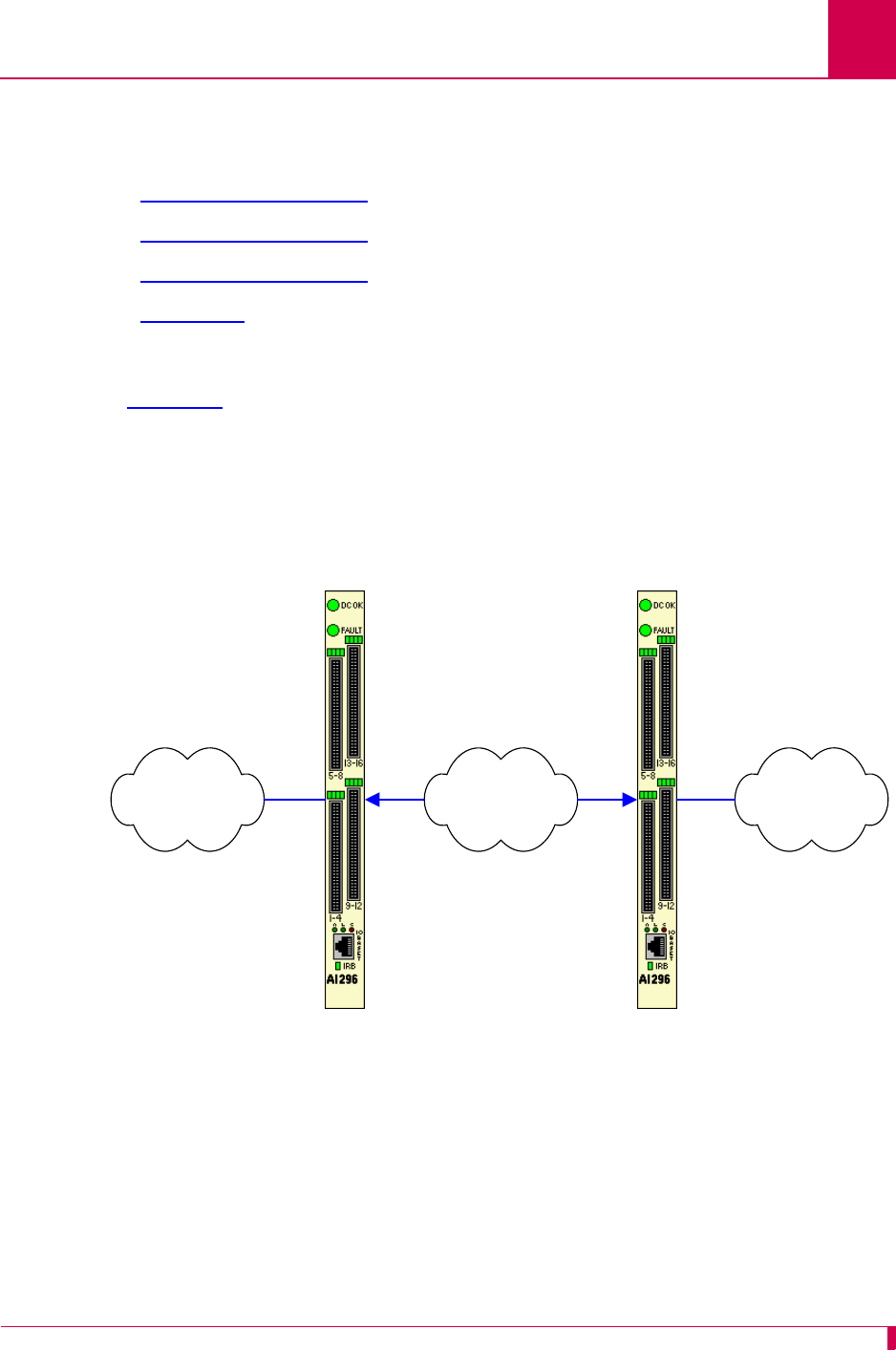
AI296 Version 9.8x User’s Guide
Alias and Call Routing Configuration: Alias Configuration Examples
8-45
Alias Configuration Examples
Examples are given for the following connections:
zSVC to SVC Connection
zSVC to PVC Connection
zPVC to SVC Connection
zMLT Route
SVC to SVC Connection
In Figure 8-2, the X.25 data on the incoming AI296 is on baseport 16, link 2 and has a
called address of 6145551234. The call continues on the outgoing AI296 on baseport 32,
link 4 and called address 6145553897:
Figure 8-2 SVC to SVC Connection Diagram
TCP/IP Network X.25 NetworkX.25 Network
Baseport 16
Link 2
Baseport 32
Link 4
Called Address
6145553897
Called Address
6145551234
IP Address
172.16.1.111
AI296 Incoming AI296 Outgoing
Called Protocol
TL1

AI296 Version 9.8x User’s Guide
Alias and Call Routing Configuration: Alias Configuration Examples
8-46
This example displays the menu items used to configure the SVC to SVC connection:
>10 TL1
Menu 8
01 Alias name -------------------------------------------------------6145551234
02+SLC Routing
03 Destination ----------------------------------------------------172.16.1.111
04 Called address ---------------------------------------------X25.4.6145553897
05 This alias is visible in the destination menu-----------------------------NO
06 Link number is (1..16) -
07 Caller's address -
08 Call data -
09 App. string -
10 Called protocol ---------------------------------------------------------TL1
11 Caller's protocol -
12 Alternate routing alias -
16+Test macros
17 Show the first entry in the alias translation table
18 Show the next entry in the alias translation table
19+Delete the above alias translation entry
20 Save the changes made
21 Exit this menu with no changes
Enter item number and optional ",value" then push <CR> key
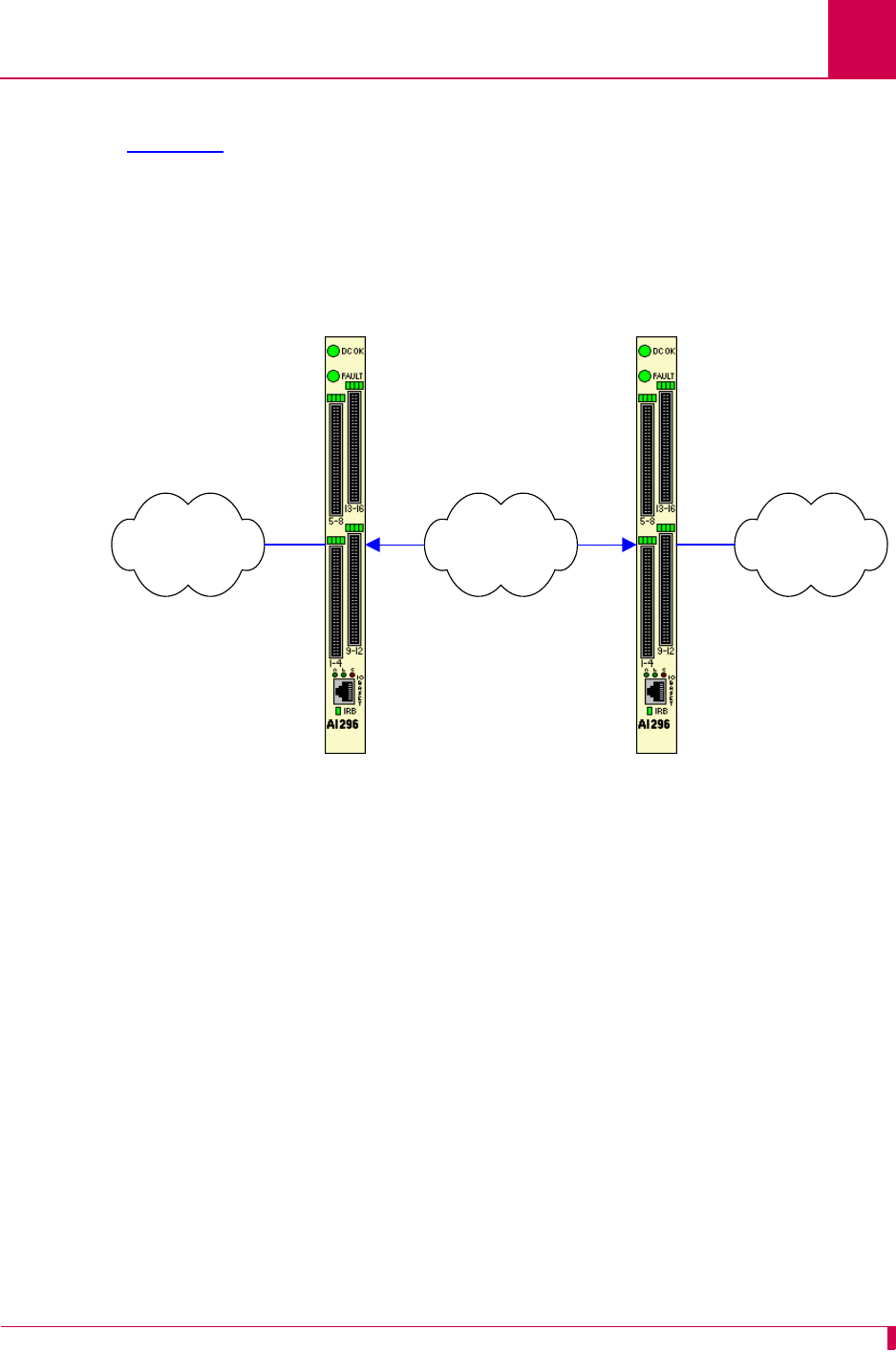
AI296 Version 9.8x User’s Guide
Alias and Call Routing Configuration: Alias Configuration Examples
8-47
SVC to PVC Connection
In Figure 8-3, the X.25 data on the incoming AI296 is on baseport 16, link 2 with a
called address of 6145551234. The call continues on the outgoing AI296 on baseport 32,
link 1:
Figure 8-3 SVC to PVC Connection Diagram
TCP/IP Network X.25 NetworkX.25 Network
Baseport 16
Link 2
LCN 3
Baseport 32
Link 1
LCN 4
Called Address
6145551234
IP Address
172.16.1.111
AI296 Incoming AI296 Outgoing
Called Protocol
TL1

AI296 Version 9.8x User’s Guide
Alias and Call Routing Configuration: Alias Configuration Examples
8-48
This example displays the menu items used to configure an SVC to PVC connection:
Note: Refer to Alias Configuration Examples on page 8-45 for a descriptions of all
menu items in this example.
>10 TL1
Menu 8
01 Alias name -------------------------------------------------------6145551234
02+SLC Routing
03 Destination ----------------------------------------------------172.16.1.111
04 Called address ----------------------------------------------------------PVC
05 This alias is visible in the destination menu-----------------------------NO
06 Link number is (1..16) -
07 Caller's address -
08 Call data -----------------------------------------------------------X25.1.4
09 App. string -
10 Called protocol ---------------------------------------------------------TL1
11 Caller's protocol -
12 Alternate routing alias -
16+Test macros
17 Show the first entry in the alias translation table
18 Show the next entry in the alias translation table
19+Delete the above alias translation entry
20 Save the changes made
21 Exit this menu with no changes
Enter item number and optional ",value" then push <CR> key

AI296 Version 9.8x User’s Guide
Alias and Call Routing Configuration: Alias Configuration Examples
8-49
PVC to SVC Connection
In Figure 8-4, the incoming X.25 data on the incoming AI296 is on baseport 16, link 2
with the alias of 16.X25.2.3. The call then continues out the outgoing AI296 on baseport
32 and called address 6145553897:
Figure 8-4 PVC to SVC Connection Diagram
TCP/IP Network X.25 NetworkX.25 Network
Baseport 16
Link 2
Baseport 32
Link 4
Called Address 6145553897
Alias 16.X25.2.3
IP Address 172.16.1.111
AI296 Incoming AI296 Outgoing
Called Protocol
TL1

AI296 Version 9.8x User’s Guide
Alias and Call Routing Configuration: Alias Configuration Examples
8-50
This example displays the menu items used to configure a PVC to SVC connection.
Note: Refer to Alias Configuration Examples on page 8-45 for a descriptions of all
menu items in this example.
>10 TL1
Menu 8
01 Alias name -------------------------------------------------------16.X25.2.3
02+SLC Routing
03 Destination ----------------------------------------------------172.16.1.111
04 Called address ---------------------------------------------X25.4.6145553897
05 This alias is visible in the destination menu-----------------------------NO
06 Link number is (1..16) -
07 Caller's address -
08 Call data -
09 App. string -
10 Called protocol ---------------------------------------------------------TL1
11 Caller's protocol -
12 Alternate routing alias -
16+Test macros
17 Show the first entry in the alias translation table
18 Show the next entry in the alias translation table
19+Delete the above alias translation entry
20 Save the changes made
21 Exit this menu with no changes
Enter item number and optional ",value" then push <CR> key
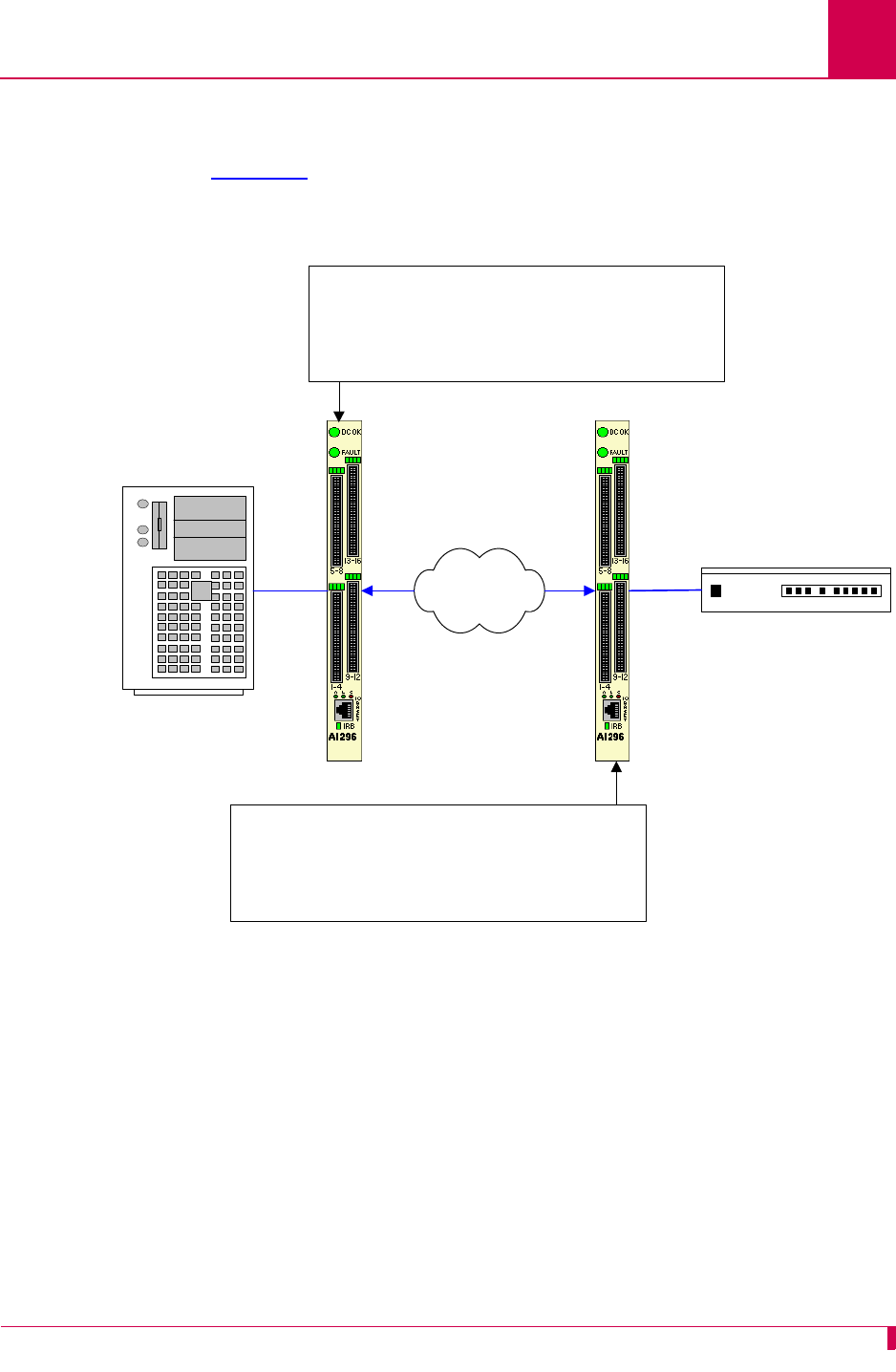
AI296 Version 9.8x User’s Guide
Alias and Call Routing Configuration: Alias Configuration Examples
8-51
MLT Route
You can use aliases to route MLT call information through a TCP/IP network. The
example in Figure 8-5 shows how aliases can be set up to route an MLT call. One
alias is configured for an AI296 card that is connected to the host and the other is
configured for an AI296 card that is connected to an NE.
Figure 8-5 MLT Call Routing Example
NE
MLT Host
TCP/IP Network
AI296 AI296
Link 3 Link 6
Alias Name: Called Address
Example: MLT:3
Called Address: Destination IP Address
Example: 192.168.1.140#1001
Called Protocol: AEPN -L
Alias Name: ip_address#tcp_port_number
Example: 192.168.1.140#1001
Caller’s Address:MLT:link_number
Example: MLT:6
Caller’s Protocol:AEPN -L

AI296 Version 9.8x User’s Guide
Alias and Call Routing Configuration: Alias Configuration Examples
8-52
This example displays the menu items used to configure the MLT host alias shown in
Figure 8-5 on page 8-51.
This example displays the menu items used to configure the MLT network element
alias shown in Figure 8-5 on page 8-51.
10,AEPN -L
Menu 8
01 Alias name ------------------------------------------------------------MLT:3
02+Simple alias translation
03 Destination -
04 Called address -------------------------------------------192.168.1.140#1001
05 This alias is visible in the destination menu-----------------------------NO
06 Link number is (1..16) -
07 Caller's address -
08 Call data -
09 App. string -
10 Called protocol -----------------------------------------------------AEPN -L
11 Caller's protocol -
12 Alternate routing alias -
14+Test macros
15 Show entire alias
16 Show the first entry in the alias translation table
17 Show the previous entry in the alias translation table
18 Show the next entry in the alias translation table
19+Delete the above alias translation entry
20 Save the changes made (20b: to the beginning, 20e: to the end)
21 Exit this menu with no changes
Enter item number and optional ",value" then push <CR> key
>
>11 AEPN -L
Menu 8
01 Alias name -----------------------------------------------192.168.1.140#1001
02+Simple alias translation
03 Destination -
04 Called address -
05 This alias is visible in the destination menu-----------------------------NO
06 Link number is (1..16) -
07 Caller's address ------------------------------------------------------MLT:6
08 Call data -
09 App. string -
10 Called protocol -
11 Caller's protocol ---------------------------------------------------AEPN -L
12 Alternate routing alias -
14+Test macros
15 Show entire alias
16 Show the first entry in the alias translation table
17 Show the previous entry in the alias translation table
18 Show the next entry in the alias translation table
19+Delete the above alias translation entry
20 Save the changes made (20b: to the beginning, 20e: to the end)
21 Exit this menu with no changes
Enter item number and optional ",value" then push <CR> key
>
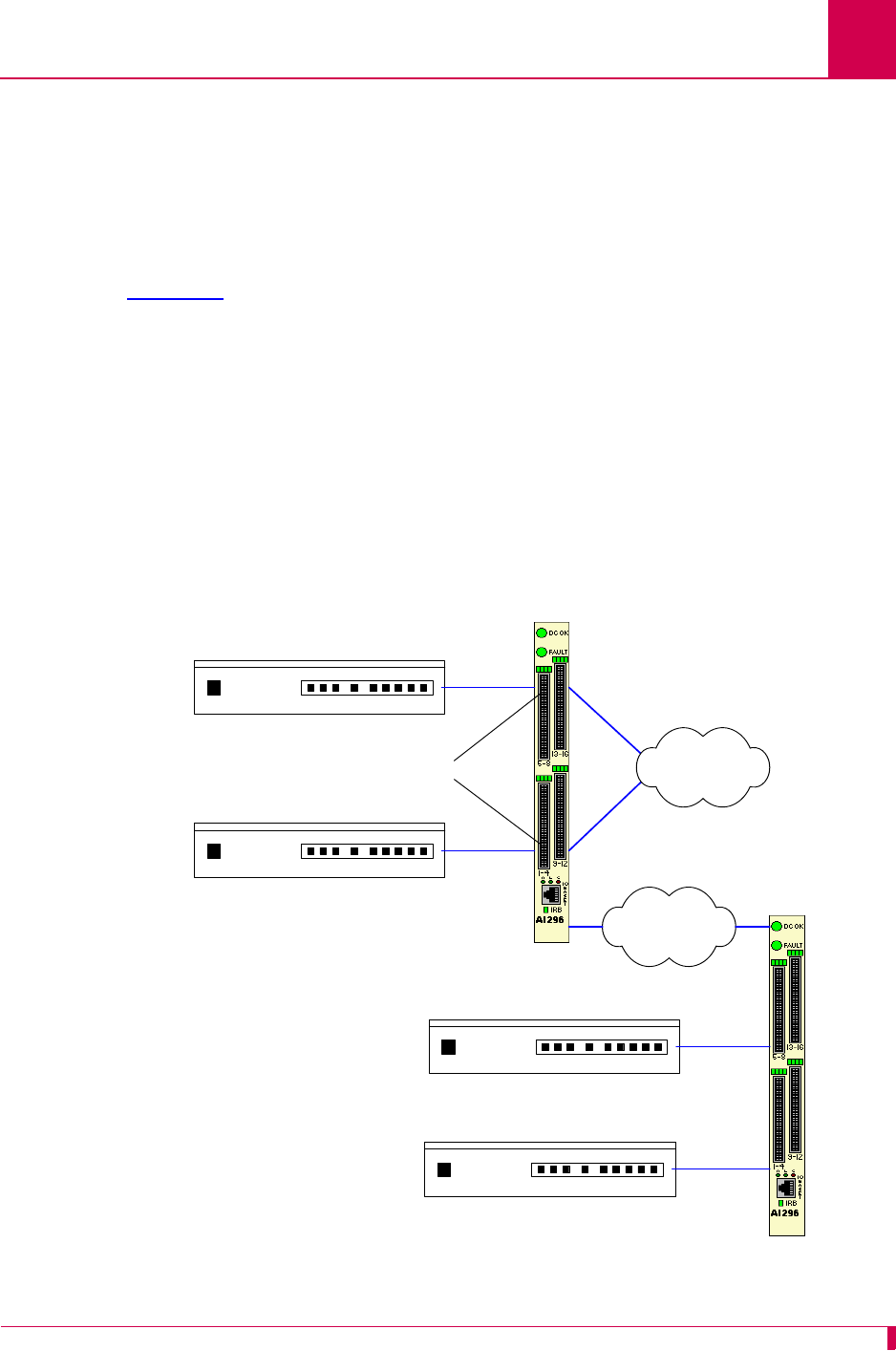
AI296 Version 9.8x User’s Guide
Alias and Call Routing Configuration: Alias Configuration Examples
8-53
Link-to-Link Call Routing
Link-to-link call routing lets users route all SVC calls coming in on one X.25 link to
another X.25 link. By using X.25 link-to-link call routing, it is now possible to create a
default route for all calls from a specified X.25 link. The alias for the default link-to-link
route can route all calls destined for the same link. On previous versions of AI296,
users had to create an alias for each unique called address.
In Figure 8-6, NE1 and NE2 place calls to NE3, NE4, and other elements on the X.25
network. Aliases route calls from NE1 and NE2 to the network elements. A link-to-link
call route exists between links 1 and 2, and between links 3 and 4. An incoming X.25
SVC call from NE1 that does not match an alias in the table would be routed to link 2,
and an incoming X.25 SVC call from NE2 that does not match an alias in the table
would be routed to to link 4.
Important: The link-to-link call alias must be at the end of the alias list. If the
link-to-link alias is above an actual destination alias, an X.25 SVC call
will be processed by the default link-to-link alias.
Figure 8-6 Link-to-Link Routing Example
NE 1
NE 2
IP Network
NE 3
NE 4
X.25 Packet
Network
AI296
AI296
Link 2
Link 4
Link-to-Link Calls
Link 1
Link 3

AI296 Version 9.8x User’s Guide
Alias and Call Routing Configuration: Alias Configuration Examples
8-54
This example displays AI296 configured to listen for all SVC calls on links 1 and 3 and
route those calls to links 2 and 4 (as displayed in Figure 8-6 on page 8-53).
Alias Edit Menu
Alias Name . . . . . ............................................. X25.1.SVC
Destination . . . . .......................................................
Caller's Address . . .......................................................
Called Address . . . ............................................... X25LL.2
Call Data . . . . . .......................................................
Caller's Protocol . .......................................................
Called Protocol . . .......................................................
Application String . .......................................................
Alternate Route . . .......................................................
Description . . . . .......................................................
Display Alias in Destination Menu . . . . . . . . . . . . . . [Yes] No
Alias Location . . . . . . . . . . . . . . . . . . . Beginning [End]
+ Alias Test Menu
<F1> Help <F2> Send <F4> Close <Ctrl-R> Return to Main Menu
Alias Edit Menu
Alias Name . . . . . ............................................. X25.3.SVC
Destination . . . . .......................................................
Caller's Address . . .......................................................
Called Address . . . ............................................... X25LL.4
Call Data . . . . . .......................................................
Caller's Protocol . .......................................................
Called Protocol . . .......................................................
Application String . .......................................................
Alternate Route . . .......................................................
Description . . . . .......................................................
Display Alias in Destination Menu . . . . . . . . . . . . . . [Yes] No
Alias Location . . . . . . . . . . . . . . . . . . . Beginning [End]
+ Alias Test Menu
<F1> Help <F2> Send <F4> Close <Ctrl-R> Return to Main Menu


AI296 Version 9.8x User’s Guide
AI296 Commands: Commands Overview
9-2
Commands Overview
AI296 is configurable directly through the local system using shell commands or
through AI198 using winslc commands and the menu system.
Shell Commands
Shell commands offer some of the same functionality available in the AI296 local
menu system, including:
zCreating, modifying, or deleting users and passwords
zAccessing the AI296 menu
zConfiguring PVCs
zMonitoring performance and diagnostic information
zPinging an IP address
zSetting up an ARP table
zSetting the trace level.
Shell Connections
Before using the shell commands, a shell connection to AI296 must be established.
You can connect locally using an asynchronous port on the AI296 front panel or
remotely using a Telnet connection.
Establishing a Local Shell Connection
Establish a local shell connection to AI296 through any port configured as a login port.
(By default, all ports are configured as login ports, but only port 1 is enabled.)
1. Use a PC or laptop with terminal emulation software such as HyperTerminal to
connect to AI296. For information on operating your particular terminal emulation
software, refer to the documentation provided with the program.
2. Set up your terminal emulation software to connect using COM port 1 (COM1).
3. Configure COM port 1 with the following parameters:
zBits per second: 9600
zData bits: 8
zParity: None
zStop bits: 1
zFlow control: None
4. From within your terminal emulation software, press ENTER to request a login
prompt.

AI296 Version 9.8x User’s Guide
AI296 Commands: Commands Overview
9-3
5. At the login prompt, enter your user name.
6. At the password prompt, enter your password.
Notes: ai is the default user name and password. AI296 allows only five logins
using the default password. On the sixth login, AI296 will prompt you to
change the default password to a new password.
Keep a copy of your username and password in a safe place. If you lose
or forget your password on AI296 in standalone mode, you must call
Kentrox customer service for assistance in gaining access to the card.
The destination menu appears.
7. Enter ai.
Establishing a Remote Shell Connection
Establish a remote shell connection to AI296 using AI198 command telnet or using
another Telnet client. To establish a Telnet session:
1. Use a PC or laptop with terminal emulation software such as HyperTerminal to
connect to AI296. For information on operating your particular terminal emulation
software, refer to the documentation provided with the program.
2. For user name, enter ai.
3. For password, enter ai. The destination menu appears.
4. For destination, enter ai. The [296] prompt appears.

AI296 Version 9.8x User’s Guide
AI296 Commands: winslc Commands
9-4
winslc Commands
The winslc commands let the user communicate with AI296 from AI198. Use these
commands to enter data, diagnose problems, and retrieve information from AI296.
Displaying winslc Command Logging
To monitor winslc commands, press CTRL+l when logged into AI198 to turn on
logging.
Using winslc Commands
To use winslc commands, the user must be logged into AI198 to receive output from
AI296. AI198 relays the command to AI296, which processes the command and
sends the result to the system log port (as configured in AI198 Menu 1.1). Valid winslc
commands are:
From the AI198, you can view the available winslc commands by entering the
following command:
winslc
baseport
help
where
baseport
specifies the baseport number of AI296.
Log/Alarm Message Header
To obtain output from winslc commands, enable the activity/alarm log (AI198 Menu
1.1, menu item 01*The activity and alarm log is turned). The first line of the response
for most winslc commands shows the following standard log/alarm message header:
zarp zpvcedit
zbreak zpvclist
zcreset zshow
zdiag-tconn zstaeia
zhelp zstaslc
zlink ztcpoutconn
zlinkstat ztrace
zpanic zupdate
zping zxvc
>@AI19807:42:26 081104 Sev=F Base=016 Msg:

AI296 Version 9.8x User’s Guide
AI296 Commands: winslc Commands
9-5
Table 9-1 describes the Log/Alarm message header elements.
Table 9-1 Log/Alarm Message Header Elements
Header Element Description
@AI198 Specifies the node name for the device that is producing the
log/alarm message (in this case, AI198).
7:42:26 Specifies the current time.
081104 Specifies the current date.
Sev=F Specifies the message severity level.
Base=016 Specifies the line card baseport number.
Msg Introduces the log/alarm message.

AI296 Version 9.8x User’s Guide
AI296 Commands: aaa
9-6
aaa
Description
These commands configure TACACS+ accounting, authentication, and authorization
settings.
Command Type
shell
Formats
aaa
account { disable | enable }
authen { disable | enable } [ all | async | telnet | ftp ]
author { priv-lvl | command }
chpass
fallback { disable | enable }
ppp authen {
link_range
| * } { disable | enable | fallback }
profile {
priv_range
} {
profile_name
| default }
retry {
retry_count
| default }
stat [ clear ]
summary
timeout {
timeout_value
| default }
Parameters
account Enables or disables TACACS+ accounting of user login events and
shell command events. An accounting start packet or stop packet is
issued each time a user logs into or out of AI296. An accounting start
packet is also issued for each shell command that is run.
Note: If enabled, accounting is performed for all shell connection
types (Async, Telnet, and FTP), even if authentication is
disabled. For information about authentication, refer to
command aaa authen.
The following parameters are accepted:
zdisable—Disables TACACS+ accounting.
zenable—Enables TACACS+ accounting.

AI296 Version 9.8x User’s Guide
AI296 Commands: aaa
9-7
authen Enables or disables TACACS+ authentication for AI296 command shell
access. TACACS+ authentication may be enabled on all connections,
or on a connection type basis. By default, TACACS+ authentication is
disabled on all connection types. The following parameters are
accepted:
zall—Enables or disables TACACS+ authentication on all
connection types.
Note: If no connection type is specified, all is automatically
selected.
zasync—Enables or disables TACACS+ authentication on
asynchronous link connections.
zdisable—Disables TACACS+ authentication.
zenable—Enables TACACS+ authentication.
zftp—Enables or disables TACACS+ authentication on FTP
connections.
ztelnet—Enables or disables TACACS+ authentication on Telnet
connections.
author Configures the TACACS+ authorization method for the AI296 shell.
The authorization method can be either privilege level or
per-command. Privilege level authorization is based on the priv-lvl
returned from the TACACS+ server. Per-command authorization
requires AI296 to contact the TACACS+ server for each shell command
run by a user. Individual commands are then allowed or denied.
Note: Authorization is performed only on the connection types that
have enabled authentication. For information about enabling
authentication, refer to command aaa authen.
The following parameters are accepted:
zcommand—Configures the TACACS+ authorization method that
requires to contact the TACACS+ server for each shell command
run by a user. Individual commands are then allowed or denied.
zpriv-lvl—Configures the TACACS+ authorization method based
on the priv-lvl returned from the TACACS+ server.
chpass Changes the current user’s password on the TACACS+ server.
Note: The TACACS+ server may not support, or be configured to
support, password changes.

AI296 Version 9.8x User’s Guide
AI296 Commands: aaa
9-8
fallback Enables or disables TACACS+ fallback for shell access. If TACACS+
fallback is enabled and attempts to contact all configured TACACS+
servers fail, then AI296’s user database is used for authentication and
authorization. The AI296 local log file is used for accounting. The
following parameters are accepted:
zdisable—Disables TACACS+ fallback.
zenable—Enables TACACS+ fallback.
ppp
authen Enables or disables TACACS+ authentication and sets the fallback
mode for specified AsyncPPP links.
Note: The link type must be set to AsyncPPP for this command to
have any effect.
The following parameters are accepted:
z*—Specifies all links.
zdisable—Disables TACACS+ authentication.
zenable—Enables TACACS+ authentication.
zfallback—Enables TACACS+ authentication with fallback.
z
link_range
—Defines a link or range of links. Valid values are 1 to
16. Individual values are separated by commas (,) and hyphens (-).
For example, 1,4-6 specifies links 1, 4, 5, and 6.

AI296 Version 9.8x User’s Guide
AI296 Commands: aaa
9-9
profile Associates a custom profile with a privilege level or range of privilege
levels. The following rules apply:
zTACACS+ privilege levels range from 0 to 15.
zCustom profiles can be associated with privilege levels 2 through
14.
zPrivilege levels 2 through 14 default to the management system
profile.
zPrivilege levels 0, 1, and 15 are reserved for the Status,
Management, and Supervisor system profiles (respectively).
Note: For information on creating custom profiles, refer to command
profile on page 9-76.
Privilege levels are used only if the authorization method is set to
priv-lvl. The only exception to this occurs under all of the following
conditions:
1. The authentication server returns a privilege level.
2. The authorization server cannot be reached.
3. The authorization is set to per-command and fallback is enabled.
Note: For information on configuring the authorization method, refer
to command aaa author.
The following parameters are accepted:
zdefault—Removes the association between a range of privilege
levels and a profile.
z
priv_range
—Defines the range of privilege levels that will be
associated with the profile. Individual values are separated by
commas (,) and hyphens (-). For example, 1,4-6 specifies privilege
levels 1, 4, 5, and 6.
z
profile_name
—Specifies the name of an existing profile.
retry Configures the number of consecutive connection attempts that are
made to a TACACS+ server before the attempt fails. Consecutive
attempts are only made if the TACACS+ server responds but refuses a
connection. If no response is received from a TACACS+ server before
the configured timeout period, then no further connection attempts are
made. For information on configuring the timeout period, refer to
command aaa on page 9-6.
The following parameters are accepted:
z
retry_count
—Defines the number of consecutive connection
attempts that are made. Valid values are 1 to 100.
zdefault—Resets the number of connection attempts to the default
value.

AI296 Version 9.8x User’s Guide
AI296 Commands: aaa
9-10
Command Defaults
Disabled TACACS+ accounting, authenitcation, and authorization
Examples
The following AAA settings are configured:
zEnabled TACACS+ fallback
zEnabled AAA accounting
zEnabled AAA authentication on telnet connections
zpriv-lvl authorization
zCustom profile newProf with TACACS+ privilege levels 3 to 5
zEnabled TACACS+ authentication for AsyncPPP links 1 to 9
z10 retry attempts
z15 second timeout.
stat Displays or clears AAA specific counters and statistics. The following
parameter is accepted:
clear—Clears all counters and statistics.
summary Displays a summary of all authentication, authorization, and accounting
settings.
timeout Configures the number of seconds to wait for a response from a
TACACS+ server. If no response is received from the server in the
allowed number of seconds, the connection attempt fails. The following
parameters are accepted:
z
timeout_value
—Defines how long (in seconds) AI296 will wait for
a response from a TACACS+ server when a connection attempt is
made. Valid values are 1 to 120.
zdefault—Resets the timeout value to its default.
[296] aaa fallback enable
[296] aaa account enable
[296] aaa authen enable telnet
WARNING: Potential lock-out:
At least one TACACS+ server must be enabled for Authentication
AND at least one TACACS+ server must be enabled for Authorization.
[296] aaa author priv-lvl
[296] aaa profile 3-5 newProf
[296] aaa ppp authen 1-9 enable
[296] aaa retry 10
[296] aaa timeout 15
[296]

AI296 Version 9.8x User’s Guide
AI296 Commands: aaa
9-11
This example displays a summary of all authentication, authorization, and accounting
settings.
This example displays all AAA specific counters and statistics.
This example displays a successful password change on a TACACS+ server.
[296] aaa summary
Async Shell Access: Local
Telnet Shell Access: AAA
FTP Access: Local
Authorization: Priv-lvl
Accounting: Enabled
Fallback: Enabled
AAA Timeout: 15 seconds
AAA Retry Count: 10
Priv-lvl 3: newProf
Priv-lvl 4: newProf
Priv-lvl 5: newProf
[296]
[296] aaa stats
AAA Statistics
--------------
Authentication Attempts: 0
Authentication Failures: 0
Authentication Fallbacks: 0
Authorization Attempts: 0
Authorization Failures: 0
Authorization Fallbacks: 0
Accounting Attempts: 16
Accounting Failures: 0
Accounting Fallbacks: 16
[296]
[296] aaa chpass
Old Password:
New Password:
Re-enter New password:
Password Changed
Password Change was successful
[296]

AI296 Version 9.8x User’s Guide
AI296 Commands: alarm
9-12
alarm
Description
This command:
zDisplays a list of the alarm groups and the overall alarm severity
zDisplays alarms for a specified alarm group or for a specified range of severity
levels within an alarm group
zDisplays alarms by severity level or for a specified range of severity levels
zClears all non-self-clearing alarm groups and the overall alarm severity
zClears a specified non-self-clearing alarm group
zMasks a specified alarm group
zUnmasks a specified alarm group.
Command Type
shell
Formats
alarm
group
[
range
]
-sev [
range
]
-clear [
group
]
-mask
group
-unmask
group
Parameters
group
Defines the group of alarms to display, clear, mask, or unmask. Valid
values are existing alarm groups. The following parameters is accepted:
range
—Defines a range of alarm severity levels to display. Valid
values are 1 to 32. Individual values in the range are separated by
hyphens (-).
-sev Displays all alarms or a range of alarms based severity level. The
following parameters is accepted:
range
—Defines a range of alarm severity levels to display. Valid
values are 1 to 32. Individual values in the range are separated by
hyphens (-).

AI296 Version 9.8x User’s Guide
AI296 Commands: alarm
9-13
Examples
This example displays a list of the alarm groups and the overall alarm severity.
-clear Clears all non-self-clearing alarm groups or a specified non-self-clearing
alarm group.
Note: Only non-self-clearing alarm groups can be manually cleared.
Self-clearing alarms clear themselves when the problem that
caused the alarm is resolved.
The following parameter is accepted:
group
—Defines the group of alarms to display, clear, mask, or
unmask. Valid values are existing alarm groups.
-mask Prevents a specified alarm group from affecting overall alarm severity.
The following parameter is accepted:
group
—Defines the group of alarms to display, clear, mask, or
unmask. Valid values are existing alarm groups.
-unmask Allows a specified alarm group to affect overall alarm severity. The
following parameter is accepted:
group
—Defines the group of alarms to display, clear, mask, or
unmask. Valid values are existing alarm groups.
[296]alarm
Alarm Group Sev Date & Time Message (most recent, most severe in group)
----------- --- ----------- ----------------------------------------------
*general 0 00-00 00:00
links 0 06-01 00:00 Link 1 up.
----------- --- ----------- ----------------------------------------------
*not self-clearing () masked
Overall alarm severity: 0
[296]

AI296 Version 9.8x User’s Guide
AI296 Commands: alarm
9-14
This example displays all system alarms in group links.
This example displays alarms for links 5-8 in group links.
This example displays all alarms by severity level.
[296]alarm links
Num Sev Date & Time Message
--- --- ----------- ----------------------------------------------
1 0 06-01 00:00 Link 1 up.
2 0 06-01 00:00 Link 2 down.
3 0 06-01 00:00 Link 3 down.
4 0 06-01 00:00 Link 4 down.
5 0 06-01 00:00 Link 5 down.
6 0 06-01 00:00 Link 6 down.
7 0 06-01 00:00 Link 7 down.
8 0 06-01 00:00 Link 8 down.
9 0 06-01 00:00 Link 9 down.
10 0 06-01 00:00 Link 10 down.
11 0 06-01 00:00 Link 11 down.
12 0 06-01 00:00 Link 12 down.
13 0 06-01 00:00 Link 13 down.
14 0 06-01 00:00 Link 14 down.
15 0 06-01 00:00 Link 15 down.
16 0 06-01 00:00 Link 16 down.
--- --- ----------- ----------------------------------------------
'links' alarm group severity: 0
[296]
[296]alarm links 5-8
Num Sev Date & Time Message
--- --- ----------- ----------------------------------------------
5 0 06-01 00:00 Link 5 down.
6 0 06-01 00:00 Link 6 down.
7 0 06-01 00:00 Link 7 down.
8 0 06-01 00:00 Link 8 down.
--- --- ----------- ----------------------------------------------
'links' alarm group severity: 0
[296]
[296]alarm -sev
Alarm Group Num Sev Date & Time Message
----------- --- --- ----------- ----------------------------------------------
links 1 4 06-13 14:40 Link 1 is enabled but has not come up.
links 5 4 06-13 14:40 Link 5 is enabled but has not come up.
links 10 4 06-13 14:40 Link 10 is enabled but has not come up.
links 12 4 06-13 14:40 Link 12 is enabled but has not come up.
general 1 6 06-13 14:40 Unable to find auto ID name of 222 board
----------- --- --- ----------- ----------------------------------------------
( ) masked
[296]

AI296 Version 9.8x User’s Guide
AI296 Commands: alarm
9-15
This example displays all alarms that have a severity level between 4 and 7.
This example displays the clearing of all non-self-clearing alarm groups.
This example displays the clearing of non-self-clearing alarm group general.
This example displays the prevention of alarm group links from affecting the overall
alarm severity.
This example displays the unmasking of alarm group links.
[296]alarm -sev 4-7
Alarm Group Num Sev Date & Time Message
----------- --- --- ----------- ----------------------------------------------
links 1 4 06-13 14:40 Link 1 is enabled but has not come up.
links 5 4 06-13 14:40 Link 5 is enabled but has not come up.
links 10 4 06-13 14:40 Link 10 is enabled but has not come up.
links 12 4 06-13 14:40 Link 12 is enabled but has not come up.
general 1 6 06-13 14:40 Unable to find auto ID name of 222 board
----------- --- --- ----------- ----------------------------------------------
( ) masked
[296]
[296]alarm -clear
Alarm groups cleared.
Overall alarm severity set to 0.
[296]
[296]alarm -clear general
Alarm group cleared.
[296]
[296]alarm -mask links
Alarm group masked.
[296]
[296]alarm -unmask links
Alarm group unmasked.
[296]

AI296 Version 9.8x User’s Guide
AI296 Commands: arp
9-16
arp
Description
This command displays, deletes, or adds entries in the ARP cache.
Command Types
shell and winslc
Formats
For the shell:
arp
-a [
ip_address
]
-d
ip_address
-s
ip_address
mac_address
For the winslc command:
winslc
baseport
arp
-a [
ip_address
]
-d
ip_address
-s
ip_address
mac_address
Parameters
-a Displays all entries in the ARP cache table or just the
ip_address
entry.
The following parameter is accepted:
ip_address
—Defines the IP address of the destination device in
dotted decimal format.
baseport
Defines the baseport number for AI296.
-d Deletes an entry from the ARP cache table. The following parameter is
accepted:
ip_address
—Defines the IP address of the destination device in
dotted decimal format.
-s Adds a permanent entry to the ARP cache for the current session.
Permanent entries must be in the same subnetwork as the IP address
of the destination device. The following parameters are accepted:
z
ip_address
—Defines the IP address of the destination device in
dotted decimal format.
z
mac_address
—Defines the MAC address of the destination device.

AI296 Version 9.8x User’s Guide
AI296 Commands: arp
9-17
Examples
This example displays all ARP cache entries.
This example displays an ARP cache entry with IP address 10.40.5.20.
This example displays the configuration of an ARP cache entry with IP address
10.40.53.2 and MAC address 08-00-09-4a-c5-5a.
[296] arp -a
Internet Address Ethernet Address Type Life
172.16.52.16 00-00-92-90-F2-D9 temp 5 mins
172.16.2.9 00-40-72-00-7F-96 temp 2 mins
[296]
Column Description
Internet Address Displays the IP address of the destination device.
Ethernet Address Displays the MAC address of the destination device.
Type Displays the type of ARP cache entry as perm or temp. Type temp
specifies that the entry is temporary and will be deleted when the
time interval specified in the Life column expires. Type perm
specifies that the entry was entered by the user with the -s
option. This entry will not expire and can be removed using the
-d delete option.
Note: Resetting AI296 clears both permanent and temporary
entries.
Life Displays the time interval for which the temporary entry will
remain in the ARP cache.
[296]arp -a 10.40.5.20
Internet Address Ethernet Address Type Life
10.40.5.20 00-01-02-EE-A8-30 temp 4 mins
[296]
[296]arp -s 10.40.53.2 08-00-09-4a-c5-5a
10.40.53.2 mapped to Ethernet address 08-00-09-4A-C5-5A
[296]

AI296 Version 9.8x User’s Guide
AI296 Commands: arp
9-18
This example displays the deletion of an ARP cache entry with IP address 10.40.53.2.
[296]arp -d 10.40.53.2
Mapping for 10.40.53.2 deleted
[296]

AI296 Version 9.8x User’s Guide
AI296 Commands: break
9-19
break
Description
This command terminates an asynchronous or shell connection. Use command diag-
tconn on page 9-49 (not command who on page 9-122) when referencing
connections and connection ID numbers.
Note: This command only works for calls connected to the shell.
CAUTION: This command operates without regard to current activity on the serial
port.
Command Types
shell and winslc
Formats
For the shell command:
break {
link_number
|
connection_origin
}
break -id
id_number
For the winslc command:
winslc
baseport
break {
link_number
|
connection_origin
}
winslc
baseport
break -id
id_number
Parameters
connection_origin
Defines the IP address and port number of the device
connection being terminated.
baseport
Defines the baseport number for AI296.
id_number
Defines the ID number of the device connection being
terminated.
link_number
Defines the link number for the connection being terminated.

AI296 Version 9.8x User’s Guide
AI296 Commands: break
9-20
Examples
This example displays the termination of a shell connection for a device with IP
address 10.40.5.11 and port number 1821.
This example displays the termination of a connection for a device with ID 65.
[296]break 10.40.5.11#1821
Breaking connection: 10.40.5.11#1821
[296]
[296]break -id 65
Breaking connection with ID: 65
[296]

AI296 Version 9.8x User’s Guide
AI296 Commands: bridge
9-21
bridge
Description
This command dumps a list of all the addresses in the bridge table or clears the
bridge table.
Command Types
shell
Formats
bridge { dump | clear }
Parameters
Examples
This example displays the dumping of the bridge table.
dump Dumps a list of all the addresses in the bridge table.
clear Clears the bridge table.
[296]bridge dump
Hash table for Bridge Group 0:
MAC Address Source Interface
00:00:92:90:CF:42 Ethernet
00:00:92:90:CD:42 Ethernet
00:40:72:00:D2:43 Link 16
00:60:47:CC:DB:43 Ethernet
00:00:92:90:CF:44 Ethernet
00:A0:C9:25:9A:B1 Ethernet
00:40:72:00:73:B8 Ethernet
00:40:72:00:41:C7 Ethernet
00:00:92:90:95:C8 Ethernet
00:00:92:90:C7:CE Ethernet
00:10:4B:64:25:CF Ethernet
00:00:92:90:0C:D0 Ethernet
00:00:92:9B:58:D3 Ethernet
00:00:92:B6:3A:D5 Ethernet
00:00:0E:3A:02:D5 Ethernet
00:10:83:F5:A5:D8 Ethernet
00:00:92:90:96:DB Ethernet
00:00:92:90:95:DF Ethernet
00:40:72:00:AF:E7 Link 16

AI296 Version 9.8x User’s Guide
AI296 Commands: creset
9-22
creset
Description
This command resets the error counters for a link or a range of links. There is no
output for this command. To see if the error counters were reset for the links you
specified, enter command staslc on page 9-92.
Command Types
shell and winslc
Formats
For the shell command:
creset
range
For the winslc command:
winslc
baseport
creset
range
Parameters
Examples
This example displays the resetting of error counters for links 5 to 7.
range
Defines the link or a range of links being reset. Valid values are:
zA single link number (for example, 3 to reset error counters for link
3)
zA series of link numbers separated by commas (for example, 1,2,3
to reset error counters for links 1, 2, and 3)
zA range of link numbers separated by a dash (for example, 1-2 to
reset error counters for links 1 and 2)
zAny combination of a single link number, series, and/or range (for
example, 1,2-3 to reset error counters for links 1, 2, and 3)
z* to reset error counters for all links.
baseport
Defines the baseport number for AI296.
[296]creset 5-7
[296]

AI296 Version 9.8x User’s Guide
AI296 Commands: date
9-23
date
Description
This command sets and displays the date and the time for AI296 when it is operating
in standalone mode.
Command Types
shell
Formats
date
Examples
This example displays the configuration of date 08-04-2005 and time 10:24:49 for AI296
in standalone mode.
[296]date
Today is Thursday 05-01-2004 01:09:52
Please enter the date and/or time.
Use 'MM-DD-YYYY' and/or 'hh:mm:ss' (24-hour format): 08-04-2004 10:24:49
[296]

AI296 Version 9.8x User’s Guide
AI296 Commands: debug
9-24
debug
Description
This command enables or disables the logging of debugging data.
Tip: You have to have logging turned on to view debug information from a shell
connection.
Command Type
shell
Formats
debug { alias | x25 | pvcfsm | asypvcfsm | nlipvcfsm | tpifsm |
modmuxfsm | allfsm | pppfsm | linkChange | bootp | all } { on | off }
Parameters
alias Enables or disables the logging of alias translation debugging data.
x25 Used primarily by Kentrox Technical Support to isolate system faults.
pvcfsm Used primarily by Kentrox Technical Support to isolate system faults.
asypvcfsm Used primarily by Kentrox Technical Support to isolate system faults.
nlipvcfsm Used primarily by Kentrox Technical Support to isolate system faults.
tpifsm Used primarily by Kentrox Technical Support to isolate system faults.
modmuxfsm Used primarily by Kentrox Technical Support to isolate system faults.
allfsm Used primarily by Kentrox Technical Support to isolate system faults.
pppfsm Used primarily by Kentrox Technical Support to isolate system faults.
bootp Enables or disables the logging of bootp attempts so that users can
determine if the bootp process is still underway or if it has been
completed.
linkChange Enables or disables the logging of debugging data when the PPP
protocol on a link has gone down.
all Enables or disables the logging of all debugging data.
on Enables the logging of specified debugging data.
off Disables the logging of specified debugging data.

AI296 Version 9.8x User’s Guide
AI296 Commands: debug
9-25
Examples
This example displays the enabling of all debug data logging.
[296]debug all on
debug alias is on
debug x25 is on
debug pvcfsm is on
debug asypvcfsm is on
debug nlipvcfsm is on
debug tpifsm is on
debug modmuxfsm is on
debug allfsm is on
debug pppfsm is on
debug linkChange is on
debug mltfsm is on
debug bootp is on
[296]

AI296 Version 9.8x User’s Guide
AI296 Commands: delete
9-26
delete
Description
This command deletes a specified file that resides on AI296.
Command Type
shell
Formats
delete
filename
Parameters
Examples
This example displays the deletion of file log.txt.
filename
Defines the name of the file to delete.
[296]delete log.txt
Are you sure you want to delete 'log.txt'? (y/n) y
log.txt deleted.
[296]

AI296 Version 9.8x User’s Guide
AI296 Commands: diag-conn
9-27
diag-conn
Description
This command displays a list of enabled links along with connection information for
each link. Data can be displayed continuously, one page at a time, or sent to the
screen one time only for all connections. The default mode is a continuous display.
Command Type
shell
Formats
diag-conn
Examples
This example displays existing connections across AI296.
Note: For explanations of the states shown, such as idle and data transfer, refer to
section pvclist on page 9-80.
C O N N E C T I O N S Mode: Continuous [Search Inactive]
103. ASY.1.1 [ Idle ]
113. TCP 172.16.2.9#1032 <--Data Transfer--> SHELL
Enter S-kip, I-nternal, A-ll, M-ore, D-etail, F-ind, P-revPg, N-extPg or Q-uit:
Display Item Description
S-kip This option bypasses connections. It gives a prompt for the number
of connections to skip.
I-nternal This option toggles between I-nternal and H-ide Int. I-nternal
displays all the internal loopback connections along with other
connections.
A-ll This option displays all connections without page breaks. The
display does not show duplicate connections. For example, if
connection number 15 is connected to 30, the connection from 30
to 15 will not appear.
M-ore This option toggles between M-ore and L-ess. It displays the link and
PVC number for X.25 PVCs, the link and X.121 addresses for X.25
SVCs, and the alias used to make the connection.

AI296 Version 9.8x User’s Guide
AI296 Commands: diag-conn
9-28
D-etail This option prompts for the ID of the connection to view and
displays details for that connection.
F-ind This option displays specific types of connections. F-ind indicates
text matches that are applied to the display lines. The matching is
not case-sensitive. The logic for the matches can be AND or OR.
PATTERN 1, LOGIC 2, and PATTERN 3 are evaluated before
LOGIC 4 and PATTERN 5 are considered.
P-revPg This option displays the previous page of connections. Twenty
connections per page appear. The numbers that appear in front of
the description (for example, 103. and 113.) are relative numbers
and do not represent any particular link, port, or PVC. The display
does not show duplicate connections. For example, if connection
number 15 is connected to 30, the connection from 30 to 15 will not
appear.
N-extPg This option displays the next page of connections. Twenty
connections per page appear. The numbers that appear in front of
the description (for example, 103. and 113.) are relative numbers
and do not represent any particular link, port, or PVC. The display
does not show duplicate connections. For example, if connection
15 is connected to 30, the connection from 30 to 15 will not appear.
Q-uit This option exits the command display and returns the user to the
prompt.
Display Item Description

AI296 Version 9.8x User’s Guide
AI296 Commands: diag-eth
9-29
diag-eth
Description
This command monitors and displays Ethernet diagnostic information.
Using Interpretation Mode
There are three levels of diagnostic information:
zMinimum—Displays minimal diagnostic information (mostly the packet’s source
and destination). This is the default interpretation mode setting.
zMedium—Displays protocol fields that are likely to change for each packet, as
well as those with values that are out of the ordinary.
zMaximum—Displays all protocol fields.
To configure interpretation mode:
1. At the prompt, enter diag-eth.
2. Enter interpret minimum, interpret medium, interpret maximum, or
interpret.
Tip: Entering interpret with no additional parameter toggles interpretation off
and on. When interpretation is toggled from off to on, the diagnostic level is
set to the minimum level (the default).
Using the Timestamp Option
Timestamps can be configured to appear on the diagnostic display. The timestamp
value displays the calendar date and time.
To enable or disable timestamp display:
1. At the prompt, enter diag-eth.
2. Enter timestamp to toggle between enabling and disabling the display of the
timestamp.
Using Promiscuous Mode
Promiscuous mode can be enabled or disabled during Ethernet diagnostic sessions.
By disabling promiscuous mode, only packets traveling on the network that are
destined for your Ethernet card appear. By enabling promiscuous mode, all the
packets traveling on the network appear.
To enable and disable promiscuous mode:
1. At the prompt, enter diag-eth.
2. Enter promiscuous to toggle between enabling and disabling promiscuous mode.

AI296 Version 9.8x User’s Guide
AI296 Commands: diag-eth
9-30
Note: Operating AI296 in the promiscuous mode can reduce performance. The
default setting is disabled promiscuous mode. AI296 automatically returns
to the default setting (promiscuous mode disabled) when the user quits
the diag-eth command.
Using the Help Option
To obtain command help:
1. At the prompt, enter diag-eth.
2. Enter help. The diag-eth help screen appears.
Configuring Filters
While using the diag-eth command, various filters can be defined to display specific
or general diagnostic information.
Tip: There is help associated with the filter command. To view this help, enter
filter after you enter diag-eth. The filter help screen appears.
Important: If you are connecting to AI296 using Telnet, remember to filter out the
traffic associated with the telnet connection. Failure to do so can cause
the diagnostic program to become overloaded, which makes AI296
unresponsive.
To configure a filter:
1. At the prompt, enter diag-eth.
2. Enter the desired filter. Refer to section Formats on page 9-31 for information on
filter formats.
Capturing Data
While using the diag-eth command, data can be captured for Ethernet diagnostics.
All variables and filters can be configured for specific or general information capture.
To configure data capture:
1. Define the following settings:
zInterpretation Mode
zTimestamp Mode
zPromiscuous Mode
zData Mode
zFilters

AI296 Version 9.8x User’s Guide
AI296 Commands: diag-eth
9-31
2. Enter go. The system starts capturing data with the user-defined settings and
filters.
3. Enter stop to stop capturing data.
Exiting the diag-eth Session
To exit the diag-eth session, type quit. The [296] prompt appears.
Command Type
shell
Formats
diag-eth
The following formats apply to filters:
filter { add | delete } [ src
mac_address
] [ dst
mac_address
]
filter { add | delete } [ src
ip_address
] [ dst
ip_address
]
filter { add | delete } [ src
ip_address
#
port_number
]
[ dst
ip_address
#
port_number
]
filter { add | delete } [ src *#
port_number
] [ dst *#
port_number
]
filter { add | delete } protocol [ ip | tcp | udp | icmp | arp | osi ]
filter { add | delete } all
filter list
Parameters
add Adds a filter.
delete Deletes a filter.
src Defines the source address (MAC, IP, or TCP/UDP)
for the filter being created.
mac_address
Defines the MAC address to use for either the source
or destination of the filter being created.
dst Defines the destination address (MAC, IP, or
TCP/UDP) for the filter being created.
ip_address
Defines the IP address to use for either the source or
destination of the filter being created.
ip_address
#
port_number
Defines the IP address and the TCP/UDP port number
for either the source or destination of the filter being
created.

AI296 Version 9.8x User’s Guide
AI296 Commands: diag-eth
9-32
Examples
This example displays the configuration of diagnostic interpretation level medium for the
Ethernet diagnostic session display.
This example displays the enabling and disabling of the timestamp display.
This example displays the enabling and disabling of promiscuous mode.
*#
port_number
Defines the TCP/UDP port number regardless of the
MAC/IP address settings.
protocol Adds or deletes a specific protocol filter. Available
protocol filters are:
zip
ztcp
zudp
zicmp
zarp
zosi.
all Deletes all the filters or adds a filter to show all
Ethernet traffic.
list Lists all the filters in the system.
[296]diag-eth
interpret medium
Interpretation is now set to MEDIUM.
[296]diag-eth
timestamp
Timestamps will now be displayed.
timestamp
Timestamps will no longer be displayed.
[296]diag-eth
promiscuous
The ethernet chip is now in promiscuous mode.
promiscuous
The ethernet chip is now in normal mode.

AI296 Version 9.8x User’s Guide
AI296 Commands: diag-eth
9-33
This example displays Ethernet diagnostic help information.
This example displays the help associated with the Ethernet diagnostic filter
command.
[296]diag-eth
help
Commands for diag-eth:
interpret Turn on data interpretation.
quit Exit diag-eth.
help Display this help text.
data Toggle uninterpreted data display.
timestamp Toggle data timestamping.
go Begin data capturing.
stop Terminate data capturing.
filter Add a data filter.
promiscuous Toggle promiscuous mode for the ethernet chip.
[296]diag-eth
filter
Usage: FILTER <ADD|DELETE> [SRC <mac>] [DST <mac>]
FILTER <ADD|DELETE> [SRC <ipAddr>] [DST <ipAddr>]
FILTER <ADD|DELETE> [SRC <ipAddr#port>] [DST <ipAddr#port>]
FILTER <ADD|DELETE> [SRC <*#port>] [DST <*#port>]
FILTER <ADD|DELETE> PROTOCOL <IP|TCP|UDP|ICMP|ARP|OSI>
FILTER <ADD|DELETE> ALL
FILTER LIST
Where:
<mac> is the MAC address desired, with the format
XX:XX:XX:XX:XX:XX, with each 'X' representing
a hexidecimal digit.
<ipAddr> is the desired IP address, with the format
X.X.X.X, where 0 < X < 256.
<port> is the desired TCP port.

AI296 Version 9.8x User’s Guide
AI296 Commands: diag-eth
9-34
This example displays the diagnostic Ethernet display when the following parameters
are entered:
zinterpret max to set maximum interpretation
ztimestamp to enable timestamping
zpromiscuous to enable promiscuous mode
zfilter add src 172.16.2.9 to add a filter for address 172.16.2.9
zdata to display data
zgo to start the data capture
zstop to stop capturing data.
[296]diag-eth
interpret max
Interpretation is now set to MAXIMUM.
timestamp
Timestamps will now be displayed.
promiscuous
The ethernet chip is now in promiscuous mode.
filter add src 172.16.2.9
New filter added.
data
Uninterpreted data will now be displayed.
go
----------------------------------------------------------------------
Timestamp: 11-10-2006 02:33:54.74
<- Ethernet: [ 00:40:72:00:7F:96 ] -> [ 00:00:0C:7E:F2:72 ]
Protocol [ 0x0800:IP ]
IP: [ 172.16.2.9 ] -> [ 172.16.0.1 ]
Version [ 4 ]
Header Length [ 20 bytes ]
Type-Of-Service [ none ]
Identifier [ 37903 ]
Fragmentation Flags [ none ] Offset [ 0 bytes ]
Time-To-Live [ 60 hops ]
Protocol [ 0x01:ICMP ]
ICMP: Type [ 8 ] Code [ 0 ]
(echo request)
00 00 48 44 41 42 43 44 45 46 47 48 49 4A 4B 4C ..HDABCDEFGHIJKL
4D 4E 4F 50 51 52 53 54 55 56 57 58 59 5A 41 42 MNOPQRSTUVWXYZAB
43 44 45 46 47 48 49 4A 4B 4C 4D 4E 4F 50 51 52 CDEFGHIJKLMNOPQR
53 54 55 56 57 58 59 5A 41 42 43 44 45 46 47 48 STUVWXYZABCDEFGH
49 4A 4B 4C IJKL
----------------------------------------------------------------------
stop

AI296 Version 9.8x User’s Guide
AI296 Commands: diag-eth
9-35
This example displays the diagnostic Ethernet display when the following is entered:
zfilter add src 00:40:72:00:d2:d9 to configure a filter with source MAC address
00:40:72:00:d2:d9
zfilter add dst 00:40:72:00:d2:d9 to configure a filter with destination MAC
address 00:40:72:00:d2:d9
zgo to start the capture
zstop to end the capture.
This example displays the diagnostic Ethernet display when the following is entered:
zfilter add protocol tcp to configure a filter with a defined TCP protocol
zgo to start the capture
zstop to end the capture.
[296]diag-eth
filter add src 00:40:72:00:d2:d9
New filter added.
filter add dst 00:40:72:00:d2:d9
New filter added.
go
----------------------------------------------------------------------
<- 01 80 C2 00 00 00 00 40 72 00 D2 D9 00 26 42 42 .......@r....&BB
03 00 00 00 00 81 00 20 00 40 72 00 D2 D9 00 00 ....... .@r.....
00 00 00 20 00 40 72 00 D2 D9 80 65 00 00 07 00 ... .@r....e....
09 00 0F 00 00 00 00 00 00 00 00 00 ............
----------------------------------------------------------------------
<- 00 40 72 00 D2 D9 00 40 72 00 7F 96 08 00 45 00 .@r....@r.....E.
00 29 0F 81 00 00 3C 06 F4 8A AC 10 02 09 AC 10 .)....<.........
20 9A 04 16 00 17 75 87 E4 2F 30 E0 B6 B4 50 10 .....u../0...P.
08 00 A6 96 00 00 41 0D 01 B4 6D 74 01 B4 FF FC ......A...mt....
----------------------------------------------------------------------
<- stop
[296]diag-eth
filter add protocol tcp
New filter added.
go
----------------------------------------------------------------------
<- 00 A0 C9 22 D8 C4 00 00 92 B6 2F 97 08 00 45 2C ..."....../...E,
00 6C CF B7 40 00 80 06 69 4B AC 10 37 14 AC 10 .l..@...iK..7...
32 28 10 9A 00 8B 01 67 55 24 00 D0 5D 81 50 18 2(.....gU$..].P.
1E 59 5C 61 00 00 00 00 00 40 FF 53 4D 42 2B 00 .Y\a.....@.SMB+.
00 00 00 18 03 80 00 00 00 00 00 00 00 00 00 00 ................
00 00 07 08 FE CA 02 10 41 0F 01 01 00 1B 00 4C ........A......L
57 4F 20 43 57 20 56 4C 4F 20 44 45 4F 20 4D 41 WO CW VLO DEO MA
57 20 4C 4D 57 20 41 52 57 00 W LMW ARW.
----------------------------------------------------------------------
stop

AI296 Version 9.8x User’s Guide
AI296 Commands: diag-eth
9-36
This example displays the diagnostic Ethernet display when filter list is entered to
display all filters.
This example displays the deletion of filter protocol tcp.
This example displays the deletion of all filters.
[296]diag-eth
filter list
Filters currently being used by diag-eth:
protocol tcp
dst 00:40:72:00:d2:d9
src 00:40:72:00:d2:d9
dst 172.16.2.9
src 172.16.2.9
protocol tcp
[296]diag-eth
filter delete protocol tcp
Filter 'protocol tcp' has been deleted.
[296]diag-eth
filter delete all
Filter 'dst 00:40:72:00:d2:d9' has been deleted.
Filter 'src 00:40:72:00:d2:d9' has been deleted.
Filter 'dst 172.16.2.9' has been deleted.
Filter 'src 172.16.2.9' has been deleted.

AI296 Version 9.8x User’s Guide
AI296 Commands: diag-info
9-37
diag-info
Description
This command displays diagnostic information for WAN, asynchronous, Ethernet, and
TCP connections as well as for memory. Different screens of information can be
viewed depending on the command option that is entered. The screens display the
state of serial links and system updates once per second. The available display
options are W, M, A, E, and T. They display the following information:
zOption W displays WAN diagnostic information. W is the default display.
zOption M displays the STREAMS allocation and memory information.
zOption A displays asynchronous information.
zOption E displays Ethernet information.
zOption T displays TCP data.
Note: Type X to exit the command display.
Command Type
shell
Formats
diag-info

AI296 Version 9.8x User’s Guide
AI296 Commands: diag-info
9-38
Examples
This example displays the WAN Diag Info screen, which is accessed by typing W.
This example displays diagnostic information for STREAMS allocation and memory,
which are accessed by typing M.
W A N D I A G I N F O
LINK STATE TX_PEND RX_WANT NO_BUF BYTE_IN BYTE_OUT
1 30 0 1 0 0 759050
2 0 0 1 0 0 0
3 0 0 1 0 0 0
4 0 0 1 0 0 0
5 0 0 1 0 0 0
6 0 0 1 0 0 0
7 0 0 1 0 0 0
8 0 0 1 0 0 0
9 0 0 1 0 0 0
10 0 0 1 0 0 0
11 0 0 1 0 0 0
12 0 0 1 0 0 0
13 0 0 1 0 0 0
14 0 0 1 0 0 0
15 0 0 1 0 0 0
16 0 0 1 0 0 0
Enter W-an, M-emory, A-sync, E-thernet, T-cp or Q-uit:
Column Description
LINK Displays the link number.
STATE Displays the state of the WAN driver. Two states are available:
z0 means the X.25 frame level is not established.
z30 means the X.25 frame level is established.
TX_PEND Displays the state of the transaction if one is pending for transmission.
RX_WANT Displays the state of the buffer if another buffer is needed.
NO_BUF Displays the number of times the receiver cannot be started because no
buffers were available.
BYTE_IN Displays the count of the number of bytes coming in.
BYTE_OUT Displays the count of the number of bytes going out.

AI296 Version 9.8x User’s Guide
AI296 Commands: diag-info
9-39
S T R E A M S A L L O C A T I O N
NAME FREE ALLOC %FREE USED FAIL HWM
Queues 8361 239 97 1073 0 241
Streams 2085 115 94 532 0 116
Bufcalls 64 0 100 0 0 0
Timeouts 2387 13 99 402908 0 45
Message blocks 16015 369 97 588495 0 551
Data blocks:
Class 0 1519 17 98 7954 0 40
Class 1 4080 16 99 835 0 18
Class 2 14944 56 99 301866 0 64
Class 3 9981 19 99 11034 0 32
Class 4 500 0 100 0 0 0
Class 5 390 260 60 222746 0 263
Class 6 1 1 50 1 0 1
Extended 350 0 100 0 0 0
S Y S T E M A L L O C A T I O N (alloc failed=0)
REGION: ASIZ CNT CNT_HWM USED USED_HWM UNIT_SIZE
AI1 741664 324 424 17632 20704 32
AI2 741664 0 0 0 0 32
AI3 741664 32 36 179296 180832 32
Enter M-emory, A-sync, E-thernet, T-cp or Q-uit:
Column Description
NAME Displays the name of the STREAMS resource.
FREE Displays the number of free or available STREAMS resources.
ALLOC Displays the number of STREAMS resources allocated at the time of
the display.
%FREE Displays the percent of free or available STREAMS resources.
USED Displays the number of STREAMS resources used since the card was
last rebooted.
FAIL Displays the number of times an allocation failed.
HWM Displays the highest number of resources ever allocated at one time.
REGION Displays the memory allocation regions.
ASIZ Displays the size of the memory allocation regions in bytes.
CNT Displays the number of blocks allocated from a region (regardless of
size).
CNT_HWM Displays the highest number of blocks allocated since the card was last
rebooted.
USED Displays the number of bytes currently allocated from a region.

AI296 Version 9.8x User’s Guide
AI296 Commands: diag-info
9-40
This example displays diagnostic information for asynchronous connections, which is
accessed by typing A.
USED_HWM Displays the highest number of bytes allocated since the card was last
rebooted.
UNIT_SIZE Displays the size in bytes of the memory units that can be allocated.
ASYNC DIAG INFO
LINK STATE BYTES_IN BYTES_OUT LINK STATE BYTES_IN BYTES_OUT
1 1 0 0 16 0 0 0
2 1 0 0 17 0 0 0
3 1 0 0 18 0 0 0
4 0 0 0 19 0 0 0
5 0 0 0 20 0 0 0
6 0 0 0 21 0 0 0
7 0 0 0 22 0 0 0
8 0 0 0 23 0 0 0
9 0 0 0 24 0 0 0
10 0 0 0 25 0 0 0
11 0 0 0 26 0 0 0
12 0 0 0 27 0 0 0
13 0 0 0 28 0 0 0
14 0 0 0 29 0 0 0
15 0 0 0 30 0 0 0
16 0 0 0 31 0 0 0
17 0 0 0 32 0 0 0
Enter M-emory, A-sync, E-thernet, T-cp or Q-uit:
Column Description
LINK Displays the link number.
STATE Displays the state of the driver. Two states are available:
z0 specifies that the link is not established.
z1 specifies that the link is enabled. The link does not have to have a
connection to be enabled.
BYTE_IN Displays the number of bytes coming into the link.
BYTE_OUT Displays the number of bytes going out of the link.
Column Description

AI296 Version 9.8x User’s Guide
AI296 Commands: diag-info
9-41
This example displays diagnostic information for the front panel Ethernet interface,
which is accessed by typing E.
ETHERNET 0
Rx LG frame length violation: ---0
Rx NO nonoctet aligned frame: ---0
Rx SH short frame (runt): -------0
Rx CR CRC error: ----------------0
Rx OV overrun: ------------------0
Rx CL collision: ----------------0
Rx BSY buffers exhausted: -------0
Rx frames missed: ---------------0
Rx frames received: -------------0
Rx bytes received: --------------0
Tx RL retry limit exceeded: -----0
Tx RC collisions: ---------------0
Tx UN underruns: ----------------0
Tx LC late collisions:-----------0
Tx CSL carrier sense lost: ------2451095
Tx queued buffers: --------------0
Tx frames sent: -----------------2451095
Tx bytes sent: ------------------233814304
Unexpected interrupts: ----------0
Enter M-emory, A-sync, E-thernet, T-cp or Q-uit:
Display Item Description
Rx LG frame length violation Displays the number of frame length violations in
received packets.
Rx NO nonoctet aligned frame Displays the number of misaligned, received frames.
Rx SH short frame (runt) Displays the number of short received frames.
Rx CR CRC error Displays the number of packets received that have
had CRC errors.
Rx OV overrun Displays the number of packets not received by the
interface because of a receiver overrun.
Rx CL collision Displays the transmit collisions on received frames.
This is the number of times the Ethernet device goes
to transmit but cannot because someone else is
already transmitting.
Rx BSY buffers exhausted Displays the number of times all receive buffers
were used, but more were required.
Rx frames missed Displays the number of frames that were supposed
to be received, but were missed.

AI296 Version 9.8x User’s Guide
AI296 Commands: diag-info
9-42
Rx frames received Displays the number of frames received on the
connection.
Rx bytes received Displays the number of bytes received on the
connection.
Tx RL retry limit exceeded Displays the number of times transmitted frames
exceeded the retry limit.
Tx RC collisions Displays the number of transmit collisions. This is
the number of times the Ethernet device goes to
transmit but cannot because someone else is
already transmitting.
Tx UN underruns This displays the number of times the transmitter
has run out of data due to the system being busy.
Tx LC late collisions Displays the number of late collisions on transmitted
frames.
Tx CSL carrier sense lost Displays the number of times that the carrier sense
was lost.
Tx queued buffers Displays the number of queued buffers.
Tx frames sent Displays the number of frames that were
transmitted.
Tx bytes sent Displays the number of bytes that were transmitted.
Unexpected interrupts Displays the number of times that the transfer of
frames was unexpectedly interrupted.
Display Item Description

AI296 Version 9.8x User’s Guide
AI296 Commands: diag-info
9-43
This example displays diagnostic information for the Ethernet sonic chip in use on this
card (SONIC0), which is accessed by typing E.
SONIC0
frames_received 2133706 2451073
bytes_received 204088549 233809600
frames_sent 317511
bytes_sent 38293966 0
collisions 116 0
transmit_errors 0 0
crc_errors 0 0
alignment_errors 0 0
missed_packets 0 0
rx_buffers_exhausted 0 0
heartbeatlost 0 0
rx_overruns 0 0
rba_exceeded 0 0
current_tda 8
ex_defers 0 0
ex_coll 0 0
tx_underruns 0 0
bad_tx_size 0 0
tx_blocked 0 2451086
tx_delayed 0 0
state 2 2451086
eth intr stuck: 0----------------233812081
Display Item Description
frames_received Displays the number of frames received on the connection.
bytes_received Displays the number of bytes received on the connection.
Note: This field displays a negative number after it reaches
a count of 2,147,483,647. This is normal operation
and does not indicate an error.
frames_sent Displays the number of frames sent from the connection.
bytes_sent Displays the number of bytes sent from the connection.
Note: This field displays a negative number after it reaches
a count of 2,147,483,647. This is normal operation
and does not indicate an error.
collisions Displays the number of transmit collisions. This is the
number of times the Ethernet device goes to transmit but
cannot because someone else is already transmitting.
transmit_errors Displays the number of transmit errors that have occurred.

AI296 Version 9.8x User’s Guide
AI296 Commands: diag-info
9-44
crc_errors Displays the number of packets received that have had CRC
errors.
alignment_errors Displays the number of alignment errors.
missed_packets Displays the number of missed packets.
rx_buffers_exhausted Displays the number of times all receive buffers were used,
but more were required.
heartbeatlost Displays if there is an error between the Ethernet interface
and the Ethernet transceiver.
rx_overruns Displays the number of packets not received by the interface
because of a receiver overrun.
rba_exceeded Displays the number of times that the maximum number of
receive buffers have been exceeded.
current_tda Displays the current data area being transmitted.
ex_defers Displays the number of times that the maximum limit on the
excessive deferral timer is exceeded. An excessive deferral
error is recorded when the following events occur:
zA transmission attempt is made while another node is
transmitting.
zThe transmit period is longer than the excessive deferral
timer limit.
ex_coll Displays the number of times an excessive collision has
been recorded. An excessive collision is recorded when a
transmit attempt occurs 16 times and a collision occurs each
time.
tx_underruns Displays the number of times the transmitter has run out of
data due to the system being busy.
bad_tx_size Displays the number of times the transmit byte count was
incorrect.
tx_blocked Displays a 1 if the transmitter is blocked. Otherwise, a 0 is
displayed.
tx_delayed Displays the number of times the transmitter has been
blocked.
Display Item Description

AI296 Version 9.8x User’s Guide
AI296 Commands: diag-info
9-45
This example displays diagnostic information for TCP data, which is accessed by
typing T.
state Displays the current state of the Ethernet interface. The
following values may appear:
z0—The Ethernet interface is uninitialized.
z1—The Ethernet interface is idle.
z2—The Ethernet interface is active.
z3—The Ethernet interface needs to be reset.
eth intr stuck Displays the number of times the Ethernet interface interrupt
has stuck while servicing the interrupt.
T C P / I P I N F O
Copied ethernet receive packet: 0
TCP keepalive failed: 0
TCP max keepalive tries: 1
Dropped SNMP request: 0
Enter M-emory, A-sync, E-thernet, T-cp or Q-uit:
Display Item Description
Copied ethernet receive packet: Displays the number of copied Ethernet receive
packets.
TCP keepalive failed: Displays the number of TCP keep-alive
messages that have been sent and were
expected to be received, but were not received.
TCP max keepalive tries: Displays the maximum number of TCP keep-alive
messages received on the connection.
Dropped SNMP request: Displays the number of dropped SNMP requests.
Display Item Description

AI296 Version 9.8x User’s Guide
AI296 Commands: diag-line
9-46
diag-line
Description
This command monitors incoming and outgoing asynchronous traffic and displays
diagnostic information for the traffic. A help screen provides a list of commands
available for line monitoring diagnostics.
CAUTION: The line monitor degrades the performance of AI296. Do not use this
command in heavy traffic situations in which performance is crucial.
Note: Information from the line monitor diagnostic mode only appears when data is
passed on serial links. If no data is passed, the screen is blank.
Table 9-2 displays the line monitor mode options that can be entered after diag-line
is entered.
Table 9-2 Line Monitor Mode Options
Option Function
data Toggles the display of data on or off.
modem Toggles the display of modem signals on or off.
tToggles the display of a timestamp for each frame of data
displayed on or off.
h or rHides (h) or reveals (r) all lines on AI296.
h lx or r lx Hides (h) or reveals (r) a specified line (
x
).
r l
x y
Reveals a specified LCN (
y
) on a specified line (
x
).
r l
x y z
Reveals a range of specified LCNs (
y
through
z
) on a
specified line (
x
).
h l
x
y
- or r l
x
y
- Hides or reveals all LCNs from a specified LCN (
y
) on up on a
specified line (
x
).
h l
x
-
y
or r l
x
-
y
Hides or reveals all LCNs from 0 to a specified LCN (
y
) on a
specified line (
x
).
filterL2 Toggles the filtering of level 2 frames without packet
information on or off.

AI296 Version 9.8x User’s Guide
AI296 Commands: diag-line
9-47
Tip: Press ENTER to execute a command and press ESC to end the diagnostic
session.
CAUTION: If you are connected to AI296 through a serial port, do not monitor the
port with command diag-line. Use command hide to hide and not
monitor the port. Failure to comply with this statement can cause AI296
to become unresponsive.
Command Type
shell
Formats
diag-line
interpret [ a | x ] Toggles the display of decoded packet data on the line
monitor on or off and optionally selects the format of the data
in the data portion of the packet (a or x).
za displays the data in the data portion of the packet in
ASCII/hexadecimal format. Unprintable data
(hexadecimal values 0x00 to 0x20 and 0x7F to 0xFF)
appears as two digit hexadecimal numbers separated by
a space. Printable data appears as printable characters.
This option only applies to data.
zx displays all the data in the data portion of the packet in
hexadecimal format. All data appears as two-digit
hexadecimal numbers separated by a space. This option
only applies to data.
print Prints the range of revealed LCNs for all lines.
CTRL+sPauses the line monitor.
go or CTRL+qReactivates the line monitor after displaying the line monitor
options.
ESC or qQuits monitoring traffic, exits from the line monitor, and
returns to the prompt.
?Displays a list of the options available for line monitoring
diagnostics.
Table 9-2 Line Monitor Mode Options (Continued)
Option Function

AI296 Version 9.8x User’s Guide
AI296 Commands: diag-line
9-48
Examples
This example displays a typical default line monitor display for asynchronous data.
06>d FF 03 00 31 00 01 FF FF FF FF FF FF 00 00 92 9B ...1............
59 0C 08 06 00 01 08 00 06 04 00 01 00 00 92 9B Y...............
59 0C AC 10 32 05 00 00 00 00 00 00 AC 10 22 79 Y...2........."y
00 00 00 00 00 00 00 00 00 00 00 00 00 00 00 00 ................
00 00 ..
06<d FF 03 02 01 00 00 00 00 00 80 00 00 40 72 00 6F ............@r.o
77 00 00 00 00 80 00 00 40 72 00 6F 77 80 04 00 w.......@r.ow...
00 14 00 02 00 0F 00 .......
06>d FF 03 00 31 00 01 FF FF FF FF FF FF 00 10 4B D0 ...1..........K.
D3 5D 08 06 00 01 08 00 06 04 00 01 00 10 4B D0 .]............K.
D3 5D AC 10 33 D1 00 00 00 00 00 00 AC 10 20 EB .]..3......... .
00 00 00 00 00 00 00 00 00 00 00 00 00 00 00 00 ................
00 00 ..
06>d FF 03 00 31 00 01 FF FF FF FF FF FF 00 10 4B D0 ...1..........K.
D3 5D 08 06 00 01 08 00 06 04 00 01 00 10 4B D0 .]............K.
D3 5D AC 10 33 D1 00 00 00 00 00 00 AC 10 1E 82 .]..3...........
00 00 00 00 00 00 00 00 00 00 00 00 00 00 00 00 ................
00 00 ..
Column Description
Line number Displays the line number, which can range from 01 to 32.
Direction indicator Displays the direction indicator for the line. One of the
following appears:
z> for transmitted frames
z< for received frames.
Frame type indicator Displays the frame type indicator for the line. One of the
following appears:
zd for asynchronous links
zBlank for other frames or packets.
Data If the data field byte count is disabled, it gets displayed as
ct: <# of bytes in data field>. If the data display is enabled
and only present in data packets, then the data byte count is
displayed as <ASCII STRING>.

AI296 Version 9.8x User’s Guide
AI296 Commands: diag-tconn
9-49
diag-tconn
Description
This command displays a list of enabled links along with connection information for
each link. It displays all connections on AI296 in the same format as command diag-
conn on page 9-27, but it is not interactive.
Command Types
shell and winslc
Formats
For the shell command:
diag-tconn
For the winslc command:
winslc
baseport
diag-tconn
Parameters
Examples
This example displays active connections on AI296. This is a partial display. The rest
of the response follows the pattern below for the remaining connections.
Note: The connection ID is the first number that appears for each connection. For
example, the connection ID for connection PARENT2 is 1.
baseport
Defines the baseport number for AI296.
[296] diag-tconn
TIDMUXsw#1
13:26:30 040900 Sev=F Base=032 Msg:
AI232 Complete Connections Dump:
1. PARENT2 <-----> 32.ASY.2.1
3. TCP 172.16.31.45#5001 <-----> PARENT2.1
TID(s): SONEPLEX-NE3 SONEPLEX-NE4
15. TCP 192.168.31.15#5001 <-----> PARENT2.2
TID(s): NE4-DAYTON-OH NE5-DAYTON-OH NE6-DAYTON-OH
NE7-DAYTON-OH NE8-DAYTON-OH NE9-DAYTON-OH
[296]

AI296 Version 9.8x User’s Guide
AI296 Commands: dir
9-50
dir
Description
This command displays a list of files with associated times, dates, permissions, and
sizes.
Command Type
shell
Formats
dir [ -l ]
Parameters
Examples
This example displays all available files.
This example displays all available files with permission, size, time, and date
information.
-l Displays a list of the available files and file information such as permission,
time, date, and file size. The ls command with this option is the same as the
dir command.
[296]dir
boot.ini
boot.img
232.img
log.txt
primary.cnf
[296]
[296]dir -l
-rw-r--r-- 1 0 0 143 Jun 1 22:52 boot.ini
-r--r--r-- 1 0 0 2175720 Aug 15 09:54 boot.img
-rw-r--r-- 1 0 0 22061 Jun 1 00:00 log.txt
-rw-r--r-- 1 0 0 4342 Aug 15 08:21 core.txt
-rw-r--r-- 1 0 0 7092 Jun 13 22:46 primary.cnf
[296]

AI296 Version 9.8x User’s Guide
AI296 Commands: exit
9-51
exit
Description
This command ends the current shell session and returns to the login prompt.
Command Type
shell
Formats
exit
Examples
This example displays an exit from the current shell session.
[296]exit
Writing Configuration ...
Goodbye.
Valid destinations are as follows:
AI
Enter destination name (or "EXIT" to logout):
>

AI296 Version 9.8x User’s Guide
AI296 Commands: head
9-52
head
Description
This command displays the first few lines of a file.
Command Type
shell
Formats
head [ -n
lines
]
file_name
...
Parameters
Examples
This example displays the first 30 lines of file core.txt.
[ -n
lines
] Defines the number of lines to display. The default is 20.
file_name
Defines the name of the file to display.
Note: Several filenames can be entered with this command.
[296]head -n 30 core.txt
296 crash dump at 14:16:30, 07-20-2004 (up 0 days 00:31:46):
Version 96HPC960.000007 created on 2004-03-29 at 09:43:35
Crash Code= 000000ad
PC= 00000000 SP= 00000000 IMMR= 00000000 MSR= 00000000
GPR00= 00000000 GPR01= 00000000 GPR02= 00000000
GPR03= 00000000 GPR04= 00000000 GPR05= 00000000
GPR06= 00000000 GPR07= 00000000 GPR08= 00000000
GPR09= 00000000 GPR10= 00000000 GPR11= 00000000
GPR12= 00000000 GPR13= 00000000 GPR14= 00000000
GPR15= 00000000 GPR16= 00000000 GPR17= 00000000
GPR18= 00000000 GPR19= 00000000 GPR20= 00000000
GPR21= 00000000 GPR22= 00000000 GPR23= 00000000
GPR24= 00000000 GPR25= 00000000 GPR26= 00000000
GPR27= 00000000 GPR28= 00000000 GPR29= 00000000
GPR30= 00000000 GPR31= 00000000
CR= 00000000 SSR0= 00000000 SSR1= 00000000
LR= 00000000 XER= 00000000 CTR= 00000000
PVR= 00500000 PSOS1= 00000000 PSOS2= 00000000 PSOS3= 00000000
Stack dump: Caller
200082c0: 9421 ffc8 7c08 02a6 bea1 000c 9001 003c [see LR]
200082d0: 7c7f 1b78 3ae0 0000 4800 1419 7c76 1b78
200082e0: 56d6 001e 3b16 3e82 a338 0000 572c 043e
200082f0: 7d96 6214 3bcc 2004 82be 0000 7ebd ab78
20008300: 7fe3 fb78 4801 76bd 7c7c 1b78 578a 043e
20008310: 2c0a 0100 4081 0008 3b80 0100 3b60 0000
20008320: 576c 043e 578b 043e 7c0c 5800 4080 001c
[296]

AI296 Version 9.8x User’s Guide
AI296 Commands: help
9-53
help
Description
This command lists all available system commands or information for a specific
command.
Command Types
shell and winslc
Formats
For the shell command:
help [
command
]
For the winslc command:
winslc
baseport
help [
command
]
Parameters
Examples
This example displays a list of all available commands.
baseport
Defines the baseport number for AI296.
command
Defines the name of the command for which specific information will be
displayed.
[296]help
The following commands are available:
*ftplogin diag-tconn more staslc
*telnetlogin dir pad syncflash
alarm exit passwd tail
arp head ping tcpoutconn
break help pppstatus tftp
bridge id profile tftpboot
creset ip pvcedit trace
debug link pvclist type
delete linkstat reset useradd
diag-conn log sholog userdel
diag-eth logout show users
diag-info ls staeia who
diag-line menu standalone xvc
[296]

AI296 Version 9.8x User’s Guide
AI296 Commands: help
9-54
This example displays help information for command show.
[296]help show
Usage: show [perf | comments | conn | data | mem | tcp | wan | tconn |
pvc | eth | ip | router | version | log | crash | inventory |
ports]
[296]

AI296 Version 9.8x User’s Guide
AI296 Commands: id
9-55
id
Description
This command displays the current user name and profile.
Command Type
shell
Formats
id
Examples
This example displays the current user name and profile.
[296]id
Username: 'pubs'
Profile: 'supervisor'
[296]

AI296 Version 9.8x User’s Guide
AI296 Commands: ip
9-56
ip
Description
This command displays the following system settings:
zIP address
zSubnet mask
zHigh IP address
zPrimary router IP address
zBackup router IP address
Command Type
shell
Formats
ip
Examples
This example displays the configured IP address information.
[296]ip
IP Address Subnet Mask High IP Address
-------------------------------------------------------
010.040.057.015 255.255.000.000 010.040.057.015
Router IP Address
-------------------------
010.040.000.001 (Default)
No backup router
[296]

AI296 Version 9.8x User’s Guide
AI296 Commands: ip init
9-57
ip init
Note: This command is only valid when AI296 is in standalone mode.
Description
This command configures the following settings for AI296 in standalone mode:
zIP address
zSubnet mask
zHigh IP address
zPrimary gateway address
zBackup gateway address
zIP address range
CAUTION: The following message appears when the “ip init” command is invoked
and no login ports are configured:
There are no login ports currently configured for this system. Please take
necessary precautions to prevent lockout.
Command Type
shell
Formats
ip init
Examples
This example displays the prompt that appears when ip init is entered. A prompt
appears for each configurable IP address item.
[296] ip init
Enter IP Address (xxx.xxx.xxx.xxx):

AI296 Version 9.8x User’s Guide
AI296 Commands: ip init
9-58
This example displays the configuration of all the IP settings available with this
command:
[296] ip init
Enter IP Address (xxx.xxx.xxx.xxx):172.16.2.39
Setting IP Address to 172.16.2.39
Enter Subnet Mask (xxx.xxx.xxx.xxx):255.255.000.000
Setting Subnet Mask to 255.255.000.000
Enter Router Address (xxx.xxx.xxx.xxx):172.16.000.1
Setting Router Address to 172.16.000.1
Enter Backup Router Address (default none):172.16.2.41
Setting Backup Router Address to 172.16.2.41
Enter IP Address Range (default 1):
Setting range to 1
[296]

AI296 Version 9.8x User’s Guide
AI296 Commands: link
9-59
link
Description
This command is used to:
zForce a serial link to connect or disconnect
Note: When this command is used to disconnect a serial link, all calls are torn
down. The serial link does not come back online until command link
start is issued.
Important: If you are connected to the AI296 shell using a serial port, remember
not to disable that port or else loss of connectivity will result.
zRestart a link, which is a stop followed by a start
zShow a configuration summary for a link or range of links.
Command Types
shell and winslc
Formats
For the shell command:
link {
link_range
| * } { restart | start | stop }
For the winslc command:
winslc
baseport
link {
link_range
| * } { start | stop | restart }
Parameters
*Specifies all links.
baseport
Defines the baseport number for AI296.
link_range
Defines a link or range of links. Valid values are 1 to 32. Individual
values are separated by commas (,) and hyphens (-). For example,
1,4-6 specifies links 1, 4, 5, and 6.
Note: This parameter applies to any action the user is trying
perform (start, stop, restart, or show information).
restart Restarts the serial links.
start Enables the serial links.
stop Disables the serial links.

AI296 Version 9.8x User’s Guide
AI296 Commands: link
9-60
Examples
This example displays the starting of links 1 through 4 and 6.
This example displays the stopping of links 6 and 8.
[296]link 1-4,6 start
[296]
[296]link 6,8 stop
[296]

AI296 Version 9.8x User’s Guide
AI296 Commands: linkstat
9-61
linkstat
Description
This command displays link statistic information.
Command Types
shell and winslc
Formats
For the AI296 system command:
linkstat
For the winslc command:
winslc
baseport
linkstat
Parameters
baseport
Indicates the baseport number of AI296.

AI296 Version 9.8x User’s Guide
AI296 Commands: linkstat
9-62
Examples
This example displays the link statistic information for AI296.
[296]linkstat
E D R C D F P
Link N T T T C R K Speed Conn Rx/Pkt Rx/Bytes Tx/Pkt Tx/Bytes Rx
/CRC Rx/Abt Rx/Ovr Tx/Und Intf
A R S S D M T
1: +Asy + + - - 9600,n,8,1 0 0 0 0 0
0 0 0 0 RS-232
2: +DCE + + - - - - 9600 0 0 0 0 0
0 0 0 0 RS-232
3: +DCE + + - - - - 9600 0 0 0 0 0
0 0 0 0 RS-232
4: +DCE + + - - - - 9600 0 0 0 0 0
0 0 0 0 RS-232
5: -DCE - - - 9600 0 0 0 0 0
0 0 0 0 RS-232
6: +DCE + + - - - - 9600 0 0 0 0 0
0 0 0 0 RS-232
7: -DCE - - - 9600 0 0 0 0 0
0 0 0 0 RS-232
8: -DCE - - - 9600 0 0 0 0 0
0 0 0 0 RS-232
9: -DCE - - - 9600 0 0 0 0 0
0 0 0 0 RS-232
10: -DCE - - - 9600 0 0 0 0 0
0 0 0 0 RS-232
11: -DCE - - - 9600 0 0 0 0 0
0 0 0 0 RS-232
12: -DCE - - - 9600 0 0 0 0 0
0 0 0 0 RS-232
13: -DCE - - - 9600 0 0 0 0 0
0 0 0 0 RS-232
14: -DCE - - - 9600 0 0 0 0 0
0 0 0 0 RS-232
15: -DCE - - - 9600 0 0 0 0 0
0 0 0 0 RS-232
16: -DCE - - - 9600 0 0 0 0 0
0 0 0 0 RS-232
[296]

AI296 Version 9.8x User’s Guide
AI296 Commands: linkstat
9-63
This example displays link statistic information for the device at baseport 64.
Note: The example has the terminal option set to 80 columns. Setting the terminal to
132 columns is recommended.
AI198AISwitch Shell Connection 22
>winslc 64 linkstat
AI198AISwitch Shell Connection 22
>@AI19815:40:40 072204 Sev=F Base=064 Msg:
E D R C D F P
Link N T T T C R K Speed Conn Rx/Pkt Rx/Bytes Tx/Pkt Tx/Bytes Rx
/CRC Rx/Abt Rx/Ovr Tx/Und Intf
A R S S D M T
1: +Asy + + - - 9600,n,8,1 0 0 0 0 0
0 0 0 0 RS-232
2: +DCE + + - - - - 9600 0 0 0 0 0
0 0 0 0 RS-232
3: +DCE + + - - - - 9600 0 0 0 0 0
0 0 0 0 RS-232
4: +DCE + + - - - - 9600 0 0 0 0 0
0 0 0 0 RS-232
5: -DCE - - - 9600 0 0 0 0 0
0 0 0 0 RS-232
6: +DCE + + - - - - 9600 0 0 0 0 0
0 0 0 0 RS-232
7: -DCE - - - 9600 0 0 0 0 0
0 0 0 0 RS-232
8: -DCE - - - 9600 0 0 0 0 0
0 0 0 0 RS-232
9: -DCE - - - 9600 0 0 0 0 0
0 0 0 0 RS-232
10: -DCE - - - 9600 0 0 0 0 0
0 0 0 0 RS-232
11: -DCE - - - 9600 0 0 0 0 0
0 0 0 0 RS-232
@AI19815:40:41 072204 Sev=F Base=064 Msg:
12: -DCE - - - 9600 0 0 0 0 0
0 0 0 0 RS-232
13: -DCE - - - 9600 0 0 0 0 0
0 0 0 0 RS-232
14: -DCE - - - 9600 0 0 0 0 0
0 0 0 0 RS-232
15: -DCE - - - 9600 0 0 0 0 0
0 0 0 0 RS-232
16: -DCE - - - 9600 0 0 0 0 0
0 0 0 0 RS-232

AI296 Version 9.8x User’s Guide
AI296 Commands: log
9-64
log
Description
This command turns the display of log messages on or off.
Command Type
shell
Formats
log { on | off }
Parameters
Examples
This example displays the current status of the log message display.
This example displays the activation of the log message display.
This example displays the deactivation of log message display.
on Specifies the option that turns the display of log messages on.
off Specifies the option that turns the display of log messages off.
[296]log
Display of log messages is currently disabled.
[296]
[296]log on
Display of log messages is now enabled.
[296]
[296] log off
Display of log messages is now disabled.
[296]

AI296 Version 9.8x User’s Guide
AI296 Commands: logout
9-65
logout
Description
This command closes a shell session.
Command Type
shell
Formats
logout
Examples
This example displays the closing of a shell session.
[296]logout
Writing Configuration ...
Goodbye.
** Disconnecting **

AI296 Version 9.8x User’s Guide
AI296 Commands: ls
9-66
ls
Description
This command displays a list of available files.
Command Type
shell
Formats
ls [ -l ]
Parameters
Examples
This example displays all available files.
This example displays all available files with associated permission levels, times,
dates, and sizes.
-l Displays a list of the available files and file information such as permission,
time, date, and size.
Note: Entering ls with this option is the same as entering dir.
[296]ls
boot.ini
boot.img
log.txt
core.txt
primary.cnf
[296]
[296]ls -l
-rw-r--r-- 1 0 0 143 Jun 1 22:52 boot.ini
-r--r--r-- 1 0 0 2175720 Aug 15 10:05 boot.img
-rw-r--r-- 1 0 0 22061 Jun 1 00:00 log.txt
-rw-r--r-- 1 0 0 4342 Aug 15 08:21 core.txt
-rw-r--r-- 1 0 0 7092 Jun 13 22:46 primary.cnf
[296]

AI296 Version 9.8x User’s Guide
AI296 Commands: menu
9-67
menu
Description
This command accesses the AI296 main menu system.
Command Type
shell
Formats
menu
Examples
This example displays the AI296 Main Menu.
CAUTION: The following message appears in the shell when the user exits the main
menu and has the last login port disabled:
There are no login ports currently configured for this system. Please take
necessary precautions to prevent lockout.
This message is only seen when the system is running in standalone
mode.
AI296 Main Menu
+ Link Menu
+ System Menu
+ IP Over X.25 Subnet Menu
+ Static Route Menu
....................................................................
: :
: Select the desired menu option using the UP or DOWN arrow key. :
: Then press ENTER or RETURN to continue. :
:..................................................................:
<F1> Help <F4> Close

AI296 Version 9.8x User’s Guide
AI296 Commands: more
9-68
more
Description
This command prints the content of a file to the current shell session one page at a
time.
Note: You cannot use this command to view code image files or configuration files
(.img and .cnf extensions).
Command Type
shell
Formats
more
filename
Examples
This example displays the contents of file log.txt one page at a time.
[296]more log.txt
Configuration has changed
06:20:11 060600 Sev=F Msg:
User pubs from 10.40.5.20#1436 has exited the shell.
06:20:20 060600 Sev=F Msg:
User pubs from 10.40.5.20#1436 has entered the shell.
06:21:01 060600 Sev=0 Msg:
Configuration has changed
06:21:04 060600 Sev=0 Msg:
Configuration has changed
06:21:04 060600 Sev=F Msg:
User pubs from 10.40.5.20#1436 has exited the shell.
06:21:07 060600 Sev=F Msg:
User pubs from 10.40.5.20#1436 has logged out of the Destination Menu.
04:40:49 060700 Sev=F Msg:
User pubs from 10.40.5.20#2729 has logged into the Destination Menu.
04:40:51 060700 Sev=F Msg:
User pubs from 10.40.5.20#2729 has entered the shell.
Press Space for more or q to quit:

AI296 Version 9.8x User’s Guide
AI296 Commands: pad
9-69
pad
Description
This command calls an X.25 PAD host. It is used with the X.3, X.28 and X.29
protocols. Used with a link number, it calls the X.25 device connected to that link.
Without parameters, it enters the command mode.
Command Types
shell
Formats
pad
Note: There are several parameters available with this command. See the list below.
Parameters
break Sends a break signal to host.
breakaction Sets a breakaction.
breakin Sets a PAD recall character.
call host Sets up a connection to the named host.
clear Closes the current connection.
echo Enables/disables terminal echo.
emask Sets the terminal echo mask to
n
.
flow Enables/disables terminal flow control.
forward Sets data forwarding conditions.
help Displays help information.
hosts Lists all the available hosts.
int Sends an interrupt packet.
lfinsert Sets line feed insertion action.
loghost Displays X.29 messages.
message Enables the message mode of operation.
native Enables the native mode of operation.

AI296 Version 9.8x User’s Guide
AI296 Commands: pad
9-70
Examples
This example displays the enabling of flow control for PAD.
This example displays the setting of the PAD profile.
pagewait Sets page wait to
n
lines.
param Displays current X.3 parameters.
par Displays specified X.3 parameters.
printer Defines terminal as the hardcopy device.
profile Sets the terminal profile.
quit Exits the PAD session.
reset Resets the current call.
rpar? Displays specified remote X.3 parameters.
rset? Sets and displays specified remote X.3 parameters.
set Sets specified X.3 parameters.
set? Sets and displays specified X.3 parameters.
status Lists the status of the connection.
transparent Enables the transparent mode of operation.
vdu Defines the terminal as a display device.
width Sets the terminal width to
n
characters.
[296]pad
PAD: flow
Flow = ON
PAD:
[296]pad
PAD: profile
V5
PAD:

AI296 Version 9.8x User’s Guide
AI296 Commands: panic
9-71
panic
Description
This command forces AI296 to crash dump and halt.
Command Type
winslc
Formats
winslc
baseport
panic
Parameters
baseport
Defines the AI296 baseport number.

AI296 Version 9.8x User’s Guide
AI296 Commands: passwd
9-72
passwd
Description
This command changes an existing user’s password.
Command Type
shell
Formats
passwd
Note: After the initial command is entered, AI296 prompts the user for
information needed to configure the new password.
Examples
This example displays the configuration of a new password for existing user pubs.
[296]passwd
Please enter the login name of the user
whose password is being changed.
pubs
Please enter the OLD password for user 'pubs'.
Please enter the NEW password.
Passwords are truncated at 10 characters.
Please retype NEW password.
Password successfully changed.
[296]

AI296 Version 9.8x User’s Guide
AI296 Commands: ping
9-73
ping
Description
This command sends an ICMP echo request to the specified IP address. If the IP
device responds to the echo request, a reply receipt message appears. If a reply is
not received within 5 seconds, a no reply message appears. This command can be
used to troubleshoot network level problems.
Command Types
shell and winslc
Formats
For the shell command:
ping
ip_address
For the winslc command:
winslc
baseport
ping
ip_address
Parameters
Examples
This example displays what happens when host 172.16.30.110 replies to a ping.
The TTL (time-to-live) is the number of jumps or hops the message is allowed to take.
This example displays what happens when no reply is received from host
172.16.30.114.
ip_address
Defines the IP address of the destination device in dotted decimal
format.
baseport
Defines the baseport number for AI296.
[296] ping 172.16.30.110
Pinging host 172.16.30.110
ICMP Echo Reply:TTL 60
Host 172.16.30.110 replied to the ping
[296] ping 172.16.30.114
Pinging host 172.16.30.114
Host 172.16.30.114 didn't reply to the ping

AI296 Version 9.8x User’s Guide
AI296 Commands: pppstatus
9-74
pppstatus
Description
This command displays the status of all ModMux and asynchronous PPP-IPCP links.
If IPCP is running on the link (the link status is RUNNING), this command also displays
the local and remote IP addresses.
Command Type
shell
Formats
pppstatus
Examples
This example displays the status of all PPP-IPCP links.
[296] pppstatus
Link Phase Local IP Addr. Remote IP Addr.
1: ESTABLISH N/A N/A
14: SERIALCONN N/A N/A
[296]
Column Description
Link Displays the link number.
Phase Displays the status of the link. Values are:
zINITIALIZE—Indicates the link is down.
zSERIALCONN—Indicates the link is up, but not connected. The
link is waiting for the data carrier detect (DCD) signal or the
data set ready (DSR) signal to come up.
zESTABLISH—Indicates the link is up, but not connected. The
AI296 and the remote device are negotiating basic
information on how the connection will operate.
zAUTHENTICATE—Indicates the link is up, but not connected. The
link is validating ID and password information with the remote
device.
zNETWORK—Indicates the link is up, but not connected. The link
is negotiating the local and remote IP addresses.
zRUNNING—Indicates the link is up and connected. IPCP is
running on the link. The AI296 and the remote device can
transfer IP packets over the link.

AI296 Version 9.8x User’s Guide
AI296 Commands: pppstatus
9-75
Local IP Addr. Displays one of the following:
zThe IP address of AI296 (if the link status is RUNNING)
zN/A (if the link status is INITIALIZE, SERIALCONN, ESTABLISH,
AUTHENTICATE, or NETWORK)
Remote IP Addr. Displays one of the following:
zThe IP address of the remote device (if the link status is
RUNNING)
zN/A (if the link status is INITIALIZE, SERIALCONN, ESTABLISH,
AUTHENTICATE, or NETWORK)
Column Description

AI296 Version 9.8x User’s Guide
AI296 Commands: profile
9-76
profile
Description
This command allows a user account profile to be customized. The following six
system profiles are maintained:
zSupervisor
zManagement
zStatus
zEmpty
zDestination menu
zConnect
Profile names are limited to 19 characters. Only 20 user configurable profiles are
allowed to be configured at the same time.
Command Type
shell
Formats
profile
-n
-l
profile_name
-c
existing_profile
new_profile
-a
profile_name
[
commands
[ -w ] ] ...
-d
profile_name
[
commands
] ...
-remove [
profile_name
]
Parameters
-a Adds commands to a profile and optionally adds write permission. The
following parameters are accepted:
z
profile_name
—Defines the name of a user profile.
z
command
—Defines the name of a command to associate with a user
profile.
z-w—Adds write permission for a command that otherwise would not
have write permission.

AI296 Version 9.8x User’s Guide
AI296 Commands: profile
9-77
Examples
This example displays each of the profile parameter options with associated
functionality.
-c Creates a new profile from an existing user profile. The following
parameters are accepted:
z
existing_profile
—Specifies the name of an existing user profile.
z
new_profile
—Defines the name of a new user profile.
-d Deletes commands from a profile. The following parameters are
accepted:
z
profile_name
—Defines the name of a user profile.
z
command
—Defines the name of a command to associate with a user
profile.
-l Lists all commands associated with a specific user profile. The following
parameter is accepted:
profile_name
—Defines the name of a user profile.
-n Lists all user profile names.
-remove Removes a user profile. The following parameter is accepted:
profile_name
—Defines the name of a user profile.
[296]profile
Usage: profile -n
to list profile names
: profile -l <profile name>
to list all commands associated with a given profile
: profile -c <existing profile name> <new profile name>
to create a new profile from an existing profile
: profile -a <profile name> [commands [-w]]...
to add commands to a profile and possibly add write permission
: profile -d <profile name> [commands]...
to delete commands from a profile
: profile -remove <profile name>
to completely remove a profile
[296]

AI296 Version 9.8x User’s Guide
AI296 Commands: pvcedit
9-78
pvcedit
Description
This command allows a change to occur on a PVC without bringing down (bouncing)
the entire link. This command can also be used to reset the PVC without resetting the
entire link. If no options are specified, the PVC is simply reset. This command also
has the following constraints:
zOnly asynchronous and X.25 PVCs are to be used.
zAsynchronous PVCs can be reset only.
zX.25 PVCs can be reset and altered.
Command Types
shell and winslc
Formats
For the AI296 system command:
pvcedit
asy.
link_number
.
lcn
[ -a
call_timer
| -c
inactivity_timer
| -p ]
x25.
link_number
.
lcn
[ -a
call_timer
| -c
inactivity_timer
| -p ]
For the winslc command:
winslc
baseport
pvcedit
asy.
link_number
.
lcn
[ -a
call_timer
| -c
inactivity_timer
| -p ]
x25.
link_number
.
lcn
[ -a
call_timer
| -c
inactivity_timer
| -p ]
Parameters
-a Forces the PVC to activate with the corresponding call
timer.
asy.
link_number
.
lcn
Defines the link number and logical channel number for
the asynchronous PVC being edited.
baseport
Defines the baseport number for AI296.
-c Forces the PVC to connect on activity with the
corresponding inactivity timer.
call_timer
Defines the value of the call timer. Valid values are from
30 to 600.
inactivity_timer
Defines the value for the inactivity timer. Valid values are
from 1 to 600.

AI296 Version 9.8x User’s Guide
AI296 Commands: pvcedit
9-79
Examples
This example displays the call timer set to 32 seconds for PVC x25.4.3.
-p Forces the PVC to become passive.
x25.
link_number
.
lcn
Defines the link number and logical channel number for
the X.25 PVC being edited.
[296]pvcedit x25.4.3 -a 32
[296]

AI296 Version 9.8x User’s Guide
AI296 Commands: pvclist
9-80
pvclist
Description
This command lists the PVCs in the system and displays their current state. If there
are many PVCs in the system, this command redirects its output to a file named
pvc.lst for easier viewing.
Command Types
shell and winslc
Formats
For the shell command:
pvclist [
link_range
| * ]
For the winslc command:
winslc
baseport
pvclist [
link_range
]
Parameters
Examples
This example displays PVC information for link 1.
link_range
Defines a link or range of links. Valid values are 1 to 32. Individual
values are separated by commas (,) and hyphens (-). For example,
1,4-6 specifies links 1, 4, 5, and 6.
*Specifies all links.
baseport
Defines the baseport number for AI296.
[296]pvclist 1
[PVC list]
+asy.1.1 it=0 ASD: state=idle muxid=0 fd=65 flags=00a0
[296]
Column Description
First column Displays the PVC protocol type, link number, and LCN (logical
channel number).

AI296 Version 9.8x User’s Guide
AI296 Commands: pvclist
9-81
Second column Displays the timer type for the PVC. Possible values are:
zct—Displays the connect timer if the PVC is active. The
number indicates the timer setting in seconds.
zit—Displays the inactivity timer if the PVC is a connect-on-
activity PVC. The number indicates the timer setting in
seconds.
zPassive—Appears if the PVC is a passive type of PVC.
Third column Defines the state of the PVC. Possible values are:
zidle—Indicates the PVC is ready to connect.
zdataxfer—Indicates the PVC is connected and able to pass
data.
zincon—Indicates the PVC is in a transition state.
zattaching—Indicates the PVC is in a transition state.
znot attached—Indicates that the PVC is not connected.
zdetached—Indicates the PVC is in a transition state.
If the display indicates one of the transition states, this should
only appear for a short period of time. If the state remains in this
condition, contact Technical Support.
Fourth column Defines the MuxID, which is an internal number used by
developers to describe which data stream is used for the
connection.
Fifth column Defines the file descriptor, which is an integer value used by
developers to describe which data stream is used for the
connection.
Sixth column Defines the flag, which gives a code that indicates the purpose of
the data stream.
Column Description

AI296 Version 9.8x User’s Guide
AI296 Commands: reset
9-82
reset
Description
This command resets AI296.
CAUTION: All call processing will stop and all connections will be lost during the
reboot process.
Command Type
shell
Formats
reset
Examples
This example displays the resetting of AI296.
[296] reset
Are you SURE you want to reset the system? (y/n) y
Resetting system ...

AI296 Version 9.8x User’s Guide
AI296 Commands: rz
9-83
rz
Description
This command allows AI296 to receive files from a PC using the Zmodem file transfer
protocol. This command can be executed from any asynchronous port or Telnet
connection.
Note: After issuing the rz command, if the sending PC does not begin the file
transfer within 40 seconds, the system returns to the prompt.
Command Type
shell
Formats
rz
Examples
This example displays AI296 receiving two files from a PC.
[296] rz
Ready to receive. Start your upload now.
**B01000400654a92
2 files received.
[296]

AI296 Version 9.8x User’s Guide
AI296 Commands: selcnf
9-84
selcnf
Note: This command is only available for AI296 in standalone mode.
Description
This command has two forms: One allows for the recovery of an overwritten runtime
configuration file and the other allows for the deletion of the specified configuration
file. Any configuration file (with a .cnf extension) can be used for system boot up. The
configuration file is written to boot.ini.
Command Type
shell
Formats
selcnf
-r
-d
config_file
Parameters
Examples
This example displays the available options for command selcnf.
-r Specifies the option that recovers the current overwritten run-time
configuration file.
-d Specifies the option that deletes a configuration file. The following parameter is
accepted:
config_file
—Defines a configuration file for deletion; it must end with a
.cnf extension.
[296]selcnf
usage: selcnf -r
selcnf [-d] <config_file>
Selects the specified config file for current configuration.
Options:
-r Recovers the current over-written run-time config file
-d Deletes the specified configuration file
[296]

AI296 Version 9.8x User’s Guide
AI296 Commands: sholog
9-85
sholog
Description
This command displays the contents of the log file. The last 32,000 characters of log
messages that were sent to the log port are displayed.
Note: This command has the same functionality as command show log.
Command Type
shell
Formats
sholog -p
Parameters
Examples
This example displays the contents of an AI296 log file one page at a time.
-p Displays the content of the file one page at a time.
Note: This option is not available with command show log.
[296]sholog -p
Configuration has changed
06:20:11 060600 Sev=F Msg:
User pubs from 10.40.5.20#1436 has exited the shell.
06:20:20 060600 Sev=F Msg:
User pubs from 10.40.5.20#1436 has entered the shell.
06:21:01 060600 Sev=0 Msg:
Configuration has changed
06:21:04 060600 Sev=0 Msg:
Configuration has changed
06:21:04 060600 Sev=F Msg:
User pubs from 10.40.5.20#1436 has exited the shell.
06:21:07 060600 Sev=F Msg:
User pubs from 10.40.5.20#1436 has logged out of the Destination Menu.
04:40:49 060700 Sev=F Msg:
User pubs from 10.40.5.20#2729 has logged into the Destination Menu.
04:40:51 060700 Sev=F Msg:
User pubs from 10.40.5.20#2729 has entered the shell.
Press Space for more or q to quit:

AI296 Version 9.8x User’s Guide
AI296 Commands: show
9-86
show
Description
This command displays various types of information for AI296.
Command Types
shell and winslc
Formats
For the shell command:
show
comments
conn
crash
data [
link_range
| * ]
eth
inventory
ip
log
mem
perf [
link_range
| *
]
ports [
link_range
| * ]
pvc
router
tconn
tcp
version
wan
For winslc, enter the following command with any of the shell command keywords:
winslc
baseport
show
Parameters
baseport
Defines the baseport number for AI296.
comments Displays comments.
conn Displays all active connections.
crash Displays crash dump information.

AI296 Version 9.8x User’s Guide
AI296 Commands: show
9-87
data Displays link data. The following parameters are accepted:
z
link_range
—Defines a link or range of links. Valid values are 1 to
32. Individual values are separated by commas (,) and hyphens (-
). For example, 1,4-6 specifies links 1, 4, 5, and 6.
z*—Specifies all links.
date Displays the date and time.
eth Displays Ethernet information.
inventory Displays the serial number, product name, manufacture date, and
MAC address (when in standalone mode).
ip Displays the IP address, subnet mask, and high IP address.
log Displays the contents of the log file, same as command sholog.
mem Displays memory allocation.
perf Displays serial link performance. The following parameters are
accepted:
z
link_range
—Defines a link or range of links. Valid values are 1 to
32. Individual values are separated by commas (,) and hyphens (-
). For example, 1,4-6 specifies links 1, 4, 5, and 6.
z*—Specifies all links.
ports Displays the link number, link type, and description for all available
ports or for a specified range of ports. The following parameters are
accepted:
z
link_range
—Defines a link or range of links. Valid values are 1 to
32. Individual values are separated by commas (,) and hyphens (-
). For example, 1,4-6 specifies links 1, 4, 5, and 6.
z*—Specifies all links.
pvc Displays PVC connections.
router Displays the default and backup gateway IP address.
tconn Displays complete connections.
tcp Displays TCP information, such as maximum keepalive tries, dropped
SNMP requests, and total opened sockets.
version Displays the version number of AI296.
wan Displays WAN diagnostic information.

AI296 Version 9.8x User’s Guide
AI296 Commands: show
9-88
Examples
This example displays the AI296 version number.
This example displays the serial link performance for links 2-5.
This example displays the link numbers, link types, and descriptions for ports 13-16.
[296]show version
Version 96HPC961.000003 created on 2004-07-06 at 09:31:34
Boot Loader Version 96B2L103.000003
[296]
[296]show perf 2-5
Performance for last 60 seconds:
Intrf Type Input Chars/sec Output Chars/sec
2 X.25 0 0
3 X.25 0 0
4 X.25 0 0
5 X.25 0 0
[296]
[296]show ports 13-16
Link Type Description
13: X25
14: X25
15: X25
16: X25
[296]

AI296 Version 9.8x User’s Guide
AI296 Commands: staeia
9-89
staeia
Description
This command displays the status of the EIA leads.
Command Types
shell and winslc
Formats
For the shell command:
staeia {
link_range
| * }
For the winslc command:
winslc
baseport
staeia {
link_range
| * }
Parameters
Examples
This example displays the status of the EIA leads for links 1 to 5.
link_range
Defines a link or range of links. Valid values are 1 to 32. Individual
values are separated by commas (,) and hyphens (-). For example,
1,4-6 specifies links 1, 4, 5, and 6.
*Specifies all links.
baseport
Defines the baseport of AI296.
[296]staeia 1-5
Link Type Status IN OUT
DCD CTS DTR RTS
1: ASY Enabled - - + +
2: X25 Enabled - - + +
3: X25 Enabled - - + +
4: X25 Enabled - - + +
5: X25 Disabled
[296]
Column Description
DCD DCD is an incoming EIA lead control signal. The plus symbol (+)
indicates that this lead is asserted. The minus symbol (-) indicates that
the lead is negated.

AI296 Version 9.8x User’s Guide
AI296 Commands: staeia
9-90
CTS CTS is an incoming EIA lead control signal. The plus symbol (+)
indicates that this lead is asserted. The minus symbol (-) indicates that
the lead is negated.
DTR DTR is an outgoing EIA lead control signal. The plus symbol (+)
indicates that this lead is asserted. The minus symbol (-) indicates that
the lead is negated.
RTS RTS is an outgoing EIA lead control signal. The plus symbol (+)
indicates that this lead is asserted. The minus symbol (-) indicates that
the lead is negated.
Column Description

AI296 Version 9.8x User’s Guide
AI296 Commands: standalone
9-91
standalone
Description
This command enables or disables standalone mode. For more information about the
difference between standalone mode and switch mode, refer to Appendix B:
Standalone Mode and Switch Mode.
Command Type
shell
Formats
standalone {
true
|
false
}
Parameters
Examples
This example displays the current standalone mode status.
This example displays the configuration of standalone mode for AI296.
true
Puts AI296 in standalone mode.
false
Takes AI296 out of standalone mode.
[296]standalone
Currently forced standalone mode is OFF.
Currently running in switch mode.
[296]
[296]standalone true
[296]

AI296 Version 9.8x User’s Guide
AI296 Commands: staslc
9-92
staslc
Description
This command displays the status of the links and the DP232 cable.
Command Types
shell and winslc
Formats
For the shell command:
staslc {
link_range
| * }
For the winslc command:
winslc
baseport
staslc {
link_range
| * }
Parameters
link_range
Defines a link or range of links. Valid values are 1 to 32. Individual
values are separated by commas (,) and hyphens (-). For example,
1,4-6 specifies links 1, 4, 5, and 6.
*Specifies all links.
baseport
Defines the baseport number for AI296.

AI296 Version 9.8x User’s Guide
AI296 Commands: staslc
9-93
Examples
This example displays the link and cable status information for links 1 to 5.
Note: Not all links are displayed here. Entering the command with no additional
parameters would show all 16 links.
[296]staslc 1-5
Link Current status Speed Act Pmax Rx/CRC Rx/Abt Rx/Ovr Tx/Und Intf
1: +Asy Link n,8,1 9600 0 0 0 0 RS-232
2: +DCE -Dcd -Frm -Pkt 9600 0 128 0 0 0 0 RS-232
3: +DCE -Dcd -Frm -Pkt 9600 0 128 0 0 0 0 RS-232
4: +DCE -Dcd -Frm -Pkt 9600 0 128 0 0 0 0 RS-232
5: -DCE -Dcd -Frm -Pkt 9600 0 128 0 0 0 0 RS-232
[296]
Column Description
Link Displays the number of the link.
Status Displays the link status as dataxfer (data is being transfered),
idle, or disabled.
Appl. Displays the application specified for the link (Alias, Login, or
Destination).
DTR RTS CTS DSR DCD Displays the status of the control signals. (+ means the signal
is asserted and - means the signal is negated.)
Format Displays the baud rate, number of data bits, parity (none, odd,
or even), and number of stop bits specified for the link.
Parity Displays the number of parity errors.
Frame Displays the number of framing errors.
Overun Displays the number of overrun errors.
Underun Displays the number of underrun errors.

AI296 Version 9.8x User’s Guide
AI296 Commands: syncflash
9-94
syncflash
Note: This command is only available when AI296 is in standalone mode.
Description
This command synchronizes the AI296 configuration with the configuration
information stored on AI198. Enabling this feature ensures that if AI296 is placed in
standalone mode, it will operate as it did in switch mode.
Command Type
shell
Formats
syncflash {
true
|
false
}
Parameters
Note: When running in standalone mode, AI296 always writes to its file system when
configuration changes are made. When running in switch mode, the running
configuration on AI296 is always kept current with AI198's configuration.
Examples
This example displays the AI296 configuration being synchronized with the
configuration information stored on AI198.
true
Enables the update configuration functionality.
false
Disables the update configuration functionality.
[296]syncflash true
[296]

AI296 Version 9.8x User’s Guide
AI296 Commands: sz
9-95
sz
Description
This command sends files from AI296 to a receiving PC using the Zmodem file
transfer protocol. This command can be executed from any asynchronous port or
Telnet connection.
Note: Before attempting to send files, AI296 sends a signal to the receiving PC. If
your emulation program does not support this feature, you may have to start
the receiving PC manually.
Command Type
shell
Formats
sz [
filename
] ...
Parameters
Examples
This example displays file userlog.txt being sent from AI296 to the receiving PC.
filename
Specifies the file to send from AI296 to the receiving PC.
[296] sz userlog.txt
Sending files.
**O
1 file sent.
[296]

AI296 Version 9.8x User’s Guide
AI296 Commands: tacacs
9-96
tacacs
Description
This command displays TACACS+ log and shell session information.
Command Type
shell
Formats
tacacs
info
sholog [ -p ]
stats [ clear ]
Parameters
info Specifies how the current shell session was authenticated. If the
current session was authenticated by a TACACS+ server, it will display
the IP address of the server. If a TACACS+ server could not be
contacted and fallback is enabled, it will display Fallback to local. If
TACACS+ authentication was disabled, it will display Local.
sholog Displays the contents of the TACACS+ debug log file. The TACACS+
debug log file records all connection attempts to TACACS+ servers.
The following information is displayed for each connection attempt:
zA record of the timestamp
zThe IP address of TACACS+ server
zThe AAA phase
zThe success or failure status associated with each connection.
Note: The TACACS+ debug log file is only populated when TACACS+
debugging is enabled using command debug tacacs on.
The following parameters are accepted:
-p—Paginates the sholog output.
stats Displays or clears TACACS+ specific counters and statistics. The
following parameters are accepted:
clear—Clears the counters and statistics.

AI296 Version 9.8x User’s Guide
AI296 Commands: tacacs
9-97
Examples
This example displays the TACACS+ authentication method for this shell connection
as Local.
This example displays a TACACS+ debug log file.
This example displays all TACACS+ specific counters and statistics.
[296] tacacs info
Current session authenticated by: Local
[296]
[296] tacacs sholog
[02:26:32 030406] 192.168.001.074 AUTHEN FAIL
[02:26:32 030406] 192.168.001.089 AUTHEN SUCCESS
[02:26:32 030406] 192.168.001.074 AUTHOR FAIL
[02:26:32 030406] 192.168.001.089 AUTHOR SUCCESS
[296] tacacs stats
TACACS+ Statistics
-------------------------
Connect Attempts: 0
Connect Failures: 0
Wrong Header Type: 0
Wrong Header Sequence Number: 0
Wrong Header Session ID: 0
Wrong Body Length: 0
Write Errors: 0
Read Errors: 0
Short Header Received: 0
Short Body Received: 0
Timed-out waiting for response: 0
[296]
Display Item Description
Connect Attempts Displays the number of attempts that were made to connect to
the TACACS+ server.
Connect Failures Displays the number of failed connection attempts that were
made to the TACACS+ server.
Wrong Header Type Displays the number of packets received from the TACACS+
server that had an invalid type.
Wrong Header
Sequence Number Displays the number of packets received from the TACACS+
server that had a sequence number that was out of order.

AI296 Version 9.8x User’s Guide
AI296 Commands: tacacs
9-98
Wrong Header
Session ID Displays the number of packets received from the TACACS+
server that had an invalid session ID.
Wrong Body Length Displays the number of packets received from the TACACS+
server that had a body length attribute that did not match the
actual length of body received.
Write Errors Displays the number of errors that occurred when AI296
attempted to send a packet to the TACACS+ server.
Read Errors Displays the number of errors that occurred when AI296
attempted to read a packet from the TACACS+ server.
Short Header
Received Displays the number of incomplete headers that were received
when AI296 attempted to read a packet from the TACACS+
server.
Short Body
Received Displays the number of packets with incomplete bodies that
were received when AI296 attempted to read them from the
TACACS+ server.
Timed-out waiting
for response Displays the number of times AI296 timed out while waiting for
a response from the TACACS+ server. For information about
configuring the time out value, refer to command aaa on page
9-6.
Display Item Description (Continued)

AI296 Version 9.8x User’s Guide
AI296 Commands: tacacs server
9-99
tacacs server
Description
This command enables, disables, or removes the configuration for specified
TACACS+ servers.
Command Type
shell
Formats
config tacacs server
{
server_range
| * } { disable | enable | default }
ip {
server_range
| * } {
ip_address
}
phase {
server_range
| * } { disable | enable }
{ account | all | authen | author }
port {
server_range
| * } {
port_number
}
secret {
server_range
| * } {
shared_secret
}
summary [
server_range
| * ]
Parameters
*Specifies all TACACS+ servers.
default Disables all servers in the range and sets all configuration values
to their defaults.
disable Disables the TACACS+ server or range of TACACS+ servers.
enable Enables the TACACS+ server or range of TACACS+ servers.
ip Configures an IP address for specified TACACS+ servers.
Note: AI296 does not prevent users from configuring multiple
server entries with the same IP address.
The following parameters are accepted:
z*—Specifies all TACACS+ servers.
z
server_range
—Specifies a server number or range of server
numbers.
z
ip_address
—Defines the server IP address.

AI296 Version 9.8x User’s Guide
AI296 Commands: tacacs server
9-100
phase Configures the AAA phases that are allowed for specified
TACACS+ servers. The following parameters are accepted:
z*—Specifies all TACACS+ servers.
zaccount—Enables or disables the accounting phase for the
specified TACACS+ servers.
zall—Enables or disables all AAA phases for the specified
TACACS+ servers.
zauthen—Enables or disables the authentication phase for the
specified TACACS+ servers.
zauthor—Enables or disables the authorization phase for the
specified TACACS+ servers.
zdisable—Disables the specified AAA phases for the specified
TACACS+ servers.
zenable—Enables the specified AAA phases for the specified
TACACS+ servers.
z
server_range
—Specifies a server number or range of server
numbers.
port Configures the TCP port number for specified TACACS+ servers.
The following parameters are accepted:
z*—Specifies all TACACS+ servers.
z
port_number
—Defines the TCP port number for the TACACS+
servers. Valid values are 1 through 65535.
z
server_range
—Specifies a server number or range of server
numbers.
secret Configures the TACACS+ shared secret, which is similar to a
password, for specified TACACS+ servers. The following
parameters are accepted:
z*—Specifies all TACACS+ servers.
z
shared_secret
—Defines the TACACS+ shared secret for the
server or server range. The maximum length of the shared
secret is 24 characters.
z
server_range
—Specifies a server number or range of server
numbers.
summary Displays a summary of TACACS+ server configuration settings for
specified servers. The following parameters are accepted:
z*—Specifies all TACACS+ servers.
z
server_range
—Specifies a server number or range of server
numbers.

AI296 Version 9.8x User’s Guide
AI296 Commands: tacacs server
9-101
Command Defaults
Disabled
Examples
The following TACACS+ server settings are configured for server numbers 1, 4, and 7:
zEnabled TACACS+ servers
zIP address 12.56.120.4
zDisabled accounting phase
zPort number 32500
zSecret newguy.
This example displays all configured TACACS+ servers and server settings.
server_range
Specifies a server number or range of server numbers. The server
number represents a server’s priority level. AI296 attempts to
contact all servers in the range starting with the lowest numbered
ones. If the connection to server #1 fails, AI296 will attempt to
contact server #2, and so on. Valid values are 1 to 9. Individual
values are separated by commas (,) and hyphens (-). For
example, 1,4-6 specifies servers 1, 4, 5, and 6.
[296] tacacs server 1,4,7 enable
[296] tacacs server ip 3 12.56.120.4
[296] tacacs server phase 1-5,8 disable account
[296] tacacs server port 7-9 32500
[296] tacacs server secret 8 newguy
[296] tacacs server summary
Server IP Address Port Secret Phases
------ --------------- ----- ------------------------ ---------------------
+ 1 000.000.000.000 49 Authen Author
- 2 000.000.000.000 49 Authen Author
- 3 012.056.120.004 49 Authen Author
+ 4 012.012.012.012 49 Authen Author
- 5 012.012.012.012 49 Authen Author
- 6 012.012.012.012 49 Authen Author Account
+ 7 000.000.000.000 32500 Authen Author Account
- 8 000.000.000.000 32500 newguy Authen Author
- 9 000.000.000.000 32500 Authen Author Account
[296]
Display Item Description
Server Displays the server numbers. The +/- signs indicate if the
associated servers are enabled (+) or disabled (-).

AI296 Version 9.8x User’s Guide
AI296 Commands: tacacs server
9-102
IP Address Displays the configured TACACS+ IP addresses for the specified
TACACS+ servers.
Port Displays the configured TACACS+ port numbers for the specified
TACACS+ servers.
Secret Displays the TACACS+ shared secrets (passwords) for specified
TACACS+ servers.
Phases Displays the AAA phases that are allowed for specified TACACS+
servers.
Display Item Description (Continued)

AI296 Version 9.8x User’s Guide
AI296 Commands: tail
9-103
tail
Description
This command displays the last few lines of a file.
Command Type
shell
Formats
tail [ -n
lines
]
file_name
...
Note: More than one file name can be specified in this command.
Parameters
Examples
This example displays the last 10 lines of file userlog.txt.
-n Specifies that a line number value will be entered.
lines
Defines the number of lines to display. The default is 20.
file_name
Defines the name of the file to display.
[296]tail -n 10 userlog.txt
[14:09:46 072204] User pubs from 10.40.5.20#1309 has exited the shell.
[14:14:50 072204] User pubs from 10.40.5.20#1309 has entered the shell.
[16:17:53 072204] User pubs from 10.40.5.20#1309 has exited the shell.
[16:17:53 072204] User pubs from 10.40.5.20#1309 has logged out of the Destinat
ion Menu.
[16:27:23 072204] User pubs from 10.40.5.20#1565 has logged into the Destinatio
n Menu.
[16:27:25 072204] User pubs from 10.40.5.20#1565 has entered the shell.
[17:44:07 072204] User pubs from 10.40.5.20#1565 has exited the shell.
[17:44:18 072204] User pubs from 10.40.5.20#1565 has logged out of the Destinat
ion Menu.
[09:15:28 072304] User pubs from 10.40.5.20#1205 has logged into the Destinatio
n Menu.
[09:15:29 072304] User pubs from 10.40.5.20#1205 has entered the shell.
[296]

AI296 Version 9.8x User’s Guide
AI296 Commands: tcpoutconn
9-104
tcpoutconn
Description
This command controls how long outgoing TCP connections wait for a connection to
be established before failing.
Command Type
shell and winslc
Formats
For the shell command:
tcpoutconn [
timeout
]
For the winslc command:
winslc
baseport
tcpoutconn [
timeout
]
Parameters
Note: In standalone mode, resetting AI296 resets the timeout to the default of 75.
Examples
This example displays the configuration of the TCP outgoing connection timer to 30
seconds.
timeout
Defines the length of the timeout. The range is 2 to 360 seconds. The
default is 75.
baseport
Defines the baseport number for AI296.
[296]tcpoutconn 30
TCP Outgoing Connection Timer Value: 30
[296]

AI296 Version 9.8x User’s Guide
AI296 Commands: tftp
9-105
tftp
Note: This command is only available when AI296 is in standalone mode.
Description
This command downloads a file from the Trivial File Transfer Protocol (TFTP) server
to AI296 or uploads a file to the TFTP server from AI296.
The following rules apply when uploading or downloading a file:
zFile names must contain an extension of .ini, .img, .zmg, .cnf, or .txt.
zConfiguration files can be downloaded directly to file primary.cnf or to another .cnf
file.
zThe only .txt file allowed is banner.txt and the only .ini file allowed is boot.ini.
zAI296 must be updated in order to run a downloaded image file.
zAny .img filename is acceptable except boot.img, which is reserved, and
primary_devel.img, which is the primary image.
zAll .zmg files must be written to a destination file with a .img extension. If no
destination file name is given, the name will default to the source file name with a
.img extension.
zThe source and destination file names must have the same extension (excluding
.zmg files, which use a .img extension).
Command Type
shell
Formats
tftp
get [
address
] [
source_filename
] [
dest_filename
]
put [
address
] [
source_filename
] [
dest_filename
]

AI296 Version 9.8x User’s Guide
AI296 Commands: tftp
9-106
Parameters
Examples
This example displays the upload of file primary.cnf to file secondary.cnf on TFTP
server 10.34.6.13.
get Downloads a file from the TFTP server. The following parameters are
accepted:
z
address
—Defines the IP address of the TFTP server to which the file
download will occur.
z
source_filename
—Defines the file to download from the TFTP server.
Note: The source file name cannot contain spaces or special
characters.
z
dest_filename
—Defines the name of the source file after it has been
downloaded from the server. If no destination file name is specified, the
file will have the same name as the source file.
Note: The destination file name cannot contain spaces or special
characters.
put Uploads a file to the TFTP server. The following parameters are accepted:
z
address
—Defines the IP address of the TFTP server to which the file
upload will occur.
z
source_filename
—Defines the file to upload to the TFTP server.
Note: The source file name cannot contain spaces or special
characters.
z
dest_filename
—Defines the name of the source file after it has been
uploaded to the server. If no destination file name is specified, the file will
have the same name as the source file.
Note: The destination file name cannot contain spaces or special
characters.
[296] tftp put 10.34.6.13 primary.cnf secondary.cnf
File Uploaded successfully.
[296]

AI296 Version 9.8x User’s Guide
AI296 Commands: tftp
9-107
This example displays the download of file secondary.cnf to file primary.cnf from TFTP
server 10.34.6.13.
[296] tftp get 10.34.6.13 secondary.cnf primary.cnf
Attempting to Download the file secondary.cnf ...
File Downloaded successfully.
[296]

AI296 Version 9.8x User’s Guide
AI296 Commands: tftpboot
9-108
tftpboot
Description
This command displays the BOOTP/TFTP status or aborts attempts to contact the
BOOTP server. The AI296 card attempts to contact a BOOTP server if certain
conditions are met. These conditions are:
zThe card is in standalone mode.
AND
zThe card does not have an IP address set or no BOOT.INI file exists.
Attempts to contact the BOOTP server continue until a valid reply is received or until
the IP address gets set by the user in another manner, such as with an “ip init” shell
command.
Note: If the conditions are initially met, then the card will not attempt to contact the
BOOTP server.
When AI296 receives the necessary information from the BOOTP server, it attempts
to retrieve a configuration file from the TFTP server. The TFTP server information is
contained in the response from the BOOTP server.
Command Type
shell
Formats
tftpboot
Examples
This example displays the result of a card booting without a BOOTP/TFTP session.
[296]tftpboot
Usage: tftpboot [abort]
Displays BOOTP/TFTP status or aborts retry attempts.
BOOTP/TFTP did not run this session.
[296]

AI296 Version 9.8x User’s Guide
AI296 Commands: tftpboot
9-109
This example displays the result of a card booting when no BOOTP or TFTP server is
on the net.
This example displays the result of a boot when the BOOTP server is on the net but
the TFTP server is not available:
This example displays the result of a reboot with a successful BOOTP/TFTP session:
[296] tftpboot
Usage: tftpboot [abort]
Displays BOOTP/TFTP status or aborts retry attempts.
Waiting for a response from the BOOTP server.
[296] tftpboot abort
BOOTP/TFTP retry attempts will be aborted.
[296]
[296] tftpboot
Usage: tftpboot [abort]
Displays BOOTP/TFTP status or aborts retry attempts.
Waiting for a response from the TFTP server.
BOOTP Response:
IP Address: 10.48.60.11
TFTP Server: 10.48.60.1
TFTP File: 296v950b002.cnf
Subnet Mask: 255.255.0.0
Router: 10.48.0.1
[296]
[296]tftpboot
Usage: tftpboot [abort]
Displays BOOTP/TFTP status or aborts retry attempts.
BOOTP/TFTP is finished.
[296]

AI296 Version 9.8x User’s Guide
AI296 Commands: timezone
9-110
timezone
Note: This command is only available when AI296 is in standalone mode.
Description
This command displays or changes the time zone or adjusts the time to reflect
daylight savings.
Command Type
shell
Formats
timezone
-dstoff [ { + | - }
hh
:
mm
]
-dston [ { + | - }
hh
:
mm
]
Parameters
Note: For +/-, enter the direction (+ = east) (- = west) of Universal Coordinated Time
(UTC) or Greenwich Mean Time.
The time entered here is the number of hours from UTC. For example, if the
desired location is in the Eastern Standard Time (EST) zone, enter -05:00 in
this field. This indicates a time 5 hours behind UTC.
-dston Enables daylight savings time for AI296. The following parameters are
accepted:
z+—Specifies that the value is east of UTC.
z-—Specifies that the value is west of UTC.
z
hh
—Defines the number of hours from UTC (Universal Coordinated
Time or Greenwich Mean Time).
z
mm
—Defines the number of minutes from UTC (Universal
Coordinated Time or Greenwich Mean Time).
-dstoff Disables daylight savings time for AI296. The following parameters are
accepted:
z+—Specifies that the value is east of UTC.
z-—Specifies that the value is west of UTC.
z
hh
—Defines the number of hours from UTC (Universal Coordinated
Time or Greenwich Mean Time).
z
mm
—Defines the number of minutes from UTC (Universal
Coordinated Time or Greenwich Mean Time).

AI296 Version 9.8x User’s Guide
AI296 Commands: timezone
9-111
Examples
This example displays the current daylight savings time setting.
This example displays the enabling of daylight savings time and the setting of the
timezone to -5:00.
[296]timezone
Daylight saving is disabled on this system
Current time zone: +00:00
[296]
[296]timezone -dston
Daylight saving is enabled on this system
Current time zone: +00:00
[296]timezone -05:30
Daylight saving is enabled on this system
Current time zone: -05:30
[296]

AI296 Version 9.8x User’s Guide
AI296 Commands: trace
9-112
trace
Description
This command configures which X.25 rejected call codes (cause and diagnostic)
appear on the log port. This command can also be used to see the current trace level.
The default trace level is 3.
Command Types
shell and winslc
Formats
For the AI296 system command:
trace
level
For the winslc command:
winslc
baseport
trace
level
Parameters
Note: If you enter this command without a level, the current trace level number
appears.
Table 9-3 shows the priority assigned to each trace level.
baseport
Defines the baseport number for AI296.
level
Defines the minimum trace level on the log port. For example, if
level
is set to 2, all X.25 events assigned a priority of 2 or higher will appear
on the log port. The valid range for this argument is 1 to 5. The default
level is 3.
Table 9-3 Trace Priority Levels
Priority Level
X25_TRACE 1
X25_NORMAL 2
X25_MINOR 3 (default)
X25_MAJOR 4
X25_FATAL 5

AI296 Version 9.8x User’s Guide
AI296 Commands: trace
9-113
Examples
This example displays the configuration of trace 2.
[296]trace 2
X.25 Trace Level: 2
[296]

AI296 Version 9.8x User’s Guide
AI296 Commands: traceroute
9-114
traceroute
Description
This command diagnoses connectivity problems between AI296 and other hosts.
Command Type
shell
Formats
traceroute
ip_address
Parameters
Examples
This example displays the traceroute to IP address 10.40.57.10.
ip_address
Defines the IP address of the destination device in dotted decimal
format.
[296]traceroute 10.40.57.10
traceroute to 10.40.57.10, 10.40.57.10, 30 hops max, 40 byte packets
1 10.40.57.10
[296]

AI296 Version 9.8x User’s Guide
AI296 Commands: type
9-115
type
Description
This command displays the text of any file other than a code image or configuration
file.
Note: This command has the same functionality as command cat.
Command Types
shell
Formats
type [ -p ]
filename
Parameters
Examples
This example displays the first page of contents for file log.txt.
-p Displays text from the file one page at a time.
filename
Defines the file for which you want to view the contents.
[296]type -p log.txt
Configuration has changed
06:20:11 060600 Sev=F Msg:
User pubs from 10.40.5.20#1436 has exited the shell.
06:20:20 060600 Sev=F Msg:
User pubs from 10.40.5.20#1436 has entered the shell.
06:21:01 060600 Sev=0 Msg:
Configuration has changed
06:21:04 060600 Sev=0 Msg:
Configuration has changed
06:21:04 060600 Sev=F Msg:
User pubs from 10.40.5.20#1436 has exited the shell.
06:21:07 060600 Sev=F Msg:
User pubs from 10.40.5.20#1436 has logged out of the Destination Menu.
04:40:49 060700 Sev=F Msg:
User pubs from 10.40.5.20#2729 has logged into the Destination Menu.
04:40:51 060700 Sev=F Msg:
User pubs from 10.40.5.20#2729 has entered the shell.
Press Space for more or q to quit:

AI296 Version 9.8x User’s Guide
AI296 Commands: update
9-116
update
Description
This command displays information about the image and configuration files. When
entered with arguments, this command updates AI296 software. Update the software
by copying a new image or configuration file to a destination file.
Command Types
shell and winslc
Formats
For the shell command:
update
src_file dest_file
For the winslc command:
winslc
baseport
update
src_file dest_file
Parameters
Note: The
src_file
and the
dest_file
must both have a file extension of either .cnf
or .img.
Examples
This example displays the update of source image file 296.img to destination image file
boot.img.
src_file
Defines the source file to copy.
dest_file
Defines the file where the source file is to be stored.
baseport
Defines the baseport number for AI296.
[296]update 296.img boot.img
[296]

AI296 Version 9.8x User’s Guide
AI296 Commands: uptime
9-117
uptime
Description
This command displays the current time and the amount of time AI296 has been
running since it was last booted.
Command Type
shell
Formats
uptime
Examples
This example displays the current time and the amount of time AI296 has been
running since it was last booted.
[296]uptime
1:33pm up 2 days, 23:08:40
(uptime rolls over every 497 days, 2:27:52)
[296]

AI296 Version 9.8x User’s Guide
AI296 Commands: useradd
9-118
useradd
Description
This command adds a username and password. When the user first logs into AI296,
the login name and password are both ai by default. Five grace logins are available
before a username and password must be configured. A total of ten users can be
added to the database.
Command Type
shell
Formats
useradd [
-profile_name
] [
username
]
Parameters
profile_name
Assigns a permission to a username. Table 9-4 describes the
permissions. The default permission is supervisor.
username
Defines the login name for a user (up to 8 characters). After
entering a
username
, a prompt appears that asks for a password
(up to 10 characters).
Table 9-4 Description of Permissions
profile_name Permission
supervisor Specifies a user who can execute all commands on the system. At
least one supervisor permission must be configured. The system
will not allow the deletion of the only supervisor user. The default
permission is supervisor.
mgmt Specifies a user who can execute all commands except for
useradd.

AI296 Version 9.8x User’s Guide
AI296 Commands: useradd
9-119
Examples
This example displays the addition of user brian with profile mgmt to the user database.
The system prompts the user for the password after the username and profile are
entered.
status Specifies a user who can only execute the following commands:
zcreset
zdebug
zdiag-conn
zdiag-info
zdiag-eth
zdiag-tconn
zhelp
zip
zmenu
zping
zpvclist
zshow
zstaeia
zstaslc
dest Specifies a user who can login into AI296 and access the
destination menu. The user cannot connect to destination ai to
retrieve status or to change the configuration.
connect Specifies a user who is automatically connected to a specific
destination at login. The destination is specified when the
permission is assigned.
[296]useradd -mgmt brian
Adding user of type 'mgmt'
Please enter a password.
Passwords are truncated at 10 characters.
Please retype the password.
User "brian" added successfully.
[296]
Table 9-4 Description of Permissions (Continued)
profile_name Permission

AI296 Version 9.8x User’s Guide
AI296 Commands: userdel
9-120
userdel
Description
This command deletes a username and password from the database.
Command Type
shell
Formats
userdel
Examples
This example displays the deletion of user brian from the database. After the
command is initially entered, prompts appear that tell the user what information needs
to be entered.
[296]userdel
Please enter the login name of the user to DELETE.
brian
Delete user "brian"? (y/n) y
User "brian" deleted successfully.
[296]

AI296 Version 9.8x User’s Guide
AI296 Commands: users
9-121
users
Description
This command displays currently configured AI296 users with the associated profile
names and destinations.
Command Types
shell
Formats
user
Examples
This example displays all currently configured AI296 users with associated profile
names and destinations. In this case, pubs is the only configured user.
[296] users
User Name Profile Name Destination
-----------------------------------------------
"pubs" supervisor
[296]

AI296 Version 9.8x User’s Guide
AI296 Commands: who
9-122
who
Description
This command displays the users currently logged into AI296. It displays the user
name, time of login, user ID, the source of the connection, and command currently
being used by each user. The destination is shown only if the user has connected to
an alias with the destination menu.
Important: Do not use the ID displayed with this command to break a connection.
Command Type
shell
Formats
who
Examples
This example displays all the users currently logged in to the AI296. In this case, pubs
is the only logged in user.
[296]who
User Login Time ID From Command (-> Destination)
------------------------------------------------------------------------------
"pubs" Jul 23 09:15 76 10.40.5.20#1205 who
[296]

AI296 Version 9.8x User’s Guide
AI296 Commands: xvc
9-123
xvc
Description
This command displays information about a specific X.25 logical channel.
Command Types
shell and winslc
Formats
For the AI296 system command:
xvc
link
.
circuit
For the winslc command:
winslc
baseport
xvc
link
.
circuit
Parameters
Examples
This example displays the X.25 logical channel information for link 3 and circuit 1.
baseport
Defines the baseport number for AI296.
link
Defines a number from 1 to 16.
circuit
Defines a valid, logical channel number.
[296]xvc 3.1
VC state: DataTransfer, link state: L_connected, restarts 1-1 / 0-0
NSUat: 1.
[296]

AI296 Version 9.8x User’s Guide
AI296 Commands: xvc
9-124


A-2
AI296 Version 9.8x User’s Guide
AI296 System Codes: X.25 Cause Codes and Diagnostic Codes
X.25 Cause Codes and Diagnostic Codes
X.25 cause codes indicate events that triggered X.25 packets. Possible values for the
cause codes can vary depending on the type of packet (CLEAR REQUEST,
REGISTRATION CONFIRMATION, RESET REQUEST, or RESTART).
X.25 diagnostic codes provide additional tips about the nature of a specific problem.
Unlike cause codes, diagnostic codes do not vary depending on the type of packet.
Note: Diagnostic codes can be produced by any equipment that handles virtual
circuits and can propagate through all equipment that handles virtual circuits.
Because of this, diagnostic codes may not indicate a problem with AI296.
The following X.25 cause codes and diagnostic codes are available:
zStandard Reset Indication Cause Codes
zKentrox-Specific Reset Indication Cause Codes
zStandard Clear Indication Cause Codes
zStandard ISO Diagnostic Codes
zCCITT Diagnostic Codes
zKentrox-Specific Diagnostic Codes
Standard Reset Indication Cause Codes
Reset indication cause codes apply to reset packets. Table A-1 lists the standard
reset indication cause codes (in hexadecimal format) and their meanings.
Table A-1 Standard Reset Indication Cause Codes
Cause Code Description
0x00 Remote DTE originated reset
0x01 Reset out of order
0X03 Reset due to remote procedure error
0X05 Reset due to local procedure error
0X07 Reset due to network congestion
0X09 Reset due to remote DTE operational
0X0F Reset due to network operational
0X11 Reset due to incompatible destination

A-3
AI296 Version 9.8x User’s Guide
AI296 System Codes: X.25 Cause Codes and Diagnostic Codes
Kentrox-Specific Reset Indication Cause Codes
Reset indication cause codes apply to reset packets and are specific to Kentrox
equipment. Table A-2 lists the Kentrox-specific reset indication cause codes (in
hexadecimal format) and their meanings.
Standard Clear Indication Cause Codes
Clear indication cause codes apply to clear packets. Table A-3 lists the standard clear
indication cause codes and their meanings.
0X1D Reset due to network out of order
Table A-1 Standard Reset Indication Cause Codes (Continued)
Cause Code Description
Table A-2 Kentrox-Specific Reset Indication Cause Codes
Cause Code Description
0x9B Remote DTE originated reset
Table A-3 Standard Clear Indication Cause Codes
Cause Code Description
0x00 DTE originated
0x01 Number busy
0x03 Invalid facility request
0x05 Network congestion
0X09 Clear due to network out of order
0x0B Access barred
0X11 Remote procedure error
0x13 Local procedure error
0x15 Recognized Private Operating Agency (RPOA) out of order
0X19 Reverse charging not subscribed
0X21 Incompatible destination
0X29 Fast select not subscribed

A-4
AI296 Version 9.8x User’s Guide
AI296 System Codes: X.25 Cause Codes and Diagnostic Codes
Standard ISO Diagnostic Codes
Table A-3 lists the standard ISO diagnostic codes and their meanings.
CCITT Diagnostic Codes
Table A-3 lists the CCITT diagnostic codes and their meanings.
0x39 Ship absent
0x7F Registration/cancellation confirmed
Table A-3 Standard Clear Indication Cause Codes (Continued)
Cause Code Description
Table A-4 Standard Clear Indication Cause Codes
Cause Code Description
0xA0 DTE specific signals
0xA1 DTE operational
0xA2 DTE not operational
0xA3 DTE resource constraint
0xA4 Fast select not subscribed
0xA5 Invalid partially full data packet
0xA6 D-bit procedure not supported
0xA7 Registration/cancellation confirmed
Table A-5 Standard Clear Indication Cause Codes
Cause Code Description
0x00 No additional information
0x01 Invalid P(S)
0x02 Invalid P(R)
0x10 Packet type invalid
0x11 Packet type invalid for state r1
0x12 Packet type invalid for state r2

A-5
AI296 Version 9.8x User’s Guide
AI296 System Codes: X.25 Cause Codes and Diagnostic Codes
0x13 Packet type invalid for state r3
0x14 Packet type invalid for state p1
0x15 Packet type invalid for state p2
0x16 Packet type invalid for state p3
0x17 Packet type invalid for state p4
0x18 Packet type invalid for state p5
0x19 Packet type invalid for state p6
0x1A Packet type invalid for state p7
0x1B Packet type invalid for state d1
0x1C Packet type invalid for state d2
0x1D Packet type invalid for state d3
0x20 Packet type not allowed
0x21 Unidentifiable packet
0x22 Call on one-way logical channel
0x23 Invalid packet type on a permanent virtual circuit
0x24 Packet on unassigned logical channel
0x25 Reject not subscribed to
0x26 Packet too short
0x27 Packet too long
0x28 Invalid general format identifier
0x29 Restart or registration packet with non-zero LCN
0x2A Packet type not compatible with facility
0x2B Unauthorized interrupt confirmation
0x2C Unauthorized interrupt
0x2D Unauthorized reject
Table A-5 Standard Clear Indication Cause Codes (Continued)
Cause Code Description

A-6
AI296 Version 9.8x User’s Guide
AI296 System Codes: X.25 Cause Codes and Diagnostic Codes
0x30 Timer expired
0x31 Timer expired for incoming call
0x32 Timer expired for clear indication
0x33 Timer expired for reset indication
0x34 Timer expired for restart indication
0x40 Call set up, call clearing, or registration problem
0x41 Facility/registration code not allowed
0x42 Facility parameter not allowed
0x43 Invalid called address
0x44 Invalid calling address
0x45 Invalid facility/registration length
0x46 Incoming call barred
0x47 No logical channel available
0x48 Call collision
0x49 Duplicate facility request
0x4A Non-zero address length
0x4B Non-zero facility length
0x4C Facility not provided when expected
0x4D Invalid CCITT-specified DTE facility
0x50 Miscellaneous
0x51 Improper cause code from DTE
0x52 Not aligned octet
0x53 Inconsistent Q-bit setting
Table A-5 Standard Clear Indication Cause Codes (Continued)
Cause Code Description

A-7
AI296 Version 9.8x User’s Guide
AI296 System Codes: X.25 Cause Codes and Diagnostic Codes
Kentrox-Specific Diagnostic Codes
Kentrox-specific diagnostic codes provide tips about the nature of a specific problem.
Table A-6 lists the Kentrox-specific diagnostic codes and their meanings.
Table A-6 Kentrox-specific Diagnostic Codes
Cause Code Description
0x85 PVC attach error
0x86 Connection listen error
0x87 Not used
0x88 Internal connection ID not found
0x89 Memory resource error

A-8
AI296 Version 9.8x User’s Guide
AI296 System Codes: Crash Codes
Crash Codes
Crash codes report to the log port when a card crashes and you receive an AIswitch
fault message. This message indicates that the system has detected a serious
hardware or software fault.
Common Crash Codes
These codes are common to all software (not just Kentrox products). The first column
of Table A-7 displays the hexadecimal code for the error message. The second
column displays the decimal value for the same message. The third column provides
a description of the error message. Contact Kentrox Technical Support to report any
of the following crash codes.
Table A-7 Common Crash Codes
Error Code
Hexadecimal Error Code
Decimal Description
0001 1 Specifies a bus error.
0002 2 Specifies an address error.
0003 3 Specifies an illegal instruction.
0004 4 Specifies a zero divide error.
0005 5 Specifies a check instruction trap.
0006 6 Specifies a TRAPV error.
0007 7 Specifies a privilege error.
0008 8 Specifies a trace trap.
0009 9 Specifies an unused exception vector.
09xx >264 Specifies an illegal vector. xx is the vector number
(non-zero) used in place of the codes above to
ensure that the exact vector number is determined
if an exception occurs.

A-9
AI296 Version 9.8x User’s Guide
AI296 System Codes: Crash Codes
AI296 Crash Codes
Table A-8 displays crash codes that are specific to AI296. Contact Kentrox Technical
Support to report any of the following crash codes.
Table A-8 AI296 Crash Codes
Error Code
Hexadecimal Error Code
Decimal Description
0020 32 Specifies a failure to free resource (streams).
0021 33 Specifies a failure to free memory (system).
0022 34 Specifies a failure of resource allocation (streams).
0023 35 Specifies a failure of memory allocation.
0024 36 Specifies a checksum error.
0025 37 Specifies that a panic message has been printed.
0026 38 Specifies an attempt to boot while up.
0027 39 This code is not used.
0028 40 Specifies that AI296 has been halted by Central
Switch command. This code is seen when you enter
command stpslc for a card.
0030 48 Specifies a crash in the shell.
0031 49 Specifies a crash in transport layer multiplexing.
0032 50 Specifies a crash in association daemon.
0033 51 Specifies a crash in bootp.
0034 52 Specifies a crash in X.25.
0035 53 Specifies a crash in an asynchronous driver.
0036 54 Specifies a crash in the PVC daemon.
0037 55 Specifies a crash in the config daemon.
0038 56 Specifies a generic stream error.
0039 57 Specifies a crash in the AEP or AEPN protocol
processing option.
003A 58 Specifies a crash in the pktmod or TL1mod protocol
processing option.

A-10
AI296 Version 9.8x User’s Guide
AI296 System Codes: Crash Codes
System Failure Crash Reports
Crash codes report to the log port when a card crashes and you receive an AIswitch
fault message. This message indicates that the system has detected a serious
hardware or software fault.
A message similar to the following appears:
00AA 170 Specifies a serious memory error (unable to allocate
system memory).
00AC 172 Specifies that a serial communication controller is
not responding.
00AD 173 Specifies a software download. This is normal to
see when doing a software update to AI296.
Table A-8 AI296 Crash Codes (Continued)
Error Code
Hexadecimal Error Code
Decimal Description
SLC has CRASHED - registers to follow:
Crash Code= 000000ad
PC= 00000000 SP= 00000000 IMMR= 00000000 MSR= 00000000
GPR00= 00000000 GPR01= 00000000 GRP02= 00000000
GPR03= 00000000 GPR04= 00000000 GRP05= 00000000
GPR06= 00000000 GPR07= 00000000 GRP08= 00000000
GPR09= 00000000 GPR10= 00000000 GRP11= 00000000
GPR12= 00000000 GPR13= 00000000 GRP14= 00000000
GPR15= 00000000 GPR16= 00000000 GRP17= 00000000
GPR18= 00000000 GPR19= 00000000 GRP20= 00000000
GPR21= 00000000 GPR22= 00000000 GRP23= 00000000
GPR24= 00000000 GPR25= 00000000 GRP26= 00000000
GPR27= 00000000 GPR28= 00000000 GRP29= 00000000
GPR30= 00000000 GPR31= 00000000
CR= 00000000 SSR0= 00000000 SSR1= 00000000
LR= 00000000 XER= 00000000 CTR= 00000000
PVR= 00500000 PSOS1=00000000 PSOS2=00000000 PSOS3= 00000000

A-11
AI296 Version 9.8x User’s Guide
AI296 System Codes: Kentrox Technical Support
Kentrox Technical Support
Some alarm conditions and crash codes reveal serious problems for which you
should contact Kentrox Technical Support. If one of these alarm conditions or crashes
should occur, record relevant information associated with the problem and contact
Kentrox Technical Support.
Phone:
Email:
When you send email to Kentrox, be sure to include your name, company name, and
telephone number.
Kentrox Technical Support (866) 480-3571
Kentrox Operator (toll-
free) (800) 247-9482
Kentrox Operator
(international) (614) 798-2000
Kentrox Technical
Support techsupport@aiinet.com

A-12
AI296 Version 9.8x User’s Guide
AI296 System Codes: Kentrox Technical Support


B-2
AI296 Version 9.8x User’s Guide
Standalone Mode and Switch Mode: Standalone Mode
Standalone Mode
Standalone mode refers to the mode where AI296 stores its configuration locally (to
flash) or on a TFTP server. The CLC might be used as the TFTP server in some
cases. This lets the card operate as a self-contained unit. When operating in
standalone mode, AI296 has a local menu system that is used instead of the AI198
menu system for tasks such as alias and IP configuration. AI296 operates in
standalone mode when it is installed in the AI110 chassis.
The following characteristics apply when AI296 is operating in standalone mode:
zThe front panel Ethernet port is the default (rather than the IRB).
zAI296 cards are not hot-swappable—the card configuration must be set up
manually.
zAI296 has a unique system OID.
zThe AI296 local menu system has slightly different options than when the card is
running in switch mode.
Downloading Software for a Standalone AI296
To download software for AI296 in standalone mode:
1. Open a command prompt window.
2. At the command prompt, start the FTP utility:
ftp
3. At the FTP prompt, open AI296:
open
ip_address
The FTP utility prompts you for a user name and password.
4. Put the FTP utility in binary mode:
binary
5. Transfer the software image to AI296:
put
filepath
/
imagename
.img
Note: Wait for a completion message after entering this command.
ip_address
Specifies the AI296 IP address.
filepath
Defines the path to the software image file.
imagename
Defines the software image file name.

B-3
AI296 Version 9.8x User’s Guide
Standalone Mode and Switch Mode: Standalone Mode
6. Exit the FTP utility.
7. Login to the shell with a serial or Telnet connection.
8. Update the existing boot program image with the new software image file:
update
imagename
.img boot.img
9. When the update is complete, reboot AI296.
Configuring BOOTP/TFTP
The AI296 configuration can be automatically downloaded from a TFTP server when
the card is in standalone mode and has BOOTP information stored in AI198 Menu 10.
For more information about BOOTP configuration, refer to “Configuring the BOOTP
Table” in the AI198 Common Logic Controller System Manager/User’s Manual.
When AI296 starts, it determines if the following conditions are met before using
BOOTP to find IP address information:
zAI296 is in standalone mode
zThe IP address is not set.
If both of these conditions are met, AI296 attempts to contact a BOOTP server until it
obtains valid IP address information or the IP address is set by a user with the
ip init shell command. When an IP address has been obtained either by BOOTP or
through the ip init command, AI296 will resume its boot process.
The following events occur when AI296 attempts to download a configuration file from
the TFTP server:
zOnce the IP address information has been correctly configured from the BOOTP
reply, AI296 will attempt to contact a TFTP server only if the TFTP server IP
address and configuration filename were received by the BOOTP reply.
zAI296 will try to download the configuration file from the TFTP server once every
60 seconds for a maximum of 10 retries.
zIf no valid configuration file is downloaded from the TFTP server after 10 retries,
AI296 will remove the previously configured IP address information from the
BOOTP server and completely restart the BOOTP process.
zIf at any time the local configuration file stored on flash is changed by a user,
AI296 will stop attempting to contact the TFTP server.
zIf a valid configuration is successfully downloaded from the TFTP server, AI296
will update the current configuration with the downloaded file.
imagename
Defines the software image file name.

B-4
AI296 Version 9.8x User’s Guide
Standalone Mode and Switch Mode: Switch Mode
Switch Mode
Switch mode refers to the mode where AI296 is managed by the CLC. When AI296 is
in switch mode, the AI198 menu system must be used to configure IP addresses,
aliases, IP static routes, and SNMP traps. AI296 must be located in the AI130 or
AI180 chassis to operate in switch mode.
The following characteristics apply when AI296 is operating in switch mode:
zAI296 gets its configuration from the CLC at boot time (instead of locally or by
TFTP).
zThe CLC is used to route calls and maintain alias configuration information.
zThe IRB is the default port (rather than the front panel Ethernet port).
zAI296 cards are hot-swappable—the card configuration does not have to be set
up manually.
zThe banner must be less than 1024 characters.
Note: Switch mode may also be referred to as CLC mode.
Downloading Software for AI296 in Switch Mode
To download software for AI296 when it is in switch mode:
1. Open a command prompt window.
2. At the command prompt, start the FTP utility:
ftp
3. At the FTP prompt, open AI198:
open
ip_address
The FTP utility prompts you for a user name and password.
4. Put the FTP utility in binary mode:
binary
ip_address
Specifies the AI198 IP address.

B-5
AI296 Version 9.8x User’s Guide
Standalone Mode and Switch Mode: Switch Mode
5. Transfer the software image to AI198:
put
filepath
/
imagename
.img
Note: Wait for a completion message after entering this command.
6. Exit the FTP utility.
7. Log in to AI198.
8. At the command prompt, update AI296 with the new software image:
winslc
baseport
update
Note: You can watch the download process by entering CTRL+L.
9. Wait for the completion message.
filepath
Defines the path to the software image file.
imagename
Defines the software image file name.
baseport
Defines the baseport of AI296.

B-6
AI296 Version 9.8x User’s Guide
Standalone Mode and Switch Mode: Switch Mode


C-2
AI296 Version 9.8x User’s Guide
Commands for AI296 TACACS+ Server Enhancements: AI296 Commands
AI296 Commands
Important: To authorize a command with no additional arguments, remember to
enter permit ^$ in the argument list.
The following AI296 commands can be included in an authorization set on the
TACACS+ server:
The following keyword lets users access destinations:
2401
aaa
ai
alarm
arp
break
cat
clear
crash
crc
creset
date
debug
del
delete
diag-conn
diag-eth
diag-info
diag-line
diag-tconn
dir
exit
head
help
memory
memtrack
menu
modmux
more
passwd
ping
pppstatus
profile
pvclist
queue
ip
link
log
logout
ls
reset
rm
selcnf
sholog
show
snmp
id
sonic
staeia
standalone
staslc
syncflash
tacacs
tail
task
tcpoutconn
tftp
tftpboot
timezone
type
update
uptime
useradd
userdel
users
who
dest Provides authorization at the destination menu. Individual destination
names can be used as arguments. For example, {permit AI, permit
somedestination, permit EXIT}.

C-3
AI296 Version 9.8x User’s Guide
Commands for AI296 TACACS+ Server Enhancements: AI296 Menu Aliases
AI296 Menu Aliases
The following AI296 menu aliases can be included in an authorization set on the
TACACS+ server. Authorization occurs when level 1 menu items are traversed:
Note: Keyword write is treated as an argument.
menu Provides access to the menu.
menu_alias Provides read access to the Alias menu.
menu_alias write Provides write access to the Alias menu.
menu_link Provides read access to the Link menu.
menu_link write Provides write access to the Link menu.
menu_ipx Provides read access to the IP Over X.25 Subnet menu.
menu_ipx write Provides write access to the IP Over X.25 Subnet menu.
menu_route Provides read access to the Static route menu.
menu_route write Provides write access to the Static route menu.
menu_system Provides read access to the System menu.
menu_system write Provides write access to the System menu.

C-4
AI296 Version 9.8x User’s Guide
Commands for AI296 TACACS+ Server Enhancements: FTP Sessions
FTP Sessions
The following AI296 keywords apply to FTP access:
ftplogin Provides FTP read access.
ftpwrite Provides FTP write access.
