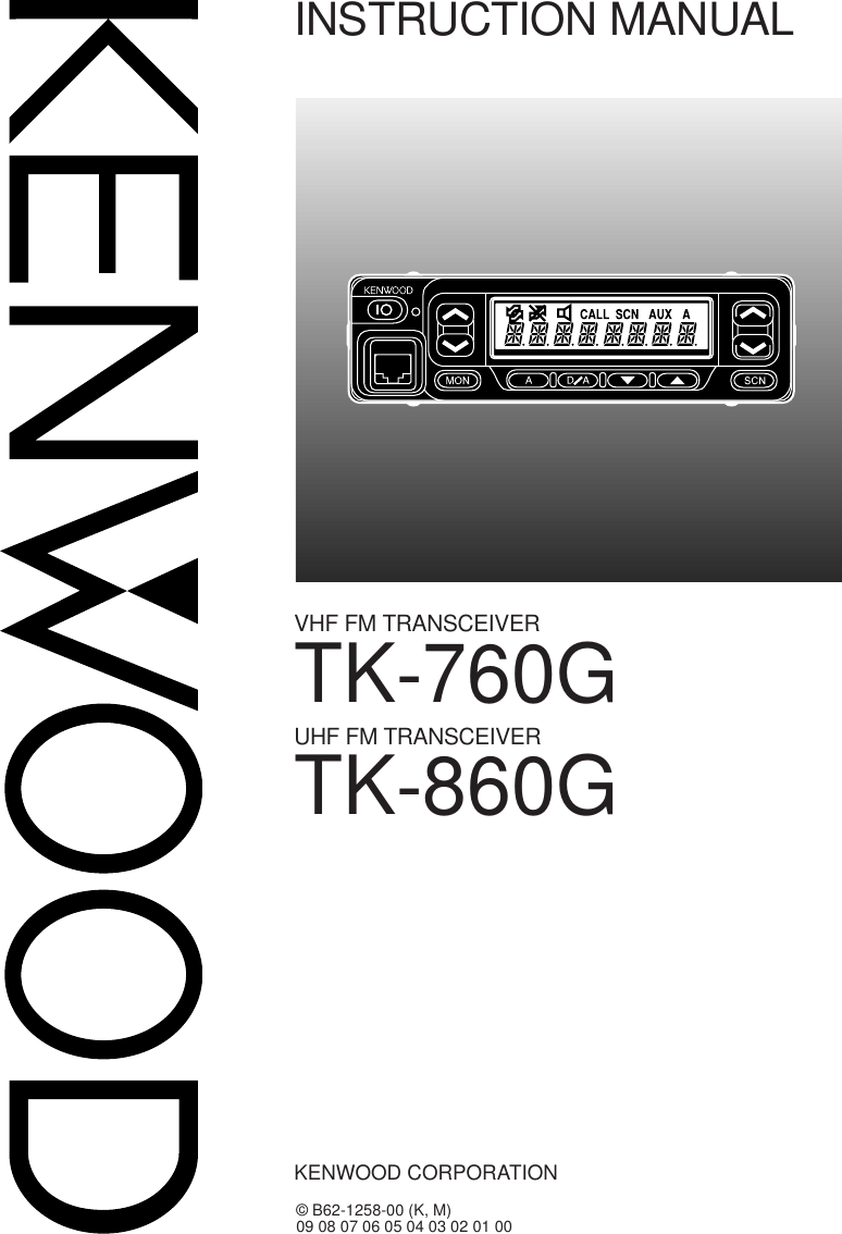
Kenwood USA 29383120 UHF-FM Mobile Transceiver User Manual TK 760G 860G front cover

Kenwood USA Corporation UHF-FM Mobile Transceiver TK 760G 860G front cover

Manual

TK-760GINSTRUCTION MANUALVHF FM TRANSCEIVER© B62-1258-00 (K, M)09 08 07 06 05 04 03 02 01 00KENWOOD CORPORATIONTK-860GUHF FM TRANSCEIVER
THANK YOU!We are grateful you chose KENWOOD for your personal mobile applications.  Webelieve this easy-to-use transceiver will provide dependable communications to keeppersonnel operating at peak efficiency.KENWOOD transceivers incorporate the latest in advanced technology.  As a result,we feel strongly that you will be pleased with the quality and features of this product.MODELS COVERED BY THIS MANUALThe models listed below are covered by this manual:•TK-760G: VHF FM Transceiver•TK-860G: UHF FM TransceiverOne or more of the following statements may be applicable:FCC WARNINGThis equipment generates or uses radio frequency energy.  Changes or modifications to thisequipment may cause harmful interference unless the modifications are expressly approved in theinstruction manual.  The user could lose the authority to operate this equipment if an unauthorizedchange or modification is made.INFORMATION TO THE DIGITAL DEVICE USER REQUIRED BY THE FCCThis equipment has been tested and found to comply with the limits for a Class B digital device,pursuant to Part 15 of the FCC Rules.  These limits are designed to provide reasonable protectionagainst harmful interference in a residential installation.This equipment generates, uses and can generate radio frequency energy and, if not installed andused in accordance with the instructions, may cause harmful interference to radio communications.However, there is no guarantee that the interference will not occur in a particular installation.  If thisequipment does cause harmful interference to radio or television reception, which can be determinedby turning the equipment off and on, the user is encouraged to try to correct the interference by one ormore of the following measures:•Reorient or relocate the receiving antenna.•Increase the separation between the equipment and receiver.•Connect the equipment to an outlet on a circuit different from that to which the receiver isconnected.•Consult the dealer for technical assistance.
i◆GOVERNMENT LAW PROHIBITS THE OPERATION OF UNLICENSED RADIOTRANSMITTERS WITHIN THE TERRITORIES UNDER GOVERNMENT CONTROL.◆ILLEGAL OPERATION IS PUNISHABLE BY FINE OR IMPRISONMENT OR BOTH.◆REFER SERVICE TO QUALIFIED TECHNICIANS ONLY.SAFETY:  It is important that the operator is aware of, and understands, hazardscommon to the operation of any transceiver.WARNING!◆EXPLOSIVE ATMOSPHERES (GASES, DUST, FUMES, etc.)Turn OFF your transceiver while taking on fuel or while parked in gasoline service stations.Do not carry spare fuel containers in the trunk of your vehicle if your transceiver is mountedin the trunk area.◆INJURY FROM RADIO FREQUENCY TRANSMISSIONSDo not operate your transceiver when somebody is either touching the antenna or standingwithin two to three feet of it, to avoid the possibility of radio frequency burns or relatedphysical injury.◆DYNAMITE BLASTING CAPSOperating the transceiver within 500 feet of dynamite blasting caps may cause them toexplode.  Turn OFF your transceiver when in an area where blasting is in progress, or where“TURN OFF TWO-WAY RADIO” signs have been posted.  If you are transporting blastingcaps in your vehicle, make sure they are carried in a closed metal box with a padded interior.Do not transmit while the caps are being placed into or removed from the container.NOTICES TO THE USERPRECAUTIONSPlease observe the following precautions to prevent fire, personal injury, andtransceiver damage.•Do not attempt to configure the transceiver while driving; it is too dangerous.•Do not modify the transceiver for any reason.•Do not expose the transceiver to long periods of direct sunlight, nor place itnear heating appliances.•Do not place the transceiver in excessively dusty, humid, or wet areas, not onunstable surfaces.•If an abnormal odor or smoke is detected coming from the transceiver, turnOFF the power immediately.  Contact your KENWOOD dealer.
iiCONTENTSUNPACKING AND CHECKING EQUIPMENTSUPPLIED ACCESSORIES ............................................................................ 1PREPARATIONTOOLS REQUIRED ......................................................................................... 2POWER CABLE CONNECTION ..................................................................... 2INSTALLING THE TRANSCEIVER ................................................................. 3ORIENTATIONFRONT PANEL AND MICROPHONE.............................................................. 4DISPLAY........................................................................................................... 5REAR PANEL................................................................................................... 5PROGRAMMABLE AUXILIARY FUNCTIONS ..................................................... 6PROGRAMMABLE FUNCTIONS .................................................................... 6BASIC OPERATIONSRECEIVING ...................................................................................................... 8Switching Powr ON/OF ............................................................................ 8Adjusting the Volume ............................................................................... 8Selecting a Channel ................................................................................. 8CALLING .......................................................................................................... 9Monitoring the channel ............................................................................ 9Busy Channel Lockout ............................................................................ 9Time-Out Timer ......................................................................................... 9ADVANCED OPERATIONSSCANNING CHANNELS ................................................................................. 9Priority Scan ............................................................................................. 9Channel lockoul ........................................................................................ 9TALK-AROUNDl ............................................................................................ 112-TONE SIGNALLING ................................................................................... 11Select and encodeing 2-tone signalling .............................................. 11HORN ALERT ................................................................................................ 12OPERATOR SELECTABLE TONE................................................................ 12PUBLIC ADDRESSS ..................................................................................... 12AUX ................................................................................................................ 12DTMF (DUAL TONE MULTI FREQUENCY) CALLSMAKING A DTMF CALL ................................................................................ 13Auto Dialing............................................................................................. 13Manual Dialing ........................................................................................ 13Store and Send Dialing .......................................................................... 13DTMF SIGNALLING ...................................................................................... 14DBD (DEAD BEAT DISABLE) ....................................................................... 14
1UNPACKING AND CHECKING EQUIPMENTNote:  The following unpacking instructions are for use by your KENWOOD dealer, an authorizedKENWOOD service facility, or the factory.Carefully unpack the transceiver.  We recommend that you identify the itemslisted in the following table before discarding the packing material.  If any itemsare missing or have been damaged during shipment, file a claim with the carrierimmediately.SUPPLIED ACCESSORIESMicrophone andmicrophone cable DC power cableMicrophone hangerwith self-tapping screwsMounting bracket Screw setSpeaker jack capmetI rebmuNtraP ytitnauQelbacenohporcimdnaenohporciMXX-7950-19T1swercsgnippat-fleshtiwregnahenohporciMXX-4851-91Jtes1elbacrewopCDXX-9333-03E1tekcarbgnitnuoMXX-7260-92J1packcajrekaepSXX-5320-90B1:teswercSXX-5930-99N1)seceip4(wercsgnippat-fleS•)seceip4(rehsawhtiwwercsdedaeh-xeH•)seceip4(rehsawgnirpS•)seceip4(rehsawtalF•)A01(esuFXX-1600-15F2)ylnoadanaC/.A.S.U(dracytnarraW––1launamnoitcurtsnIXX-7521-26B1
2WARNING!  VARIOUS ELECTRONIC EQUIPMENT IN YOUR VEHICLE MAY MALFUNCTION IF THEYARE NOT PROPERLY PROTECTED FROM THE RADIO FREQUENCY ENERGY WHICH ISPRESENT WHILE TRANSMITTING.  ELECTRONIC FUEL INJECTION, ANTI-SKID BRAKING, ANDCRUISE CONTROL SYSTEMS ARE TYPICAL EXAMPLES OF EQUIPMENT THAT MAYMALFUNCTION.  IF YOUR VEHICLE CONTAINS SUCH EQUIPMENT, CONSULT THE DEALER FORTHE MAKE OF VEHICLE AND ENLIST HIS AID IN DETERMINING IF THEY WILL PERFORMNORMALLY WHILE TRANSMITTING.Note:  The following preparation instructions are for use by your KENWOOD dealer, an authorizedKENWOOD service facility, or the factory.TOOLS REQUIREDNote:  Before installing the transceiver, always check how far the mounting screws will extend below themounting surface.  When drilling mounting holes, be careful not to damage vehicle wiring or parts.The following tools are required for installing the transceiver:•6 mm (1/4 inch) or larger electric drill•Drill bits (sizes listed below) and circle cuttersPOWER CABLE CONNECTIONCAUTION:  THE TRANSCEIVER OPERATES IN 12 V NEGATIVE GROUND SYSTEMS ONLY!CHECK THE BATTERY POLARITY AND VOLTAGE OF THE VEHICLE BEFORE INSTALLING THETRANSCEIVER.1Check for an existing hole, conveniently located in the firewall, where thepower cable can be passed through.•If no hole exists, use a circle cutter to drill the firewall, then install a rubbergrommet.2Run the two power cable leads through the firewall and into the enginecompartment, from the passenger compartment.3Connect the red lead to the positive (+) battery terminal and the black lead tothe negative (–) battery terminal.•Locate the fuse as close to the battery as possible.4Recoil and secure the surplus cable with the provided retaining band.•Be sure to leave enough slack in the cables so the transceiver can be removed forservicing while keeping the power applied.PREPARATIONeziStiBllirD esopruP)hcni23/5(mm2.4swercsgnippat-flesmm61x5)hcni8/1(mm2.3swercsgnippat-flesmm61x4
3INSTALLING THE TRANSCEIVERWARNING!  FOR PASSENGER SAFETY, INSTALL THE TRANSCEIVER SECURELY, USING THESUPPLIED MOUNTING BRACKET, SO THE TRANSCEIVER WILL NOT BREAK LOOSE IN THEEVENT OF A COLLISION.1Mark the position of the holes in the dash by using the mounting bracket as atemplate.  Drill the holes, then attach the mounting bracket using the supplied5 x 16 mm screws.•Be sure to mount the transceiver in a location where the controls are within easyreach of the user, and where there is sufficient space at the rear of the transceiverfor cable connections.2Connect the antenna and the supplied power cable to the transceiver.3Slide the transceiver into the mounting bracket and secure it using thesupplied hex-headed screws.4Mount the microphone hanger, using the supplied 4 x 16 mm screws, in alocation where it will be within easy reach of the user.•The microphone and microphone cable should be mounted in a place where theywill not interfere with the safe operation of the vehicle.5Connect one plug of the microphone cable to the jack on the base of themicropohone, and the other plug to the microphone jack on the front panel ofthe transceiver.  Place the microphone on the hanger.Hex-headed screwMicrophonehangerDC power cableMountingbracket5 x 16 mmself-tapping screw4 x 16 mmself-tapping screwSpring washerFlat washerAntennaconnectorPower inputconnector
4ORIENTATIONFRONT PANEL AND MICROPHONEqqqqqIO (Power) switchPress to switch the transceiver ON (or OFF).wwwwwStatus LEDRed LED indicats that the transceiver is transmitting.  Green LED indicatesthat the transceiver is receiving the signal.eeeee /   keysPress these keys to activate their programmable auxiliary functions{page 7}.  Default setting is VOLUME Up/Down keys.rrrrrDisplaySee page 5 for more information.ttttt /   keysPress these keys to activate their programmable auxiliary functions{page 7}.  Default setting is Channel Up/Down keys.yyyyyMicrophone connectorInsert the microphone plug into this connector.uuuuuMON, A, D/A,  ,  ,  and SCN keysPress these keys to activate their programmable auxiliary functions{page 7}.iiiiiPTT switchTo transmit, press and hold this switch, then speak into the microphone.Release to receive.qyuwrtei
5DISPLAYREAR PANELExternalspeaker jackPower inputconnectorAntenna connectorrotacidnI noitpircseD.reviecsnartsihtnodesutonsinocisihTdetcelesyltnerrucehtnotneserperaslangisnehwsraeppA .lennahc.detavitcasinoitcnufrotinoMehtnehwsraeppAenot-2demmargorperphtiwdellacevahuoynehwsraeppA .ytraprehtonamorfllacevitcelesFMTDroedocgnillangis.gninnacssireviecsnartehtelihwsraeppA.resuehtybdetavitcasitropXUAelihwsraeppA.”tsilnacS“nisilennahcdeyalpsidehtnehwsraeppApuorg,srebmunlennahcehtsyalpsidtI.yalpsidniamA ehtmargorpnacrelaedruoY.sutatssuoiravdnasrebmun .srebmunfoecalpni,sretcarahc01otpuhtiwsemanlennahc
6PROGRAMMABLE AUXILIARY FUNCTIONS KEYSThe following keys can be programmed with the auxiliary functions listed in thetable on next page.Note:◆For your reference, please fill out the form above with the programmed function by your dealer.◆A list of the programmable functions is available on the next page.rebmuNyeK gnittesoidarruoY gnittestluafedyrotcaFqpUemuloVwnwoDemuloVepUlennahCrnwoDlennahCtArotinoMy---u---i---o---0! ---qt y u i o !0wer
7PROGRAMMABLE FUNCTIONS1This function can be used only with a foot switch.emantrohS noitpircseDXUAtropXUAetavitcAnwoDlennahCrebmunlennahcehtesaerceDpUlennahCrebmunlennahcehtesaercnIretcarahCyalpsiDpuorG,yalpsidrebmunlennahcneewtebelggoT emanlennahcciremun-ahpladnayalpsid yalpsidycnegremE1edomycnegremeehtetavitcAnwoDpuorGrebmunpuorgesaerceDpUpuorGrebmunpuorgesaercnIlennahCemoHlennahcemohteserpaotnruteRtrelAnroHnoitcnuftrelAnroHetavitcAkcoLyeKyekrewopatpecxesyekllakcoLArotinoM ))yratnemoM(etumnUrotinoM(yeksihthsupuoyelihwlennahcehtrotinoM))elggoT(etumnUrotinoM(BrotinoMffodnanonoitcnufrotinomelggoTCrotinoM ))yratnemoM(hcleuqSreirraC(ehtnepodnagnillangisenot-2/TQD/TQelbasiD .ylnoreirracgnimocniehthtiwhcleuqs))elggoT(hcleuqSreirraC(DrotinoMdnanonoitcnufehtselggoT.evobasaemaS ffonoitcnufoNnoitcnufoN)ylnoepyt-K(enoTelbateleSrotarepO61morftesenotatcelesresuateL sriapenotTQD/TQdemmargorperpsserddAcilbuPnoitcnufsserddAcilbuPetavitcAlaideRrebmuntsalehtlaideRnacSruoyybdemmargorpsaslennahcehtnacS relaedddA/leDnacSgninnacsehtot/morflennahcehtddaroeteleD tsillennahcdnuorAklaTycneuqerfeviecerehtnotimsnartotecroFnwoDemuloVemulovehtesaeceDpUemuloVemulovehtesaercnItceleSedocnEenoT-2enot-2demmargorperp01fo1tcelesresuateL .sriap
8BASIC OPERATIONSRECEIVINGYour dealer may have programmed QT or DQT signalling for the channel thatyou select.  If the channel has been programmed in this way, you will heartransmissions from your group only.  Otherwise, you will hear all thetransmissions made any stations using the same channel.■ Switching Power ON/OFFPress the IO switch to switch the transceiver ON (or OFF).■ Adjusting the VolumePress the key programmed as Volume Up or Volume Down to adjust thevolume.  Volume Up increases the volume and Volume Down decreases it.■ Selecting a ChannelSelect the desired channel system using the keys programmed with the ChannelUp and Down keys.Note: TK-760G/ TK-860G features 128-channel capacity.  In order to manage 128 channels easily, oneor more programmed channels can be bundled together as a group.Your dealer may have also programmed Group Up and Down keys.  In this case, please select thedesired group and channel number.  Please consult your dealer for the details.
9CALLING■ Monitoring the channelPress MON key (or a key programmed as Monitor) to monitor the channel fora few seconds to confirm that channel is not being used.After the confirmation, hold the microphone about 3 to 4 cm (1 1/2 inches)from your mouth, press microphone PTT , and speak in your normal speakingvoice.Release PTT and listen to a response.■ Busy Channel LockoutActivated or deactivated by your dealer, this function prevents you frominterfering with other stations that my be using a channel.  Pressingmicrophone PTT while the selected channel is in use causes your transceiverto generate an audible warning tone.  Your transceiver is inhibited in thissituation so it will not transmit.  Release microphone PTT to canel the alarmand restore the receive mode.■ Time-Out TimerThe purpose of the time-out timer is to automatically interrupt continuoustransmissions after a specified time elapses.  Holding down microphone PTTfor longer than the programmed time causes the transceiver to stoptransmitting and generate a warning tone.  Releasing microphone PTTcancels the warning tone.
10SCANNING CHANNELSIf the Scan function is enabled, groups or channels can be scanned by pressingthe key programmed as Scan.  A Scan key can be programmed as either SingleScan or Multi Scan by your dealer.Single Scan monitors only the channels of a single group.  Multi Scan monitorsall channels of every group.  When the Scan key is pressed, the SCN indicatorand "SCAN" appear on the display and the scanning starts.When a call is received on one of scanning channels, scanning stops and thechannel information appears on the display.  Press PTT switch and speak intothe microphone to respond to the call.  The transceiver will continue scanningafter an adjustable time delay, if PTT switch is released, and no further signal isreceived.■Priority ScanEither Fixed priority scan or Selectable priority scan may be programmed byyour dealer.•Fixed Priority Scan: The pre-programmed channel is monitored in acertain interval while scanning. When the signal is being received on thispriority channel while scanning, you will be transfered to this prioritychannel.•Selectable Priority Scan: After you select the priority channe usingChannel Up/Down or Group Up/Down keys, press a Scan key,programmed by your dealer.  The scanning starts and the selected prioritychannel is monitored in a certain interval while scanning.  When the signalis being received on the selected priority channel while scanning, you willbe transfered to this priority channel.■Channel lockoutIf the channel lockout is enabled by your dealer, you can select channels toadd or delete from the scaning channel list.  When the displayed channel isnot locked out from the scanning, the add indicator A (Add) will appear on thedisplay.1.  Using Channel Up and Down key to select the channel that you wish toadd or delete from the scanning list.2.  Press a Delete/Add key, programmed by your dealer to add or delete thechannel to/from the scanning channel list.  If the channel is in the scanninglist, A (Add) indicator will be lit on the upper right side of the display.  A(Add) indicator is disappeared from the display, the channel is no longer inthe scanning channel list.ADVANCED OPERATIONS
11TALK-AROUNDOccasionally, a power failure or other cause at the repeater may result in aninterruption of service.  Your dealer may have provided the Talk-around functionfor use in such cases.  This function allows communication directly with othertranceivers without using a repeater.  However, even Talk-around may not allowyou to contact a station if the distance is too far or there are geographicobstacles in the way.To enable Talk-around function, press a key, programmed as Talk-around."TA" or "T." (depending on the configuration) will be displayed at the left side ofLCD display.Note: When you are in Talk-around mode, all the signalling data, such as QT,DQT, 2-tones are still enabled.2-TONE SIGNALLING2-tone signalling is either enabled or disabled by your dealer.  2-tone opens thesquelch only when the transceiver receives the preset two sequential tones thathave different frequencies.When the correct tones are received that were programmed by your dealer, thesquelch opens, and the caller's voice is monitored.■Select and encoding 2-tone signallingIf "2-tone encode select" is programmed by your dealer, you can select 1of 10preset 2-tone codes.  Then you can sent the desired 2-tone toanother party.1  Press a key, programmed as 2-tone encode select .2  Select the desired a tone set, using Channel Up and Down key.3  Press 2-tone encode select key again to set.4  Press PTT to send the tone to another party.
12HORN ALERTWhen a call is received that has correct DTMF codes or 2-tone signalling, HornAlert causes the vehicle horn or some other external alert to sound.  Thisfunction notifies you of a received call when you are out of the vehicle.1  To activate the Horn Alert, press the function key programmed as Horn Alert.2  To disable the Horn Alert, press a Horn Alert  function key again to return tothe normal operation.OPERATOR SELECTABLE TONEIf this function is enabled by your dealer, you can change the default QT andDQT tone frequencies.  You can select 1 of 16 decode/ encode pairs, that ispreset by your dealer.1  Use Channel Up and Down key to select the desired channel2  Press a key, programmed as Operator Selectable Tone.3  Use Channel Up and Down key to select a desired tone pair.4  Press a key in step 2 again to return to the normal display.PUBLIC ADDRESSTo use Public Address, the optional PA unit (KAP-1) and external speaker mustbe installed by your dealer.  This function amplifies audio input from themicrophone and outputs amplified audio from the external speaker.1  Press the function button programmed by your dealer with this function2  Press PTT and speak into the microphone.Note: To adjust the audio output from the external speaker, please use Volume Up and Down keys to getthe appropriete sound.3  To return to the normal operation, press the PA function key again.AUXA control port has been provided for an external board, such as a VoiceScrambler.  Pressing the function button programmed by your dealer, activatesor deactivates the AUX port.
13DTMF (DUAL TONE MULTI FREQUENCY) CALLSMAKING A DTMF CALLNote:  To make a DTMF call, you must have an optional microphone with a DTMF keypad.  Ask yourdealer for more information.There are three ways of making a DTMF call:•Auto dialing•Manual dialing•Store and send dialing■ Auto dialing1Press * key on DTMF microphone.2Press one of numeric key, 1~9.•Preprogrammed numbers appears on the display.3 Push PTT to send the numbersNote:◆Maximum length of the proprogrammed number is 16 digits.■ Manual dialing1Press and hold the PTT switch.2Enter the desired digits using the microphone keypad.•The corresponding DTMF tones sound each time you press a key.•If you release the PTT switch, transmit mode will end even if the complete numberhas not been sent.•If your dealer has activated the Keypad Auto PTT function, you need not hold downthe PTT switch while pressing the keys on the keypad.  The DTMF code will besent automatically when you press a key.■ Store and send dialing1Enter the desired digits using the microphone keypad.•The digits appear on the display as you enter them.2After entering the complete number, press the PTT switch.•The DTMF code is transmitted after pressing the PTT switch.Note:◆Store and send must first be activated by your dealer in order for it to function.◆You can only store up to 16 digits before sending.  Entering more than 16 digits will cause an errortone to sound.◆In store and sending mode, if you switch the power OFF before sending the number, the number willbe cleared from memory.
14DTMF SIGNALLINGYour dealer can program a group or channel with DTMF signalling.  When youreceive a call with a code that matches yours, a tone will sound.  Squelch opensand you will hear the call.Squelch will close when you receive a call with a code that matches yoursignalling reset code.When making a call on a group or channel programmed with a DTMF signallingcode, the indicator will light and the squelch will open.If your dealer programmed Transpond for DTMF signalling, your transceiver willautomatically send an acknowledgment signal to the station that called you withthe correct DTMF code.DBD (DEAD BEAT DISABLE)Depending on how your dealer programs your transceiver, when you receive acall containing a DBD code, either transmit mode or receive and transmit modeswill be disabled.  When a DBD code is received, a tone will sound.DBD is cancelled when you receive a call with a DBD cancel code.

Navigation menu