Kenwood USA 29432110 VHF-FM Mobile Transceiver User Manual TK 785 885 E 00 Cover
Kenwood USA Corporation VHF-FM Mobile Transceiver TK 785 885 E 00 Cover
Manual

© B62-1262-00 (K,M,E)
09 08 07 06 05 04 03 02 01 00
KENWOOD CORPORATION
INSTRUCTION MANUAL
VHF FM TRANSCEIVER/ UHF FM TRANSCEIVER
TK-785/ TK-885

i
THANK YOU
We are grateful you chose KENWOOD for your personal mobile applications.
We believe this easy-to-use transceiver will provide dependable communications
to keep personnel operating at peak efficiency.
KENWOOD transceivers incorporate the latest in advanced technology. As a
result, we feel strongly that you will be pleased with the quality and features of
this product.
MODELS COVERED BY THIS MANUAL
•TK-785: VHF FM Transceiver
•TK-885: UHF FM Transceiver
PRECAUTIONS
Please observe the following precautions to prevent fire, personal injury, and
transceiver damage.
• Do not attempt to configure the transceiver while driving; it is too dangerous.
• Do not modify the transceiver for any reason.
• Do not expose the transceiver to long periods of direct sunlight, nor place it near
heating appliances.
• Do not place the transceiver in excessively dusty, humid, or wet areas, nor on
unstable surfaces.
• If an abnormal odour or smoke is detected coming from the transceiver, turn OFF the
power immediately. Contact your KENWOOD dealer.
NOTICES TO THE USER
◆
GOVERNMENT LAW PROHIBITS THE OPERATION OF UNLICENSED RADIO
TRANSMITTERS WITHIN THE TERRITORIES UNDER GOVERNMENT CONTROL.
◆
ILLEGAL OPERATION IS PUNISHABLE BY FINE AND/OR IMPRISONMENT.
◆
REFER SERVICE TO QUALIFIED TECHNICIANS ONLY.
SAFETY: It is important that the operator is aware of, and understands, hazards
common to the operation of any transceiver.
WARNING!
◆
EXPLOSIVE ATMOSPHERES (GASES, DUST, FUMES, etc.)
Turn OFF your transceiver while taking on fuel or while parked in a gasoline service station. Do
not carry spare fuel containers in the trunk of your vehicle if your transceiver is mounted in the
trunk area.
◆
INJURY FROM RADIO FREQUENCY TRANSMISSIONS
Do not operate your transceiver when somebody is either touching the antenna or standing within
two to three feet of it, to avoid the possibility of radio frequency burns or related physical injury.
◆
DYNAMITE BLASTING CAPS
Operating the transceiver within 500 feet of dynamite blasting caps may cause them to explode.
Turn OFF your transceiver when in an area where blasting is in progress, or where “TURN OFF
TWO-WAY RADIO” signs have been posted. If you are transporting blasting caps in your vehicle,
make sure they are carried in a closed metal box with a padded interior. Do not transmit while
the caps are being placed into or removed from the container.

ii
CONTENTS
UNPACKING AND CHECKING EQUIPMENT ............................................... 1
Supplied Accessories.............................................................................. 1
PREPARATION ............................................................................................... 2
Tools Required ......................................................................................... 2
Power Cable Connection ........................................................................ 2
Installing the Transceiver........................................................................ 3
THE BASICS ................................................................................................... 4
Front Panel ............................................................................................... 4
Rear Panel................................................................................................. 5
Switching Power ON/ OFF ...................................................................... 5
Adjusting the Volume .............................................................................. 5
TRUNKING MODE .......................................................................................... 6
Key Functions .......................................................................................... 6
Programmable Auxiliary Functions ....................................................... 6
Display ...................................................................................................... 7
Searching for a Control Channel ........................................................... 7
Voice Calls ................................................................................................ 8
Making a Voice Call ............................................................................ 8
Receiving a Voice Call ....................................................................... 9
Status Calls............................................................................................... 9
Making a Status Call .......................................................................... 9
Receiving a Status/Short Data Message Call................................ 10
Call Displays ........................................................................................... 10
Viewing the Stack .................................................................................. 10
Call Diversions ....................................................................................... 11
Diverting Your Own Calls ................................................................ 11
Diverting Third Party Calls .............................................................. 11
CONVENTIONAL MODE .............................................................................. 12
Key Functions ........................................................................................ 12
Display .................................................................................................... 12
Entering Conventional Mode ................................................................ 13
Returning to Trunking Mode ................................................................. 13
Conventional Mode Operation ............................................................. 13
Scanning ................................................................................................. 14
APPENDIX..................................................................................................... 15
1
UNPACKING AND CHECKING EQUIPMENT
Note: The following unpacking instructions are for use by your KENWOOD dealer, an authorized
KENWOOD service facility, or the factory.
Carefully unpack the transceiver. We recommend that you identify the items
listed in the following table before discarding the packing material. If any items
are missing or have been damaged during shipment, file a claim with the carrier
immediately.
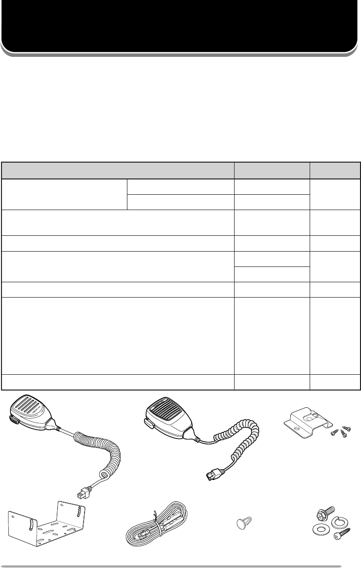
Supplied Accessories
Microphone
(TK-785 E only) Microphone
(TK-885 K, K3 only)
Power cable assemblyMounting bracket
metI rebmuNtraP ytitnauQ
dnaenohporciM elbacenohporcim
ylnoE587-KTXX-0733-06X 1
ylno3K,K588-KTXX-7950-19T
swercsgnippat-fleshtiwregnahenohporciM )enohporcimagniniatnocstikhtiwylnodeilppus( XX-4851-91J1
tekcarbgnitnuoMXX-7260-92J1
ylbmessaelbacrewoPXX-9333-03E 1
)seceip2(esuFA01•XX-1600-15F
packcajrekaepSXX-5320-90B1
:teswercS
XX-5930-99N1
)seceip4(wercsgnippat-fleS•
)seceip4(rehsawhtiwwercsdedaeh-xeH•
)seceip4(rehsawgnirpS•
)seceip4(rehsawtalF•
launamnoitcurtsnIXX-2621-26B1
Microphone
hanger
Speaker jack cap Screw set
2
VARIOUS ELECTRONIC EQUIPMENT IN YOUR VEHICLE MAY MALFUNCTION IF THEY ARE
NOT PROPERLY PROTECTED FROM THE RADIO FREQUENCY ENERGY WHICH IS PRESENT
WHILE TRANSMITTING. ELECTRONIC FUEL INJECTION, ANTI-SKID BRAKING, AND CRUISE
CONTROL SYSTEMS ARE TYPICAL EXAMPLES OF EQUIPMENT THAT MAY MALFUNCTION. IF
YOUR VEHICLE CONTAINS SUCH EQUIPMENT, CONSULT THE DEALER FOR THE MAKE OF
VEHICLE AND ENLIST HIS AID IN DETERMINING IF THEY WILL PERFORM NORMALLY WHILE
TRANSMITTING.
Note: The following preparation instructions are for use by your KENWOOD dealer, an authorized
KENWOOD service facility, or the factory.
Tools Required
Note: Before installing the transceiver, always check how far the mounting screws will extend below the
mounting surface. When drilling mounting holes, be careful not to damage vehicle wiring or parts.
The following tools are required for installing the transceiver:
• 6 mm (1/4 inch) or larger electric drill.
• 4.2 mm (5/32 inch) drill bit for the 5 x 16 mm self-tapping screws, and 3.2 mm
(1/8 inch) drill bit for the 4 x 16 mm self-tapping screws.
• Circle cutters.
Power Cable Connection
THE TRANSCEIVER OPERATES IN 12 V NEGATIVE GROUND SYSTEMS ONLY! CHECK THE
BATTERY POLARITY AND VOLTAGE OF THE VEHICLE BEFORE INSTALLING THE
TRANSCEIVER.
1Check for an existing hole, conveniently located in the firewall, where the
power cable can be passed through.
• If no hole exists, use a circle cutter to drill the firewall, then install a rubber
grommet.
2Run the two power cable leads through the firewall and into the engine
compartment, from the passenger compartment.
3Connect the red lead to the positive (+) battery terminal and the black lead to
the negative (–) battery terminal.
• Locate the fuse as close to the battery as possible.
4Coil and secure the surplus cable with a retaining band.
• Be sure to leave enough slack in the cables so the transceiver can be removed for
servicing while keeping the power applied.
PREPARATION
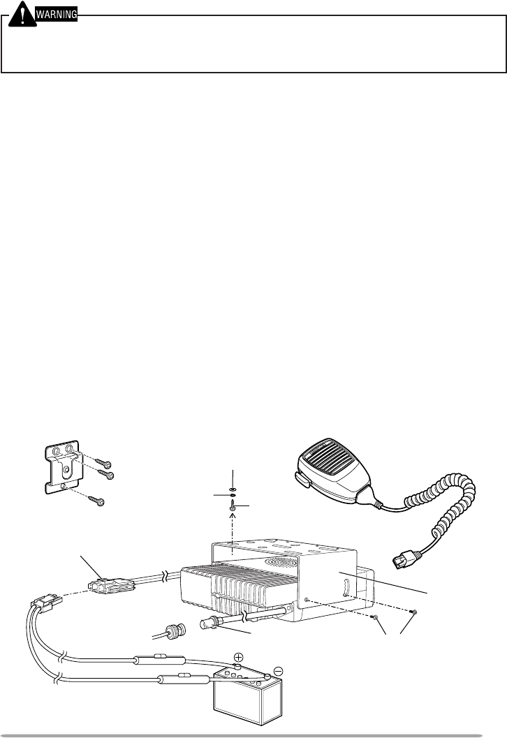
3
Hex-headed screw
DC power cable
Mounting
bracket
5 x 16 mm
self-tapping screw
Spring washer
Flat washer
Antenna
connector
Power input connector
FOR PASSENGER SAFETY, INSTALL THE TRANSCEIVER SECURELY, USING THE SUPPLIED
MOUNTING BRACKET, SO THE TRANSCEIVER WILL NOT BREAK LOOSE IN THE EVENT OF A
COLLISION.
1Mark the position of the holes in the dash by using the mounting bracket as a
template. Drill the holes, then attach the mounting bracket using the supplied
5 x 16 mm screws.
• Be sure to mount the transceiver in a location where the controls will be within easy
reach of the user and where there is sufficient space at the rear of the transceiver
for cable connections.
2Connect the antenna and the supplied power cable to the transceiver.
3Slide the transceiver into the mounting bracket and secure it using the
supplied hex-headed screws.
4Mount the microphone hanger, using the supplied 4 x 16 mm screws, in a
location where it will be within easy reach of the user.
• The microphone should be mounted in a place where it will not interfere with the
safe operation of the vehicle.
5Connect the microphone cable to the jack on the front panel of the
transceiver. Place the microphone on the hanger.
Installing the Transceiver
Vehicle
battery
Microphone and
microphone cable
Microphone hanger
4
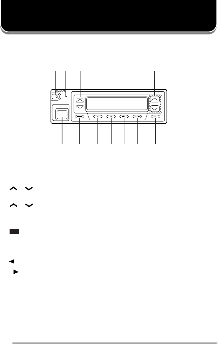
THE BASICS
qq
qq
qIO (Power) switch
Press to switch the transceiver ON (or OFF).
ww
ww
wTransmit/ Receive indicator
ee
ee
e/(Volume) keys
Press these keys to increase and decrease the volume.
rr
rr
r/(Control) keys
tt
tt
tMicrophone jack
Insert the microphone plug into this connector.
yy
yy
y key
uu
uu
uA key
ii
ii
iB key
oo
oo
oC key
!0!0
!0!0
!0 D key
!1!1
!1!1
!1 CALL key
q w
ty u i o !1!0
er
Note: Features listed in this section are available for both Trunking and Conventional modes. Mode
specific features can be found in their corresponding sections in this manual.
Front Panel
5
Switching Power ON/ OFF
Press the IO switch to switch the transceiver ON. The power on text or unit
number appears for 2 seconds.
Press the IO switch again to switch the transceiver OFF.
Adjusting the Volume
Press the /(volume) keys to adjust the volume. increases the
volume and decreases it.
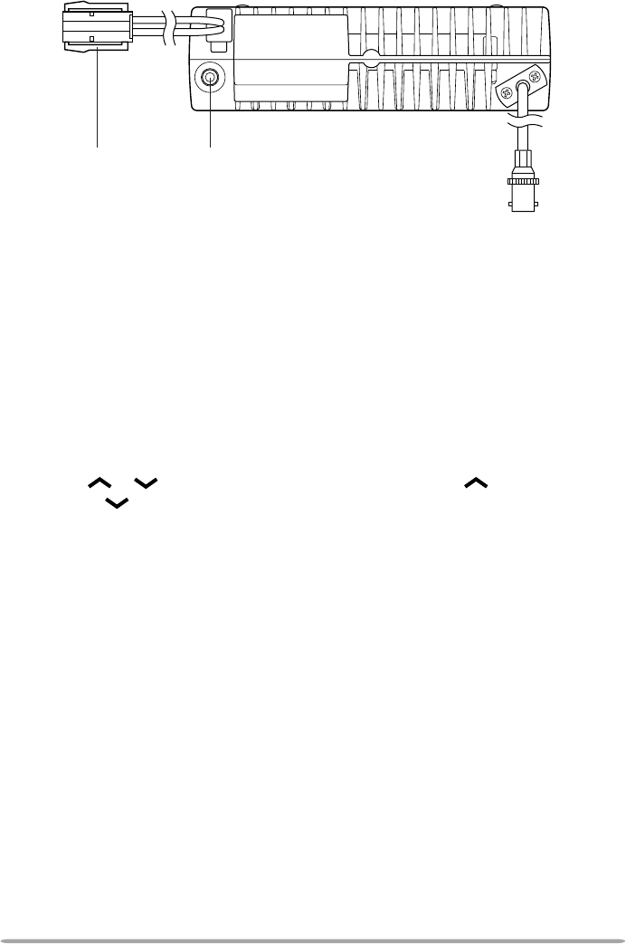
Rear Panel
External
speaker jack
Power input
connector
Antenna connector

6
TRUNKING MODE
Key Functions
Note: The numbers correspond to the diagram on page 4.
ww
ww
wTransmit indicator
Lights red while transmitting.
rr
rr
r/(Control) keys
Press these keys to select your desired call address (voice calls) or status
(status calls).
yy
yy
y key
Press to end the current call.
uu
uu
uA key (default setting: Status/ Stack)
Press to activate its auxiliary function {below}.
ii
ii
iB key (default setting: Redial)
Press to activate its auxiliary function {below}.
oo
oo
oC key (default setting: None)
Press to activate its auxiliary function {below}. Also press to scroll left while
viewing stack entries.
!0!0
!0!0
!0 D key (default setting: None)
Press to activate its auxiliary function {below}. Also press to scroll right while
viewing stack entries.
!1!1
!1!1
!1 CALL key
Press to call the displayed call address.
Programmable Auxiliary Functions
The A, B, C, and D keys, as well as the external foot switch, can be
programmed with the auxiliary functions listed below. Contact your dealer for
details on these functions.
Note: Some of these functions cannot be programmed onto certain keys. Ask your dealer for details.
• AUX A • Key Lock
• AUX B • Network Select
• Conventional • None
• Dialing • Public Address
• Emergency • Redial
• Home • Scrambler
• Horn Alert • Status/ Stack
7
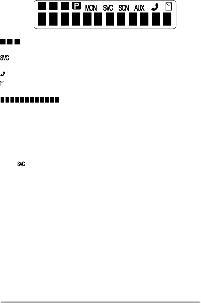
Display
displays the strength of received signals, the output power (high or low),
status numbers, and received call types.
appears when a control channel is found. It flashes while the transceiver is
searching for a control channel.
flashes when you activate call diversion.
appears while there is data in the stack. It flashes when there is new data in
the stack.
displays call addresses, the call duration timer, data
messages, and the current operating status of the transceiver.
Searching for a Control Channel
After switching the power ON, press any key while the power on text or unit
number is displayed to begin searching for a control channel. Or, wait for
2 seconds to allow the transceiver to start searching for a control channel
automatically.
• The indicator flashes and an arrow scrolls across the display while the transceiver
is searching for a control channel.

8
Voice Calls
■Making a Voice Call
1Select a call address using one of the following four methods:
i)
Select a call address from memory:
Select your desired call address
using the /(control) keys if a call address has been stored in
the transceiver memory.
ii)
Use a pre-programmed key:
Press key A, B, C, or D to select a
call address if they have been pre-programmed with call addresses.
iii)
Select a call address from the stack:
Use a received voice call from the
stack as a call address (refer to “Viewing the Stack”, on page 10).
iv)
Enter a call address using the microphone keypad:
Enter your desired
call address using the microphone keypad (keys 0 ~ 9,, and #).
Refer to the appendix {page 15} for the available dial strings and
control codes.
2Initiate the call, depending on how you selected the call address.
i, ii, and iii (of step 1):
When selecting a call address from memory or the stack, press the CALL
key (or the microphone PTT switch if “PTT to Initiate Call” has been
programmed) to initiate the call.
iv (of step 1):
When using MPT1343 dialing, press the microphone # key to initiate the
call.
• “Calling” appears on the display.
3When the call is connected, a timer appears on the display.
• The timer can be set up to either count up (increasing number) or count down
(decreasing number).
4Press the microphone PTT switch to transmit; release it to receive.
• The LED lights red while transmitting.
• The 3-digit sub-display shows your transmit power. A single triangle (▲)
represents low power while dual triangles (▲▲) represents high power.
5Press the key to end the call. If the call time expires before you press
the key, the call will be automatically terminated.
• “END” momentarily appears on the display before returning to the call address
of the call you just made.

9
■Receiving a Voice Call
1When a call is received, the caller’s unit number appears on the main
display and “CAL” appears on the 3-digit sub-display.
• If you have the caller’s address set up in your transceiver, the call address is
displayed instead of the unit number.
• Group conference calls are represented by “GRP” rather than “CAL”. Group
broadcast calls are represented by “BCC”.
• Special calls are denoted as follows:
I-Fleet:
A call from a different fleet (Inter Fleet).
I-Prefix:
A call from a different prefix (Inter Prefix).
PABX:
A call from a PABX telephone system.
PSTN:
A call from a PSTN telephone system.
2Press the microphone PTT switch to respond to the call.
• The remaining call time appears on the display.
3When the call ends, the display returns to the call address which was
previously displayed. However, if you end the call by pressing the key,
“END” momentarily appears on the display before returning to the call
address.
Status Calls
■Making a Status Call
1Select a call address using one of the following two methods:
i)
Select a call address from memory:
Select your desired call address
using the /(control) keys if a call address has been stored in
the transceiver memory.
ii)
Enter a call address using the microphone keypad:
Enter your desired
call address using the microphone keypad (keys 0 ~ 9,, and #).
Refer to the appendix {page 15} for the available dial strings and
control codes.
2Press the Status/ Stack key (default is the A key), then press the /
(control) keys to select your desired status.
• The status number appears on the 3-digit sub-display.
3Press the CALL key (or microphone PTT switch if “PTT to Initiate Call” is
programmed in the transceiver) to send the status.
• “Calling” appears on the display.
4When the status has been received by the called party, “Complete”
momentarily appears on the display before returning to the call address of
the call you just made.

10
■Receiving a Status/Short Data Message Call
1When a call is received, the indicator appears on the display and
flashes.
• The indicator remains on the display when there is data in the stack.
2To view the status or message, refer to “Viewing the Stack”, below.
Call Displays
The following messages may appear on the display under certain circumstances:
Holding:
The transceiver is confirming the call made by the base station.
Engaged:
The called party is in another call.
Queued:
All communication channels are currently in use; your status will be
sent when a channel becomes free.
Fail:
The control station received an invallid call.
NU:
You entered an invallid call address.
No Reply:
The called party has been called, but they did not respond to the call.
Call Back:
The called party has set their transceiver to queue all incoming calls.
Sys Busy:
The system is currently busy.
Viewing the Stack
1Press the Status/ Stack key (default is the A key) twice to enter the stack.
• If there is no data in the stack, “------------” appears on the main display and “-00”
appears on the 3-digit sub-display.
2Press the /(control) keys to view the stack entries.
• “NEW” represents a new entry, “S” represents a status stack entry, “V” represents a
voice stack entry, and “D” represents a data stack entry.
3Press the C and D keys to scroll through the selected entry, to view the
entire entry.
4To erase an entry, select the desired entry and press the key.

11
Call Diversions
■Diverting Your Own Calls
1Enter control code “ 41” with the microphone keypad.
2Press the microphone key, then enter the unit number where you want
to divert the calls.
3Press the microphone # key or the CALL key.
• “Calling” appears on the display. While your request is being processed,
“Holding” appears on the display. When the call divert is set, “Complete”
momentarily appears on the display before returning to the previously selected
call address. The indicator appears on the display and flashes.
4To end the call diversion, enter control code “#41” with the microphone
keypad, then press the microphone # key or the CALL key.
• “Calling” appears on the display. While your request is being processed,
“Holding” appears on the display. When the call divert is cleared, “Complete”
momentarily appears on the display before returning to the previously selected
call address.
■Diverting Third Party Calls
1Enter control code “ 44” with the microphone keypad.
2Press the microphone key, then enter the unit number of the transceiver
which you want to divert the calls.
3Press the microphone # key or the CALL key.
• “Calling” appears on the display. While your request is being processed,
“Holding” appears on the display. When the call divert is set, “Complete”
momentarily appears on the display before returning to the previously selected
call address.
4To end the call diversion, enter control code “#44” with the microphone
keypad, press the microphone key, enter the unit number of the
transceiver whose calls are being diverted, then press the microphone #
key or the CALL key.
• “Calling” appears on the display. While your request is being processed,
“Holding” appears on the display. When the call divert is cleared, “Complete”
momentarily appears on the display before returning to the previously selected
call address.
12
CONVENTIONAL MODE
Key Functions
Note: The numbers correspond to the diagram on page 4.
ww
ww
wReceive indicator
Lights green while receiving a signal.
rr
rr
r/(Control) keys
Press these keys to select your desired channel.
yy
yy
y key
Press to return to Trunking mode.
uu
uu
uA key
Press to turn Scan ON (or OFF).
ii
ii
iB key
Press to add/remove channels to/from Scan.
!1!1
!1!1
!1 CALL key
Press to turn the squelch OFF in order to monitor your selected channel.
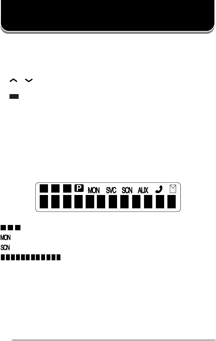
Display
displays the strength of received signals.
appears while you are monitoring a channel by pressing the CALL key.
appears while you are scanning.
displays channel numbers and the current operating
status of the transceiver.

13
Entering Conventional Mode
Depending on how your transceiver is programmed, you can enter Conventional
mode in one of two ways:
Manual:
Press the key programmed as Conventional to change the operating
mode.
Auto:
The transceiver automatically changes to Conventional mode when you
are outside the network area.
Returning to Trunking Mode
Depending on how your transceiver is programmed, you can return to Trunking
mode in one of three ways:
Manual:
Press the key to change the operating mode.
Auto:
While in Conventional mode, the transceiver periodically searches for the
network. When it finds the network, the transceiver automatically changes to
Trunking mode. An alert tone sounds to notify you when the operating mode
changes.
Alert:
While in Conventional mode, the transceiver periodically searches for the
network. When it finds the network, an alert tone sounds. Press the key to
change the operating mode.
Conventional Mode Operation
1Press the /(control) keys to select your desired channel.
2Press the CALL key to turn squelch OFF in order to monitor any activity on
the channel.
• The indicator appears on the display.
• The LED lights green and you will hear background noise.
3Press the microphone PTT switch to transmit; release it to receive.

14
Scanning
Press the A key to turn Scan ON (or OFF).
While scanning, the indicator and “-SCAN-” appear on the display.
When a call is received, scanning stops and the channel number appears. Press
the microphone PTT switch and speak into the microphone to respond to the call.
The transceiver will continue scanning after an adjustable time delay if the PTT
switch is released and no further signal is received.
Only channels added to the scanning sequence will be scanned. Channels
which are added to the scanning sequence all have an add indicator ( ▼ ) in the
left-most segment of the main display.
To add a channel to the scanning sequence, select the desired channel, then
press the B key.
•▼ appears on the display.
To remove a channel from the scanning sequence, select the desired channel,
then press the B key.
•▼ no longer appears on the display.

15
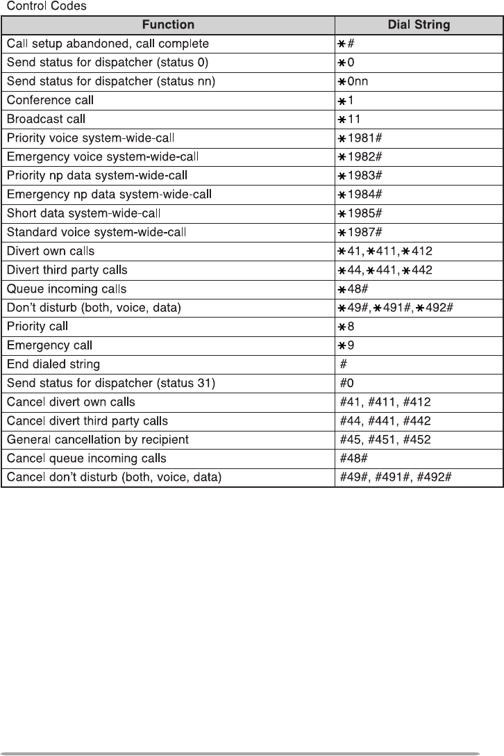
APPENDIX
gnilaiDtigiD2
noitcnuF gnirtSlaiD
rebmunlaudividnI98~02
rebmunpuorG99~09
gnilaiDtigiD3
noitcnuF gnirtSlaiD
rebmunlaudividnI998~002
rebmunpuorG899~009
rotarepoycnegremE999,211
slennahcnepoehtretnE011~101
secivresrotarepokrowteN ,171,161,151,141,131,121,111,001 191,181
gnilaiDtigiD4
noitcnuF gnirtSlaiD
llacXBAP9998~0001
gnilaiDtigiD5
noitcnuF gnirtSlaiD
)sllacdrowsserddaelgniS(llacXBAP +)6~3(gnirtstsriF )9998~0001(gnirtsdnoceS
)locotorpgnisserddadednetxE(llacXBAP +)8ro,7,0(gnirtstsriF )9999~0000(gnirtsdnoceS
gnilaiDtigiD6
noitcnuF gnirtSlaiD
llaclaudividniteelf-retnIxiferpnommoC +)0506~1002(#teelF )98~02(#laudividnI
llacpuorgteelf-retnIxiferpnommoC )99~09(#puorG+)0506~1002(#teelF
)locotorpgnisserddadednetxe(llacXBAP +)8ro,7,0(gnirtstsriF )99999~00000(gnirtsdnoceS

16
gnilaiDtigiD7
noitcnuF gnirtSlaiD
llaclaudividniteelf-retnIxiferpnommoC +)0506~1002(#teelF )998~002(#laudividnI
llacpuorgteelf-retnIxiferpnommoC +)0506~1002(#teelF )899~009(#puorG
)locotorpgnisserddadednetxe(llacXBAP +)8ro,7,0(gnirtstsriF )999999~000000(gnirtsdnoceS
gnilaiDtigiD8
noitcnuF gnirtSlaiD
llacNTSP +)0(gnirtstsriF )9999999~0000000(gnirtsdnoceS
)locotorpgnisserddadednetxe(llacXBAP +)8ro7(gnirtstsriF )9999999~0000000(gnirtsdnoceS
gnilaiDtigiD9
noitcnuF gnirtSlaiD
llaclaudividniteelf-retnIxiferp-retnI #teelF+)723~002(#xiferP )98~02(#laudividnI+)0506~1002(
llacpuorgteelf-retnIxiferp-retnI #teelF+)723~002(#xiferP )99~09(#puorG+)0506~1002(
llacNTSP +)0(gnirtstsriF )99999999~00000000(gnirtsdnoceS
)locotorpgnisserddadednetxe(llacXBAP +)8ro7(gnirtstsriF )99999999~00000000(gnirtsdnoceS
gnilaiDtigiD01
noitcnuF gnirtSlaiD
llaclaudividniteelf-retnIxiferp-retnI #teelF+)723~002(#xiferP )998~002(#laudividnI+)0506~1002(
llacpuorgteelf-retnIxiferp-retnI #teelF+)723~002(#xiferP )899~009(#puorG+)0506~1002(
llacNTSP +)0(gnirtstsriF gnirtsdnoceS)999999999~000000000(
gnilaiDtigiD11
noitcnuF gnirtSlaiD
llacNTSP +)0(gnirtstsriF gnirtsdnoceS)9999999999~0000000000(
17