Kenwood USA 31251110 AMATEUR TRANSMITTER WITH SCANNING RECEIVER User Manual 00 Cover
Kenwood USA Corporation AMATEUR TRANSMITTER WITH SCANNING RECEIVER 00 Cover
UserManual.wiki
>
Kenwood USA
>
31251110 User Manual
MANUAL
Navigation menu
Upload a User Manual
Namespaces
Wiki Guide
HTML
PDF
Info
Views
User Manual
Discussion / Help
Navigation
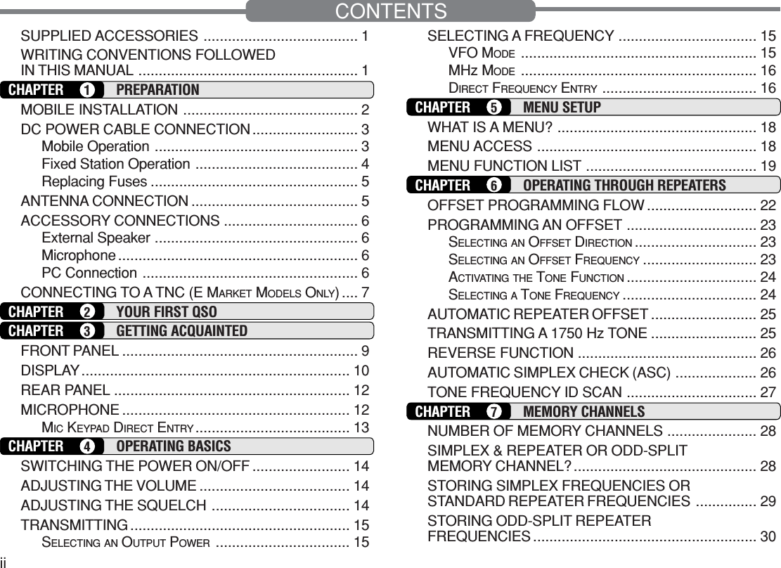
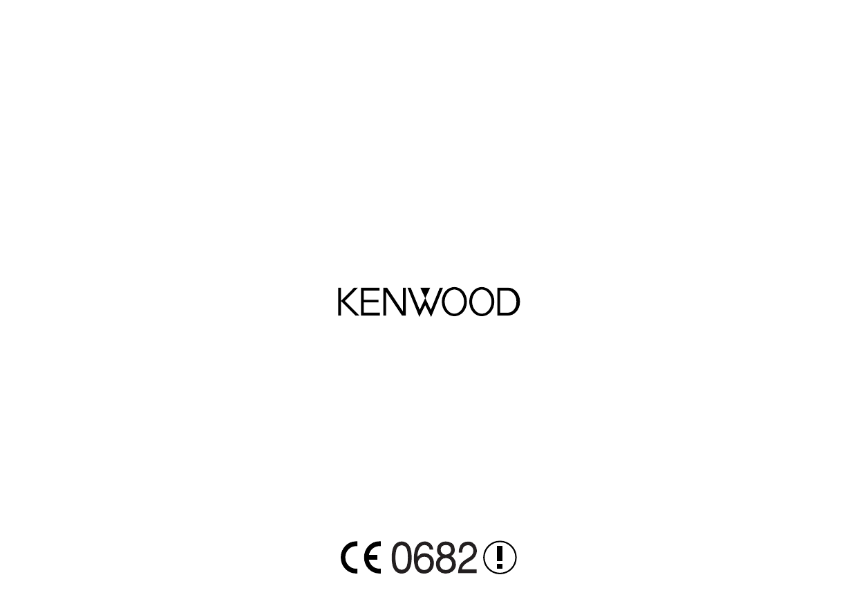
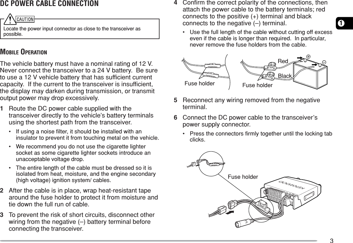
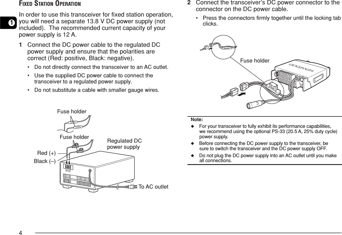
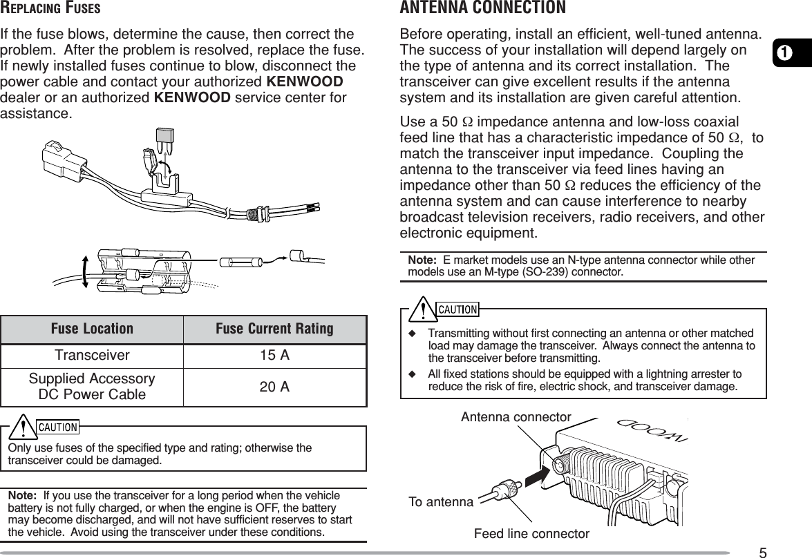
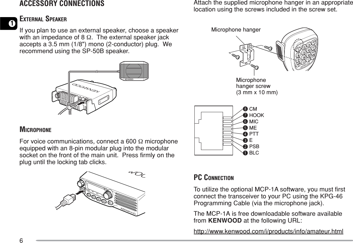
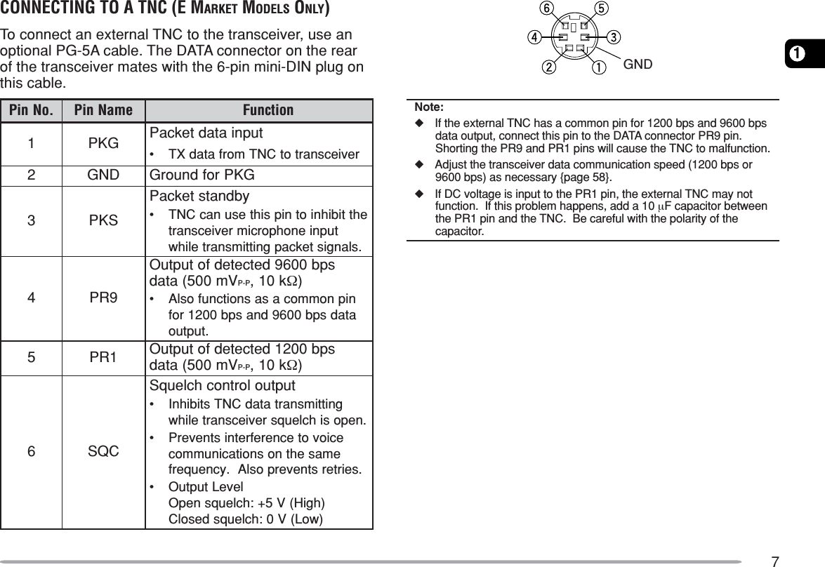
![1SUPPLIED ACCESSORIESAfter carefully unpacking the transceiver, identify theitems listed in the table below. We recommend you keepthe box and packaging for shipping.A market area code (K, E, or M2) can be found on thelabel attached to the package box.yrosseccA rebmuNtraP ytQenohporciMtekram2M)03-CMK( XX-4260-19T1tekramE,K)23-CMK( XX-1460-19TrewopCDelbactekram2M,KXX-1112-03E 1tekramEXX-2543-03EesuF tekram2M,KXX-7100-15F 1tekramEXX-4200-25FtekcarbgnitnuoMXX-2660-92J1regnahenohporciMXX-4851-91J1teswercSXX-5930-99N1)ylnotekramE,K(dracytnarraW—1launamnoitcurtsnIXX-8371-26B1WRITING CONVENTIONS FOLLOWED IN THIS MANUALThe writing conventions described below have beenfollowed to simplify instructions and avoid unnecessaryrepetition.noitcurtsnI odottahWsserP ]YEK[ .esaelerdnasserP YEK .sserP)s1(]YEK[ .dlohdnasserP YEK rodnoces1rof.regnolsserP]1YEK[ ,]2YEK[ .sserP 1YEK esaeler,yliratnemom1YEK sserpneht, 2YEK .sserP]2YEK[+]1YEK[ .dlohdnasserP 1YEK sserpneht,2YEK owtnahteromeraerehtfI.niyekhcaedlohdnasserp,syekneebsahyeklanifehtlitnunrut.desserpsserP][+]YEK[ .,FFOrewopreviecsnartehthtiWdlohdnasserp YEK ehtnrutneht,gnisserpybNOrewopreviecsnart][ .)hctiwSrewoP(](https://usermanual.wiki/Kenwood-USA/31251110/User-Guide-360246-Page-7.png)
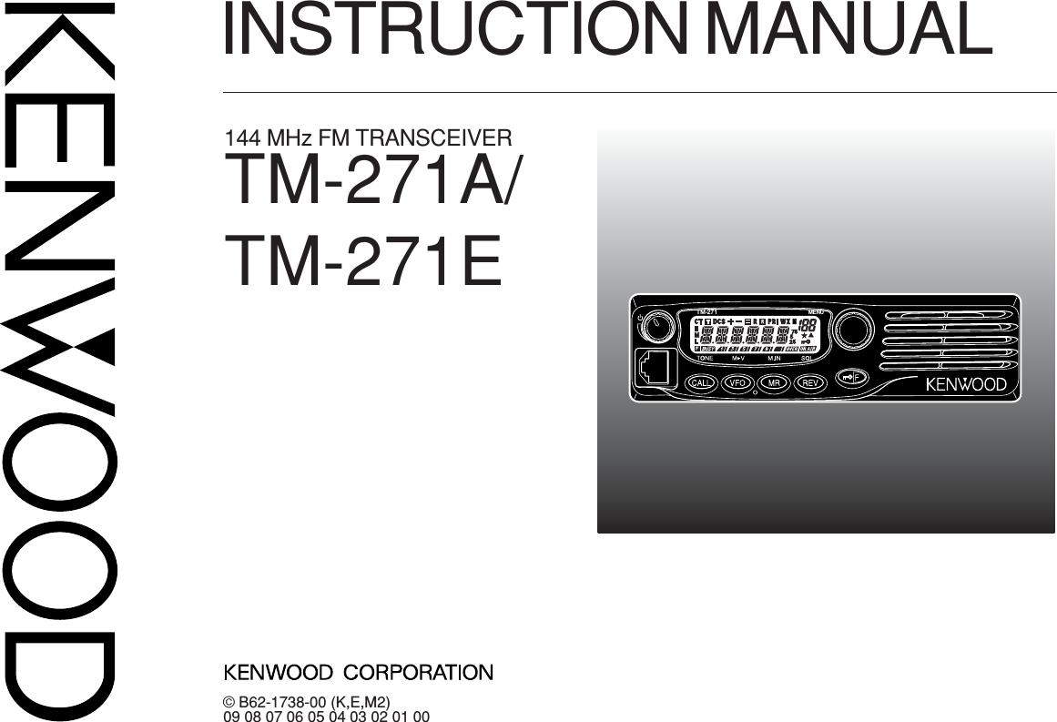
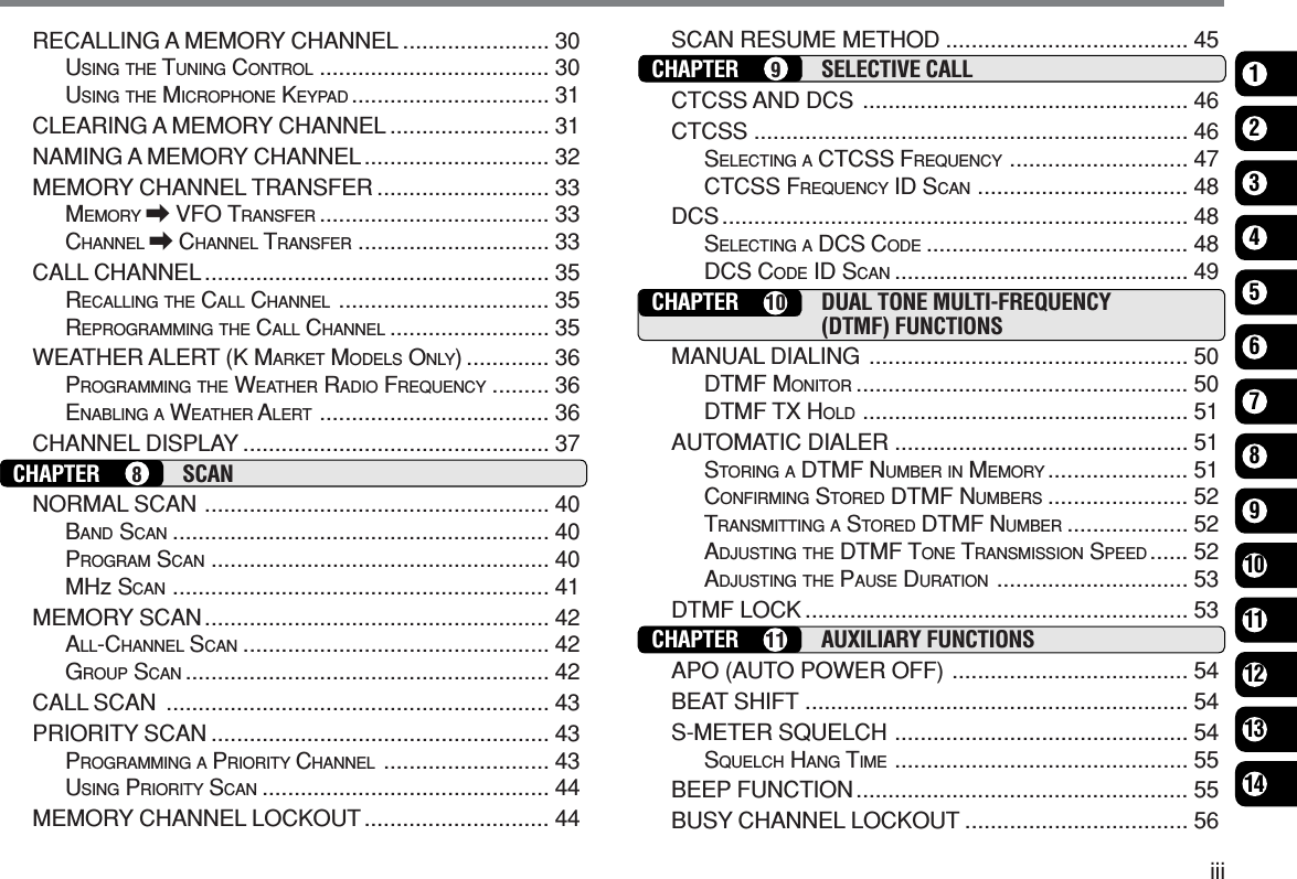
![82YOUR FIRST QSOAre you ready to give your transceiver a quick try?Reading this section should get your voice on theair right away. The instructions below are intendedonly as a quick guide. If you encounter problemsor there is something you would like to know more,read the detailed explanations given later in thismanual.YOUR FIRST QSOqPress [ ] (Power) briefly to switch the transceiverpower ON.•A high pitched double beep sounds and a Power-onmessage appears momentarily. The various indicatorsand the current operating frequency appear on the LCD.•The transceiver stores the current parameters when it isturned OFF and automatically recalls those parametersthe next time you turn the transceiver ON.wTurn the Volume control clockwise, to the 9 o’clockposition.eTurn the Tuning control to select a receptionfrequency.•You may further turn the Volume control to adjust thevolume level of the signal.rTo transmit, hold the microphone approximately 5 cm(2 inches) from your mouth.tPress and hold Mic [PTT], then speak in your normaltone of voice.yRelease Mic [PTT] to receive.uRepeat steps r, t, and y to continuecommunication.TM-271 MENUqw ety](https://usermanual.wiki/Kenwood-USA/31251110/User-Guide-360246-Page-14.png)
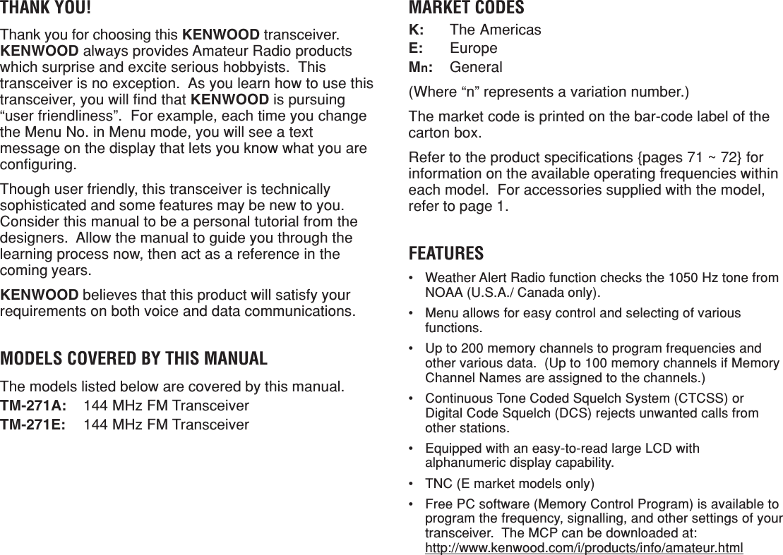
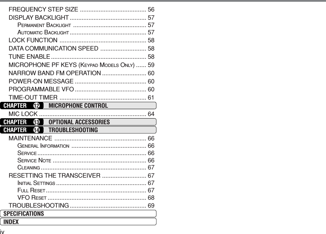
![93GETTING ACQUAINTEDFRONT PANELNote: This section describes only the main functions of the frontpanel controls. Explanations for functions not described here areprovided in the appropriate sections of this instruction manual.q we r t y uTM-271MENUqqqqq (Power) switch/ Volume controlPress to switch the transceiver power ON or OFF{page 14}.Turn to adjust the level of the receive audio from thespeaker {page 14}.wwwwwMENU button/ Tuning controlPress to enter MHz Mode {page 16}. In this mode,you can change the operating frequency in 1 MHzsteps using the Tuning control or Mic [UP]/[DWN].Press and hold for 1 second while in VFO Mode tobegin MHz Scan {page 41} or while in MR Mode tobegin Group Scan {page 42}.Press [F] then press [MENU] to enter Menu Mode{page 18}.Turn to select:•Operating frequencies when in VFO Mode {page 15}.•Memory Channels when in Memory Recall Mode{page 30}.•Menu Nos. when in Menu Mode {page 18}.•Scan direction while scanning {pages 27, 39, 47, 49}.eeeeeCALL keyPress to recall the Call Channel {page 35}. Pressand hold for 1 second while in VFO Mode to beginCall/VFO Scan {page 43}. Press and hold for1 second while in Memory Recall Mode to begin Call/Memory Scan {page 43}.Press [F] then press [CALL] to activate the Tone{page 24}, CTCSS {page 46}, or DCS {page 48}function.rrrrrVFO keyPress to enter VFO Mode {page 15}. In this mode,you can change the operating frequency using theTuning control or Mic [UP]/[DWN]. Press and holdfor 1 second while in VFO Mode to begin Band Scan{page 40}. Press and hold for 1 second while in VFOMode after programming a scan range to beginProgram Scan {page 40}.](https://usermanual.wiki/Kenwood-USA/31251110/User-Guide-360246-Page-15.png)
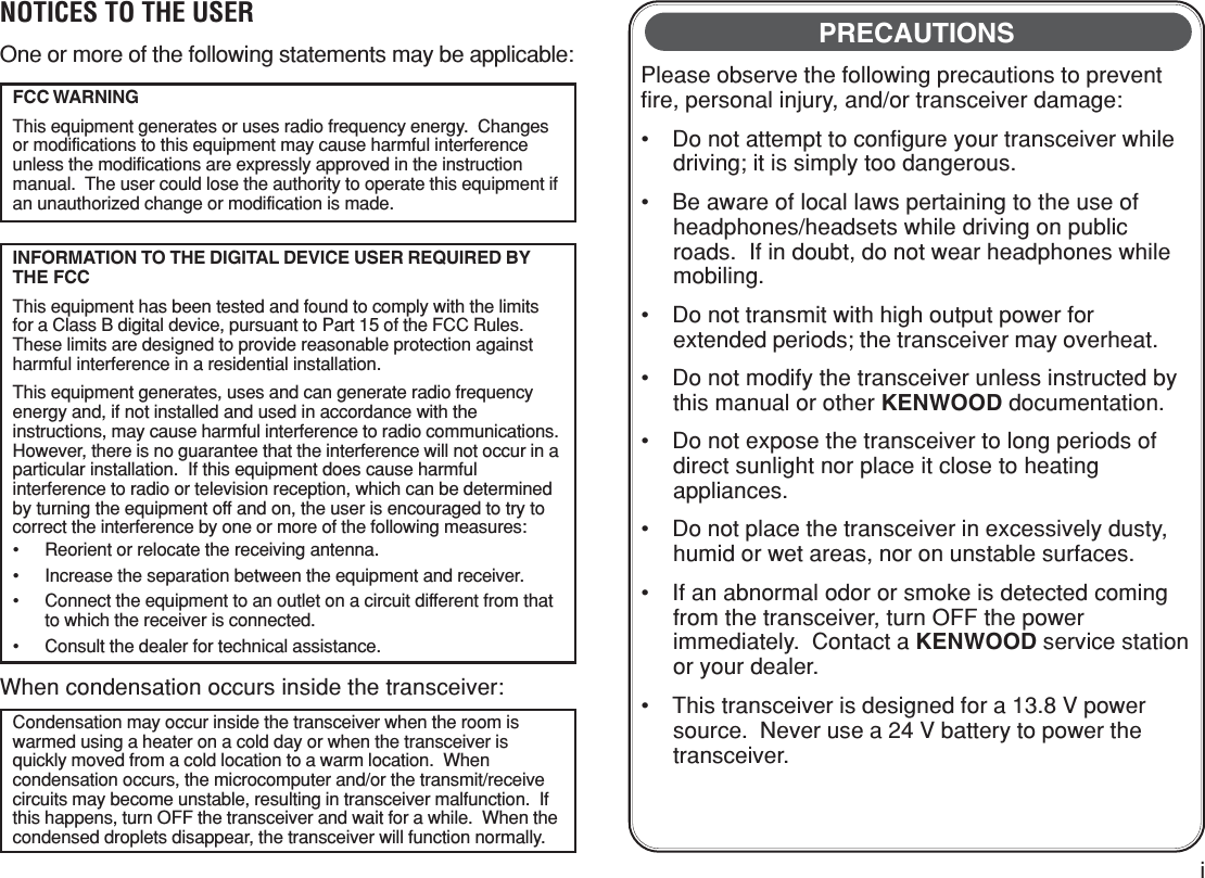
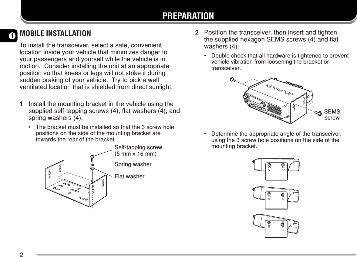
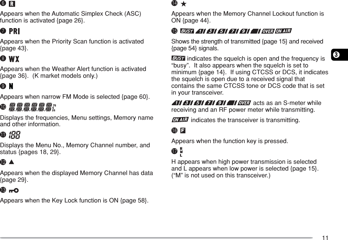
![103In MR Mode, press [F] then press [VFO] to transferthe contents of the selected Memory Channel to theVFO {page 33}.tttttMR keyPress to enter Memory Recall Mode {page 30}. Inthis mode, you can change memory channels usingthe Tuning control or Mic [UP]/[DWN]. Press andhold for 1 second while in Memory Recall Mode tobegin Memory Scan {page 42}.Press [F] then press [MR] to reprogram the CallChannel or a Memory Channel.yyyyyREV keyPress to switch the transmit frequency and receivefrequency when operating with an offset {page 23} oran odd-split Memory Channel {page 28}.Press [F] then press [REV] and rotate the Tuningcontrol to increase or decrease the squelch level.uuuuu/F keyPress and hold for 1 second to lock the transceiverkeys.Press momentarily to access the second functions ofthe transceiver keys.DISPLAYiuytrqwe!1!2!4 !3o!5!6!7!0qAppears when the CTCSS function is activated {page 46}.w Appears when the Tone function is activated {page 24}.eAppears when the DCS function is activated {page 48}.rAppears when the repeater shift function is activated{pages 23, 30}. (“ ” is not used on this transceiver.)tAppears when the Reverse function is activated {page 26}.](https://usermanual.wiki/Kenwood-USA/31251110/User-Guide-360246-Page-16.png)
![123REAR PANELq w e rqqqqqAntenna connectorConnect an external antenna {page 5} here. Whenmaking test transmissions, connect a dummy load inplace of the antenna. The antenna system or loadshould have an impedance of 50 Ω.Note: E market models use an N-type antenna connector whileother models use an M-type (SO-239) connector.wwwwwData cable (E market versions only)Connect this cable to a TNC {page 7}.eeeeePower Input 13.8 V DC cableConnect a 13.8 V DC power source here. Use thesupplied DC power cable {pages 3, 4}.rrrrrSP (speaker) jackIf desired, connect an optional external speaker forclearer audio. This jack accepts a 3.5 mm (1/8")mono (2-conductor) plug. See page 6.MICROPHONEqqrtyuiweqqqqqPTT (Push-to-Talk) switchPress and hold to transmit. Release to receive.wwwwwDWN/ keyPress to lower the operating frequency, MemoryChannel number, Menu Number, etc. Hold down torepeat the action. Also press to switch betweenvalues for functions with multiple choices. Press andhold Mic [PTT], then press [DWN/ ] to transmit .eeeeeUP/ keyPress to raise the operating frequency, MemoryChannel number, Menu Number, etc. Hold down torepeat the action. Also press to switch betweenvalues for functions with multiple choices. Press andhold Mic [PTT], then press [UP/ ] to transmit .KMC-32 KMC-30](https://usermanual.wiki/Kenwood-USA/31251110/User-Guide-360246-Page-18.png)
![133rrrrrCALL/A keyIdentical to the front panel CALL key. This key canbe reprogrammed if desired {page 59}. Press andhold Mic [PTT], then press [CALL/A] to transmit A.tttttVFO/B keyIdentical to the front panel VFO key. This key can bereprogrammed if desired {page 59}. Press and holdMic [PTT], then press [VFO/B] to transmit B.yyyyyMR/C keyIdentical to the front panel MR key. This key can bereprogrammed if desired {page 59}. Press and holdMic [PTT], then press [MR/C] to transmit C.uuuuuPF/D keyThe default function of this key is 1 MHz step. Thiskey can be reprogrammed if desired {page 59}.Press and hold Mic [PTT], then press [PF/D] totransmit D.iiiiiDTMF keypadThis 16-key keypad is used for DTMF functions{page 50} or to directly enter an operating frequency{page 16}, or a Memory Channel number {page 30}.The keypad can also be used to program a MemoryChannel name, Power-on message, or othercharacter strings {page 63}.MIC KEYPAD DIRECT ENTRYThe microphone keypad (keypad models only) allowsyou to make various entries depending on which modethe transceiver is in.In VFO or Memory Recall mode, use the Mic keypad toselect a frequency {page 16} or Memory Channelnumber {page 30}. First press the Mic PF key assignedthe ENTER function {page 59}.To manually send a DTMF number, press and hold Mic[PTT], then press the DTMF keys on the Mic keypad{page 50} in sequence.You can also use the Mic keypad to program a MemoryChannel name, Power-on message, or other characterstrings {page 63}.](https://usermanual.wiki/Kenwood-USA/31251110/User-Guide-360246-Page-19.png)
![144OPERATING BASICSSWITCHING THE POWER ON/OFF1Press [ ] (Power) to switch the transceiver power ON.•A high pitched double beep sounds and a Power-onmessage {page 60} appears briefly, followed by thefrequency and other indicators.2To switch the transceiver OFF, press [ ] (Power) (1s).•When you turn the transceiver OFF, a low pitcheddouble beep sounds.•The transceiver stores the current frequency andparameters when it is turned OFF and recalls theseparameters the next time you turn the transceiver ON.ADJUSTING THE VOLUMETurn the Volume control clockwise to increase the audiooutput level and counterclockwise to decrease the outputlevel.•If you are not receiving a signal, press the Mic PF keyassigned the MONI function {page 59}, then adjust theVolume control to a comfortable audio output level. Pressthe MONI key again to cancel the Monitor function.ADJUSTING THE SQUELCHThe purpose of Squelch is to mute the speaker when nosignals are present. With the squelch level correctly set,you will hear sound only while actually receiving signals.The higher the selected squelch level, the stronger thesignals must be to receive.The appropriate squelch level depends on the ambientRF noise conditions.1Press [F], [REV].•The current squelch level appears.2Turn the Tuning control to adjust the level.•Select the level at which the background noise is justeliminated when no signal is present.•The higher the level, the stronger the signals must be toreceive.•10 different levels can be set.(0: Minimum ~ 9: Maximum; 1 is the default value)3Press any key other than [ ] (Power) to store thenew setting and exit the squelch adjustment.](https://usermanual.wiki/Kenwood-USA/31251110/User-Guide-360246-Page-20.png)
![154TRANSMITTING1To transmit, hold the microphone approximately 5 cm(2 inches) from your mouth, then press and hold Mic[PTT] and speak into the microphone in your normaltone of voice.•“ ” and the RF Power meter appears. The RFPower meter shows the relative transmit output power().•If you press Mic [PTT] while you are outside thetransmission coverage, a high pitched error beepsounds.2When you finish speaking, release Mic [PTT].Note: If you continuously transmit for longer than the time specified inMenu No. 21 (default is 10 minutes) {page 62}, the internal time-outtimer generates a warning beep and the transceiver stops transmitting.In this case, release Mic [PTT] and let the transceiver cool down for awhile, then press Mic [PTT] again to resume transmission.SELECTING AN OUTPUT POWERYou can configure different power levels for transmission.1Press [F], [MENU] and turn the Tuning control toselect Menu No. 6 (TXP).2Press [MENU] and turn the Tuning control to select“H” (high; default) or “L” (low) power.3Press [MENU] to store the setting or any other key tocancel.4Press any key other than [MENU] to exit Menu Mode.◆Do not transmit at high output power for an extended period oftime. The transceiver could overheat and malfunction.◆Continuous transmission causes the heat sink to overheat. Nevertouch the heat sink when it may be hot.Note: When the transceiver overheats because of ambient hightemperature or continuous transmission, the protective circuit mayfunction to lower transmit output power.SELECTING A FREQUENCYVFO MODEThis is the basic mode for changing the operatingfrequency. To enter VFO Mode, press [VFO].Turn the Tuning control clockwise to increase thefrequency and counterclockwise to decrease thefrequency, or use Mic [UP]/[DWN].](https://usermanual.wiki/Kenwood-USA/31251110/User-Guide-360246-Page-21.png)
![164MHZ MODEIf the desired operating frequency is far away from thecurrent frequency, it is quicker to use the MHz TuningMode.To adjust the MHz digit:1While in VFO or Call Mode, press [MENU].•The MHz digit blinks.2Turn the Tuning control to select the desired MHzvalue.3Press any key to set the selected frequency andreturn to normal VFO Mode.4Continue adjusting the frequency as necessary, usingthe Tuning control or Mic [UP]/[DWN].DIRECT FREQUENCY ENTRYIn addition to turning the Tuning control or pressing Mic[UP]/[DWN], there is another way to select thefrequency. When the desired frequency is far away fromthe current frequency, you can directly enter a frequencyusing the Mic keypad (keypad models only).1Press [VFO].•You must be in VFO mode to make a direct frequencyentry.2Press the Mic PF key assigned the ENTER function{page 59}.3Press the numeric keys ([0] to [9]) to enter yourdesired frequency.•Pressing Mic [Enter] fills all remaining digits (the digitsyou did not enter) with 0 and completes the entry. Forexample, to select 145.000 MHz, press [1], [4], [5] andpress Mic [Enter] to complete the entry.•If you want to revise the MHz digits only, leaving the kHzdigits as they are, press Mic [VFO] in place of [Enter].](https://usermanual.wiki/Kenwood-USA/31251110/User-Guide-360246-Page-22.png)
![174Example 1To enter 145.750 MHz:Key in Display[Enter] – –– –––[1], [4], [5] 1 4 5. – – –[7], [5], [0] 1 4 5. 7 5 0Example 2To enter 145.000 MHz:Key in Display[Enter] – –– –––[1], [4], [5] 1 4 5. – – –[Enter] 1 4 5. 0 0 0Example 3To change 144.650 MHz to 145.650 MHz:Key in Display1 4 4. 6 5 0[Enter] – –– –––[1], [4], [5] 1 4 5. – – –Mic [VFO] 1 4 5. 6 5 0Note: If the entered frequency does not match the current frequencystep size, the frequency is automatically rounded down to the nextavailable frequency. When the desired frequency cannot be enteredexactly, confirm the frequency step size {page 56}.](https://usermanual.wiki/Kenwood-USA/31251110/User-Guide-360246-Page-23.png)
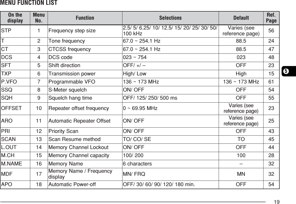
![185MENU SETUPWHAT IS A MENU?Many functions on this transceiver are selected orconfigured via a software-controlled Menu rather thanthrough the physical controls of the transceiver. Onceyou become familiar with the Menu system, you willappreciate its versatility. You can customize the varioustimings, settings, and programming functions on thistransceiver to meet your needs without using manycontrols and switches.MENU ACCESS1Press [F], [MENU].•A brief explanation of the menu, and the setting andMenu No. appear on the display.Menu Name Setting Menu Number2Turn the Tuning control to select your desired Menu.•As you change the Menu No., a brief explanation ofeach menu appears along with its current parameter.3Press [MENU] to configure the parameter of thecurrently selected Menu No.4Turn the Tuning control to select your desiredparameter.5Press [MENU] to store the new setting or any otherkey to cancel.6Press any key other than [MENU] to exit Menu Mode.](https://usermanual.wiki/Kenwood-USA/31251110/User-Guide-360246-Page-24.png)
![236PROGRAMMING AN OFFSETYou must first select an amateur radio repeater downlinkfrequency as described in “SELECTING AN OFFSETFREQUENCY”.SELECTING AN OFFSET DIRECTIONSelect whether the transmit frequency will be higher (+)or lower (–) than the receive frequency.1Press [F], [MENU] and turn the Tuning control toselect Menu No. 5 (SFT).2Press [MENU] and turn the Tuning control to select“+” or “–”.3Press [MENU] to store the setting or any other key tocancel.4Press any key other than [MENU] to exit Menu Mode.•“+” or “–” appears above the frequency, indicating whichoffset direction is selected.If the offset transmit frequency falls outside the allowablerange, transmission is inhibited. In this case, adjust thereception frequency so that the transmit frequency iswithin the band limits or change the offset direction.Note: While using an odd-split memory channel or transmitting, youcannot change the offset direction.SELECTING AN OFFSET FREQUENCYTo access a repeater which requires an odd-splitfrequency pair, change the offset frequency from thedefault which is used by most repeaters. The defaultoffset frequency is 600 kHz.1Press [F], [MENU] and turn the Tuning control toselect Menu No. 10 (OFFSET).2Press [MENU] and turn the Tuning control to selectthe appropriate offset frequency.•The selectable range is from 0.00 MHz to 69.95 MHz insteps of 50 kHz.3Press [MENU] to store the setting or any other key tocancel.4Press any key other than [MENU] to exit Menu Mode.Note: After changing the offset frequency, the new offset frequencywill also be used by Automatic Repeater Offset.](https://usermanual.wiki/Kenwood-USA/31251110/User-Guide-360246-Page-29.png)
![246ACTIVATING THE TONE FUNCTIONTo activate Tone, press [F], [CALL].•As you press [F], [CALL], the selection cycles as follows:“OFF” ➞ “TONE” ➞ “CTCSS” ➞ “DCS” ➞ “OFF”.•“T” appears on the upper part of display, indicating that theTone function is activated.Note: You cannot use the Tone function and CTCSS/ DCS functionssimultaneously. Switching the Tone function ON after having activatedthe CTCSS/ DCS functions deactivates the CTCSS/ DCS functions.E market version only: When you access repeaters that require a1750 Hz tone, you do not need to activate the Tone function. Simplypress [CALL] without pressing Mic [PTT] to transmit a 1750 Hz tone(default setting).SELECTING A TONE FREQUENCY1Press [F], [MENU] and turn the Tuning control toselect Menu No. 2 (T).2Press [MENU] and turn the Tuning control to selectthe desired tone frequency (default is 88.5 Hz).3Press [MENU] to store the setting or any other key tocancel.4Press any key other than [MENU] to exit Menu Mode.Available Tone Frequencies)zH(seicneuqerFenoT240.764.582.7015.6318.3711.8123.965.889.0113.1419.9717.5229.175.198.4112.6412.6811.9224.478.498.8114.1518.2916.3320.774.790.3217.6515.3028.1427.970.0013.7212.2615.6023.0525.285.3018.1319.7617.0121.452Note: 42 different tones are available for the transceiver. These42 tones includes 37 EIA standard tones and 5 non-standard tones.E market version only:◆To transmit a 1750 Hz tone, simply press [CALL] without pressingMic [PTT] (default setting). Release [CALL] to quit transmitting.You can also make the transceiver remain in the transmit mode for2 seconds after releasing [CALL]; a 1750 Hz tone is notcontinuously transmitted. Access Menu No. 20 (HLD) and select“ON”.◆To use [CALL] for recalling the Call Channel in place oftransmitting a 1750 Hz tone, access Menu No. 19 (CK) and select“CALL”.](https://usermanual.wiki/Kenwood-USA/31251110/User-Guide-360246-Page-30.png)
![256AUTOMATIC REPEATER OFFSETThis function automatically selects an offset direction,according to the frequency on the VHF band. Thetransceiver is programmed for an offset direction asshown below. To obtain an up-to-date band plan forrepeater offset direction, contact your national AmateurRadio association.K market version only+––– +SSSS144.0 145.5 146.4 147.0 147.6145.1 146.0 146.6 147.4 148.0 MHzS: SimplexThis complies with the standard ARRL band plan.E market version onlySSS: Simplex–144.0 146.0 MHz145.8145.6Note: Automatic Repeater Offset does not function when the Reversefunction is ON. However, pressing [REV] after Automatic RepeaterOffset has selected an offset (split) status, exchanges the receive andtransmit frequencies.1Press [F], [MENU] and turn the Tuning control toselect Menu No. 11 (ARO).2Press [MENU] and turn the Tuning control to switchthe function “ON” (default) or “OFF”.3Press [MENU] to store the setting or any other key tocancel.4Press any key other than [MENU] to exit Menu Mode.TRANSMITTING A 1750 Hz TONEMost of the repeaters in Europe require the transceiverto transmit a 1750 Hz tone. On E market versions,simply pressing [CALL] causes the transceiver totransmit a 1750 Hz tone. (On other market versions,pressing [CALL] changes the transceiver to the CallChannel {page 35}.)To change the setting of the CALL key:1Press [F], [MENU] and turn the Tuning control toselect Menu No. 19 (CK).2Press [MENU] and turn the Tuning control to select“CALL” or “1750”.3Press [MENU] to store the setting or any other key tocancel.4Press any key other than [MENU] to exit Menu Mode.Some repeaters in Europe must receive continuoussignals for a certain period of time, following a 1750 Hztone. This transceiver is also capable of remaining in thetransmit mode for 2 seconds after transmitting the tone.1Press [F], [MENU] and turn the Tuning control toselect Menu No. 20 (HLD).2Press [MENU] and turn the Tuning control to select“ON”.3Press [MENU] to store the setting or any other key tocancel.4Press any key other than [MENU] to exit Menu Mode.](https://usermanual.wiki/Kenwood-USA/31251110/User-Guide-360246-Page-31.png)
![266REVERSE FUNCTIONThe reverse function exchanges a separate receive andtransmission frequency. So, while using a repeater, youcan manually check the strength of a signal that youreceive directly from the other station. If the station’ssignal is strong, both stations should move to a simplexfrequency and free up the repeater. To swap the transmit and receive frequencies:Press [REV] to switch the Reverse function ON (orOFF).• “R” appears when the function is ON.Note:◆You can turn the Reverse function ON when you are operating inSimplex Mode. However, it does not change the Transmission/Reception frequencies.◆If pressing [REV] places the reception frequency outside theallowable range, an error tone sounds and the function does notoperate.◆If pressing [REV] places the transmission frequency outside theallowable range, pressing Mic [PTT] causes an error tone tosound and transmission is inhibited.◆You cannot switch Reverse ON or OFF while transmitting.AUTOMATIC SIMPLEX CHECK (ASC)While using a repeater, the ASC function periodicallychecks the strength of the signal you are receiving fromthe other station. If the station’s signal is strong enoughto allow direct contact without a repeater, the “ ”indicator starts blinking.Press [REV] (1s) to switch the function ON (or OFF).•“ ” appears when the function is ON.•While direct contact is possible, “ ” blinks.REV ON144.725 MHz145.325 MHz144.725 MHzTX: 144.725 MHz TX: 144.725 MHzRX: 145.325 MHz RX: 145.325 MHzTX: 144.725 MHz TX: 145.325 MHzRX: 145.325 MHz RX: 144.725 MHz](https://usermanual.wiki/Kenwood-USA/31251110/User-Guide-360246-Page-32.png)
![276Note:◆Pressing [PTT] causes the “ ” icon to quit blinking.◆ASC can be activated while operating in Simplex mode. However,it does not change the Transmission/Reception frequencies.◆ASC does not function while scanning.◆Activating ASC while using Reverse switches Reverse OFF.◆If you recall a Memory Channel or the Call Channel that containsa Reverse ON status, ASC is switched OFF.◆ASC causes received audio to be momentarily intermitted every3 seconds.TONE FREQUENCY ID SCANThis function scans through all tone frequencies to identifythe incoming tone frequency on a received signal. Youcan use this function to determine which tone frequency isrequired by accessing your local repeater.1Press [F], [MENU] and turn the Tuning control toselect Menu No. 2 (T).2Press [MENU] (1s) to start the Tone Frequency IDScan.•When the transceiver receives a signal, scan starts.The decimal point blinks during scan.•While the transceiver is receiving a signal during ToneFrequency ID Scan, the signal is emitted from thespeaker.•To reverse the scan direction, turn the Tuning control.•To quit the function, press any key.•When the tone frequency is identified, a beep soundsand the identified frequency blinks.3Press [MENU] to program the identified tonefrequency in place of the current tone frequency orpress any other key to exit the Tone Frequency IDScan.•Turn the Tuning control while the identified tonefrequency is blinking to resume scanning.4Press any key other than [MENU] to exit Menu Mode.Note:◆Some repeaters do not re-transmit the access tone in thedownload signal. In this case, check the other station’s uplinksignal to detect the repeater access tone.◆The transceiver continues to check the Weather Alert Channeland Priority Channel during Tone Frequency ID Scan.](https://usermanual.wiki/Kenwood-USA/31251110/User-Guide-360246-Page-33.png)
![287MEMORY CHANNELSIn Memory Channels, you can store frequencies andrelated data that you frequently use so that you do notneed to reprogram that data every time. You can quicklyrecall a programmed channel through simple operation.A total of 200 Memory Channels (100 when using theMemory Name function) are available for storingfrequencies, modes, and other operating conditions.NUMBER OF MEMORY CHANNELSThe transceiver must be configured to either 200Memory Channels without using the Memory Namefunction or 100 Memory Channels with the MemoryName function (default).To change the Memory Channel capacity:1Press [F], [MENU] and turn the Tuning control toselect Menu No. 15 (M.CH).2Press [MENU] and turn the Tuning control to selecteither “100” (default) or “200”.3Press [MENU].•“SURE ?” appears.4Press [MENU] to accept or press any other key tocancel.Note:◆If you change the Memory Channel capacity from 200 channels to100 channels after having stored data in channels 100 to 199, allMemory Channel data in channels 100 to 199 will be erased.◆If you change the Memory Channel capacity from 100 channels to200 channels after storing Memory Names in those channels, theMemory Name data will be erased.SIMPLEX & REPEATER OR ODD-SPLIT MEMORYCHANNEL?You can use each Memory Channel as a simplex &repeater channel or an odd-split channel. Store only onefrequency to use as a simplex & repeater channel or twoseparate frequencies to use as an odd-split channel.Select either application for each channel depending onthe operations you have in mind.Simplex & repeater channels allow:•Simplex frequency operation•Repeater operation with a standard offset (if an offsetdirection is stored)Odd-split channels allow:•Repeater operation with a non-standard offsetNote: Not only can you store data in Memory Channels, but you canalso overwrite existing data with new data.](https://usermanual.wiki/Kenwood-USA/31251110/User-Guide-360246-Page-34.png)
![297The data listed below can be stored in each MemoryChannel:retemaraP &xelpmiSretaepeR tilpS-ddOycneuqerfevieceR seY seYycneuqerftimsnarTseYycneuqerfenoTseYseYNOenoTseYseYycneuqerfSSCTCseYseYNOSSCTCseYseYedocSCDseYseYNOSCDseYseYnoitceridtesffOseYA/NycneuqerftesffOseYA/NNOesreveRseYA/NezispetsycneuqerFseYseYMFdnabworraNseYseYtfihStaeBseYseYtuokcollennahCyromeMseYseYemanlennahCyromeMseYseYYes: Can be stored in memory.N/A: Cannot be stored in memory.Note:◆Memory Channel Lockout cannot be set to the Program ScanMemory (L0/U0 ~ L2/U2), the Priority Channel (Pr), or theWeather Alert Channel (AL).◆Tone, CTCSS, and DCS are automatically turned OFF whensetting up the Weather Alert Channel (AL).STORING SIMPLEX FREQUENCIES OR STANDARDREPEATER FREQUENCIES1Press [VFO].2Turn the Tuning control to select your desiredfrequency.•You can also directly enter a desired frequency usingthe keypad {page 13}.3If storing a standard repeater frequency, select thefollowing data:•Offset direction {page 23}•Tone function, if necessary {page 24}•CTCSS/ DCS function, if necessary {pages 46, 48}If storing a simplex frequency, you may select otherrelated data (CTCSS or DCS settings, etc.).4Press [F].•A Memory Channel number appears and blinks.•“ ” appears if the channel contains data.](https://usermanual.wiki/Kenwood-USA/31251110/User-Guide-360246-Page-35.png)
![307•Memory Channel numbers L0/U0 ~ L2/U2 {page 40}, Pr{page 43}, and AL (Weather Alert) {page 36} (K marketmodels only) are reserved for other functions.5Turn the Tuning control or press Mic [UP]/[DWN] toselect the Memory Channel in which you want tostore the data.6Press [MR] to store the data to the channel.STORING ODD-SPLIT REPEATER FREQUENCIESSome repeaters use a pair of reception and transmissionfrequencies with a non-standard offset. If you store twoseparate frequencies in a Memory Channel, you canoperate on those repeaters without programming theoffset frequency and direction.1Store the desired reception frequency and relateddata by following steps 1 to 6 given for simplex orstandard repeater frequencies {page 29}.2Turn the Tuning control or press Mic [UP]/[DWN] toselect your desired transmit frequency.3Press [F].4Turn the Tuning control or press Mic [UP]/[DWN] toselect the pre-programmed reception MemoryChannel in which you want to store the data.5Press [MR] (1s).•The transmission frequency is stored in the memorychannel.Note:◆When you recall an odd-split memory channel, “+” and “–” appearon the display. To confirm the transmission frequency, press[REV].◆Transmit offset status and reverse status are not stored inodd-split memory channels.RECALLING A MEMORY CHANNELUSING THE TUNING CONTROL1Press [MR] to enter Memory Recall mode.•The Memory Channel last used is recalled.2Turn the Tuning control to select your desiredMemory Channel.•You cannot recall an empty Memory Channel.•To restore VFO mode, press [VFO].](https://usermanual.wiki/Kenwood-USA/31251110/User-Guide-360246-Page-36.png)
![317USING THE MICROPHONE KEYPADYou can also recall a Memory Channel by entering adesired Memory Channel number with the microphonekeypad.1Press [MR] to enter Memory Recall mode.2Press the microphone key assigned the ENTERfunction.3Enter the channel number using the microphonekeypad.•For single-digit channel numbers, enter “0” first or pressMic [Enter] after entering the channel number.•For two-digit channel numbers that begin with “1”, pressMic [Enter] after entering the channel number.Note:◆You cannot recall an empty Memory Channel. An error beepsounds.◆You cannot recall the Program Scan Memory Channels(L0/U0 ~ L2/U2), the Priority Channel (Pr), and the Weather AlertChannel (AL) (K market models only) using the numeric keypad.◆When you recall an odd-split memory channel, “+” and “–” appearon the display. Press [REV] to display the transmissionfrequency.◆After recalling a Memory Channel, you may modify data such asNarrow Band, Tone, or CTCSS. However, these settings arecleared once you select another channel or the VFO Mode. Topermanently store the data, overwrite the channel contents.CLEARING A MEMORY CHANNELTo erase an individual Memory Channel:1Recall the Memory Channel you want to erase.2Press [ ] (Power) (1s) to switch the transceiverOFF.3Press [MR]+[ ] (Power).•An erase confirmation message appears.4Press [MR] to erase the channel data.•The contents of the Memory Channel are erased.•To quit clearing the Memory Channel, press any keyother than [MR].Note:◆You can also clear the Priority Channel, the AL Channel, andL0/U0 ~ L2/U2 data. (The Call Channel cannot be cleared.)◆To clear all Memory Channel contents at once, perform Full Reset{page 67}.◆You cannot clear channels while in Channel Display Mode.](https://usermanual.wiki/Kenwood-USA/31251110/User-Guide-360246-Page-37.png)
![327NAMING A MEMORY CHANNELYou can name Memory Channels using up to 6alphanumeric characters. When you recall a namedMemory Channel, its name appears on the display inplace of the stored frequency. Names can be call signs,repeater names, cities, names of people, etc. In order touse the Memory Name function, the Memory Channelcapacity must be set to 100 channels. To change theMemory Channel capacity from 200 to 100, accessMenu No. 15 (M.CH) {page 28}.1Press [MR] and turn the Tuning control to recall yourdesired Memory Channel.2Press [F], [MENU] and turn the Tuning control toselect Menu No. 16 (M.NAME).3Press [MENU].•A blinking cursor appears.4Turn the Tuning control to select a desiredalphanumeric character.•You can enter the following alphanumeric characters:0 ~ 9, A ~ Z, – (hyphen), / (slash), and a space.•Rather than using the Tuning control, you can use theMic keypad (keypad models only) to enter alphanumericcharacters {page 64}.5Press [MR].•The cursor moves to the next digit.•To move to the previous digit, press [VFO]. To deletethe character at the current cursor position, press [F].6Repeat steps 4 and 5 to enter up to 6 digits.7Press [MENU] to complete the entry.•Press any key other than [MR], [VFO], [F], and [MENU]to cancel the entry.•To complete an entry of less than 6 characters, press[MENU] two times.8Press any key other than [MENU] to exit Menu Mode.After storing a Memory Name, the Memory Nameappears in place of the operating frequency. However,you can still display the operating frequency, if desired.To display the frequency rather than Memory Name,access Menu No. 17 (MDF) and select “FRQ”. Thismenu toggles the display mode between the MemoryName (“MN”) and frequency display (“FRQ”).Note:◆You cannot name the Call Channel {page 35}.◆You cannot assign a Memory Name to a channel that does notcontain data.◆You can overwrite stored names by repeating steps 1 to 8.◆The stored name is erased when you clear the Memory Channeldata.](https://usermanual.wiki/Kenwood-USA/31251110/User-Guide-360246-Page-38.png)
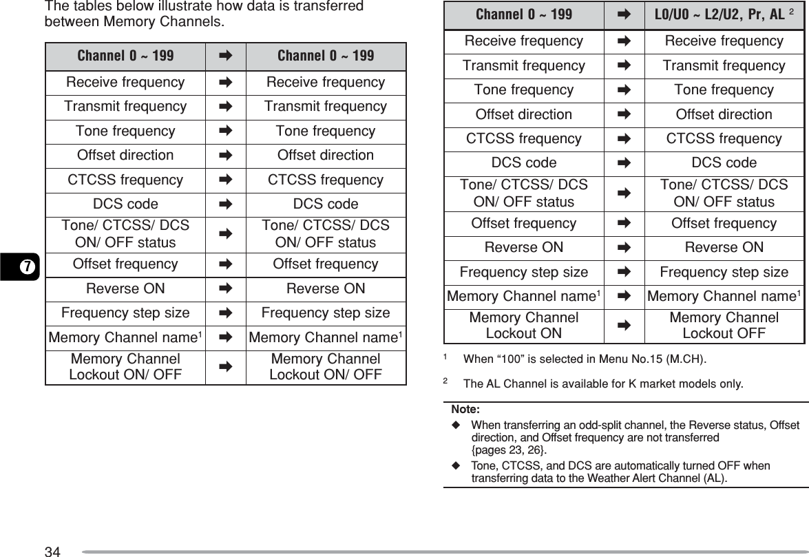
![337MEMORY CHANNEL TRANSFERMEMORY \ VFO TRANSFERAfter retrieving frequencies and associated data fromMemory Recall Mode, you can copy the data to the VFO.This function is useful, for example, when the frequencyyou want to monitor is near the frequency stored in aMemory Channel.1Press [MR], then turn the Tuning control or press Mic[UP]/[DWN] to recall the desired Memory Channel.•Alternatively, press [CALL] to select the Call Channel.2Press [F], [VFO] to copy the Memory Channel data tothe VFO.Note:◆To copy an odd-split channel data {page 30}, press [REV] beforeperforming the transfer.◆You can also transfer the Program Scan memory channels(L0/U0 ~ L2/U2), the Priority Channel (Pr), and the Weather AlertChannel (AL) (K market models only) to the VFO.◆Lockout status and Memory Names are not copied from aMemory Channel to the VFO.CHANNEL \ CHANNEL TRANSFERYou can copy channel information from one MemoryChannel to another. This function is useful when storingfrequencies and associated data that you temporarilychange in Memory Recall Mode.1Press [MR], then turn the Tuning control or press Mic[UP]/[DWN] to recall the desired Memory Channel.2Press [F].3Select the Memory Channel where you would like thedata copied by using the Tuning control or pressingMic [UP]/[DWN].4Press [MR].](https://usermanual.wiki/Kenwood-USA/31251110/User-Guide-360246-Page-39.png)
![357CALL CHANNELThe Call Channel can be recalled instantly no matterwhat frequency the transceiver is operating on. Forinstance, you may use the Call Channel as anemergency channel within your group. In this case, CallScan {page 43} will be useful.The default Call Channel frequency is 144.000 MHz.Note: Unlike Memory Channels 0 to 199, the Call Channel cannot becleared.RECALLING THE CALL CHANNEL1Press [CALL] to recall the Call Channel.•The Call Channel frequency and “C” appear.•To return to the previous frequency, press [CALL] again.REPROGRAMMING THE CALL CHANNEL1Select your desired frequency and related data (Tone,CTCSS, DCS, or offset direction, etc.).•When you program the Call Channel as an odd-splitchannel, select a reception frequency first.2Press [F].•A Memory Channel number appears and blinks.3Turn the Tuning control or press Mic [UP]/[DWN] toselect the Call Channel (“C”).4Press [MR].•The selected frequency and related data are stored inthe Call Channel.To also store a separate transmit frequency, continue with thefollowing steps:5Select the desired transmission frequency.6Press [F].7Turn the Tuning control or press Mic [UP]/[DWN] toselect the Call Channel (“C”).8Press [MR] (1s).•The separate transmission frequency is stored in theCall Channel.Note:◆When you recall an odd-split Call Channel, “+” and “–” appear onthe display.◆Transmit offset status and Reverse status are not stored in anodd-split Call Channel.](https://usermanual.wiki/Kenwood-USA/31251110/User-Guide-360246-Page-41.png)
![367WEATHER ALERT (K MARKET MODELS ONLY)Any of the NOAA Weather Radio channels can beprogrammed to the AL memory channel of thetransceiver. The transceiver can be configured to checkthe NOAA Weather Alert tone (1050 Hz) and willautomatically alert you by recalling and monitoring theWeather Radio frequency when the Weather Alert toneis broadcasted, and the “WX” icon will blink.PROGRAMMING THE WEATHER RADIO FREQUENCYThe transceiver is preprogrammed to 162.550 MHz(WX1). You can store a different frequency to the ALchannel to use this function. Refer to the NOAA channelfrequency directory for your local weather channelfrequency before you use the Weather Alert function.The latest Weather Radio information can be obtainedfrom http://www.nws.noaa.gov/nwr/.1Press [VFO].2Select your local NOAA Weather Radio channelfrequency using the Tuning control or Mic [UP]/[DWN].3Press [F].•A Memory Channel number appears and blinks.4Turn the Tuning control or press Mic [UP]/[DWN] toselect the Alert Channel (“AL”).5Press [MR].)zHM(seicneuqerFoidaRrehtaeW1XW 2XW 3XW 4XW 5XW 6XW 7XW055.261004.261574.261524.261054.261005.261525.261Note:◆When you perform Full Reset {page 63}, the Weather Radiofrequency recovers the factory default frequency (162.550 MHz).◆When you clear the Weather Radio (AL) Channel {page 31} (thesame as clearing a Memory Channel), the factory defaultfrequency (162.550 MHz) is recovered.◆The Weather Radio (AL) Channel can be programmed with aChannel Name {page 31}.◆You can also transfer the AL Memory Channel data to the VFO oranother Memory Channel.ENABLING A WEATHER ALERTYou can monitor the Weather Radio frequencycontinuously or in the background while receiving onanother frequency.To monitor the Weather Radio frequency continuously:1Press [F], [MENU] and turn the Tuning control toselect Menu No. 42 (WXA).2Press [MENU] and turn the Tuning control to select“ON”.3Press [MENU] to store the setting.•“WX” appears on the display.](https://usermanual.wiki/Kenwood-USA/31251110/User-Guide-360246-Page-42.png)
![3774Press any key other than [MENU] to exit Menu Mode.•The transceiver automatically changes to the ALchannel.•The Tone, CTCSS, and DCS functions cannot beconfigured to the AL channel.•Priority Scan is set to OFF automatically when theWeather Alert function is turned ON.5To exit Weather Alert Mode, press [MENU], selectMenu No. 42 (WXA), and set it to “OFF” (default).To monitor another frequency while monitoring theWeather Radio in the background:1Perform step 1 ~ 4, above.2Press [VFO] or [MR] and turn the Tuning control toselect another frequency or Memory Channel.•“WX” remains on the LCD.3When the Weather Alert tone is broadcasted, thetransceiver automatically switches to the AL channel.•“WX” blinks.4To exit Weather Alert Mode, press [MENU], selectMenu No. 42 (WXA), and set it to “OFF”.Note:◆The transceiver checks the weather alert tone once every secondwhile you are monitoring another frequency or channel.◆When a 1050 Hz tone is detected, the display will change to theAL channel, the Weather Alert tone sounds, and the “WX” iconblinks. Squelch remains open until the frequency is changed orthe transceiver power is turned OFF.◆If the transceiver is transmitting or receiving a signal on anotherfrequency, the Weather Alert function temporarily pauses.◆Turning the Beep function “OFF” does not disable the WeatherAlert tone.◆You cannot transmit on the AL channel while the Weather Alertfunction is ON.CHANNEL DISPLAYWhile in this mode, the transceiver displays only MemoryChannel numbers (or Memory Names if they have beenstored), instead of frequencies.1With the transceiver power OFF, press [REV]+[ ](Power) to turn the power ON.•The transceiver displays the Memory Channel numbersin place of the operating frequencies.2Turn the Tuning control to select your desiredMemory Channel number.](https://usermanual.wiki/Kenwood-USA/31251110/User-Guide-360246-Page-43.png)
![387While in Channel Display mode, you cannot activate thefollowing functions:•VFO Mode•VFO Scan•Call/VFO Scan•MHz Scan•Scan Direction•Memory Store•Memory to VFO Transfer•Memory to Memory Transfer•Clear Memory Channel•VFO Reset•Full Reset•1 MHz Step•Selection for Tone and Selective Call•Auto Simplex Checker•Menu ModeTo recover normal operation, turn the transceiver powerOFF and press [REV]+[ ] again.Note:◆To enter the Channel Display Mode, you must have at least oneMemory Channel that contains data.◆If the Memory Channel contains a Memory Name, the MemoryName is displayed in place of “CH”.](https://usermanual.wiki/Kenwood-USA/31251110/User-Guide-360246-Page-44.png)
![398SCANScan is a useful function for hands-off monitoring of yourfavorite frequencies. By becoming comfortable with alltypes of scan, you will increase your operating efficiency.This transceiver provides the following types of scans.epyTnacS esopruPlamroNnacSnacSdnaB ehtfodnaberitneehtsnacSdetcelesuoyycneuqerfmargorPnacSycneuqerfdeificepsehtsnacSyromeMniderotssegnar2U/2L~0U/0LslennahCnacSzHM anihtiwseicneuqerfehtsnacSegnarzHM1yromeMnacSlennahC-llAnacSslennahCyromeMllasnacS)99ot0morfro(991ot0morfnacSpuorGnislennahCyromeMsnacS,91~0(slennahc02fospuorg).cte,95~04,93~02llaCnacSOFV dnalennahCllaCehtsnacSycneuqerfOFVtnerrucehtyromeMlennahCdnalennahCllaCehtsnacSlennahCyromeMdetcelesehtnacSytiroirPehtnoseitivitcaehtskcehCyreve)rP(lennahCytiroirPsdnoces3Note:◆When the CTCSS or DCS function is activated, the transceiverstops at a busy frequency and decodes the CTCSS tone or DCScode. If the tone or code matches, the transceiver unmutes.Otherwise, it resumes scanning.◆Press and hold the Mic PF key programmed as MONI {page 59}to pause scan in order to monitor the scanning frequency.Release the key to resume scanning.◆Pressing and holding Mic [PTT] causes scan to stop (excludingPriority Scan).◆While scanning, you can change the scan frequency direction byturning the Tuning control or using the Mic [UP]/[DWN] keys.◆Starting scan switches OFF the Automatic Simplex Check (ASC){page 26}.◆Adjust the Squelch level before using Scan {page 14}. Selecting aSquelch level too low could cause Scan to stop immediately.](https://usermanual.wiki/Kenwood-USA/31251110/User-Guide-360246-Page-45.png)
![408NORMAL SCANWhen you are operating the transceiver in VFO Mode,3 types of scanning are available: Band Scan, ProgramScan, and MHz Scan.BAND SCANThe transceiver scans the entire band of the frequencyyou selected. For example, if you are operating andreceiving at 144.525 MHz, it scans all the frequenciesavailable for the VHF band. (Refer to receiver VFOfrequency range in the specifications {page 72}.) Whenthe current VFO receive frequency is outside the ProgramScan frequency range {below}, the transceiver scans theentire frequency range available for the current VFO.1Press [VFO] and turn the Tuning control or press Mic[UP]/[DWN] to select a frequency outside of theProgram Scan frequency range.2Press [VFO] (1s) to start Band Scan.•Scan starts from the current frequency.•The 1 MHz decimal blinks while scanning is in progress.3Press any key other than [F] or [ ] (Power) to stopBand Scan.Note:◆The transceiver scans the frequency range that is stored in MenuNo. 7 (P.VFO) {page 61}.◆If you select a frequency within the L0/U0 ~ L2/U2 range in step 2,Program Scan starts.PROGRAM SCANYou can limit the scanning frequency range. There are3 memory channel pairs (L0/U0 ~ L2/U2) available forspecifying the start and end frequencies. Program Scanmonitors the range between the start and endfrequencies that you have stored in these MemoryChannels. Before performing Program Scan, store theProgram Scan frequency range to one of the MemoryChannel pairs (L0/U0 ~ L2/U2).■Storing a Program Scan Frequency Range1Press [VFO] and turn the Tuning control to selectyour desired start frequency.2Press [F].•A Memory Channel number appears and blinks.3Turn the Tuning control or press Mic [UP]/[DWN]to select a Memory Channel from L0 ~ L2.4Press [MR] to store the start frequency in theMemory Channel.5Turn the Tuning control to select your desired endfrequency.6Press [F].](https://usermanual.wiki/Kenwood-USA/31251110/User-Guide-360246-Page-46.png)
![4187Turn the Tuning control or press Mic [UP]/[DWN] toselect a matching Memory Channel from U0 ~ U2.•For example, if you have selected “L0” in step 3,select Memory Channel “U0”.8Press [MR] to store the end frequency in theMemory Channel.■Performing Program Scan1Press [VFO] and turn the Tuning control to selecta frequency within the frequency range of MemoryChannel L0/U0 ~ L2/U2.2Press [VFO] (1s) to start Program Scan.•Scan starts from the current frequency.•The 1 MHz decimal blinks while scanning is inprogress.3Press any key other than [F] or [ ] (Power) tostop Program Scan.Note:◆The transceiver stops scanning when it detects a signal.◆If more than 2 Program Scan channel pairs are stored andoverlaps the frequency range among the pairs, the smallerProgram Scan Memory Channel number has priority.◆If the step size of the current VFO frequency is different fromthat of the programmed frequencies, VFO Scan beginsinstead of Program Scan.◆To perform Program Scan, the “L” channel must be lower thanthe “U” channel. Otherwise, Band Scan starts {page 40}.MHZ SCANMHz Scan allows you to scan an entire 1 MHz frequencyrange within the current VFO frequency.1Press [VFO] and turn the Tuning control to select afrequency in which to perform MHz Scan.•If you want to scan the entire 145 MHz frequency, selectany frequency between 145.000 and 145.9975 MHz (forexample, select 145.650 MHz). Scan will operatebetween 145.000 MHz and 145.9975 MHz. (The upperfrequency limit depends on the current frequency stepsize.)2Press [MENU] (1s) to start MHz Scan.•Scan starts from the current frequency.•The 1 MHz decimal blinks while scanning is in progress.3Press any key other than [F] or [ ] (Power) to stopMHz Scan.](https://usermanual.wiki/Kenwood-USA/31251110/User-Guide-360246-Page-47.png)
![428MEMORY SCANMemory Scan monitors Memory Channels in which youhave stored frequencies.ALL-CHANNEL SCANThe transceiver scans all of the Memory Channels inwhich you have stored frequencies.1Press [MR] (1s).•Scan starts from the last Memory Channel number andascends up through the channel numbers (default).•To jump to a desired channel while scanning, quicklyturn the Tuning control.•To reverse the scan direction, turn the Tuning control orpress Mic [UP]/[DWN].2Press any key other than [F] or [ ] (Power) to stopAll-Channel Scan.Note:◆You must have 2 or more Memory Channels that contain data,excluding special function Memory Channels.◆You can perform Memory Scan while in CH Display Mode. WhileScan is paused, the Channel number blinks.GROUP SCANThe transceiver scans Memory Channels in groups of 20channels. When Menu No. 15 (M.CH) is set to 100, thetransceiver uses 5 groups of 20 channels. When MenuNo. 15 (M.CH) is set to 200, the transceiver uses 10groups of 20 channels.1Press [MR] and turn the Tuning control to select aMemory Channel in the range of the group you wantto scan.2Press [MENU] (1s).•Scan starts from the selected Memory Channel numberand ascends up through the channel numbers (default).•To reverse the scan direction, turn the Tuning control orpress Mic [UP]/[DWN].3Press any key other than [F] or [ ] (Power) to stopGroup Scan.Note: You must have 2 or more Memory Channels in the selectedgroup that contain data.slennahC001 slennahC002:1puorG91~0 :1puorG91~0:2puorG93~02:2puorG93~02 :3puorG95~04:4puorG97~06:3puorG95~04 :5puorG99~08:6puorG911~001:4puorG97~06 :7puorG931~021:8puorG951~041:5puorG99~08 :9puorG971~061:01puorG991~081](https://usermanual.wiki/Kenwood-USA/31251110/User-Guide-360246-Page-48.png)
![438CALL SCANYou can alternate between monitoring the Call Channeland the current operating frequency.1Select the frequency (in VFO or Memory RecallMode) you want to monitor.•In VFO Mode, turn the Tuning control or press Mic [UP]/[DWN] to select the desired frequency.•In Memory Recall Mode, turn the Tuning control orpress Mic [UP]/[DWN] to select the Memory Channelyou want to monitor.2Press [CALL] (1s) to start the Call Scan.•The Call Channel and the selected VFO frequency ormemory channel are monitored.•The 1 MHz decimal blinks while scanning is in progress.3Press any key other than [F] or [ ] (Power) to stopCall Scan.Note:◆You must configure the CALL key function to “CALL”(Menu No. 19) prior to using Call Scan. Otherwise, a1750 Hz tone will be transmitted.◆You can perform Call Scan even if the recalled Memory Channelhas been locked out {page 44}.PRIORITY SCANYou may sometimes want to check your favoritefrequency activities while monitoring other frequencies.In this case, use the Priority Scan function. Priority Scanchecks the activities of the Priority Channel every3 seconds. If the transceiver detects a signal on thePriority Channel, it recalls the frequency to the VFO.PROGRAMMING A PRIORITY CHANNEL1Press [VFO] and turn the Tuning control or press Mic[UP]/[DWN] to select your desired Priority Channelfrequency.2Select selective call functions, if necessary.3Press [F].•The Memory Channel number appears and blinks.4Turn the Tuning control or press Mic [UP]/[DWN] toselect the Priority Channel (“Pr”).5Press [MR] to store the data on the Priority Channel.](https://usermanual.wiki/Kenwood-USA/31251110/User-Guide-360246-Page-49.png)
![448USING PRIORITY SCAN1Press [F], [MENU] and turn the Tuning control toselect Menu No. 12 (PRI).2Press [MENU] and turn the Tuning control to select“ON”.3Press [MENU] to store the setting or any other key tocancel.•“PRI” appears.4Press any key other than [MENU] to exit Menu Mode.•The transceiver checks for a signal on the PriorityChannel every 3 seconds.•When the transceiver detects a signal on the PriorityChannel, “Pr” blinks and the frequency changes to thePriority Channel.•If you do not operate any control or key for 3 secondsafter the signal drops, the transceiver returns to theoriginal frequency and resumes Priority Scan.Note:◆If you clear the Priority Channel {page 31}, Priority Scan stops.◆Priority Scan temporarily stops while the transceiver istransmitting.◆If Program Scan is set to ON, the Weather Alert function isautomatically turned OFF.MEMORY CHANNEL LOCKOUTYou can lock out Memory Channels that you prefer not tomonitor during Memory Scan {page 42}.1Press [MR] and turn the Tuning control to select theMemory Channel to be locked out.2Press [F], [MENU] and turn the Tuning control toselect Menu No. 14 (L.OUT).3Press [MENU] and turn the Tuning control to select“ON”.Memory Channel Number4Press [MENU] to store the setting or any other key tocancel.5Press any key other than [MENU] to exit Menu Mode.•The “ ” icon appears below the Memory Channelnumber, indicating the channel is locked out.6To unlock the Memory Channel, repeat steps 1 ~ 5,selecting “OFF” in step 3.•The “ ” icon disappears.Note:◆The Program Scan channels (L0/U0 ~ L2/U2), Call Channel,Priority Channel (Pr), and Weather Radio Channel (AL) (K marketonly) cannot be locked out.◆Even if a Memory Channel is locked out, you can perform CallScan {page 43} between the Call Channel and Memory Channel.](https://usermanual.wiki/Kenwood-USA/31251110/User-Guide-360246-Page-50.png)
![458SCAN RESUME METHODThe transceiver stops scanning at the frequency (orMemory Channel) where a signal is detected. It thencontinues or stops scanning according to which ResumeMode you have selected.•Time-Operated Mode (default)The transceiver remains on a busy frequency (orMemory Channel) for approximately 5 seconds, thencontinues to scan even if the signal is still present.•Carrier-Operated ModeThe transceiver remains on a busy frequency (orMemory Channel) until the signal drops out. There isa 2-second delay between signal dropout and scanresumption.•Seek ModeThe transceiver moves to a frequency or MemoryChannel where a signal is present and stops.To change the scan resume method:1Press [F], [MENU] and turn the Tuning control toselect Menu No. 13 (SCAN).2Press [MENU] and turn the Tuning control to select“TO” (Time-Operated; default), “CO” (Carrier-Operated), or “SE” (Seek) Mode.3Press [MENU] to store the new setting or any otherkey to cancel.4Press any key other than [MENU] to exit Menu Mode.Note: To temporarily stop scanning and monitor weak signals, pressthe Mic PF key assigned the MONI function {page 59}. Press theMONI key again to resume scanning.](https://usermanual.wiki/Kenwood-USA/31251110/User-Guide-360246-Page-51.png)
![469SELECTIVE CALLCTCSS AND DCSYou may sometimes want to hear calls from only specificpersons or groups. In this case, use Selective Call. Thistransceiver is equipped with CTCSS (Continuous ToneCoded Squelch System) and DCS (Digital Coded Squelch).These Selective Calls allow you to ignore (not hear)unwanted calls from other persons who are using the samefrequency. The transceiver unmutes only when it receivesa signal having the same CTCSS tone or DCS code.ReceivedRejectedRejectedCTCSS freq.:82.5 HzCTCSS freq.:82.5 HzCTCSS OFFCTCSS freq.:100 HzNote: CTCSS and DCS do not cause your conversation to be privateor scrambled. It only relieves you from listening to unwantedconversations.CTCSSA CTCSS tone is a sub-audible tone and is selectablefrom among the 42 tone frequencies listed in the tableon page 47. The list includes 37 EIA standard tones and5 non-standard tones.To activate CTCSS, press [F], [CALL].•As you press [F], [CALL], the selection cycles as follows:“OFF” ➞ “TONE” ➞ “CTCSS” ➞ “DCS” ➞ “OFF”.•“CT” appears on the upper part of display, indicating thatthe CTCSS function is activated.When CTCSS is ON, you will hear calls only when theselected CTCSS tone is received. To answer the call, pressand hold Mic [PTT], then speak into the microphone.Note:◆You cannot use the CTCSS and Tone/ DCS functionssimultaneously. Switching the CTCSS function ON after havingactivated the Tone/ DCS functions deactivates the Tone/ DCSfunctions.◆If you select a high CTCSS frequency, receiving audio or noisethat contains the same frequency portions may cause CTCSS tofunction incorrectly. To prevent noise from causing this problem,select an appropriate squelch level {page 14}.◆While transmitting the 1750 Hz tone by pressing [CALL]{page 25}, the transceiver does not transmit the CTCSS tone.](https://usermanual.wiki/Kenwood-USA/31251110/User-Guide-360246-Page-52.png)
![479SELECTING A CTCSS FREQUENCY1Press [F], [MENU] and turn the Tuning control orpress Mic [UP]/[DWN] to select Menu No. 3 (CT).•The current CTCSS frequency appears.2Press [MENU] and turn the Tuning control to selectyour desired CTCSS frequency.•The selectable CTCSS frequencies are the same asthose for the Tone frequency. Refer to the table on thefollowing page for the available CTCSS frequencies.3Press [MENU] to store the new setting or any otherkey to cancel.4Press any key other than [MENU] to exit Menu Mode.Note: To use the selected CTCSS tone, you must first turn theCTCSS function ON.Available CTCSS Tone Frequencies)zH(seicneuqerFenoT240.764.582.7015.6318.3711.8123.965.889.0113.1419.9717.5229.175.198.4112.6412.6811.9224.478.498.8114.1518.2916.3320.774.790.3217.6515.3028.1427.970.0013.7212.2615.6023.0525.285.3018.1319.7617.0121.452CTCSS FREQUENCY ID SCANThis function scans through all CTCSS frequencies toidentify the incoming CTCSS frequency on the receivedsignal. You may find this useful when you cannot recallthe CTCSS frequency that the other persons in yourgroup are using.1Press [F], [MENU] and turn the Tuning control toselect Menu No. 3 (CT).2Press [MENU] (1s) to start the CTCSS Frequency IDScan.](https://usermanual.wiki/Kenwood-USA/31251110/User-Guide-360246-Page-53.png)
![489•While scanning, the decimal point of the CTCSSfrequency blinks.•To reverse the scan direction, turn the Tuning control orpress Mic [UP]/[DWN].•To quit the function, press any key.•When a CTCSS frequency is identified, the identifiedfrequency appears and blinks.3Press [MENU] to program the identified frequency inplace of the current CTCSS frequency or press anyother key to exit the CTCSS Frequency ID Scan.•Turn the Tuning control or press Mic [UP]/[DWN] whilethe identified frequency is blinking to resume scanning.4Press any key other than [MENU] to exit Menu Mode.Note:◆CTCSS turns ON automatically when performing CTCSSFrequency ID Scan, even if the current frequency is not set withCTCSS.◆Received signals are monitored through the speaker whilescanning is in progress.◆The transceiver continues to check the Weather Alert Channeland Priority Channel during CTCSS scanning.◆CTCSS Frequency ID Scan does not scan the tone if a signal isnot detected.DCSDCS is similar to CTCSS. However, instead of using ananalog audio tone, it uses a continuous sub-audibledigital waveform that represents a 3-digit octal number.You can select a DCS code from among the 104 DCScodes listed in the table below.To activate DCS, press [F], [CALL].•As you press [F], [CALL], the selection cycles as follows:“OFF” ➞ “TONE” ➞ “CTCSS” ➞ “DCS” ➞ “OFF”.•“DCS” appears on the upper part of display, indicating thatthe DCS function is activated.When DCS is ON, you will hear calls only when theselected DCS code is received. To answer the call, pressand hold Mic [PTT], then speak into the microphone.Note: You cannot use the DCS function and CTCSS/ Tone functionssimultaneously. Switching the DCS function ON after having activatedthe CTCSS/ Tone functions deactivates the CTCSS/ Tone functions.SELECTING A DCS CODE1Press [F], [MENU] and turn the Tuning control toselect Menu No. 4 (DCS).•The current DCS code appears.2Press [MENU] and turn the Tuning control to selectyour desired DCS code.•The current DCS code appears and blinks.](https://usermanual.wiki/Kenwood-USA/31251110/User-Guide-360246-Page-54.png)
![499•The available DCS codes are shown in the followingtable.sedoCSCD4013205602315025521333145642161375201704312121622333246644262376202703413223623431343057264371303705415225626432346051363472304702516226621535446152364576304115513421726536443254563405116514424724632546252667406112615426035634542354661502215616421131735546453073505212711525131142645652174501314712525232144646063273Press [MENU] to store the new code or any other keyto cancel.4Press any key other than [MENU] to exit Menu Mode.DCS CODE ID SCANThis function scans through all DCS codes to identify theincoming DCS code on the received signal. You mayfind this useful when you cannot recall the DCS codethat the other persons in your group are using.1Press [F], [MENU] and turn the Tuning control toselect Menu No. 4 (DCS).2Press [MENU] (1s) to start the DCS Code ID Scanfunction.•While scanning, the decimal point between “DCS” andthe DCS code blinks.•To quit the function, press any key.•When a DCS code is identified, the identified DCS codeappears and blinks.3Press [MENU] to program the identified DCS code inplace of the current DCS code or press any other keyto exit the DCS Code ID Scan.•Turn the Tuning control or press Mic [UP]/[DWN] whilethe identified DCS code is blinking to resume scanning.4Press any key other than [MENU] to exit Menu Mode.Note:◆DCS turns ON automatically when performing DCS Code IDScan, even if the current frequency is not set with DCS.◆Received signals are monitored through the speaker whilescanning is in progress.◆The transceiver continues to check the Weather Alert Channeland Priority Channel during DCS scanning.◆DCS Code ID Scan does not scan the code if a signal is notdetected.](https://usermanual.wiki/Kenwood-USA/31251110/User-Guide-360246-Page-55.png)
![5010DUAL TONE MULTI-FREQUENCY (DTMF) FUNCTIONSThis transceiver provides you with 10 dedicated DTMFMemory Channels. You can store a DTMF number (16digits max.) in each of these channels to recall later forspeed dialing.Many repeaters in the U.S.A. and Canada offer a servicecalled Autopatch. You can access the public telephonenetwork via such a repeater by sending DTMF tones. Forfurther information, consult your local repeater reference.MANUAL DIALINGThe keys on the Mic keypad function as DTMF keys; the12 keys found on a push-button telephone plus 4additional keys (A, B, C, D).To perform Manual Dialing, follow the steps below.1Press and hold Mic [PTT] to transmit.2While transmitting, press the keys in sequence on thekeypad, to send the DTMF tones.•The corresponding DTMF tones are transmitted.)zH(.qerF 9021 6331 7741 3361796 123A077 456B258 789C149 0#D•When DTMF TX Hold is activated {below}, you do notneed to continuously press Mic [PTT] to remain intransmission mode. However, transmission mode isretained for only 2 seconds after pressing a key, so if thenext key is not pressed within this time limit, thetransceiver stops transmitting.DTMF MONITORWhen pressing the Mic DTMF keys, you will not hearDTMF tones emitted from the speaker. However, youcan monitor the DTMF tones if desired.1Press [F], [MENU] and turn the Tuning control toselect Menu No. 33 (DT.M).2Press [MENU] and turn the Tuning control to select“ON” or “OFF” (default).3Press [MENU] to store the setting or any other key tocancel.4Press any key other than [MENU] to exit Menu Mode.](https://usermanual.wiki/Kenwood-USA/31251110/User-Guide-360246-Page-56.png)
![5110DTMF TX HOLDThis function causes the transceiver to remain intransmission mode for 2 seconds after you release eachkey. So, you can release Mic [PTT] while sending DTMFtones.1Press [F], [MENU] and turn the Tuning control toselect Menu No. 30 (DT.H).2Press [MENU] and turn the Tuning control to select“ON”.3Press [MENU] to store the setting or any other key tocancel.4Press any key other than [MENU] to exit Menu Mode.AUTOMATIC DIALERIf you use the 10 dedicated DTMF Memory Channels tostore DTMF numbers, you do not need to remember along string of digits.STORING A DTMF NUMBER IN MEMORY1Press [F], [MENU] and turn the Tuning control toselect Menu No. 28 (DTMF.MR).2Press [MENU] and turn the Tuning control to selectyour desired DTMF Memory Channel number from 0to 9.•You can also select a DTMF Memory Channel by usingMic [UP]/[DWN].3Press [MENU].•The DTMF code entry display appears and the first digitblinks.4Turn the Tuning control to select a DTMF code.•You can also enter a DTMF code using the Mic keypad.Simply press your desired DTMF codes on the keypad.5Press [MR] to select the DTMF code and move thecursor to the next digit.•To move to the previous digit, press [VFO]. To deletethe character at the current cursor position, press [F].](https://usermanual.wiki/Kenwood-USA/31251110/User-Guide-360246-Page-57.png)
![52106Repeat steps 4 and 5 to enter up to 16 digits.7Press [MENU] to complete the entry.•Press any key other than [MR], [VFO], [F], and [MENU]to cancel the entry.•To complete an entry of less than 16 digits, press[MENU] two times.8Press any key other than [MENU] to exit Menu Mode.CONFIRMING STORED DTMF NUMBERS1Press [F], [MENU] and turn the Tuning control toselect Menu No. 28 (DTMF.MR).2Press [MENU] and turn the Tuning control to selectyour desired DTMF Memory Channel number from 0to 9.•You can also select a DTMF Memory Channel by usingMic [UP]/[DWN].3Press [REV].•The numbers scroll across the display and the DTMFtones emit from the speaker.4Press any key other than [REV] or [MENU] to exit.TRANSMITTING A STORED DTMF NUMBER1Press Mic [PTT] + Mic [PF].2Release Mic [PF] (continue pressing Mic [PTT]), thenpress a key from 0 to 9 to transmit the desired DTMFMemory Channel number.•To transmit tone “D”, press Mic [PF] again.•The number stored in the channel scrolls across thedisplay, accompanied by DTMF tones from the speaker.(DTMF tones are not emitted if Menu No. 33 (DT.M) isset to “OFF”.)•After transmission, the frequency display is restored.3Release Mic [PTT].Note:◆If you select an empty DTMF Memory Channel and press[MENU], the frequency display is restored.◆In step 2, above, you can preview the DTMF Memory Channelsfirst by turning the Tuning control or pressing Mic [UP]/[DWN].ADJUSTING THE DTMF TONE TRANSMISSION SPEEDThis transceiver allows you to configure the DTMFnumber transmission speed between Fast (default) andSlow. If a repeater cannot respond to the fast speed,adjust this parameter.1Press [F], [MENU] and turn the Tuning control toselect Menu No. 29 (SPD).2Press [MENU] and turn the Tuning control to select“FA” (Fast) or “SL” (Slow).•The tone duration of Fast is 50 ms and Slow is 100 ms.3Press [MENU] to store the setting or any other key tocancel.4Press any key other than [MENU] to exit Menu Mode.](https://usermanual.wiki/Kenwood-USA/31251110/User-Guide-360246-Page-58.png)
![5310ADJUSTING THE PAUSE DURATIONYou can change the pause duration (a space digit)stored in Memory Channels. The default setting is500 milliseconds.1Press [F], [MENU] and turn the Tuning control toselect Menu No. 31 (PA).2Press [MENU] and turn the Tuning control to select100/ 250/ 500 (default)/ 750/ 1000/ 1500/ 2000 ms.3Press [MENU] to store the setting or any other key tocancel.4Press any key other than [MENU] to exit Menu Mode.DTMF LOCKYou sometimes may want to disable the keypad to avoidaccidental DTMF transmission. In this case, turn theDTMF Lock function ON.1Press [F], [MENU] and turn the Tuning control toselect Menu No. 32 (DT.L).2Press [MENU] and turn the Tuning control to select“ON”.3Press [MENU] to store the setting or any other key tocancel.4Press any key other than [MENU] to exit Menu Mode.When this function is activated, you cannot send DTMFtones using the Mic keypad. DTMF memorytransmission is also inhibited.](https://usermanual.wiki/Kenwood-USA/31251110/User-Guide-360246-Page-59.png)
![5411AUXILIARY FUNCTIONSAPO (AUTO POWER OFF)The transceiver switches OFF automatically if no keys orcontrols are pressed or adjusted for the selectedduration. One minute before the transceiver switchesOFF, warning beeps sound for a few seconds and “APO”blinks.You can select the APO time from OFF (disable), 30, 60,90, 120, or 180 minutes.1Press [F], [MENU] and turn the Tuning control toselect Menu No. 18 (APO).2Press [MENU] and turn the Tuning control to selectthe APO time from OFF (default), 30, 60, 90, 120, or180 minutes.3Press [MENU] to store the setting or any other key tocancel.4Press any key other than [MENU] to exit Menu Mode.Note:◆APO continues to count even while the transceiver is scanning.◆The APO timer starts counting down the time when no keypresses, no control adjustments, and no PC control commandsequences are detected.◆The APO warning beep sounds even if Menu No. 24 (BP){page 55} is set to “OFF” or the volume level is 0.BEAT SHIFTSince the transceiver uses a microprocessor to controlvarious functions of the transceiver, the CPU clockoscillator’s harmonics or image may appear on somespots of the reception frequencies. In this case, turn theBeat Shift function ON.1Press [F], [MENU] and turn the Tuning control toselect Menu No. 25 (BS).2Press [MENU] and turn the Tuning control to select“ON” or “OFF” (default).3Press [MENU] to store the setting or any other key tocancel.4Press any key other than [MENU] to exit Menu Mode.S-METER SQUELCHS-meter Squelch causes the squelch to open only whena signal with a strength greater than or the same as theS-meter setting is received. This function relieves youfrom constantly resetting the squelch when receivingweak stations you have no interest in.](https://usermanual.wiki/Kenwood-USA/31251110/User-Guide-360246-Page-60.png)
![55111Press [F], [MENU] and turn the Tuning control toselect Menu No. 8 (SSQ).2Press [MENU] and turn the Tuning control to select“ON” or “OFF” (default).3Press [MENU] to store the setting.•The S-meter setting segments appear.4Press any key other than [MENU] to exit Menu Mode.5Press [F], [REV] to enter S-Meter Level Select Mode.6Turn the Tuning control to select your desired level.7Press any key other than [ ] (Power) to store thesetting and exit S-Meter Level Select Mode.SQUELCH HANG TIMEWhen using S-meter Squelch, you may want to adjustthe time interval between when the received signals dropand when the squelch closes.1Press [F], [MENU] and turn the Tuning control toselect Menu No. 9 (SQH).2Press [MENU] and turn the Tuning control to selectfrom OFF (default), 125, 250, and 500 ms.3Press [MENU] to store the setting or any other key tocancel.4Press any key other than [MENU] to exit Menu Mode.BEEP FUNCTIONThe Beep function provides confirmation of entry, errorstatus, and malfunctions of the transceiver. Werecommend you leave this function ON in order to detecterroneous operations and malfunctions.However, to turn the beep function OFF:1Press [F], [MENU] and turn the Tuning control toselect Menu No. 24 (BP).2Press [MENU] and turn the Tuning control to select“OFF”.](https://usermanual.wiki/Kenwood-USA/31251110/User-Guide-360246-Page-61.png)
![56113Press [MENU] to store the setting or any other key tocancel.4Press any key other than [MENU] to exit Menu Mode.The transceiver generates the following warning beepseven if the Beep function is turned OFF.•APO warning beeps {page 54}•Weather Alert beep {page 36}•Time-out Timer warning beep {page 62}Note: The beep output level is linked to the VOL control position.BUSY CHANNEL LOCKOUTThis function is used to prevent transmitting on achannel or frequency that somebody else is currentlyusing. When turned ON, an error beep sounds and youcannot transmit even if you press Mic [PTT] whileanother party is using the channel or frequency.1Press [F], [MENU] and turn the Tuning control toselect Menu No. 22 (BCL).2Press [MENU] and turn the Tuning control to select“ON” or “OFF” (default).3Press [MENU] to store the setting or any other key tocancel.4Press any key other than [MENU] to exit Menu Mode.FREQUENCY STEP SIZEChoosing the correct frequency step size is essential inselecting your exact receive frequency using the Tuningcontrol or Mic [UP]/[DWN]. You can select your desiredfrequency step size from:2.5 kHz, 5 kHz, 6.25 kHz, 10 kHz, 12.5 kHz, 15 kHz, 20kHz, 25 kHz, 30 kHz, 50 kHz, 100 kHz.To change the frequency step size:1While in VFO Mode, press [F], [MENU] and turn theTuning control to select Menu No. 1 (STP).2Press [MENU] and turn the Tuning control to selectyour desired frequency step size.3Press [MENU] to store the setting or any other key tocancel.4Press any key other than [MENU] to exit Menu Mode.Note: If you change to a frequency step size that does not match thecurrent operating frequency, the transceiver automatically adjusts thefrequency to match the new frequency step size.](https://usermanual.wiki/Kenwood-USA/31251110/User-Guide-360246-Page-62.png)
![5711The default step size for each model is as follows:edoCtekraM eziSpetSycneuqerFtluafeDKzHk5EzHk5.212MzHk5.213MzHk5.21Note: The market code is printed on the barcode label of the cartonbox.DISPLAY BACKLIGHTYou can manually change the display brightness tomatch the lighting conditions where you are operatingthe transceiver. This setting can be permanent or thedisplay can light up only when keys are pressed.PERMANENT BACKLIGHTWhen a permanent setting is selected, the backlight willremain at that setting until it is changed again.1Press [F], [MENU] and turn the Tuning control toselect Menu No. 40 (BRIGHT).2Press [MENU] and turn the Tuning control to adjustthe display brightness.3Press [MENU] to store the setting or any other key tocancel.4Press any key other than [MENU] to exit Menu Mode.Note: Setting the brightness to OFF (minimum level 1) will turn thefront panel key backlight OFF.AUTOMATIC BACKLIGHTWhen using automatic backlight, the display backlightwill illuminate every time a front panel or microphone keyis pressed. The backlight remains on for 5 secondsbefore it turns off again.1Press [F], [MENU] and turn the Tuning control toselect Menu No. 41 (ABR).2Press [MENU] and turn the Tuning control to select“ON” or “OFF” (default).3Press [MENU] to store the setting or any other key tocancel.4Press any key other than [MENU] to exit Menu Mode.Note: No change occurs if the brightness is set to the highest level.](https://usermanual.wiki/Kenwood-USA/31251110/User-Guide-360246-Page-63.png)
![5811LOCK FUNCTIONThe lock function disables most of the keys to preventyou from accidentally activating a function. TransceiverLock is suitable for a typical mobile installation whereyou select most operations using the microphone.1Press [F] (1s).•“ ” appears when this function is ON.•The following keys cannot be locked:[ ] (Power), [ ] (Power) + [Key], [F] (1s), [F]+[REV],Volume control, [PTT], and the Mic keypad.2Press [F] (1s) again to unlock the keys.Note:◆The Tuning control is also locked. To retain use of the Tuningcontrol while the Lock function is ON, access Menu No. 27 (ENC){below} and select “ON”.◆You cannot reset the transceiver {page 67} while the Lock functionis ON.◆Microphone PF keys {page 59} operate normally even if the Lockfunction is ON.DATA COMMUNICATION SPEEDWhen the transceiver is connected to a TNC {page 7},you can adjust the communication speed between1200 bps and 9600 bps.1Press [F], [MENU] and turn the Tuning control toselect Menu No. 39 (DT).2Press [MENU] and turn the Tuning control to select“1200” (default) or “9600”.3Press [MENU] to store the setting or any other key tocancel.4Press any key other than [MENU] to exit Menu Mode.TUNE ENABLEWhile the Lock function is ON, you sometimes may wantto turn the Tuning control to change the frequency. Inthis case, turn the Tune Enable function ON.1Press [F], [MENU] and turn the Tuning control toselect Menu No. 27 (ENC).2Press [MENU] and turn the Tuning control to select“OFF” (default) or “ON”.](https://usermanual.wiki/Kenwood-USA/31251110/User-Guide-360246-Page-64.png)
![59113Press [MENU] to store the setting or any other key tocancel.4Press any key other than [MENU] to exit Menu Mode.MICROPHONE PF KEYS (KEYPAD MODELS ONLY)You can access many transceiver settings without usingtransceiver keys or controls. Microphone keys PF/D,MR/C, VFO/B, and CALL/A are programmable withtransceiver functions.The microphone key default assignments are as follows:Mic PF1 key [PF/D]:1 MHz stepMic PF2 key [MR/C]:Memory RecallMic PF3 key [VFO/B]:VFO SelectMic PF4 key [CALL/A]:Call Channel Select1750 Hz tone (E models only)Note:◆Turn the transceiver OFF before connecting the speaker/microphone.◆Menu No. 34 (MCL) must be configured to “OFF” in order toprogram the microphone keys.1Press [F], [MENU] and turn the Tuning control toselect one of Menu No. 35 to Menu No. 38(PF 1 ~ PF 4).2Press [MENU] and turn the Tuning control to selectthe programmable function from the list providedbelow.3Press [MENU] to store the setting or any other key tocancel.4Press any key other than [MENU] to exit Menu Mode.Programmable Functions•MONI: Monitor function ON/OFF•ENTER: Used to enter a frequency or memory channelnumber with the keypad•1750: Transmit 1750 Hz•VFO: Enter VFO Mode•MR: Enter MR Mode•CALL: Select the Call Channel•MHZ: Enter 1 MHz Step Mode•REV: Reverse function ON/OFF (momentary press) andAuto Simplex Checker function ON/OFF (must be helddown for 1 second to activate)•SQL: Enter Squelch Mode•M--V: Memory to VFO transfer•M.IN: Store a Memory Channel•C.IN: Store the Call Channel•MENU: Enter Menu Mode](https://usermanual.wiki/Kenwood-USA/31251110/User-Guide-360246-Page-65.png)
![6011•SHIFT: Shift function ON/OFF•LOW: Select transmission power•BRIGHT: Adjust display backlight•LOCK: Transceiver Lock function ON/OFF (must be helddown for 1 second to activate)•TONE: Selection for Tone/ Selective Call•STEP: Select the frequency step sizeNote: Rather than entering Menu Mode and selecting PF1 ~ PF4,you can simply press and hold the PF key you want to program, thenturn the transceiver power ON. When programming the PF keys inthis manner, select the function by turning the Tuning control orpressing Mic [UP]/[DWN], press [MENU] to store the setting, thenpress any key other than [MENU] to exit Menu Mode.NARROW BAND FM OPERATIONBy default, the transceiver operates in normal FM(±5 kHz) mode for both transmission and reception. Youcan also operate the transceiver in narrow band FM(±2.5 kHz).To operate the transceiver in narrow band FM:1Press [F], [MENU] and turn the Tuning control toselect Menu No. 26 (FMN).2Press [MENU] and turn the Tuning control to select“ON” or “OFF” (default).3Press [MENU] to store the setting or any other key tocancel.4Press any key other than [MENU] to exit Menu Mode.When narrow band FM operation is ON, “N” appears inthe top right of the LCD.Note: You can store the narrow band FM operation status to theMemory Channels {page 29}.POWER-ON MESSAGEYou can change the Power-on message (a maximum of6 characters) when the transceiver is turned ON.1Press [F], [MENU] and turn the Tuning control toselect Menu No. 23 (P.ON.MSG).2Press [MENU].•The current message and entry cursor appear.](https://usermanual.wiki/Kenwood-USA/31251110/User-Guide-360246-Page-66.png)
![61113Turn the Tuning control to select a character.•You can enter the following alphanumeric characters:0 ~ 9, A ~ Z, – (hyphen), / (slash), and a space.•Rather than using the Tuning control, you can use theMic keypad (keypad models only) to enter alphanumericcharacters {page 64}.4Press [MR] to move to the next digit.•To move to the previous digit, press [VFO]. To deletethe character at the current cursor position, press [F].5Repeat steps 3 and 4 to enter up to 6 digits.6Press [MENU] to complete the setting and store thePower-on message.7Press any key other than [MENU] to exit Menu Mode.Note: If a Power-on message is not set, the transceiver model nameappears when the transceiver power is turned ON.PROGRAMMABLE VFOTo limit the operating frequencies within a certain range,program the upper and lower frequency limits to theprogram VFO parameters. For example, if you select144 MHz for the lower limit and 145 MHz for the upperlimit, the tunable range will be limited from 144.000 MHzto 145.9975 MHz.1Press [F], [MENU] and turn the Tuning control toselect Menu No. 7 (P.VFO).•The current programmable frequency range for the bandappears.2Press [MENU] and turn the Tuning control to selectthe lower limit frequency (in MHz).3Press [MENU] and turn the Tuning control to selectthe upper limit frequency (in MHz).4Press [MENU] to store the setting or any other key tocancel.5Press any key other than [MENU] to exit Menu Mode.Note:◆You cannot program the 100 kHz or lower digits.◆The upper limit frequency cannot be set lower than the selectedlower limit frequency.](https://usermanual.wiki/Kenwood-USA/31251110/User-Guide-360246-Page-67.png)
![6211TIME-OUT TIMERThe Time-out Timer limits the time of each transmissionto a maximum of 3, 5, or 10 (default) minutes. Justbefore the transceiver stops the transmission, a warningbeep sounds. This function is necessary to protect thetransceiver from thermal damage and can therefore notbe turned OFF.1Press [F], [MENU] and turn the Tuning control toselect Menu No. 21 (TOT).2Press [MENU] and turn the Tuning control to select“3”, “5” or “10” (default) minutes.3Press [MENU] to store the setting or any other key tocancel.4Press any key other than [MENU] to exit Menu Mode.Note: A warning beep sounds even if you set Menu No. 24 (BP) toOFF {page 55}.](https://usermanual.wiki/Kenwood-USA/31251110/User-Guide-360246-Page-68.png)
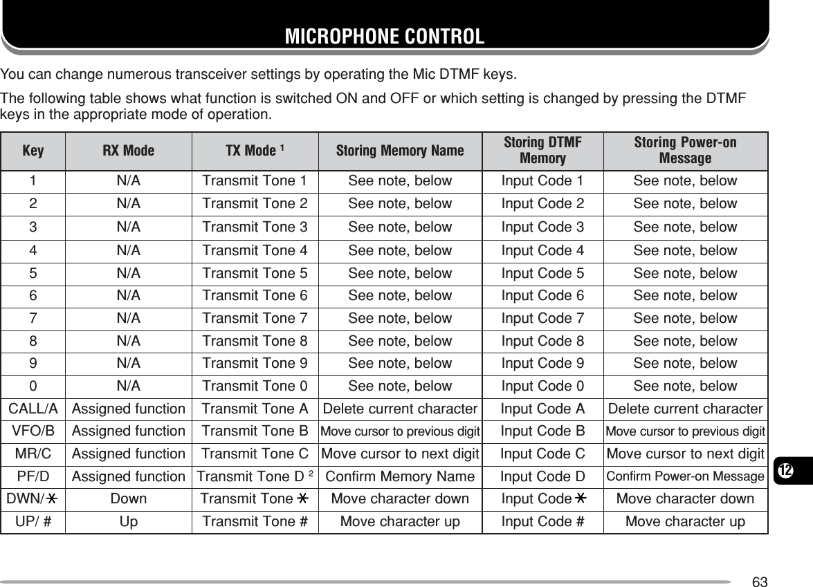
![64121DTMF tones are not transmitted in TX Mode if theDTMF Lock function is ON.2When transmitting a stored DTMF number, press Mic[PTT] + Mic [PF], release Mic [PF], then press aMemory Channel number from 0 to 9. To transmit the“D” tone, press Mic [PF] again.Note: When storing a Memory Name or Power-on message, theDTMF keys can be used. Each time a key is pressed, the displayedcharacter will change, according to the table below.yeK sretcarahCdeyalpsiD1QZ12ABC23DEF34GH I 45JKL56MNO67PRS78TUV89WX Y 90]ecaps[0—/MIC LOCKThe Mic Lock function disables the Mic PF keys toprevent you from accidentally changing the transceiveroperation.1Press [F], [MENU] and turn the Tuning control toselect Menu No. 34 (MC.L).2Press [MENU] and turn the Tuning control to select“ON” or “OFF” (default).3Press [MENU] to store the setting or any other key tocancel.4Press any key other than [MENU] to exit Menu Mode.Note: The Mic Lock function will not lock the DTMF keys.](https://usermanual.wiki/Kenwood-USA/31251110/User-Guide-360246-Page-70.png)
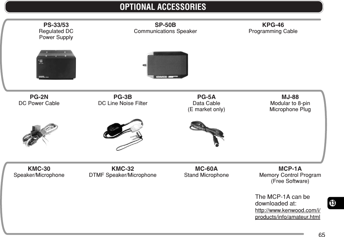
![6714Note:◆Record the date of purchase, serial number and dealer fromwhom this product was purchased.◆For your own information, retain a written record of anymaintenance performed on this product.◆When claiming warranty service, please include a photocopy ofthe bill of sale, or other proof-of-purchase showing the date ofsale.CLEANINGThe keys, controls, and case of the transceiver are likelyto become soiled after extended use. Remove thecontrols from the transceiver and clean them with aneutral detergent and warm water. Use a neutraldetergent (no strong chemicals) and a damp cloth toclean the case.RESETTING THE TRANSCEIVERIf your transceiver seems to be malfunctioning, resettingthe microprocessor may solve the problem. Thefollowing 2 reset modes are available. When performingthe reset, you may lose memory data and storedinformation. Back up or write down important databefore performing the reset.INITIAL SETTINGSThe factory defaults for the operating frequencies are asfollows.•Transceiver: 144.000 MHz•Weather Alert Channel (K market only): 162.550 MHzThe Memory Channels have no data stored. Refer topages 25 and 56 for the Call Channel and frequencystep size default values.Note: When in Channel Display Mode, you cannot perform VFOreset or Full reset.FULL RESETThis resets all transceiver parameters to the factorydefault values. There are two methods available forresetting the transceiver.Full Reset Method 1:1With the transceiver power OFF, press [F]+[ ](Power).•All indicators light momentarily, followed by the full resetconfirmation message.2Press [F].•“SURE ?” appears.3Press [F] again to reset the transceiver.•“WAIT” appears momentarily.](https://usermanual.wiki/Kenwood-USA/31251110/User-Guide-360246-Page-73.png)
![6814Full Reset Method 2:1Press [F], [MENU] and turn the Tuning control toselect Menu No. 99 (RESET).2Press [MENU] and turn the Tuning control to select“FULL”.3Press [MENU].•“SURE ?” appears.4Press [MENU] to reset the transceiver or any otherkey to cancel.•“WAIT” appears momentarily.VFO RESETThis resets the transceiver parameters excluding theDTMF Memory, the Memory channel contents, and theCall channel contents. There are two methods availablefor resetting the transceiver.Note: Menu No. 7 (P.VFO) and Menu No. 10 (OFFSET) return to thefactory default values.VFO Reset Method 1:1With the transceiver power OFF, press [VFO]+[ ](Power).•The VFO reset confirmation message appears.2Press [VFO].•“SURE ?” appears.3Press [VFO] again to reset the transceiver.•“WAIT” appears momentarily.VFO Reset Method 2:1Press [F], [MENU] and turn the Tuning control toselect Menu No. 99 (RESET).2Press [MENU] and turn the Tuning control to select“VFO”.3Press [MENU].•“SURE ?” appears.4Press [MENU] to reset the transceiver or any otherkey to cancel.](https://usermanual.wiki/Kenwood-USA/31251110/User-Guide-360246-Page-74.png)
![6914TROUBLESHOOTINGThe problems described in the following tables are commonly encountered operational malfunctions. These types ofdifficulties are usually caused by improper hook-up, accidental incorrect control settings, or operator error due toincomplete programming. These problems are usually not caused by circuit failure. Please review these tables and theappropriate section(s) of this instruction manual before assuming your transceiver is defective.melborP esuaCelbaborP noitcAevitcerroC .feRegaPtonlliwreviecsnartehTgnitcennocretfapurewopylppusrewopCDV8.31aehtgnisserpdna ][)rewoP(gnihtoN.hctiws.yalpsidehtnosraeppa1sawelbacrewopehT.sdrawkcabdetcennoc1elbacrewopCDdeilppusehttcennoC:yltcerrocdeR →kcalB;)+( →.)–(32rewopehtfoeromroenO.nepoerasesufelbac2.)s(esufnwolbehtfoesuacehtrofkooLynagnitcerrocdnagnitcepsniretfAehthtiw)s(esufwenallatsni,smelborp.sgnitaremas5,midootsiyalpsidehTdetcelesuoyhguohtneve.levelssenthgirbhgiha.wolootsiegatlovylppusehTsitnemeriuqeregatlovylppusehTCDV8.31 ±.)CDV8.51otV7.11(%51,egnarsihtedistuosiegatlovtupniehtfIro/dnaylppusrewopdetalugerruoytsujda.snoitcennocelbacrewopllakcehc4,3ebtonnacycneuqerfehTehtgninrutybdetcelesgninuT ybrolortnocciMgnisserp ]PU[ /]NWD[ ..detcelessawllaceRyromeMsserP ]OFV[ .51,03ehtdnasyek/snottubtsoMgninuT tonodlortnoc.noitcnuf.NOsisnoitcnufkcoLehtfoenO.snoitcnufkcoLehtfollakcolnU,85,3546](https://usermanual.wiki/Kenwood-USA/31251110/User-Guide-360246-Page-75.png)
![7014melborP esuaCelbaborP noitcAevitcerroC .feRegaPtonnacslennahCyromeMehtgninrutybdetcelesebgninuT ybrolortnocciMgnisserp ]PU[ /]NWD[ .ynaniderotsneebsahatadoN.slennahCyromeM.slennahCyromeMemosniataderotS92nevetimsnarttonnacuoYciMsserpuoyhguoht]TTP[ .1tonsawgulpenohporcimehTehtotniyletelpmocdetresni.rotcennoclenaptnorf1ehttresnineht,rewopehtFFOhctiwSbatgnikcolehtlitnugulpenohporcim.ecalpniskcilc62tesffotimsnartadetcelesuoYtimsnartehtsecalptahtehtedistuoycneuqerfycneuqerftimsnartelbawolla.egnar2sserP ]F[ ,]UNEM[ ehtnrutdna gninuT.)TFS(5.oNuneMtcelesotlortnocsserP ]UNEM[ ehtnrutdna gninuTsserP.”FFO“tcelesotlortnoc ]UNEM[yekynasserpneht,gnittesehterotsotnahtrehto ]UNEM[ .edoMuneMtixeot323siCNTlanretxeehT.gnittimsnart3ciMsserP ]TTP[ sahCNTehtretfa.gnittimsnartdehsinif—](https://usermanual.wiki/Kenwood-USA/31251110/User-Guide-360246-Page-76.png)