Kenwood USA 32253110 VHF Handheld Transceiver User Manual TK 2140K
Kenwood USA Corporation VHF Handheld Transceiver TK 2140K
Instruction Manual

© B62-XXXX-00 (K)
09 08 07 06 05 04 03 02 01 00
KENWOOD CORPORATION
INSTRUCTION MANUAL
VHF FM TRANSCEIVER
TK-2140
TK-3140
UHF FM TRANSCEIVER

i
WARNING:
EXPLOSIVE ATMOSPHERES (GASES, DUST, FUMES, etc.)
Turn off your transceiver while taking on fuel, or while parked in
gasoline service stations.
◆
GOVERNMENT LAW PROHIBITS THE OPERATION OF
UNLICENSED RADIO TRANSMITTERS WITHIN THE
TERRITORIES UNDER GOVERNMENT CONTROL.
◆
ILLEGAL OPERATION IS PUNISHABLE BY FINE OR
IMPRISONMENT OR BOTH.
◆
REFER SERVICE TO QUALIFIED TECHNICIANS ONLY.
SAFETY: It is important that the operator is aware of
and understands hazards common to the operation of
any transceiver.
THANK YOU
We are grateful you chose KENWOOD for your land
mobile radio applications. We believe this easy-to-use
transceiver will provide dependable communications to
keep personnel operating at peak efficiency.
KENWOOD transceivers incorporate the latest in
advanced technology. As a result, we feel strongly that
you will be pleased with the quality and features of this
product.
MODELS COVERED BY THIS MANUAL
• TK-2140: VHF FM Transceiver
• TK-3140: UHF FM Transceiver
NOTICES TO THE USER

ii
One or more of the following statements may be
applicable:
ATTENTION (U.S.A. Only):
The RBRC Recycle seal found on KENWOOD
nickel-cadmium (Ni-Cd) battery packs indicates
KENWOOD’s voluntary participation in an industry
program to collect and recycle Ni-Cd batteries after
their operating life has expired. The RBRC program
is an alternative to disposing Ni-Cd batteries with
your regular refuse or in municipal waste streams,
which is illegal in some areas.
For information on Ni-Cd battery recycling in your area, call (toll free)
1-800-8-BATTERY (1-800-822-8837).
KENWOOD’s involvement in this program is part of our commitment
to preserve our environment and conserve our natural resources.
FCC WARNING
This equipment generates or uses radio frequency energy. Changes
or modifications to this equipment may cause harmful interference
unless the modifications are expressly approved in the instruction
manual. The user could lose the authority to operate this equipment
if an unauthorized change or modification is made.
INFORMATION TO THE DIGITAL DEVICE USER REQUIRED BY
THE FCC
This equipment has been tested and found to comply with the limits
for a Class B digital device, pursuant to Part 15 of the FCC Rules.
These limits are designed to provide reasonable protection against
harmful interference in a residential installation.
This equipment generates, uses and can generate radio frequency
energy and, if not installed and used in accordance with the
instructions, may cause harmful interference to radio communications.
However, there is no guarantee that the interference will not occur in a
particular installation. If this equipment does cause harmful
interference to radio or television reception, which can be determined
by turning the equipment off and on, the user is encouraged to try to
correct the interference by one or more of the following measures:
•
Reorient or relocate the receiving antenna.
•
Increase the separation between the equipment and receiver.
•
Connect the equipment to an outlet on a circuit different from that
to which the receiver is connected.
•
Consult the dealer for technical assistance.

iii
CONTENTS
UNPACKING AND CHECKING EQUIPMENT................... 1
Supplied Accessories...................................... 1
PREPARATION .................................................. 2
Installing/ Removing the (Optional) Li-ion Battery Pack .. 2
Installing the (Optional) Antenna ........................ 3
Installing the Belt Clip..................................... 3
Installing the Cover over the Universal Connector ..... 4
Installing the (Optional KMC-25) Speaker/ Microphone... 4
GETTING ACQUAINTED ........................................ 5
Display ...................................................... 7
PROGRAMMABLE AUXILIARY FUNCTIONS ................. 8
OPERATION OVERVIEW.......................................10
Trunking Format...........................................10
Conventional Format .....................................10
OPERATING BASICS...........................................11
Switching Power ON/ OFF................................11
Adjusting the Volume.....................................11
Selecting a System/ Group/ Channel ...................11
Time-out Timer (TOT) ....................................12
TRUNKED OPERATION (Trunking Format) ..................13
Placing a Dispatch Call ..................................13
Receiving a Dispatch Call................................13
CONVENTIONAL OPERATION (Trunking Format)...........14
Transmitting ...............................................14
Receiving ..................................................14

iv
SYSTEM SCAN (Trunking Format) ...........................15
Scanning Trunked Systems ..............................15
Scanning Conventional Systems ........................15
Scan Lockout ..............................................16
Scan Revert................................................16
GROUP SCAN (Trunking Format) ............................17
CONVENTIONAL OPERATION (Conventional Format) .....18
Transmitting ...............................................18
Receiving ..................................................18
SCAN (Conventional Format) ................................19
Priority Scan...............................................19
2-TONE SIGNALLING (Conventional Format) ..............20
FleetSync™: ALPHANUMERIC 2-WAY PAGING FUNCTION ... 21
Key Functions .............................................21
Selcall (Selective Calling) ...............................22
Status Message ...........................................23
Optional Short Messages Feature ......................26
AUDIBLE USER FEEDBACK TONES ..........................27

1
UNPACKING AND CHECKING EQUIPMENT
Note: The following unpacking instructions are for use by your
KENWOOD dealer, an authorized KENWOOD service facility, or the
factory.
Carefully unpack the transceiver. We recommend that
you identify the items listed in the following table before
discarding the packing material. If any items are
missing or have been damaged during shipment, file a
claim with the carrier immediately.
■Supplied Accessories
metI rebmuNtraP ytitnauQ
pilctleB1
pacrotcennoclarevinU1
teswercS1
dracytnarraW1
launamnoitcurtsnI1
Belt clip Universal
connector cap Screw set

2
PREPARATION
Match the guides of the
battery pack with the
corresponding grooves on
the upper rear of the
transceiver, then firmly
press the battery pack to
lock it in place.
To remove the battery pack,
press the release latch and
pull the battery pack away
from the transceiver.
■Installing/ Removing the (Optional) Li-ion Battery Pack
CAUTION:
◆
DO NOT RECHARGE THE BATTERY PACK IF IT IS ALREADY
FULLY CHARGED. DOING SO MAY CAUSE THE LIFE OF
THE BATTERY PACK TO SHORTEN OR THE BATTERY PACK
MAY BE DAMAGED.
◆
AFTER RECHARGING THE BATTERY PACK, DISCONNECT
IT FROM THE CHARGER. IF THE CHARGER POWER IS
RESET (TURNED ON AFTER BEING TURNED OFF),
RECHARGING WILL START AGAIN AND THE BATTERY PACK
WILL BECOME OVERCHARGED.
◆
DO NOT SHORT THE BATTERY TERMINALS OR DISPOSE
OF THE BATTERY BY FIRE.
◆
NEVER ATTEMPT TO REMOVE THE CASING FROM THE
BATTERY PACK.

3
Screw the antenna into the
connector on the top of the
transceiver by holding the
antenna at its base and
turning it clockwise until
secure.
■Installing the Belt Clip
If necessary, attach the belt
clip using the two supplied
3 x 6 mm screws.
Note: If the belt clip is not installed,
its mounting location may get hot
during continuous transmission or
when left sitting in a hot
environment.
■Installing the (Optional) Antenna

4
If you are not using the
optional KMC-25 speaker/
microphone, install the
cover over the univeral
connector using the
supplied 4 x 6 mm screw.
■Installing the Cover over the Universal Connector
■Installing the (Optional KMC-25) Speaker/ Microphone
1Insert the guide of the speaker/ microphone
connector into the groove of the universal
connector.
2Secure the connector in place using the attached
screw.

5
GETTING ACQUAINTED
qq
qq
qAntenna connector
Connect an (optional) antenna here.
ww
ww
wRotary encoder
Rotate this encoder to activate its programmable
function. (System or Group Up/ Down in Trunking
Format, and Group or Channel Up/ Down in
Conventional Format.) For further details, contact
your dealer.

6
ee
ee
ePOWER switch/ VOLUME control
Turn clockwise to switch ON the transceiver. Rotate
to adjust the volume. Turn counterclockwise fully to
switch OFF the transceiver.
rr
rr
rTransmit/ Battery low indicator
This red LED lights during transmission. If
programmed by your dealer, when the battery pack
power is low, the LED flashes during transmission.
Replace or recharge the battery pack.
tt
tt
tAuxiliary (orange) key
Press to activate its auxiliary function {page 8}.
yy
yy
yBattery pack release latch
Press this latch to release the battery pack. See
“Installing/ Removing the (Optional) Li-ion Battery
Pack” on page 2.
uu
uu
uPTT (Push-To-Talk) switch
Press this switch, then speak into the microphone to
call a station.
ii
ii
iSide 1, Side 2 keys
Press to activate their auxiliary functions {page 8}.
oo
oo
oS, A, tt
tt
tB, and Css
ss
s keys
Press to activate their auxiliary functions {page 8}.
!0!0
!0!0
!0 Universal connector
Connect the (optional KMC-25) speaker/ microphone
here. Otherwise, keep the supplied cover in place.
7
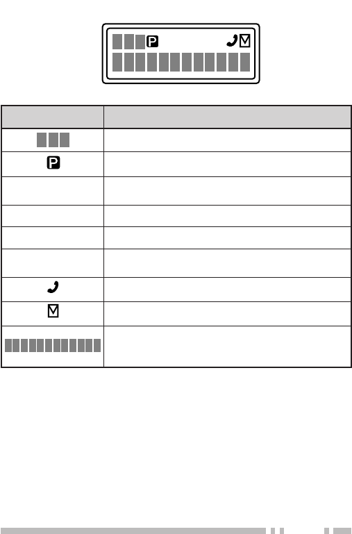
■Display
SVC
MON SCN LO
rotacidnI noitpircseD
.srebmunpuorgdnalennahcehtsyalpsiD
.nacSytiroirPgnimrofrepnehwsraeppA
sademmargorpyekehtnehwsraeppA rotinoM si
.desserp
.reviecsnartsihtnodesutonsinocisihT
.nacSgnimrofrepnehwsraeppA
sademmargorpyekehtnehwsraeppA rewoPFR
OL .desserpsi
.metsysenohpeletehtgnisuelihwsraeppA
.egassemaevahuoynehwsraeppA
puorg/metsysehtroemanpuorgehtsyalpsiD stigid2gniniamerehT.stigid01otpuhtiwrebmun .srotacidnisuoiravrofdesuera
MON
SVC
SCN
LO

8
PROGRAMMABLE AUXILIARY FUNCTIONS
Keys t, i and o {pages 5 and 6} can be programmed
with the auxiliary functions listed in the following table.
The keys can only be programmed with functions,
depending on whether you are using Conventional
Format or Trunking Format. Please contact your dealer
for further details on these functions.
noitcnuF lanoitnevnoC tamroF gniknurT tamroF
leTotuAoNseY
nwoDlennahCseYoN
pUlennahCseYoN
nwoD/pUlennahCseYoN
)TOB(DIFMTDseYseY
)TOE(DIFMTDseYseY
retcarahCyalpsiDseYseY
ycnegremE
1
seYseY
nwoDpuorGseYseY
pUpuorGseYseY
nwoD/pUpuorGseYseY
lennahCemoHseYoN
puorGemoHoNseY
kcoLyeKseYseY
pmaLseYseY
)OTS/LCR(yromeMseYseY
)LCR(yromeMseYseY
)OTS(yromeMseYseY
edoMegaseMseYseY

9
noitcnuF lanoitnevnoC tamroF gniknurT tamroF
rotinoM(ArotinoM ))yratnemoM(etumnU seYseY
rotinoM(BrotinoM ))elggoT(etumnU seYseY
reirraC(CrotinoM ))yratnemoM(hcleuqS seYseY
reirraC(DrotinoM ))elggoT(hcleuqS seYseY
TSOseYoN
laideRseYseY
OLrewoPFRseYseY
nacSseYseY
ddA/leDnacSseYseY
leD/pmeTnacSoNseY
noitaunettAPSseYseY
leveLQSseYoN
nwoDmetsySoNseY
pUmetsySoNseY
nwoD/pUmetsySoNseY
dnuorAklaTseYoN
tcennocsiDleToNseY
1This function can be programmed only on key t, the
Auxiliary (orange) key.

10
OPERATION OVERVIEW
Your dealer can program your transceiver for either
Trunking Format or Conventional Format.
■Trunking Format
This format can handle up to 32 systems with up to
250 groups in each system. The transceiver can be
used in both trunked mode and conventional mode.
Systems, groups, and their functions are
programmed by your dealer.
■Conventional Format
This format can handle up to 250 groups with 250
channels in each group. The transceiver can be
used only in conventional mode. Groups, channels,
and their functions are programmed by your dealer.

11
OPERATING BASICS
■Switching Power ON/ OFF
Turn the Power switch/ Volume control clockwise to
switch the transceiver ON.
Turn the Power switch/ Volume control
counterclockwise to switch the transceiver OFF.
If the Radio Password function is programmed,
“PASSWORD” will appear on the display when the
power is turned ON. To unlock the transceiver, enter
the password, then press the S key. If you enter the
wrong password, an error tone sounds and the
transceiver remains locked. The password can
contain a maximum of 6 digits.
■Adjusting the Volume
Rotate the Power switch/ Volume control to adjust
the volume. Clockwise increases the volume and
counterclockwise decreases it.
■Selecting a System/ Group/ Channel
Select the desired system and group (Trunking
Format) using the encoder and the keys programmed
with System or Group Up/ Down.
Select the desired group and channel (Conventional
Format) using the encoder and the keys programmed
with Group or Channel Up/ Down.

12
■Time-out Timer (TOT)
The purpose of the Time-out Timer is to prevent any
caller from using a channel for an extended period of
time.
If you continuously transmit for a period of time that
exceeds the programmed time, the transceiver will
stop transmitting and an alert tone will sound. To
stop the tone, release the PTT switch.
Your dealer can program the TOT time in the range
of 15 seconds to 10 minutes.

13
TRUNKED OPERATION (Trunking Format)
■Placing a Dispatch Call
1Select the desired system and group using the
encoder and the System or Group keys.
2Press the PTT switch.
3If a tone does not sound, communication is
possible; start speaking into the microphone.
Release the PTT switch to receive.
•For best sound quality at the receiving station, hold
the microphone approximately 1.5 inches
(3 ~ 4 cm) from your mouth.
■Receiving a Dispatch Call
1Select the desired system and group using the
encoder and the System or Group keys. (If the
Scan function has been programmed, you can
switch it ON or OFF as desired.)
2When you hear the dispatcher’s voice, readjust
the volume as necessary.

14
CONVENTIONAL OPERATION (Trunking Format)
■Transmitting
1Select the desired system and group using the
encoder and the System or Group keys.
2Press the key programmed as Monitor to check
whether or not the channel is free.
•If the channel is busy, wait until it becomes free.
3Press the PTT switch and speak into the
microphone. Release the PTT switch to receive.
•For best sound quality at the receiving station, hold
the microphone approximately 1.5 inches
(3 ~ 4 cm) from your mouth.
■Receiving
1Select the desired system and group using the
encoder and the System or Group keys. (If the
Scan function has been programmed, you can
switch it ON or OFF as desired.)
2When you hear the dispatcher’s voice, readjust
the volume as necessary.

15
SYSTEM SCAN (Trunking Format)
If the Scan function is programmed, systems can be
scanned by pressing the key programmed as Scan.
When the Scan key is pressed, the SCN indicator and
“-SCAN-” or the revert system/ group number, appear on
the display and scanning starts. The systems not locked
out of the scanning sequence are scanned.
When a call is received, scanning stops and the system
and group digits appear. Press the PTT switch and
speak into the microphone to respond to the call. The
transceiver will continue scanning after a predetermined
time delay if the PTT switch is released and no further
signal is received.
■Scanning Trunked Systems
When scanning trunked systems, the revert groups
and the groups not locked out of the scanning
sequence are scanned. See “GROUP SCAN” on
page 17.
■Scanning Conventional Systems
When scanning conventional systems, the revert
groups and the groups not locked out of the scanning
sequence are scanned. See “GROUP SCAN” on
page 17.

16
■Scan Lockout
If a programmable auxiliary key is programmed with
Scan Del/Add, each system can be locked out of the
scan sequence manually. The delete indicator ( s )
will appear on the display when the selected system
is locked out.
■Scan Revert
You can select revert systems and groups using the
encoder and the System or Group keys.
Three types of Scan Reverts which can be
programmed by your dealer are available:
•Last Called Revert: The last system/ group
received is assigned as the new revert system
and group.
•Last Used Revert: The last system/ group
responded to is assigned as the new revert
system and group.
•Selected: The last system/ group selected is
assigned as the new revert system and group.

17
GROUP SCAN (Trunking Format)
Group Scan is available for both trunked and
conventional systems. This feature is useful when more
than one group is programmed in a system. Group
Scan is set by your dealer on request. It scans the
revert groups as well as groups that are allowed to be
scanned.
When a call is received, the group indicator shows the
group number, and that group becomes the revert
group. Simply press the PTT switch to respond to the
call.
You can also perform Group Scan while using a priority
channel. Please contact your dealer for information
concerning Priority Scan.

18
CONVENTIONAL OPERATION (Conventional Format)
■Transmitting
1Select the desired group and channel using the
encoder and the Group or Channel keys.
2Press the key programmed as Monitor to check
whether or not the channel is free.
•If the channel is busy, wait until it becomes free.
3Press the PTT switch and speak into the
microphone. Release the PTT switch to receive.
•For best sound quality at the receiving station, hold
the microphone approximately 1.5 inches
(3 ~ 4 cm) from your mouth.
■Receiving
1Select the desired group and channel using the
encoder and the Group or Channel keys. (If the
Scan function has been programmed, you can
switch it ON or OFF as desired.)
2When you hear a caller’s voice, readjust the
volume as necessary.

19
SCAN (Conventional Format)
If the Scan function is programmed, groups or channels
can be scanned by pressing the key programmed as
Scan. Scan can be used as either Single Scan or Multi
Scan. Single Scan monitors only the channels of a
single group. Multi Scan monitors all channels of every
group. When the Scan key is pressed, the SCN
indicator and “-SCAN-” or the revert group/ channel
number, appear on the display and scanning starts.
When a call is received, scanning stops and the group
and channel digits appear. Press the PTT switch and
speak into the microphone to respond to the call. The
transceiver will continue scanning after an adjustable
time delay, if the PTT switch is released, and no further
signal is received.
When the displayed group is not locked out of the
scanning sequence, the add indicator ( ) will appear on
the display.
■Priority Scan
The priority channel must be programmed in order
for Priority Scan to function.
The transceiver will automatically change to the
priority channel when a signal is received on it, even
if a signal is being received on a normal channel.
The indicator appears when the displayed channel
is the priority channel.

20
2-TONE SIGNALLING (Conventional Format)
2-Tone Signalling is either activated or deactivated by
your dealer.
2-Tone Signalling only opens the squelch when the
transceiver receives two tones corresponding to those
set up in the transceiver. When the squelch opens, you
will be able to hear the caller without any further action.
After a correct 2-Tone signal is received and the squelch
opens, pressing the key programmed as Monitor will
cancel the connection.
If your dealer programmed Transpond for 2-Tone
Signalling, your transceiver will automatically send an
acknowledgment signal to the station that called you
with the correct 2-Tone signal. Transpond does not
function when you are called as a Group call.
If your dealer programmed Tone Alert for 2-Tone
Signalling, your transceiver will emit a beep when the
correct 2-Tone signal is received.
Note: This transceiver is only capable of decoding 2-Tone Signals. It
cannot encode a 2-Tone Signal.
21
FleetSync™ is an Alphanumeric 2-way Paging Function,
and is a protocol owned by KENWOOD Corporation.
FleetSync™ enables a variety of paging functions on your
transceiver, some of which depend on dealer programming.
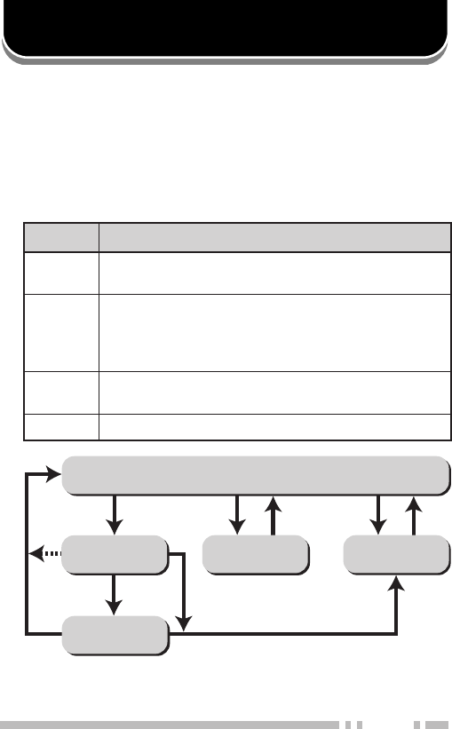
■Key Functions
FleetSync™: ALPHANUMERIC 2-WAY PAGING FUNCTION
Selcall Mode
1
Status Mode
Stack Mode
New Message
Display Mode
Normal Operating Mode
Press A
or receive
a Selcall
Receive
a new
message
Hold A for
1 second
Press
any key Press
A or #
Press
A or #
Press
A or #
Hold A or # for 1 second
yeK noitcnuF
AninwohssaedomreviecsnartehtegnahcotsserP .wolebmargaideht
S
ehtneewtebelggototedoMkcatSnielihwsserP dnasserP.DIs’rellacehtdnaegassemdeviecer ehteteledotdnoces1nahteromrofdloh .egassemdeyalpsid
tt
t
ttB,Css
s
ss .segassemdeviecergnillorcs-otuapotsotsserP .yllaunamllorcsotsserposlA
TTP .llacaetaitiniotsserP
1Depending on how your dealer programmed the transceiver,
Selcall Mode may be skipped or the transceiver may exit Selcall
Mode automatically (as shown by the dash arrow).

22
■Selcall (Selective Calling)
A Selcall is a voice call to a particular station or to a
group of stations.
To Transmit:
1Select your desired system and group (or group
and channel).
2Press the A key to enter Selcall Mode.
3Use the encoder to select the ID of the station
you want to call.
4Press the PTT switch and begin your
conversation.
To Receive:
An alert tone will sound, the transceiver will
automatically enter Selcall Mode, and the calling
station’s ID will appear when a Selcall is received.
To respond to the call, press the PTT switch and
speak into the microphone.
Identification Codes:
An ID code is a combination of a 3-digit Fleet
number and a 4-digit ID number. Each transceiver
must have its own Fleet and ID number.
•Enter a Fleet number (100 ~ 349) to make a group call.

23
•Enter an ID number (1000 ~ 4999) to make an
individual call in your fleet.
•Enter a Fleet number followed by an ID number to
make an individual call in your desired fleet
(Inter-fleet call).
•Select “ALL” Fleet and “ALL” ID to make a call to all
units (Broadcast call).
•Select “ALL” Fleet and enter an ID number to make a
call to the selected ID in all fleets (Supervisor call).
Note:
◆
Broadcast and Supervisor calls are programmed functions that
cannot be made with a keypad.
◆
The ID range may be limited by programming.
■Status Message
You can send and receive 2-digit Status messages
(10 ~ 79) which may be decided in your talk group.
Messages can contain up to 16 alphanumeric
characters.
A maximum of 9 received messages can be stored in
the stack memory of your transceiver. These saved
messages can be reviewed after reception. If the
stack memory is full, the oldest message will be
erased when a new message is received. The mail
icon ( ) lights when a message is stored in the
stack memory.
Note: All stored messages will be cleared when the transceiver
power is turned OFF.

24
To Transmit:
1Select your desired system and group (or group
and channel).
2Press the A key to enter Selcall Mode.
3Use the encoder to select the ID of the station
you want to call.
4Press the A key to enter Status Mode.
5Use the encoder to select the status you want to
transmit.
6Press the PTT switch to initiate the Status call.
•“COMPLETE” is displayed when the call has been
successfully transmitted.
To Receive:
The mail icon ( ) will flash and a calling ID or text
message will appear when a Status call is received.
•The display alternates between the caller ID and the
message.
Press any key to return to Normal Operation Mode.

25
To Review the Messages in the Stack Memory:
1Press and hold the A key for more than 1 second
to enter Stack Mode.
•The last received message is displayed with the
message number. “S” (Status) appears with the
number.
2Use the encoder to select the message you want
to view (if more than one message is stored in the
stack memory).
3Press the tt
tt
tB key or Css
ss
s key to stop the
message from auto-scrolling if desired. Also use
these keys to scroll through the message
manually.
4Press the S key to toggle between the message
and the caller’s ID.
5To erase the message, press and hold the S key
for more than 1 second.
Automatic Status Response:
If you pre-select a status number and then leave the
transceier in Status Mode, the transceiver will
automatically respond with that status number when
a request from the base station is received. (The
base station request function is optional.)

26
■Optional Short Messages Feature
Received short messages (maximum of 48
characters) are displayed the same as Status
messages {page 23}, however only 4 short
messages can be stored in the stack memory. “M”
(Message) and the message number appear with the
message.

27
AUDIBLE USER FEEDBACK TONES
The transceiver emits various tones to indicate the
transceiver’s operating status. Contact your dealer for
further information on these tones.
enoT lanoitnevnoC tamroF gniknurT tamroF
trelAseYseY
ysuBseYseY
nODBDseYseY
ffODBDseYseY
yaleDoNseY
yneDoNseY
/edoMkcaBgniRmetsySeerF edoMhcraeSmetsyS oNseY
llaCpuorGseYseY
llaClaudividnIseYseY
tpecretnIoNseY
rorrEtupnIyeKseYseY
]A[sserPyeKseYseY
]B[sserPyeKseYseY
]C[sserPyeKseYseY
tnemeergAdrowssaPseYseY
NOrewoPseYseY
trelAerPseYoN
deecorPoNseY
esaeleRTTPseYseY
eueuQoNseY

28
enoT lanoitnevnoC tamroF gniknurT tamroF
gnigniRoNseY
revOlloRseYseY
hcraeSmetsySoNseY
dnEhcraeSmetsySoNseY
dnopsnarTseYseY