Kenwood USA 32263130 UHF Hand held to face User Manual TK 2140 3140 E 00 Cover
Kenwood USA Corporation UHF Hand held to face TK 2140 3140 E 00 Cover
UserManual.wiki
>
Kenwood USA
>
32263130 User Manual
Manual
Navigation menu
Upload a User Manual
Namespaces
Wiki Guide
HTML
PDF
Info
Views
User Manual
Discussion / Help
Navigation
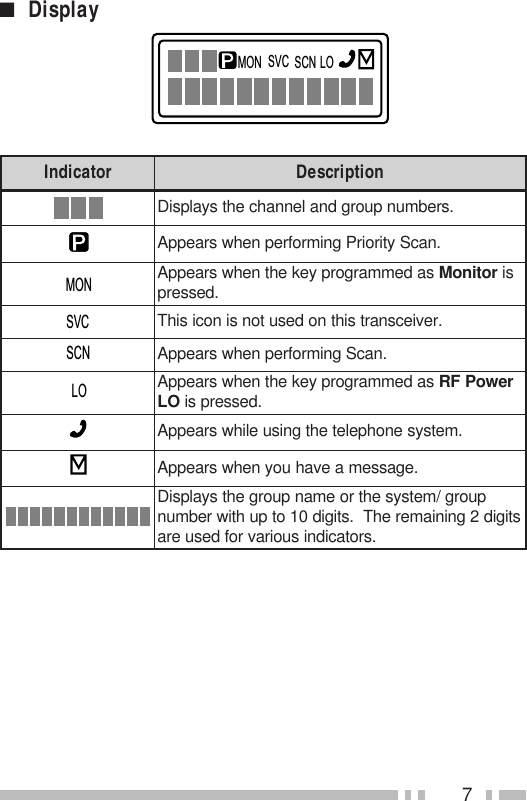
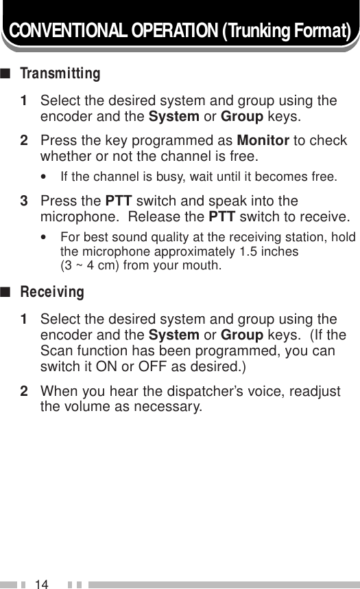
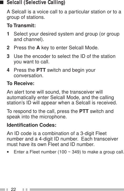
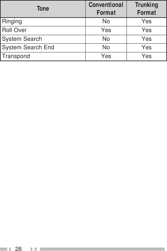
![27AUDIBLE USER FEEDBACK TONESThe transceiver emits various tones to indicate thetransceiver’s operating status. Contact your dealer forfurther information on these tones.enoT lanoitnevnoC tamroF gniknurT tamroFtrelAseYseYysuBseYseYnODBDseYseYffODBDseYseYyaleDoNseYyneDoNseY/edoMkcaBgniRmetsySeerF edoMhcraeSmetsyS oNseYllaCpuorGseYseYllaClaudividnIseYseYtpecretnIoNseYrorrEtupnIyeKseYseY]A[sserPyeKseYseY]B[sserPyeKseYseY]C[sserPyeKseYseYtnemeergAdrowssaPseYseYNOrewoPseYseYtrelAerPseYoNdeecorPoNseYesaeleRTTPseYseYeueuQoNseY](https://usermanual.wiki/Kenwood-USA/32263130/User-Guide-183676-Page-32.png)