Kenwood USA 33063110 800 MHz APCO P25 Transceiver User Manual PRODUCT SPECIFICATIONS
Kenwood USA Corporation 800 MHz APCO P25 Transceiver PRODUCT SPECIFICATIONS
Contents
- 1. Instruction Manual
- 2. Safety Information Statement
- 3. Mandatory Safety Instructions
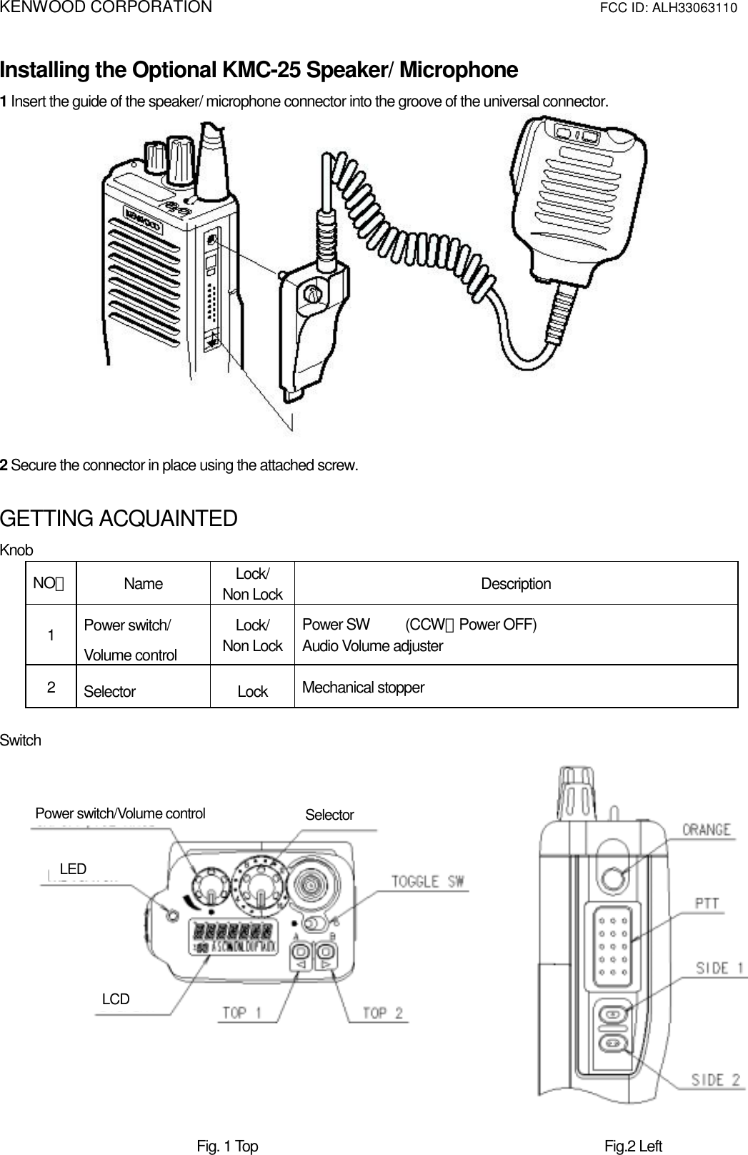
Instruction Manual