Kenwood USA 33063110 800 MHz APCO P25 Transceiver User Manual PRODUCT SPECIFICATIONS
Kenwood USA Corporation 800 MHz APCO P25 Transceiver PRODUCT SPECIFICATIONS
Contents
- 1. Instruction Manual
- 2. Safety Information Statement
- 3. Mandatory Safety Instructions
Instruction Manual
KENWOOD CORPORATION FCC ID: ALH33063110
INSTRUCTION MANUAL
TK-5400:
THANK YOU!
We are grateful you chose KENWOOD for your land mobile radio applications. We believe this easy-to-use transceiver
will provide dependable communications to keep personnel operating at peak efficiency.
KENWOOD transceivers incorporate the latest in advanced technology. As a result, we feel strongly that you will be
pleased with the quality and features of this product.
NOTICES TO THE USER
WARNING:
◆
◆◆
◆ GOVERNMENT LAW PROHIBITS THE OPERATION OF UNLICENSED RADIO TRANSMITTERS WITHIN THE
TERRITORIES UNDER GOVERNMENT CONTROL.
◆
◆◆
◆ ILLEGAL OPERATION IS PUNISHABLE BY FINE OR IMPRISONMENT OR BOTH.
◆
◆◆
◆ REFER SERVICE TO QUALIFIED TECHNICIANS ONLY.
◆
◆◆
◆ DO NOT OPERATE YOUR TRANSCEIVER IN EXPLOSIVE ATMOSPHERES (GASES, DUST, FUMES, ETC.).
◆
◆◆
◆ TURN OFF YOUR TRANSCEIVER WHILE TAKING ON FUEL, OR WHILE PARKED IN GASOLINE SERVICE
STATIONS.
SAFETY:
It is important that the operator is aware of and understands hazards common to the operation of any transceiver.
WARNING:
EXPLOSIVE ATMOSPHERES (GASES, DUST, FUMES, etc.)
Turn off your transceiver while taking on fuel, or while parked in gasoline service stations.
One or more of the following statements may be applicable:
FCC WARNING
This equipment generates or uses radio frequency energy. Changes or modifications to this equipment may cause
harmful interference unless the modifications are expressly approved in the instruction manual. The user could lose the
authority to operate this equipment if an unauthorized change or modification is made.
INFORMATION TO THE DIGITAL DEVICE USER REQUIRED BY THE FCC
This equipment has been tested and found to comply with the limits for a Class B digital device, pursuant to Part 15 of
the FCC Rules.
These limits are designed to provide reasonable protection against harmful interference in a residential installation.
This equipment generates, uses and can generate radio frequency energy and, if not installed and used in accordance
with the instructions, may cause harmful interference to radio communications.
However, there is no guarantee that the interference will not occur in a particular installation. If this equipment does
cause harmful interference to radio or television reception, which can be determined by turning the equipment off and on,
the user is encouraged to try to correct the interference by one or more of the following measures:
Reorient or relocate the receiving antenna.
Increase the separation between the equipment and receiver.
Connect the equipment to an outlet on a circuit different from that to which the receiver is connected.
Consult the dealer for technical assistance.
KENWOOD CORPORATION FCC ID: ALH33063110
ATTENTION (U.S.A. Only):
The RBRC Recycle seal found on KENWOOD nickel-cadmium (Ni-Cd) battery packs
indicates KENWOOD’s voluntary participation in an industry program to collect and
recycle Ni-Cd batteries after their operating life has expired. The RBRC program is an
alternative to disposing Ni-Cd batteries with your regular refuse or in municipal waste
streams, which is illegal in some areas.
For information on Ni-Cd battery recycling in your area, call (toll free)
1-800-8-BATTERY (1-800-822-8837). KENWOOD’s involvement in this program is
part of our commitment to preserve our environment and conserve our natural
resources.
UNPACKING AND CHECKING EQUIPMENT
Note:
The following unpacking instructions are for use by your
KENWOOD dealer, an authorized KENWOOD service facility, or the factory.
Carefully unpack the transceiver. We recommend that you identify the items listed in the following table before
discarding the packing material. If any items are missing or have been damaged during shipment, file a claim with the
carrier immediately.
◆
◆◆
◆ Accessories
Quantity
Item Part Number K K2
Instruction Manual B62 – 1606 - *0 1 1
Warranty Card B46 - 0470 -*0 1 1
Belt Hook J29 – 0652 - *5 1 1
Screw Set N99 - 2004 - *5 1 1
Dressing Plate B03 – 0594 - *4 1 1
Cap B09 - 0363 - *3 1 1
Stopper D32 – 0421 - *4 1 1
KENWOOD CORPORATION FCC ID: ALH33063110
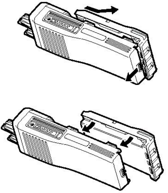
Installing/ Removing the Optional Battery Pack PREPARATION
The battery pack is not charged at the factory; charge it before use.
CAUTION:
◆
◆◆
◆ DO NOT RECHARGE THE BATTERY PACK IF IT IS ALREADY FULLY CHARGED. DOING SO MAY CAUSE
THE LIFE OF THE BATTERY PACK TO SHORTEN OR THE BATTERY PACK MAY BE DAMAGED.
◆
◆◆
◆ AFTER RECHARGING THE BATTERY PACK, DISCONNECT IT FROM THE CHARGER. IF THE CHARGER
POWER IS RESET (TURNED ON AFTER BEING TURNED OFF), RECHARGING WILL START AGAIN AND THE
BATTERY PACK WILL BECOME OVERCHARGED.
◆
◆◆
◆ DO NOT SHORT THE BATTERY TERMINALS OR DISPOSE OF THE BATTERY BY FIRE.
◆
◆◆
◆ NEVER ATTEMPT TO REMOVE THE CASING FROM THE BATTERY PACK.
1 Match the four grooves of the battery pack with the corresponding guides on the back of the transceiver.
2 Slide the battery pack along the back of the transceiver until the release latch on the base of the transceiver locks.
3 To remove the battery pack, pull back on the release latch and slide the pack away from the transceiver.
KENWOOD CORPORATION FCC ID: ALH33063110
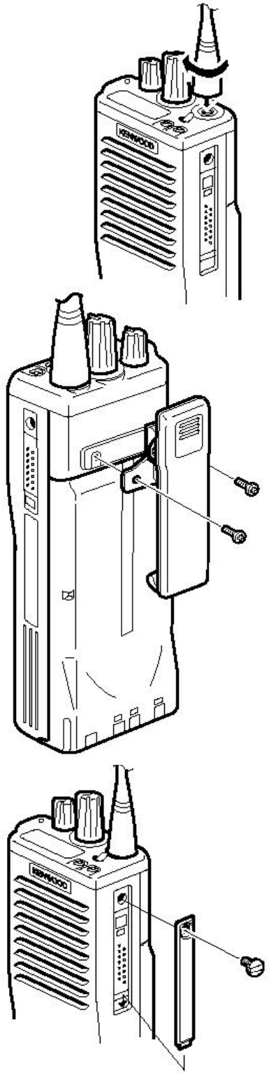
Installing the Antenna
Screw the antenna into the connector on the top of the transceiver by holding the
antenna at its base and turning it clockwise until secure.
Installing the Belt Clip
If necessary, attach the belt clip using the two supplied 3 x 6 mm
screws.
Note:
If the belt clip is not installed, its mounting location may get hot
during continuous transmission or when left sitting in a hot
environment.
Installing the Cap over the Universal
Connector
If you are not using the optional KMC-25 speaker/ microphone, install
the cap over the universal connector using the supplied 4 x 6 mm
screw.
Note:
To keep the transceiver water resistant, you must cover the universal
connector with the cap or the speaker/ microphone connector.
KENWOOD CORPORATION FCC ID: ALH33063110
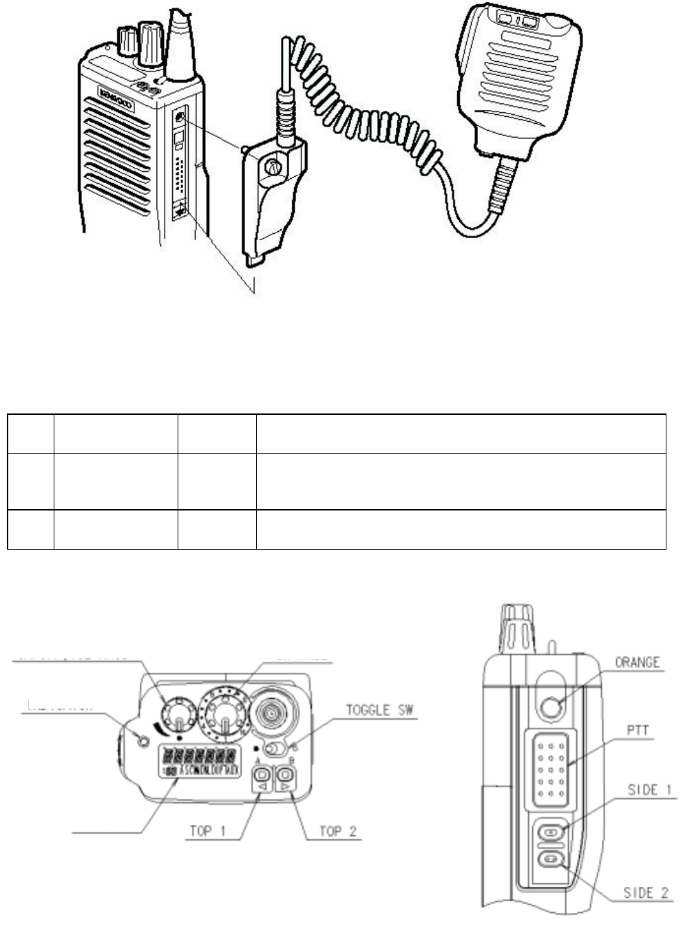
Installing the Optional KMC-25 Speaker/ Microphone
1 Insert the guide of the speaker/ microphone connector into the groove of the universal connector.
2 Secure the connector in place using the attached screw.
GETTING ACQUAINTED
Knob
NO. Name Lock/
Non Lock Description
1 Power switch/
Volume control
Lock/
Non Lock
Power SW (CCW:Power OFF)
Audio Volume adjuster
2 Selector Lock
Mechanical stopper
Switch
Fig. 1 Top Fig.2 Left
LCD
LED
Power switch/Volume control Selector

KENWOOD CORPORATION FCC ID: ALH33063110
<Top >
NO. Name Lock/
Non Lock Description
1 Toggle SW Lock Programmable default:No Function
2 Top 1 Non Lock Programmable default:No Function
3 Top 2 Non Lock Programmable default:No Function
<Left side>
NO. Name Lock/
Non Lock Description
1 PTT Non Lock
TX ON/OFF
2 Side 1 Non Lock Programmable default:No Function
3 Side 2 Non Lock Programmable default:No Function
4 Orange Non Lock
Programmable default:No Function
<Front>
NO. Name Lock/
No Lock Description
1 12 Key Pad
Non Lock To select code of DTMF encode and operator selectable tone.
Only K2 destination.
DISPLAY
LED
NO. Name Description
1 LED
The LED is three colors.
Lights green while receiving at user mode.Light red while transmitting,
flashes red when the battery power is low while transmitting.Lights
orange when individual called.
KENWOOD CORPORATION FCC ID: ALH33063110
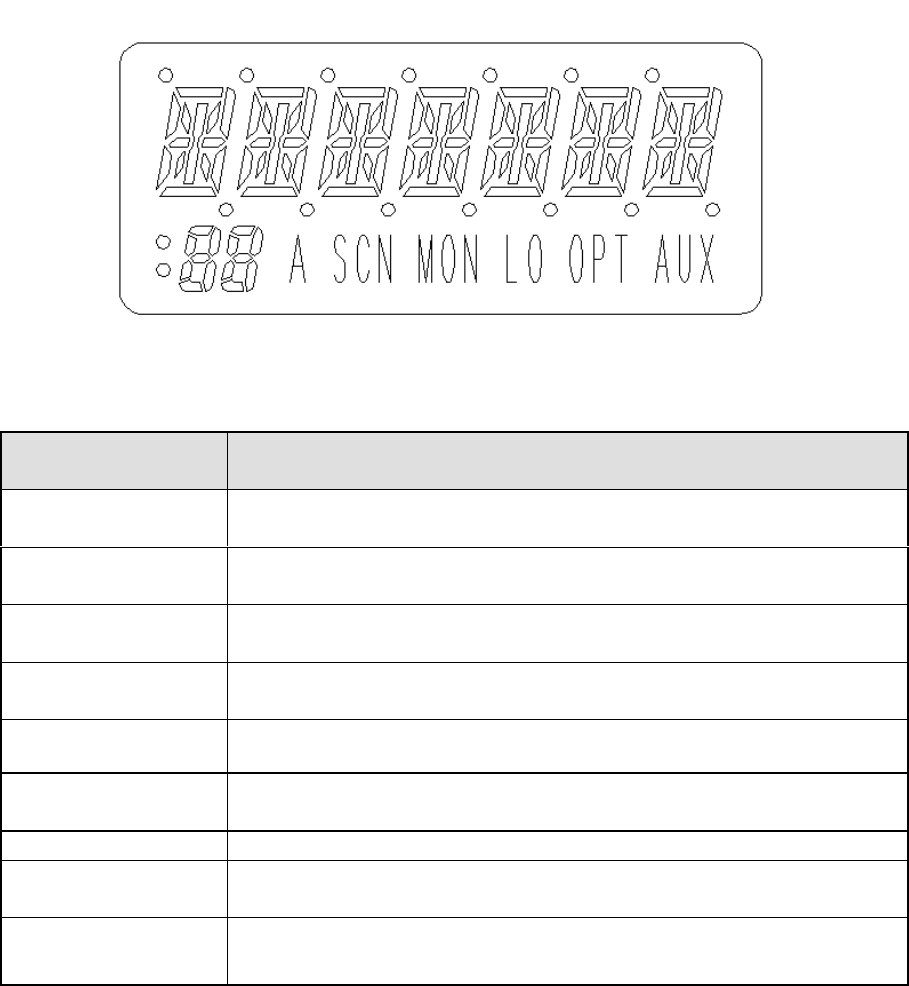
4.3.2 LCD
Fig. 3 LCD
Indicator Details
Alphanumeric display Displays the operating zone or channel number,or the zone or channel
name.Also displays various menu functions.
7 Segment display Displays the operating zone or channel number,or the zone or channel
name.Also displays various functions.
: The upper dot indicates,when the hundreds digit of channel number is 2.
The lower dot indicates,when the hundreds digit of channel number is 1.
A The channel of indicating become an object of scan,
the 「A」 display comes up.
SCN The 「SCN」 indicates when the radio is scanning.
MON
When the radio cancel signaling and use carrier squelch,
the 「MON」 display comes up.
LO Low power indicator.
OPT
When Operator Selectable Tone is to be ON,the 「OPT」 display
comes up.
AUX Encryption is to be ON,the 「AUX」 display comes up.

KENWOOD CORPORATION FCC ID: ALH33063110
TERMINAL
Universal connector
connector cover for blindfold mode of resin is possible.
NO. Name Description I/O
1 SSW EXT/INT SP switch input I
2 SP+ BTL output + for external speaker O
3 SP- BTL output − for external speaker O
4 MSW/CTS EXT/INT MIC switch input
Clear To Send
I
5 EMC External microphone input I
6 EME External microphone earth ―――
7 PTT PTT input I
8 REM Programmable function key input I
9 RTS Request To Send O
10 E Earth ―――
11 5M 5V output O
12 TXD Serial data output O
13 RXD Serial data input I
14 DSR Data Set Ready I
Battery Terminal
It’s type of spring plate. The minus terminal connect to chassis ground
It’s mounted rear side of radio and mounting instruction is slide method.
OTHER
Rear A rail and a hook for battery installation.
Space which affixes name plate.Model name plate
Screw hole for belt hook installation.
Bottom
Battery release lever
KENWOOD CORPORATION FCC ID: ALH33063110
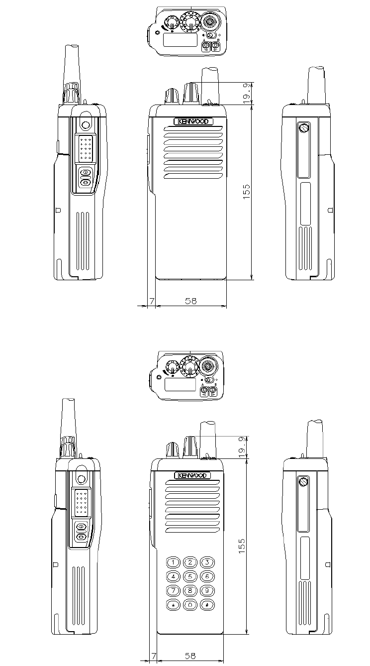
Appearance with 12key Pad (with KNB-17A)
Appearance
Appearance without 12key Pad (with KNB-17A)
KENWOOD CORPORATION FCC ID: ALH33063110
OPERATING BASICSATING BASICS
◆
◆◆
◆ Switching Power ON/OFF
Turn the Power switch/ Volume control clockwise to switch the transceiver ON.
Turn the Power switch/ Volume control counterclockwise to switch the transceiver OFF.
◆
◆◆
◆ Adjusting the Volume
Rotate the Power switch/ Volume control to adjust the volume. You can adjust the volume to one of six levels.
Clockwise increases the volume and counterclockwise decreases it.
• The selected volume level appears on the display.
◆
◆◆
◆ Selecting a Channel
Rotate the Channel selector to select a channel.
Clockwise increases the channel number and counterclockwise decreases it.
◆
◆◆
◆ Making a Call
1 Select the desired channel.
2 Press and hold the Monitor key to determine whether or not the current channel is being used.
• If the channel is busy, wait until it becomes free.
3 Press and hold the PTT switch, then speak into the microphone in your normal voice.
• For best results, hold the microphone approximately 3 to 4 cm (1 1/2 inches) from your lips.
4 Release the PTT switch to receive.
AUXILIARY FEATURES
◆
Key Lock
This is a useful function to avoid accidentally pressing a key and changing the transceiver settings.
Use the key or switch programmed as Key Lock to active the Key Lock function. Most keys will be locked.
◆
◆◆
◆ Time-out Timer (TOT)
The TOT is used to automatically inhibit transmission after a specified time elapse. If the PTT switch is held down for
longer than 2 minutes, the transceiver will stop transmitting and a tone will sound. Release the PTT switch, then press it
again to continue transmitting.