Kenwood USA 36923210 UHF/FM HANDHELD TRANSCEIVER User Manual INSTRUCTION MANUAL
Kenwood USA Corporation UHF/FM HANDHELD TRANSCEIVER INSTRUCTION MANUAL
UserManual.wiki
>
Kenwood USA
>
36923210 User Manual
>
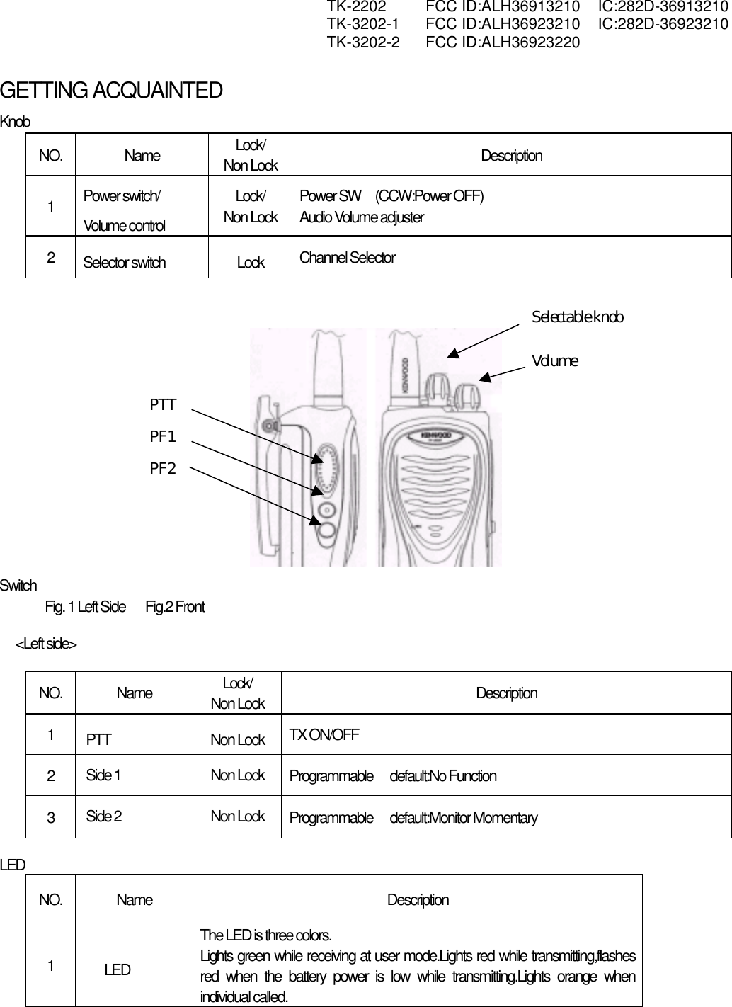
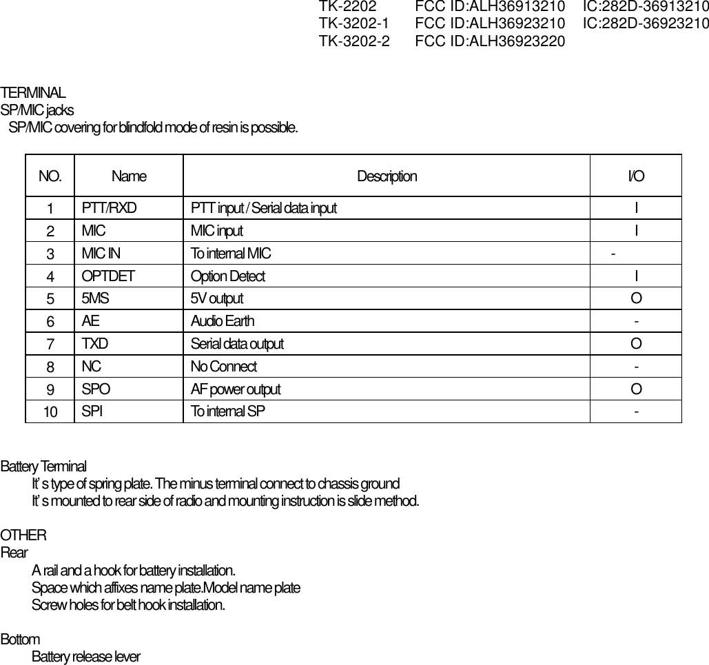
USERS MANUAL 1
Contents
1.
USERS MANUAL 1
2.
USERS MANUAL 2
USERS MANUAL 1
Navigation menu
Upload a User Manual
Namespaces
Wiki Guide
HTML
PDF
Info
Views
User Manual
Discussion / Help
Navigation