Kenwood USA 37333120 VHF/ FM HANDHELD TRANSCEIVER User Manual INSTRUCTION MANUAL
Kenwood USA Corporation VHF/ FM HANDHELD TRANSCEIVER INSTRUCTION MANUAL
UserManual.wiki
>
Kenwood USA
>
37333120 User Manual
USERS MANUAL
Navigation menu
Upload a User Manual
Namespaces
Wiki Guide
HTML
PDF
Info
Views
User Manual
Discussion / Help
Navigation
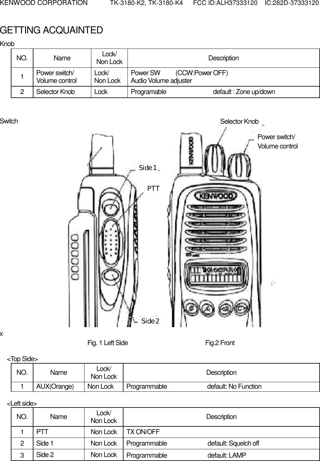
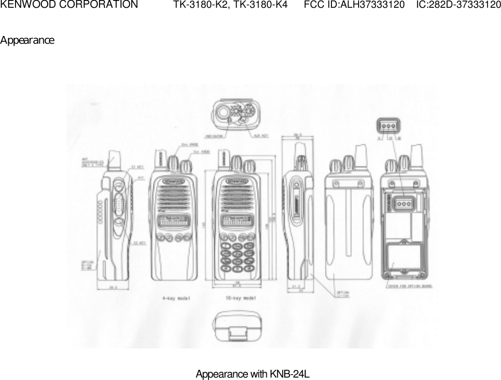
![KENWOOD CORPORATION TK-3180-K2, TK-3180-K4 FCC ID:ALH37333120 IC:282D-37333120 OPERATING BASICSATING BASICS § Switching Power ON/OFF Turn the Power switch/ Volume control clockwise to switch the transceiver ON. Turn the Power switch/ Volume control counterclockwise to switch the transceiver OFF. § Adjusting the Volume Rotate the Power switch/ Volume control to adjust the volume. § Selecting a Channel Pressing [<B], [C>] to select a channel. Pressing [C>] increases the channel number and pressing [<B] decreases it. § Making a Call 1 Select the desired channel. 2 Press the Side1 key (Programmed function Squelch off) to determine whether or not the current channel is being used. • If the channel is busy, wait until it becomes free. 3 Press and hold the PTT switch, then speak into the microphone in your normal voice. • For best results, hold the microphone approximately 3 to 4 cm (1 1/2 inches) from your lips. 4 Release the PTT switch to receive. AUXILIARY FEATURES § Time-out Timer (TOT) The TOT is used to automatically inhibit transmission after a specified time elapse. If the PTT switch is held down for longer than specified time, the transceiver will stop transmitting and a tone will sound. Release the PTT switch, then press it again to continue transmitting.](https://usermanual.wiki/Kenwood-USA/37333120/User-Guide-445670-Page-9.png)