Kenwood USA 378501 UHF FM Handheld/Portable/Mobile Transceiver User Manual Part 1
Kenwood USA Corporation UHF FM Handheld/Portable/Mobile Transceiver Part 1
Contents
- 1. User Manual Part 1
- 2. User Manual Part 2
- 3. User Manual Part 3
User Manual Part 1
NX-300-K2, NX-300-K4, TK-5320-K2, TK-5320-K4
FCC ID: ALH378501
IC: 282D-378501
INSTRUCTION MANUAL
NX-300
THANK YOU!
We are grateful you chose KENWOOD for your land mobile radio applications. We believe this easy-to-use transceiver
will provide dependable communications to keep personnel operating at peak efficiency.
KENWOOD transceivers incorporate the latest in advanced technology. As a result, we feel strongly that you will be
pleased with the quality and features of this product.
NOTICES TO THE USER
WARNING:
GOVERNMENT LAW PROHIBITS THE OPERATION OF UNLICENSED RADIO TRANSMITTERS WITHIN THE
TERRITORIES UNDER GOVERNMENT CONTROL.
ILLEGAL OPERATION IS PUNISHABLE BY FINE OR IMPRISONMENT OR BOTH.
REFER SERVICE TO QUALIFIED TECHNICIANS ONLY.
DO NOT OPERATE YOUR TRANSCEIVER IN EXPLOSIVE ATMOSPHERES (GASES, DUST, FUMES, ETC.).
TURN OFF YOUR TRANSCEIVER WHILE TAKING ON FUEL, OR WHILE PARKED IN GASOLINE SERVICE
STATIONS.
SAFETY:
It is important that the operator is aware of and understands hazards common to the operation of any transceiver.
WARNING:
EXPLOSIVE ATMOSPHERES (GASES, DUST, FUMES, etc.)
Turn off your transceiver while taking on fuel, or while parked in gasoline service stations.
One or more of the following statements may be applicable:
FCC WARNING
This equipment generates or uses radio frequency energy. Changes or modifications to this equipment may cause
harmful interference unless the modifications are expressly approved in the instruction manual. The user could lose the
authority to operate this equipment if an unauthorized change or modification is made.
INFORMATION TO THE DIGITAL DEVICE USER REQUIRED BY THE FCC
This equipment has been tested and found to comply with the limits for a Class B digital device, pursuant to Part 15 of
the FCC Rules.
These limits are designed to provide reasonable protection against harmful interference in a residential installation.
This equipment generates, uses and can generate radio frequency energy and, if not installed and used in accordance
with the instructions, may cause harmful interference to radio communications.
However, there is no guarantee that the interference will not occur in a particular installation. If this equipment does
cause harmful interference to radio or television reception, which can be determined by turning the equipment off and on,
the user is encouraged to try to correct the interference by one or more of the following measures:
· Reorient or relocate the receiving antenna.
· Increase the separation between the equipment and receiver.
· Connect the equipment to an outlet on a circuit different from that to which the receiver is connected.
· Consult the dealer for technical assistance.

NX-300-K2, NX-300-K4, TK-5320-K2, TK-5320-K4
FCC ID: ALH378501
IC: 282D-378501
ATTENTION (U.S.A. Only):
The RBRC Recycle seal found on KENWOOD nickel-cadmium (Ni-Cd) battery packs
indicates KENWOOD’s voluntary participation in an industry program to collect and
recycle Ni-Cd batteries after their operating life has expired. The RBRC program is an
alternative to disposing Ni-Cd batteries with your regular refuse or in municipal waste
streams, which is illegal in some areas.
For information on Ni-Cd battery recycling in your area, call (toll free)
1-800-8-BATTERY (1-800-822-8837). KENWOOD’s involvement in this program is
part of our commitment to preserve our environment and conserve our natural
resources.
UNPACKING AND CHECKING EQUIPMENT
Note:
The following unpacking instructions are for use by your
KENWOOD dealer, an authorized KENWOOD service facility, or the factory.
Carefully unpack the transceiver. We recommend that you identify the items listed in the following table before
discarding the packing material. If any items are missing or have been damaged during shipment, file a claim with the
carrier immediately.
§ Accessories
Quantity
Item Part Number K2
Belt Clip J29 - 0730 -*5 1
Screw N30 - 3008 - 60 2
Cap B09 - 0717 - *3 1
Screw N08 - 0564 - *4 1
NX-300-K2, NX-300-K4, TK-5320-K2, TK-5320-K4
FCC ID: ALH378501
IC: 282D-378501
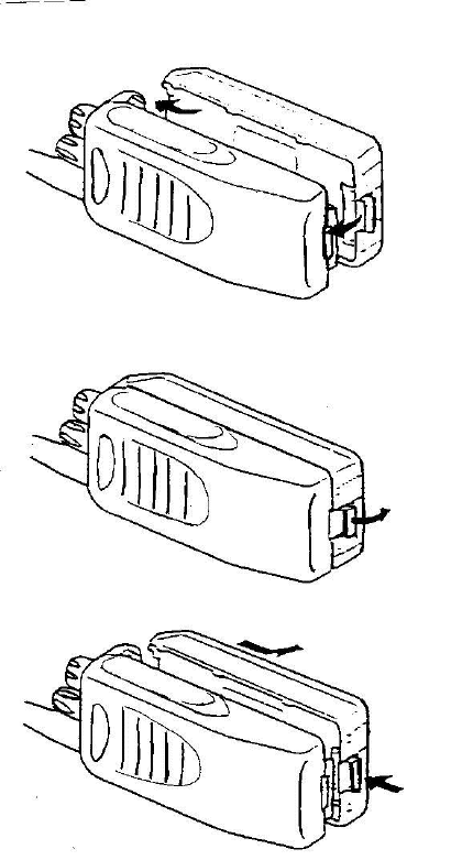
Installing/ Removing the Optional Battery Pack PREPARATION
The battery pack is not charged at the factory; charge it before use.
CAUTION:
DO NOT RECHARGE THE BATTERY PACK IF IT IS ALREADY FULLY CHARGED. DOING SO MAY CAUSE
HE LIFE OF THE BATTERY PACK TO SHORTEN OR THE BATTERY PACK MAY BE DAMAGED.
AFTER RECHARGING THE BATTERY PACK, DISCONNECT IT FROM THE CHARGER. IF THE CHARGER
POWER IS RESET (TURNED ON AFTER BEING TURNED OFF), RECHARGING WILL START AGAIN AND
THE BATTERY PACK WILL BECOME OVERCHARGED.
DO NOT SHORT THE BATTERY TERMINALS OR DISPOSE OF THE BATTERY BY FIRE.
NEVER ATTEMPT TO REMOVE THE CASING FROM THE BATTERY PACK.
1 Match the guides of the battery pack with the corresponding grooves on the upper rear of the transceiver, then firmly
press the battery pack t
2 Flip the safety catch into place to prevent accidentally pressing the release latch and removing the battery.
3 To remove the battery pack, lift the safety catch, press the release latch,then pull the battery pack away from the
transceiver.
NX-300-K2, NX-300-K4, TK-5320-K2, TK-5320-K4
FCC ID: ALH378501
IC: 282D-378501
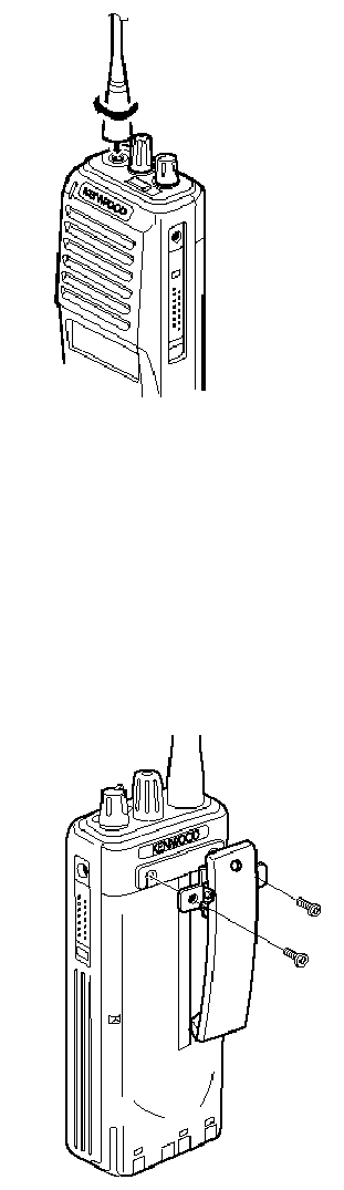
Installing the Antenna
Screw the antenna into the connector on the top of the transceiver by holding the antenna at its base and
turning it clockwise until secure.
Installing the Belt Clip
If necessary, attach the belt clip using the two supplied 3 x 6 mm screws.
Notes: If the belt clip is not installed, its mounting location may get hot during continuous transmission or when left sitting
in a hot environment.
NX-300-K2, NX-300-K4, TK-5320-K2, TK-5320-K4
FCC ID: ALH378501
IC: 282D-378501
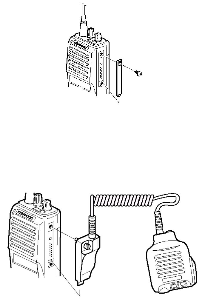
Installing the Cap over the Speaker/Microphone Jacks
If you are not using an optional KMC-25 speaker/ microphone, install the cover over the univeral connector using the
supplied 4 x 6 mm screw.
Installing the Optional Speaker/ Microphone
1 Insert the guide of the speaker/ microphone connector into the groove of the universalconnector.
2 Secure the connecter in place using the attached screw.
NX-300-K2, NX-300-K4, TK-5320-K2, TK-5320-K4
FCC ID: ALH378501
IC: 282D-378501
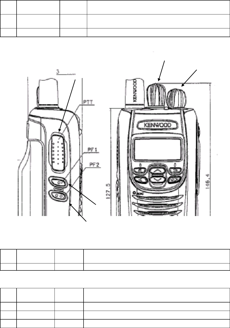
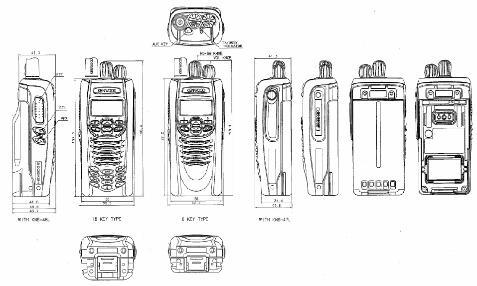
GETTING ACQUAINTED
Knob
NO. Name Lock/
Non Lock Description
1 Power switch/
Volume control Lock/
Non Lock Power SW (CCW:Power OFF)
Audio Volume adjuster
2 Selector Knob Lock Programmable default : CH/GID Select
Switch
Fig. 1 Left Side Fig.2 Front
<Top Side>
NO. Name Lock/
Non Lock Description
1 AUX(Orange) Non Lock Programmable default: No Function
<Left side>
NO. Name Lock/
Non Lock Description
1 PTT Non Lock TX ON/OFF
2 Side 1 Non Lock Programmable default: Squelch off momentary
3 Side 2 Non Lock Programmable default: Backlight
Selector Knob Power switch/
Volume control
Side 1
PTT
Side 2

NX-300-K2, NX-300-K4, TK-5320-K2, TK-5320-K4
FCC ID: ALH378501
IC: 282D-378501
<Front Side>
NO. Name Description
1 U1 Programmable default: Zone Up
2 D1 Programmable default: NoneZone Down
3 P1 Programmable default: None
4 P2 Programmable default: CH/GID Up
5 P3 Programmable default: None
6 P4 Programmable default: None
LED
NO. Name Description
1 LED
The LED is three colors.
Lights green while receiving at user mode. Light red while transmitting,
flashes red when the battery power is low .Lights orange when
individual called.
TERMINAL
Universal connector
Universal connector covering for blindfold mode of resin is possible.
NO. Name Description Impedance I/O
1 SSW Ext/Int Speaker Switch Input High Impedance I
2 SP+ BTL Output + for External Speaker 8 ohm O
3 SP- BTL Output - for External Speaker 16 ohm O
4 MSW Ext/Int MIC Switch Input High Impedance I
5 EMC External MIC Input 1.8 k ohm I
6 ME External MIC GND GND -
7 PTT External PTT Input High Impedance I
8 PF Programable Function Key Input High Impedance I
9 OPT Man Down Input High Impedance I
10 E GND GND -
11 5U 5V 5V O
12 TXD Serial Data Output CMOS O
13 RXD Serial Data Input CMOS I
14 NC Reserve - --
Antenna Terminal
Impedance is 50 ohm
Battery Terminal
It’s type of spring plate. The minus terminal connect to chassis ground
It’s mounted rear side of radio and mounting instruction is slide method.
OTHER
Rear A rail and a hook for battery installation.
Space which affixes name plate.Model name plate
Screw hole for belt hook installation.
Bottom
Battery release lever
NX-300-K2, NX-300-K4, TK-5320-K2, TK-5320-K4
FCC ID: ALH378501
IC: 282D-378501
Appearance
Appearance with KNB-47L/48L
NX-300-K2, NX-300-K4, TK-5320-K2, TK-5320-K4
FCC ID: ALH378501
IC: 282D-378501
OPERATING BASICSATING BASICS
§ Switching Power ON/OFF
Turn the Power switch/ Volume control clockwise to switch the transceiver ON.
Turn the Power switch/ Volume control counterclockwise to switch the transceiver OFF.
§ Adjusting the Volume
Rotate the Power switch/ Volume control to adjust the volume.
§ Selecting a Channel
Pressing [<B], [C>] to select a channel.
Pressing [C>] increases the channel number and pressing [<B] decreases it.
§ Making a Call
1 Select the desired channel.
2 Press the Side1 key (Programmed function Squelch off) to determine whether or not the current channel is being
used.
• If the channel is busy, wait until it becomes free.
3 Press and hold the PTT switch, then speak into the microphone in your normal voice.
• For best results, hold the microphone approximately 3 to 4 cm (1 1/2 inches) from your lips.
4 Release the PTT switch to receive.
AUXILIARY FEATURES
§ Time-out Timer (TOT)
The TOT is used to automatically inhibit transmission after a specified time elapse. If the PTT switch is held down for
longer than specified time, the transceiver will stop transmitting and a tone will sound. Release the PTT switch, then
press it again to continue transmitting.
Radio FRequency eneRgy SaFety inFoRmation
This KENWOOD transceiver has been tested and complies with the standards listed below, in regards
to Radio Frequency (RF) energy and electromagnetic energy (EME) generated by the transceiver.
• FCC RF exposure limits for
Occupational Use Only
. RF Exposure limits adopted by the FCC are generally
based on recommendations from the National Council on Radiation Protection and Measurements, & the
American National Standards Institute.
• FCC OET Bulletin 65 Edition 97-01 Supplement C
• American National Standards Institute (C95.1 – 1992)
• American National Standards Institute (C95.3 – 1992)
This KENWOOD transceiver generates RF EME while transmitting. RF EME (Radio Frequency Electric &
Magnetic Energy) has the potential to cause slight thermal, or heating effects to any part of your body less
than the recommended distance from this radio transmitter’s antenna. RF energy exposure is determined
primarily by the distance to and the power of the transmitting device. In general, RF exposure is minimized
when the lowest possible power is used or transmission time is kept to the minimum required for consistent
communications, and the greatest distance possible from the antenna to the body is maintained. The
transceiver has been designed for and is classied for
Occupational Use Only
. Occupational/ controlled
exposure limits are applicable to situations in which persons are exposed to RF energy as a consequence
of their employment, and such persons have been made aware of the potential for exposure and can
exercise control over their exposure. This means you can use the transceiver only if you are aware of
the potential hazards of operating a transceiver and are familiar in ways to minimize these hazards. This
transceiver is not intended for use by the general public in uncontrolled environments. Uncontrolled
environment exposure limits are applicable to situations in which the general public may be exposed to RF
energy, or in which the persons who are exposed as a consequence of their employment may not be fully
aware of the potential for exposure or cannot exercise control over their exposure.
The following list provides you with the information required to ensure that you are aware of RF
exposure and of how to operate this transceiver so that the FCC RF exposure limitations are not
exceeded.
• While transmitting (holding the PTT switch or speaking with VOX enabled), always keep the antenna
and the radio at least 3 cm (1 3/16 inches) from your body or face, as well as from any bystanders. A
LED on the top of the radio shows red when the transmitter is operating in both PTT and VOX modes.
• Do not transmit for more than 50% of the total transceiver use time; transmitting over 50% of the total use
time may exceed the limits in accordance to the FCC RF exposure requirements. Nominal transceiver
operation is 5% transmission time, 5% reception time, and 90% stand-by time.
• Use only the specied antenna for this transceiver; this may be either the antenna provided with the
transceiver or another antenna authorized by KENWOOD.
Use only KENWOOD authorized accessories (antennas, battery packs, belt clips, Speaker/ Mics
or headsets etc.): When worn on the body, always place the radio in a KENWOOD recommended
clip or carrying case meant for this product. The use of other than recommended or approved
body- worn accessories may result in RF exposure levels which exceed the FCC’s occupational/
controlled environment RF exposure limits.
To ensure that your exposure to RF EME is within the FCC limits for occupational use, you must
observe and adhere to the above points.
Electromagnetic Interference Compatibility
Electronic devices are susceptible to electromagnetic interference (EMI) if they are not adequately
shielded or designed for electromagnetic compatibility. Because this transceiver generates RF
energy, it can cause interference to such equipment.
• Turn OFF your transceiver where signs are posted to do so. Hospitals and health care facilities use
equipment that is sensitive to electromagnetic radiation.
• Turn OFF your transceiver while on board an aircraft when so instructed. Use of the transceiver must
be in accordance with airline regulations and/or crew instructions.
B59-2448-00