Kenwood USA 39913110 UHF P25 Transceiver User Manual TK 5210 E 00 Cover
Kenwood USA Corporation UHF P25 Transceiver TK 5210 E 00 Cover
users manual

© B62-xxxx-00 (K)
09 08 07 06 05 04 03 02 01 00
INSTRUCTION MANUAL
UHF APCO P25 TRANSCEIVER
TK-5310

THANK YOU
We are grateful you chose KENWOOD for your land mobile
radio applications. We believe this easy-to-use transceiver
will provide dependable communications to keep personnel
operating at peak efficiency.
KENWOOD transceivers incorporate the latest in advanced
technology. As a result, we feel strongly that you will be
pleased with the quality and features of this product.
NOTICES TO THE USER
◆Government law prohibits the operation of unlicensed radio
transmitters within the territories under government control.
◆Illegal operation is punishable by fine and/or imprisonment.
◆Refer service to qualified technicians only.
SAFETY: It is important that the operator is aware of and
understands hazards common to the operation of any
transceiver.
This device made under license under one or more of the
following US Patents: 4,590,473; 4,636,791; 4,716,407;
4,972,460; 5,148,482; 5,185,796; 5,271,017; 5,377,229;
5,502,767.
The IMBE™ voice coding Technology embodied in this
product is protected by intellectual property rights including
patent rights, copyrights, and trade secrets of Digital Voice
Systems, Inc. This voice coding Technology is licensed solely
for use within this Communications Equipment. The user of
this Technology is explicitly prohibited from attempting to
decompile, reverse engineer, or disassemble the Object
Code, or in any other way convert the Object Code into a
human-readable form.

i
One or more of the following statements may be applicable:
FCC WARNING
This equipment generates or uses radio frequency energy. Changes
or modifications to this equipment may cause harmful interference
unless the modifications are expressly approved in the instruction
manual. The user could lose the authority to operate this equipment
if an unauthorized change or modification is made.
INFORMATION TO THE DIGITAL DEVICE USER REQUIRED BY
THE FCC
This equipment has been tested and found to comply with the limits
for a Class B digital device, pursuant to Part 15 of the FCC Rules.
These limits are designed to provide reasonable protection against
harmful interference in a residential installation.
This equipment generates, uses and can generate radio frequency
energy and, if not installed and used in accordance with the
instructions, may cause harmful interference to radio communications.
However, there is no guarantee that the interference will not occur in a
particular installation. If this equipment does cause harmful
interference to radio or television reception, which can be determined
by turning the equipment off and on, the user is encouraged to try to
correct the interference by one or more of the following measures:
•Reorient or relocate the receiving antenna.
•Increase the separation between the equipment and receiver.
•Connect the equipment to an outlet on a circuit different from that
to which the receiver is connected.
•Consult the dealer for technical assistance.

ii
The RBRC Recycle seal found on KENWOOD
nickel-cadmium (Ni-Cd) battery packs indicates
KENWOOD’s voluntary participation in an industry
program to collect and recycle Ni-Cd batteries after
their operating life has expired. The RBRC
program is an alternative to disposing Ni-Cd
batteries with your regular refuse or in municipal
waste streams, which is illegal in some areas.
For information on Ni-Cd battery recycling in your area, call (toll free)
1-800-8-BATTERY (1-800-822-8837).
KENWOOD’s involvement in this program is part of our commitment
to preserve our environment and conserve our natural resources.
The RBRC Recycle seal found on KENWOOD
nickel metal hydride (Ni-MH) battery packs
indicates KENWOOD’s voluntary participation in an
industry program to collect and recycle Ni-MH
batteries after their operating life has expired. The
RBRC program is an alternative to disposing Ni-MH
batteries with your regular refuse or in municipal
waste streams, which is illegal in some areas.
For information on Ni-MH battery recycling in your area, call (toll free)
1-800-8-BATTERY (1-800-822-8837).
KENWOOD’s involvement in this program is part of our commitment
to preserve our environment and conserve our natural resources.
The RBRC Recycle seal found on KENWOOD
lithium-ion (Li-ion) battery packs indicates
KENWOOD’s voluntary participation in an industry
program to collect and recycle Li-ion batteries after
their operating life has expired. The RBRC
program is an alternative to disposing Li-ion
batteries with your regular refuse or in municipal
waste streams, which is illegal in some areas.
For information on Li-ion battery recycling in your area, call (toll free)
1-800-8-BATTERY (1-800-822-8837).
KENWOOD’s involvement in this program is part of our commitment
to preserve our environment and conserve our natural resources.

iii
PRECAUTIONS
•Do not charge the transceiver and battery pack when they are
wet.
•Ensure that there are no metallic items located between the
transceiver and the battery pack.
•Do not use options not specified by KENWOOD.
•If the die-cast chassis or other transceiver part is damaged, do
not touch the damaged parts.
•If a headset or headphone is connected to the transceiver, reduce
the transceiver volume. Pay attention to the volume level when
turning the squelch off.
•Do not place the microphone cable around your neck while near
machinery that may catch the cable.
•Do not place the transceiver on unstable surfaces.
•Ensure that the end of the antenna does not touch your eyes.
•When the transceiver is used for transmission for many hours, the
radiator and chassis will become hot. Do not touch these
locations when replacing the battery pack.
•Do not immerse the transceiver in water.
•When water gets into the microphone opening or the speaker
grill, the voice level may become incoherent or distorted. Lightly
shake the transceiver to remove the water from the speaker and/
or microphone before operating the transceiver.

iv
Turn the transceiver power off in the following locations:
•In explosive atmospheres (inflammable gas, dust particles,
metallic powders, grain powders, etc.).
•While taking on fuel or while parked at gasoline service stations.
•Near explosives or blasting sites.
•In aircrafts.
•In medical institutions or near persons using pacemakers.
•Do not disassemble or modify the transceiver for any reason.
•Do not place the transceiver on or near airbag equipment while
the vehicle is running. When the airbag inflates, the transceiver
may be ejected and strike the driver or passengers.
•Do not transmit while touching the antenna terminal or if any
metallic parts are exposed from the antenna covering.
Transmitting at such a time may result in a high-frequency burn.
•If an abnormal odor or smoke is detected coming from the
transceiver, switch the transceiver power off immediately, remove
the battery pack from the transceiver, and contact your
KENWOOD dealer.
•Use of the transceiver while you are driving may be against traffic
laws. Please check and observe the vehicle regulations in your
area.
•Do not expose the transceiver to extremely hot or cold
conditions.

v
CONTENTS
UNPACKING AND CHECKING EQUIPMENT .......................... 1
SUPPLIED ACCESSORIES ................................................ 1
PREPARATION .......................................................... 2
BATTERY PACK PRECAUTIONS ........................................... 2
INSTALLING/ REMOVING THE (OPTIONAL) BATTERY PACK ................... 7
INSTALLING THE (OPTIONAL) ANTENNA ................................... 8
INSTALLING THE BELT CLIP .............................................. 8
INSTALLING THE CAP OVER THE UNIVERSAL CONNECTOR .................... 9
INSTALLING THE (OPTIONAL) SPEAKER/ MICROPHONE OR HEADSET ......... 9
GETTING ACQUAINTED .............................................. 10
DISPLAY (K2 AND K3 MODELS ONLY) ................................ 13
PROGRAMMABLE FUNCTIONS ..................................... 15
BASIC OPERATIONS ................................................. 18
SWITCHING POWER ON/ OFF ........................................ 18
ADJUSTING THE VOLUME .............................................. 19
SELECTING A ZONE AND CHANNEL ..................................... 19
TRANSMITTING ....................................................... 20
RECEIVING ........................................................... 22
SCAN .................................................................. 23
TEMPORARY CHANNEL LOCKOUT ....................................... 23
PRIORITY SCAN ...................................................... 24
SCAN REVERT ....................................................... 24
SCAN PROGRAMMING (K2 AND K3 MODELS ONLY) .................... 25
FleetSync: ALPHANUMERIC 2-WAY PAGING FUNCTION ........ 26
SELCALL (SELECTIVE CALLING) ........................................ 26
STATUS MESSAGE (K2 AND K3 MODELS ONLY) ........................ 27
SHORT MESSAGES ................................................... 29
LONG MESSAGES .................................................... 29

vi
(CONTENTS CONTINUED…)
DTMF (DUAL TONE MULTI FREQUENCY) CALLS ................. 30
MAKING A DTMF CALL (K3 MODELS ONLY) .......................... 30
AUTODIAL (K2 AND K3 MODELS ONLY) ............................... 31
STUN CODE ......................................................... 31
EMERGENCY CALLS ................................................. 32
SCRAMBLER (FM)/ ENCRYPTION (APCO) ......................... 33
SECURE (ENCRYPTED) TRANSMISSION .................................. 33
SELECTING THE SCRAMBLER CODE ..................................... 33
SELECTING THE ENCRYPTION KEY ...................................... 34
DELETING THE ENCRYPTION KEY (K2 AND K3 MODELS ONLY) ........... 34
PASSWORD PROTECTION (K2 AND K3 MODELS ONLY) .................. 34
SIGNALING ............................................................ 35
QUIET TALK (QT)/ DIGITAL QUIET TALK (DQT) ....................... 35
OPTIONAL SIGNALING ................................................. 36
VOICE OPERATED TRANSMISSION (VOX) ......................... 37
VOX GAIN LEVEL .................................................... 37
VOX OPERATION .................................................... 38
CLOCK (K2 and K3 Models Only) ................................... 39
CLOCK ADJUSTMENT .................................................. 39
ADVANCED OPERATIONS ............................................ 40
BACKGROUND OPERATIONS ....................................... 49
TIME-OUT TIMER (TOT) ............................................. 49
BATTERY SAVER ...................................................... 49
LOW BATTERY WARNING ............................................. 50
COMPANDER ......................................................... 50
PTT ID ............................................................. 51
BUSY CHANNEL LOCKOUT (BCL) ..................................... 51
1
UNPACKING AND CHECKING EQUIPMENT
Note: The following unpacking instructions are for use by your
KENWOOD dealer, an authorized KENWOOD service facility, or the
factory.
Carefully unpack the transceiver. We recommend that you
identify the items listed in the following table before discarding
the packing material. If any items are missing or have been
damaged during shipment, file a claim with the carrier
immediately.
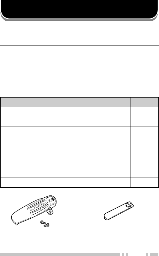
SUPPLIED ACCESSORIES
Belt clip + screws Universal
connector cap
metI rebmuNtraP ytitnauQ
pilctleBXX-0170-92J1
•pilctlebrofswercSXX-8003-03N2
pacrotcennoclarevinUXX-2860-90B1
•wercsgnisserD
)delbmessaerp( XX-1350-80N1
•laesrebbuR
)delbmessaerp( XX-0434-11G1
dracecnereferkciuQXX-3932-95B1
launamnoitcurtsnIXX-6971-26B1

2
PREPARATION
BATTERY PACK PRECAUTIONS
Do not use battery packs or battery chargers not
recommended by KENWOOD.
◆Do not recharge the battery pack if it is already fully charged.
Doing so may cause the life of the battery pack to shorten or the
battery pack may be damaged.
◆After charging the battery pack, disconnect it from the charger. If
the charger power is reset (turned ON after being turned OFF),
recharging will start again and the battery pack will become
overcharged.
◆Do not use the transceiver while charging the battery pack. We
recommend you switch the transceiver power OFF while
charging is taking place.
◆Do not charge the battery pack when the battery pack or
transceiver is wet, to avoid the risk of fire or damage. Wipe the
water from the battery pack or transceiver using a dry cloth
before charging.
◆Do not short the battery terminals or dispose of the battery by
fire.
◆Never attempt to remove the casing from the battery pack.
■Charging the Battery Pack
For charging procedures, refer to the battery charger
Instruction Manual.

3
Information concerning the (optional) Li-ion battery pack:
The battery pack includes flammable objects such as organic solvent.
Mishandling may cause the battery to rupture producing flames or
extreme heat, deteriorate, or cause other forms of damage to the battery.
Please observe the following prohibitive matters.
•Do not disassemble or reconstruct battery!
The battery pack has a safety function and protection circuit to
avoid danger. If they suffer serious damage, the battery may
generate heat or smoke, rupture, or burst into flame.
•Do not short-circuit the battery!
Do not join the + and – terminals using any form of metal (such
as a paper clip or wire). Do not carry or store the battery pack in
containers holding metal objects (such as wires, chain-necklace
or hairpins). If the battery pack is short-circuited, excessive
current will flow and the battery may generate heat or smoke,
rupture, or burst into flame. It will also cause metal objects to
heat up.
•Do not incinerate or apply heat to the battery!
If the insulator is melted, the gas release vent or safety function is
damaged, or the electrolyte is ignited, the battery may generate
heat or smoke, rupture, or burst into flame.
•Do not use or leave the battery near fires, stoves, or other
heat generators (areas reaching over 80°C/ 176°F)!
If the polymer separator is melted due to high temperature, an
internal short-circuit may occur in the individual cells and the
battery may generate heat or smoke, rupture, or burst into flame.
•Avoid immersing the battery in water or getting it wet by
other means!
If the battery becomes wet, wipe it off with a dry towel before use.
If the battery’s protection circuit is damaged, the battery may
charge at extreme current (or voltage) and an abnormal chemical
reaction may occur. The battery may generate heat or smoke,
rupture, or burst into flame.
DANGER

4
•Do not charge the battery near fires or under direct sunlight!
If the battery’s protection circuit is damaged, the battery may
charge at extreme current (or voltage) and an abnormal chemical
reaction may occur. The battery may generate heat or smoke,
rupture, or burst into flame.
•Use only the specified charger and observe charging
requirements!
If the battery is charged in unspecified conditions (under high
temperature over the regulated value, excessive high voltage or
current over regulated value, or with a remodelled charger), it
may overcharge or an abnormal chemical reaction may occur.
The battery may generate heat or smoke, rupture, or burst into
flame.
•Do not pierce the battery with any object, strike it with an
instrument, or step on it!
This may break or deform the battery, causing a short-circuited.
The battery may generate heat or smoke, rupture, or burst into
flame.
•Do not jar or throw the battery!
An impact may cause the battery to leak, generate heat or
smoke, rupture, and/or burst into flame. If the battery’s protection
circuit is damaged, the battery may charge at an abnormal
current (or voltage), and an abnormal chemical reaction may
occur.
•Do not use the battery pack if it is damaged in any way!
The battery may generate heat or smoke, rupture, or burst into
flame.
•Do not solder directly onto the battery!
If the insulator is melted or the gas release vent or safety function
is damaged, the battery may generate heat or smoke, rupture, or
burst into flame.
•Do not reverse the battery polarity (and terminals)!
When charging a reversed battery, an abnormal chemical
reaction may occur. In some cases, an unexpected large amount
of current may flow upon discharging. The battery may generate
heat or smoke, rupture, or burst into flame.

5
•Do not charge the battery for longer than the specified time!
If the battery pack has not finished charging even after the
regulated time has passed, stop it. The battery may generate
heat or smoke, rupture, or burst into flame.
•Do not place the battery pack into a microwave or high
pressure container!
The battery may generate heat or smoke, rupture, or burst into
flame.
•Keep ruptured and leaking battery packs away from fire!
If the battery pack is leaking (or the battery emits a bad odor),
immediately remove it from flammable areas. Electrolyte leaking
from battery can easily catch on fire and may cause the battery to
generate smoke or burst into flame.
•Do not use an abnormal battery!
If the battery pack emits a bad odor, appears to have different
coloring, is deformed, or seems abnormal for any other reason,
remove it from the charger or operating equipment and do not
use it. The battery may generate heat or smoke, rupture, or burst
into flame.
•Do not reverse-charge or reverse-connect the battery!
The battery pack has positive and negative poles. If the battery
pack does not smoothly connect with a charger or operating
equipment, do not force it; check the polarity of the battery. If the
battery pack is reverse-connected to the charger, it will be
reverse-charged and an abnormal chemical reaction may occur.
The battery may generate heat or smoke, rupture, or burst into
flame.
•Do not touch a ruptured and leaking battery!
If the electrolyte liquid from the battery gets into your eyes, wash
your eyes out with fresh water as soon as possible, without
rubbing your eyes. Go to the hospital immediately. If left
untreated, it may cause eye-problems.

6
■Using the Li-ion Battery Pack
•Charge the battery pack before using it.
•To keep the battery discharge at a minimum, remove the
battery pack from the equipment when it is not in use. Store
the battery pack in a cool and dry location.
•When storing the battery pack for a long period:
1Remove the battery pack from the equipment.
2Discharge the battery pack, if possible.
3Store the battery pack in a cool (below 25°C/ 77°F) and
dry location.
■Characteristics of the Li-ion Battery Pack
•As the battery pack is charged and discharged repeatedly, the
battery capacity decreases.
•Even if the battery pack is unused, the battery pack
degrades.
•It takes a longer time to charge the battery pack in cooler
areas.
•The life of battery pack is shortened when it is charged and
discharged in hotter areas. When the battery pack is stored
in a hot location, the battery pack degrades quicker. Do not
leave the battery pack in vehicles or near heating appliances.
•When the battery pack operating time becomes short, even if
it is fully charged, replace the battery pack. Continuing to
charge and discharge the battery pack may result in
electrolyte leakage.
7
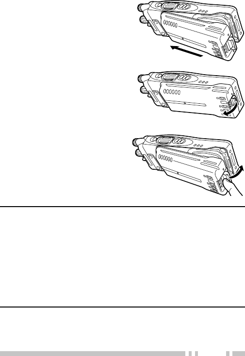
INSTALLING/ REMOVING THE (OPTIONAL) BATTERY PACK
1Match the guides of the
battery pack with the
corresponding grooves on
the upper rear of the
transceiver, then firmly press
the battery pack to lock it in
place.
2Lock the safety catch to
prevent accidentally pressing
the release latch and
removing the battery pack.
3To remove the battery pack,
lift the safety catch, press the
release latch, then pull the
battery pack away from the
transceiver.
Note:
◆To lift the battery pack safety catch, use a piece of hardened
plastic or metal, such as a screwdriver, that is no more than 6 mm
wide and 1 mm thick. It is imperative that you place the
implement under only the lip of the safety catch so that you do
not damage the release latch.
◆Before charging a battery pack that is attached to the transceiver,
ensure that the safety catch is firmly closed.
◆While operating the transceiver using a Li-ion or Ni-MH battery
pack in areas with an ambient temperature of –10°C/ +14°F and
lower, operating time may be shortened.
8
Optional
antenna
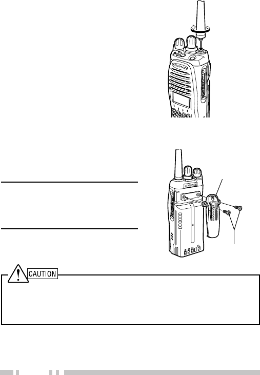
INSTALLING THE (OPTIONAL) ANTENNA
Screw the antenna into the
connector on the top of the
transceiver by holding the
antenna at its base and turning
it clockwise until secure.
INSTALLING THE BELT CLIP
If necessary, attach the belt clip
using the two supplied 3 x 8 mm
binding screws.
Note: If the belt clip is not
installed, its mounting location may
get hot during continuous
transmission or when left sitting in
a hot environment.
Binding screws
Belt clip
Do not use glue which is designed to prevent screw loosening when
installing the belt clip, as it may cause damage to the transceiver.
Acrylic ester, which is contained in these glues, may crack the
transceiver’s back panel.
9
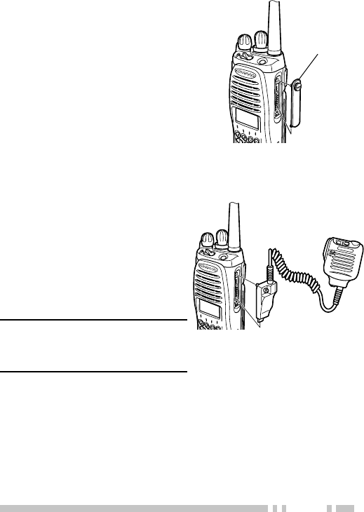
INSTALLING THE CAP OVER THE UNIVERSAL CONNECTOR
1If you are not using an
optional speaker/
microphone or headset,
install the cap over the
universal connector.
2Secure the cap in place
using the attached screw.
Universal
connector cap
INSTALLING THE (OPTIONAL) SPEAKER/ MICROPHONE OR HEADSET
Optional
speaker/ microphone
1Insert the guide of the
speaker/ microphone or
headset connector into the
groove of the universal
connector.
2Secure the connector in
place using the attached
screw.
Note: When not using an optional
speaker/ microphone or headset,
install the cap over the universal
connector.
10
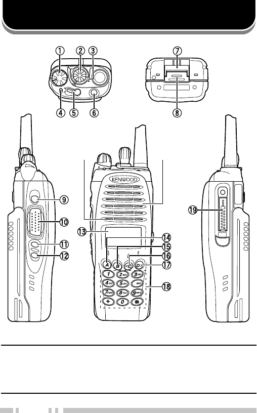
GETTING ACQUAINTED
A
B
C
6
MIC
Microphone Speaker
There are 3 models available:
K model: Basic model.
K2 model: Equipped with a display and 4-key keypad (A, B, <C, and D>).
K3 model: Equipped with a display and full keypad.
The above illustration displays the K3 model.

11
qq
qq
qPower switch/ Volume control
Turn clockwise to switch the transceiver ON. Rotate to
adjust the volume. Turn counterclockwise fully to switch
the transceiver OFF.
ww
ww
wSelector knob
Rotate this control to activate its programmable function
{page 15}. The default setting is Channel Select.
ee
ee
eConcentric switch
Rotate this switch to activate one of its programmable
functions {page 15}.
rr
rr
rTransmit/ Receive/ Battery low indicator
Lights red while transmitting. Lights green while receiving,
and orange when receiving an encoded call (i.e. 2-tone,
DTMF signaling, etc.). Flashes red when the battery power
is low while transmitting. Replace or recharge the battery
pack when the battery power is low.
Note: This indicator can be disabled by your dealer.
tt
tt
tLever switch
Switch the toggle position to activate its programmable
function {page 15}. The O position turns the function ON.
The ● position turns the function OFF.
yy
yy
yAuxiliary (orange) key
Press to activate its programmable function {page 15}.
uu
uu
uSafety catch
Lock this catch to avoid accidentally pressing the release
latch and removing the battery pack {page 7}.
ii
ii
iRelease latch
Press the release latch to unlock and remove the battery
pack {page 7}.
oo
oo
oSide 1 key
Press to activate its programmable function {page 15}.
!0!0
!0!0
!0 PTT (Push-To-Talk) switch
Press and hold this switch, then speak into the
microphone to call a station.

12
!1!1
!1!1
!1 Side 2 key
Press to activate its programmable function {page 15}.
Acts as an Up key for certain transceiver settings.
!2!2
!2!2
!2 Side 3 key
Press to activate its programmable function {page 15}.
Acts as a Down key for certain transceiver settings.
!3!3
!3!3
!3 Display (K2 and K3 models only)
Refer to the display on page 13.
!4!4
!4!4
!4 A key (K2 and K3 models only)
Press to activate its programmable function {page 15}.
The programmed name appears on the bottom of the
display.
!5!5
!5!5
!5 B key (K2 and K3 models only)
Press to activate its programmable function {page 15}.
The programmed name appears on the bottom of the
display.
!6!6
!6!6
!6 <C key (K2 and K3 models only)
Press to activate its programmable function {page 15}.
The programmed name appears on the bottom of the
display. Also acts as a Down key for certain transceiver
settings.
!7!7
!7!7
!7 D> key (K2 and K3 models only)
Press to activate its programmable function {page 15}.
The programmed name appears on the bottom of the
display. Also acts as an Up key for certain transceiver
settings.
!8!8
!8!8
!8 Keypad (K3 models only)
Press the keys on the keypad to send DTMF tones or the
keypad keys can also be programmed with the functions
listed on page 15 if one of the other programmable
function keys is programmed as Function.
!9!9
!9!9
!9 Universal connector
Connect the (optional) speaker/ microphone here.
Otherwise, keep the supplied cap in place.
13
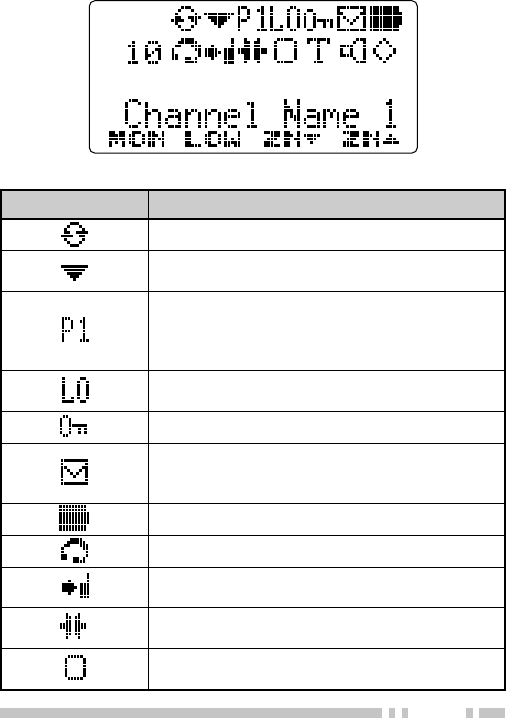
DISPLAY (K2 AND K3 MODELS ONLY)
rotacidnI noitpircseD
.edomnacSgnisuerauoynehwsraeppA
ehtotdeddasilennahctnerrucehtnehwsraeppA
.ecneuqesgninnacs
demmargorpsilennahctnerrucehtnehwsraeppA
ytiroirPstneserper”1P“.lennahcytiroirPasa
.2lennahcytiroirPstneserper”2P“.1lennahc
.2dna1slennahcytiroirPstneserper”PP“
”IH“.detcelessirewoptimsnartwolnehwsraeppA
.rewoptimsnarthgihgnisunehwsraeppa
.detavitcasinoitcnufkcolyekehtnehwsraeppA
ehtniderotsegassemasierehtnehwsraeppA
wenanehwsehsalF.yromemreviecsnart
.devirrasahegassem
.sutatsrewopyrettabtnerrucehtsyalpsiD
.detavitcasinoitcnufXOVehtnehwsraeppA
sinoitcnufdnuorAklaTehtnehwsraeppA
.detavitca
sinoitcnufrednapmoclanretniehtnehwsraeppA
.evitca
enoTelbatceleSrotarepOehtnehwsraeppA
.detavitcasinoitcnuf
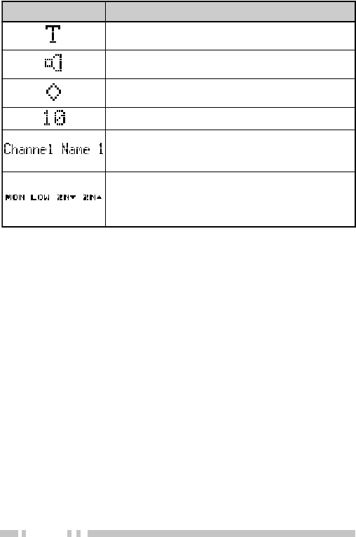
14
rotacidnI noitpircseD
sinoitcnufpuorGlacitcaTehtnehwsraeppA
.detavitca
dnadetavitcasinoitcnufrotinomehtnehwsraeppA
.detavitcasinoitcnufffohcleuqsehtnehw
sinoitcnufnoitpyrcne/relbmarcsehtnehwsraeppA
.detavitca
.rebmunenozgnitarepoehtsyalpsiD
rebmunlennahcdnaenozgnitarepoehtsyalpsiD
txetsuoiravsyalpsidoslA.emanlennahcro
.desugniebnoitcnufehtnognidnepedsegassem
ehtfosnoitcnufehtsyalpsiD A,B,C< dna, >D
ehtybraeppasemannoitcnufdetaiverbbA.syek
nognitratssnoitpircsedehtnisemannoitcnuflluf
.04egap

15
PROGRAMMABLE FUNCTIONS
Refer to the following tables to determine which functions are
available for appropriate channels.
Conventional FM: Channels set up for Conventional FM
Operation
Conventional APCO: Channels set up for Conventional
APCO Operation
✓ : Available
• : Mixed Mode only
N/A: Not Available
noitcnuFelbammargorP lanoitnevnoC
MF
lanoitnevnoC
OCPA
ecnerefeR
egaP
laidotuA
1
✓A/N04,13
sutatSyrettaB ✓✓
04
esnopseRllaCA/N ✓04
nwoDlennahC ✓✓
04
llaceRlennahC ✓✓
04
tceleSlennahC
2
✓✓
14
pUlennahC ✓✓
14
kcolC
1
✓✓
14,93
5~1lennahCtceriD ✓✓
14
retcarahCyalpsiD
1
✓✓
14
ycnegremE
3
✓✓
14,23
rekaepSlanretxE ✓✓
24
noitcnuF ✓✓
24
lennahCemoH ✓✓
24
laudividnI
1
A/N ✓24,12
eteleDyeK
1
A/N ✓24,43
kcoLyeK ✓✓
34

16
noitcnuFelbammargorP lanoitnevnoC
MF
lanoitnevnoC
OCPA
ecnerefeR
egaP
thgiL
1
✓✓
34
rewoPtimsnarTwoL ✓✓
34
rotinoM ✓✓
44
yratnemoMrotinoM ✓✓
44
enoN ✓✓
44
elbatceleSrotarepO
enoT
1
✓•44,53
nwoDTSO
1
✓•44
pUTSO
1
✓•54
nacS ✓✓
54,32
eteleDnacS ✓✓
54,32
margorPnacS
1
✓✓
54,42
noitpyrcnE/relbmarcS ✓✓
54,33
noitpyrcnE/relbmarcS
edoC
1
✓✓
54,33
llacleS
6,1
✓•64,62
sutatSllacleS
6,1
✓•64,62
noitaunettArekaepS
4
✓✓
64
leveLhcleuqS
1
✓•64
ffOhcleuqS ✓•64
yratnemoMffOhcleuqS ✓•64
sutatS
6,1
✓•74,72
puorGlacitcaT ✓✓
74
dnuorAklaT ✓✓
74
puorgklaT
1
A/N ✓74,12
enoT ✓✓
74
XOV ✓✓
74,73

17
1Autodial, Clock, Display Character, Individual, Key Delete, Light,
Operator Selectable Tone, OST Down, OST Up, Scan Program,
Scrambler/ Encryption Code, Selcall, Selcall Status, Squelch Level,
Status, and Talkgroup are available only on K2 and K3 model
transceivers.
2Channel Select can be programmed only on the Selector knob.
3Emergency can be programmed only on the Auxiliary (orange) key and
the optional speaker/ microphone PF1 (orange) key.
4Speaker Attenuation can be programmed only on the microphone
programmable function keys.
5Zone Select can be programmed only on the Selector knob, the
Concentric switch, and the Lever switch.
6Selcall, Selcall Status, and Status cannot be used when the transmit
mode is set as APCO.
noitcnuFelbammargorP lanoitnevnoC
MF
lanoitnevnoC
OCPA
ecnerefeR
egaP
nwoDenoZ ✓✓
84
tceleSenoZ
5
✓✓
84
pUenoZ ✓✓
84
18
BASIC OPERATIONS
SWITCHING POWER ON/ OFF
Turn the Power switch/ Volume control clockwise to switch
the transceiver ON.
Turn the Power switch/ Volume control counterclockwise to
switch the transceiver OFF.
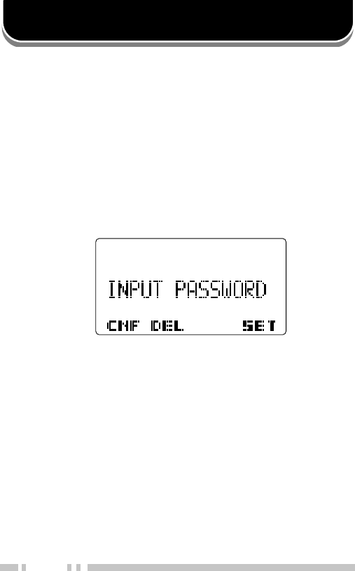
■Transceiver Password
K2 and K3 model transceivers may be password protected.
If the transciever is protected, “INPUT PASSWORD” will
appear on the display when the power is turned ON. To
unlock the transceiver, enter the correct password:
1Enter a character using the Side 2 and Side 3 keys.
•On K3 model transceivers, you can enter the password by
pressing the DTMF keys instead.
2Press the D> key (SET) to accept the character.
•This step is unnecessary when using the keypad.
3Repeat steps 1 and 2 to enter the entire password.
•Press the B key (DEL) to delete an incorrectly entered
character. Press and hold the B key to delete all
characters.
4Press the A key (CNF) to confirm the entry.
•If you enter an incorrect password, an error tone sounds
and the transceiver remains locked.
•The password can contain a maximum of 6 digits.

19
ADJUSTING THE VOLUME
Rotate the Power switch/ Volume control to adjust the
volume. Clockwise increases the volume and
counterclockwise decreases it.
SELECTING A ZONE AND CHANNEL
Select the desired zone using the selector knob or the keys
programmed as Zone Up/ Zone Down. Each zone contains
a group of channels
Select the desired channel using the selector knob or the keys
programmed as Channel Up/ Channel Down. Each channel
is programmed with settings for transmitting and receiving.
•The default setting for the selector knob is Channel Select.
K2 and K3 model transceivers may have names programmed
for zones and channels. Each name can contain up to 16
character. While selecting a zone, the zone name will appear
above the channel name for approximately 2 seconds.
•If programmed by your dealer, your transceiver will announce the
zone and channel numbers as you change them.

20
TRANSMITTING
1Select the desired zone and channel using the selector
knob and the Zone Up/ Zone Down or Channel Up/
Channel Down keys.
2Press the key programmed as Monitor or Squelch Off to
check whether or not the channel is free.
•If the channel is busy, wait until it becomes free.
3Press the PTT switch and speak into the microphone.
Release the PTT switch to receive.
•The LED indicator lights red while transmitting and green
while receiving a signal. This indicator can also be disabled
by your dealer.
•For best sound quality at the receiving station, hold the
microphone approximately 1.5 inches (3 ~ 4 cm) from your
mouth.

21
■Making Group Calls (APCO)
Channels programmed for APCO operation already have a
Group ID assigned. For these channels, you do not need
to perform steps 1 to 3, below.
Otherwise, on K2 and K3 model transceivers, if a key has
been programmed with Talkgroup, you can select a group
ID from the list to make a call to those parties.
1Press the key programmed as Talkgroup.
2Press the Side 2 and Side 3 keys or the <C and D>
keys to select a group ID/name from the list that has
been pre-entered into your transceiver.
•The target group ID/name appears on the display.
3Press the Side 1 key to set the selected group ID.
4Press and hold the PTT switch to make the call.
Speak into the transceiver as you would during a
normal transmission.
■Making Individual Calls (APCO) (K2 and K3 Models Only)
If a key has been programmed with Individual, you can
make calls to specified persons.
1Press the key programmed as Individual.
2Press the Side 2 and Side 3 keys to select a unit ID
from the list that has been pre-entered into your
transceiver.
•Alternatively, on K3 models, you can directly enter a unit
ID by using the DTMF keypad.
•The target unit ID/name appears on the display.
3Press and hold the PTT switch to make the call.
•Speak into the transceiver as you would during a normal
transmission.

22
RECEIVING
1Select the desired zone and channel using the selector
knob and the Zone Up/ Zone Down or Channel Up/
Channel Down keys. (If the Scan function has been
programmed, you can switch it on or off as desired.)
2When you hear a caller’s voice, readjust the volume as
necessary.
•If signaling has been programmed on the selected channel,
you will hear a call only if the signal tone matches the tone
set up on your transceiver.
Note: Signaling allows your transceiver to code your calls. This
will prevent you from listening to unwanted calls. It does not
make calls private, it only prevents them from being heard by
transceivers set with a different signaling code. Refer to
“SIGNALING” on page 35 for details.
■Receiving Group Calls (APCO)
When you receive a call on your group channel and the
received group ID matches the ID set up on your
transceiver, you can hear the caller’s voice. Readjust the
volume as necessary.
■Receiving Individual Calls (APCO)
When you receive an individual call, a ringing tone will
sound and on K2 and K3 model transceivers, the display
will show the caller’s ID. To respond to the call, press and
hold the PTT switch and speak into the transceiver as you
would during a normal transmission.

23
SCAN
Scan is useful for monitoring signals on the transceiver
channels. While scanning, the transceiver checks for a signal
on each channel and only stops on a channel if a signal is
present.
To begin scanning, press the key programmed as Scan.
•On K2 and K3 model transceivers, the icon appears on the
display.
•The channels included in the scan list are scanned.
•When a signal is detected on a channel, Scan pauses on that
channel. The transceiver will remain on the busy channel until
the signal is no longer present. When the signal “drops out”, the
transceiver will remain on the channel momentarily before Scan
resumes. This delay time is programmed by your dealer. If a
signal is received during the delay time, the transceiver will
remain on the same channel.
To stop scanning, press the Scan key again.
Note: In order for Scan to function, there must be at least 2 channels
added to the scanning sequence. If there are less channels than this,
Scan will not operate.
TEMPORARY CHANNEL LOCKOUT
If a key is programmed with the Scan Delete function, each
channel can be locked out of the scan sequence manually.
During scan, you can temporarily remove specific channels
from the scanning sequence by selecting them and pressing
the Scan Delete key.
•On K2 and K3 model transceivers, the icon no longer appears
on the display for that channel.
•The channel is no longer scanned. However, when scanning is
ended and restarted, the channels will reset and the channel will
again be in the scanning sequence.

24
PRIORITY SCAN
A Priority channel must be programmed in order for Priority
Scan to function.
When using a single Priority channel, the transceiver will
automatically change to the Priority channel when a call is
received on it, even if a call is being received on a normal
channel.
When using dual Priority channels, Priority channel 1 is given
precedence over Priority channel 2. So, if a call is received
on Priority channel 1 while a call is already on Priority
channel 2, the transceiver will automatically change to Priority
channel 1.
•On K2 and K3 model transceivers, “P1” appears on the display
when the displayed channel is Priority channel 1, “P2” appears
when the displayed channel is Priority channel 2, and “PP”
appears when the displayed channel is both Priority channel 1
and Priority channel 2.
SCAN REVERT
The Scan Revert channel is the channel selected when you
press the PTT switch to transmit during scan. Your dealer can
program 1 of 6 types of Scan Revert channels on your
transceiver:
•Selected: The last channel selected is assigned as the new
revert channel.
•Selected + Talkback: If the channel has been changed, the
newly selected channel is assigned as the new revert
channel. The transceiver “talks back” on the current channel.
•Priority 1/ Priority 2: If your dealer has programmed a
Priority channel (either Priority 1 or Priority 2), this channel is
the revert zone and channel.
•Priority 1 + Talkback/ Priority2 + Talkback: If your dealer
has programmed a Priority channel (either Priority 1 or
Priority 2), this channel is the revert zone and channel. The
transceiver “talks back” on the current receive channel.

25
SCAN PROGRAMMING (K2 AND K3 MODELS ONLY)
Using the key programmed with Scan Program, you are able
to reprogram your scan list.
1Press the key programmed as Scan Program.
•The icon appears on the display and blinks.
2Press the Side 2 and Side 3 keys to select the zone or
channel you will add to or remove from the scan list.
•The icon appears on the display for zones/ channels that
are added to the scan list.
•Press the A key to toggle between Zone Select and Channel
Select.
3Press the <C key to add the selected zone or channel to
the scan list or the B key to remove the selected zone or
channel from the scan list.
•The icon appears on the display when a zone/ channel is
added to the scan list, and disappears when a zone/ channel
is removed from the scan list.
If the Priority channel has been set as Operator Selectable by
your dealer, you are able to reprogram the Priority mode as
well.
1Press the key programmed as Scan Program.
•The icon appears on the display and blinks.
2Press the Side 2 and Side 3 keys to select the channel
you will set as the Priority channel.
3Press the A key.
4Press the D> key to toggle the selected channel between
Priority mode and Normal mode.
•“P1”, “P2”, or “PP” appears on the display when Priority mode
is selected.
5Press the A key again to set the new channel setting.

26
FleetSync is an Alphanumeric 2-way Paging Function, and is
a protocol owned by KENWOOD Corporation. FleetSync
enables a variety of paging functions on your transceiver,
some of which depend on dealer programming.
Note: This function is available only in Conventional FM Operation.
SELCALL (SELECTIVE CALLING)
A Selcall is a voice call to a particular station or to a group of
stations.
■Transmitting (K2 and K3 Models Only)
1Select your desired zone and channel.
2Press the key programmed as Selcall or
Selcall Status to enter Selcall mode.
3Press the Side 2 and Side 3 keys to select the ID of
the station you want to call.
•On K3 model transceivers, if Manual Dialing is enabled,
you can enter the station ID by using the DTMF keypad.
4Press the PTT switch and begin your conversation.
•Alternatively, you can press the <C key to page the
selected station, rather than making a voice call.
■Receiving
An alert tone will sound, the transceiver will automatically
enter Selcall Mode, on K2 and K3 model transceivers, the
calling station’s ID will appear when a Selcall is received.
When the call station’s ID appears on the display, you can
respond to the call by pressing the PTT switch and
speaking into the microphone.
FleetSync: ALPHANUMERIC 2-WAY PAGING FUNCTION

27
■Identification Codes
An ID code is a combination of a 3-digit Fleet number and
a 4-digit ID number. Each transceiver must have its own
Fleet and ID number.
•Enter a Fleet number (100 ~ 349) to make a group call.
•Enter an ID number (1000 ~ 4999) to make an individual call
in your fleet.
•Enter a Fleet number to make a call to all units in the selected
fleet (Fleet call).
•Enter an ID number to make a call to the selected ID in all
fleets (Supervisor call).
•Select “ALL” Fleet and “ALL” ID to make a call to all units
(Broadcast call).
Note: The ID range may be limited by programming.
STATUS MESSAGE (K2 AND K3 MODELS ONLY)
You can send and receive 2-digit Status messages which may
be decided in your talk group. Messages can contain up to 16
alphanumeric characters. Status messages range from 10 to
99 (80 ~ 99 are reserved for special messages).
A maximum of 15 received messages can be stored in the
stack memory of your transceiver. These saved messages
can be reviewed after reception. Depending on your dealer
settings, when the stack memory is full, either the oldest
message will be erased when a new message is received or
the new message will not be stored in the stack memory. The
icon lights when a message is stored in the stack memory.

28
■Transmitting
1Select your desired zone and channel.
2Press the key programmed as Status to enter Status
mode or Selcall Status to enter Selcall mode.
•When using the Status key to enter Status mode, the
station ID is fixed and cannot be selected. Skip to step 5
to continue.
3In Selcall mode, press the Side 2 and Side 3 keys to
select the ID of the station you want to call.
•If Manual Dialing is enabled, you can enter the station ID
by using the DTMF keypad.
4Press the A key to enter Status Mode.
5Press the Side 2 and Side 3 keys to select the status
ID you want to transmit.
•If Manual Dialing is enabled, you can enter a status ID by
using the DTMF keypad.
6Press the PTT switch or the <C key to initiate the
Status call.
■Receiving
The icon will flash and a calling ID or text message will
appear when a Status call is received.
Press any key to return to normal operation.

29
■Reviewing Messages in the Stack Memory
1Press and hold the key programmed as Selcall,
Status, or Selcall Status for 1 second to enter Stack
mode.
•The last received message is displayed with the message
number.
2Press the Side 2 and Side 3 keys to select the desired
message.
3Press the Side 1 key to return to normal operation.
•To delete the selected message, press the B or # key. To
confirm the deletion, press the B or # key again.
•To delete all messages, press and hold the B or # key for
1 second. To confirm the deletion, press the B or # key
again.
SHORT MESSAGES
To send a short message, you must connect the transceiver to
a PC. Ask your dealer for details.
•Short messages can contain a maximum of 48 characters.
•On K2 and K3 model transceivers, received short messages are
displayed the same as Status messages and are stored in the
same stack memory. A combined maximum of 15 Status calls
and short messages can be stored in the stack memory.
LONG MESSAGES
To send and receive long messages, you must connect the
transceiver to a PC. Ask your dealer for details.
•Long messages can contain a maximum of 4096 characters.

30
DTMF (DUAL TONE MULTI FREQUENCY) CALLS
Note: DTMF calls can be made only in Conventional FM Operation.
MAKING A DTMF CALL (K3 MODELS ONLY)
■Manual Dialing
1Press and hold the PTT switch.
2Enter the desired digits using the DTMF keypad.
•The corresponding DTMF tones sound each time you
press a key.
•If you release the PTT switch, transmit mode will end
even if the complete number has not been sent.
■Store & Send
1Enter the desired digits using the DTMF keypad.
•The digits appear on the display as you enter them.
•You can enter up to 31 digits before transmitting.
2After entering the complete number, press the PTT
switch to transmit.
Note: If you switch the power OFF before transmitting the
number, the number will be cleared.
■Keypad Auto PTT
If your dealer has activated the Keypad Auto PTT function,
simply press the keys on the keypad to make the call.
•The DTMF code will be sent automatically when you press a
key.

31
AUTODIAL (K2 AND K3 MODELS ONLY)
Autodial allows you to quickly call DTMF numbers that have
been programmed onto your transceiver.
1Press the key programmed as Autodial.
•The first entry in the Autodial list appears on the display.
2Press the Side 2 and Side 3 keys or enter the appropriate
DTMF number (01 ~ 32) to select your desired Autodial list
number.
•The stored entry appears on the display.
3Press the PTT switch to make the call.
•Alternatively, you can press the <C key to transmit the
selected DTMF number, rather than making a call.
STUN CODE
This function is used when a transceiver is stolen or lost.
When the transceiver receives a call containing a stun code,
either transmit mode will be disabled, or both receive mode
and transmit mode will be disabled. The stun code is
cancelled when the transceiver receives a call with a revive
code.

32
EMERGENCY CALLS
If your transceiver has been programmed with the Emergency
function, you can make emergency calls.
Note: Only the Auxiliary (orange) key and the PF1 (orange) key of
the optional speaker/ microphone can be programmed with the
Emergency function.
1Press and hold the key programmed as Emergency.
•Depending on the delay time programmed into your
transceiver, the length of time you must hold the Emergency
key will vary.
•When the transceiver enters Emergency mode, the
transceiver will change to the Emergency channel and begin
transmitting based on how the transceiver is set up by your
dealer. Transmit periods are also set by your dealer.
2To exit Emergency mode, press and hold the Emergency
key again.
•If the Emergency mode completes a preset number of cycles,
Emergency mode will automatically end and the transceiver
will return to the zone and channel that was in use before
Emergency mode was entered.
Note:
◆Your dealer can set the transceiver to emit a tone when
Emergency mode starts and stops
◆Your dealer can set the transceiver to emit tones and received
signals as normal or mute the speaker during Emergency
operation.

33
SCRAMBLER (FM)/ ENCRYPTION (APCO)
Note:
◆The Scrambler function can be used only in Conventional FM
Operation. Additionally, the Voice Scrambler board must be
installed before this function can be activated.
◆Ask your dealer for details concerning the Voice Scrambler board
and the Encryption DES/AES settings.
SECURE (ENCRYPTED) TRANSMISSION
Press the key programmed as Scrambler/ Encryption to
switch the transceiver to secure (encrypted) transmission.
•On K2 and K3 model transceivers, the icon appears when the
Scrambler or Encryption function is turned ON.
•Pressing the PTT switch after the Scrambler or Encryption
function has been turned ON encrypts the transmitted signal.
•Each group member must activate their respective Scrambler/
Encryption functions to descramble the received signals.
SELECTING THE SCRAMBLER CODE
1Press the key programmed as Scrambler/ Encryption
Code (K2 and K3 Models Only) or press and hold the key
programmed as Scrambler/ Encryption for 1 second, to
enter Code Selection Mode.
2Press the Side 2 and Side 3 keys or the D> and <C keys
to increase or decrease the Scrambler code.
•There are 16 available Scrambler codes (1 ~ 16).
•Each group member must use the same code in order for the
transceivers to descramble the received signals.
3Press the Side 1 key to set the new Scrambler code.

34
SELECTING THE ENCRYPTION KEY
1Press the key programmed as Scrambler/ Encryption
Code (K2 and K3 Models Only) or press and hold the key
programmed as Scrambler/ Encryption for 1 second, to
enter Key Selection Mode.
2Select the new Encryption key using the Side 2 and Side
3 keys or the <C and D> keys.
•There are 16 available Encryption keys (1 ~ 16).
•Each group member must select a key that is in each
member’s key list in order for the transceivers to descramble
the received signals.
3Press the Side 1 key to set the new Encryption key.
Note: To return the transceiver to the default Encryption key
programmed, select “PRESET”. However, if you delete the
Encryption key (see below), it will not be recovered.
DELETING THE ENCRYPTION KEY (K2 AND K3 MODELS ONLY)
1Press the key programmed as Key Delete to enter Key
Delete mode.
2Select the current Encryption key using the Side 2 and
Side 3 keys or the <C and D> keys.
3Press the B key to delete the Encryption key.
4Press the Side 1 key to exit Key Delete mode.
Note: To delete all Encryption keys (when more than one key has
been set up), select “ALL”.
PASSWORD PROTECTION (K2 AND K3 MODELS ONLY)
If the transceiver is password protected, entering an incorrect
password successively 15 times will automatically delete all
the Encryption keys.
•Turning the transceiver power OFF and the ON again will not
reset the number of attempts for entering an incorrect password.

35
SIGNALING
Note: Signaling can be used only in Conventional FM Operation.
QUIET TALK (QT)/ DIGITAL QUIET TALK (DQT)
Your dealer may have programmed QT or DQT signaling on
your transceiver channels. A QT tone/ DQT code is a
sub-audible tone/code which allows you to ignore (not hear)
calls from other parties who are using the same channel.
When a channel is set up with a QT tone or DQT code, squelch
will only open when a call containing a matching tone or code is
received. Likewise, signals that you transmit will only be heard
by parties whose QT/ DQT signaling matches your transceiver.
If a call containing a different tone or code is made on the
same channel you are using, squelch will not open and you
will not hear the call. This allows you to ignore (not hear)
these calls. Although it may seem like you have your own
private channel while using QT/ DQT, other parties can still
hear your calls if they set up their transceiver with the same
tone or code.
■OPERATOR SELECTABLE TONE (OST) (K2 AND K3 MODELS ONLY)
If a key has been programmed with Operator Selectable
Tone, you can reprogram the QT tone or DQT code on
each of your channels.
1Select your desired channel.
2Press and hold the key programmed as Operator
Selectable Tone for 1 second.
•The icon appears on the display.
3Press the Side 2 and Side 3 keys or the D> and <C
keys to select your desired tone or code from 1 to 40.
4Press the Side 1 key to save your new setting.

36
After selecting and setting up your desired tone or code,
press the Operator Selectable Tone key to activate the
OST function. Press this key again to turn the OST
function OFF.
OPTIONAL SIGNALING
Your dealer may also program several types of option
signaling for your transceiver channels.
■2-tone Signaling
2-tone Signaling opens the squelch only when your
transceiver receives a call containing matching 2 tones.
■DTMF Signaling
DTMF Signaling opens the squelch only when the
transceiver receives a call containing a matching DTMF
code.
Refert to “DTMF CALL” on page 30.
■FleetSync Signaling
Refert to “SELCALL (SELECTIVE CALLING)” on page 26.

37
VOICE OPERATED TRANSMISSION (VOX)
VOX can be activated or deactivated by your dealer. VOX
operation allows you to transmit hands-free. This feature can
only be used if you are using a supported headset.
When operating VOX, you must set a VOX Gain level. This
setting allows the transceiver to recognize sound levels. If the
microphone is too sensitive, it will begin transmitting when
there is noise in the background. If it is not sensitive enough,
it will not pick up your voice when you begin speaking. Be
sure to adjust the VOX Gain level to an appropriate sensitivity
to allow smooth transmission.
VOX GAIN LEVEL
1Connect the headset to the transceiver.
•The VOX function does not activate when a headset is not
connected to the accessory terminal of the transceiver.
2Press the key programmed as VOX.
•On K2 and K3 model transceivers, the current VOX Gain level
appears on the display.
3Press the Side 2 and Side 3 keys or the D> and <C keys
to increase or decrease the VOX Gain level.
•The VOX Gain can be adjusted from levels 1 to 10.
4While adjusting the gain level, speak into the headset
microphone as you would while under normal operation, to
test the sensitivity level.
•When the microphone recognizes a sound, the LED lights
orange. This allows you to determine a suitable level where
background noise will not activate VOX operation while
speaking into the microphone will activate it.
•The transceiver does not transmit your voice during this test
procedure.
5Press the Side 1 key to save the setting.

38
VOX OPERATION
1Connect the headset to the transceiver.
•The VOX function does not activate when a headset is not
connected to the accessory terminal of the transceiver.
2Press and hold the key programmed as VOX for
2 seconds.
•On K2 and K3 model transceivers, the icon appears on
the display.
3To transmit, simply speak into the microphone.
•The transceiver recognizes sound levels depending on the
VOX Gain level. If the microphone is too sensitive, it will
begin transmitting when there is noise in the background. If it
is not sensitive enough, it will not pick up your voice when
you begin speaking. Be sure to adjust the VOX Gain level to
an appropriate sensitivity to allow smooth transmission.
4When you finish speaking, the transceiver automatically
returns to receive mode.
•Depending on the pre-programmed delay time, it may take a
moment before returning to receive mode. The delay time is
present to ensure that the end of your conversation is not cut
off when you finish speaking.
5To turn the VOX function OFF, press and hold the VOX
key again, for 2 seconds.
Note:
◆If a speaker/ microphone is connected to the transceiver while
the VOX function is switched ON and the VOX Gain Level is
configured to a higher, more sensitive level, louder received
signals may cause the transceiver to start transmission.
◆When you operate the VOX function, you must use an optional
KHS-11BL, KHS-14, KHS-15-BH, or KHS-15-OH accessory.
39
CLOCK (K2 and K3 Models Only)
If activated by your dealer, your transceiver can track the time
with its built-in clock. The time will display momentarily when
the transceiver power is turned ON. Additionally, you can
view the clock any time by pressing the key programmed as
Clock.
Note: Removing or leaving the battery pack uncharged for extended
periods will cause the clock time to clear.
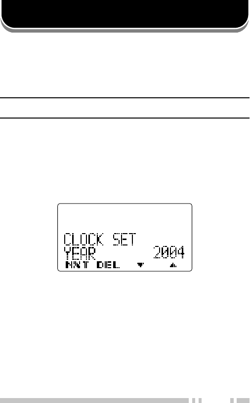
CLOCK ADJUSTMENT
To set the time:
1With the transceiver power OFF, press and hold the
Auxiliary (orange) key and the PTT switch while turning
the transceiver power ON.
•The current time setting appears.
2Release the Auxiliary (orange) key, followed by the PTT
switch.
3Press the Side 2 and Side 3 keys or the D> and <C keys
to increase or decrease the year setting.
4Press the A key to set the year.
•The transceiver cycles to the month setting.
5Repeat steps 3 and 4 to set the month, day, hour, and
minute.
6Turn the transceiver power OFF and then back ON to
return to normal operation.

40
ADVANCED OPERATIONS
Your transceiver operations vary according to the functions
that your dealer has programmed onto the transceiver keys.
Following is brief overview of the programmable functions.
Refer to those functions which have been programmed onto
your transceiver.
•Autodial (AD)
Press this key to quickly call a DTMF number that has
been pre-stored in your transceiver memory. When
viewing the Autodial list, press the <C and D> keys to
select your desired number, then press the PTT switch to
make the call. Refer to “AUTODIAL” on page 31 for details.
•Battery Status (BAT)
Press this key to view the battery power status. The
battery power status is represented by the number of
times the LED indicator flashes red. Five flashes
represents high power, 4 represents medium power, 3
represents low power, and 2 represents very low power. If
the LED flashes red only 1 time, recharge or replace your
battery pack immediately.
When the Low Battery Warning function is active {page 50}
and the battery power is low, this key will not operate.
•Call Response (RES)
Press this key to respond to an Individual call.
•Channel Down (CH▼)
Press this key to decrease the channel number. Press
and hold this key to cycle down through the channel
numbers. When the lowest channel number is reached,
the transceiver will “roll-over” to the highest channel
number and continue cycling down.
•Channel Recall (RCL)
Press this key during Scan to return to the last called zone
and channel.

41
•Channel Select
Using the selector, turn clockwise to increase the channel
number and counterclockwise to decrease the channel
number. If a channel has not been programmed, an error
tone will sound.
•Channel Up (CH▲)
Press this key to increase the channel number. Press and
hold this key to cycle up through the channel numbers.
When the highest channel number is reached, the
transceiver will “roll-over” to the lowest channel number
and continue cycling up.
•Clock (CLK)
Press this key to display the current time.
•Direct Channel 1 ~ 5 (DC1 ~ DC5)
Press one of the five Direct Channel keys to jump to a
frequently used zone and channel. The zones and
channels are programmed by your dealer.
If activated by your dealer, you can set your own Direct
Channels. First, select your desired zone and channel,
then press and hold the Direct Channel 1 ~ Direct
Channel 5 key for 3 seconds to set your selected zone
and channel as that Direct Channel.
•Display Character (CHR)
Press this key to switch the display between the zone and
channel number and the channel name (if a name has
been programmed).
•Emergency
Press and hold this key to enter Emergency mode. This
key is set up with a delay time to avoid accidentally
entering Emergency mode. The length of time you must
hold the key before entering Emergency mode depends on
the key setup. Refer to “EMERGENCY CALLS” on
page 32 for details.

42
•External Speaker (ESP)
Press this key to switch the speaker from the transceiver’s
built-in speaker to an optional external speaker. When
pressed, all messages and tones will sound from the
optional external speaker that is attached to the
transceiver, rather than from the transceiver’s built-in
speaker.
•Function (FNC)
Press this key to activate the second function of the
programmable keys. “FC” appears on the display when
this key is pressed. Press a programmable key to activate
its secondary function. (DTMF keys can also be
programmed with second functions for use with this key.)
•Home Channel (HOM)
Press this key to jump to your home zone and channel.
Your home zone and channel is programmed by your
dealer.
If activated by your dealer, you can set your own Home
Channel. First, select your desired zone and channel,
then press and hold the Home Channel key for 3 seconds
to set your selected zone and channel as the Home
Channel.
•Individual (IDV)
Press this key to activate the Individual Call function.
When activated, you must select the ID of the person you
want to call before the call can be made. Refer to “MAKING
INDIVIDUAL CALLS” on page 21 for details.
•Key Delete (KDL)
Use this key to delete any Encryption keys you have
programmed onto your transceiver. Refer to “DELETING THE
ENCRYPTION KEY” on page 34 for details.

43
•Key Lock (LCK)
Press and hold this key for 1 second to lock the
transceiver keys. When activated, the front panel keypad
and the programmable function keys (other than those
listed below) can no longer be used and “LOCKED”
appears on the display.
The following programmable functions can still be
operated: Emergency, Light, Monitor, Monitor Momentary,
Squelch Off, Squelch Off Momentary, Function, and Key
Lock. Likewise, the Selector, Concentric switch, and
Toggle switch still function normally.
Press and hold the Key Lock key again to unlock the
keys.
•Light (LIT)
Press this key to turn the display and keypad backlight on.
The backlight remains on for 5 seconds before
automatically turning off again. To manually turn the
backlight off before the timer expires, press the Light key
again.
If Auto backlight is activated by your dealer, the display
and keypad backlight will activate by pressing any key
other than the PTT switch or the Volume control. The
backlight will remain on for 5 seconds or until the Light
key is pressed.
While the backlight is on, pressing any key other than the
PTT switch, the Volume control, or the Light key will reset
the 5 second timer. The backlight will remain on for
5 seconds after the new key has been pressed.
•Low Transmit Power (LOW)
Press this key to change the output power of the
transceiver to low. When using low power, your signal
strength will not be as strong but you will save your battery
power. Use this function when you are within close range
to other members of your zone. When using low power,
the icon appears on the display.

44
Channels programmed with low power cannot be switched
to high power, but channels programmed with high power
can be switched to low power and then back to high power
by pressing this key again. When using high power, the
icon appears on the display.
•Monitor (MON)
Press this key to turn the transceiver signaling off. This
will allow you to listen to all calls that are received on your
selected channel. While monitor is activated, the icon
appears on the display. Press the Monitor key again to
turn the transceiver signaling back on.
•Monitor Momentary (MON)
Press and hold this key to momentarily turn the
transceiver signaling off. Releasing this key turns the
transceiver signaling back on. While signaling is off, you
can listen to all calls that are received on your selected
channel. While monitor is activated, the icon appears
on the display.
•None
No function has been programmed on the key.
•Operator Selectable Tone (OST)
Press and hold this key for 1 second to enter Tone
Selection mode. When activated, the icon appears on
the display. When in Tone Selection mode, use Side 2
and Side 3 keys or the the D> and <C keys to select your
desired tone from 1 to 40. Press the Side 1 key to
complete the selection.
To toggle the OST function ON and OFF, press the
Operator Selectable Tone key. Refer to “QUIET TALK
(QT)/ DIGITAL QUIET TALK (DQT)” on page 35 for details.
•OST Down (OS▼)
Press this key to decrease the Operator Selectable Tone
number of your selected channel. (This key functions
similar to the Operator Selectable Tone key.)

45
•OST Up (OS▲)
Press this key to increase the Operator Selectable Tone
number of your selected channel. (This key functions
similar to the Operator Selectable Tone key.)
•Scan (SCN)
Press this key to scan your transceiver channels for a
signal. While scanning, the icon appears on the
display. Press this key again to quit scan. Refer to
“SCAN” on page 23 for details.
•Scan Delete (DEL)
Press this key during scan operation to temporarily delete a
channel from the scanning sequence. The channel settings
are returned to normal when scan is ended. Refer to
“TEMPORARY CHANNEL LOCKOUT” on page 23 for details.
•Scan Program (SCP)
Press this key to access the scan list. You can set each
transceiver channel to be added to or removed from your
scan list. Refer to “SCAN PROGRAMMING” on page 24 for
details.
•Scrambler/ Encryption (SE)
Press this key to activate or deactivate the Scrambler/
Encryption function. When activated, the transceiver
encrypts your voice so that anybody listening to your
conversation will not be able to understand what you are
saying. Press and hold this key for 1 second, to enter
Scrambler code/ Encryption key selection mode. Refer to
“SCRAMBLER/ ENCRYPTION” on page 33 for details.
•Scrambler/ Encryption Code (SEC)
Press this key to enter Scrambler code/ Encryption key
selection mode. After entering Scrambler code/
Encryption key selection mode, press the Side 2 and Side
3 keys or the <C and D> keys to change your Scrambler
code/ Encryption key from 1 to 16, press the Side 1 key
to set the new Scrambler code/ Encryption key. Refer to
“SCRAMBLER/ ENCRYPTION” on page 33 for details.

46
•Selcall (SEL)
Press this key to enter Selcall mode. Press and hold this
key to enter Stack mode. Refer to “FleetSync:
ALPHANUMERIC 2-WAY PAGING SYSTEM” on page 26
for details.
•Selcall Status (SES)
Press this key to enter Selcall mode. Press and hold this
key to enter Stack mode. Refer to “FleetSync:
ALPHANUMERIC 2-WAY PAGING SYSTEM” on page 26
for details.
•Speaker Attenuation
Press this key (on the optional speaker/microphone) to
attenuate the received voice signals. This reduces the
strength of the speaker output to cut back any noise and
distortion present in the signal.
•Squelch Level (SQL)
Press this key to adjust the transceiver squelch level.
When adjusting the squelch level, use the Side 2 and
Side 3 keys or the D> and <C keys to increase and
decrease the squelch level.
The squelch level can be adjusted from 0 (open) to 9
(tight). The default setting is 1.
•Squelch Off (MON)
Press this key to turn the transceiver squelch off. This will
allow you to better hear weak signals on your selected
channel, as well as background noise. While squelch is off,
the icon appears on the display. Press the Squelch Off
key again to turn the transceiver squelch back on.
•Squelch Off Momentary (MON)
Press and hold this key to momentarily turn the
transceiver squelch off. Releasing this key turns the
transceiver squelch back on. While squelch is off, you can
better hear weak signals on your selected channel, as well
as background noise. While squelch is off, the icon
appears on the display.

47
•Status (STS)
Press this key to enter Status mode. Press and hold this
key to enter Stack mode. Refer to “FleetSync:
ALPHANUMERIC 2-WAY PAGING SYSTEM” on page 26
for details.
•Tactical Group (TAC)
Press and hold this key for 1 second to register the
selected channel as a Tactical Group channel. Press and
hold this key for 3 seconds to register all channels within
the current zone as Tactical Group channels.
•Talk Around (TA)
Press this key to toggle Talk Around ON and OFF. Talk
Around redirects the transceiver signals directly to other
party members rather than relaying the signals through a
repeater. When activated, the icon appears on the
display.
While using Talk Around, you free up the repeater and
communicate directly to other transceivers that are within
range. If the other party is too far away, you must
continue to use the repeater to engage in communication.
•Talkgroup (TGR)
Press this key to select the Group ID list. You can then
select the ID of the group you want to call. Refer to
“MAKING GROUP CALLS” on page 21 for details.
•Tone (TON)
Press this key to turn the transceiver audible tones off.
When active, you will no longer hear tones from the
transceiver. Press this key again to turn the audible tones
back on.
•VOX (VOX)
Press this key to adjust the external microphone VOX
level. When adjusting the VOX level, use the
Side 2 and Side 3 keys or the D> and <C keys to increase
and decrease the VOX Gain level. The VOX Gain level
can be adjusted from 1 to 10.

48
Press and hold the VOX key for 2 seconds to turn VOX
Operation mode ON or OFF. Refer to “VOICE
OPERATED TRANSMISSION (VOX)” on page 37 for
details.
•Zone Down (ZN▼)
Press this key to decrease the zone number. Press and
hold this key to cycle down through the zone numbers.
When the lowest zone number is reached, the transceiver
will “roll-over” to the highest zone number and continue
cycling down. After selecting your desired zone, the
channel display will reappear.
•Zone Select
Using the selector, turn clockwise to increase the zone
number and counterclockwise to decrease the zone
number. If a zone has not been programmed, an error
tone will sound.
•Zone Up (ZN▲)
Press this key to increase the zone number. Press and
hold this key to cycle up through the zone numbers.
When the highest zone number is reached, the transceiver
will “roll-over” to the lowest zone number and continue
cycling up. After selecting your desired zone, the channel
display will reappear.

49
BACKGROUND OPERATIONS
Your dealer can activate a variety of transceiver functions to
perform without any additional operation on your part.
TIME-OUT TIMER (TOT)
The Time-out Timer is used to prevent any caller from using a
channel for an extended period of time.
If you continuously transmit for a period of time that exceeds
the programmed time, the transceiver will stop transmitting
and an alert tone will sound. To stop the tone, release the
PTT switch. Your dealer can program the TOT time in the
range of 15 seconds to 20 minutes.
If programmed by your dealer, a pre-alert tone will sound
before the timer expires. Also, if programmed by your dealer,
you may have to wait for a short duration before you can
continue to transmit. If you press the PTT switch before the
timer has been reset, an alert tone will sound and the
transceiver will not enter transmit mode.
BATTERY SAVER
The Battery Saver function decreases the amount of power
used when a signal is not being received and no operations
are being performed (no keys are being pressed and no
switches are being turned).
While the channel is not busy and no operation is performed
for 5 seconds, Battery Saver activates. When a signal is
received or an operation is performed, Battery Saver is
disabled.

50
LOW BATTERY WARNING
Low Battery Warning alerts you when the battery needs to be
recharged.
On all transceivers, your dealer can set an alert tone to sound
and the LED indicator to blink red when the battery power is
low.
On K2 and K3 model transceivers, the battery power icon
displays the battery power remaining, as illustrated below.
High
Sufficient
Low
Very low
When the battery power is very low, recharge or replace the
battery pack.
COMPANDER
The compander is programmed only for specific (analog)
channels. If it has been programmed by your dealer,
transmitted signals are compressed before being sent and
received signals are expanded when they arrive.
•Your dealer must set the compander for both the transmit side
and the receive side in order for the compander to operate.
•On K2 and K3 model transceivers, the icon appears on the
display for when the compader activates.
This background feature allows higher clarity of signals,
avoiding excessive noise and interference. This feature is not
used on digital channels, as they are not susceptible to noise
and interference.

51
PTT ID
PTT ID is the transceiver unique ID code which sent each
time the PTT switch is pressed.
Note: PTT ID can be made only in FM Operation.
If Beginning of Transmit is set, the ID signal is transmitted
when you press the PTT switch.
If End of Transmit is set, the ID signal is transmitted when you
release the PTT switch.
If both are set, the ID signal is transmitted when you press
and release the PTT switch.
BUSY CHANNEL LOCKOUT (BCL)
If set up by your dealer, you will be unable to transmit on a
conventional channel if it is already in use. Under these
circumstances, use a different channel or wait until the
channel becomes free.
However, if BCL Override has also been programmed, you
can transmit overtop of the current signal:
1Press and hold the PTT switch.
•If the channel is already in use, a warning tone will sound.
2Release the PTT switch, then press and hold the PTT
switch again within half a second.
3Speak into the transceiver as you would during a normal
transmission.


RADIO FREQUENCY ENERGY SAFETY INFORMATION
This KENWOOD transceiver has been tested and complies with the standards listed below, in
regards to Radio Frequency (RF) energy and electromagnetic energy (EME) generated by the
transceiver.
•FCC RF exposure limits for
Occupational Use Only.
RF Exposure limits adopted by the FCC are generally
based on recommendations from the National Council on Radiation Protection and Measurements, & the
American National Standards Institute.
•FCC OET Bulletin 65 Edition 97-01 Supplement C
•American National Standards Institute (C95.1 – 1992)
•American National Standards Institute (C95.3 – 1992)
This KENWOOD transceiver generates RF EME while transmitting. RF EME (Radio Frequency Electric &
Magnetic Energy) has the potential to cause slight thermal, or heating effects to any part of your body less
than the recommended distance from this radio transmitter’s antenna. RF energy exposure is determined
primarily by the distance to and the power of the transmitting device. In general, RF exposure is
minimized when the lowest possible power is used or transmission time is kept to the minimum required
for consistent communications, and the greatest distance possible from the antenna to the body is
maintained. The transceiver has been designed for and is classified for
Occupational Use Only
.
Occupational/ controlled exposure limits are applicable to situations in which persons are exposed to RF
energy as a consequence of their employment, and such persons have been made aware of the potential
for exposure and can exercise control over their exposure. This means you can use the transceiver only if
you are aware of the potential hazards of operating a transceiver and are familiar in ways to minimize
these hazards. This transceiver is not intended for use by the general public in uncontrolled environments.
Uncontrolled environment exposure limits are applicable to situations in which the general public may be
exposed to RF energy, or in which the persons who are exposed as a consequence of their employment
may not be fully aware of the potential for exposure or cannot exercise control over their exposure.
The following list provides you with the information required to ensure that you are aware of RF
exposure and of how to operate this transceiver so that the FCC RF exposure limitations are not
exceeded.
•While transmitting (holding the PTT switch or speaking with VOX enabled), always keep the antenna and
the radio at least 3 cm (1 3/16 inches) from your body or face, as well as from any bystanders. A LED on
the top of the radio shows red when the transmitter is operating in both PTT and VOX modes.
•Do not transmit for more than 50% of the total transceiver use time; transmitting over 50% of the total use time
may exceed the limits in accordance to the FCC RF exposure requirements. Nominal transceiver operation is
5% transmission time, 5% reception time, and 90% stand-by time.
•Use only the specified antenna for this transceiver; this may be either the antenna provided with the
transceiver or another antenna authorized by KENWOOD.
Use only KENWOOD authorized accessories (antennas, battery packs, belt clips, Speaker/ Mics or
headsets etc.): When worn on the body, always place the radio in a KENWOOD recommended clip or
carrying case meant for this product. The use of other than recommended or approved body- worn
accessories may result in RF exposure levels which exceed the FCC’s occupational/ controlled
environment RF exposure limits.
To ensure that your exposure to RF EME is within the FCC limits for occupational use, you must observe
and adhere to the above points.
Electromagnetic Interference Compatibility
Electronic devices are susceptible to electromagnetic interference (EMI) if they are not adequately
shielded or designed for electromagnetic compatibility. Because this transceiver generates RF energy,
it can cause interference to such equipment.
•Turn OFF your transceiver where signs are posted to do so. Hospitals and health care facilities use
equipment that is sensitive to electromagnetic radiation.
•Turn OFF your transceiver while on board an aircraft when so instructed. Use of the transceiver must be in
accordance with airline regulations and/or crew instructions. B59-xxxx-00