Kenwood USA 409000 800MHz Digital Transceiver User Manual NX 410 K2 Users Manual
Kenwood USA Corporation 800MHz Digital Transceiver NX 410 K2 Users Manual
NX-410-K2 Users Manual

© B62-XXXX-00 (K)
09 08 07 06 05 04 03 02 01 00
NX-410
800MHz DIGITAL TRANSCEIVER
INSTRUCTION MANUAL
ÉMETTEUR-RÉCEPTEUR NUMÉRIQUE
800MHz
MODE D’EMPLOI
TRANSCEPTOR DIGITAL 800MHz
MANUAL DE INSTRUCCIONES

800MHz DIGITAL TRANSCEIVER
NX-410
INSTRUCTION MANUAL
ENGLISH
Terminal Descriptions
Universal connector
It is possible to use a resin-based cover for the Universal connector.
NO. Name Description Impedance I/O
1 SSW Ext/Int Speaker Switch Input High Impedance I
2 SP+ BTL Output + for External Speaker
O
3 SP- BTL Output - for External Speaker O
4 MSW Ext/Int MIC Switch Input High Impedance I
5 EMC External MIC Input N I
6 ME External MIC GND GND -
7 PTT External PTT Input High Impedance I
8 PF Programable Function Key Input High Impedance I
9 OPT Man Down Input High Impedance I
10 E GND GND -
11 5V 5V power supply output 5V O
12 TXD Serial Data Output CMOS O
13 RXD Serial Data Input CMOS I
14 NC Not used - -
Antenna Terminal
LPSHGDQFH
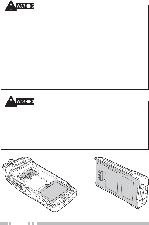
Battery Terminal
The battery terminal uses a spring plate.
The negative terminal connects to the chassis ground.
The battery is mounted on the rear side of the transceiver using a sliding
mounting method.

THANK YOU
We are grateful you have chosen Kenwood for your land
mobile radio applications.
This instruction manual covers only the basic operations of your
NEXEDGE portable radio. Ask your dealer for information on any
customized features they may have added to your radio.
NXDN™
NXDN™ is a protocol name for a new digital communications
system using 4-level FSK technology which has been
co-developed by Kenwood and Icom.
NOTICES TO THE USER
XGovernment law prohibits the operation of unlicensed radio
transmitters within the territories under government control.
X ,OOHJDORSHUDWLRQLVSXQLVKDEOHE\ÀQHDQGRULPSULVRQPHQW
X 5HIHUVHUYLFHWRTXDOLÀHGWHFKQLFLDQVRQO\
SAFETY: It is important that the operator is aware of and
understands hazards common to the operation of any
transceiver.
The AMBE+2TM voice coding Technology embodied in this product
is protected by intellectual property rights including patent rights,
copyrights and trade secrets of Digital Voice Systems, Inc. This
voice coding Technology is licensed solely for use within this
Communications Equipment. The user of this Technology is
explicitly prohibited from attempting to extract, remove, decompile,
reverse engineer, or disassemble the Object Code, or in any other
way convert the Object Code into a human-readable form. U.S.
Patent Nos. #5,870,405, #5,826,222, #5,754,974, #5,701,390,
#5,715,365, #5,649,050, #5,630,011, #5,581,656, #5,517,511,
#5,491,772, #5,247,579, #5,226,084 and #5,195,166.

i
One or more of the following statements may be applicable:
FCC WARNING
This equipment generates or uses radio frequency energy.
&KDQJHVRUPRGLÀFDWLRQVWRWKLVHTXLSPHQWPD\FDXVHKDUPIXO
LQWHUIHUHQFHXQOHVVWKHPRGLÀFDWLRQVDUHH[SUHVVO\DSSURYHGLQWKH
LQVWUXFWLRQPDQXDO7KHXVHUFRXOGORVHWKHDXWKRULW\WRRSHUDWHWKLV
HTXLSPHQWLIDQXQDXWKRUL]HGFKDQJHRUPRGLÀFDWLRQLVPDGH
INFORMATION TO THE DIGITAL DEVICE USER REQUIRED BY
THE FCC
7KLVHTXLSPHQWKDVEHHQWHVWHGDQGIRXQGWRFRPSO\ZLWKWKHOLPLWV
IRUD&ODVV%GLJLWDOGHYLFHSXUVXDQWWR3DUWRIWKH)&&5XOHV
7KHVHOLPLWVDUHGHVLJQHGWRSURYLGHUHDVRQDEOHSURWHFWLRQDJDLQVW
KDUPIXOLQWHUIHUHQFHLQDUHVLGHQWLDOLQVWDOODWLRQ
7KLVHTXLSPHQWJHQHUDWHVXVHVDQGFDQJHQHUDWHUDGLR
IUHTXHQF\HQHUJ\DQGLIQRWLQVWDOOHGDQGXVHGLQDFFRUGDQFH
ZLWKWKHLQVWUXFWLRQVPD\FDXVHKDUPIXOLQWHUIHUHQFHWRUDGLR
FRPPXQLFDWLRQV+RZHYHUWKHUHLVQRJXDUDQWHHWKDWWKH
LQWHUIHUHQFHZLOOQRWRFFXULQDSDUWLFXODULQVWDOODWLRQ,IWKLVHTXLSPHQW
GRHVFDXVHKDUPIXOLQWHUIHUHQFHWRUDGLRRUWHOHYLVLRQUHFHSWLRQ
ZKLFKFDQEHGHWHUPLQHGE\WXUQLQJWKHHTXLSPHQWRIIDQGRQWKH
user is encouraged to try to correct the interference by one or more of
WKHIROORZLQJPHDVXUHV
% 5HRULHQWRUUHORFDWHWKHUHFHLYLQJDQWHQQD
% ,QFUHDVHWKHVHSDUDWLRQEHWZHHQWKHHTXLSPHQWDQGUHFHLYHU
% &RQQHFWWKHHTXLSPHQWWRDQRXWOHWRQDFLUFXLWGLIIHUHQWIURP
WKDWWRZKLFKWKHUHFHLYHULVFRQQHFWHG
% &RQVXOWWKHGHDOHUIRUWHFKQLFDODVVLVWDQFH

ii
7KH5%5&5HF\FOHVHDOIRXQGRQKenwood
OLWKLXPLRQ/LLRQEDWWHU\SDFNVLQGLFDWHV
KenwoodҋVYROXQWDU\SDUWLFLSDWLRQLQDQLQGXVWU\
SURJUDPWRFROOHFWDQGUHF\FOH/LLRQEDWWHULHV
DIWHUWKHLURSHUDWLQJOLIHKDVH[SLUHG7KH5%5&
SURJUDPLVDQDOWHUQDWLYHWRGLVSRVLQJ/LLRQ
EDWWHULHVZLWK\RXUUHJXODUUHIXVHRULQPXQLFLSDO
ZDVWHVWUHDPVZKLFKLVLOOHJDOLQVRPHDUHDV
)RULQIRUPDWLRQRQ/LLRQEDWWHU\UHF\FOLQJLQ\RXUDUHDFDOOWROO
IUHH%$77(5<
KenwoodҋVLQYROYHPHQWLQWKLVSURJUDPLVSDUWRIRXUFRPPLWPHQW
WRSUHVHUYHRXUHQYLURQPHQWDQGFRQVHUYHRXUQDWXUDOUHVRXUFHV
7KH5%5&5HF\FOHVHDOIRXQGRQKenwood
QLFNHOFDGPLXP1L&GEDWWHU\SDFNVLQGLFDWHV
KenwoodҋVYROXQWDU\SDUWLFLSDWLRQLQDQLQGXVWU\
SURJUDPWRFROOHFWDQGUHF\FOH1L&GEDWWHULHV
DIWHUWKHLURSHUDWLQJOLIHKDVH[SLUHG7KH5%5&
SURJUDPLVDQDOWHUQDWLYHWRGLVSRVLQJ1L&G
EDWWHULHVZLWK\RXUUHJXODUUHIXVHRULQPXQLFLSDO
ZDVWHVWUHDPVZKLFKLVLOOHJDOLQVRPHDUHDV
)RULQIRUPDWLRQRQ1L&GEDWWHU\UHF\FOLQJLQ\RXUDUHDFDOOWROO
IUHH%$77(5<
KenwoodҋVLQYROYHPHQWLQWKLVSURJUDPLVSDUWRIRXUFRPPLWPHQW
WRSUHVHUYHRXUHQYLURQPHQWDQGFRQVHUYHRXUQDWXUDOUHVRXUFHV
7KH5%5&5HF\FOHVHDOIRXQGRQKenwoodQLFNHO
PHWDOK\GULGH1L0+EDWWHU\SDFNVLQGLFDWHV
KenwoodҋVYROXQWDU\SDUWLFLSDWLRQLQDQLQGXVWU\
SURJUDPWRFROOHFWDQGUHF\FOH1L0+EDWWHULHV
DIWHUWKHLURSHUDWLQJOLIHKDVH[SLUHG7KH5%5&
SURJUDPLVDQDOWHUQDWLYHWRGLVSRVLQJ1L0+
EDWWHULHVZLWK\RXUUHJXODUUHIXVHRULQPXQLFLSDO
ZDVWHVWUHDPVZKLFKLVLOOHJDOLQVRPHDUHDV
)RULQIRUPDWLRQRQ1L0+EDWWHU\UHF\FOLQJLQ\RXUDUHDFDOOWROO
IUHH%$77(5<
KenwoodҋVLQYROYHPHQWLQWKLVSURJUDPLVSDUWRIRXUFRPPLWPHQWWR
SUHVHUYHRXUHQYLURQPHQWDQGFRQVHUYHRXUQDWXUDOUHVRXUFHV

iii
PRECAUTIONS
'RQRWFKDUJHWKHWUDQVFHLYHUDQGEDWWHU\SDFNZKHQWKH\DUHZHW
(QVXUHWKDWWKHUHDUHQRPHWDOOLFLWHPVORFDWHGEHWZHHQWKH
WUDQVFHLYHUDQGWKHEDWWHU\SDFN
'RQRWXVHRSWLRQVQRWVSHFLÀHGE\Kenwood.
,IWKHGLHFDVWFKDVVLVRURWKHUWUDQVFHLYHUSDUWLVGDPDJHGGRQRW
touch the damaged parts.
,IDKHDGVHWRUKHDGSKRQHLVFRQQHFWHGWRWKHWUDQVFHLYHUUHGXFH
WKHWUDQVFHLYHUYROXPH3D\DWWHQWLRQWRWKHYROXPHOHYHOZKHQ
WXUQLQJWKHVTXHOFKRII
'RQRWSODFHWKHPLFURSKRQHFDEOHDURXQG\RXUQHFNZKLOHQHDU
PDFKLQHU\WKDWPD\FDWFKWKHFDEOH
'RQRWSODFHWKHWUDQVFHLYHURQXQVWDEOHVXUIDFHV
(QVXUHWKDWWKHHQGRIWKHDQWHQQDGRHVQRWWRXFK\RXUH\HV
:KHQWKHWUDQVFHLYHULVXVHGIRUWUDQVPLVVLRQIRUPDQ\KRXUVWKH
UDGLDWRUDQGFKDVVLVZLOOEHFRPHKRW'RQRWWRXFKWKHVHORFDWLRQV
ZKHQUHSODFLQJWKHEDWWHU\SDFN
$OZD\VVZLWFKWKHWUDQVFHLYHUSRZHURIIEHIRUHLQVWDOOLQJRSWLRQDO
accessories.
7KHFKDUJHULVWKHGHYLFHWKDWGLVFRQQHFWVWKHXQLWIURPWKH$&
PDLQVOLQH7KH$&SOXJVKRXOGEHUHDGLO\DFFHVVLEOH
LY
Turn the transceiver power off in the following locations:
1HDUH[SORVLYHVRUEODVWLQJVLWHV
,QDLUFUDIWV$Q\XVHRIWKHWUDQVFHLYHUPXVWIROORZWKH
LQVWUXFWLRQVDQGUHJXODWLRQVSURYLGHGE\WKHDLUOLQHFUHZ
:KHUHUHVWULFWLRQVRUZDUQLQJVDUHSRVWHGUHJDUGLQJWKHXVHRI
UDGLRGHYLFHVLQFOXGLQJEXWQRWOLPLWHGWRPHGLFDOIDFLOLWLHV
1HDUSHUVRQVZHDULQJSDFHPDNHUV
Turn the transceiver power off in the following locations,
unless the model is specifically qualified for such use
(Intrinsically Safe such as approved by Factory Mutual, CSA):
,QH[SORVLYHDWPRVSKHUHVLQÁDPPDEOHJDVGXVWSDUWLFOHV
PHWDOOLFSRZGHUVJUDLQSRZGHUVHWF
:KLOHWDNLQJRQIXHORUZKLOHSDUNHGDWJDVROLQHVHUYLFHVWDWLRQV
7KHRUDQJHVHDORQWKHUHYHUVHVLGHRIWKHWUDQVFHLYHULV
LPSRUWDQWZLWKUHVSHFWWRWKHZDWHUSURRIHIÀFLHQF\RIWKH
WUDQVFHLYHU'RQRWSODFHVWLFNHUVRURWKHUPDWHULDOVRQRU
DURXQGWKHVHDOVKRZQLQWKHÀJXUHRURQWKHUHYHUVHVLGHRI
WKHEDWWHU\SDFN'RLQJVRZLOOLPSDLUWKHZDWHUSURRIHIÀFLHQF\
RIWKHWUDQVFHLYHUDQGPD\FDXVHLWWREUHDNGRZQ$GGLWLRQDOO\
LQRUGHUWRSUHYHQWGDPDJHWRWKHVHDOGRQRWDOORZLWWRFRPH
LQFRQWDFWZLWKIRUHLJQPDWHULDOV

Y
'RQRWGLVDVVHPEOHRUPRGLI\WKHWUDQVFHLYHUIRUDQ\UHDVRQ
'RQRWSODFHWKHWUDQVFHLYHURQRUQHDUDLUEDJHTXLSPHQWZKLOH
WKHYHKLFOHLVUXQQLQJ:KHQWKHDLUEDJLQÁDWHVWKHWUDQVFHLYHU
PD\EHHMHFWHGDQGVWULNHWKHGULYHURUSDVVHQJHUV
'RQRWWUDQVPLWZKLOHWRXFKLQJWKHDQWHQQDWHUPLQDORULI
DQ\PHWDOOLFSDUWVDUHH[SRVHGIURPWKHDQWHQQDFRYHULQJ
7UDQVPLWWLQJDWVXFKDWLPHPD\UHVXOWLQDKLJKIUHTXHQF\EXUQ
,IDQDEQRUPDORGRURUVPRNHLVGHWHFWHGFRPLQJIURPWKH
WUDQVFHLYHUVZLWFKWKHWUDQVFHLYHUSRZHURIILPPHGLDWHO\
UHPRYHWKHEDWWHU\SDFNIURPWKHWUDQVFHLYHUDQGFRQWDFW\RXU
KenwoodGHDOHU
8VHRIWKHWUDQVFHLYHUZKLOH\RXDUHGULYLQJPD\EHDJDLQVW
WUDIÀFODZV3OHDVHFKHFNDQGREVHUYHWKHYHKLFOHUHJXODWLRQV
in your area.
'RQRWH[SRVHWKHWUDQVFHLYHUWRH[WUHPHO\KRWRUFROG
conditions.
'RQRWFDUU\WKHEDWWHU\SDFNRUEDWWHU\FDVHZLWKPHWDO
REMHFWVDVWKH\PD\VKRUWWKHEDWWHU\WHUPLQDOV

YL
INFORMATION CONCERNING THE BATTERY PACK
7KHEDWWHU\SDFNLQFOXGHVÁDPPDEOHREMHFWVVXFKDVRUJDQLFVROYHQW
0LVKDQGOLQJPD\FDXVHWKHEDWWHU\WRUXSWXUHSURGXFLQJÁDPHVRU
H[WUHPHKHDWGHWHULRUDWHRUFDXVHRWKHUIRUPVRIGDPDJHWRWKH
EDWWHU\3OHDVHREVHUYHWKHIROORZLQJSURKLELWLYHPDWWHUV
•Do not disassemble or reconstruct battery!
7KHEDWWHU\SDFNKDVDVDIHW\IXQFWLRQDQGSURWHFWLRQFLUFXLWWR
DYRLGGDQJHU,IWKH\VXIIHUVHULRXVGDPDJHWKHEDWWHU\PD\
JHQHUDWHKHDWRUVPRNHUXSWXUHRUEXUVWLQWRÁDPH
•Do not short-circuit the battery!
'RQRWMRLQWKHDQG²WHUPLQDOVXVLQJDQ\IRUPRIPHWDOVXFK
DVDSDSHUFOLSRUZLUH'RQRWFDUU\RUVWRUHWKHEDWWHU\SDFN
LQFRQWDLQHUVKROGLQJPHWDOREMHFWVVXFKDVZLUHVFKDLQ
QHFNODFHRUKDLUSLQV,IWKHEDWWHU\SDFNLVVKRUWFLUFXLWHG
H[FHVVLYHFXUUHQWZLOOÁRZDQGWKHEDWWHU\PD\JHQHUDWHKHDW
RUVPRNHUXSWXUHRUEXUVWLQWRÁDPH,WZLOODOVRFDXVHPHWDO
objects to heat up.
•Do not incinerate or apply heat to the battery!
,IWKHLQVXODWRULVPHOWHGWKHJDVUHOHDVHYHQWRUVDIHW\IXQFWLRQ
LVGDPDJHGRUWKHHOHFWURO\WHLVLJQLWHGWKHEDWWHU\PD\
JHQHUDWHKHDWRUVPRNHUXSWXUHRUEXUVWLQWRÁDPH
•Do not use or leave the battery near fires, stoves, or other
heat generators (areas reaching over 80°C/ 176°F)!
,IWKHSRO\PHUVHSDUDWRULVPHOWHGGXHWRKLJKWHPSHUDWXUH
DQLQWHUQDOVKRUWFLUFXLWPD\RFFXULQWKHLQGLYLGXDOFHOOVDQG
WKHEDWWHU\PD\JHQHUDWHKHDWRUVPRNHUXSWXUHRUEXUVWLQWR
ÁDPH
•Avoid immersing the battery in water or getting it wet by
other means!
,IWKHEDWWHU\EHFRPHVZHWZLSHLWRIIZLWKDGU\WRZHOEHIRUH
XVH,IWKHEDWWHU\ҋVSURWHFWLRQFLUFXLWLVGDPDJHGWKHEDWWHU\
PD\FKDUJHDWH[WUHPHFXUUHQWRUYROWDJHDQGDQDEQRUPDO
FKHPLFDOUHDFWLRQPD\RFFXU7KHEDWWHU\PD\JHQHUDWHKHDWRU
VPRNHUXSWXUHRUEXUVWLQWRÁDPH

YLL
•Do not charge the battery near fires or under direct
sunlight!
,IWKHEDWWHU\ҋVSURWHFWLRQFLUFXLWLVGDPDJHGWKHEDWWHU\PD\
FKDUJHDWH[WUHPHFXUUHQWRUYROWDJHDQGDQDEQRUPDO
FKHPLFDOUHDFWLRQPD\RFFXU7KHEDWWHU\PD\JHQHUDWHKHDWRU
VPRNHUXSWXUHRUEXUVWLQWRÁDPH
•Use only the specified charger and observe charging
requirements!
,IWKHEDWWHU\LVFKDUJHGLQXQVSHFLÀHGFRQGLWLRQVXQGHUKLJK
WHPSHUDWXUHRYHUWKHUHJXODWHGYDOXHH[FHVVLYHKLJKYROWDJH
RUFXUUHQWRYHUUHJXODWHGYDOXHRUZLWKDUHPRGHOOHGFKDUJHU
LWPD\RYHUFKDUJHRUDQDEQRUPDOFKHPLFDOUHDFWLRQPD\RFFXU
7KHEDWWHU\PD\JHQHUDWHKHDWRUVPRNHUXSWXUHRUEXUVWLQWR
ÁDPH
•Do not pierce the battery with any object, strike it with an
instrument, or step on it!
7KLVPD\EUHDNRUGHIRUPWKHEDWWHU\FDXVLQJDVKRUWFLUFXLW
7KHEDWWHU\PD\JHQHUDWHKHDWRUVPRNHUXSWXUHRUEXUVWLQWR
ÁDPH
•Do not jar or throw the battery!
$QLPSDFWPD\FDXVHWKHEDWWHU\WROHDNJHQHUDWHKHDW
RUVPRNHUXSWXUHDQGRUEXUVWLQWRÁDPH,IWKHEDWWHU\ҋV
SURWHFWLRQFLUFXLWLVGDPDJHGWKHEDWWHU\PD\FKDUJHDWDQ
DEQRUPDOFXUUHQWRUYROWDJHDQGDQDEQRUPDOFKHPLFDO
reaction may occur.
•Do not use the battery pack if it is damaged in any way!
7KHEDWWHU\PD\JHQHUDWHKHDWRUVPRNHUXSWXUHRUEXUVWLQWR
ÁDPH
•Do not solder directly onto the battery!
,IWKHLQVXODWRULVPHOWHGRUWKHJDVUHOHDVHYHQWRUVDIHW\
IXQFWLRQLVGDPDJHGWKHEDWWHU\PD\JHQHUDWHKHDWRUVPRNH
UXSWXUHRUEXUVWLQWRÁDPH
•Do not reverse the battery polarity (and terminals)!
:KHQFKDUJLQJDUHYHUVHGEDWWHU\DQDEQRUPDOFKHPLFDO
UHDFWLRQPD\RFFXU,QVRPHFDVHVDQXQH[SHFWHGODUJH
DPRXQWRIFXUUHQWPD\ÁRZXSRQGLVFKDUJLQJ7KHEDWWHU\PD\
JHQHUDWHKHDWRUVPRNHUXSWXUHRUEXUVWLQWRÁDPH

YLLL
•Do not charge the battery for longer than the specified
time!
,IWKHEDWWHU\SDFNKDVQRWÀQLVKHGFKDUJLQJHYHQDIWHUWKH
UHJXODWHGWLPHKDVSDVVHGVWRSLW7KHEDWWHU\PD\JHQHUDWH
KHDWRUVPRNHUXSWXUHRUEXUVWLQWRÁDPH
•Do not place the battery pack into a microwave or high
pressure container!
7KHEDWWHU\PD\JHQHUDWHKHDWRUVPRNHUXSWXUHRUEXUVWLQWR
ÁDPH
•Keep ruptured and leaking battery packs away from fire!
,IWKHEDWWHU\SDFNLVOHDNLQJRUWKHEDWWHU\HPLWVDEDGRGRU
LPPHGLDWHO\UHPRYHLWIURPÁDPPDEOHDUHDV(OHFWURO\WH
OHDNLQJIURPEDWWHU\FDQHDVLO\FDWFKRQÀUHDQGPD\FDXVHWKH
EDWWHU\WRJHQHUDWHVPRNHRUEXUVWLQWRÁDPH
•Do not use an abnormal battery!
,IWKHEDWWHU\SDFNHPLWVDEDGRGRUDSSHDUVWRKDYHGLIIHUHQW
FRORULQJLVGHIRUPHGRUVHHPVDEQRUPDOIRUDQ\RWKHUUHDVRQ
UHPRYHLWIURPWKHFKDUJHURURSHUDWLQJHTXLSPHQWDQGGRQRW
XVHLW7KHEDWWHU\PD\JHQHUDWHKHDWRUVPRNHUXSWXUHRU
EXUVWLQWRÁDPH
•Do not reverse-charge or reverse-connect the battery!
7KHEDWWHU\SDFNKDVSRVLWLYHDQGQHJDWLYHSROHV,IWKHEDWWHU\
SDFNGRHVQRWVPRRWKO\FRQQHFWZLWKDFKDUJHURURSHUDWLQJ
HTXLSPHQWGRQRWIRUFHLWFKHFNWKHSRODULW\RIWKHEDWWHU\,I
WKHEDWWHU\SDFNLVUHYHUVHFRQQHFWHGWRWKHFKDUJHULWZLOOEH
UHYHUVHFKDUJHGDQGDQDEQRUPDOFKHPLFDOUHDFWLRQPD\RFFXU
7KHEDWWHU\PD\JHQHUDWHKHDWRUVPRNHUXSWXUHRUEXUVWLQWR
ÁDPH
•Do not touch a ruptured and leaking battery!
,IWKHHOHFWURO\WHOLTXLGIURPWKHEDWWHU\JHWVLQWR\RXUH\HV
ZDVK\RXUH\HVRXWZLWKIUHVKZDWHUDVVRRQDVSRVVLEOH
ZLWKRXWUXEELQJ\RXUH\HV*RWRWKHKRVSLWDOLPPHGLDWHO\,I
OHIWXQWUHDWHGLWPD\FDXVHH\HSUREOHPV

L[
CONTENTS
813$&.,1*$1'&+(&.,1*(48,30(17...............................
SUPPLIED ACCESSORIES ...............................................................1
35(3$5$7,21 ............................................................................
INSTALLING/REMOVING THE (OPTIONAL) BATTERY PACK ....................2
INSTALLING THE (OPTIONAL) ANTENNA.............................................2
INSTALLING THE BELT CLIP ............................................................3
INSTALLING THE CAP OVER THE UNIVERSAL CONNECTOR ...................3
INSTALLING THE (OPTIONAL) SPEAKER/MICROPHONE OR HEADSET ......3
*(77,1*$&48$,17(' .............................................................4
DISPLAY .....................................................................................6
352*5$00$%/()81&7,216..................................................
%$6,&23(5$7,216 ...................................................................9
SWITCHING POWER ON/ OFF ......................................................9
ADJUSTING THE VOLUME...............................................................9
SELECTING A ZONE AND CHANNEL/GROUP ID................................10
TRANSMITTING...........................................................................10
RECEIVING................................................................................11
0(1802'( ..............................................................................
MENU ACCESS ..........................................................................12
MENU CONFIGURATION ...............................................................12
CHARACTER ENTRY ...................................................................14
6&$1...........................................................................................
TEMPORARY CHANNEL LOCKOUT ..................................................15
PRIORITY SCAN.........................................................................15
SCAN REVERT ..........................................................................16
SCAN DELETE/ADD....................................................................16
PRIORITY-CHANNEL SELECT ........................................................16
)OHHW6ync$/3+$180(5,&:$<3$*,1*)81&7,21.......
SELCALL (SELECTIVE CALLING)....................................................17
STATUS MESSAGE......................................................................18
SHORT/LONG MESSAGES............................................................19
GPS REPORT ..........................................................................19

[
$'9$1&('23(5$7,216 ........................................................
DTMF (DUAL TONE MULTI FREQUENCY)CALLS ............................20
TRUNKING CALLS (ANALOG)........................................................21
EMERGENCY CALLS ...................................................................22
SCRAMBLER..............................................................................22
SIGNALING................................................................................23
VOICE OPERATED TRANSMISSION (VOX) ......................................24
%$&.*5281'23(5$7,216 ..................................................
CLOCK.....................................................................................26
VIBRATOR.................................................................................26
TIME-OUT TIMER (TOT).............................................................26
BATTERY SAVER ........................................................................27
KEY LOCK ................................................................................27
LOW BATTERY WARNING.............................................................27
SIGNAL STRENGTH INDICATOR......................................................27
COMPANDER .............................................................................28
BUSY CHANNEL LOCKOUT (BCL).................................................28
CONTROL CHANNEL HUNT ..........................................................28
PTT ID...................................................................................28
9*6237,21$/92,&(*8,'(6725$*(81,7...............
VOICE RECORDER .....................................................................29
VOICE GUIDE............................................................................30

1
813$&.,1*$1'&+(&.,1*(48,30(17
Note: These unpacking instructions are for use by your Kenwood
dealer, an authorized Kenwood service facility, or the factory.
Carefully unpack the transceiver. We recommend that you
identify the items listed in the following list before discarding
WKHSDFNLQJPDWHULDO,IDQ\LWHPVDUHPLVVLQJRUGDPDJHGÀOH
a claim with the carrier immediately.
6833/,('$&&(6625,(6
Belt clip . ...............................................1
• Screws for belt clip (3 x 8 mm) ........................... 2
Universal connector cap . ..................................1
• Dressing screw (preassembled) ..........................1
• Packing (preassembled) ................................1
Instruction manual ........................................1
2
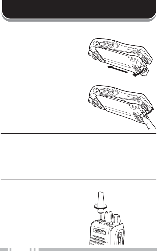
35(3$5$7,21
,167$//,1*5(029,1*7+(237,21$/%$77(5<3$&.
1Match the guides of the
battery pack with the grooves
on the upper rear of the
WUDQVFHLYHUWKHQÀUPO\SUHVV
the battery pack in place.
2Lock the safety catch to
prevent accidentally releasing
the battery pack.
3To remove the battery pack,
lift the safety catch, press the
release latch, then pull the
battery pack away from the
transceiver.
Note:
XFor battery pack charging procedures and useage, refer to the
battery charger Instruction Manual.
X Before charging a battery pack that is attached to the
WUDQVFHLYHUHQVXUHWKDWWKHVDIHW\FDWFKLVÀUPO\FORVHG
XWhile operating the transceiver using a Li-ion battery pack in
areas with an ambient temperature of –10°C/ +14°F and lower,
operating time may be shortened.
,167$//,1*7+(237,21$/$17(11$
Screw the antenna into the
connector on the top of the
transceiver by holding the
antenna at its base and turning
it clockwise until secure.
1
2
3
Optional
antenna
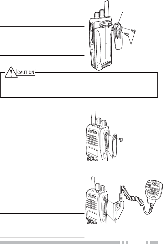
3
Do not use glue which is designed to prevent screw loosening when
installing the belt clip. Acrylic ester, which is contained in these
glues, may crack the transceiver’s back panel.
,167$//,1*7+(&$329(57+(81,9(56$/&211(&725
,167$//,1*7+(%(/7&/,3
Attach the belt clip using the
supplied 3 x 8 mm screws.
Note: If the belt clip is not
installed, its mounting location
may get hot during continuous
transmission or when left sitting in
a hot environment.
Insert the cap into place over the
universal connector and secure
it in place using the attached
screw.
,167$//,1*7+(237,21$/63($.(50,&523+21(25+($'6(7
1Insert the guide of the
speaker/ microphone or
headset connector into place
over the universal connector.
2Secure the connector in place
using the attached screw.
Note: When not using an optional
speaker/ microphone or headset,
install the cap over the universal
connector.
3 x 8 mm screws
Belt clip
MIC
Optional
speaker/ microphone
MIC
Universal
connector cap
4
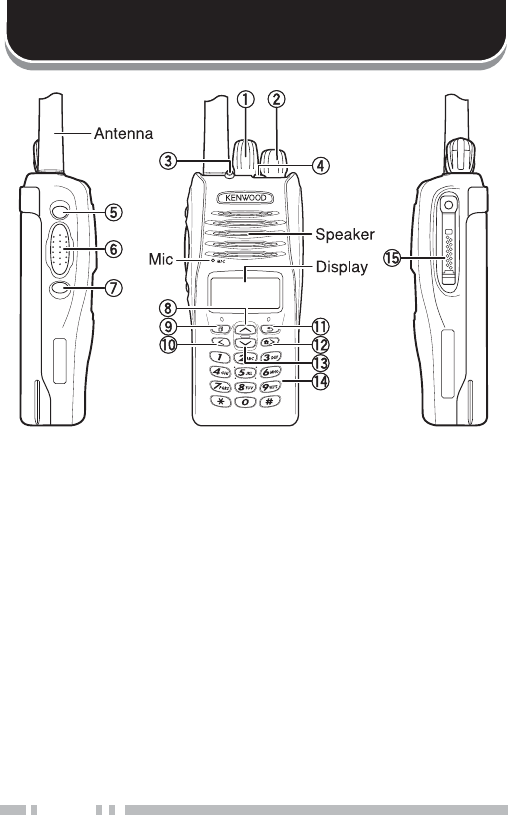
*(77,1*$&48$,17('
① Selector knob
Rotate to select a zone or channel/group ID (default).
② Power switch/ Volume control
Rotate to turn the transceiver ON/OFF and to adjust the
volume.
③ Transmit/ Receive/ Battery low indicator
If enabled by your dealer, lights red while transmitting,
green while receiving a call (Conventional channels only),
and orange when receiving an optional signaling call
(DTMF signaling, etc.). Blinks red when the battery power is
low while transmitting.
④ Auxiliary key
Press to activate its programmable function {page 7}.

5
⑤ Side 1 key
Press to activate its programmable function {page 7}. The
default is Squelch Off Momentary.
⑥ PTT (Push-To-Talk) switch
Press and hold this switch, then speak into the microphone
to call a station.
⑦ Side 2 key
Press to activate its programmable function {page 7}. The
default is Backlight.
⑧ key
Press to activate its programmable function {page 7}. The
default is Zone Up.
⑨key
Press to activate its programmable function {page 7}. The
default is Menu.
⑩key
Press to activate its programmable function {page 7}.
⑪key
Press to activate its programmable function {page 7}.
⑫key
Press to activate its programmable function {page 7}.
⑬key
Press to activate its programmable function {page 7}. The
default is Zone Down.
⑭ Keypad
Press these keys to send DTMF tones. These keys can
also be programmed with secondary functions {page 7} if a
programmable function key is programmed as “Function”.
⑮Universal connector
Connect a speaker/ microphone or headset here {page 3}.
Otherwise, keep the supplied cap in place.
6
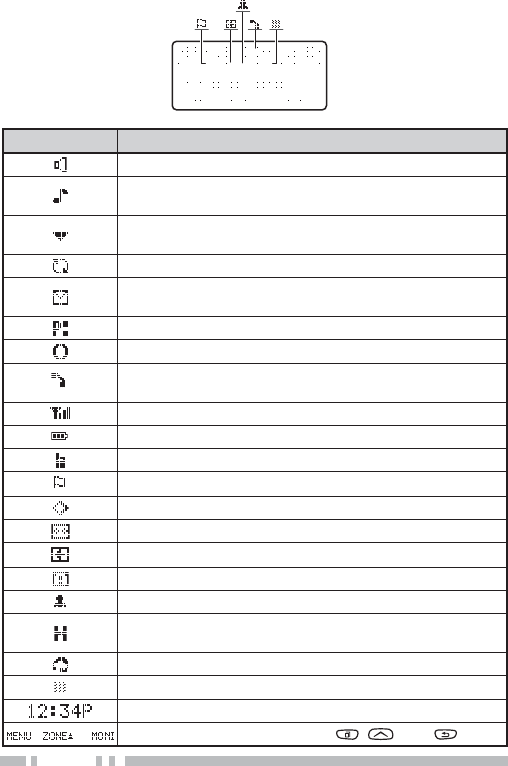
',63/$<
Indicator Description
Monitor or Squelch Off is activated.
Blinks when an incoming call matches your Optional
Signaling.
The current zone (left icon) or CH/GID (right icon) is
added to scan.
Scan is in progress. Blinks while scan is paused.
A message is stored in memory. Blinks when a new
message has arrived.
The current channel is a Priority channel.
Operator Selectable Tone (OST) is activated.
A Telephone ID call is being received. Blinks during
Auto Telephone search.
Signal strength indicator {page 27}.
Battery power indicator {page 27}.
Talk Around is activated.
Site Lock is activated.
Scrambler/ Encryption is activated.
Auto Recording on the VGS-1 option is activated.
Auto Reply Message is activated.
The auxiliary function is activated.
Lone Worker is activated.
The channel is using high transmit power. “L”
appears when using low transmit power.
VOX is activated.
The vibrator is activated. Blinks when inhibited.
Displays the time.
Displays the key functions for , , and .

7
352*5$00$%/()81&7,216
Following is a list of available programmable functions. Please
contact your dealer for further details on those functions which
have been programmed on your transceiver.
• Auto Reply Message 2
• Auto Telephone 3
• Autodial 4
• Autodial Programming 4
• AUX
• Backlight
• Broadcast 5
• Call 1 ~ 6
• CH/GID Down
• Channel Entry
• CH/GID Recall
• CH/GID Up
• Clock
• Clock Adjustment
• CW Message 7
• Direct CH/GID 1 ~ 5
• Direct CH/GID Select 1 ~ 5
• Display Format
• Emergency 8
• Fixed Volume
• Forced Search 5
• Function
• GPS Position Display
• Group (NXDN) 7
• Group + SDM (NXDN) 9
• Group + Status (NXDN) 9
• Home CH/GID
• Home CH/GID Select
• Individual (NXDN) 9
• Individual + SDM (NXDN) 9
• Individual + Status (NXDN) 9
• Key Lock
• Lone Worker
• Low Transmit Power
• Maintenance
• Menu
• Monitor 4
• Monitor Momentary 4
• OST 1
• Playback 2
• Priority-channel Select 11
• Scan
• Scan Delete/Add
• Scrambler/Encryption
• Scramber/Encryption Code 9
• SDM (FleetSync/NXDN)
• Selcall (FleetSync) 10
• Selcall + SDM (FleetSync) 10
•
Selcall + Status (FleetSync)
10
• Send the GPS data
• Site Down 5
• Site Lock 5
• Site Up 5
• Site Up/Down 5, 6
• Speaker Attenuation 12
• Squelch Level 1
• Squelch Off 1
• Squelch Off Momentary 1
• Stack
• Status (FleetSync/ NXDN)
• Talk Around 4
• Telephone Disconnect 3
• Transceiver Password
• Vibrator

8
• Voice Memo 2
• VOX 11
• Zone Delete/Add
• Zone Down
• Zone Up
1Available only for Analog Conventional operation.
2Available only if the VGS-1 optional board has been installed.
3Available only for Analog Trunking operation.
4Available only for Analog Conventional, Analog Trunking, and NXDN
Conventional operation.
5Available only for NXDN Trunking operation.
6Can be programmed only on the Selector knob.
7Available only for NXDN Conventional operation.
8Can be programmed only on the Auxiliary key and the optional
speaker/ microphone PF1 (orange) key.
9Available only for NXDN Conventional and NXDN Trunking operation.
10Available only for Analog Conventional and Analog Trunking
operation.
11 Available only for Analog Conventional and NXDN Conventional
operation.
12Can be programmed only on the microphone programmable function
keys.

9
%$6,&23(5$7,216
6:,7&+,1*32:(5212))
Turn the Power switch/ Volume control clockwise to switch the
transceiver ON.
Turn the Power switch/ Volume control counterclockwise fully
to switch the transceiver OFF.
Q 7UDQVFHLYHU3DVVZRUG
If the transceiver is password protected, “PASSWORD” will
appear on the display when the power is turned ON. To
unlock the transceiver, enter the password:
1Select a character using the DTMF keypad.
• Press or # to delete a character. Press and hold or
# to delete all characters.
2Press or WRFRQÀUPWKHHQWU\
• If you enter an incorrect password, an error tone sounds
and the transceiver remains locked.
• The password can contain a maximum of 6 digits.
$'-867,1*7+(92/80(
Rotate the Power switch/ Volume control to adjust the volume.
Clockwise increases the volume and counterclockwise
decreases it.

10
6(/(&7,1*$=21($1'&+$11(/*5283,'
Select the desired zone using / (default). Each zone
contains a group of channels.
Select the desired channel/group ID using the Selector knob
(default). Each channel/group ID is programmed with settings
for transmitting and receiving.
• You can toggle the display between the zone and channel/group
ID names and number by pressing the key programmed as Display
Format, or by accessing the Menu {page 12}.
Note: If the default settings for / and the Selector knob
have been changed, use the appropriate keys to select the zone
and channel/group ID.
75$160,77,1*
1Select the desired zone and channel/group ID.
2Press the key programmed as Monitor or Squelch Off to
check whether or not the channel is free.
• If the channel is busy, wait until it becomes free.
3Press the PTT switch and speak into the microphone.
Release the PTT switch to receive.
• For best sound quality, hold the transceiver approximately
1.5 inches (3 ~ 4 cm) from your mouth.
Q 0DNLQJ*URXS&DOOV'LJLWDO
If a key has been programmed with Group or Group +
Status, you can select a group ID from the list to make a
call to those parties on a Conventional channel.
To select a group ID:
1
Press the key programmed as Group or Group + Status.
2Press / to select a group ID/name from the list.
3Press and hold the PTT switch to make the call.
• Speak into the transceiver as you would during a normal
transmission.

11
Q 0DNLQJ,QGLYLGXDO&DOOV'LJLWDO
If a key has been programmed with Individual or
Individual + Status\RXFDQPDNHFDOOVWRVSHFLÀF
persons.
1Press the key programmed as Individual or
Individual + Status.
2Press
/
to select a unit ID from the list.
• You can enter the unit ID directly, using the DMF keypad.
3Press and hold the PTT switch to make the call.
• Speak into the transceiver as you would during a normal
transmission.
5(&(,9,1*
Select the desired zone and channel. If signaling has been
programmed on the selected channel, you will hear a call only
if the received signal matches your transceiver settings.
Note: Signaling allows your transceiver to code your calls. This will
prevent you from listening to unwanted calls. Refer to “SIGNALING”
on page 23 for details.
Q 5HFHLYLQJ*URXS&DOOV'LJLWDO
When you receive a group call on a Conventional channel
and the received group ID matches the ID set up on your
transceiver, you can hear the caller’s voice.
When you receive a group call on a Trunking channel, the
transceiver automatically switches to the communications
channel to receive the call.
Q 5HFHLYLQJ,QGLYLGXDO&DOOV'LJLWDO
When you receive an individual call, a ringing tone will
sound and the caller’s ID will appear on the display. To
respond to the call, press and hold the PTT switch and
speak into the transceiver as you would during a normal
transmission.
12
0(1802'(
0DQ\IXQFWLRQVRQWKLVWUDQVFHLYHUDUHVHOHFWHGRUFRQÀJXUHG
through the Menu instead of physical controls. Once you
become familiar with the Menu system, you will appreciate the
versatility it offers.
0(18$&&(66
1Press the key programmed as Menu.
• The category list is shown.
• When there is only 1 category, the function list is shown
(proceed to step 4).
2Press / to select a category item.
• On keypad models, you can enter a category number directly.
3Press or to view the function list.
4Press / to select a function item.
• On keypad models, you can enter a function number directly.
5Press or to set up the selected function item.
• Press or # to return to the category list.
6Press / to select your desired setting.
• For settings with more than 1 level, repeat steps 5 and 6.
7
Press or to set the selected setting and exit Menu mode.
• Press or # at any time to return to the previous display.
• Press at any time to exit Menu mode..
0(18&21),*85$7,21
Some transceiver keys may already be programmed with
functions listed in the Menu. Those functions can be accessed
directly by pressing the key. All other functions can still be
accessed using the transceiver Menu. The following table lists
the available Menu items.
Display Description
AUTO REPLY MSG Auto Reply Message ON/OFF
AUTO TELEPHONE Auto Telephone
AUTO DIAL Autodial Mode
AUTO DIAL PROG Autodial Programming Mode
AUX AUX ON/OFF

13
Display Description
BROADCAST Broadcast ON/OFF
CLOCK Clock ON/OFF
CLOCK ADJUST Clock Adjustment mode
DIRECT CH1 SEL Direct CH/GID 1 ~ 5 Select
DISP FORMAT Display Format ON/OFF
FIXED VOLUME Fixed Volume
FORCED SEARCH Forced Search
GPS POS DISP GPS Position Display mode
GROUP Group mode
GROUP+STATUS Group + Status mode
GROUP+SDM Group + SDM mode
HOME CH SEL Home CH/GID Select
INDIVIDUAL Individual mode
INDIV+STATUS Individual + Status mode
INDIV+SDM Individual + SDM mode
LONE WORKER Lone Worker ON/OFF
LOW TX POWER Low Transmission Power ON/OFF
MAINTENANCE Maintenance Display mode
MONITOR Monitor ON/OFF
OST OST ON/OFF
OST LIST OST mode
PLAYBACK Playback mode
PRI CH SEL Priority Channel Select mode
SCAN Scan ON/OFF
SCAN DEL/ADD Scan Delete/Add
SCRAM/ENCRYP Scrambler/Encryption ON/OFF
SCRAM CODE Scrambler/Encryption Code mode
SELCALL Selcall mode
SELCALL+STATUS Selcall + Status mode
SELCALL+SDM Selcall + SDM mode
SEND GPS DATA Transmit your GPS data
SITE LOCK Site Lock ON/OFF
SITE No. Display Site Number
SITE SELECT Site Select Mode
SQUELCH LEVEL Squelch Level mode
14
Display Description
SQUELCH OFF Squelch Off ON/OFF
STACK Stack mode
STATUS Status mode
SHORT MESSAGE Short Mesage mode
TALK AROUND Talk Around ON/OFF
PASSWORD Transceiver Password mode
VIBRATOR Vibrator ON/OFF
VOICE MEMO Voice Memo mode
VOX LEVEL VOX Level mode
VOX VOX ON/OFF
ZONE DEL/ADD Zone Delete/A dd
&+$5$&7(5(175<
There are 2 methods available for entering characters:
1) Pressing the / keys
Press / to cycle the characters from A ~ Z, 0 ~ 9, and
a space (default settings).
You can also assign a character to an optional key and later
press that key to recall the assigned character: A ~ Z, a ~ z,
0 ~ 9, or a space and characters.
2) Using the DTMF keypad
Press the keypad keys to enter characters as shown in the
table below:
DTMF Key Character Cycle
11
2 A B C 2
3 D E F 3
4 G H I 4
5 J K L 5
6 M N O 6
7 P Q R S 7
8 T U V 8
9 W X Y Z 9
0 [space] 0

15
6&$1
Scan monitors for signals on the transceiver channels. While
scanning, the transceiver checks for a signal on each channel
and only stops if a signal is present.
To begin scanning, press the key programmed as Scan.
• The icon appears on the display.
• When a signal is detected on a channel, Scan pauses at that
channel. The transceiver will remain on the busy channel until the
signal is no longer present, at which time Scan resumes.
To stop scanning, press the Scan key again.
Note: To use Scan, there must be at least 2 channels in the scan
sequence.
7(0325$5<&+$11(//2&.287
'XULQJVFDQ\RXFDQWHPSRUDULO\UHPRYHVSHFLÀFFKDQQHOV
from the scanning sequence by selecting them and pressing
the key programmed as Scan Delete/Add.
• The channel is no longer scanned. However, when scanning is
ended and restarted, the channels are reset and deleted channels
will again be in the scanning sequence.
35,25,7<6&$1
Note: To use Priority Scan, a Priority channel must be programmed.
When using a single Priority channel, the transceiver will
automatically change to the Priority channel when a call is
received on that channel, even if a call is being received on a
normal channel.
When using dual Priority channels, Priority channel 1 is given
precedence over Priority channel 2. So, if a call is received on
Priority channel 1 while a call is already on Priority channel 2,
the transceiver will change to Priority channel 1.

16
6&$15(9(57
The Scan Revert channel is the channel selected when you
press the PTT switch to transmit during scan. Your dealer can
program one of the following types of Scan Revert channels:
•Selected: The last channel selected before scan.
•Selected + Talkback: Same as “Selected”, plus you can
respond to calls on the channel at which scan is paused.
•Priority 1/ Priority 2: The Priority channel (either Priority 1
or Priority 2) .
•Priority 1 + Talkback/ Priority2 + Talkback: Same as
“Priority 1/ Priority 2”, plus you can respond to calls on the
channel at which scan is paused.
•Last Called + Selected: The last channel on which you
receive a call.
6&$1'(/(7($''
You can add and remove zones and/or channels/group IDs to
and from your scan list.
1Select your desired zone and/or channel/group ID.
2Press the key programmed as Zone Delete/Add (to
add/remove zones) or Scan Delete/Add (to add/remove
channels/group IDs).
• You can also press and hold the key programmed as Scan
Delete/Add to add/remove zones.
35,25,7<&+$11(/6(/(&7
If the Priority channel has been set as Operator Selectable by
your dealer, you can reprogram the Priority channels.
1Select your desired zone and channel/group ID.
2Press the key programmed as Priority-channel Select.
3Press / to select “NORMAL”, “PRIORITY 1” ( ),
“PRIORITY 2” ( ), or “PRIORITY 1&2” ( ).
4Press to save the setting and exit.

17
FleetSync is an Alphanumeric 2-way Paging Function, and is a
protocol owned by Kenwood Corporation.
Note: This function is available only in analog operation.
6(/&$//6(/(&7,9(&$//,1*
A Selcall is a voice call to a station or group of stations.
Q 7UDQVPLWWLQJ
1Select your desired zone and channel.
2Press the key programmed as Selcall or Selcall +
Status to enter Selcall mode.
3Press / to select the station you want to call.
• If Manual Dialing is enabled, you can directly enter the
station ID using the DTMF keypad.
4Press the PTT switch and begin your conversation.
Q 5HFHLYLQJ
An alert tone will sound and the transceiver will enter
Selcall mode. The calling station’s ID will appear when a
Selcall is received. You can respond to the call by pressing
the PTT switch and speaking into the microphone.
Q ,GHQWLILFDWLRQ&RGHV
An ID code is a combination of a 3-digit Fleet number and a
4-digit ID number. Each transceiver has its own ID.
• Enter a Fleet number (100 ~ 349) to make a group call.
• Enter an ID number (1000 ~ 4999) to make an individual call in
\RXUÁHHW
• Enter a Fleet number to make a call to all units in the selected
ÁHHW)OHHWFDOO
• Enter an ID number to make a call to the selected ID in all
ÁHHWV6XSHUYLVRUFDOO
)OHHW6\QF$/3+$180(5,&:$<3$*,1*)81&7,21

18
• Select “ALL” Fleet and “ALL” ID to make a call to all units
(Broadcast call).
67$7860(66$*(
You can send and receive 2-digit Status messages which may
be decided in your talk group. Messages can contain up to 16
alphanumeric characters. Status messages range from 10 to
99 (80 ~ 99 are reserved for special messages).
A maximum of 15 received messages (combined status
messages and short messages) can be stored in the stack
memory of your transceiver.
Q 7UDQVPLWWLQJ
1Select your desired zone and channel.
2Press the key programmed as Status to enter Status
mode (proceed to step 5) or Selcall + Status to enter
Selcall mode (proceed to step 3).
3Press / to select the station you want to call.
• If Manual Dialing is enabled, you can enter a station ID by
using the DTMF keypad, or by using /. When using
/, cycle through the digits to select a digit, then
press to set the digit and move the cursor to the right.
Repeat this process until the entire ID is entered.
4Press to enter Status mode.
5Press / to select the status you want to transmit.
• If Manual Dialing is enabled, you can enter a status ID by
using the DTMF keypad, or by using / (refer to step
3, above).
6Press the PTT switch or Side 2 key to initiate the call.
• “<COMPLETE>” appears on the display when the status
has been successfully transmitted.

19
Q 5HFHLYLQJ
The LFRQZLOOÁDVKDQGDFDOOLQJ,'RUWH[WPHVVDJHZLOO
appear when a Status call is received. Press any key to
return to normal operation.
Q 5HYLHZLQJ0HVVDJHVLQWKH6WDFN0HPRU\
1
Press the key programmed as Stack, or press and hold
the key programmed as Selcall,Status, or Selcall +
Status to enter Stack mode.
• The last received message is displayed.
2Press / to select the desired message.
0HVVDJHW\SHVDUHLGHQWLÀHGDVIROORZV
I: Caller ID, S: Status Message, M: Short Message
• Press and hold for 1 second to cycle the display
information as follows:
ID Name > Status/Short Message > CH/GID > Time Stamp
3Press to return to normal operation.
• To delete the selected message, press or #7RFRQÀUP
the deletion, press or .
• To delete all messages, press and hold or # for
VHFRQG7RFRQÀUPWKHGHOHWLRQSUHVV or .
6+257/21*0(66$*(6
Received short messages are displayed the same as Status
messages and are stored in the same stack memory.
To send and receive long messages, you must connect the
transceiver to a PC. Ask your dealer for details.
*365(3257
7RVHQG\RXUORFDWLRQGDWD\RXPXVWÀUVWFRQQHFWD*36XQLW
to the transceiver. GPS data can be manually transmitted by
pressing the key programmed as Send the GPS data, or by
accessing the Menu {page 12}. If set up by your dealer, GPS
data may be automatically transmitted at a preset time interval.

20
$'9$1&('23(5$7,216
'70)'8$/721(08/7,)5(48(1&<&$//6
Q 0DNLQJD'70)&DOO
Manual Dialing
1Press and hold the PTT switch.
2Enter the desired digits using the DTMF keypad.
• If you release the PTT switch, transmit mode will end even
if the complete number has not been sent.
• If the Keypad Auto PTT function has been enabled by your
dealer, you do not need to press the PTT swich to transmit;
you can make the call simply pressing the DTMF keys.
Store & Send
1Press the key programmed as Autodial.
2Enter up to 30 digits using the DTMF keypad.
• Alternatively, you can enter digits by using / .
3Press the PTT switch to make the call.
Q $XWRGLDO
Autodial allows you to quickly call DTMF numbers that have
been programmed onto your transceiver.
1Press the key programmed as Autodial, or access the
Menu {page 12}.
7KHÀUVWHQWU\LQWKH$XWRGLDOOLVWDSSHDUVRQWKHGLVSOD\
2Press / to select your desired Autodial list
number, or enter the list number directly (01 ~ 32).
• The stored entry appears on the display.
3Press the PTT switch to make the call.

21
Q 6WXQ&RGH
This function is used when a transceiver is stolen or lost.
When the transceiver receives a call containing a stun
code, the transceiver becomes disabled. The stun code is
cancelled when the transceiver receives a call with a revive
code.
7581.,1*&$//6$1$/2*
Q 0DNLQJD7HOHSKRQH&DOO
Manual Dialing
1Select your desired zone and telephone group ID.
2Press the PTT switch to start the call.
3Enter your desired number using the DTMF keys.
Selecting a Number from the List
1Select your desired zone and telephone group ID.
2Press the key programmed as Autodial.
• The last called unit appears on the display.
3Press / to select your desired list number.
4Press the PTT switch to make the call.
Q 5HFHLYLQJD7HOHSKRQH&DOO
When a call is received, press and hold the PTT switch to
speak, and release it to receive.
• Only one person can speak at a time.

22
(0(5*(1&<&$//6
If your transceiver has been programmed with the Emergency
function, you can make emergency calls.
1Press and hold the key programmed as Emergency.
• Ask your dealer for the length of time necessary to hold this
key before the transceiver enters Emergency mode.
• When the transceiver enters Emergency mode, it will change
to the Emergency channel and begin transmitting based on
how it is set up by your dealer.
2To exit Emergency mode, press the Emergency key again.
• If the Emergency mode completes a preset number of cycles,
Emergency mode will automatically end and the transceiver
will return to the zone and channel that was in use before
Emergency mode was entered.
Note:
XYour dealer can set the transceiver to emit a tone when
transmitting in Emergency mode.
XYour dealer can set the transceiver to emit tones and received
signals as normal, or mute the speaker during Emergency
operation.
6&5$0%/(5
Press the key programmed as Scrambler/Encryption, or
access the Menu {page 12}, to switch the transceiver to secure
(encrypted) transmission.
• Pressing the PTT switch after the Scrambler function has been
turned ON encrypts the transmitted signal.

23
6,*1$/,1*
Q 4XLHW7DON47'LJLWDO4XLHW7DON'47
Your dealer may have programmed QT or DQT signaling on
your transceiver channels. A QT tone/ DQT code is a
sub-audible tone/code which allows you to ignore (not hear)
calls from other parties who are using the same channel.
Operator Selectable Tone (OST)
If a key has been programmed with OST, you can
reprogram the QT/DQT settings on each of your channels.
1Select your desired channel.
2Press and hold the key programmed as OST for
1 second.
3Press / to select your desired tone or code.
• Your dealer can set up to 40 tones/codes.
4Press to save your new setting.
5 :KHQ\RXKDYHÀQLVKHGRSHUDWLQJXVLQJ267SUHVVWKH
OST key again to turn the OST function OFF.
Q 5DGLR$FFHVV1XPEHU5$1
RAN is a new signaling system designed for digital radio
communications.
When a channel is set up with a RAN, squelch will only
open when a call containing a matching RAN is received.
If a call containing a different RAN is made on the same
channel you are using, you will not hear the call. This
allows you to ignore (not hear) calls from other parties who
are using the same channel.

24
Q 2SWLRQDO6LJQDOLQJ
Your dealer may also program several types of optional
signaling for your transceiver channels.
DTMF Signaling: DTMF Signaling opens the squelch only
when the transceiver receives a call containing a matching
DTMF code.
FleetSync Signaling: Refer to “SELCALL (SELECTIVE
CALLING)” on page 17.
NXDN ID Signaling: NXDN ID is an optional signaling
system available only for digital communications.
92,&(23(5$7('75$160,66,2192;
VOX can be activated or deactivated by your dealer. VOX
operation allows you to transmit hands-free.
Note: To operate VOX, you must use an optional KHS-11, KHS-14,
KHS-15-BH, or KHS-15-OH headset.
Q 92;*DLQ/HYHO
1Connect the headset to the transceiver.
2Press the key programmed as VOX.
• The current VOX Gain level appears on the display.
3Press / to increase or decrease the VOX Gain
level.
• The VOX Gain can be adjusted from levels 1 to 10.
4While adjusting the level, speak into the headset
microphone to test the sensitivity level. (Your voice is
not trasmitted during this test procedure.)
• When sound is recognized, the LED lights orange.
5Press to save the setting.

25
Q 92;2SHUDWLRQ
1Connect the headset to the transceiver.
2Press and hold the key programmed as VOX for
2 seconds.
3To transmit, simply speak into the microphone.
• The transceiver recognizes sound levels depending on
the VOX Gain level. If it is too sensitive, it will transmit
when there is noise in the background. If it is not sensitive
enough, it will not pick up your voice when you begin
speaking.
4 :KHQ\RXÀQLVKVSHDNLQJWUDQVPLVVLRQHQGV
5To turn the VOX function OFF, press and hold the VOX
key again, for 2 seconds.
Note: If a speaker/ microphone is connected to the transceiver
while VOX is ON, and the VOX Gain Level is set to a sensitive
level, louder received signals may cause the transceiver to
transmit.

26
%$&.*5281'23(5$7,216
Your dealer can activate a variety of transceiver functions to
perform without any additional operation on your part.
&/2&.
If activated by your dealer, you can view the clock by pressing
the key programmed as Clock.
Note: Removing or leaving the battery pack uncharged for
extended periods will clear the clock time.
To set the clock:
1Press the key programmed as Clock Adjustment.
• The current time setting appears.
2Press / to increase or decrease the year setting.
3Press to set the year and cycle to the month setting.
4
Repeat steps 2 and 3 to set the month, day, hour, and minute.
5Press to exit Clock Adjustment mode.
• You can press at any time to exit Clock Adjustment mode.
9,%5$725
When an optional vibrator is installed, the vibrator function will
alert you when an optional signaling call is received. Press the
key programmed as Vibrator, or access the Menu {page 12},
to turn the Vibrator function ON and OFF.
7,0(2877,0(5727
The Time-out Timer is used to prevent you from using a
channel for an extended duration. If you continuously transmit
for a preset time, the transceiver will stop transmitting and an
alert tone will sound. Release the PTT switch.

27
%$77(5<6$9(5
The Battery Saver can be activated only on Conventional
channels. This function decreases the amount of power used
when a signal is not being received and no operations are
being performed.
.(</2&.
Press the key programmed as Key Lock to lock and unlock the
transceiver keys.
• The following keys still function when Key Lock is activated:
Emergency, Backlight, Monitor, Monitor Momentary, Squelch Off,
Squelch Off Momentary, Function, Key Lock, PTT
/2:%$77(5<:$51,1*
Low Battery Warning alerts you when the battery needs to be
recharged. Your dealer can set an alert tone to sound and the
LED indicator to blink red when the battery power is low. The
battery power icon displays the battery power remaining, as
illustrated below.
High 6XIÀFLHQW Low Very low
When the battery power is very low, recharge or replace the
battery pack.
6,*1$/675(1*7+,1',&$725
The signal strength indicator displays the strength of received
calls.
Strong 6XIÀFLHQW Weak Very weak
No icon appears when no signal is available.
ÁDVKHVZKHQRXWRIUDQJH1;'17UXQNLQJRQO\

28
&203$1'(5
If programmed by your dealer for a channel, the compander
will remove excessive noise from transmitted signals, to
provide higher clarity of signals.
Note: The COMPANDER is used only in analog operation.
%86<&+$11(//2&.287%&/
On Conventional channels, if BCL is set up by your dealer, you
will be unable to transmit if the channel is already in use. Use
a different channel or wait until the channel becomes free.
If BCL Override has been programmed, you can transmit over
the current signal:
1Press and hold the PTT switch.
• If the channel is already in use, a warning tone will sound.
2Quickly release and then press the PTT switch again.
3Speak into the transceiver as you would during a normal
call.
&21752/&+$11(/+817
On digital Trunking channels, the transceiver automatically
searches for a control channel.
:KLOHVHDUFKLQJIRUDFRQWUROFKDQQHOWKHDQWHQQDLFRQZLOOÁDVK
and no signals can be received.
377,'
PTT ID is the transceiver unique ID code which is sent each
time the PTT switch is pressed and/or released.
Note: PTT ID can be made only in analog operation.

29
9*6237,21$/92,&(*8,'(6725$*(81,7
92,&(5(&25'(5
The voice recorder allows you to record conversations and
create voice memos.
Q $XWR5HFRUGLQJ
If activated, the auto recorder will continuously record all
transmitted and received signals. The recording storage
area retains only the last 30 seconds of recording.
Q 9RLFH0HPRV
To record a voice memo for later playback:
1Press the key programmed as Voice Memo, press and
hold the key programmed as Playback, or access the
Menu {page 12}.
• The duration of recording memory will appear on the
display and begin counting down.
2Speak into the microphone to record your memo.
3Press to end the recording and store it in memory.
• If the memory becomes full, recording will stop and the
voice memo will be stored in memory.
Q $XWR5HSO\0HVVDJH
You can set the transceiver to automatically respond to
Individual Calls while using FleetSync/NXDN.
1Press the key programmed as Auto Reply Message to
enter Auto Reply Message mode.
2When you receive an Individual Call, the transceiver will
send an automatic response to the caller after
3 seconds, and “GREETING” appears on the display.
• If you are available to receive the call, press any key to
cancel the auto response.

30
• If there is memory available on your transceiver, “I am not
available. Leave your Message.” will be sent to the caller
and they can leave you a recorded message. When a
message is stored on your transceiver, “NEW MESSAGE”
appears on the display.
• If no memory is available on your transceiver, “I am not
available” will be sent to the caller and “MEMORY FULL”
appears on the display.
Q 3OD\EDFN
To play back a recorded conversation, memo, or message:
1Press the key programmed as Playback or access the
Menu {page 12}.
• If the last action on your transceiver was to auto record
your conversation, “STORE?” will appear on the display,
otherwise a recording channel with the time of the
recording will appear.
2Press / to select the channel you want to play.
• “AR” represents auto recorded conversations, “RM”
represents auto reply messages, and “VM” represents
voice memos.
3The transceiver will announce the time and channel,
then the recording will play back.
• When the entire recording has been played, “END OF
MESSAGE” is displayed. You can also end the recording
at any time by pressing .
• To delete the selected recording, press . To clear all the
recorded data, press and hold .
92,&(*8,'(
When changing the zone and/or channel, an audio voice will
announce the new zone and channel. Additionally, when
changing a function setting, the new setting will be announced.
Note: Voice announcements vary by dealer setting.

Radio FRequency eneRgy SaFety inFoRmation
This Kenwood transceiver has been tested and complies with the standards listed below, in regards
to Radio Frequency (RF) energy and electromagnetic energy (EME) generated by the transceiver.
• FCC RF exposure limits for
Occupational Use Only
. RF Exposure limits adopted by the FCC are generally
based on recommendations from the National Council on Radiation Protection and Measurements, & the
American National Standards Institute.
• FCC OET Bulletin 65 Edition 97-01 Supplement C
• American National Standards Institute (C95.1 – 1992)
• American National Standards Institute (C95.3 – 1992)
This Kenwood transceiver generates RF EME while transmitting. RF EME (Radio Frequency Electric &
Magnetic Energy) has the potential to cause slight thermal, or heating effects to any part of your body less
than the recommended distance from this radio transmitter’s antenna. RF energy exposure is determined
primarily by the distance to and the power of the transmitting device. In general, RF exposure is minimized
when the lowest possible power is used or transmission time is kept to the minimum required for consistent
communications, and the greatest distance possible from the antenna to the body is maintained. The
transceiver has been designed for and is classied for
Occupational Use Only
. Occupational/ controlled
exposure limits are applicable to situations in which persons are exposed to RF energy as a consequence
of their employment, and such persons have been made aware of the potential for exposure and can
exercise control over their exposure. This means you can use the transceiver only if you are aware of
the potential hazards of operating a transceiver and are familiar in ways to minimize these hazards. This
transceiver is not intended for use by the general public in uncontrolled environments. Uncontrolled
environment exposure limits are applicable to situations in which the general public may be exposed to RF
energy, or in which the persons who are exposed as a consequence of their employment may not be fully
aware of the potential for exposure or cannot exercise control over their exposure.
The following list provides you with the information required to ensure that you are aware of RF
exposure and of how to operate this transceiver so that the FCC RF exposure limitations are not
exceeded.
• While transmitting (holding the PTT switch or speaking with VOX enabled), always keep the antenna
and the radio at least 3 cm (1 3/16 inches) from your body or face, as well as from any bystanders. A
LED on the top of the radio shows red when the transmitter is operating in both PTT and VOX modes.
• Do not transmit for more than 50% of the total transceiver use time; transmitting over 50% of the total use
time may exceed the limits in accordance to the FCC RF exposure requirements. Nominal transceiver
operation is 5% transmission time, 5% reception time, and 90% stand-by time.
• Use only the specied antenna for this transceiver; this may be either the antenna provided with the
transceiver or another antenna authorized by Kenwood.
Use only Kenwood authorized accessories (antennas, battery packs, belt clips, Speaker/ Mics or
headsets etc.): When worn on the body, always place the radio in a Kenwood recommended clip or
carrying case meant for this product. The use of other than recommended or approved body- worn
accessories may result in RF exposure levels which exceed the FCC’s occupational/ controlled
environment RF exposure limits.
To ensure that your exposure to RF EME is within the FCC limits for occupational use, you must
observe and adhere to the above points.
Electromagnetic Interference Compatibility
Electronic devices are susceptible to electromagnetic interference (EMI) if they are not adequately
shielded or designed for electromagnetic compatibility. Because this transceiver generates RF
energy, it can cause interference to such equipment.
• Turn OFF your transceiver where signs are posted to do so. Hospitals and health care facilities use
equipment that is sensitive to electromagnetic radiation.
• Turn OFF your transceiver while on board an aircraft when so instructed. Use of the transceiver must
be in accordance with airline regulations and/or crew instructions. B59-2546-00