Kenwood USA 409001 900MHz Digital Transceiver User Manual Instruction Manual
Kenwood USA Corporation 900MHz Digital Transceiver Instruction Manual
UserManual.wiki
>
Kenwood USA
>
409001 User Manual
Instruction Manual
Navigation menu
Upload a User Manual
Namespaces
Wiki Guide
HTML
PDF
Info
Views
User Manual
Discussion / Help
Navigation

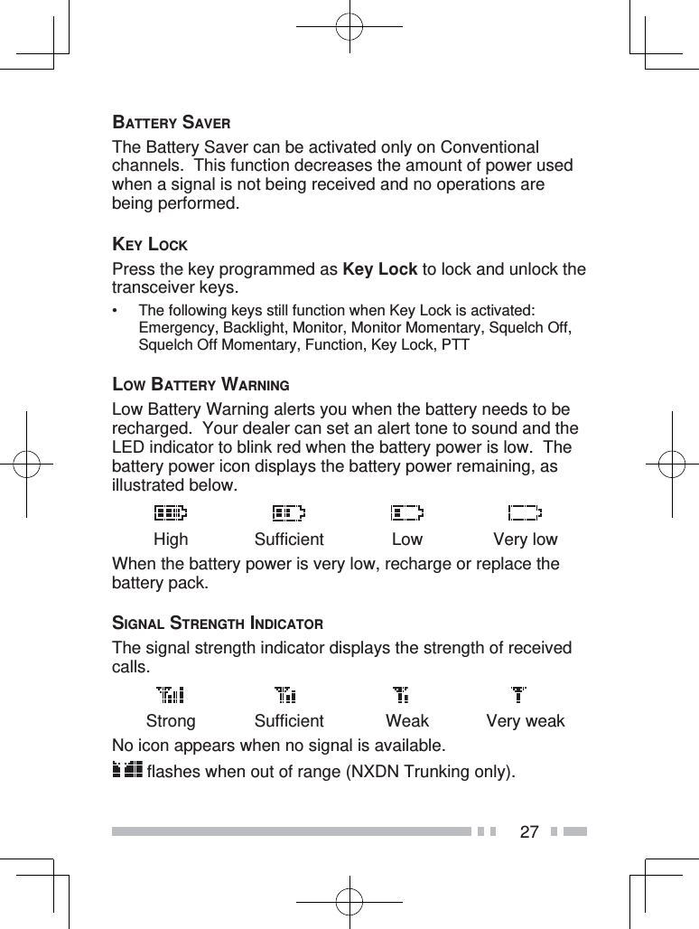
![14Display DescriptionSQUELCH OFF Squelch Off ON/OFFSTACK Stack modeSTATUS Status modeSHORT MESSAGE Short Mesage modeTALK AROUND Talk Around ON/OFFPASSWORD Transceiver Password modeVIBRATOR Vibrator ON/OFFVOICE MEMO Voice Memo modeVOX LEVEL VOX Level modeVOX VOX ON/OFFZONE DEL/ADD Zone Delete/A ddCHARACTER ENTRYThere are 2 methods available for entering characters:1) Pressing the / keys Press / to cycle the characters from A ~ Z, 0 ~ 9, and a space (default settings). You can also assign a character to an optional key and later press that key to recall the assigned character: A ~ Z, a ~ z, 0 ~ 9, or a space and characters.2) Using the DTMF keypad Press the keypad keys to enter characters as shown in the table below:DTMF Key Character Cycle112 A B C 23 D E F 34 G H I 45 J K L 56 M N O 67 P Q R S 78 T U V 89 W X Y Z 90 [space] 0](https://usermanual.wiki/Kenwood-USA/409001/User-Guide-1584961-Page-28.png)