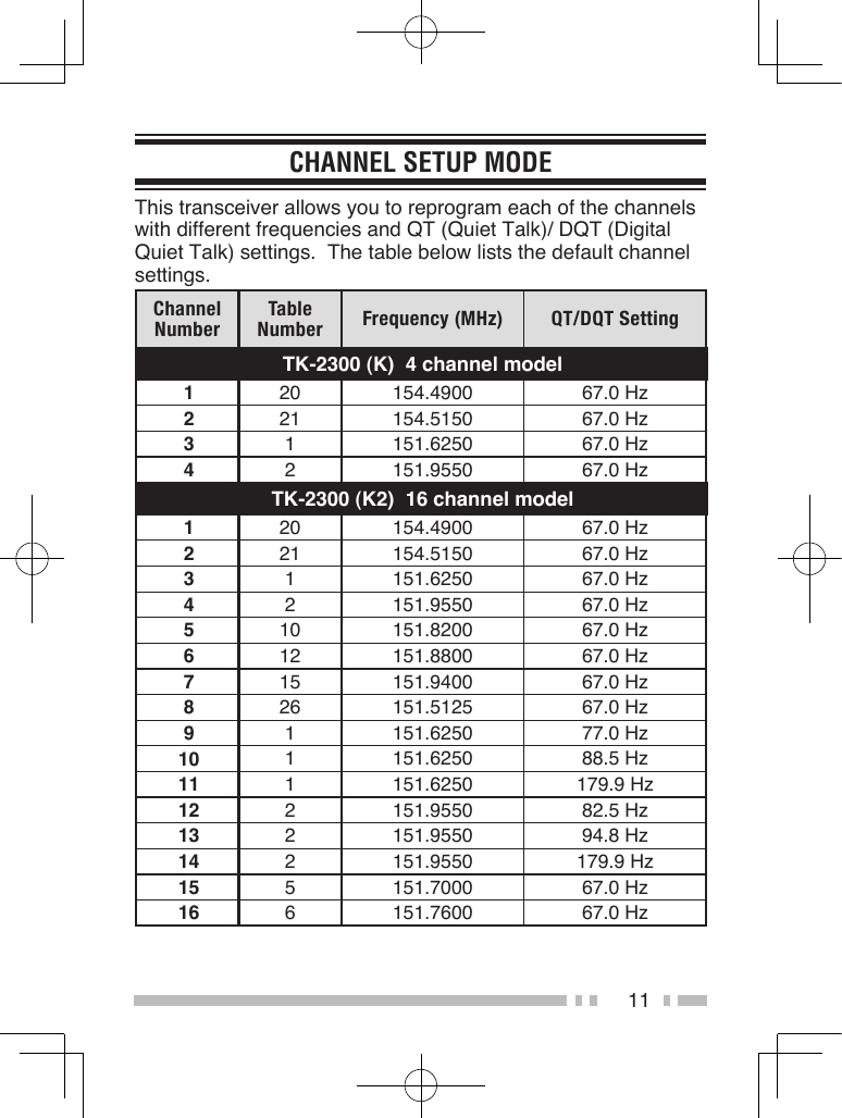
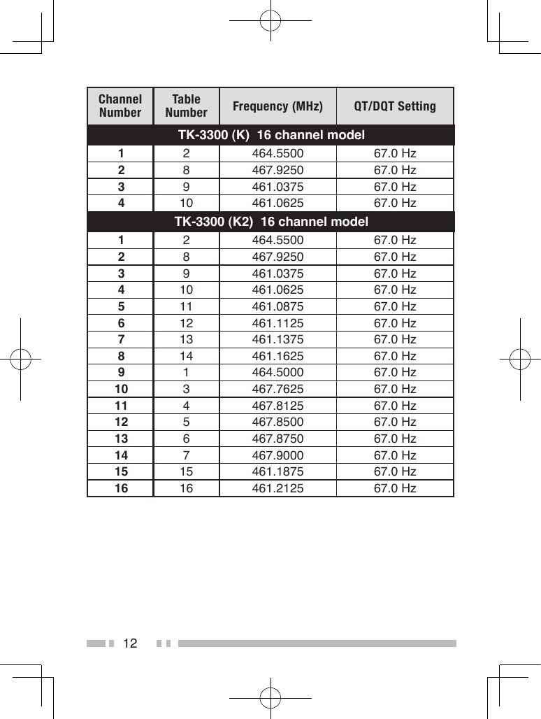
Kenwood USA 413501 VHF-FM Portable Transceiver User Manual Manual Part 1

Kenwood USA Corporation VHF-FM Portable Transceiver Manual Part 1

Manual Part 1

INSTRUCTION MANUAL© B62-2159-00 (K, K2)09 08 07 06 05 04 03 02 01  00 VHF FM TRANSCEIVERTK-2300UHF FM TRANSCEIVERTK-3300
Thank YouWe are grateful for your purchase of this Kenwood product and welcome you to the Business Radio Service (BRS).Your Kenwood 2-way Business Radio is called a “transceiver”, meaning “transmitter & receiver”.  We believe this easy-to-use transceiver will provide you with dependable and reliable communications.  This Kenwood transceiver is a precision device.  Treat it with care, and you will enjoy years of reliable operation.Models Covered bY This ManualTK-2300 (K):  4-channel VHF FM TransceiverTK-3300 (K):  4-channel UHF FM TransceiverTK-2300 (K2):  16-channel VHF FM TransceiverTK-3300 (K2):  16-channel UHF FM TransceiverFeaTures•  4 channels (K) or 16 channels (K2) with 27 VHF operating frequencies (TK-2300) or 89 UHF operating frequencies (TK-3300) and 122 tone/ code settings for each channel allowing you to ignore unwanted calls.•  Built in voice scrambler gives you complete privacy for your conversations.•  Hands free operation when using an optional headset.•  Voice announcement lets you know which channel you have selected and which settings you have made when reassigning key functions and channel settings.
iOperating COnditiOnsOpen locations (no obstructions) Up to 6 miles (approximately 9.6 km)Residential areas (near buildings) Up to 1.5 miles (approximately 2.4 km)In steel/ concrete reinforcedbuildingsUp to 250,000 square feet (approximately 23,220 m2)In high rises Up to 20 floorsNote:  The listed ranges are based on field testing and may vary with your operating conditions and individual transceiver.Terminal DescriptionsSpeaker/ Microphone JacksIt is possible to use a resin-based cover for the Speaker/ Microphone jacks.NO. Name Description Impedance I/O1 PTT / RXD External PTT Input / Serial Data Input CMOS I2 MIC External MIC Input 1.8 kΩ I3 MICIN Internal MIC Output 1.8 kΩ O4 OPTDET External Option Detect High Impedance I5 5M 5V Output 100 Ω O6 AE GND GND −7 TXD Serial Data Output CMOS O8 NC No Connection − −9 SPO Audio Input 8 Ω I10 SPI Received Audio Output 8 Ω OAntenna Terminal50 Ω impedanceBattery TerminalThe battery terminal uses a spring plate.   The negative terminal connects to the chassis ground.   The battery is mounted on the rear side of the transceiver using a latch mounting method.
iiFCC LiCense inFOrmatiOnYour KENWOOD transceiver operates on communications frequencies which are subject to FCC (Federal Communications Commission) Rules & Regulations.  FCC Rules require that all operators using Private Land Mobile radio frequencies obtain a radio license before operating their equipment.  Application for license must be made on FCC form 601, schedules D and H, and Remittance form 159.FAX:  Forms can be obtained by fax from the FCC Fax-On-Demand system.  Call 1-202-418-0177 from your fax machine and request document number 000601 for the form, schedules, and instructions.MAIL:  Forms can be ordered by telephone, and will be sent to you by first class mail.  Call the FCC Forms Hotline at  1-800-418-FORM (1-800-418-3676).INTERNET:  Form 601 and instructions can be downloaded from the FCC Forms website at  http://www.fcc.gov/formpage.htmlBefore filling out your Form 601 application Technical Data section, you must decide on which frequencies you will operate.  See the frequency charts on pages 14 and 15.QUESTIONS?  Call the FCC for license application questions at 1-888-CALL-FCC (1-888-225-5322).
iiiOne or more of the following statements may be applicable:FCC WARNING  This equipment generates or uses radio frequency energy.  Changes or modifications to this equipment may cause harmful interference unless the modifications are expressly approved in the instruction manual.  The user could lose the authority to operate this equipment if an unauthorized change or modification is made.INFORMATION TO THE DIGITAL DEVICE USER REQUIRED BY THE FCC  This equipment has been tested and found to comply with the limits for a Class B digital device, pursuant to Part 15 of the FCC Rules.  These limits are designed to provide reasonable protection against harmful interference in a residential installation.  This equipment generates, uses and can generate radio frequency energy and, if not installed and used in accordance with the instructions, may cause harmful interference to radio communications.  However, there is no guarantee that the interference will not occur in a particular installation.  If this equipment does cause harmful interference to radio or television reception, which can be determined by turning the equipment off and on, the user is encouraged to try to correct the interference by one or more of the following measures:•  Reorient or relocate the receiving antenna.•  Increase the separation between the equipment and receiver.•  Connect the equipment to an outlet on a circuit different from that to which the receiver is connected.•  Consult the dealer for technical assistance.ATTENTION:The RBRC Recycle seal found on Kenwood lithium-ion (Li-ion) battery packs indicates Kenwood’s voluntary participation in an industry program to collect and recycle Li-ion batteries after their operating life has expired.  The RBRC program is an alternative to disposing Li-ion batteries with your regular refuse or in municipal waste streams, which is illegal in some areas.For information on Li-ion battery recycling in your area, call (toll free) 1-800-8-BATTERY (1-800-822-8837).Kenwood’s involvement in this program is part of our commitment to preserve our environment and conserve our natural resources.
ivnOtiCes tO the User◆  Government law prohibits the operation of unlicensed radio transmitters within the territories under government control.◆  Illegal operation is punishable by fine and/or imprisonment.◆  Refer service to qualified technicians only.Safety:  It is important that the operator is aware of, and understands, hazards common to the operation of any transceiver.preCaUtiOns•  Do not charge the transceiver and battery pack when they are wet.•  Ensure that there are no metallic items located between the transceiver and the battery pack.•  Do not use options not specified by Kenwood.•  If the die-cast chassis or other transceiver part is damaged, do not touch the damaged parts.•  If a headset or headphone is connected to the transceiver, reduce the transceiver volume.  Pay attention to the volume level when turning the squelch off.•  Do not place the microphone cable around your neck while near machinery that may catch the cable.•  Do not place the transceiver on unstable surfaces.•  Ensure that the end of the antenna does not touch your eyes.•  When the transceiver is used for transmission for many hours, the radiator and chassis will become hot.  Do not touch these locations when replacing the battery pack.•  Do not immerse the transceiver in water.•  Always switch the transceiver power off before installing optional accessories.•  The charger is the device that disconnects the unit from the AC mains line. The AC plug should be readily accessible.
vTurn the transceiver power off in the following locations:•  In explosive atmospheres (inflammable gas, dust particles, metallic powders, grain powders, etc.).•  While taking on fuel or while parked at gasoline service stations.•  Near explosives or blasting sites.•  In aircrafts. (Any use of the transceiver must follow the instructions and regulations provided by the airline crew.)•  Where restrictions or warnings are posted regarding the use of radio devices, including but not limited to medical facilities.•  Near persons using pacemakers.•  Do not disassemble or modify the transceiver for any reason.•  Do not place the transceiver on or near airbag equipment while the vehicle is running.  When the airbag inflates, the transceiver may be ejected and strike the driver or passengers.•  Do not transmit while touching the antenna terminal or if any metallic parts are exposed from the antenna covering.  Transmitting at such a time may result in a high-frequency burn.•  If an abnormal odor or smoke is detected coming from the transceiver, switch the transceiver power off immediately, remove the battery pack from the transceiver, and contact your Kenwood dealer.•  Use of the transceiver while you are driving may be against traffic laws.  Please check and observe the vehicle regulations in your area.•  Do not expose the transceiver to extremely hot or cold conditions.•  Do not carry the battery pack (or battery case) with metal objects, as they may short the battery terminals.•  Danger of explosion if the battery is incorrectly replaced; replace only with the same type. •  When operating the transceiver in areas where the air is dry, it is easy to build up an electric charge (static electricity).  When using an earphone accessory in such conditions, it is possible for the transceiver to send an electric shock through the earphone and to your ear.  We recommend you use only a speaker/microphone in these conditions, to avoid electric shocks.
viInformation concerning the battery pack:The battery pack includes flammable objects such as organic solvent.  Mishandling may cause the battery to rupture producing flames or extreme heat, deteriorate, or cause other forms of damage to the battery.  Please observe the following prohibitive matters.•  Do not disassemble or reconstruct battery!  The battery pack has a safety function and protection circuit to avoid danger.  If they suffer serious damage, the battery may generate heat or smoke, rupture, or burst into flame.•  Do not short-circuit the battery!  Do not join the + and – terminals using any form of metal (such as a paper clip or wire).  Do not carry or store the battery pack in containers holding metal objects (such as wires, chain-necklace or hairpins).  If the battery pack is short-circuited, excessive current will flow and the battery may generate heat or smoke, rupture, or burst into flame.  It will also cause metal objects to heat up.•  Do not incinerate or apply heat to the battery!  If the insulator is melted, the gas release vent or safety function is damaged, or the electrolyte is ignited, the battery may generate heat or smoke, rupture, or burst into flame.•  Do not use or leave the battery near fire, stoves, or other heat generators (areas reaching over 80°C/ 176°F)!  If the polymer separator is melted due to high temperature, an internal short-circuit may occur in the individual cells and the battery may generate heat or smoke, rupture, or burst into flame.  •  Do not immerse the battery in water or get it wet by other means!  If the battery’s protection circuit is damaged, the battery may charge at extreme current (or voltage) and an abnormal chemical reaction may occur.  The battery may generate heat or smoke, rupture, or burst into flame.•  Do not charge the battery near fire or under direct sunlight!  If the battery’s protection circuit is damaged, the battery may charge at extreme current (or voltage) and an abnormal chemical reaction may occur.  The battery may generate heat or smoke, rupture, or burst into flame.
vii•  Use only the specified charger and observe charging requirements!  If the battery is charged in unspecified conditions (under high temperature over the regulated value, excessive high voltage or current over regulated value, or with a remodeled charger), it may overcharge or an abnormal chemical reaction may occur.  The battery may generate heat or smoke, rupture, or burst into flame.•  Do not pierce the battery with any object, strike it with an instrument, or step on it!  This may break or deform the battery, causing a short-circuit.  The battery may generate heat or smoke, rupture, or burst into flame.•  Do not jar or throw the battery!  An impact may cause the battery to leak, generate heat or smoke, rupture, and/or burst into flame.  If the battery’s protection circuit is damaged, the battery may charge at an abnormal current (or voltage), and an abnormal chemical reaction may occur.  The battery may generate heat or smoke, rupture, or burst into flame.•  Do not use the battery pack if it is damaged in any way!  The battery may generate heat or smoke, rupture, or burst into flame.•  Do not solder directly onto the battery!  If the insulator is melted or the gas release vent or safety function is damaged, the battery may generate heat or smoke, rupture, or burst into flame.•  Do not reverse the battery polarity (and terminals)!  When charging a reversed battery, an abnormal chemical reaction may occur.  In some cases, an unexpected large amount of current may flow upon discharging.  The battery may generate heat or smoke, rupture, or burst into flame.•  Do not reverse-charge or reverse-connect the battery!  The battery pack has positive and negative poles.  If the battery pack does not smoothly connect with a charger or operating equipment, do not force it; check the polarity of the battery.  If the battery pack is reverse-connected to the charger, it will be reverse-charged and an abnormal chemical reaction may occur.  The battery may generate heat or smoke, rupture, or burst into flame.
viii•  Do not touch a ruptured and leaking battery!  If the electrolyte liquid from the battery gets into your eyes, wash your eyes with fresh water as soon as possible, without rubbing your eyes.  Go to the hospital immediately.  If left untreated, it may cause eye-problems.•  Do not charge the battery for longer than the specified time!  If the battery pack has not finished charging even after the regulated time has passed, stop it.  The battery may generate heat or smoke, rupture, or burst into flame.•  Do not place the battery pack into a microwave or high pressure container!  The battery may generate heat or smoke, rupture, or burst into flame.•  Keep ruptured and leaking battery packs away from fire!  If the battery pack is leaking (or the battery emits a bad odor), immediately remove it from flammable areas.  Electrolyte leaking from battery can easily catch on fire and may cause the battery to generate smoke or burst into flame.•  Do not use an abnormal battery!  If the battery pack emits a bad odor, appears to have different coloring, is deformed, or seems abnormal for any other reason, remove it from the charger or operating equipment and do not use it.  The battery may generate heat or smoke, rupture, or burst into flame.
1CONTENTSUNPACKING AND CHECKING EQUIPMENT .......................... 1PREPARATION .......................................................... 2ORIENTATION ........................................................... 6BASIC OPERATIONS ................................................... 8VOICE OPERATED TRANSMISSION (VOX) .......................... 9BACKGROUND OPERATIONS ........................................10CHANNEL SETUP MODE .............................................. 11KEY ASSIGNMENT MODE ............................................ 20TROUBLESHOOTING GUIDE ......................................... 25ALL RESET MODE ..................................................... 26OPTIONAL ACCESSORIES ............................................ 26UNPACKING AND CHECKING EQUIPMENTCarefully unpack the transceiver.  If any of the items listed below are missing or damaged, file a claim with the carrier immediately.SUPPLIED ACCESSORIES•  Battery charger/ AC adapter (KSC-35) ...................................1•  Li-ion Battery pack (KNB-45L) ................................................1•  Speaker/ microphone jack cover ............................................1•  Speaker/ microphone locking bracket ....................................1•  Belt clip (KBH-10) ...................................................................1•  Screw set•  M3 x 6 mm (Black) .................................................................. 1•  M3 x 8 mm .............................................................................. 2•  Instruction manual ..................................................................1Note:  Refer to "PREPARATION" for accessory installation instructions.
2PREPARATIONINSTALLING/ REMOVING THE BATTERY PACK◆  Do not short the battery terminals or dispose of the battery by fire.◆  Never attempt to remove the casing from the battery pack.1  Align the battery pack with the back of the transceiver, then press the battery pack and transceiver firmly together until the release latch on the base of the transceiver locks.2  To remove the battery pack, lift the safety catch on the base of the transceiver, then press the release latch underneath the safety catch.3  While pressing the release latch, pull the battery pack away from the transceiver.
3INSTALLING THE ANTENNAAntennaScrew the antenna into the connector on the top of the transceiver by holding the antenna at its base and turning it clockwise until secure.Note:  The antenna is neither a handle, a key ring retainer, nor a speaker/ microphone attachment point.  Using the antenna in these ways may damage the antenna and degrade your transceiver’s performance.INSTALLING THE BELT CLIPBelt clipIf necessary, attach the belt clip using the two supplied M3 x 8 mm screws.Note:  If the belt clip is not installed, its mounting location may get hot during continuous transmission or when left sitting in a hot environment.Do not use glue which is designed to prevent screw loosening when installing the belt clip, as it may cause damage to the transceiver.  Acrylic ester, which is contained in these glues, may crack the transceiver’s back panel.
4INSTALLING THE COVER OVER THE SPEAKER/ MICROPHONE JACKSSpeaker/ microphone jack cover If you are not using a speaker/ microphone, install the cover over the speaker/ microphone jacks using the supplied M3 x 6 mm screw.Note:  To keep the transceiver water resistant, you must cover the speaker/ microphone jacks with the supplied cover.INSTALLING THE OPTIONAL SPEAKER/ MICROPHONE  (OR HEADSET)Speaker/ microphone locking bracket1  Insert the speaker/ microphone (or headset) plugs into the speaker/ microphone jacks.2  Attach the locking bracket using the supplied M3 x 6 mm screw.Note:  The transceiver is not fully water resistant while using the speaker/ microphone.
5CHARGING THE BATTERY PACKThe battery pack is not charged at the factory; charge it before use. Average battery pack life (calculated using 5% transmit time, 5% receive time, and 90% standby time) is 17 hours.ATTENTION:  Always switch OFF a transceiver equipped with a battery pack before inserting the transceiver into the charger.1  Plug the AC adapter cable into the jack located on the rear of the charger.2  Plug the AC adapter into an AC outlet.3  Slide a battery pack or a transceiver equipped with a battery pack into the charging slot of the charger.•  Make sure the metal contacts of the battery pack mate securely with the charger terminals.•  The indicator lights red and charging begins.4  When charging is completed, the indicator lights green.  Remove the battery pack or the transceiver from the charging slot of the charger.Charging slot Indicator•  It takes approximately 3 hours to charge the battery pack.•  When the charger will not be used for a long time, unplug the AC adapter from the AC outlet.Note:◆  When the indicator blinks red, the battery pack is either defective or the battery pack contacts are not properly mated with those of the charger.◆  The ambient temperature should be between 41°F and 104°F (5°C and 40°C) while charging is in progress.  Charging outside this range may not fully charge the battery.◆  The battery pack life is over when its operating time decreases even though it is fully and correctly charged.  Replace the battery pack.
6ORIENTATIONBattery pack Channel selector  Rotate to change the operating channel.•  To change the operating frequency or QT/DQT settings of a channel, refer to “CHANNEL SETUP MODE” on page 11.•  Channel Annunciation:  When changing channels, the transceiver will announce the newly selected channel number.  LED indicator  For the LED indicator status, refer to page 8. Power switch/ Volume control  Turn clockwise to switch the transceiver ON.  To switch the transceiver OFF, turn counterclockwise until a click sounds.  Rotate to adjust the volume level. PTT (Push to Talk) switch  Press and hold, then speak into the microphone to transmit.Antenna
7 Side 1 key   Press to activate its programmable function. The default setting is Super Lock.•  For function descriptions and details on how to change the function of the Side 1 key, refer to “KEY ASSIGNMENT MODE” on page 20. Side 2 key  Press to activate its programmable function. The default setting is Scan + Temporary Delete.•  For function descriptions and details on how to change the function of the Side 2 key, refer to “KEY ASSIGNMENT MODE” on page 20. Speaker/ microphone jacks  Insert the Speaker/ microphone or Headset plug into this jack.
8BASIC OPERATIONS1  Turn the Power switch/ Volume control clockwise to switch the transceiver power ON.•  A beep sounds.2  Rotate the Channel selector to select your desired channel.•  When you receive an appropriate signal, you will hear audio from the speaker.  Adjust the volume as necessary.3  To make a call, press and hold the PTT switch, then speak into the microphone using your normal speaking voice.•  Hold the microphone approximately 1.5 inches (3 to 4 cm) from your lips.4  Release the PTT switch to receive.Note:  When the battery pack voltage becomes too low, transmission will stop and an alert tone will sound.LED Indicator StatusIndicator Color MeaningLights red TransmittingLights green Receiving a callBlinks red Battery power is low while transmittingBlinks green ScanningBlinks red/orange The selected channel has not been programmed and cannot be used.
9VOICE OPERATED TRANSMISSION (VOX)VOX operation allows you to transmit hands-free.  VOX can only be used if you are using a supported headset.  This function can be turned off for specific channels.To activate VOX and set the VOX Gain level, perform the following steps:1  Connect the headset to the transceiver .•  The VOX function does not activate when a headset is not connected to the accessory terminal of the transceiver.2  With the transceiver power OFF, press and hold the Side 1 key while turning the transceiver power ON.3  Continue to hold the Side 1 key until a beep sounds.•  The LED indicator lights turn orange.•  When the Side 1 key is released, the transceiver will announces the VOX Gain level.4  Press the Side 1 key to select the VOX Gain level (from 1 ~10 or Off).  An audio voice will announce the VOX Gain level.•  Press the Side 2 key to turn VOX ON/OFF for the current channel (you can change this setting for each channel by selecting a channel with the Channel selector).  When turned ON, a beep sounds.  When turned OFF, a double beep sounds.5  Press the PTT switch to save the setting.•  A beep will sound.•  The transceiver announces the new VOX Gain level.6  Turn the transceiver power OFF and then ON again to activate VOX.Note:◆  If a headset is connected to the transceiver while the VOX function is switched ON and the VOX Gain level is configured to a higher, more sensitive level, louder received signals may cause the transceiver to start transmission.◆  The transceiver will automatically return to normal operation if no action is performed for 5 seconds.
10BACKGROUND OPERATIONSTIME-OUT TIMER (TOT)The Time-out Timer prevent callers from using a channel for an extended duration (60 seconds).  If you continuously transmit for the duration, transmission will stop and an alert tone will sound.  To stop the tone, release the PTT switch.BATTERY SAVERWhen activated by your dealer, the Battery Saver function decreases the amount of power used after no signal is present and no operations are being performed for 5 seconds.  When a signal is received or an operation is performed, Battery Saver turns off.Note:  While the Battery Saver is operating, the LED may flash green when receiving a QT/DQT signal which does not match the QT/DQT tone/code set up in your transceiver.LOw BATTERY wARNINGWhile operating the transceiver, the Low Battery Warning sounds an alert tone every 30 seconds and the LED indicator blinks red when the battery needs recharged or replaced.CHANNEL ANNUNCIATIONWhen changing the channel, the transceiver will announce the newly selected channel number. Likewise, the transceiver will announce the current channel after you turn the transceiver power ON.
11CHANNEL SETUP MODEThis transceiver allows you to reprogram each of the channels with different frequencies and QT (Quiet Talk)/ DQT (Digital Quiet Talk) settings.  The table below lists the default channel settings.Channel NumberTable Number Frequency (MHz) QT/DQT SettingTK-2300 (K)  4 channel model120 154.4900 67.0 Hz221 154.5150 67.0 Hz31 151.6250 67.0 Hz42 151.9550 67.0 HzTK-2300 (K2)  16 channel model120 154.4900 67.0 Hz221 154.5150 67.0 Hz31 151.6250 67.0 Hz42 151.9550 67.0 Hz510 151.8200 67.0 Hz612 151.8800 67.0 Hz715 151.9400 67.0 Hz826 151.5125 67.0 Hz91 151.6250 77.0 Hz10 1 151.6250 88.5 Hz11 1 151.6250 179.9 Hz12 2 151.9550 82.5 Hz13 2 151.9550 94.8 Hz14 2 151.9550 179.9 Hz15 5 151.7000 67.0 Hz16 6 151.7600 67.0 Hz
12Channel NumberTable Number Frequency (MHz) QT/DQT SettingTK-3300 (K)  16 channel model12 464.5500 67.0 Hz28 467.9250 67.0 Hz39 461.0375 67.0 Hz410 461.0625 67.0 HzTK-3300 (K2)  16 channel model12 464.5500 67.0 Hz28 467.9250 67.0 Hz39 461.0375 67.0 Hz410 461.0625 67.0 Hz511 461.0875 67.0 Hz612 461.1125 67.0 Hz713 461.1375 67.0 Hz814 461.1625 67.0 Hz91 464.5000 67.0 Hz10 3 467.7625 67.0 Hz11 4 467.8125 67.0 Hz12 5 467.8500 67.0 Hz13 6 467.8750 67.0 Hz14 7 467.9000 67.0 Hz15 15 461.1875 67.0 Hz16 16 461.2125 67.0 Hz
13CHANNEL OPERATING FREQUENCIESTo change the operating frequency of a channel:1  With the transceiver power OFF, press and hold the PTT switch and Side 1 key while turning the transceiver power ON.•  Continue to hold the PTT switch and Side 1 key until the LED lights orange and the transceiver announces “Self”.2  Release the PTT switch and Side 1 key.•  The transceiver announces “Channel”.•  Pressing the Side 1 key or Side 2 key will toggle between QT, DQT, and Channel setup.3  Press and release the PTT switch, then rotate the Channel selector to your desired channel.•  Upon pressing and releasing the PTT switch, a beep will sound and the transceiver announces “Table zero”.4  Press the Side 1 or Side 2 key to increment/ decrement the Table number, to select the new channel frequency.•  Table numbers and their corresponding operating frequencies are provided in the table on page 14.•  A voice announcement will inform you of the currently selected Table number.5  Press the PTT switch to save the setting.•  A beep will sound.•  Repeat steps 3 to 5 to set up another channel.6  Turn the transceiver power OFF and then ON again to activate the new settings.Note:  The transceiver will automatically return to normal operation if no action is performed for 5 seconds.
14TK-2300 Table NumberOperating Frequency (MHz)TK-2300 Table NumberOperating Frequency (MHz)0OFF 14 151.74501151.6250 15 151.77502151.9550 16 151.86503152.8850 17 151.89504152.9150 18 151.92505151.7000 19 152.70006151.7600 20 154.49007152.9450 21 154.51508151.8350 22 154.52759151.8050 23 154.540010 151.5125 24 153.005011 151.6550 25 154.655012 151.6850 26 158.400013 151.7150 27 158.4075TK-3300 Table NumberOperating Frequency (MHz)TK-3300 Table NumberOperating Frequency (MHz)0OFF 14 461.16251464.5000 15 461.18752464.5500 16 461.21253467.7625 17 461.23754467.8125 18 461.26255467.8500 19 461.28756467.8750 20 461.31257467.9000 21 461.33758467.9250 22 461.36259461.0375 23 462.762510 461.0625 24 462.787511 461.0875 25 462.812512 461.1125 26 462.837513 461.1375 27 462.8625
15TK-3300 Table NumberOperating Frequency (MHz)TK-3300 Table NumberOperating Frequency (MHz)28 462.8875 59 462.487529 462.9125 60 462.512530 464.4875 61 467.187531 464.5125 62 467.462532 464.5375 63 467.487533 464.5625 64 467.512534 466.0375 65 451.187535 466.0625 66 451.237536 466.0875 67 451.287537 466.1125 68 451.337538 466.1375 69 451.437539 466.1625 70 451.537540 466.1875 71 451.637541 466.2125 72 452.312542 466.2375 73 452.537543 466.2625 74 452.412544 466.2875 75 452.512545 466.3125 76 452.762546 466.3375 77 452.862547 466.3625 78 456.187548 467.7875 79 456.237549 467.8375 80 456.287050 467.8625 81 456.337551 467.8875 82 456.437552 467.9125 83 456.537553 469.4875 84 456.637554 469.5125 85 457.312555 469.5375 86 457.412556 469.5625 87 457.512557 462.1875 88 457.762558 462.4625 89 457.8625
16QT/ DQT SETTINGSQuiet Talk (QT) and Digital Quiet Talk (DQT) are functions that reject undesired signals on your channel.  You will hear a call only when you receive a signal that contains a matching QT tone or DQT code.  If a call containing a different tone or code is received, squelch will not open and you will not hear the call. Likewise, when transmitting using QT or DQT, the receiving station must have a matching tone or code to hear your call.Be aware that other parties can still hear your calls if they set up their transceiver with the same tone or code.To change the QT/DQT settings of a channel:1  With the transceiver power OFF, press and hold the PTT switch and Side 1 key while turning the transceiver power ON.•  Continue to hold the PTT switch and Side 1 key until the LED lights orange and the transceiver announces “Self”.2  Release the PTT switch and Side 1 key.•  The transceiver announces “Channel”.•  Pressing the Side 1 key or Side 2 key will toggle between QT, DQT, and Channel setup.3  Press the Side 1 or Side 2 key to select QT or DQT setup.•  The transceiver announces “QT” or “DQT”, depending on your selection.4  Press and release the PTT switch, then rotate the Channel selector to your desired channel.•  Upon releasing the PTT switch, the transceiver announces “QT One” or “DQT One”, depending on your selection.5  Press the Side 1 or Side 2 key to increment/ decrement the Tone number, to select the new tone or code.•  Tone numbers and their corresponding tones/ codes are provided in the table on pages 17 and 18.•  Press and hold the Side 1 or Side 2 key to increment/ decrement the QT or DQT number by 5 at a time.•  A voice announcement will inform you of the currently selected QT or DQT number.
176  Press the PTT switch to save the setting.•  A beep will sound.•  Repeat steps 3 to 6 to set up another channel.7  Turn the transceiver power OFF and then ON again to activate the new settings.Note:  The transceiver will automatically return to normal operation if no action is performed for 5 seconds.QT Channel Settings:QT NumberQT FrequencyQT NumberQT FrequencyQT NumberQT Frequency167.0 Hz 15 110.9 Hz 29 179.9 Hz271.9 Hz 16 114.8 Hz 30 186.2 Hz374.4 Hz 17 118.8 Hz 31 192.8 Hz477.0 Hz 18 123.0 Hz 32 203.5 Hz579.7 Hz 19 127.3 Hz 33 210.7 Hz682.5 Hz 20 131.8 Hz 34 218.1 Hz785.4 Hz 21 136.5 Hz 35 225.7 Hz888.5 Hz 22 141.3 Hz 36 233.6 Hz991.5 Hz 23 146.2 Hz 37 241.8 Hz10 94.8 Hz 24 151.4 Hz 38 250.3 Hz11 97.4 Hz 25 156.7 Hz 39 69.3 Hz12 100.0 Hz 26 162.2 Hz off OFF13 103.5 Hz 27 167.9 Hz14 107.2 Hz 28 173.8 Hz
18DQT Channel Settings:DQT NumberDQT CodeDQT NumberDQT CodeDQT NumberDQT Code1D023N 29 D174N 57 D445N2D025N 30 D205N 58 D464N3D026N 31 D223N 59 D465N4D031N 32 D226N 60 D466N5D032N 33 D243N 61 D503N6D043N 34 D244N 62 D506N7D047N 35 D245N 63 D516N8D051N 36 D251N 64 D532N9D054N 37 D261N 65 D546N10 D065N 38 D263N 66 D565N11 D071N 39 D265N 67 D606N12 D072N 40 D271N 68 D612N13 D073N 41 D306N 69 D624N14 D074N 42 D311N 70 D627N15 D114N 43 D315N 71 D631N16 D115N 44 D331N 72 D632N17 D116N 45 D343N 73 D654N18 D125N 46 D346N 74 D662N19 D131N 47 D351N 75 D664N20 D132N 48 D364N 76 D703N21 D134N 49 D365N 77 D712N22 D143N 50 D371N 78 D723N23 D152N 51 D411N 79 D731N24 D155N 52 D412N 80 D732N25 D156N 53 D413N 81 D734N26 D162N 54 D423N 82 D743N27 D165N 55 D431N 83 D754N28 D172N 56 D432N off OFF
19CHANNEL CONFIRMATION MODETo confirm your channel settings:1  With the transceiver power OFF, press and hold the PTT switch while turning the transceiver power ON.•  Continue to hold the PTT switch until the LED lights orange and the transceiver announces “Confirm”.2  Release the PTT switch.•  The transceiver announces the channel table number and Tone number of the selected channel.3  Rotate the Channel selector to your desired channel within 5 seconds, otherwise the operation will cancel.•  The transceiver announces the channel table number and Tone number of the current channel.Note:  The transceiver will automatically return to normal operation if no action is performed for 5 seconds.
20KEY ASSIGNMENT MODEThis transceiver allows you to reprogram the Side 1 and Side 2 keys with any of the functions listed in the table below. Explanations on the use of each function are provided under “PROGRAMMABLE FUNCTIONS”, on page 22.Table Number Function Name0None (no function)1Calling Alert2Key Lock3Key Lock with Status Memory4Monitor5Monitor Momentary6Scan7Scan + Temporary Delete  (Side 2 key default)8Scrambler9Squelch Off10 Squelch Off Momentary11 Temporary Delete12 Super Lock (Side 1 key default)13 Temporary Delete
21To change the functions of the Side 1 and Side 2 keys:1  With the transceiver power OFF, press and hold the Side 1 and Side 2 keys while turning the transceiver power ON.•  Continue to hold the Side 1 and Side 2 keys until the LED lights orange and the transceiver announces “Setup”.2  Continue to press and hold the key to be reprogrammed (either the Side 1 or Side 2 key), while releasing the remaining key.•  The transceiver will announce “Table zero”.•  If you continue to hold both keys, or if you release both keys, the operation will cancel in 5 seconds.3  Release the key.4  Press the Side 1 or Side 2 key to increment/ decrement the number, to select the new key function.•  Table numbers and their corresponding functions are provided in the table on page 20.•  A voice announcement will inform you of the currently selected Table number.5  Press the PTT switch to save the setting.•  A beep will sound and the transceiver will announce the new Table number.6  Turn the transceiver power OFF and then ON again to activate the new settings.Note:  The transceiver will automatically return to normal operation if no action is performed for 5 seconds.
22PROGRAMMABLE FUNCTIONS■  Calling Alert Calling alert tones help identify yourself to party members and inform them that you are calling.  Your dealer can set up your transceiver with 1 of 10 calling alert tones. If each party member uses a different tone, it is easy to know who is calling. To make a call, press and hold the PTT switch, then press the key programmed as Calling Alert.•   Release the key to end the tone.■  Key LockPress and hold this key for 1 second to lock/ unlock the transceiver keys.The following keys/ functions can still be used when Key Lock is active:Calling Alert, Key Lock, Monitor, Monitor Momentary, PTT, Squelch Off, Squelch Off Momentary, and Volume. •  When the transceiver power is turned OFF and then ON again, the Key Lock function will be cancelled.■  Key Lock with Status MemoryThis operates the same as Key Lock except that when the transceiver power is turned OFF and then ON again, the keys remain locked.  Without Status Memory, when the transceiver power is turned OFF and then ON again, the Key Lock function will be cancelled.■  MonitorMomentarily press this key to deactivate QT or DQT signaling. Press the key again to return to normal operation.■  Monitor MomentaryPress and hold this key to deactivate QT or DQT signaling. Release the key to return to normal operation.
23■  ScanScan is useful for monitoring signals on the transceiver channels. When scanning, the transceiver checks for a signal on each channel and only stops if a signal is present.If the QT/DQT matches, the transceiver stops at the channel and opens the squelch so you can listen to the call. If the QT/DQT does not match, the call is ignored and scanning continues.■  Scan + Temporary Delete (Side 2 key default)Press this key to start scanning the transceiver channels. When Scan pauses at an undesired channel, you can remove that channel from the scanning sequence by pressing and holding this key for 3 seconds.■  ScramblerThe Scrambler function allows you to hold a conversation in complete privacy. When the Scrambler function is activated, any other party that is listening to your channel will be unable to understand your conversation.■  Squelch OffMomentarily press this key to hear background noise.  Press the key again to return to normal operation.■  Squelch Off MomentaryPress and hold this key to hear background noise.  Release the key to return to normal operation.■  Temporary DeleteWhen Scan pauses at an undesired channel, you can remove that channel from the scanning sequence by pressing and holding this key for 1 second.
24■  Super Lock (Side 1 key default)Super Lock locks the same keys as Key Lock.  Press and hold this key for 4 seconds to lock the transceiver keys. To deactivate Super Lock, with the transceiver power OFF, press and hold the Side 2 key for 2 seconds while turning the transceiver power ON.•  When the LED lights orange, release the Side 2 key. A confirmation tone will sound.■  Low Transmit PowerPress this key to change the transmit power to low power.
25TROUBLESHOOTING GUIDEProblem SolutionCannot turn the transceiver power ON.•  The battery pack may be dead.     Recharge or replace the battery pack.•  The battery pack may not be installed correctly.  Remove the battery pack and install again.Battery power dies shortly after charging.•  The battery pack life is finished. Replace the battery pack with a new one.Cannot talk to or hear other members in your group.•  Make sure you are using the same frequency and QT/DQT settings as the other members in your group.•  Other group members may be using the Scrambler function.  Turn on your transceiver’s Scrambler.•  Other group members may be too far away.  Make sure you are within range of the other transceivers.Other voices (besides group members’) are present on the channel.•  Change the QT/DQT settings. Make sure all group members change the settings on their transceivers to match the new QT/DQT setting.
26ALL RESET MODEAt some point in time, you may desire to reset the transceiver settings to their default values. This function will reset all channels to their default frequencies and QT/DQT, the VOX function to its default status, and all keys to their default functions.To reset the transceiver:1  With the transceiver power OFF, press and hold the PTT switch, the Side 1 key, and the Side 2 key while turning the transceiver power ON.•  Continue to hold the keys for 2 seconds, until the LED lights orange.2  Release the keys.•  The keys must be released within 1 second after the LED lights orange, otherwise All Reset Mode will cancel.•  The transceiver announces “Confirm” and returns to normal operation.OPTIONAL ACCESSORIES•   KMC-17 (Speaker/ microphone)•   KMC-21 (Speaker/ microphone)•   KHS-1 (Headset)•   KHS-22 (Headset)•   KNB-45L (Li-ion battery pack)•   KSC-35 (Rapid charger)•   KSC-356 (Multiple charger)•   KBH-10 (Belt clip)•   KWR-1 (Water resistant bag)
RADIO FREQUENCY ENERGY SAFETY INFORMATIONThis KENWOOD transceiver has been evaluated and complies with the standards listed below, inregards to Radio Frequency (RF) energy and electromagnetic energy (EME) generated by thetransceiver.•FCC RF exposure limits for Occupational Use Only.  RF Exposure limits adopted by the FCC are generallybased on recommendations from the National Council on Radiation Protection and Measurements, & theAmerican National Standards Institute.•FCC OET Bulletin 65 Edition 97-01 Supplement C•American National Standards Institute (C95.1 – 1992)•American National Standards Institute (C95.3 – 1992)This KENWOOD transceiver generates RF EME while transmitting.  RF EME (Radio Frequency Electric &Magnetic Energy) has the potential to cause slight thermal, or heating effects to any part of your body lessthan the recommended distance from this radio transmitter’s antenna.  RF energy exposure is determinedprimarily by the distance to and the power of the transmitting device.  In general, RF exposure isminimized when the lowest possible power is used or transmission time is kept to the minimum requiredfor consistent communications, and the greatest distance possible from the antenna to the body ismaintained.  The transceiver has been designed for and is classified for Occupational Use Only.Occupational/ controlled exposure limits are applicable to situations in which persons are exposed to RFenergy as a consequence of their employment, and such persons have been made aware of the potentialfor exposure and can exercise control over their exposure.  This means you can use the transceiver only ifyou are aware of the potential hazards of operating a transceiver and are familiar in ways to minimizethese hazards.  This transceiver is not intended for use by the general public in uncontrolled environments.Uncontrolled environment exposure limits are applicable to situations in which the general public may beexposed to RF energy, or in which the persons who are exposed as a consequence of their employmentmay not be fully aware of the potential for exposure or cannot exercise control over their exposure.The following list provides you with the information required to ensure that you are aware of RFexposure and of how to operate this transceiver so that the FCC RF exposure limitations are notexceeded.•While transmitting (holding the PTT switch or speaking with VOX enabled), always keep the antenna andthe radio at least 3 cm (1 3/16 inches) from your body or face, as well as from any bystanders.  A LED onthe top of the radio shows red when the transmitter is operating in both PTT and VOX modes.•Do not transmit for more than 50% of the total transceiver use time; transmitting over 50% of the total use timemay exceed the limits in accordance to the FCC RF exposure requirements.  Nominal transceiver operation is5% transmission time, 5% reception time, and 90% stand-by time.•Use only the specified antenna for this transceiver; this may be either the antenna provided with thetransceiver or another antenna authorized by KENWOOD.Use only KENWOOD authorized accessories (antennas, battery packs, belt clips, Speaker/ Mics orheadsets etc.): When worn on the body, always place the radio in a KENWOOD recommended clip orcarrying case meant for this product. The use of other than recommended or approved body- wornaccessories may result in RF exposure levels which exceed the FCC’s occupational/ controlledenvironment RF exposure limits.To ensure that your exposure to RF EME is within the FCC limits for occupational use, you must observeand adhere to the above points.Electromagnetic Interference CompatibilityElectronic devices are susceptible to electromagnetic interference (EMI) if they are not adequatelyshielded or designed for electromagnetic compatibility.  Because this transceiver generates RF energy,it can cause interference to such equipment.•Turn OFF your transceiver where signs are posted to do so.  Hospitals and health care facilities useequipment that is sensitive to electromagnetic radiation.•Turn OFF your transceiver while on board an aircraft when so instructed.  Use of the transceiver must be inaccordance with airline regulations and/or crew instructions. B59-2420-00

Navigation menu