Kenwood USA 413700 VHF FM Transceiver User Manual Instruction Manual
Kenwood USA Corporation VHF FM Transceiver Instruction Manual
Instruction Manual

© B62-2238-00 (K,M,P)
09 08 07 06 05 04 03 02 01 00
VHF FM TRANSCEIVER/
UHF FM TRANSCEIVER
INSTRUCTION MANUAL
ÉMETTEUR-RÉCEPTEUR FM VHF/
ÉMETTEUR-RÉCEPTEUR FM UHF
MODE D’EMPLOI
TRANSCEPTOR FM VHF/
TRANSCEPTOR FM UHF
MANUAL DE INSTRUCCIONES
TK-2312/ TK-3312

VHF FM TRANSCEIVER/
UHF FM TRANSCEIVER
TK-2312/ TK-3312
INSTRUCTION MANUAL
ENGLISH

i
ATTENTION:
The RBRC Recycle seal found on Kenwood lithium-ion
(Li-ion) battery packs indicates Kenwood’s voluntary
participation in an industry program to collect and recycle
Li-ion batteries after their operating life has expired.
The RBRC program is an alternative to disposing Li-ion
batteries with your regular refuse or in municipal waste
streams, which is illegal in some areas.
For information on Li-ion battery recycling in your area, call (toll free)
1-800-8-BATTERY (1-800-822-8837).
Kenwood’s involvement in this program is part of our commitment to
preserve our environment and conserve our natural resources.
ATTENTION:
The RBRC Recycle seal found on Kenwood nickel
metal hydride (Ni-MH) battery packs indicates Kenwood’s
voluntary participation in an industry program to collect
and recycle Ni-MH batteries after their operating life
has expired. The RBRC program is an alternative to
disposing Ni-MH batteries with your regular refuse or in
municipal waste streams, which is illegal in some areas.
For information on
Ni-MH
battery recycling in your area, call (toll free)
1-800-8-BATTERY (1-800-822-8837).
Kenwood’s involvement in this program is part of our commitment to
preserve our environment and conserve our natural resources.
Thank You
We are grateful you have chosen Kenwood for your land
mobile radio applications.
noTices To The user
◆ Government law prohibits the operation of unlicensed radio
transmitters within the territories under government control.
◆ Illegal operation is punishable by fine and/or imprisonment.
◆ Refer service to qualified technicians only.
Safety: It is important that the operator is aware of, and
understands, hazards common to the operation of any
transceiver.

ii
One or more of the following statements may be
applicable:
FCC WARNING
This equipment generates or uses radio frequency energy. Changes
or modifications to this equipment may cause harmful interference
unless the modifications are expressly approved in the instruction
manual. The user could lose the authority to operate this equipment if
an unauthorized change or modification is made.
INFORMATION TO THE DIGITAL DEVICE USER REQUIRED BY
THE FCC
This equipment has been tested and found to comply with the limits
for a Class B digital device, pursuant to Part 15 of the FCC Rules.
These limits are designed to provide reasonable protection against
harmful interference in a residential installation.
This equipment generates, uses and can generate radio frequency
energy and, if not installed and used in accordance with the instructions,
may cause harmful interference to radio communications. However,
there is no guarantee that the interference will not occur in a particular
installation. If this equipment does cause harmful interference to
radio or television reception, which can be determined by turning the
equipment off and on, the user is encouraged to try to correct the
interference by one or more of the following measures:
• Reorient or relocate the receiving antenna.
• Increase the separation between the equipment and receiver.
• Connect the equipment to an outlet on a circuit different from that
to which the receiver is connected.
• Consult the dealer for technical assistance.

iii
Terminal DescripTions
Speaker/ Microphone Jacks
You can use a resin-based cover for the Speaker/ Microphone
jacks.
No. Name Description Impedance I/O
1 PTT / RXD External PTT Input / Serial
Data Input CMOS I
2 MIC External MIC Input 1.8 kΩ I
3 MICIN Internal MIC Output 1.8 kΩ O
4 OPTDET External Option Detect High Impedance I
5 5M 5V Output 100 Ω O
6 AE GND GND −
7 TXD Serial Data Output CMOS O
8 NC No Connection − −
9 SPO Audio Input 8 Ω I
10 SPI Received Audio Output 8 Ω O
Antenna Terminal
50 Ω impedance
Battery Terminal
The battery terminal uses a spring plate.
The negative terminal connects to the chassis ground.
The battery is mounted on the rear side of the transceiver using a
latch mounting method.
Firmware Copyrights
The title to and ownership of copyrights for firmware embedded in
Kenwood product memories are reserved for Kenwood Corporation.

iv
precauTions
• Do not charge the transceiver and battery pack when they are wet.
• Ensure that there are no metallic items located between the
transceiver and the battery pack.
• Do not use options not specified by Kenwood.
• If the die-cast chassis or other transceiver part is damaged, do not
touch the damaged parts.
• If a headset or headphone is connected to the transceiver, reduce
the transceiver volume. Pay attention to the volume level when
turning the squelch off.
• Do not place the microphone cable around your neck while near
machinery that may catch the cable.
• Do not place the transceiver on unstable surfaces.
• Ensure that the end of the antenna does not touch your eyes.
• When the transceiver is used for transmission for many hours, the
radiator and chassis will become hot. Do not touch these locations
when replacing the battery pack.
• Do not immerse the transceiver in water.
• Always switch the transceiver power off before installing optional
accessories.
• For safety reasons, we recommend that the AC adapter (for the
battery charger) should be connected to an easily accessible AC
socket.

v
Turn the transceiver power off in the following locations:
• In explosive atmospheres (inflammable gas, dust particles, metallic
powders, grain powders, etc.).
• While taking on fuel or while parked at gasoline service stations.
• Near explosives or blasting sites.
• In aircrafts. (Any use of the transceiver must follow the instructions
and regulations provided by the airline crew.)
• Where restrictions or warnings are posted regarding the use of
radio devices, including but not limited to medical facilities.
• Near persons using pacemakers.
• Do not disassemble or modify the transceiver for any reason.
• Do not place the transceiver on or near airbag equipment while the
vehicle is running. When the airbag inflates, the transceiver may
be ejected and strike the driver or passengers.
• Do not transmit while touching the antenna terminal or if any
metallic parts are exposed from the antenna covering. Transmitting
at such a time may result in a high-frequency burn.
• If an abnormal odor or smoke is detected coming from the
transceiver, switch the transceiver power off immediately, remove
the battery pack from the transceiver, and contact your Kenwood
dealer.
• Use of the transceiver while you are driving may be against traffic
laws. Please check and observe the vehicle regulations in your
area.
• Do not expose the transceiver to extremely hot or cold conditions.
• Do not carry the battery pack (or battery case) with metal objects,
as they may short the battery terminals.
• When operating the transceiver in areas where the air is dry, it is
easy to build up an electric charge (static electricity). When using
a earphone accessory in such conditions, it is possible for the
transceiver to send an electric shock through the earphone and to
your ear. We recommend you use only a speaker/microphone in
these conditions, to avoid electric shocks.

vi
Information concerning the battery pack:
The battery pack includes flammable objects such as organic
solvent. Mishandling may cause the battery to rupture
producing flames or extreme heat, deteriorate, or cause other
forms of damage to the battery. Please observe the following
prohibitive matters.
• Do not disassemble or reconstruct battery!
The battery pack has a safety function and protection circuit to
avoid danger. If they suffer serious damage, the battery may
generate heat or smoke, rupture, or burst into flame.
• Do not short-circuit the battery!
Do not join the + and – terminals using any form of metal (such
as a paper clip or wire). Do not carry or store the battery pack in
containers holding metal objects (such as wires, chain-necklace or
hairpins). If the battery pack is short-circuited, excessive current will
flow and the battery may generate heat or smoke, rupture, or burst
into flame. It will also cause metal objects to heat up.
• Do not incinerate or apply heat to the battery!
If the insulator is melted, the gas release vent or safety function is
damaged, or the electrolyte is ignited, the battery may generate
heat or smoke, rupture, or burst into flame.
• Do not leave the battery near fire, stoves, or other heat
generators (areas reaching over 80°C/ 176°F)!
If the polymer separator is melted due to high temperature, an
internal short-circuit may occur in the individual cells and the
battery may generate heat or smoke, rupture, or burst into flame.
• Do not immerse the battery in water or get it wet by other
means!
If the battery’s protection circuit is damaged, the battery may
charge at extreme current (or voltage) and an abnormal chemical
reaction may occur. The battery may generate heat or smoke,
rupture, or burst into flame.
• Do not charge the battery near fire or under direct sunlight!
If the battery’s protection circuit is damaged, the battery may
charge at extreme current (or voltage) and an abnormal chemical
reaction may occur. The battery may generate heat or smoke,
rupture, or burst into flame.

vii
• Use only the specified charger and observe charging
requirements!
If the battery is charged in unspecified conditions (under high
temperature over the regulated value, excessive high voltage or
current over regulated value, or with a remodeled charger), it may
overcharge or an abnormal chemical reaction may occur. The
battery may generate heat or smoke, rupture, or burst into flame.
• Do not pierce the battery with any object, strike it with an
instrument, or step on it!
This may break or deform the battery, causing a short-circuit. The
battery may generate heat or smoke, rupture, or burst into flame.
• Do not jar or throw the battery!
An impact may cause the battery to leak, generate heat or smoke,
rupture, and/or burst into flame. If the battery’s protection circuit
is damaged, the battery may charge at an abnormal current (or
voltage), and an abnormal chemical reaction may occur. The
battery may generate heat or smoke, rupture, or burst into flame.
• Do not use the battery pack if it is damaged in any way!
The battery may generate heat or smoke, rupture, or burst into
flame.
• Do not solder directly onto the battery!
If the insulator is melted or the gas release vent or safety function
is damaged, the battery may generate heat or smoke, rupture, or
burst into flame.
• Do not reverse the battery polarity (and terminals)!
When charging a reversed battery, an abnormal chemical reaction
may occur. In some cases, an unexpected large amount of current
may flow upon discharging. The battery may generate heat or
smoke, rupture, or burst into flame.
• Do not reverse-charge or reverse-connect the battery!
The battery pack has positive and negative poles. If the battery
pack does not smoothly connect with a charger or operating
equipment, do not force it; check the polarity of the battery. If the
battery pack is reverse-connected to the charger, it will be reverse-
charged and an abnormal chemical reaction may occur. The
battery may generate heat or smoke, rupture, or burst into flame.

viii
• Do not touch a ruptured and leaking battery!
If the electrolyte liquid from the battery gets into your eyes, wash
your eyes with fresh water as soon as possible, without rubbing
your eyes. Go to the hospital immediately. If left untreated, it may
cause eye-problems.
• Do not charge the battery for longer than the specified time!
If the battery pack has not finished charging even after the
regulated time has passed, stop it. The battery may generate heat
or smoke, rupture, or burst into flame.
• Do not place the battery pack into a microwave or high
pressure container!
The battery may generate heat or smoke, rupture, or burst into
flame.
• Keep ruptured and leaking battery packs away from fire!
If the battery pack is leaking (or the battery emits a bad odor),
immediately remove it from flammable areas. Electrolyte leaking
from battery can easily catch on fire and may cause the battery to
generate smoke or burst into flame.
• Do not use an abnormal battery!
If the battery pack emits a bad odour, appears to have different
coloring, is deformed, or seems abnormal for any other reason,
remove it from the charger or operating equipment and do not use
it. The battery may generate heat or smoke, rupture, or burst into
flame.

ix
CONTENTS
UNPACKING AND CHECKING EQUIPMENT .....................................1
Supplied AcceSSorieS ............................................................1
PREPARATION .....................................................................................2
inStAlling/ removing the BAttery pAck ..........................2
inStAlling the AntennA .........................................................3
inStAlling the Belt clip .........................................................3
inStAlling the SpeAker/ microphone JAckS cover .....4
inStAlling the optionAl SpeAker/ microphone
(or heAdSet) ...............................................................................4
chArging the BAttery pAck .................................................5
ORIENTATION .......................................................................................6
diSplAy..........................................................................................8
PROGRAMMABLE AUXILIARY FUNCTIONS ...................................10
BASIC OPERATIONS .........................................................................11
Switching power on/ oFF ....................................................11
AdJuSting the volume ..........................................................11
Selecting A Zone And chAnnel .........................................12
trAnSmitting ...........................................................................12
receiving ...................................................................................12
SCAN ...................................................................................................13
priority ScAn...........................................................................13
temporAry chAnnel lockout ...........................................13
ScAn delete/Add .....................................................................14
ScAn revert .............................................................................14
DTMF CALLS ......................................................................................15
AutodiAl .....................................................................................15
Stun .............................................................................................15
dtmF numBer diSplAy ............................................................15

x
SIGNALING .........................................................................................16
Quiet tAlk (Qt)/ digitAl Quiet tAlk (dQt) .........................16
optionAl SignAling ...............................................................16
operAtor SelectABle tone (oSt) .....................................16
FleetSync ............................................................................................17
SelcAll (Selective cAlling) ................................................17
StAtuS meSSAgeS ....................................................................18
Short meSSAgeS .....................................................................19
VOICE OPERATED TRANSMISSION (VOX) .....................................20
voX operAtion .........................................................................20
voX gAin level .........................................................................20
ADVANCED OPERATIONS ................................................................21
trAnSmit power .....................................................................21
cAlling Alert ...........................................................................21
key lock.....................................................................................21
emergency cAllS ...................................................................22
tAlk Around .............................................................................22
voice ScrAmBler ....................................................................23
monitor/ SQuelch oFF ..........................................................24
trAnSceiver BAcklight ........................................................24
direct Zone chAnnel ............................................................24
BACKGROUND OPERATIONS ..........................................................25
time-out timer (tot) ..............................................................25
BAttery SAver .........................................................................25
BAttery power indicAtor ...................................................25
SignAl Strengtkh indicAtor ..............................................25
BuSy chAnnel lockout (Bcl) ..............................................26
compAnder ...............................................................................26
ptt id ...........................................................................................26

1
Carefully unpack the transceiver. If any of the items listed
below are missing or damaged, file a claim with the carrier
immediately.
• Antenna ..................................................................................1
• Battery charger .......................................................................1
P type: KSC-31
K and M types: KSC-35
• Battery pack ............................................................................1
P type: KNB-29N Ni-MH Battery pack
K and M types: KNB-45L Li-ion Battery pack
• Speaker/ microphone jack cover ............................................1
• Speaker/ microphone locking bracket ....................................1
• Belt clip (KBH-10) ...................................................................1
• Screw set
M3 x 6 mm (Black) ................................................................. 1
M3 x 8 mm ............................................................................. 2
• Instruction manual ..................................................................1
Note: Refer to "PREPARATION" {page 2} for accessory installation
instructions.
2
◆ Do not short the battery terminals or dispose of the battery by
fire.
◆ Never attempt to remove the casing from the battery pack.
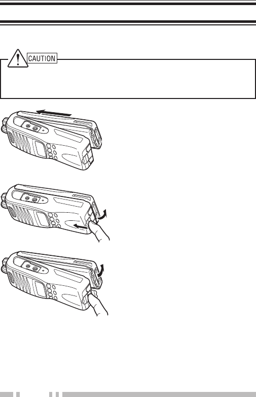
1 Align the battery pack with the
back of the transceiver, then
press the battery pack and
transceiver firmly together until
the release latch on the base
of the transceiver locks.
2 To remove the battery pack, lift
the safety catch on the base of
the transceiver, then press the
release latch underneath the
safety catch.
3 While pressing the release
latch, pull the battery pack
away from the transceiver.
3
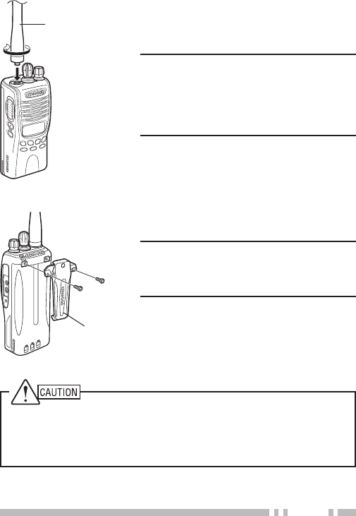
Antenna
Screw the antenna into the connector
on the top of the transceiver by
holding the antenna at its base and
turning it clockwise until secure.
Note: The antenna is neither a handle,
a key ring retainer, nor a speaker/
microphone attachment point. Using
the antenna in these ways may
damage the antenna and degrade your
transceiver’s performance.
Belt clip
If necessary, attach the belt clip using
the two supplied M3 x 8 mm screws.
Note: If the belt clip is not installed, its
mounting location may get hot during
continuous transmission or when left
sitting in a hot environment.
Do not use glue which is designed to prevent screw loosening when
installing the belt clip, as it may cause damage to the transceiver.
Acrylic ester, which is contained in these glues, may crack the
transceiver’s back panel.
4
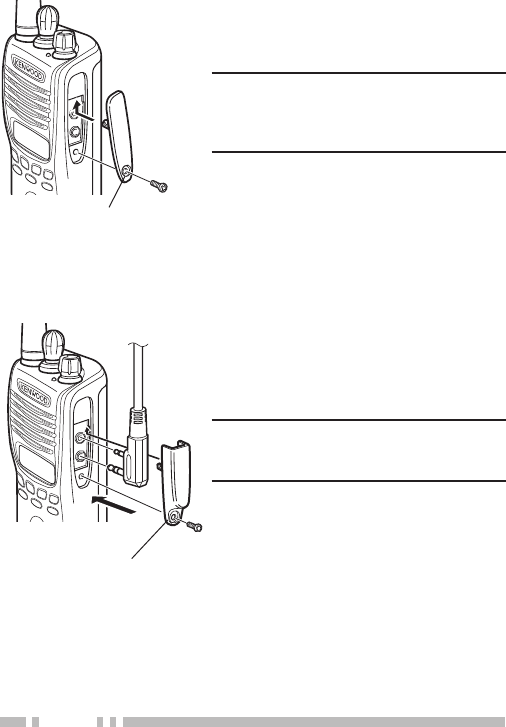
Speaker/ microphone
jack cover
If you are not using a speaker/
microphone, install the cover over
the speaker/ microphone jacks using
the supplied M3 x 6 mm screw.
Note: To keep the transceiver water
resistant, you must cover the speaker/
microphone jacks with the supplied
cover.
Speaker/ microphone locking
bracket
1 Insert the speaker/ microphone
(or headset) plugs into the
speaker/ microphone jacks.
2 Attach the locking bracket using
the supplied M3 x 6 mm screw.
Note: The transceiver is not fully
water resistant while using the
speaker/ microphone.
5
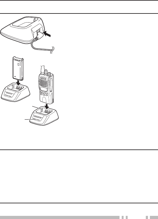
The battery pack is not charged at the factory; charge it before
use.
ATTENTION: Always switch OFF a transceiver equipped with a
battery pack before inserting the transceiver into the charger.
1 Plug the AC adapter cable into the
jack on the rear of the charger.
2 Plug the AC adapter into an AC
outlet.
3 Slide a battery pack or transceiver
equipped with a battery pack into
the charging slot of the charger.
• Make sure the metal contacts of the
battery pack mate securely with the
charger terminals.
• The indicator lights red and
charging begins.
4 When charging is complete, the
indicator lights green. Remove the
battery pack or transceiver from the
charger.
• It takes approximately 3 hours to
charge the battery pack.
• When the charger will not be used
for a long time, unplug the AC
adapter from the AC outlet.
Charging slot
Indicator
Note:
◆ When the indicator blinks red, the battery pack is either
defective or the battery pack contacts are not properly mated
with those of the charger.
◆ The ambient temperature should be between 41°F and 104°F
(5°C and 40°C) while charging is in progress. Charging outside
this range may not fully charge the battery.
◆ The battery pack life is over when its operating time decreases even
though it is fully and correctly charged. Replace the battery pack.
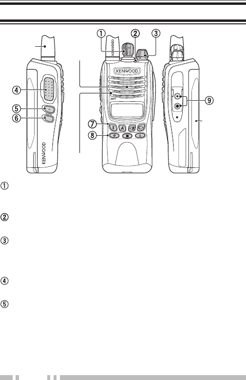
6
Battery pack
Selector
Rotate to change the operating zone or channel.
The default setting is [Zone Up/ Down].
LED indicator
Refer to the table on page 7 for the LED indicator status.
Power switch/ Volume control
Turn clockwise to switch the transceiver ON. To switch the
transceiver OFF, turn counterclockwise until a click sounds.
Rotate to adjust the volume level.
PTT (Push to Talk) switch
Press and hold, then speak into the microphone to transmit.
Side 1 key
Press to activate its programmable function.
The default setting is [Squelch Off Momentary].
Antenna Speaker
Microphone
7
Side 2 key
Press to activate its programmable function.
The default setting is [None] (no function).
S, A, <B, C> keys
Press to activate their programmable functions.
S key: The default setting is [None] (no function).
A key: The default setting is [None] (no function).
<B key: The default setting is [Channel Down].
C> key: The default setting is [Channel Up].
, , keys
Press to activate their programmable functions.
The default setting is [None] (no function).
Speaker/ Microphone jacks
Insert the Speaker/ Microphone or Headset plug into this
jack.
LED Indicator Status
Indicator Color Meaning
Lights red Transmitting
Lights green Receiving a call
Lights orange While VOX level setup
Blinks red Battery power is low while transmitting
Blinks green Scanning
Blinks orange* Receiving an encoded call (FleetSync,
DTMF signaling, etc.)
* Your dealer can change this setting to blue, instead of orange, for
FleetSync operation.
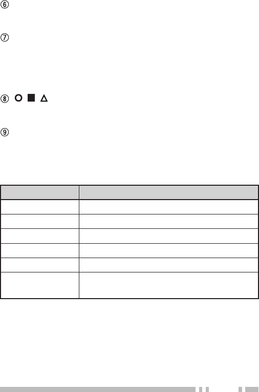
8
Indicator Description
Displays the strength of received
signals {page 25}.
Appears when the Monitor or Squelch
Off function has been activated.
Appears when using 2-tone, DTMF, or
QT/DQT + Optional Signaling.
Appears while using the Talk Around
function.
Appears while scanning.
Appears when a message is stored in
the transceiver stack memory. Blinks
when a new message has arrived.
The selected channel is set as a
Priority channel.
Appears while using low transmit power
on the selected channel.
Appears when the Scrambler function
has been activated.
Displays the current battery status
{page 25}.
The selected zone is added to the
scanning sequence.

9
Indicator Description
The selected channel is added to the
scanning sequence.
Appears while using the VOX function.
Appears when the AUX function has
been activated.
Displays the zone and channel
number or name as well as FleetSync
messages and DTMF codes.

10
The Side 1, Side 2, S, A, <B, C>, , , and keys can be
programmed with the functions listed below. Please contact
your dealer for further details on these functions.
Note:
The Selector can be programmed as either [Zone Up/Down]
or [Channel Up/Down].
• None (No function)
• 2-tone
• Autodial
• Call 1
• Call 2
• Channel Down
• Channel Up
• Calling Alert
• Direct Zone Channel
• Display Character
• Emergency
• Key Lock
• Lamp
• Lone Worker
• Low Transmit Power
• Monitor
• Monitor Momentary
• Operator Selectable Tone
(OST)
• Scan
• Scan Del/Add
• Scrambler
• Selcall
• Selcall+Status
• Squelch Off
• Squelch Off Momentary
• Squelch Level
• Status
• Talk Around
• Status
• VOX
• Zone Down
• Zone Up

11
Turn the Power switch/ Volume control clockwise to switch the
transceiver ON.
• A beep sounds and the display momentarily lights up.
• If the Transceiver Password function is programmed,
“PASSWORD” appears on the display. Enter the password to
unlock the transceiver (refer to “Transceiver Password”, below).
Turn the Power switch/ Volume control counterclockwise to
switch the transceiver OFF.
■
If your transceiver is password protected, you must first
enter the password before you can use the transceiver.
1 Rotate the Selector to select the first digit of the
password.
2 Press C> to accept the entry and move to the next digit.
• Press A to delete an incorrect digit. Press and hold A to
delete all entered digits.
3 Repeat steps 1 and 2 to enter the entire password.
• The password can contain a maximum of 6 digits.
4 Press S to confirm the entered password.
• If you enter an incorrect password, an error tone sounds
and the transceiver remains locked.
Rotate the Power switch/ Volume control to adjust the volume.
Clockwise increases the volume and counterclockwise
decreases it.
• You may need to adjust the volume more precisely while
communicating with other parties.
Note: If your dealer programmed [Squelch Off] or [Squelch
Off Momentary] onto a PF key, you can use that key to hear
background noise while adjusting the volume level.

12
Select the desired zone using the Selector or the keys
programmed as [Zone Up]/ [Zone Down].
• The default setting for the Selector is [Zone Up/ Down].
Select the desired channel using the Selector or the keys
programmed as [Channel Up]/ [Channel Down].
• The default setting for the <B key is [Channel Down].
• The default setting for the C> key is [Channel Up].
Names can be programmed for channels, with up to 8
characters each. The transceiver will display either the
channel name or the zone and channel number. Press the key
programmed as [Display Character] to toggle between the
two displays.
1 Select your desired zone and channel using the Selector
and the [Zone] or [Channel] keys.
2 Press the key programmed as [Monitor] or [Squelch Off]
to check whether or not the channel is free.
• If the channel is busy, wait until it becomes free.
3 Press the PTT switch and speak into the microphone in
your normal speaking voice.
• For best sound quality at the receiving station, hold the
microphone approximately 1.5 inches (3 ~ 4 cm) from your
mouth.
4 Release the PTT switch to receive.
1 Select your desired zone and channel using the Selector
and the [Zone] or [Channel] keys.
• Alternatively, you can turn the Scan function on if desired.
2 When you hear a caller’s voice, readjust the volume as
necessary.

13
Scan monitors for signals on the transceiver channels. While
scanning, the transceiver checks for a signal on each channel
and only stops if a matching signal is present.
To start/stop scanning, press the key programmed as [Scan].
• The indicator appears during Scan.
• When a signal is detected, Scan pauses at that channel. The
transceiver will remain on the busy channel until the signal is no
longer present, at which time Scan resumes.
Note: To use Scan, there must be at least 2 channels added to the
scanning sequence.
If a Priority channel has been programmed, the transceiver
will automatically change to the Priority channel when a call
is received on that channel, even if call is being received on a
normal channel.
• The indicator appears when the selected channel is the Priority
channel (depending on dealer setting).
During scan, you can temporarily remove specific channels
from the scanning sequence by momentarily pressing the key
programmed as [Scan Del/Add] while Scan is paused at the
undesired channel. To temporarily remove a zone, press and
hold the [Scan Del/Add] key while Scan is paused at a channel
in the undesired zone.
• The channel/zone is no longer scanned. However, when scanning
is ended and restarted, the Scan settings return to normal.

14
You can add and remove zones and/or channels to and from
your scan list.
1 Select your desired zone and/or channel.
2 Press the key programmed as [Scan Delete/Add]
to remove a channel or press and hold the key for
approximately 1 second to remove a zone.
• The channel add indicator ( ) appears when the
selected channel is added to the scan sequence.
• The zone add indicator ( ) appears when the
selected zone is added to the scan sequence.
The Scan Revert channel is the channel selected when you
press the PTT switch to transmit during scan. Your dealer can
program one of the following types of Scan Revert channels:
• Selected: The last channel selected before scan.
• Selected + Talkback: Same as “Selected”, plus you can respond
to calls on the channel at which scan is paused.
• Priority: The Priority channel.
• Priority + Talkback: Same as “Priority”, plus you can respond to
calls on the channel at which scan is paused.
• Last Called + Selected: The last channel on which you receive
a call. If you have not yet received a call, then the last channel
selected before scan.

15
Autodial allows you to quickly call DTMF numbers that have
been programmed onto your transceiver.
1 Press the key programmed as [Autodial].
• The last called number appears.
2 Press <B or C> to select your desired Autodial list number.
3 Press the PTT switch to make the call.
• Press S to exit without making a call.
This function is used when a transceiver is stolen or lost.
When the transceiver receives a call containing a stun code,
the transceiver becomes disabled. The stun code is cancelled
when the transceiver receives a call with a revive code.
• “STUN” appears while the transceiver is stunned.
Note: This features can only be activated when DTMF Signaling is
turned OFF.
When you receive a DTMF code containing at least 3 digits, it
will appear on the display. Each successive digit will continue
to scroll across the display, as long as each digit is received
within 1 second of the previous digit. If no digit is received for
more than 1 second, then when a new digit is received, the
display will clear and begin with the new digit.
Press any key to cancel the DTMF number display.

16
Your dealer may have programmed QT or DQT signaling on
your transceiver channels. QT and DQT signals allow you to
ignore (not hear) calls from other parties who are using the
same channel.
Your dealer may also program several types of optional
signaling for your transceiver channels.
2-tone Signaling: 2-tone Signaling opens the squelch only
when your transceiver receives a call containing matching 2
tones.
DTMF Signaling: DTMF Signaling opens the squelch only
when the transceiver receives a call containing a matching
DTMF code.
FleetSync Signaling: Refer to “Selcall (Selective calling)”
on page 17.
MDC-1200: MDC-1200 is a data system using Audio
Frequency Shift Keying (AFSK).
You can change the preset encode and decode tones for the
selected channel. Up to 40 OST pairs can be pre-programmed
by your dealer.
1 Select your desired channel.
2 Press the key programmed as [Operator Selectable Tone
(OST)] to enter OST Select Mode.
• “OST” and the current OST number appear.
3 Press <B or C> to select the desired OST table number.
4 Use the transceiver the same as in a regular call; press the
PTT switch to transmit and release it to receive.
5 To exit OST mode and return to the preset encode and
decode tones, press S.

17
FleetSync is an Alphanumeric 2-way Paging Function and is a
protocol owned by Kenwood Corporation.
Note: If set up by your dealer, your transceiver may use the
MDC-1200 feature in place of FleetSync. MDC-1200 and FleetSync
cannot be operated simultaneously.
A Selcall is a voice call to a particular station or to a group of
stations.
■
1 Select your desired zone and channel.
2 Press the key programmed as [Selcall] or [Selcall +
Status] to enter Selcall mode.
• The last selected station ID appears on the display.
3 Press <B or C> to select the ID of the station you want
to call.
4 Press the PTT switch and begin your conversation.
• Alternatively, you can press the Side 2 key to page the
selected station, rather than making a voice call.
■
An alert tone will sound, the transceiver will automatically
enter Selcall Mode, and the calling station’s ID will appear
when a Selcall is received.
To respond to the call, press the PTT switch and speak into
the microphone.
■
An ID code is a combination of a 3-digit Fleet number and
a 4-digit ID number. Each transceiver must have its own
Fleet and ID number.
Note: The ID range may be limited by programming.

18
You can transmit pre-programmed status messages by pressing
the keys programmed as [Status] and [Selcall + Status].
Status messages are 2-digit codes ranging from 10 to 99
(80 ~ 99 are reserved for special messages).
■
1 Select your desired zone and channel.
2 Press the key programmed as [Status] to enter Status
mode or [Selcall + Status] to enter Selcall mode.
• When using the Status key to enter Status mode, the target
Fleet/ ID is fixed and cannot be selected. Skip to step 5 to
continue.
3 In Selcall mode, press <B or C> to select the ID of the
station you want to call.
4 Press S to enter Status Mode.
5 Press <B or C> keys to select the status ID you want to
transmit.
6 Press the PTT switch or Side 2 key to initiate the Status
call.
• “COMPLETE” appears when the call has been successfully
transmitted.
■
The indicator will flash and a calling ID or text message
will appear when a Status call is received.
Press any key to return to normal operation.

19
■
1 Press and hold the key programmed as [Selcall],
[Status], or [Selcall + Status] for 1 second to enter the
Stack memory.
• The last received message is displayed with the message
number.
2 Press <B or C> to select the desired message.
• Press and hold S to toggle between the call ID/ message
and the channel name.
3 Press the Side 1 key to return to normal operation.
• To delete the selected message, press A. To confirm the
deletion, press S.
• To delete all messages, press and hold A for 1 second. To
confirm the deletion, press S.
This transceiver can receive short data messages which
contain a maximum of 48 characters.
• Received short messages are displayed the same as Status
messages. A maximum of 3 short message can be stored in the
stack memory, along with 5 Status messages.

20
VOX operation allows you to transmit hands-free. This feature
can be activated or deactivated by your dealer.
1 If the VOX function is not ON, press and hold the key
programmed as [VOX] for 2 seconds.
• The VOX indicator ( ) appears when the VOX
function is ON.
2 Connect a headset to the transceiver.
3 To transmit, simply speak into the microphone.
• The transceiver recognizes sound levels depending on the
VOX Gain level.
4 When you finish speaking, transmission ends.
1 Press the key programmed as [VOX] when the VOX
function is not ON.
• The current VOX Gain level appears on the display.
2 Press <B or C> to select your desired VOX Gain level.
• The VOX Gain can be adjusted from levels 1 (low sensitivity) to
10 (high sensitivity), and off. The default setting is level 5.
3 While adjusting the level, speak into the headset
microphone to test the sensitivity level. (Your voice is not
transmitted during this test procedure.)
• If the VOX Gain is too sensitive, transmission will occur when
there is noise in the background. If it is not sensitive enough, it
will not pick up your voice when you begin speaking.
4 Press S to save the setting.

21
Each channel is programmed with either high or low transmit
power. On high transmit power channels, press the key
programmed as [Low Transmit Power] to change the transmit
power to low power (you cannot change low transmit power
channels to use high power).
• The indicator appears while using low transmit power.
The Calling Alert tone alerts party members that you are
making a call. To make a call:
1 Briefly press and hold the key programmed as
[Calling Alert].
• Release the key to end the tone transmission.
2 Press the PTT switch and speak into the microphone in
your normal speaking voice.
Press and hold the key programmed as [Key Lock] for 2
seconds to lock the transceiver keys. Press and hold the [Key
Lock] key again to unlock the keys.
• “LOCKED” appears when a key is pressed while the keys
are locked.
Note: You can still use the following keys and functions when Key
Lock is activated: [Emergency], [Monitor], [Monitor Momentary],
[Squelch Off], [Squelch Off Momentary], [Key Lock], PTT.

22
If your transceiver has been programmed with the Emergency
function, you can make emergency calls.
1 Press and hold the key programmed as [Emergency].
• Depending on the delay time programmed into your
transceiver, the length of time you must hold the Emergency
key will vary.
• When the transceiver enters Emergency mode, the transceiver
will change to the Emergency channel and begin transmitting
based on how the transceiver is set up.
2 To exit Emergency mode, press and hold the [Emergency]
key again.
• If the Emergency mode completes the preset number of
cycles, Emergency mode will automatically end and the
transceiver will return to normal.
■
Lone Worker Mode is a safety feature built into the
transceiver. If the transceiver is not operated for a
pre-programmed period of time, the transceiver will emit a
tone and automatically enter Emergency operation.
Press and hold the key programmed as [Lone Worker] for
2 seconds to toggle the Lone Worker function ON or OFF.
During interruptions in service (such as a power failure), you
can continue to communicate by using the Talk Around feature.
Talk Around allows you to communicate directly with other
transceivers without the use of a repeater, as long they are not
too far away or there are no geographical obstacles in the way.
Press the key programmed as [Talk Around] to toggle the Talk
Around function ON or OFF.
• The indicator appears while Talk Around is activated.

23
The scrambler prevent others from easily listening in on your
calls. When activated, the transceiver distorts your voice so
that anybody listening to your conversation will not be able to
clearly hear what you are saying.
In order for members of your own group to hear your call while
you are using the scrambler, all members must activate their
scrambler functions.
Press the key programmed as [Scrambler] to toggle the
Scrambler function ON or OFF.
• The indicator appears while the Scrambler is activated.
If necessary, you can change your transceiver scrambler code:
1 Press and hold the key programmed as [Scrambler] for
1 second.
• The indicator and current scrambler code appear.
2 Press <B or C> to select your desired scrambler code.
3 Press S to store the new setting.
• After changing your scrambler code, be sure to inform all of
your group members of the new code so they can also reset
their transceivers. The scrambler function will not work with
transceivers set up with different scrambler codes.
Note: This function cannot be used in certain countries. Contact
your Kenwood dealer for further information.

24
You can use the key programmed as [Monitor] or [Squelch
Off] to listen to weak signals that you cannot hear during
normal operation and to adjust the volume when no signals are
present on your selected channel.
Your dealer can program a key with one of 4 functions:
• Monitor: Press to deactivate all signaling. Press again to return to
normal operation.
• Monitor Momentary: Press and hold to deactivate all signaling.
Release to return to normal operation.
• Squelch Off: Press to hear background noise. Press again to
return to normal operation.
• Squelch Off Momentary: Press and hold to hear background
noise. Release to return to normal operation.
■
If a key has been programmed as [Squelch Level], you
can readjust your transceiver’s squelch level.
1 Press the key programmed as [Squelch Level].
• “SQL.LEV.” and the current squelch level appear.
2 Press <B or C> to select the desired squelch level from
0 (open) to 9 (tight).
3 Press S to store the new setting.
To turn the transceiver display and front panel key backlight on,
press the key programmed as [Lamp].
• The display and keypad remain lit for 5 seconds. Pressing any key
other than the PTT switch and the Power switch/ Volume control
while the backlight is on will reset the timer to 5 seconds.
To turn the transceiver backlight off immediately, press the
Lamp key while the backlight is on.
Press the key programmed as [Direct Zone Channel] to
immediately select the lowest channel of the lowest zone.
25
The Time-out Timer prevents you from using a channel for an
extended duration. If you continuously transmit for a preset
time, the transceiver will stop transmitting and an alert tone will
sound. Release the PTT switch.
When activated by your dealer, the Battery Saver function
decreases the amount of power used after no signal is present
and no operations are being performed for 5 seconds. When a
signal is received or an operation is performed, Battery Saver
turns off.
Note: While the Battery Saver is operating, the LED may flash
green when receiving a QT/DQT signal which does not match the
transceiver QT/DQT setting.
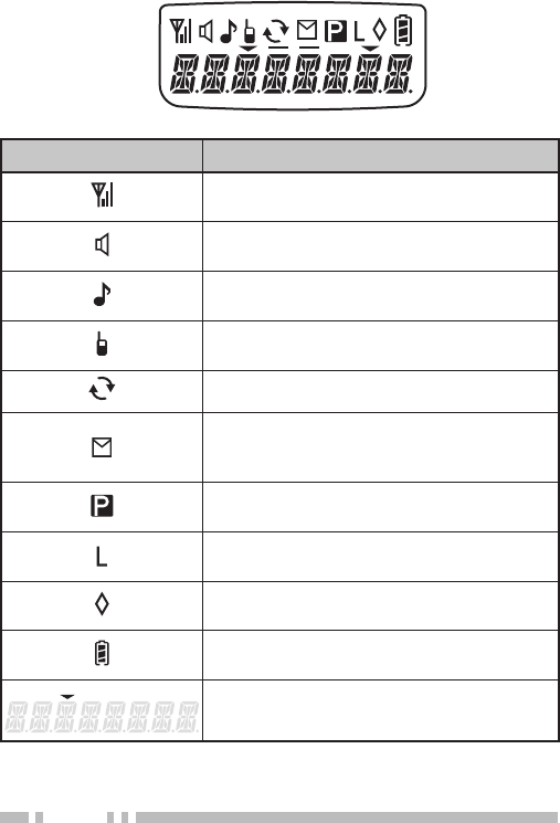
The battery power indicator displays the battery power
remaining, as illustrated below.
High Sufficient Low Very Low
(flashing)
When the battery power is very low, replace or recharge the
battery pack. If activated by your dealer, an alert tone will
sound every 30 seconds and the LED indicator will blink red
when the battery power is low while transmitting.
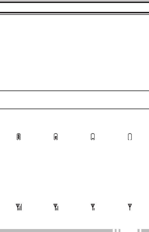
The signal strength indicator displays the strength of received
calls, as illustrated below.
Strong Medium Weak Very Weak

26
If BCL is set up by your dealer, you will be unable to transmit if
the channel is already in use. Use a different channel or wait
until the channel becomes free.
If programmed by your dealer for a channel, the compander
will remove excessive noise from transmitted signals, to
provide higher clarity of signals.
PTT ID is the transceiver unique ID code which is sent each
time the PTT switch is pressed and/or released.


Radio FRequency eneRgy SaFety inFoRmation
This Kenwood transceiver has been tested and complies with the standards listed below, in regards
to Radio Frequency (RF) energy and electromagnetic energy (EME) generated by the transceiver.
• FCC RF exposure limits for
Occupational Use Only
. RF Exposure limits adopted by the FCC are generally
based on recommendations from the National Council on Radiation Protection and Measurements, & the
American National Standards Institute.
• FCC OET Bulletin 65 Edition 97-01 Supplement C
• American National Standards Institute (C95.1 – 1992)
• American National Standards Institute (C95.3 – 1992)
This Kenwood transceiver generates RF EME while transmitting. RF EME (Radio Frequency Electric &
Magnetic Energy) has the potential to cause slight thermal, or heating effects to any part of your body less
than the recommended distance from this radio transmitter’s antenna. RF energy exposure is determined
primarily by the distance to and the power of the transmitting device. In general, RF exposure is minimized
when the lowest possible power is used or transmission time is kept to the minimum required for consistent
communications, and the greatest distance possible from the antenna to the body is maintained. The
transceiver has been designed for and is classied for
Occupational Use Only
. Occupational/ controlled
exposure limits are applicable to situations in which persons are exposed to RF energy as a consequence
of their employment, and such persons have been made aware of the potential for exposure and can
exercise control over their exposure. This means you can use the transceiver only if you are aware of
the potential hazards of operating a transceiver and are familiar in ways to minimize these hazards. This
transceiver is not intended for use by the general public in uncontrolled environments. Uncontrolled
environment exposure limits are applicable to situations in which the general public may be exposed to RF
energy, or in which the persons who are exposed as a consequence of their employment may not be fully
aware of the potential for exposure or cannot exercise control over their exposure.
The following list provides you with the information required to ensure that you are aware of RF
exposure and of how to operate this transceiver so that the FCC RF exposure limitations are not
exceeded.
• While transmitting (holding the PTT switch or speaking with VOX enabled), always keep the antenna
and the radio at least 3 cm (1 3/16 inches) from your body or face, as well as from any bystanders. A
LED on the top of the radio shows red when the transmitter is operating in both PTT and VOX modes.
• Do not transmit for more than 50% of the total transceiver use time; transmitting over 50% of the total use
time may exceed the limits in accordance to the FCC RF exposure requirements. Nominal transceiver
operation is 5% transmission time, 5% reception time, and 90% stand-by time.
• Use only the specied antenna for this transceiver; this may be either the antenna provided with the
transceiver or another antenna authorized by Kenwood.
Use only Kenwood authorized accessories (antennas, battery packs, belt clips, Speaker/ Mics or
headsets etc.): When worn on the body, always place the radio in a Kenwood recommended clip or
carrying case meant for this product. The use of other than recommended or approved body- worn
accessories may result in RF exposure levels which exceed the FCC’s occupational/ controlled
environment RF exposure limits.
To ensure that your exposure to RF EME is within the FCC limits for occupational use, you must
observe and adhere to the above points.
Electromagnetic Interference Compatibility
Electronic devices are susceptible to electromagnetic interference (EMI) if they are not adequately
shielded or designed for electromagnetic compatibility. Because this transceiver generates RF
energy, it can cause interference to such equipment.
• Turn OFF your transceiver where signs are posted to do so. Hospitals and health care facilities use
equipment that is sensitive to electromagnetic radiation.
• Turn OFF your transceiver while on board an aircraft when so instructed. Use of the transceiver must
be in accordance with airline regulations and/or crew instructions. B59-2546-00