Kenwood USA 413800 UHF FM Transceiver User Manual TK 3312 1 TK 3317 1 Instruction Manual
Kenwood USA Corporation UHF FM Transceiver TK 3312 1 TK 3317 1 Instruction Manual
UserManual.wiki
>
Kenwood USA
>
413800 User Manual
TK-3312-1,TK-3317-1 Instruction Manual
Navigation menu
Upload a User Manual
Namespaces
Wiki Guide
HTML
PDF
Info
Views
User Manual
Discussion / Help
Navigation
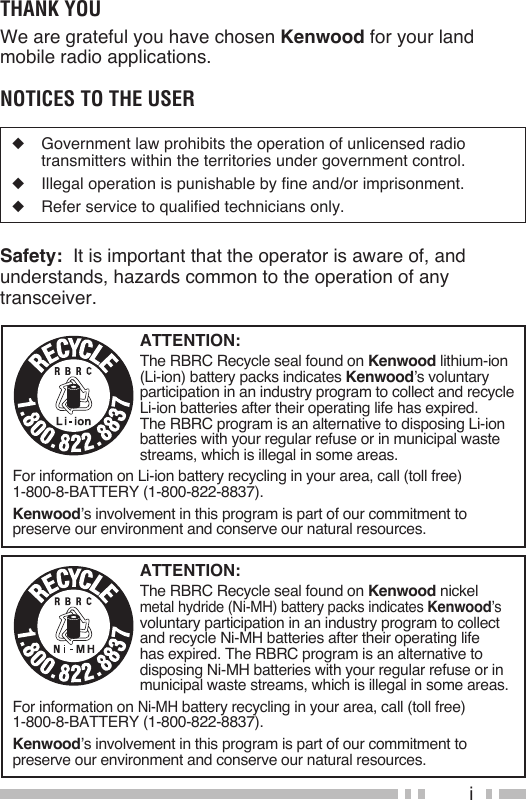
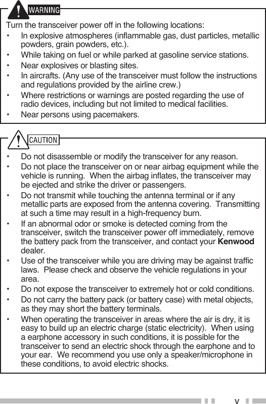
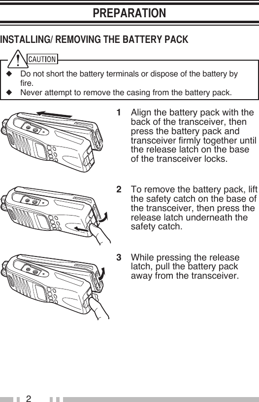
![6Battery pack Selector Rotate to change the operating zone or channel. The default setting is [Zone Up/ Down]. LED indicator Refer to the table on page 7 for the LED indicator status. Power switch/ Volume control Turn clockwise to switch the transceiver ON. To switch the transceiver OFF, turn counterclockwise until a click sounds. Rotate to adjust the volume level. PTT (Push to Talk) switch Press and hold, then speak into the microphone to transmit. Side 1 key Press to activate its programmable function. The default setting is [Squelch Off Momentary].Antenna SpeakerMicrophone](https://usermanual.wiki/Kenwood-USA/413800/User-Guide-1382893-Page-18.png)
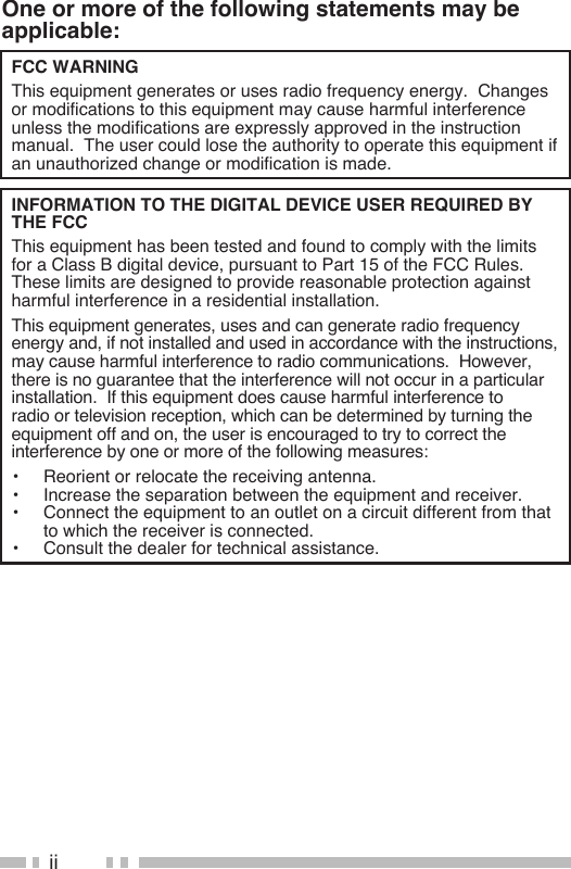
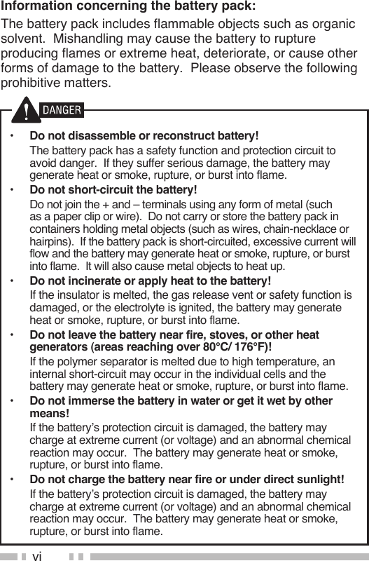
![7 Side 2 key Press to activate its programmable function. The default setting is [None] (no function). S, A, <B, C> keys Press to activate their programmable functions. S key: The default setting is [None] (no function). A key: The default setting is [None] (no function). <B key: The default setting is [Channel Down]. C> key: The default setting is [Channel Up]. , , keys Press to activate their programmable functions. The default setting is [None] (no function). Speaker/ Microphone jacks Insert the Speaker/ Microphone or Headset plug into this jack.LED Indicator StatusIndicator Color MeaningLights red TransmittingLights green Receiving a callLights orange While VOX level setupBlinks red Battery power is low while transmittingBlinks green ScanningBlinks orange* Receiving an encoded call (FleetSync, DTMF signaling, etc.)* Your dealer can change this setting to blue, instead of orange, for FleetSync operation.](https://usermanual.wiki/Kenwood-USA/413800/User-Guide-1382893-Page-19.png)
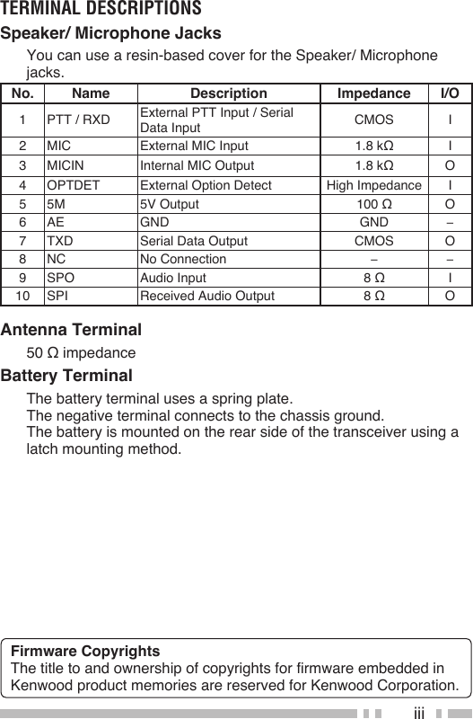
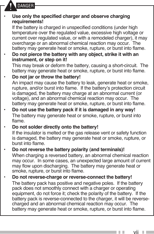
![10The Side 1, Side 2, S, A, <B, C>, , , and keys can be programmed with the functions listed below. Please contact your dealer for further details on these functions.Note: The Selector can be programmed as either [Zone Up/Down] or [Channel Up/Down].• None (No function)• 2-tone• Autodial• Call 1• Call 2• Channel Down• Channel Up• Calling Alert• Direct Zone Channel• Display Character• Emergency• Key Lock• Lamp• Lone Worker• Low Transmit Power• Monitor• Monitor Momentary• Operator Selectable Tone (OST)• Scan• Scan Del/Add• Scrambler• Selcall• Selcall+Status• Squelch Off• Squelch Off Momentary• Squelch Level• Status• Talk Around• Status• VOX• Zone Down• Zone Up](https://usermanual.wiki/Kenwood-USA/413800/User-Guide-1382893-Page-22.png)
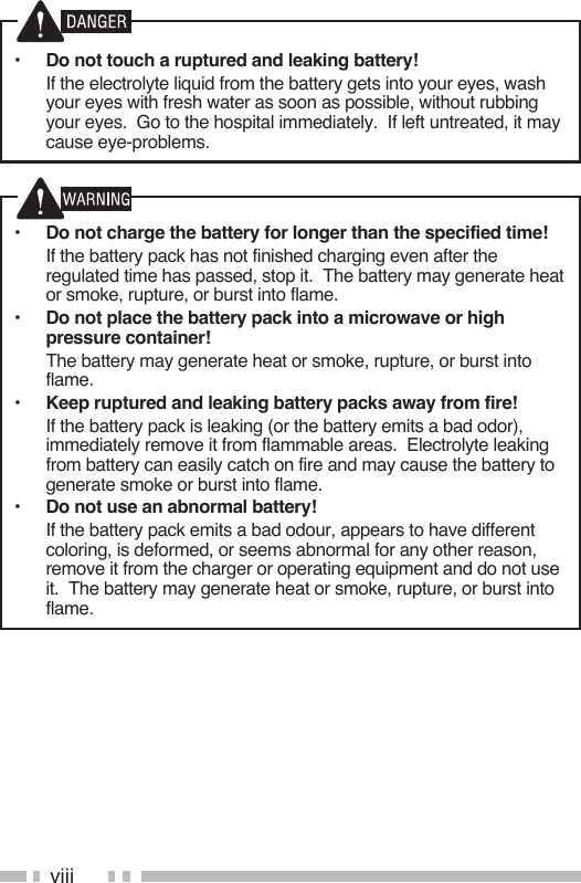
![11Turn the Power switch/ Volume control clockwise to switch the transceiver ON.• A beep sounds and the display momentarily lights up.• If the Transceiver Password function is programmed, “PASSWORD” appears on the display. Enter the password to unlock the transceiver (refer to “Transceiver Password”, below).Turn the Power switch/ Volume control counterclockwise to switch the transceiver OFF.■ If your transceiver is password protected, you must first enter the password before you can use the transceiver.1 Rotate the Selector to select the first digit of the password.2 Press C> to accept the entry and move to the next digit.• Press A to delete an incorrect digit. Press and hold A to delete all entered digits.3 Repeat steps 1 and 2 to enter the entire password.• The password can contain a maximum of 6 digits.4 Press S to confirm the entered password.• If you enter an incorrect password, an error tone sounds and the transceiver remains locked.Rotate the Power switch/ Volume control to adjust the volume. Clockwise increases the volume and counterclockwise decreases it.• You may need to adjust the volume more precisely while communicating with other parties.Note: If your dealer programmed [Squelch Off] or [Squelch Off Momentary] onto a PF key, you can use that key to hear background noise while adjusting the volume level.](https://usermanual.wiki/Kenwood-USA/413800/User-Guide-1382893-Page-23.png)
![12Select the desired zone using the Selector or the keys programmed as [Zone Up]/ [Zone Down].• The default setting for the Selector is [Zone Up/ Down].Select the desired channel using the Selector or the keys programmed as [Channel Up]/ [Channel Down].• The default setting for the <B key is [Channel Down].• The default setting for the C> key is [Channel Up].Names can be programmed for channels, with up to 8 characters each. The transceiver will display either the channel name or the zone and channel number. Press the key programmed as [Display Character] to toggle between the two displays.1 Select your desired zone and channel using the Selector and the [Zone] or [Channel] keys.2 Press the key programmed as [Monitor] or [Squelch Off] to check whether or not the channel is free.• If the channel is busy, wait until it becomes free.3 Press the PTT switch and speak into the microphone in your normal speaking voice.• For best sound quality at the receiving station, hold the microphone approximately 1.5 inches (3 ~ 4 cm) from your mouth.4 Release the PTT switch to receive.1 Select your desired zone and channel using the Selector and the [Zone] or [Channel] keys.• Alternatively, you can turn the Scan function on if desired.2 When you hear a caller’s voice, readjust the volume as necessary.](https://usermanual.wiki/Kenwood-USA/413800/User-Guide-1382893-Page-24.png)
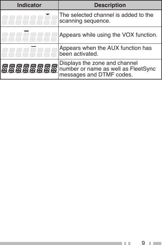
![13Scan monitors for signals on the transceiver channels. While scanning, the transceiver checks for a signal on each channel and only stops if a matching signal is present.To start/stop scanning, press the key programmed as [Scan].• The indicator appears during Scan.• When a signal is detected, Scan pauses at that channel. The transceiver will remain on the busy channel until the signal is no longer present, at which time Scan resumes.Note: To use Scan, there must be at least 2 channels added to the scanning sequence.If a Priority channel has been programmed, the transceiver will automatically change to the Priority channel when a call is received on that channel, even if call is being received on a normal channel.• The indicator appears when the selected channel is the Priority channel (depending on dealer setting).During scan, you can temporarily remove specific channels from the scanning sequence by momentarily pressing the key programmed as [Scan Del/Add] while Scan is paused at the undesired channel. To temporarily remove a zone, press and hold the [Scan Del/Add] key while Scan is paused at a channel in the undesired zone.• The channel/zone is no longer scanned. However, when scanning is ended and restarted, the Scan settings return to normal.](https://usermanual.wiki/Kenwood-USA/413800/User-Guide-1382893-Page-25.png)
![14You can add and remove zones and/or channels to and from your scan list.1 Select your desired zone and/or channel.2 Press the key programmed as [Scan Delete/Add] to remove a channel or press and hold the key for approximately 1 second to remove a zone.• The channel add indicator ( ) appears when the selected channel is added to the scan sequence.• The zone add indicator ( ) appears when the selected zone is added to the scan sequence.The Scan Revert channel is the channel selected when you press the PTT switch to transmit during scan. Your dealer can program one of the following types of Scan Revert channels:• Selected: The last channel selected before scan.• Selected + Talkback: Same as “Selected”, plus you can respond to calls on the channel at which scan is paused.• Priority: The Priority channel.• Priority + Talkback: Same as “Priority”, plus you can respond to calls on the channel at which scan is paused.• Last Called + Selected: The last channel on which you receive a call. If you have not yet received a call, then the last channel selected before scan.](https://usermanual.wiki/Kenwood-USA/413800/User-Guide-1382893-Page-26.png)
![15Autodial allows you to quickly call DTMF numbers that have been programmed onto your transceiver.1 Press the key programmed as [Autodial].• The last called number appears.2 Press <B or C> to select your desired Autodial list number.3 Press the PTT switch to make the call.• Press S to exit without making a call.This function is used when a transceiver is stolen or lost. When the transceiver receives a call containing a stun code, the transceiver becomes disabled. The stun code is cancelled when the transceiver receives a call with a revive code.• “STUN” appears while the transceiver is stunned.Note: This features can only be activated when DTMF Signaling is turned OFF.When you receive a DTMF code containing at least 3 digits, it will appear on the display. Each successive digit will continue to scroll across the display, as long as each digit is received within 1 second of the previous digit. If no digit is received for more than 1 second, then when a new digit is received, the display will clear and begin with the new digit.Press any key to cancel the DTMF number display.](https://usermanual.wiki/Kenwood-USA/413800/User-Guide-1382893-Page-27.png)
![16Your dealer may have programmed QT or DQT signaling on your transceiver channels. QT and DQT signals allow you to ignore (not hear) calls from other parties who are using the same channel.Your dealer may also program several types of optional signaling for your transceiver channels.2-tone Signaling: 2-tone Signaling opens the squelch only when your transceiver receives a call containing matching 2 tones.DTMF Signaling: DTMF Signaling opens the squelch only when the transceiver receives a call containing a matching DTMF code.FleetSync Signaling: Refer to “Selcall (Selective calling)” on page 17.MDC-1200: MDC-1200 is a data system using Audio Frequency Shift Keying (AFSK).You can change the preset encode and decode tones for the selected channel. Up to 40 OST pairs can be pre-programmed by your dealer.1 Select your desired channel.2 Press the key programmed as [Operator Selectable Tone (OST)] to enter OST Select Mode.• “OST” and the current OST number appear.3 Press <B or C> to select the desired OST table number.4 Use the transceiver the same as in a regular call; press the PTT switch to transmit and release it to receive.5 To exit OST mode and return to the preset encode and decode tones, press S.](https://usermanual.wiki/Kenwood-USA/413800/User-Guide-1382893-Page-28.png)
![17FleetSync is an Alphanumeric 2-way Paging Function and is a protocol owned by Kenwood Corporation.Note: If set up by your dealer, your transceiver may use the MDC-1200 feature in place of FleetSync. MDC-1200 and FleetSync cannot be operated simultaneously.A Selcall is a voice call to a particular station or to a group of stations.■ 1 Select your desired zone and channel.2 Press the key programmed as [Selcall] or [Selcall + Status] to enter Selcall mode.• The last selected station ID appears on the display.3 Press <B or C> to select the ID of the station you want to call.4 Press the PTT switch and begin your conversation.• Alternatively, you can press the Side 2 key to page the selected station, rather than making a voice call.■ An alert tone will sound, the transceiver will automatically enter Selcall Mode, and the calling station’s ID will appear when a Selcall is received. To respond to the call, press the PTT switch and speak into the microphone.■ An ID code is a combination of a 3-digit Fleet number and a 4-digit ID number. Each transceiver must have its own Fleet and ID number.Note: The ID range may be limited by programming.](https://usermanual.wiki/Kenwood-USA/413800/User-Guide-1382893-Page-29.png)
![18You can transmit pre-programmed status messages by pressing the keys programmed as [Status] and [Selcall + Status].Status messages are 2-digit codes ranging from 10 to 99 (80 ~ 99 are reserved for special messages).■ 1 Select your desired zone and channel.2 Press the key programmed as [Status] to enter Status mode or [Selcall + Status] to enter Selcall mode.• When using the Status key to enter Status mode, the target Fleet/ ID is fixed and cannot be selected. Skip to step 5 to continue.3 In Selcall mode, press <B or C> to select the ID of the station you want to call.4 Press S to enter Status Mode.5 Press <B or C> keys to select the status ID you want to transmit.6 Press the PTT switch or Side 2 key to initiate the Status call.• “COMPLETE” appears when the call has been successfully transmitted.■ The indicator will flash and a calling ID or text message will appear when a Status call is received. Press any key to return to normal operation.](https://usermanual.wiki/Kenwood-USA/413800/User-Guide-1382893-Page-30.png)
![19■ 1 Press and hold the key programmed as [Selcall], [Status], or [Selcall + Status] for 1 second to enter the Stack memory.• The last received message is displayed with the message number.2 Press <B or C> to select the desired message.• Press and hold S to toggle between the call ID/ message and the channel name.3 Press the Side 1 key to return to normal operation.• To delete the selected message, press A. To confirm the deletion, press S.• To delete all messages, press and hold A for 1 second. To confirm the deletion, press S.This transceiver can receive short data messages which contain a maximum of 48 characters.• Received short messages are displayed the same as Status messages. A maximum of 3 short message can be stored in the stack memory, along with 5 Status messages.](https://usermanual.wiki/Kenwood-USA/413800/User-Guide-1382893-Page-31.png)
![20VOX operation allows you to transmit hands-free. This feature can be activated or deactivated by your dealer.1 If the VOX function is not ON, press and hold the key programmed as [VOX] for 2 seconds.• The VOX indicator ( ) appears when the VOX function is ON.2 Connect a headset to the transceiver.3 To transmit, simply speak into the microphone.• The transceiver recognizes sound levels depending on the VOX Gain level. 4 When you finish speaking, transmission ends.1 Press the key programmed as [VOX] when the VOX function is not ON.• The current VOX Gain level appears on the display.2 Press <B or C> to select your desired VOX Gain level.• The VOX Gain can be adjusted from levels 1 (low sensitivity) to 10 (high sensitivity), and off. The default setting is level 5.3 While adjusting the level, speak into the headset microphone to test the sensitivity level. (Your voice is not transmitted during this test procedure.)• If the VOX Gain is too sensitive, transmission will occur when there is noise in the background. If it is not sensitive enough, it will not pick up your voice when you begin speaking.4 Press S to save the setting.](https://usermanual.wiki/Kenwood-USA/413800/User-Guide-1382893-Page-32.png)
![21Each channel is programmed with either high or low transmit power. On high transmit power channels, press the key programmed as [Low Transmit Power] to change the transmit power to low power (you cannot change low transmit power channels to use high power).• The indicator appears while using low transmit power.The Calling Alert tone alerts party members that you are making a call. To make a call:1 Briefly press and hold the key programmed as [Calling Alert].• Release the key to end the tone transmission.2 Press the PTT switch and speak into the microphone in your normal speaking voice.Press and hold the key programmed as [Key Lock] for 2 seconds to lock the transceiver keys. Press and hold the [Key Lock] key again to unlock the keys.• “LOCKED” appears when a key is pressed while the keys are locked.Note: You can still use the following keys and functions when Key Lock is activated: [Emergency], [Monitor], [Monitor Momentary], [Squelch Off], [Squelch Off Momentary], [Key Lock], PTT.](https://usermanual.wiki/Kenwood-USA/413800/User-Guide-1382893-Page-33.png)
![22If your transceiver has been programmed with the Emergency function, you can make emergency calls.1 Press and hold the key programmed as [Emergency].• Depending on the delay time programmed into your transceiver, the length of time you must hold the Emergency key will vary.• When the transceiver enters Emergency mode, the transceiver will change to the Emergency channel and begin transmitting based on how the transceiver is set up.2 To exit Emergency mode, press and hold the [Emergency] key again.• If the Emergency mode completes the preset number of cycles, Emergency mode will automatically end and the transceiver will return to normal.■ Lone Worker Mode is a safety feature built into the transceiver. If the transceiver is not operated for a pre-programmed period of time, the transceiver will emit a tone and automatically enter Emergency operation. Press and hold the key programmed as [Lone Worker] for 2 seconds to toggle the Lone Worker function ON or OFF.During interruptions in service (such as a power failure), you can continue to communicate by using the Talk Around feature. Talk Around allows you to communicate directly with other transceivers without the use of a repeater, as long they are not too far away or there are no geographical obstacles in the way.Press the key programmed as [Talk Around] to toggle the Talk Around function ON or OFF.• The indicator appears while Talk Around is activated.](https://usermanual.wiki/Kenwood-USA/413800/User-Guide-1382893-Page-34.png)
![23The scrambler prevent others from easily listening in on your calls. When activated, the transceiver distorts your voice so that anybody listening to your conversation will not be able to clearly hear what you are saying.In order for members of your own group to hear your call while you are using the scrambler, all members must activate their scrambler functions.Press the key programmed as [Scrambler] to toggle the Scrambler function ON or OFF.• The indicator appears while the Scrambler is activated.If necessary, you can change your transceiver scrambler code:1 Press and hold the key programmed as [Scrambler] for 1 second.• The indicator and current scrambler code appear.2 Press <B or C> to select your desired scrambler code.3 Press S to store the new setting.• After changing your scrambler code, be sure to inform all of your group members of the new code so they can also reset their transceivers. The scrambler function will not work with transceivers set up with different scrambler codes.Note: This function cannot be used in certain countries. Contact your Kenwood dealer for further information.](https://usermanual.wiki/Kenwood-USA/413800/User-Guide-1382893-Page-35.png)
![24You can use the key programmed as [Monitor] or [Squelch Off] to listen to weak signals that you cannot hear during normal operation and to adjust the volume when no signals are present on your selected channel.Your dealer can program a key with one of 4 functions:• Monitor: Press to deactivate all signaling. Press again to return to normal operation.• Monitor Momentary: Press and hold to deactivate all signaling. Release to return to normal operation.• Squelch Off: Press to hear background noise. Press again to return to normal operation.• Squelch Off Momentary: Press and hold to hear background noise. Release to return to normal operation.■ If a key has been programmed as [Squelch Level], you can readjust your transceiver’s squelch level.1 Press the key programmed as [Squelch Level].• “SQL.LEV.” and the current squelch level appear.2 Press <B or C> to select the desired squelch level from 0 (open) to 9 (tight).3 Press S to store the new setting.To turn the transceiver display and front panel key backlight on, press the key programmed as [Lamp].• The display and keypad remain lit for 5 seconds. Pressing any key other than the PTT switch and the Power switch/ Volume control while the backlight is on will reset the timer to 5 seconds.To turn the transceiver backlight off immediately, press the Lamp key while the backlight is on.Press the key programmed as [Direct Zone Channel] to immediately select the lowest channel of the lowest zone.](https://usermanual.wiki/Kenwood-USA/413800/User-Guide-1382893-Page-36.png)