Kenwood USA 430900 VHF Digital Transceiver User Manual NX 220 Instruction Manual
Kenwood USA Corporation VHF Digital Transceiver NX 220 Instruction Manual
UserManual.wiki
>
Kenwood USA
>
430900 User Manual
NX-220 Instruction Manual
Navigation menu
Upload a User Manual
Namespaces
Wiki Guide
HTML
PDF
Info
Views
User Manual
Discussion / Help
Navigation
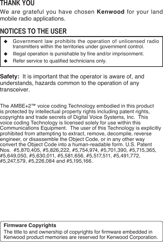

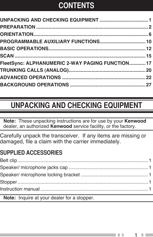
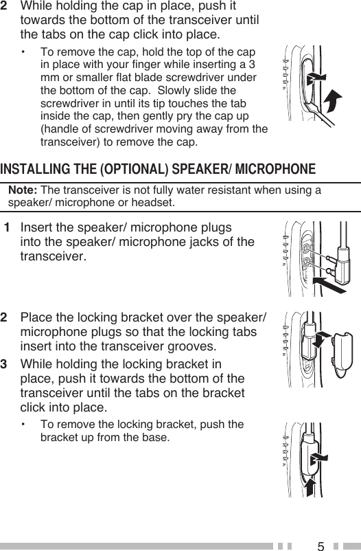
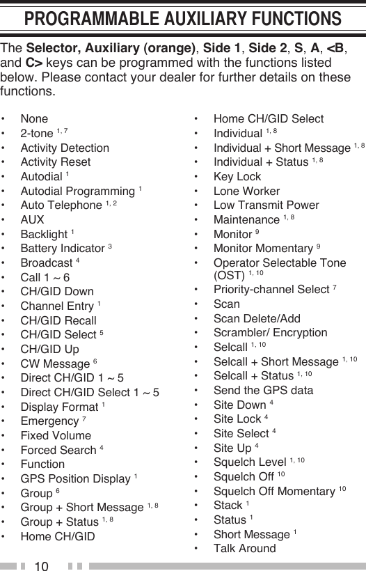
![8 Side 2 key Press to activate its programmable function {page 10}. The default is Backlight. S, A, <B, C> key <Type I, II> Press to activate its programmable function {page 10}. S key: The default setting is [None] (no function). A key: The default setting is [None] (no function). <B key: The default setting is [Channel Down]. C> key: The default setting is [Channel Up]. Keypad <Type I> Press these keys to send DTMF tones. These keys can also be programmed with secondary functions {page 10} if a programmable function key is programmed as “Function”. Speaker/ Microphone jacks Insert the Speaker/ Microphone or Headset plug into this jack.](https://usermanual.wiki/Kenwood-USA/430900/User-Guide-1420029-Page-19.png)
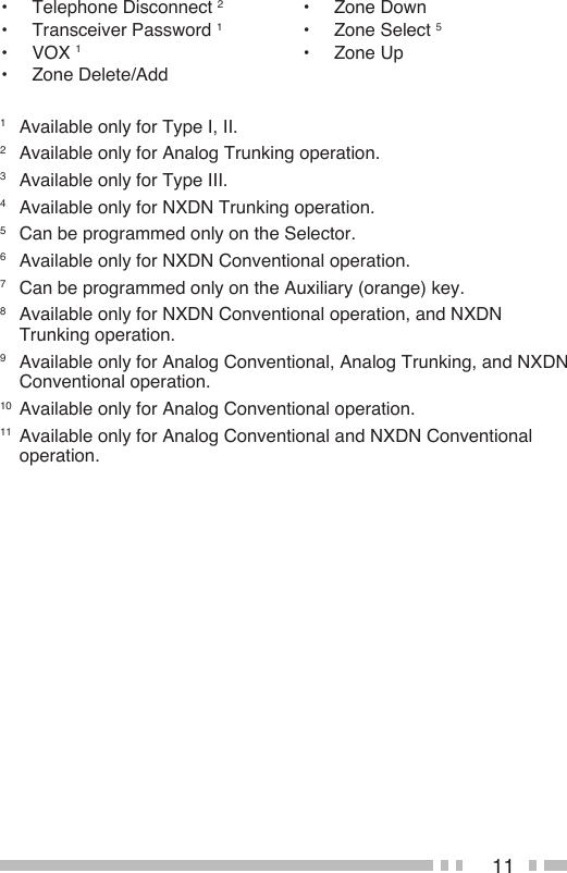
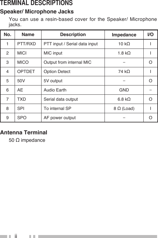
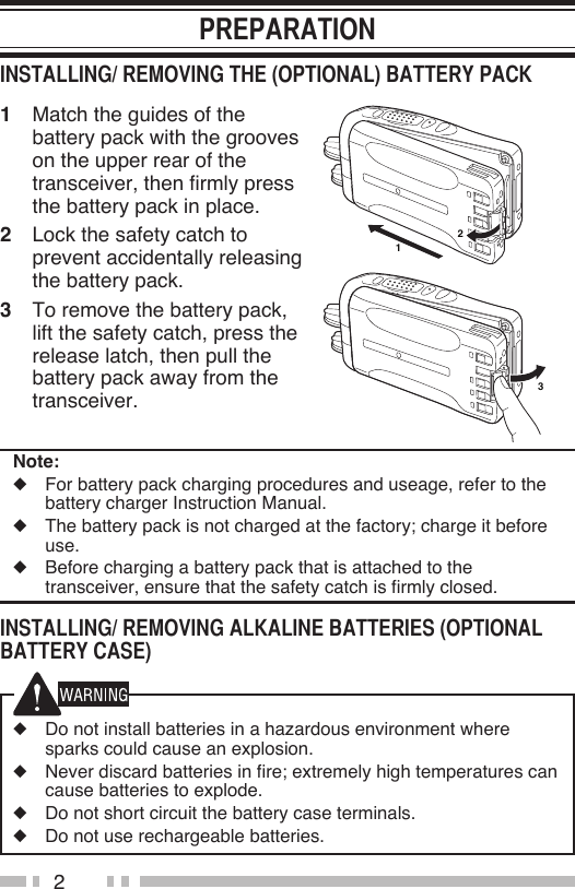
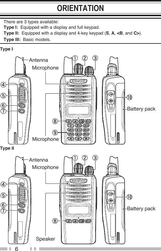
![12Turn the Power switch/ Volume control clockwise to switch the transceiver ON.Turn the Power switch/ Volume control counterclockwise fully to switch the transceiver OFF.■ If your transceiver is password protected, you must first enter the password before you can use the transceiver.1 Rotate the Selector to select the first digit of the password.2 Press the C> key to accept the entry and move to the next digit.• Press the A or # key to delete an incorrect digit.3 Repeat steps 1 and 2 to enter the entire password.• The password can contain a maximum of 6 digits.4 Press the S or key to confirm the entered password.• If you enter an incorrect password, an error tone sounds and the transceiver remains locked.Rotate the Power switch/ Volume control to adjust the volume. Clockwise increases the volume and counterclockwise decreases it. Select the desired zone using the key programmed as [Zone Select] or [Zone Up/Down]. Each zone contains a group of channels.Select the desired channel/group ID using the Selector knob (default). Each channel/group ID is programmed with settings for transmitting and receiving.](https://usermanual.wiki/Kenwood-USA/430900/User-Guide-1420029-Page-23.png)
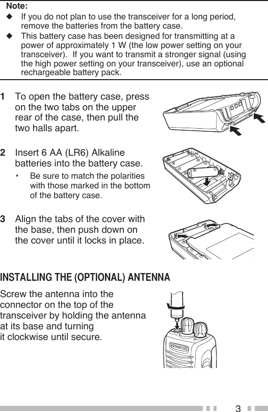
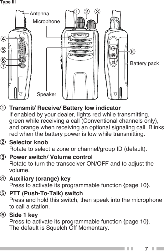
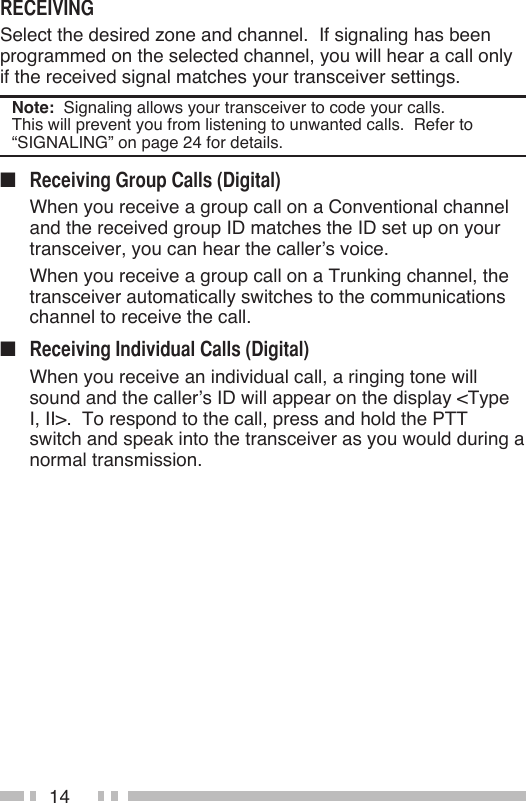
![131 Select the desired zone and channel/group ID.2 Press the key programmed as [Monitor] or [Squelch Off] to check whether or not the channel is free.• If the channel is busy, wait until it becomes free.3 Press the PTT switch and speak into the microphone. Release the PTT switch to receive.• For best sound quality, hold the transceiver approximately 1.5 inches (3 ~ 4 cm) from your mouth.■ If a key has been programmed with [Group] or [Group + Status], you can select a group ID from the list to make a call to those parties on a Conventional channel. To select a group ID:1 Press the key programmed as [Group] or [Group + Status].2 Press the <B or C> key programmed to select a group ID/name from the list.3 Press and hold the PTT switch to make the call.• Speak into the transceiver as you would during a normal transmission.■ If a key has been programmed with [Individual] or [Individual + Status], you can make calls to specific persons.1 Press the key programmed as [Individual] or [Individual + Status].2 Press the <B or C> to select a unit ID from the list.• On Type I, you can enter a unit ID directly.3 Press and hold the PTT switch to make the call.• Speak into the transceiver as you would during a normal transmission.](https://usermanual.wiki/Kenwood-USA/430900/User-Guide-1420029-Page-24.png)
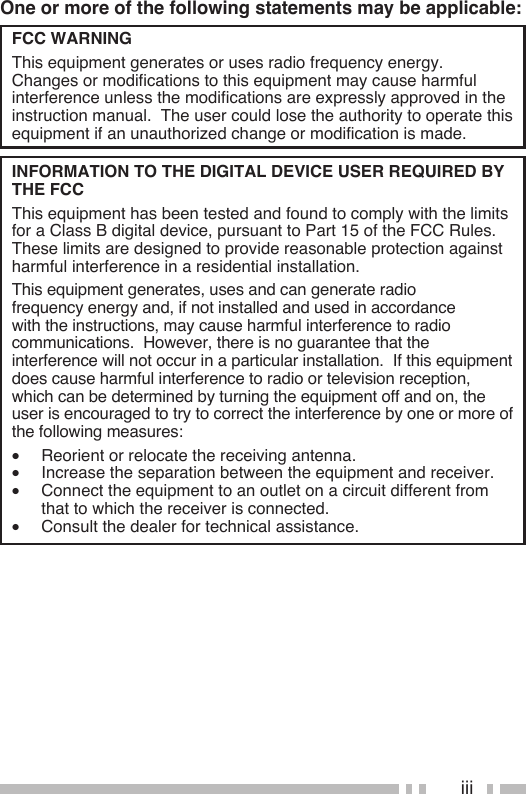
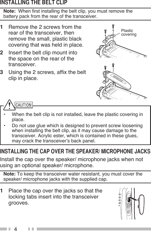
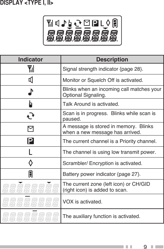
![15Scan monitors for signals on the transceiver channels. While scanning, the transceiver checks for a signal on each channel and only stops if a signal is present.To begin scanning, press the key programmed as [Scan].• The indicator on the display <Type I, II>.• The LED blinks green.• When a signal is detected on a channel, Scan pauses at that channel. The transceiver will remain on the busy channel until the signal is no longer present, at which time Scan resumes.To stop scanning, press the [Scan] key again.Note: To use Scan, there must be at least 2 channels in the scan sequence.During scan, you can temporarily remove specific channels from the scanning sequence by selecting them and pressing the key programmed as [Scan Delete/Add].• The channel is no longer scanned. However, when scanning is ended and restarted, the channels are reset and deleted channels will again be in the scanning sequence.If a Priority channel has been programmed, the transceiver will automatically change to the Priority channel when a call is received on that channel, even if call is being received on a normal channel.• The indicator appears when the selected channel is the Priority channel (depending on dealer setting) <Type I, II>.](https://usermanual.wiki/Kenwood-USA/430900/User-Guide-1420029-Page-26.png)
![16The Scan Revert channel is the channel selected when you press the PTT switch to transmit during scan. Your dealer can program one of the following types of Scan Revert channels:• Selected: The last channel selected before scan.• Selected + Talkback: Same as “Selected”, plus you can respond to calls on the channel at which scan is paused.• Priority: The Priority channel.• Priority + Talkback: Same as “Priority”, plus you can respond to calls on the channel at which scan is paused.• Last Called + Selected: The last channel on which you receive a call. You can add and remove zones and/or channels/group IDs to and from your scan list.1 Select your desired zone and/or channel/group ID.2 Press the key programmed as [Zone Delete/Add] (to add/remove zones) or [Scan Delete/Add] (to add/remove channels/group IDs) <Type I, II>.• You can also press and hold the key programmed as [Scan Delete/Add] to add/remove zones.](https://usermanual.wiki/Kenwood-USA/430900/User-Guide-1420029-Page-27.png)
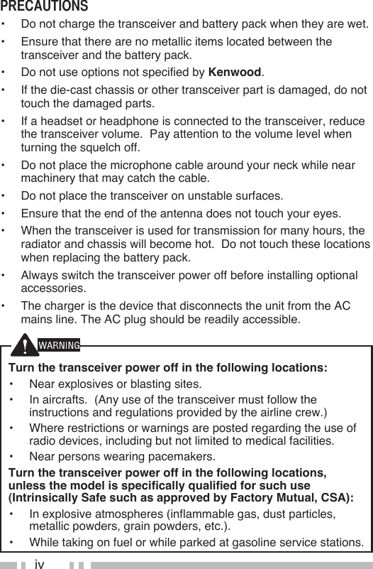
![17FleetSync is an Alphanumeric 2-way Paging Function, and is a protocol owned by Kenwood Corporation.Note: This function is available only in analog operation. A Selcall is a voice call to a station or group of stations.■ 1 Select your desired zone and channel.2 Press the key programmed as [Selcall] or [Selcall + Status] to enter Selcall mode.3 Press the <B or C> key to select the station you want to call.• On keypad models, if Manual Dialing is enabled, you can directly enter the station ID.4 Press the PTT switch and begin your conversation.■ An alert tone will sound and the transceiver will enter Selcall mode. The calling station’s ID will appear when a Selcall is received <Type I, II>. You can respond to the call by pressing the PTT switch and speaking into the microphone.■ An ID code is a combination of a 3-digit Fleet number and a 4-digit ID number. Each transceiver has its own ID.• Enter a Fleet number (100 ~ 349) to make a group call.• Enter an ID number (1000 ~ 4999) to make an individual call in your fleet.• Enter a Fleet number to make a call to all units in the selected fleet (Fleet call).• Enter an ID number to make a call to the selected ID in all fleets (Supervisor call).](https://usermanual.wiki/Kenwood-USA/430900/User-Guide-1420029-Page-28.png)
![18• Select “ALL” Fleet and “ALL” ID to make a call to all units (Broadcast call). You can send and receive 2-digit Status messages which may be decided in your talk group. Messages can contain up to 16 alphanumeric characters. Status messages range from 10 to 99 (80 ~ 99 are reserved for special messages). A maximum of 15 received messages (combined status messages and short messages) can be stored in the stack memory of your transceiver.■ 1 Select your desired zone and channel.2 Press the key programmed as [Status] to enter Status mode (proceed to step 5) or [Selcall + Status] to enter Selcall mode (proceed to step 3).3 Press the <B or C> key to select the station you want to call.• If Manual Dialing is enabled, you can enter a station ID by using the DTMF keypad, or by using the <B or C> key. When using the <B or C> key, cycle through the digits to select a digit, then press the S key to set the digit and move the cursor to the right. Repeat this process until the entire ID is entered.4 Press the S key to enter Status mode.5 Press the <B or C> key to select the status you want to transmit.• If Manual Dialing is enabled, you can enter a status ID by using the DTMF keypad, or by using the <B or C> key (refer to step 3, above).6 Press the PTT switch or Side 2 key to initiate the call.• “COMPLETE” appears on the display when the status has been successfully transmitted.](https://usermanual.wiki/Kenwood-USA/430900/User-Guide-1420029-Page-29.png)
![19■ A calling ID or text message will appear when a Status call is received. Press any key to return to normal operation.■1 Press the key programmed as [Stack], or press and hold the key programmed as [Selcall], [Status], or [Selcall + Status] to enter Stack mode.• The last received message is displayed.2 Press the <B or C> key to select the desired message.• Message types are identified as follows: I: Caller ID, S: Status Message, M: Short Message• Press and hold the S key for 1 second to cycle the display information as follows: ID Name > Status/Short Message > CH/GID > Time Stamp 3 Press the Side 1 key to return to normal operation.• To delete the selected message, press the A key. To confirm the deletion, Press the S key.• To delete all messages, press and hold the A or # key for 1 second. To confirm the deletion, Press the S or key. Received short messages are displayed the same as Status messages and are stored in the same stack memory (Type I, II). To send short messages, and to send and receive long messages, you must connect the transceiver to a PC. Ask your dealer for details.To send your location data, you must first connect a GPS unit to the transceiver. GPS data can be manually transmitted by pressing the key programmed as [Send the GPS data]. If set up by your dealer, GPS data may be automatically transmitted at a preset time interval.](https://usermanual.wiki/Kenwood-USA/430900/User-Guide-1420029-Page-30.png)
![201 Select the desired zone and group ID using the selector and the Zone or CH/GID keys.2 Press and hold the PTT switch.3 If the “PTT Proceed” tone sounds, communication is possible; start speaking into the microphone. Release the PTT switch to receive.• For best sound quality at the receiving station, hold the microphone approximately 1.5 inches (3 ~ 4 cm) from your mouth.• Your dealer can deactivate the Proceed PTT tone, if necessary. Ask your dealer for details.1 When a dispatch call is received, the transceiver will automatically change to the correct group ID and you will hear the call.2 Readjust the volume as necessary.1 Select the desired zone and group ID using the selector and the Zone or CH/GID keys.• Alternatively, you can press the key programmed as [Auto Telephone] to automatically search for a Telephone Repeater.2 Press and hold the PTT switch for approximately 1 second to ensure a connection.• Confirm that there is a dial tone after you release the PTT switch.3 Place the call, following the instructions for making a DTMF call, starting on page 22.](https://usermanual.wiki/Kenwood-USA/430900/User-Guide-1420029-Page-31.png)
![214 When the called party responds, press the PTT switch and speak into the microphone. Release the PTT switch to receive.• Only one person can speak at a time.5 To end the call, press and hold the PTT switch, then press the # key or the key programmed as [Telephone Disconnect].1 When a telephone call is received, the transceiver will automatically change to the correct group ID and you will hear the call.• A ringer tone will sound when a call is received.2 Press and hold the PTT switch to speak, and release it to receive.• Only one person can speak at a time.3 To end the call, press and hold the PTT switch, then press the # key or the key programmed as Telephone Disconnect.](https://usermanual.wiki/Kenwood-USA/430900/User-Guide-1420029-Page-32.png)
![22■ Manual Dialing <Type I>1 Press and hold the PTT switch.2 Enter the desired digits using the DTMF keypad.• If you release the PTT switch, transmit mode will end even if the complete number has not been sent.• If the Keypad Auto PTT function has been enabled by your dealer, you do not need to press the PTT switch to transmit; you can make the call simply pressing the DTMF keys.Store & Send1 Press the key programmed as [Autodial].2 Enter up to 30 digits using the DTMF keypad.• Alternatively, you can enter digits by using the <B or C> key .3 Press the PTT switch to make the call.■ Autodial allows you to quickly call DTMF numbers that have been programmed onto your transceiver.1 Press the key programmed as Autodial.• The first entry in the Autodial list appears on the display.2 Press the <B or C> key to select your desired Autodial list number, or enter the list number directly (01 ~ 32).• The stored entry appears on the display.3 Press the PTT switch to make the call.■ This function is used when a transceiver is stolen or lost. When the transceiver receives a call containing a stun](https://usermanual.wiki/Kenwood-USA/430900/User-Guide-1420029-Page-33.png)
![23code, the transceiver becomes disabled. The stun code is cancelled when the transceiver receives a call with a revive code.If your transceiver has been programmed with the Emergency function, you can make emergency calls.1 Press and hold the key programmed as [Emergency].• Ask your dealer for the length of time necessary to hold this key before the transceiver enters Emergency mode.• When the transceiver enters Emergency mode, it will change to the Emergency channel and begin transmitting based on how it is set up by your dealer.2 To exit Emergency mode, press the [Emergency] key again.• If the Emergency mode completes a preset number of cycles, Emergency mode will automatically end and the transceiver will return to the zone and channel that was in use before Emergency mode was entered.Note:◆ Your dealer can set the transceiver to emit a tone when transmitting in Emergency mode.◆ Your dealer can set the transceiver to emit tones and received signals as normal, or mute the speaker during Emergency operation.■ Press the key programmed as [Activity Detection], toggle Activity Detection ON and OFF. If an event occurs while Activity Detection is enabled, the transceiver enters Emergency mode.Note:◆ When Activity Detection has been turned off, and the transceiver power is then turned off and back on, Activity Detection is automatically enabled.◆ When using this function, verify that it operates before taking the transceiver.](https://usermanual.wiki/Kenwood-USA/430900/User-Guide-1420029-Page-34.png)
![24■ While Activity Detection is active, press the key programmed as [Activity Reset] to reset the Activity Detection countdown timer. This will allow you to remain in a tilted or stationary position, etc., without the Emergency mode activating unnecessarily.Press the key programmed as [Scrambler/ Encryption], to switch the transceiver to secure (encrypted) transmission.• Pressing the PTT switch after the Scrambler function has been turned ON encrypts the transmitted signal.■ Your dealer may have programmed QT or DQT signaling on your transceiver channels. A QT tone/ DQT code is a sub-audible tone/code which allows you to ignore (not hear) calls from other parties who are using the same channel. Operator Selectable Tone <Type I, II> If a key has been programmed with [OST], you can reprogram the QT/DQT settings on each of your channels.1 Select your desired channel.2 Press and hold the key programmed as [OST] for 1 second.3 Press the <B or C> key to select your desired tone or code.• Your dealer can set up to 40 tones/codes.4 Press the S key to save your new setting.5 When you have finished operating using OST, press the [OST key again to turn the OST function OFF.](https://usermanual.wiki/Kenwood-USA/430900/User-Guide-1420029-Page-35.png)
![25■ RAN is a new signaling system designed for digital radio communications. When a channel is set up with a RAN, squelch will only open when a call containing a matching RAN is received. If a call containing a different RAN is made on the same channel you are using, you will not hear the call. This allows you to ignore (not hear) calls from other parties who are using the same channel.■ Your dealer may also program several types of optional signaling for your transceiver channels. DTMF Signaling : DTMF Signaling opens the squelch only when the transceiver receives a call containing a matching DTMF code. FleetSync Signaling : Refer to “SELCALL (SELECTIVE CALLING)” on page 17. NXDN ID Signaling: NXDN ID is an optional signaling system available only for digital communications.VOX can be activated or deactivated by your dealer. VOX operation allows you to transmit hands-free.Note: To operate VOX, you must use an optional headset.■ 1 Connect the headset to the transceiver.2 Press the key programmed as [VOX].• The current VOX Gain level appears on the display.3 Press the <B or C> key to increase or decrease the VOX Gain level.• The VOX Gain can be adjusted from levels 1 to 10.](https://usermanual.wiki/Kenwood-USA/430900/User-Guide-1420029-Page-36.png)
![264 While adjusting the level, speak into the headset microphone to test the sensitivity level. (Your voice is not transmitted during this test procedure.)• When sound is recognized, the LED lights orange.5 Press the S key to save the setting.■ 1 Connect the headset to the transceiver.2 Press and hold the key programmed as [VOX] for 2 seconds.3 To transmit, simply speak into the microphone.• The transceiver recognizes sound levels depending on the VOX Gain level. If it is too sensitive, it will transmit when there is noise in the background. If it is not sensitive enough, it will not pick up your voice when you begin speaking.4 When you finish speaking, transmission ends.5 To turn the VOX function OFF, press and hold the [VOX] key again, for 2 seconds.Note: If a speaker/ microphone is connected to the transceiver while VOX is ON, and the VOX Gain Level is set to a sensitive level, louder received signals may cause the transceiver to transmit.](https://usermanual.wiki/Kenwood-USA/430900/User-Guide-1420029-Page-37.png)
![27Your dealer can activate a variety of transceiver functions to perform without any additional operation on your part.The Time-out Timer is used to prevent you from using a channel for an extended duration. If you continuously transmit for a preset time, the transceiver will stop transmitting and an alert tone will sound. Release the PTT switch.The Battery Saver can be activated only on Conventional channels. This function decreases the amount of power used when a signal is not being received and no operations are being performed.Press the key programmed as [Key Lock] to lock and unlock the transceiver keys.• The following keys still function when Key Lock is activated: Emergency, Backlight, Monitor, Monitor Momentary, Squelch Off, Squelch Off Momentary, Function, Key Lock, PTT.Your dealer can set an alert tone to sound and the LED indicator to blink red when the battery power is low. The battery power icon displays the battery power remaining, as described in the table below. When the battery power is very low, recharge or replace the battery pack.High Sufficient Low Very low](https://usermanual.wiki/Kenwood-USA/430900/User-Guide-1420029-Page-38.png)
![28Press the key programmed as [Battery Indicator]. The LED lights for 2 seconds, displaying the battery power remaining, as described in the table below. When the battery power is very low, recharge or replace the battery pack. Lights GreenLights OrangeLights Red Blinks RedHigh Sufficient Low Very lowThe signal strength indicator displays the strength of received calls. No icon appears when no signal is available.Strong Sufficient Weak Very weak flashes when out of range (NXDN Trunking only).If programmed by your dealer for a channel, the compander will remove excessive noise from transmitted signals, to provide higher clarity of signals.Note: The COMPANDER is used only in analog operation.On Conventional channels, if BCL is set up by your dealer, you will be unable to transmit if the channel is already in use. Use a different channel or wait until the channel becomes free.If BCL Override has been programmed, you can transmit over the current signal:1 Press and hold the PTT switch.• If the channel is already in use, a warning tone will sound.2 Quickly release and then press the PTT switch again.3 Speak into the transceiver as you would during a normal call.](https://usermanual.wiki/Kenwood-USA/430900/User-Guide-1420029-Page-39.png)