Kenwood USA 468800 PORTABLE LMR RADIO User Manual USERS MANUAL
Kenwood USA Corporation PORTABLE LMR RADIO USERS MANUAL
UserManual.wiki
>
Kenwood USA
>
468800 User Manual
>
USERS MANUAL
Contents
1.
USERS MANUAL
2.
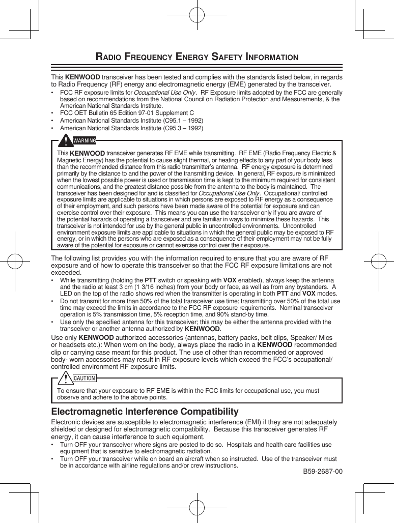
RF EXPOSURE STATEMENT FOR USERS MANUAL
USERS MANUAL
Navigation menu
Upload a User Manual
Namespaces
Wiki Guide
HTML
PDF
Info
Views
User Manual
Discussion / Help
Navigation