Kenwood KR 797 User Manual AUDIO VIDEO SURROUND RECEIVER Manuals And Guides 99010097
KENWOOD Receivers Manual 99010097 KENWOOD Receivers Owner's Manual, KENWOOD Receivers installation guides
User Manual: Kenwood KR-797 KR-797 KENWOOD AUDIO-VIDEO SURROUND RECEIVER - Manuals and Guides View the owners manual for your KENWOOD AUDIO-VIDEO SURROUND RECEIVER #KR797. Home:Electronics Parts:Kenwood Parts:Kenwood AUDIO-VIDEO SURROUND RECEIVER Manual
Open the PDF directly: View PDF ![]() .
.
Page Count: 32
KENWOOD
AUDIO VIDEO SURROUND RECEIVER
KR-897
KR-797
INSTRUCTION MANUAL
KENWOOD CORPORATION
This manual contains instructions for two models. Model availability and features 1(functions) may differ depending on country and sales area.
Model KR-897 is not available in except for U.S.A. and Canada. I
B60-3069-00 (_) (K, P, Y) i-.l_-C.'i
98/1211 1098765432 1 97"/12 11 109
KR-B97/KR-797 I1En)
IB..eforeauulvinonewer o.,o.: ensure safe operat#p .
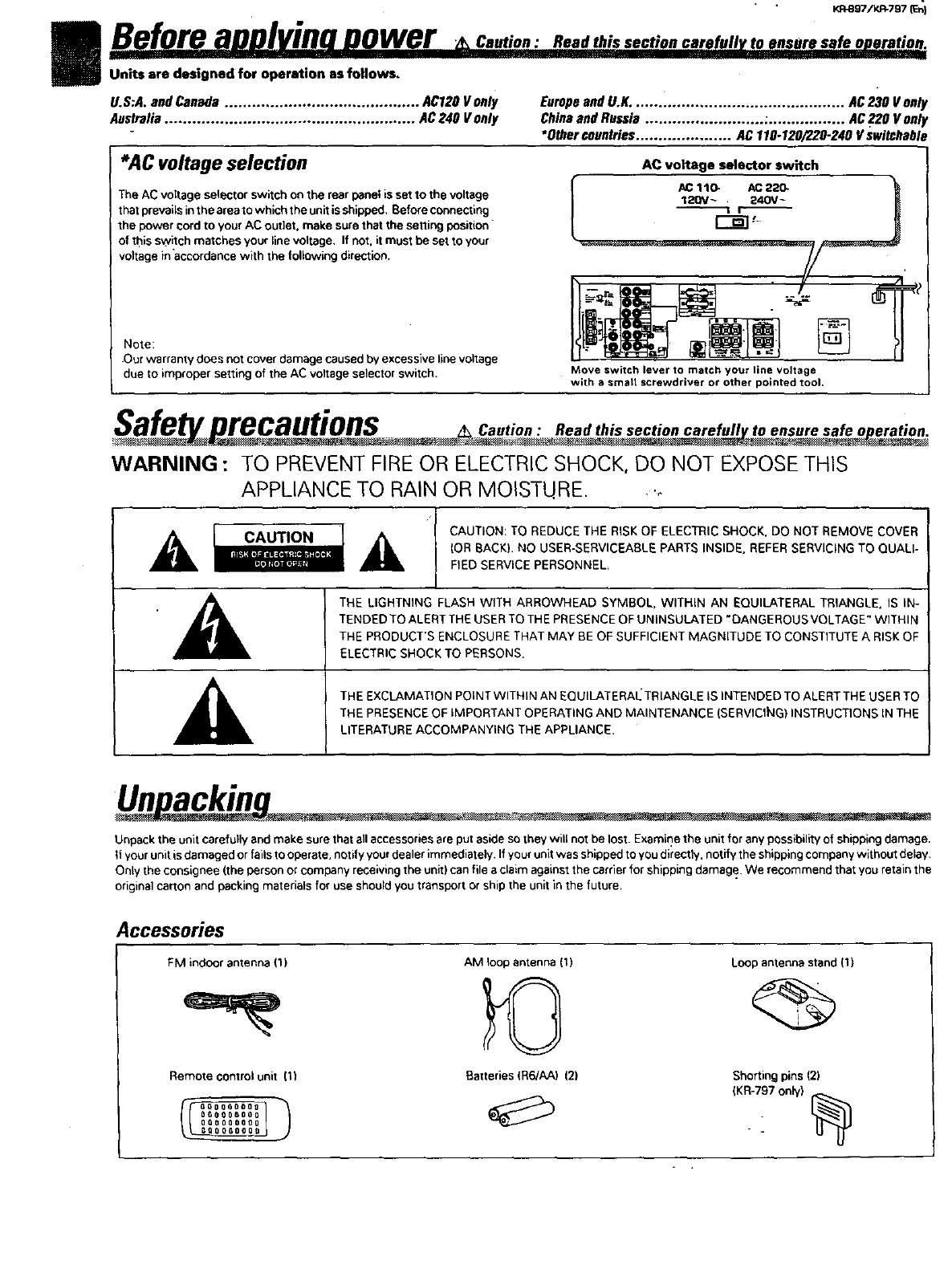
Units are designed for operation as follows,
U.S:A. and Canada ........................................... AC120 V only Europe and UoK. .............................................. AC 230 V only
Australia ....................................................... AC240 V only China and Russia .......................... :................. AC 220 V only
•Other countries ..................... AC 110-120/22.0-240 V switchable
*AC voltage selection AC voltage selector switch
The AC voltage selector switch oe the rear panel is set to the voltage
that prevailsin the areato which the unit is shipped, Beforeconnecting
the power cord to your AC outlet, make sure that the setting position
of this switch matches your linevoltage, If not. it mustbe set to your
voltage inaccordance with the renewing direction.
Note:
•Our warranty does not cover damage caused by excessive line voltage
due to improper setting of the AC voltage selector switch. Move switch lever to match your line voltage
with asmart screwdriver or other pointed tool,
recautions Oantioa Read this section carefull to ensure safe o eratioa
WARNING : TO PREVENT FIRE OR ELECTRICSHOCK, DO NOT EXPOSETHIS
APPLIANCE TO RAIN OR MOISTURE. ._
A c,uT,o. CAUTION: TO REDUCE THE RISK OF ELECTRIC SHOCK. DO NOT REMOVE COVER
(OR BACK)•NO USER-SERVICEABLE PARTS INSIDE. REFER SERVICING TO QUALI-
FIED SERVICE PERSONNEL,
p_*]_l[*ltl=,J1
IkTHE LIGHTNING FLASH WITH ARROWHEAD SYMBOL, WITHIN AN EQUILATERAL TRIANGLE. IS IN-
TENDED TO ALERT THE USERTO THE PRESENCE OF UNINSULATED ,DANGEROUS VOLTAGE" WITHIN
._ THE PRODUCT'S ENCLOSURE THAT MAY BE OF SUFFICIENT MAGNITUDE TO CONSTITUTE A RISK OF
ELECTRIC SHOCK TO PERSONS•
THE EXCLAMATION POINT WITHIN AN EQUILATERAI_ TRIANGLE IS INTENDED TO ALERT THE USER TO
Unacki - _. . -.-
Unpack the unit carefully and make sure that all accessoriesare put aside so .,heywill not be lost. Examine the unit for any possibilityof shipping damage.
if your unit is damaged or fails tooperate, notify your pealer immediately. If your unit was shipped to you directly, notify the shipping company without delay.
Only the consignee (the person or company receiving the unit) can file aclaim against the carrier for shipping damage. We recommend that you retain the
original carton and packing materials for use should you transport or ship the unit in the future.
Accessories
FM indoor antenna {1)
Remote control unit 11)
oo0000o0_
_O_Q__OGOOOgO00
OQOSQO088
AM loop antenna (1)
Batteries (R6/AA) 121
Loop antenna stand (1)
Shorting pins (2)
(KR-797 only)
--
Suecialfeatures.............,
DOLBYPROL,QG!C,&OOLBY3STEREO
..... rII
Y.R_97/KR-797 (En]
The surround system reproducus eideo software programs carrying the I'1r1[_ mark with similar acoustic effects to movie
theaters.
The DOIJ_Y PRO LOGIC mode controls the audio signals of the Front Left/Rigid, Center and Rear surround channels using the built-in
diroctivity enhancer cercuit to reproduce the feeling of sound motions very realistically.
TheDOLB Y3 STEREO mode can reproduce the motions ofsoundeven when oulythu frontand center speakers are used,byproviding proper
acoustic position using the diroctivity enhancer circuit,
SRS 3D Stereo .........
The SRS (Sound Retrieval System) is an innovative system simulating a 3-dimensioual sound space, which features clearly improved
feelings of depth, sound field extension and acoustic image positioning as well as e widened listening area.
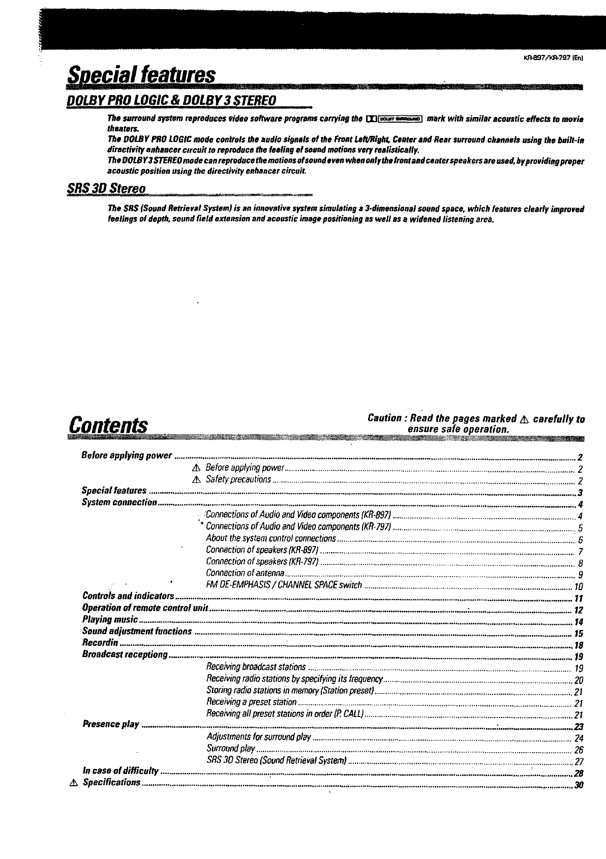
Contents Oautio. : Read the pages marked _carefully to
ensure safe operation.
_.- _ . -.
Before applying power .............................................................................................................................................................................................2
,_ Beforeapplyingpower .........................................................................................................................................2
z_ Safety precautions...............................................................................................................................................2
Special features .........................................................................................................................................................................................................3
System connection ....................................................................................................................................................................................................4
: :Connectionsof Audio andVideocomponents(KR-897) .................................................... 4
°Connectionsof Audio and Videocomponents(KR-797)......................................................................................5
About the systemcontrolconnections.................................................................................................................6
Connectionof speakers(KR-897)........................................................................................................................7
Connectionof speakers(KR-797)........................................................................................................................8
Connectionof antenna.........................................................................................................................................9
FM OE-EMPHASIS/ CHANNELSPACEswitch ........................................................... I0
Controlsand indicators .........................................................................................................................................................................................11
Operation of remote control unit ..........................................................................................................................:................................................12
Playing music ...........................................................................................................................................................................................................14
Sound adjustment functions ..................................................................................................................................................................................15
Recordin .............................................................................L......................................................................................................................................18
Broadcast receptiong ..............................................................................................................................................................................................19
Receivingbroadcaststations ....................................................................................._......................................19
Receivingradiostations byspecifyingits frequency.........................................................................................20
Storingradio stationsin memory(Stationpreset) ........................................... 21
Receivinga preset station...........................................:.....................................................................................21
Receivingall preset stationsin order(P.CALL)..................................................................................................21
Presence play .......................................................................................................................................................................:..................................23
Adjustmentsfor surroundplay ..........................................................................................................................24
Surroundplay .....................................................................................................................................................26
SRS30 Stereo(SoundRetrievalSystem)..........................................................................................................27
In case of difficulty ...................................................=..........................................................................................................................:...................28
z_ Specifications ...........................................................................................................................................................................................................30
KP.897/KR*797 IEn]
C nnectionsofAudio and Videocorn onents KR-B97
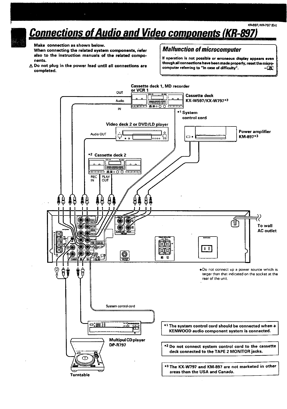
Make connection as shown below.
When connecting the related system components, refer
also to the instruction manuals of the related compo-
nents.
Do not plug in the power lead until all connections are
completed.
lMalfunction ofmicrocomputer !
if operation is not possible or erroneous display appears even
thoughall connections have been made properly, reset the micro- |
computer referring to "In case of difficulty'. -_ [
Cassette deck 1, MD recorder
or VCR 1
__1_ Cassette deck
I__l KX'WS971KX'W797"3
=-=o o o c_:_ I
.I System
control cord
Video deck 2 or DVD/LD player
*2 Cassettedeck2
Power amplifier
KM.897-3
OO
To wall
AC outlet
•System control cord
M;! tR7P;71CDplayer
Turntable
•Do not connect up a power source which is
larger than that indicated on the socket at the
rear of the unit.
I" }
The system control cord should be connected when a
KI=NWOOD audio component system is connected.
e2 Do not connect system control cord to the cassette 1
deck connected to the TAPE 2 MONITOR jacks. /
*3 The KX-W797 and KM-897 are not marketed in other
areas than the USA and Canada.
_7/K_797 JEt
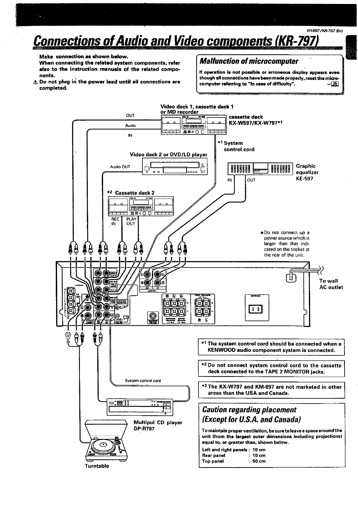
ConnectionsofAudioandVideocomuonents(KR-797)
Make connection as shown below.
When connecting the related system components, refer
also to the instruction manuals of the related compo-
nents.
/k Do not plug in the power lead until all connections are
completed.
IMalfunction of microcomputer .
If operation is not possible or erroneous display appears even
though all connections have been made properly, reset the micro-
computer referring to "In case of difficulty'. -[_.
!
OUT
Audio
IN
Video deck 1, cassette deck 1
or MD recorder
KX-W597/KX-W797 .1
Video deck 2 or DVD/LD I_layer
-1 System
control cord
*2 Cassette deck 2
•Do not connect up a
power source which is
larger than that indi-
cated on the socket at
the rear of the unit.
%
System control cord
Turntable
Multipul CD player
DP-R797
-1 The system control cord should be connected when a
KENWOOD aud o component system is connected.
*2 Do not connect system control cord to the cassette I
Ideck connected to the TAPE 2 MONITOR jacks, t
*3 The KX-W797 and KM-897 are not marketed in other I
areas than the USA and Canada. I
Caution regarding placement
(Except for U.S.A. and Canada)
To maintain proper ventilation, be su re to leave a space around the
unit (from the largest outer dimensions including projections)
equal to, or greater than, shown below.
Left and right panels : 10 cm
Rear panel : 1Ocm
Top panel : 50 cm
I
I
K/3897/KR-797 ten)
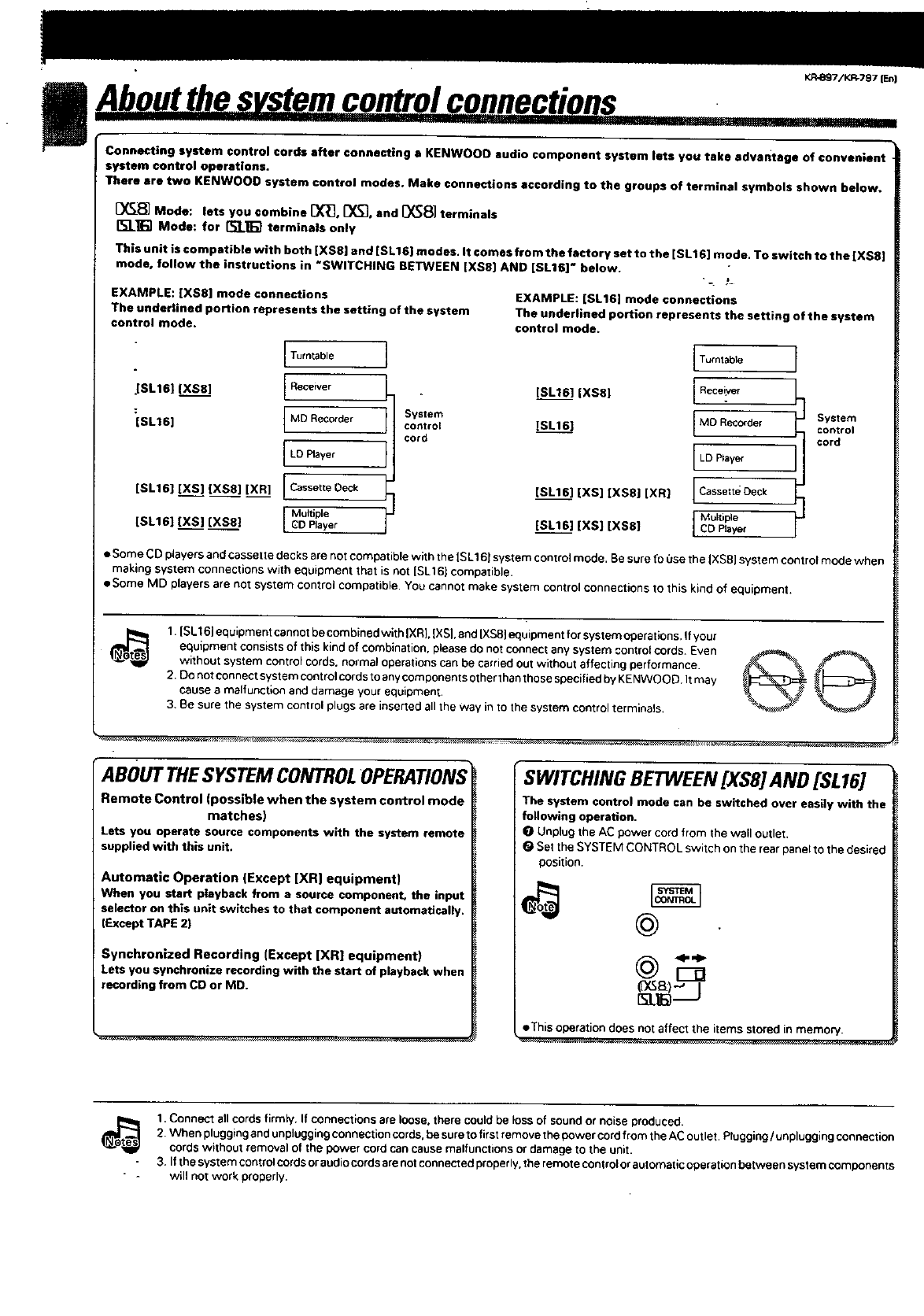
Connecting system control cords after connecting a KENWOOO audio component system lets you take advantage of convenient
system control operations.
There ere two KENWOOO system €ontrol modes. Make connections according to the groups of terminal symbols shown below.
[_ Mode: lets you combine [X_, _f_], and [_8] terminals
I%'J_] Mode: for [t;l_] terminals only
This unit is compntible with both iXSS] and [SLIE) modes. It comes from the factory set to the [SL16] mode. To switch to the [XS8]
mode, follow the instructions in *SWITCHING BETWEEN [XS8] AND [SL16]" below.
)
EXAMPLE: iXS8] mode connections
The uncle€tined portion rep;esents the setting of the system
control mode.
Turntable
JSL161 (XS8] [Receiver
:[SLt 6] IMDRec°rder ISystemcontrol
cord
ILD PlaYer I
teL16] [XS] [XS8] [XR] [ Cassette Deck
[SL16] [XS] [XS8} I MultipleGD Player I
EXAMPLE: [eL16] mode connections
The under|ined portion represents the setting of the system
control mode.
ITumtable
1
[SL16] [XS8] IReceiver
IMD Recorder System
[SL161 Icontrol
cord
I LDPlayer
teLl6] [XS] [XS8] [XR] LcassetteDeck
IMuaiple
[SL161 [XS] [XS8] ICDBayer
•Some CD players and cassette decks are not compatible with the [SL161 system control mode. Be sure fo 0se the IXS8] system control mode when
making system connections with equipment that is not ISLtC) compatible,
•Some MD players are not system control compatible• You cannot make system control connections to this kind of equipment.
1. |eLI 6_equipment cannotbe combined with |XRL |XS|. and IXSS_equipment for system operaryans. _fyou[
equipment consistsof this kind of combination, please do not connect any system control cords. Even
without system control cords, normal operations can be earnedout without affecting performance.
2. Do not connect system controlcords to any componentsother than those specified by KENWOOD It may
cause a malfunction and damage your equipment.
3. Be sure the system control plugs are inserted all the way in to the system control terminals,
ABOUT THESYSTEM CONTROLOPERATIONS
Remote Control (possible when the system control mode
matches)
Lets you operate source components with the system remote
supplied with this unit.
Automatic Operation (Except [XR] equipment)
When you start p|ayback from a source component, the input
selector on this unit switches to that component automatically.
(Except TAPE 2)
Synchronized Recording (Except [XR| equipment)
Lets you synchronize recording with the start of playback when
recording from CD or MD.
SWITCHING BETWEEN [XS8] AND [SL16]
The system control mode can be switched over easily with the
following operation,
I_ Unplug the AC power cord from the wall outlet,
(_ Set the SYSTEM CONTROL switch on the rear panel to the desired
position.
(DG_)-' I
• This operation does not affect the items stored in memory.
i_ 1. Connect all cords firmly, If connections are loose, there could be loss of sound or noise produced.
2. When plugging and unplugging connection cords, be sure to first remove the power cord from the AC outlet• Plugging/unplugging connection
cordswithout removal of the 9owe_ cord cancause matfunctv3ns o_damage to the unit.
3. If the system control cordsor audiocordsarenot connected properly, the remote controlor automatic operation between system components
will not work properly.
KR-Sg7/KR=797 (En}
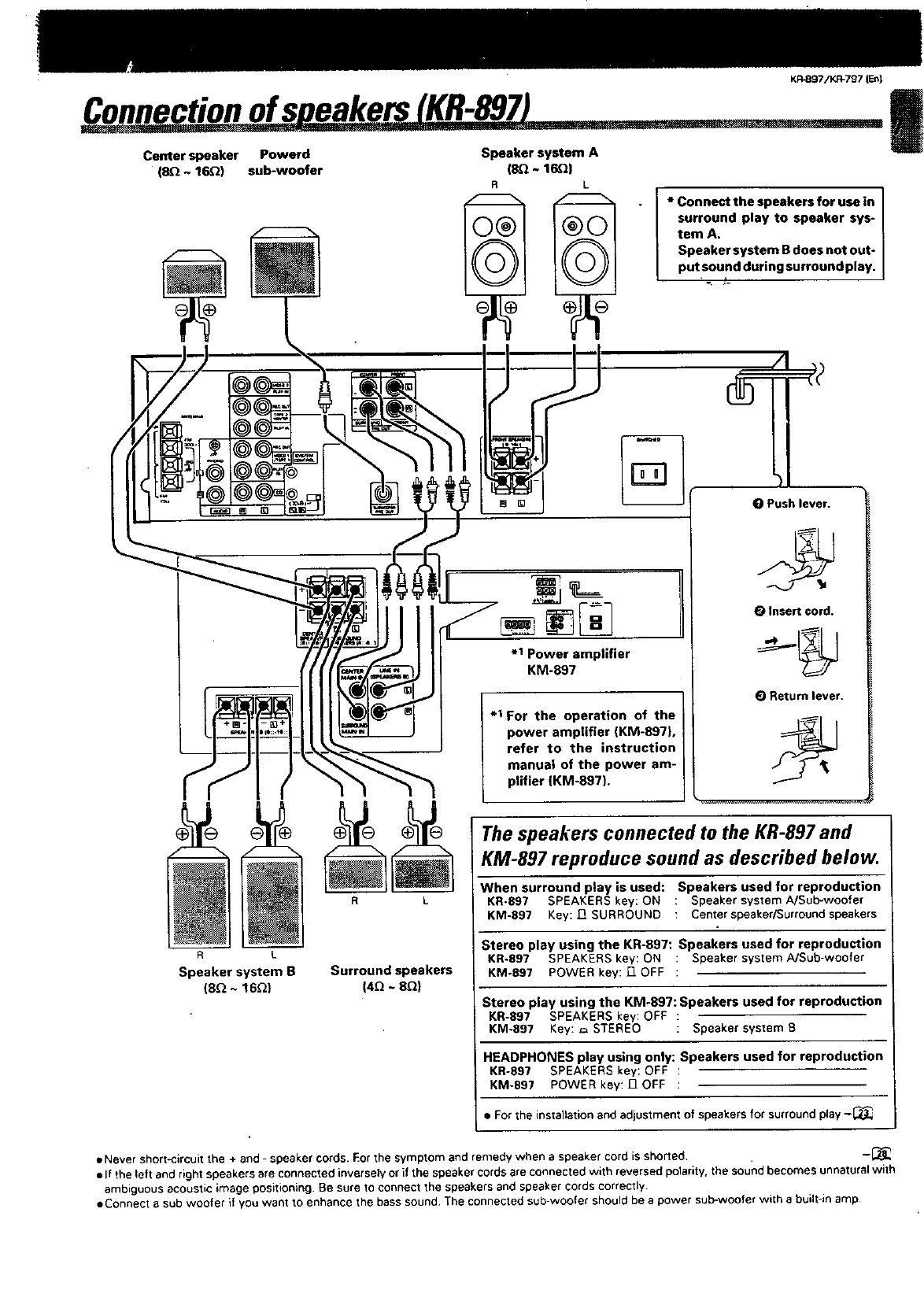
Connectionofs eakers KR-897 I
Center speaker Powerd
(SQ ~ 16_) sub-woofer
Speaker system A
(8.Q~ 16Q)
• I *Connectthespeakersforusein
surround play to speaker sys-
tem A.
Speaker system B does not out-
putsound during surround play.
i
°. _.
Speaker system B
(8_ ~16_)
R L
Surround speakers
(4_ ~ 8Q)
%
.1 Power amplifier
KM-897
.1 For the operation of the
power amplifier (KM-897),
refer to the instruction
manual of the power am-
plifier (KM-897).
OPush lever.
OInsert cord.
(_ Return lever.
The speakers connected to the KR-897 and
KM-897 reproduce sound as described below.
When surround play is used: Speakers used for reproduction
KR-897 SPEAKERS key: ON :Speaker system A/Sub-woofer
KM-897 Key: J_ SURROUND :Center speaker/Surround speakers
Stereo play using the KR-897: Speakers used for reproduction
KR-897 SPEAKERS key: ON : Speaker system A/Sub-woofer
KM-897 POWER key: ["1OFF ;
Stereo play using the KM-897: Speakers used for reproduction
KR-897 SPEAKERS key: OFF :
KM-897 Key: _ STEREO :Speaker system B
HEADPHONES play using only: Speakers used for reproduction
KR-897 SPEAKERS key: OFF :
KM-897 POWER key: 17 OFF :
• For the installation and adjustment of speakers for surround play -_
•Never short-circuit the + and - speaker cords. Eor the symptom and remedy when a speaker cord is shorted. -_
•If the left and right speakers are connected inversely or if the speaker cords are connected with reversed pelarity, the soundbecomes unnatural with
ambiguous acoustic image positioning. Be sure to connect the speakers and speaker cords correctly.
eConnect a sub woofer if you want to enhance the bass sound The connected sub-woofer should be apower sub-woofer with abuilt-in amp
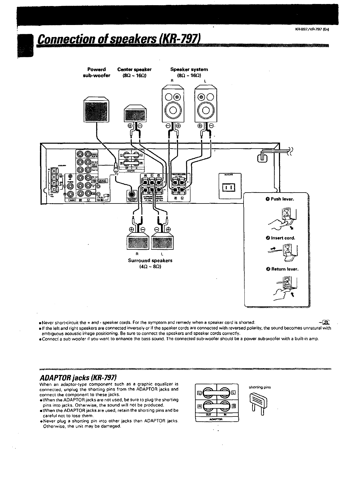
€onnection of spqakersr_ ,
Powerd Center speaker Speaker system
sub-woofer (8Q ~16_) (SQ - 16Q)
KR_97/KP,-797 {En)
RL
Surround speakers
(4_ ~ 8_)
0Push lever.
0Insert cord.
0Return lever.
• Never short-circuit the + end -speaker cords. For the symptom and remedy when aspeaker cord is shorted: -_
elf the left and right speakers are connected inversely or if the speaker cords are connected with reversed polarity, the sound becomes unnatural with
ambiguous acoustic image positioning. Be sure to connect the speakers and speaker cords correctly.
eConnec_ a sub woofer if you want to enhance the bass sound. The connected sub-woofer should be apower sub-_Nooferwith a built-in amp.
ADAPTORjacks (KR-797)
When an adaptor-type component such as agraph;c equalizer is J1
connect the component to these jacks. [] []
eWhen the ADAPTOR jacks are not used, be sure to plug the shorting
pins into jacks. Otherwise. the sound will not be produced. [] []
eWhen the ADAPTOR jacks are used. retain the shorting pins and be
careful not to lose them.
eNever plug ashorting pin into other jacks than ADAPTOR jacks.
Otherwise. the unit may be damaged,
KR.897iKR-797 {L_)
Connectionof_antenna I
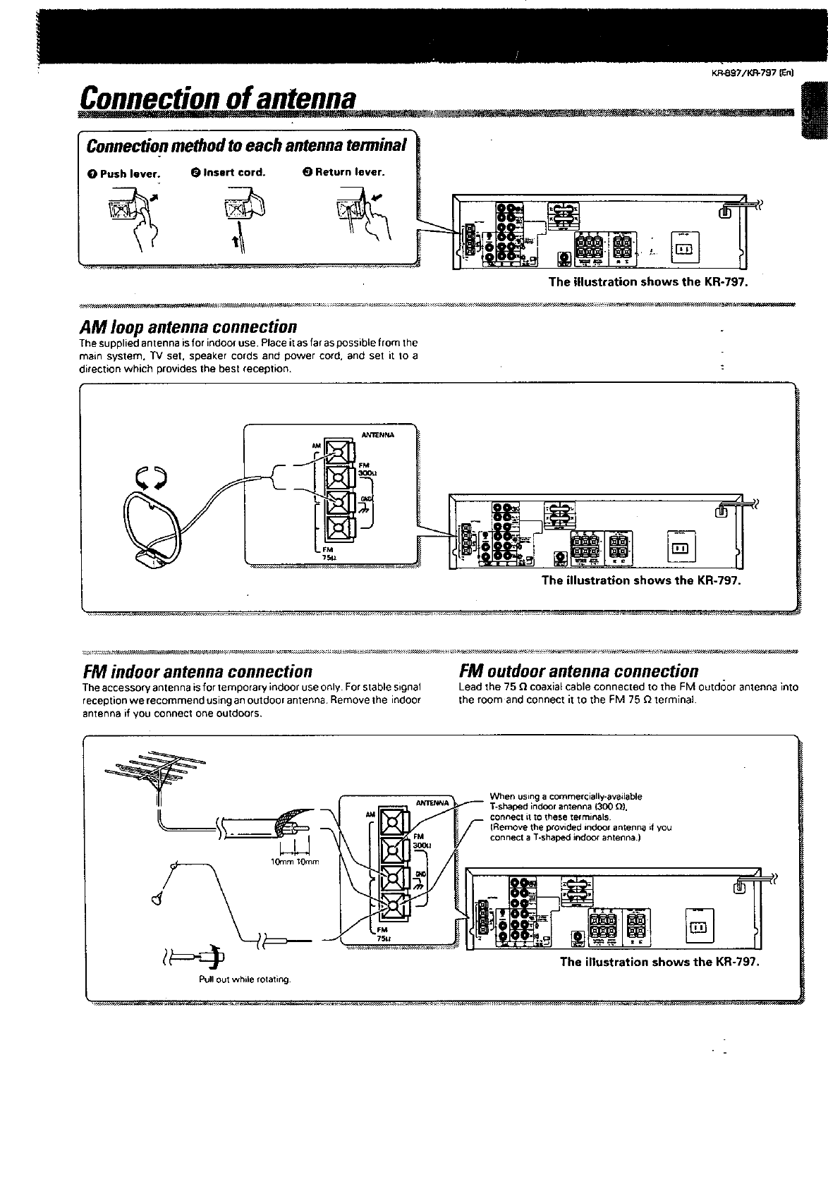
Connectionmethodtoeach antennaterminal
OPush lever. OInsert cord. (_ Return lever.
The illustration shows the KR-797.
AM loop antenna connection
The supplied antenna is for indoor use. Place it as far as possible from the
main system. TV set, speaker cords and power cord. and set _t 1o a
direction which provides the best reception.
The illustration shows the KR-797.
FM indoor antenna connection
The accessory antenna isfor temporary indoor use only. For stable signal
reception we recommend using an outdoor antenna Remove the indoor
antenna if you connect one outdoors.
FM outdoor antenna connection
Lead the 75 _coaxial cable connected to the FM outdoor antenna into
the room and connect it to the FM 75 _ terminal•
When using a commercially-available
1300 _).
connect itto these terminals
(Remove the provided indoor antenr_ if you
connect aT-shaped indoor antenna.)
1GramIOmm
Pug OUtwhi_e rota_ing_
The illustration shows the KR-797.
|
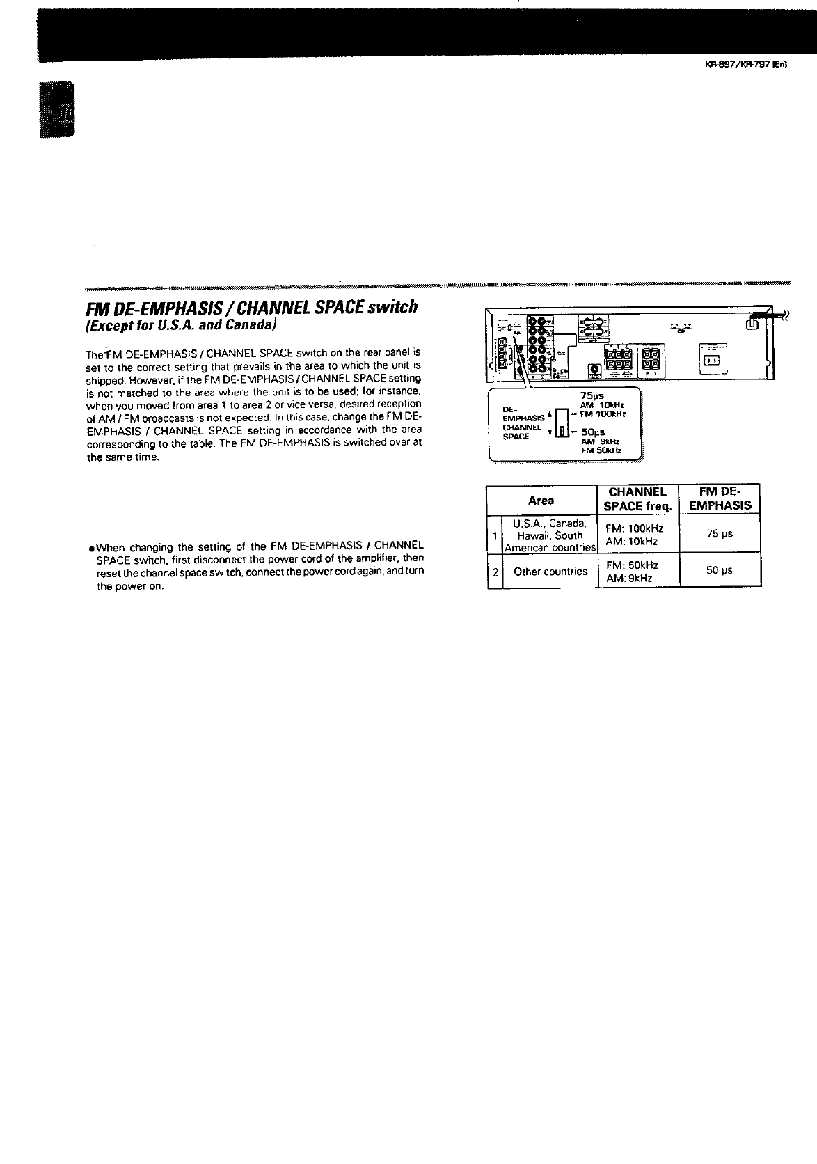
FM DE-EMPHASIS/CHANNEL SPACEswitch
(Except for U.S.A. and Canada)
The:FM DE-EMPHASIS /CHANNEL SPACE switch on the rear panel is
set to the correct setting that prevails in the area to which the unit is
shipped. However. ifthe FM DE-EMPHASIS /CHANNEL SPACE setting
is not matched to the area where the unit is to be used; for instance.
when you moved from area Ito area 2 or vice versa, desired reception
of AM /FM broadcasts is not expected. In this case. change the FM DE-
EMPHASIS /CHANNEL SPACE setting in accordance with the area
corresponding to the table The FM DE-EMPHASIS is switched over at
the same time.
OE- AM 1C4_HZ
EMPHAE;IS & -- FM lOOkHz
I - 50_sCHANNEL
SPI SPACE _M gkHz l
FM SOl_tz
%
eWhen changing the setting of the FM DE-EMPHASIS /CHANNEL
SPACE switch, first disconnect the power cord of the amplifier, then
reset the channel space switch, connect the power cordagain, and turn
the power on.
CHANNEL FM DE-
Area SPACE freq. EMPHASIS
U.SA, Canada, FM: 1OOkHz 75 ps
1 Hawaii. South AM: 1OkHz
American countries
2Other countries FM: 50kHz 50 ps
AM: 9kHz
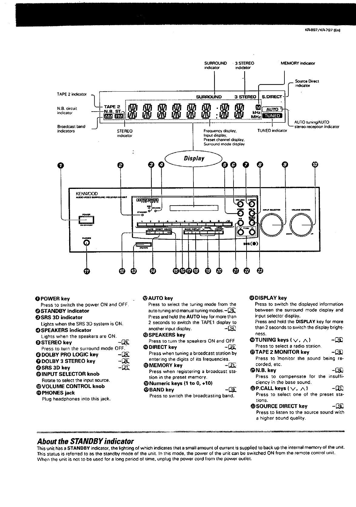
TAPE 2 indicator
N.B. circuit
indicator
Broadcast band
indicators
KR4997/V.R_797 [_]
OPOWER key
Press to switch the power ON and OFF.
OSTANDBY indicator
OSRS 3D indicator
Lightswhen the SRS 3D system is ON.
OSPEAKERS indicator
Lights when the speakers are ON.
OSTEREO key -_
Press to turn the surround mode OFF,
ODOLBY PRO LOGIC key -_
ODOLBY 3 STEREO key -_
QSRS 3D key -_
OINPUT SELECTOR knob
Rotate to select the input source.
@VOLUME CONTROL knob
@PHONES jack
Plug headphones into this jack,
@AUTO key
Press to select the tuning mode from the
auto tuningand manual tuning modes.-_
Press and hold the AUTO key for more than
2seconds to switch the TAPE1 display to
another input display. -_
_SPEAKERS key
Press to turn the speakers ON and OFF
DIRECT key -_
Press when tuning a broadcast station by
entering the digits of its frequencies.
MEMORY key -_
Press when registering a broadcast sta-
tion in the preset memory•
O Nurneric keys (1 to 0, +10)
@BAND key -_
Press to switch the broadcasting band.
@DISPLAY key
Press to switch the displayed information
between the surround mode display and
input selector display.
Press and hold the DISPLAy key for more
than 2seconds to switch the displaybrigh t-
ness,
@TUNING keys ( V, A) -_
Press to select a radio station•
@TAPE 2 MONITOR key -_
Press to "monitor the sound being re-
corded, etc,
_N.B. key -_
Press to compensate for the insuffi-
ciency in the base sound.
OP.CALL keys ( v, A ) -I_,
Press to select one of the preset sta-
tions.
@SOURCE DIRECT key -13_
Press to listen to the source sound with
ahigher sound quality.
About the STANDBY indicator
This unit has a STANDBY indicator, the lighting of which indicatesthat a smallamount of current is supplied to back up the internal memory of the unit.
This status is referred to as the standby mode of the unit. In this mode. the power of the unit can be switched ON from the remote control unit.
When the unit is not to be used for a long period of time. unplug the power cord from the power outlet.
KF_sg7/KI_797 (En]
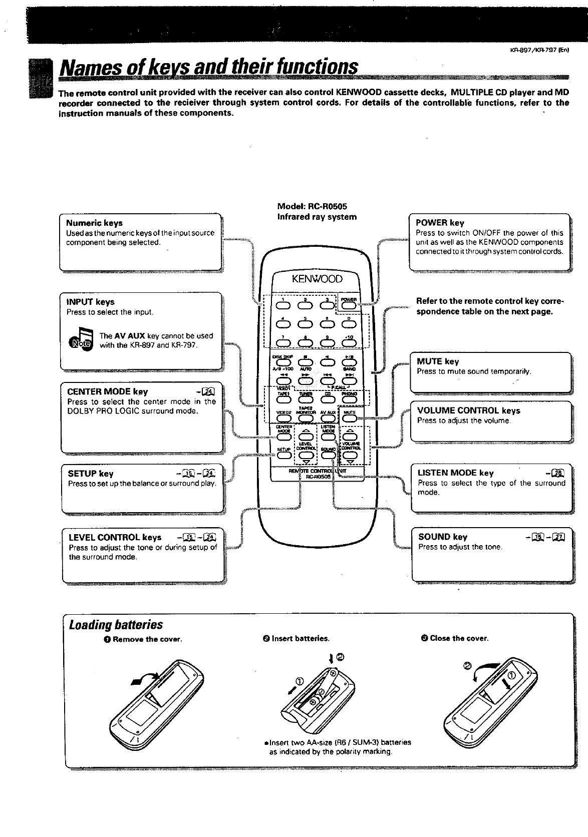
INamesofke s andtheirfunctions
The remote control unit provided with the receiver can also control KENWOOD cassette decks, MULTIPLE CD player and MD
recorder connected to the recieiver through system control cords. For details of the controllable functions, refer to the
instruction manuals of these components.
Numeric keys
Used as the numeric keys of the input source
component being selected.
INPUT keys
Press to select the input.
Model: RC-R0505
Infrared ray system POWER key
Press to switch ON/OFF the power of this
unit as well as the KENWOOD components
connected to it through system control cords.
The AM AUX key cannot be used
with the KR-897 and KR-797.
CENTER MODE key -_
Press to select the center mode in the
DOLBY PRO LOGIC surround mode.
Press to set up the balance or surround play,
KENWOOD
66
6666
Refer to the remote control key corre-
...... spondence table on the next page.
Press to mute sound temporarily.
keys
Press to adjust the volume
LISTEN MODE key -_
Press to select the type of the surround
mode.
Press to adjust the tone or during setup
the surround mode.
SOUND key -_-{_
Pressto adjustthetone
Loading batteries
0 Remove the cover. OInsert batteries.
t®
Jlnsert two AA-size (R6 /SUM-3) batteries
as indicated by the polarity marking.
(_ Close the cover.
d
KR-B97iKR-797 (En)
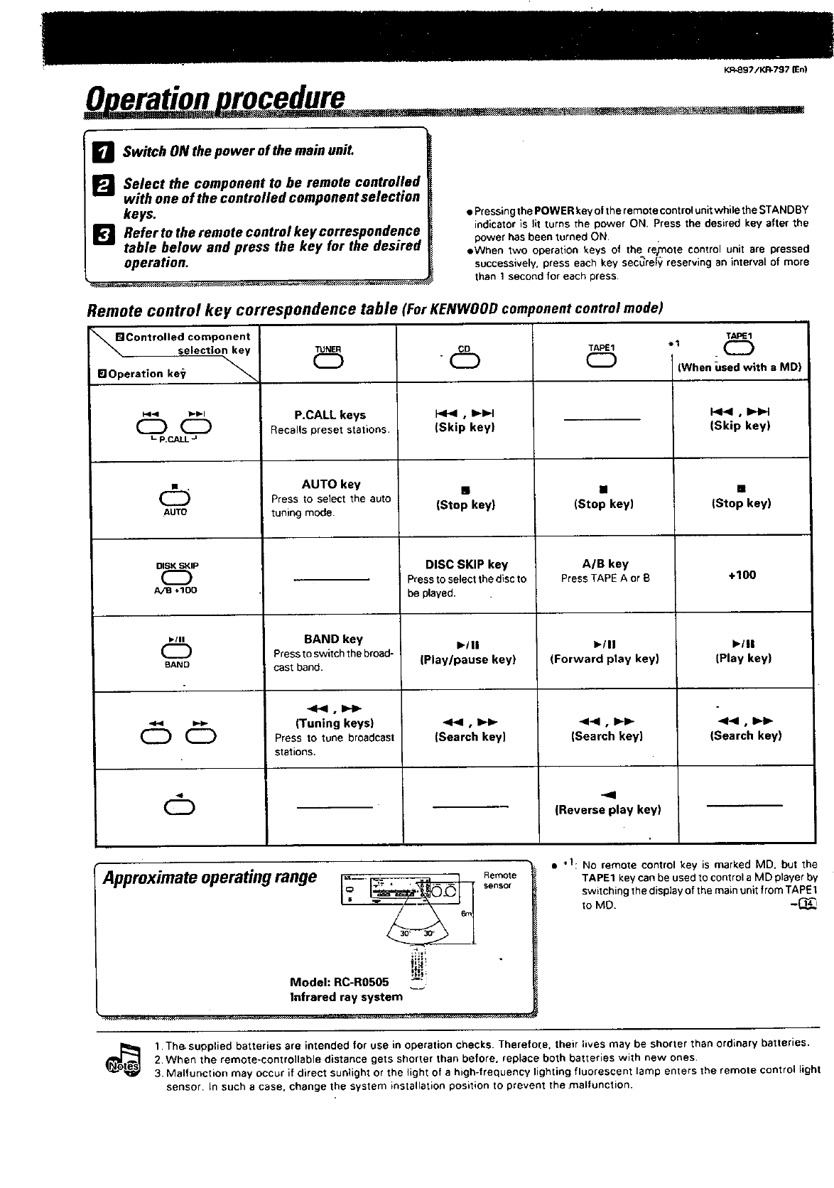
0 eration rocedure
r_ Switch ON the power ofthe main uni£
_Select the component to be remote controlled
with one of the controlled component selection
keys.
DRefertotheremotecontrolkeycorrespondence
table below and press the key for the desired
operation.
• Pressingthe POWER key of the remote control unit while the STANDBY
indicator is fit turns the power ON. Press the desired key after the
power has been turned ON.
• When two operation keys of the re_ote control unit are pressed
successively, press each key sec_ref_ reserving an interval of more
than 1second for each press
Remote control key correspondence table
Controlled component
selection key TUNER
SlOperation ke_
pe.< lpl_l
L P.CALL -_
P.CALL keys
Recalls preset stations.
'ForKENWOOD corn
CD
CD
(Skip key)
tonent control mode)
TAPE1
TAPE1 el (_
OI (When used with a MD)
(Skip key)
(_ AUTO key m [] []
Press to select the auto
AUTO tuning mode. (Stop key) (Stop key) (Stop key)
BAND key
Press to switch the broad-
cast band.
(Tuning keys)
Press to tune broadcast
stations.
DISK SKIP
CZ)
A/B .100
DISC SKIP key
Press to select the discto
be played,
I_III
(Play/pause key!
.<l<l,ll_l_
(Search key)
A/B key
Press TAPE A orb
I_/11
(Forward play key)
(Search key)
-el
(Reverse play key)
1-111
CD
BAND
CDCD
CD
+100
1-111
(Play key)
4Pel , 10H_
(Search key)
Approximate operating range l_-_, Re•too°ire
Model: RC-R0505 --'
Infrared ray system
• .1: NO remote control key is marked MD. but the
TAPE1 key can be used to control a MD player by
switching the display of the main unit from TAPE1
to Me. -_
_s 1. The-supplied batteries are intended for use in operation checks. Therefore. their lives may be shorter than ordinary batteries.
2. When the remote-controllable distance gets shorter than before, replace both batteries with new ones,
3. Malfunction may occur if direct sunlight or the light of a high-frequency lighting fluorescent lamp enters the remote control light
sensor In such acase. change the system installation position to prevent the malfunction.
|
6db_
.m
KR,897/KR-797 [En}
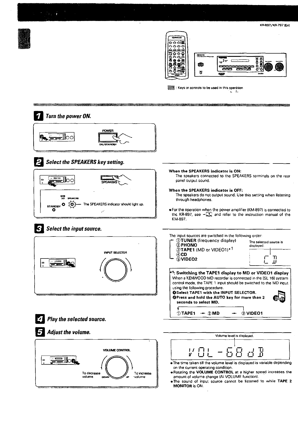
_: Keys or ¢ont fols to be used in this operation
aTurn the power ON.
POWER •
O
ol
Select the SPEAKERS key setting.
O_O_--'-- TheSPEAKERSindicatorshould
light up.
STANDBY
O
_l Select the input source.
tNPUT SELECTOR
_l Play the selected source.
_'_ Adjust the volume.
VOLUME CONTROL
Tv_°ldmeC_ease .vT_l_rmC_ease
When the SPEAKERS indicator is ON:
The speakers connected to the SPEAKERS terminals on the rear
panel output sound•
When the SPEAKERS indicator is OFF:
The speakers do not output sound. Use this setting when listening
through headphones.
• For the operation when tlle power amplifier (KM-897) is connected to
th_ KR-897, see -_ and refer to the instruction manual of the
KM-897.
The input sources are switched in the following order:
I,F_TUNER (frequency display) Theselectedsourceis
,@_PHONO displayed,
,_TAPE1 (MD or VIDE01)* 1
®CO 1
_VIDE02 ', I-- TI
L .U
,1: Switching the TAPE1 display to MD or VIDEO1 display
When aKENWOOD MD recorder is connected in the [SL 161system
control mode, the TAPE 1 input should be switched to the MD input
using the following _rocedure.
OSelect TAPE1 with the INPUT SELECTOR. [_
_Press and hold the AUTO key for more than 2
seconds to select MD.
f 1
_TAPE1 _ _MD "-_ _VIDE01
Volume level is displayed_
UL U_')_
eThe time taken till the volume level is displayed is variable depending
on the current operating condition,
eRotatln9 the VOLUME CONTROL at a higher speed increases the
amount of volume change (AI VOLUME function),
eThe sound of input source cannot be listened to while TAPE 2
MONITOR is ON
r=l
_7/K_797 [En]
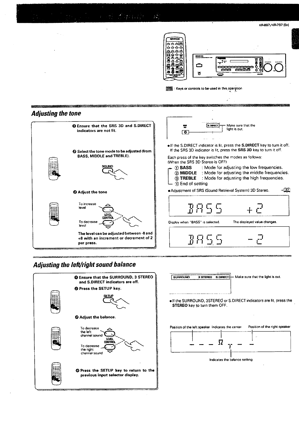
:Keys o¢ conb'ols to be used in this operation
I
Adjusting the tone
OEnsure that the SRS 3D and S.DIRECT
indicators are not lit.
Select the tone mode to be adjusted If tom
BASS, MIDDLE and TREBLE).
(_ Adjust the tone
To increase
lever
OONIgOL /" _To decre3se1_.,,_ s_
level
The level can be adjusted between -8 and
+8 with an increment or decrement of 2
per press.
=-- :s.ow_cT_,;_--Make sure that the
"" "_ light is out
elf the S.DIRECT indicator is lit. press the S.DIRECT key to turn it off.
If the SRS 3[:) indicator is lit. press the SRS 3D key to turn it off.
Each press of the key switches the modes as follows:
(When the SRS 3D Stereo is OFF)
BASS : Mode for adjusting the low frequencies.
_ (_:)MIDDLE :Mode for adjusting the middle frequencies.
(_TREBLE :Mode for adjusting the high frequencies.
'_ End of setting
• Adjustment of SRS (Sound Retrieval System) 3D Stereo. -I_
T, c ,- ,:,
.0 _::_ +_
Display when "BASS" is selected. The displayed value changes.
,q'5': -'
.!-- I'"
Adjusting the left/right sound balance
OEnsure that the SURROUND, 3 STEREO
and S.DIRECT indicators are off.
Press the SETUP key.
SETUP
(_ Adjust the balance.
To decrease
the left
channeJsound'd_
LctJEL _
To d_crease _
the right
channeisound
OPress the SETUP key to return to the
previous inputs elector display.
Makesuehthe.ou
•If the SURROUND, 3STERE0 or S.DIRECT indicators are lit, press the
STEREO key f;o turn them OFF.
Positionof the left speaker Indicates the center Position of the right speaker
!
Indicates the balance setting
KR..Sg7/IO_797 (En)
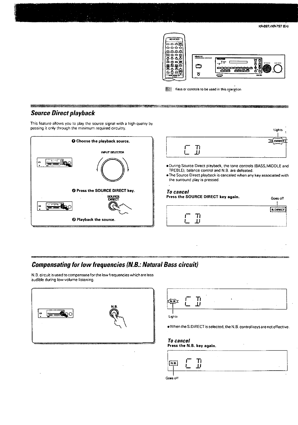
_Keys or controls to be used in this oberption
Source Direct playback
This feature allows you to play the source signal with a high qualiWby
passing it only through the minimum required circuitry.
O Choose the playback source.
IN_=UT_'IJECTOR
0Press the SOURCE DIRECT key.
SOURCE
_RECT
I.=
Playback the source.
J-- "I-I
L_ /I
Lkjhts
J
•During Source Direct playback, the tone controls (BASS,MIDDLE and
TREBLE), balance control and N.B. are defeated.
eThe Source Direct playback is canceled when any key associated with
the surround play is pressed.
To cancel
Press the SOURCE DIRECT key again. Goesoff
t...Jo...._l
, S.DIRECT:
I-- 7"1 ...........I j.!
Compensatingfor low frequencies (N•B.:Natural Bass circuit)
N.B. circuitis used tocompensate for the low frequencies which are less
audible during low-volume listening,
a.e,
I.
[
I_ jj
Lights
•When Ihe S.DIRECT is selected, the N.B. control keys are not effective•
To cancel
Press the N.B. key again.
i
r-H-_
_] L JJ
Goes off
c_
o
KR-897iKI:I-?97 (En]
J "-@-" °_ ....
o_oI
:Keys or controls to be used in this ol:eration
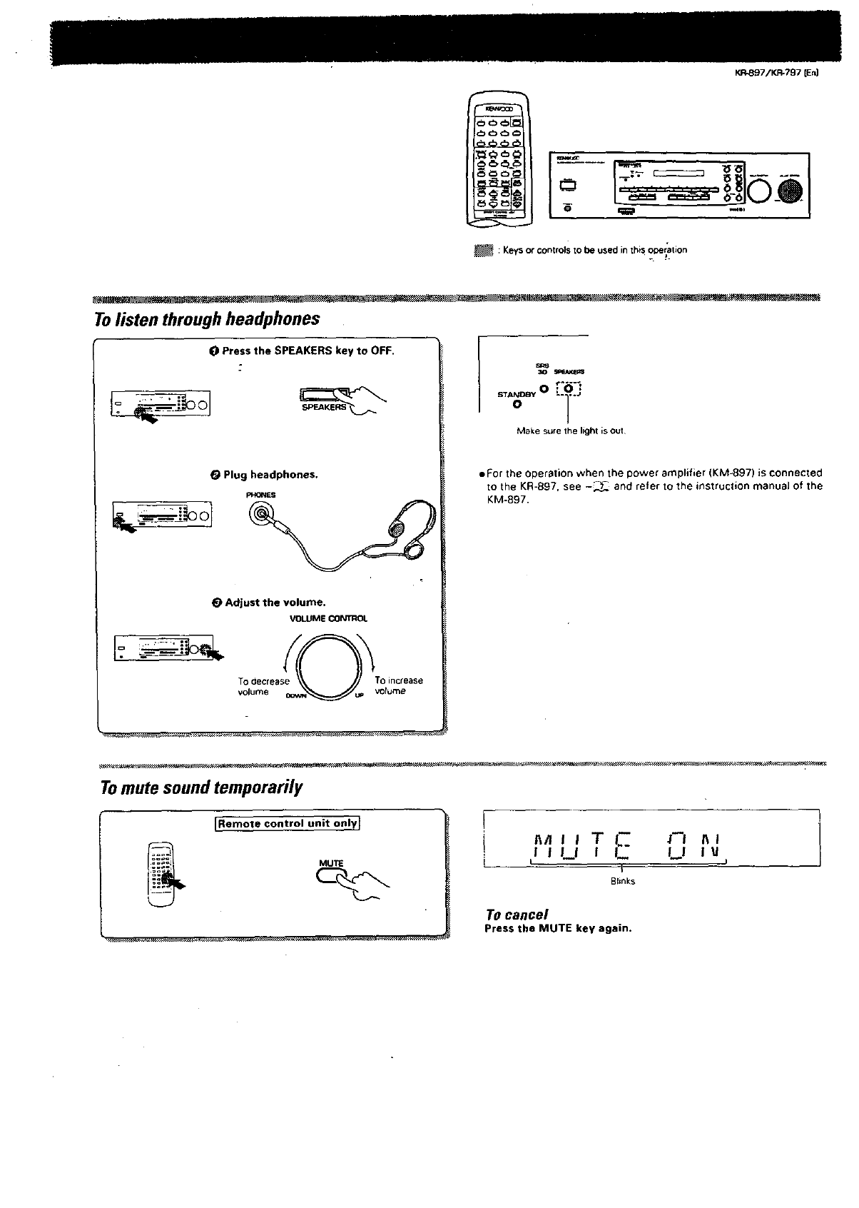
Tolisten through headphones
0 Press the SPEAKERS key to OFF.
OPlug headphones.
_-_0
_) Adjust the volume,
VOLUME CONTROl.
ST_C_Yo0 :.i.j
Make sure the light is out
• For the operation when the power amplifier (KM-897) is connected
to the KR-897, see -_ and refer to the instruction manual of the
KM-897.
Tomute sound temporarily
JRemote control unit only I
MUTE
n_J I T I.'- ._ nl
JJUIJ_ U iu
I I
t
Blinks
To cancel
Press the MUTE key again.
KR-BS7/K_7S7 IEn|
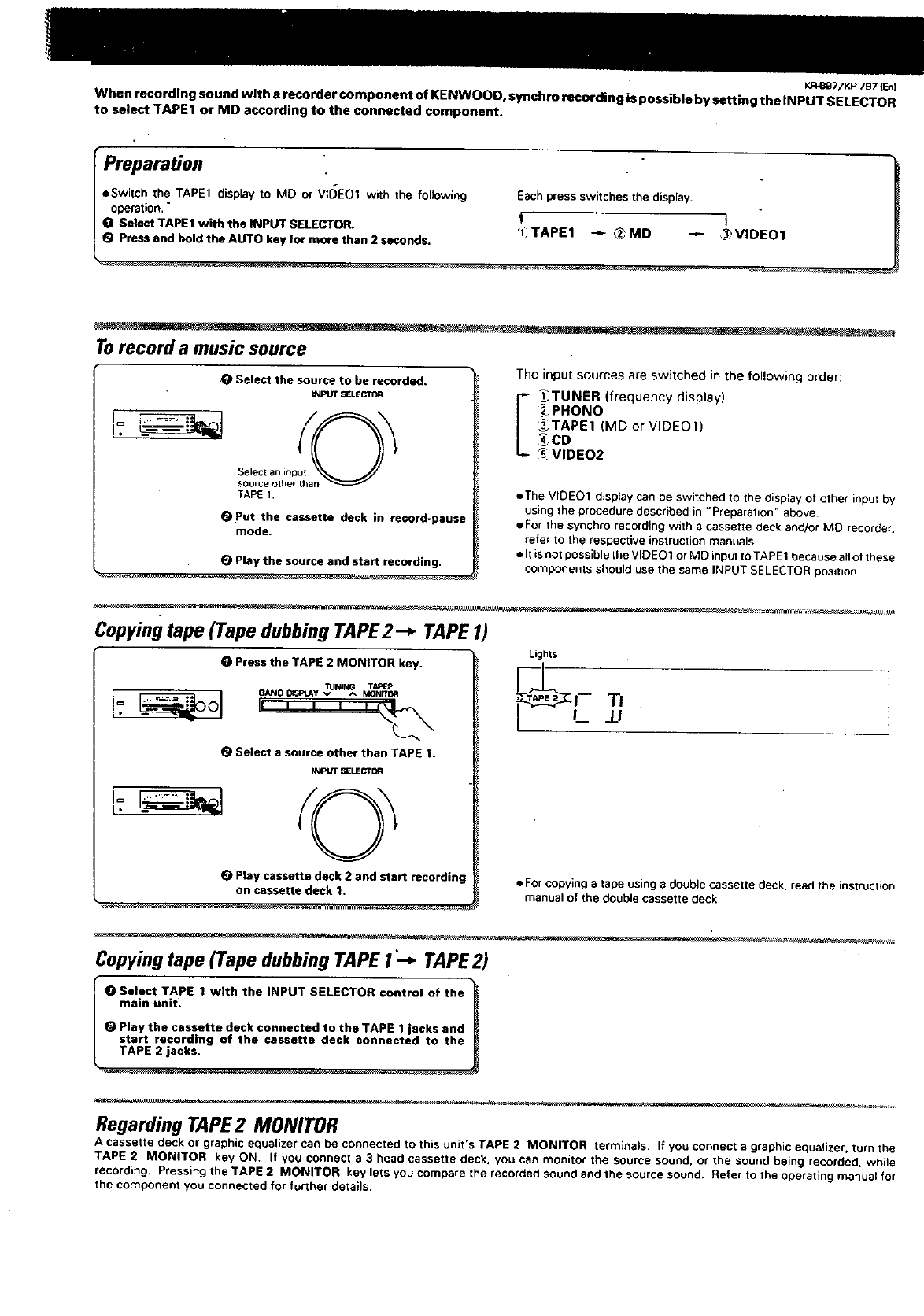
When recording sound with a recorder component of KENWOOD, synchro recording is possible by setting the INPUT SELECTOR
to select TAPE1 or MD according to the connected component.
IPreparation
eSwitch the TAPE1 display to MO or VIDE01 with the following Each press switches the display.
operation."
O Select TAPE1 with the INPUT SELECTOR. I
T
(_ PressandholdtheAUTOkeyformorethan2seconds. _LTAPE1 -_ _MD -'- ,._VIDEO1
Torecord a music source
Select the source to be recorded.
It4PMT,_ELIECT]DR
TAPE1.
(_ Put the cassette deck in record-pause
mode.
e Play the source and start recording.
The input sources are switched in the following order:
I _TUNER (frequency display)
PHONO
_TAPE1 (MD or VIDE01)
cD
VIDEO2
•The VIDEO1 display can be switched to the display of other input by
using the procedure described in "Preparation" above.
• For the synchro recording with a cassette deck and/or MD recorder.
refer to the respective instruction manuals..
• It is not possible the VIDE01 or MD input to TAPE1 because allof these
components should use the same INPUT SELECTOR position.
Copying tape (Tape dubbing TAPE2-* TAPE 1)
OPress the TAPE 2 MONITOR key.
_o _v _MN_ T_2
OII Ii_ i
Select a source other than TAPE 1.
R_atJT SELECTOR
0Play cassette deck 2 and start recording
on cassette deck t.
Lights
.tJ
•Forcopying atape using a double cassette deck. read the instruction
manual of the double cassette deck.
Copying tape (Tape dubbing TAPE 1:+ TAPE2)
!_ Select TAPE 1 with the INPUT SELECTOR control of the
"P::iY:_:i_assette deck €onnected to the TAPE 1 jacks and
Regarding TAPE2 MOMTOR
A cassette deck or graphic equalizer can be connected to this unit's TAPE 2 MONITOR terminals. If you connect a graphic equalizer, turn the
TAPE 2 MONITOR key ON. If you connect a 3-head cassette deck. you can monitor the source sound, or the sound being recorded, while
recording. Pressing the TAPE 2 MONITOR key lets you compare the recorded sound and the source sound. Refer to the operating manual for
the component you connected for further details.
KFI-897/IGR-797 {En}
:Keys or controls to be used in this operation
.t.
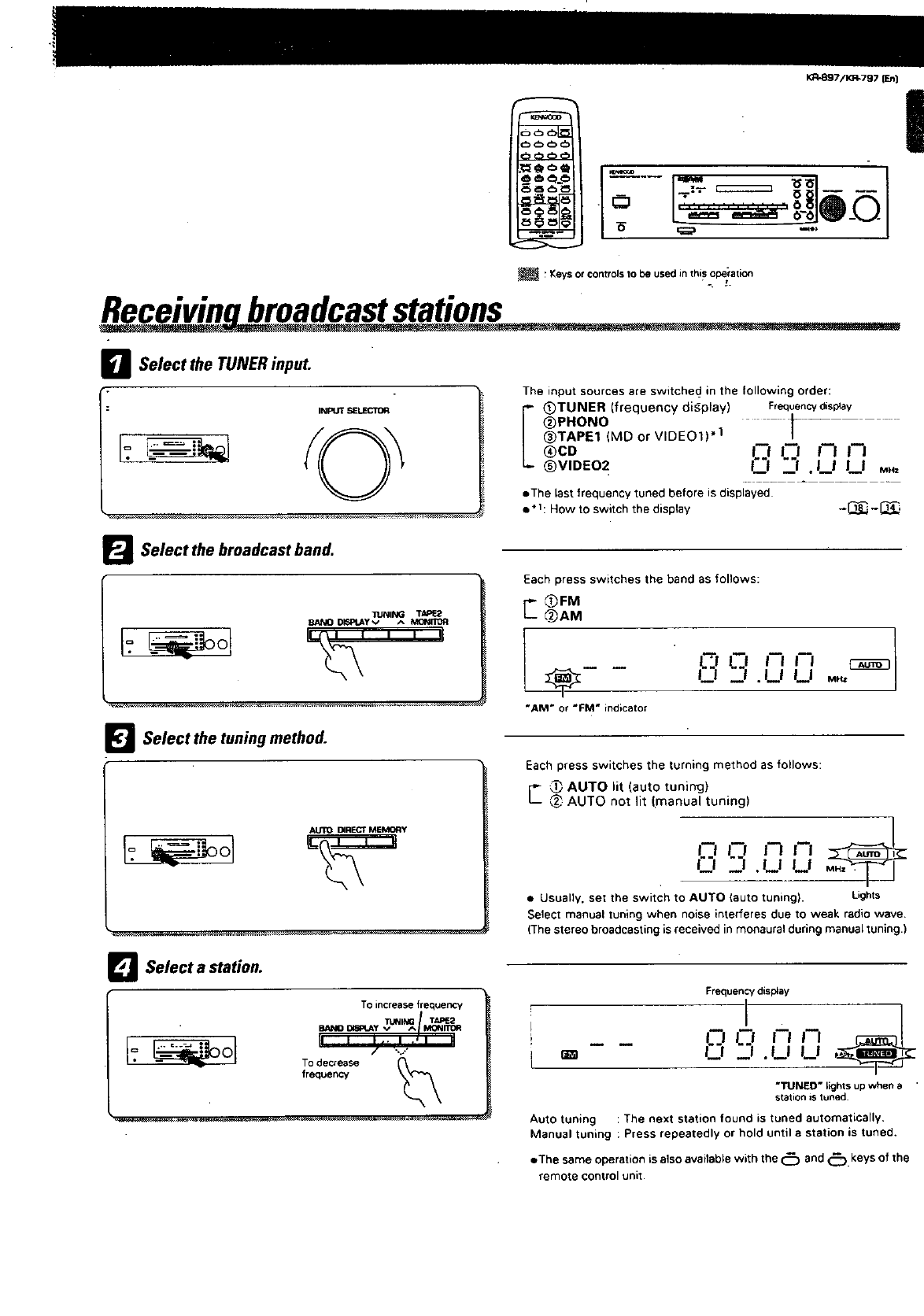
Recelwn broadcaststations
INPUT SELECTOR
nSelect the TUNER input.
[=.
The input sources are switchecl in the following order:
I (_)TUNER (frequency diCplay) Frequencydisplay
_PHONO _- --
_)TAPE1 (MD or VIDE01) .1
(_)CO |-"l J'l |'-I |'7
_VIOEO 2 |'"1 "_..'l !I I I MR,
• The last frequency tuned before is displayed
e*l: How to switch the display -_., -1_..
BSelect the broadcast band.
I=.
1ZJNING TAI_.2
BAh_ D_Ft_Y v A
_l Select the tuning method.
I=
Each press switches the band as follows:
_jFM
@jAM
"AM" or"FM" indicator
--! .L! LI ..,
Each press switches the turning method as follows:
r'- _ AUTO lit (auto tuning)
L_ AUTO not lit (manual tuning)
3
L-.!!--| n N
L! _; .LI U
• Usually. set the switch to AUTO (auto tuning). Lights
Select manual tuning when noise interferes due to weak radio wave.
(The stereo broadcasting is received in monaural during manual tuning.)
_] Select a station.
I=.
Toincreasefrequency
To decrease _
rreque_
Frequencydisplay
1"7 _l !'-| i-I
!22|J.LI U
"I_NED" lights up when a
station is tuned.
Auto tuning :The next station found is tuned automatically.
Manual tuning : Press repeatedly or hold until a station is tuned.
•The same operation is also available with the (_ and (_ keys of the
remote control unit.
KFI-SB7/KR-797 (En)
-1
:Keys or controls to be used in this operation
its
•statio
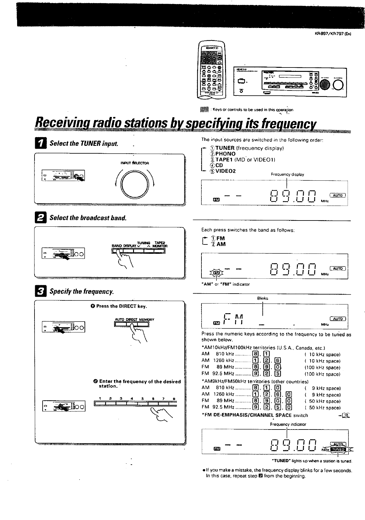
DSelect the TUNER inpuL
INPUT_UEC10R
The _nput sources are switched in the following order:
I TUNER freouency display)
_,PHONO "
_TAPE1 (MD or VIDEO1)
®CD
_VIDEO2 Frequency display
................... i 7
-- - LJ LJ in _n _
F_ Select the broadcast band.
TUNING TARE2
BAND DiSPt_yv ^Md]MTOR
_] Specify the frequency.
0 Press the DIRECT key.
AUTO DIRECT MEMORY
OEnter the frequency of the desired
station.
123 45878
!i , i i ' I _1 I
Each press switches the band as follows:
_" _FM
_AM
r _
I o iT ,n
"AM" or "FM" indicator
Blinks
-- MHz
Press the numeric keys according to the frequency to be tur_ed as
shown below.
*AM10kHz/FM100kHz territories (U.S A., Canada. etc.)
AM 810kHz ............ [_]. [] (10 kHzspace)
AM 1260kHz ............ [_], [_. [] (10kHzspace)
FM 89 MHz ............ r_, []. [] (100 kHz space)
FM 92.5 MHz ............ [_], r_, [] (!00 kHz space)
*AM9kHz/FM50kHz territories (other countries)
AM 810 kHz ............ [_, [_], [] (9 kHz space)
AM 1260kHz............[]._ [].[] (gkHzsp_co)
FM B9MHz ............[]. [], []. [] (50kHzspace)
FM 92,5 MHz ............ [], [], []. [] ( 50 kHz space)
*FM DE-EMPHASIS/CHANNEL SPACE switch -_.
Frequency indicator
_n in N mn
F'I "'l. U U
"TUNED" lightsup when astationis tuned.
•If you make amistake, the frequency display blinks for afew seconds.
In this case, repeat step wl from the beginning.
[ oo ....J I_kB97/KR-797 ten}
I--_-'__ _1....
L,,,=_ ,,-,,10o0
_: Keysorcontr_sto be usedinthisoperption
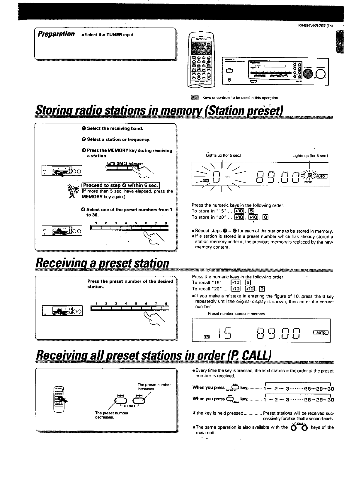
St_o stationsin memo..._:_
Select the receiving band,
Select a station or frequency.
(_ Press the MEMORY key during receiving
astation.
AUTO DIRECT MEMORy
1Proceed to step Owithin 5 sec. I
(If more than 5 sec. have elapsed, press the
MEMORY key again.)
OSelect one of the preset numbers from 1
to 30.
123 45a78
_ghts up (for5sec.)
_--/-/-I-_-
Lights up (for 5 sac.)
0"'a.L L;_.'°
Press the numeric keys in the followingorder.
To store in "15" ... r_. []
To s_orein "20" ... I'_'_. I'_. []
•Repeat steps O - Q for each of the stations to be stored in memory.
elf astation is stored in a preset number which has already stored a
station memory under it, the previous memory is replaced by the new
memory content.
Receivinq a preset station
Press the numeric keys in the following order.
Press the preset number of the desired To recall "15" ... r_, []
station. To recall "20" ... r+_l, {_ol. []
elf you make amistake in entering the figure of 10. press the O key
repeatedly until the original display is shown, then enter the correct
number,
12345 87a
Presetnumberstoredinmemory
I,c 8 _,,_,,_,
_R9 I --
q
Receivin all reset stations in order P. CALL
The preset number
iRcreases.
The p_eset number
docre_lses.
• Everytime the key is pressed, the next station inthe order of the preset
number is received.
II
When you press, (_ key,. ......... 1_ 2 _3........ g8_29--30
t
When you press (_,=_ key........... 1-- 2_3......... 28_29_30
If the key is held pressed ............... Preset stations will be received suc-
cessivelyfor abouthalfe secondeach.
eTha same operation is also available with the _r._ keys of the
main _Jnlt.

KR-eST/K_797(En)
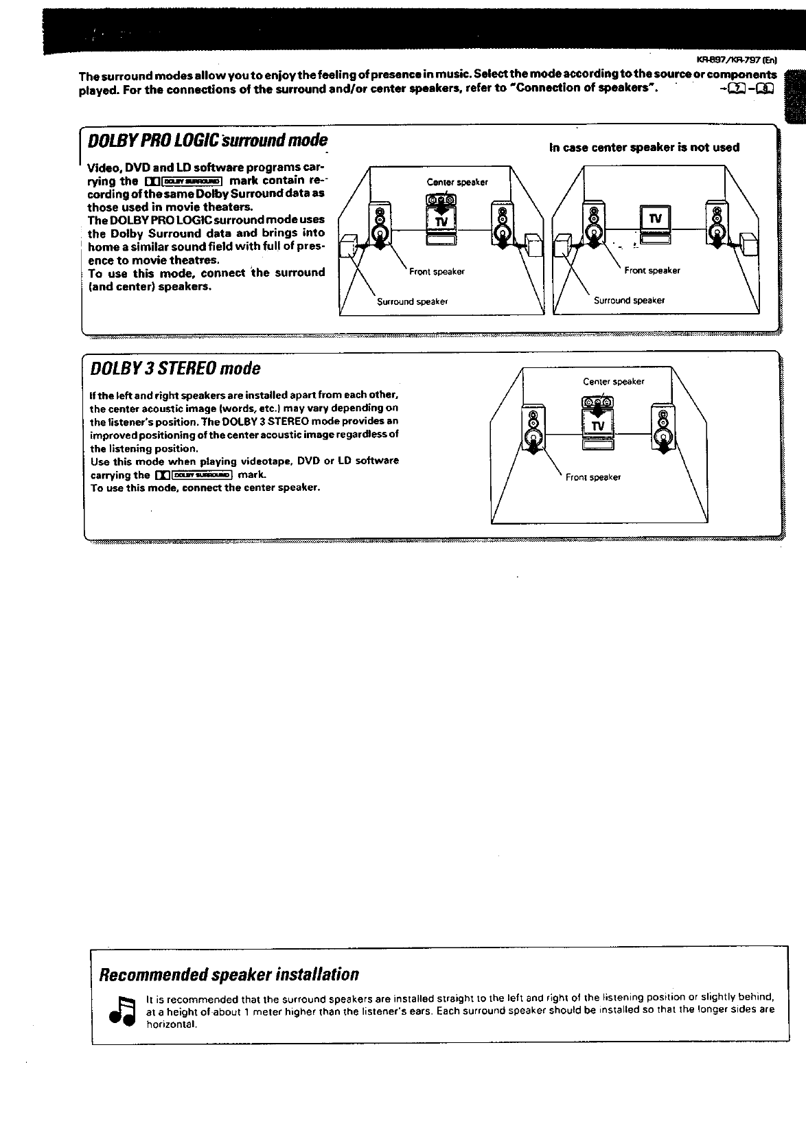
The surround modes allow you to enjoy the feeling of presence in music. Select the mode according to the souse or components
played. For the connections of the surround and/or center speakers, refer to "Connection of speakers-. -P_'I-_
rDOLBY me.,. In case center speaker is not used
PROLOGICsurround dD
Video, DVD and LD software programs car-
rying the ITI_ mark contain re-- Canterspeaker
cording ofthe semo Dolby Surround data as __
those used in movie theaters.
The DOLBY PRO I.OGIC surround mode uses
the Dolby Surround data and brings into
home a similar sound field with full of pres-
ence to movie theatres.
To use this mode, connect the surround ;peaker Front speaker
(and center) speakers.
Surround speaker Surround speaker
I
DOLBY3 STEREOmode
if the left and right speakers are installed apart from each other,
the center acoustic image (words, etc.) may vary depending on
the listener's position. The DOLBY 3 STEREO mode provides an
improved positioning of the center acoustic image regardless of
the listening position.
Use this mode when playing videotape• DVD or LD software
carrying the i-]r][e_J_] mark.
To use this mode, connect the center speaker.
Center speaker
®
Fronl speB_er \
lRecommended speaker installation
It is recommended that the surround speakers are installed straight to the left and right of the listening position or slightly behind,
at a height of about 1 meter higher than the listener's ears. Each surround speaker should be installed so that the longer sides are
horizontal.
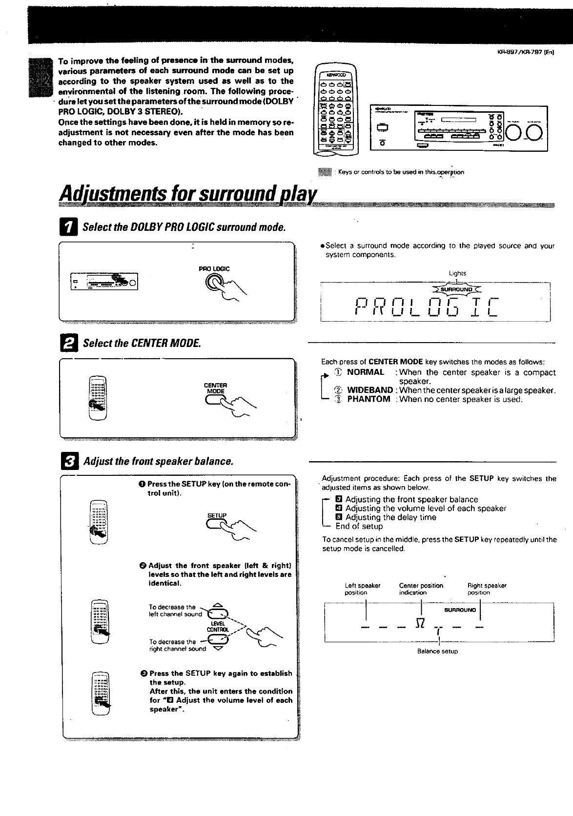
Io improve the feeling of presence in the surround modes,
various parameters of each surround mode can be set up
according to the speaker system used as well as to the
environmental of the listening room. The following proce-
•dure let youset theparametersofthesurroundmode (DOLBY"
PRO LOGIC, DOLBY 3 STEREO).
Once the settings have been done, it is held in memory so re-
adjustment is not necessary even after the mode has been
changed to other modes.
KR897/K_7971En)
:Keys or controls to be used in this.o_oerption
Ad'ustmeMs for surrou, d lay
DSelect the DOLBY PRO LOGIC surround mode.
pRO LOGIC
1=.
• Select a surround mode according to the p}ayed source and your
system components•
I
i
I
L
Ligh{s
LJ[.t r i i i J i T J-
U L U _J i L
Ig
Select the CENTER MODE.
Eachpress of CENTERMODE key switchesthe modes as follows:
NORMAL :When the center speaker is a compact
_" speaker•_, WlDEBAND :Whenthecenterspeakerisalargespeaker.
PHANTOM :When no center speaker is used.
_l Adjust the front speaker balance.
0 Press the SETUP key (on the remote con-
trol unit),
_TUP
OAdjust the front speaker (left & right)
levels so that the left and right levels are
identical•
To decrease the
left channel sound_
LEVEL _;,
CONTROL1"
To decrease the __'_
right channef sound
(_ Press the SETUP key again to establish
the setup.
After this, the unit enters the condition
for "El Adjust the volume level of each
speaker'.
Adjustment procedure: Each press of the SETUP key switches the
adjusted items as shown below,
[] Adjusting the front speaker balance
FI Adjusting the volume level of each speaker
[] Adjusting the delay time
End of setup
To cancel setup inthe middle, press the SETUP key repeatedly until the
setup mode is cancelled,
Left speaker Center position Right speaker
position indication position
I i su-ol
I
I
Salance setup
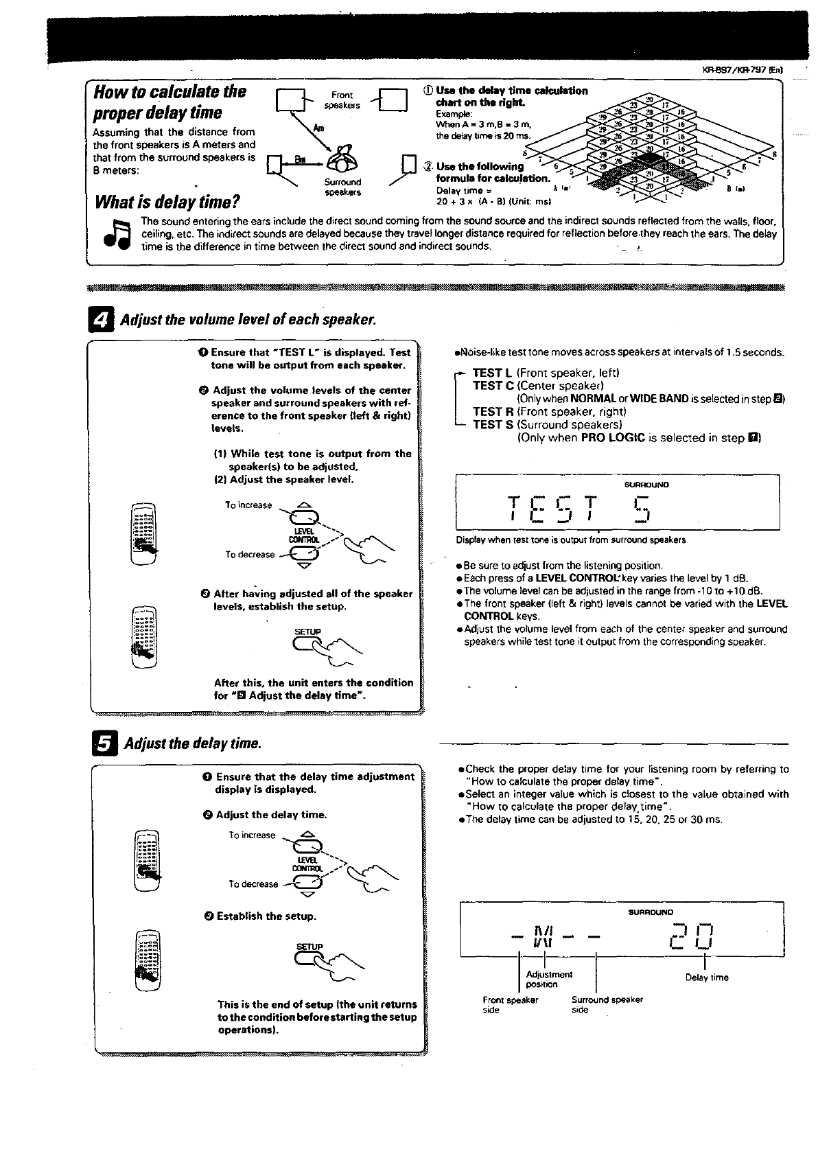
•How to calculate the Fro_,
properBdelay time __s
Assuming that the distance from
the front speakers is A meters and
that from the surround speakers is
meters: _Su.o_nd _"
speakers
What is delay time?
Use the delay time calculation
chart on the right.
Example:
WhenA= 3 m.B = 3 m,
thedelaytimeis20 ms,
_, Use the following
formula for eal_letion.
Delay time = _i=,
20+3x (A-B)(Unit:rnsl
KR-Bg7/KJ_797 [Enl
The sound entering the ears include the direct soundcoming from the soundsource and the indirect sounds reflected from the walls, floor,
ceiling, etc. The indirect sounds are delayed because they travel longer distance required for reflection before .they reach the ears. The delay
time is the difference in time between the direct sound and indirectsodnds. -. _.
_l Adjust the volume level of each speaker.
OEnsure that "TEST L" is displayed. Test
tone will be output from each speaker.
OAdjust the volume levels of the center
speaker and surround speakers with ref-
erence to the front speaker (left & right)
levels.
(1) While test tone is output from the
speaker(s) to be adjusted.
(2] Adjust the speaker level.
"tOincrease _ •
To0--.e
(_ After having adjusted all of the speaker
levels, establish the setup.
SETUP
After this, the unit enters the condition
for -I_1Adjust the delay time".
e_oise-like test tone moves across speaker• at intervals of 1.5 seconds.
IEST L (Front epeaker, left)
TEST C (Center speaker)
(Onlywhen NORMAL or WIDE BAND is selected instep m)
TEST R (Front speaker, tight)
TEST S (Surround speakers)
(Only when PRO LOGIC is selected in step roll)
ISURROUND
TF,- TC
I-- "'l I
Displaywhentesttone isoutputfrom surroundspeakers
• Besure to adjust from the listening position.
•Each press of aLEVEL CONTROL" key varies the level by 1 dB.
•The volume level can be adjusted in the range from -10 to +10 dB.
•The front speaker (left & right) levels cannot be varied with the LEVEL
CONTROL keys.
•Adjust the volume level from each of the center speaker and surround
speakerswhile test tone itoutput from the correspoeding speaker.
_Adjust the time.
delay
OEnsure that the delay time adjustment
display is displayed.
OAdjust the delay time.
TOincrease __
OONmOLI"
TOdecrease_"
Establish the setup.
_rup
This is the end of setup (the unit returns
to the condition before starting the setup
operations).
•Check the proper de_ay time for your listening room by referring to
"How to calculate the proper delay time".
•Select an integer value which is closest to the value obtained with
"How to calculate the proper delay time'.
• The delay time can be adjusted to 15. 20. 25 or 30 ms.
-- IWI -- --
I/U
--I
Adjustment
position
Front speaker Surround speaker
side side
SURRDUND
J._J
I
Delay time
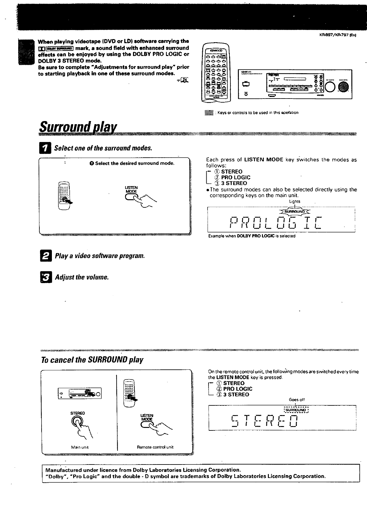
When playing videotape (DVO or LD) software carrying the
rrl[_;_]_] mark, a sound field with enhanced surround
effects can be enjoyed by using the DOLBY PRO LOGIC or
DOLBY 3 STEREO mode.
Be sure to complete "Adjustments for surround play" prior
to starting playback in one of these surround modes.
KR-897/KR-797 [En]
6L",_ __,J'_..J
: Keys or controls to be used in this i_oera_ion
Surround la •
DSelect one of the surround modes.
OSelect the desired surround mode. Each press of LISTEN MODE key s_vitches the modes as
follows:
ESTEREO
_@___'PRO LOGIC
@3 STEREO
eThe surround modes can also be selected directly using the
corresponding keys on the main unit.
Lights
LJ LJ Iil f li '1 r
i l_ LIL LILt .L L
Examprewhen DOLBYPROLOGICisselected
_Play a video software program.
_l Adjust the volume.
Tocancel the SURROUNDplay
STEREO
Main unit Remote control unit
On the remote control unit. the following modes are switched every time
the LISTEN MODE key is pressed.
'-_, STEREO
(_ PRO LOGIC
3 STEREO Goesoff
1..suR..R_.U.N.O..: 7
I- T l- _
"'liF _Li !
Manufactured under licence from Dolby Laboratories Licensing Corporation.
"Dolby', "Pro Logic" and the double -D symbol are trademarks of Dolby Laboratories Licensing Corporation.
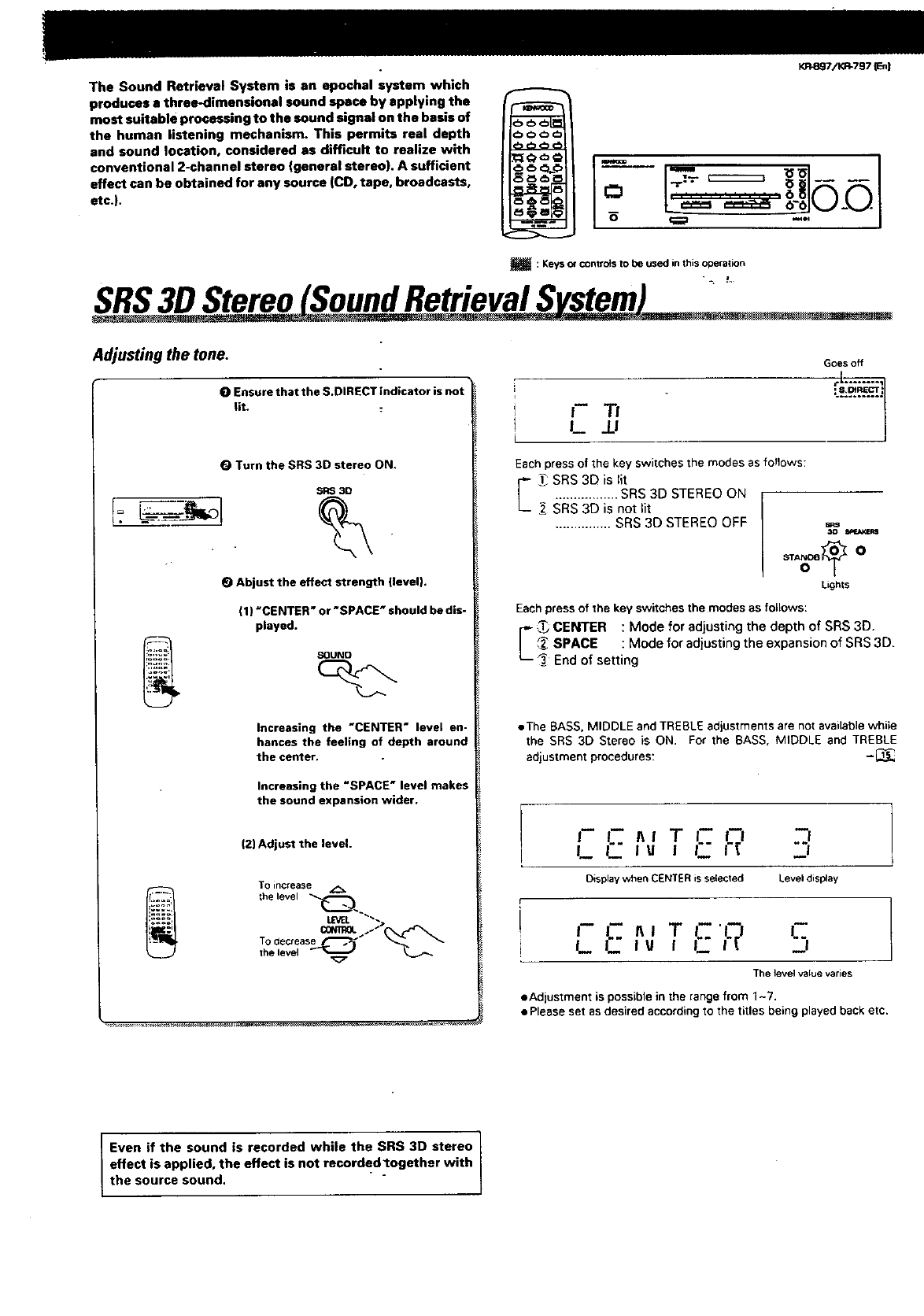
TheSoundRetrievalSystemisanepochalsystemwhich
producesathroe-dimensionalsoundspacebyapplyingthe
mostsuitableprocessingtothesoundsignalonthebasisof
thehumanlisteningmechanism.Thispermitsrealdepth _)_
and sound location, considered as difficult to realize with
conventional 2-channel stereo (general stereo). A sufficient _ _ _L_
effect can be obtained for any source (CD, tape, broadcasts, _ _ _ _
N
etc.}.
KR.4_q7/I_I-797 r:n)
o _°°
: Keys or contro]s to be used in this opera,ion
SRS3D Stereo SoundRetrievalS stem "
Adjusting the tone.
O Ensure that the S,DIRECT indicator is not
Fit.
Turn the SRS 3D stereo ON.
SRe 30
OAbjust the effect strength (level).
(1) "CENTER = or'SPACE" should be dis-
played.
SOUNc_ _
Increasing the "CENTER" level en-
hances the feeling of depth around
the center,
Increasing the "SPACE" level makes
the sound expansion wider.
(2) Adjust the level.
To increase _.
the level _
LEVEL"_'_
TO decrease _
the level
Goes off
rL ........ _1
L_ JJ
l
Each press of the key switches the modes as fo!lows:
['-_ SRS 3[3 is lit
................. SRS 3D STEREO ON
SRS 3D is not lit
............... SRS 3D STEREO OFF Mr 4
Lights
Eachpress of "{hekeyswitchesthemodesas follows:
,_ ENTER : Mode for adjusting the depth of SRS 3D.
SPACE : Mode for adjustingthe expansionof SRS 3D,
End of setting
• The BASS, MIDDLE and TREBLE adjustments are not available while
the SRS 3D Stereo is ON, For the BASS, MIDDLE and TREBLE
adjustment procedures: -13_
l-- C _1 TI-- i--I _i
L L lU ! C I-_" _i
Displaywhen CENTERisselected Leveldisplay
c:.nl T I- 'l;I C
(-.fu I C _i
L_ _
The level value varies
eAdjustment is possible in the range from 1-7.
•Please set as desired according to the titles being played back etc.
Even if the sound is recorded while the SRS 3D stereo I
effect is applied, the effect is not recordedlogether with
the source sound.
KR-eS7/KR-797 ten I
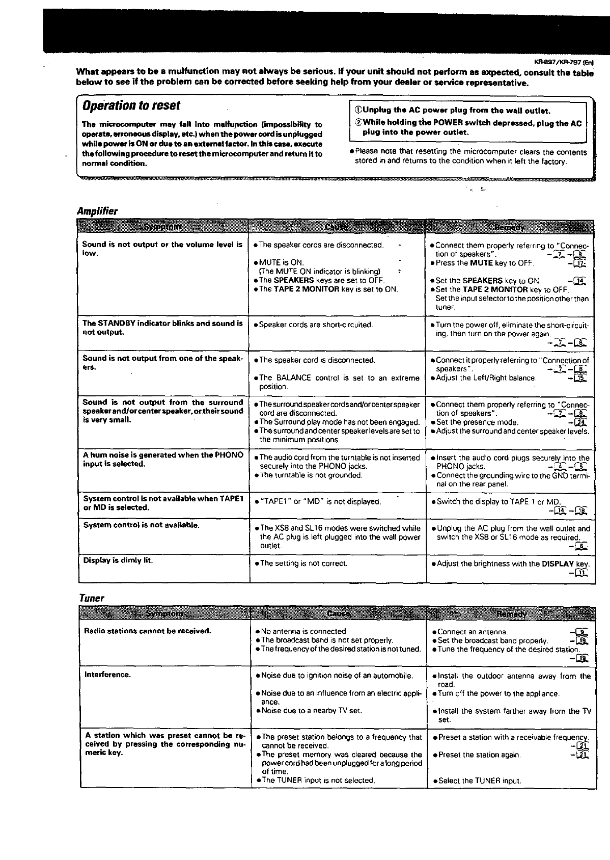
What appears to be a mulfunction may not always be serious. If your Unit should not perform as expected, consult the table
below to see if the problem can be corrected before seeking help from your dealer or service representative.
Operation to reset
The microcomputer may fall into msifupction (impossibility to
Operate, erroneous display, etc.) when the power cord is unplugged
while powey is ON or due to an extsrnM factor. Inthis case, execute
the following prQcedure to reset the microcompute¢ and return itto
normal condition.
_Unplug the AC power plug from the wall outlet.
L_While holding the POWER switch depressed, plug the AC
plug into the power outlet.
• Please note that resetting the microcomputer clears the contents
stored in and returns to the condition when it left the factory•
"L
Amplifier
Sound is not output or the volume level is
low. • The speaker cordsare disconnected• •Connect them properly refemng to "Connec-
• MUTE is ON.
(The MUTE ON indicator is blinking) :
•The SPEAKERS keys are set to OFF.
•The TAPE 2 MONITOR key is set to ON
eqnof speakers". -._-_8
•Press the MUTE key to OFF -_
• Set the SPEAKERS key to Ok: -_
• Set the TAPE 2 MONITOR key to OFF.
Set the input selector to the position other than
tuner
The STANDBY indicator blinks and sound is • Speaker cords are short-circuited, eTum the power off. eliminate the short-ciicuit-
not output, ing, then turn on the power again
Sound is nut output from one of the speak- • The speaker cord is disconnected. • Connectitproperlyreferringto "Connection of
ers. speakers". -.._ --_
•The BALANCE control is set to an extreme •Adjust the Left/Right balance.
position.
Sound is not output from the surround •Thesurroundspeakercordsand/orcenterspeaker •Connect them properlyreferbngto "Connec-
speakerand/orcenterspeakeroortheirsound cord are disconnected, tion of speakers". -,_._.7-_
is very small. •The Surround playmode hasnot been engaged. • Set the presence mode. -
•The surroundand center speaker levelsare set to • Adiust the surroundand center spoakerlevels.
the minimum positions•
A hum noise is generated when the PHONO •The audio cordfrom the turntable isnot inserted • Insert the audio cord plugs securely_nt othe
input is selected, securely into the PHONO jacks. PHONO jacks. -;4___
•The turntable is not grounded. •Connect the grounding wire to the GNb termi-
nal on the rear panel.
System control is not available when TAPE1 •"TAPEr" or "MD" is not displayed. •Switch the display to TAPE 1 or MD.
or MD is selected. -1_ __
System control is not available. • The XS8 and SLt 6 modes were switched while • Unplug the AC plug from the wall cutlet and
the AC plug is left plugged into the walt power switch the XS8 or SL16 mode as required.
outlet• -t_
Display is dimly lit. •The setting is not correct. •Adiust the brightness with the DISPLAy key.
Tuner
Radio ctation$ cannot be received.
Interference.
A station which was preset cannot be re-
ceived by pressing the corresponding nu-
meric key.
•NO antenna is connected.
• The broadcast band is not set properly.
•The frequency of the desired station is not tuned.
•Noise due to ignition noise of an automobile.
•Noise due to an influence from an electric appli-
ance.
• Noise due to a nearby "IV set.
•The preset station belongs to afrequency that
cannotbe received•
• The preset memory was cleared because the
power cordhadbeen unplugged for a Ior',gperiod
of time.
•The TUNER input _snot selected.
•Connect anantenna. -'[9_1_
•Set the broadcast band property.
• Tune the frequency of the desired station.
• install the outdoor antenna away from the
road.
• Turn off the power tc the app{iance.
•Install the system farther away from the TV
set.
• Preset astation with a receivable freque_
• Preset the station again• -t_J._
•Select the TUNER input.
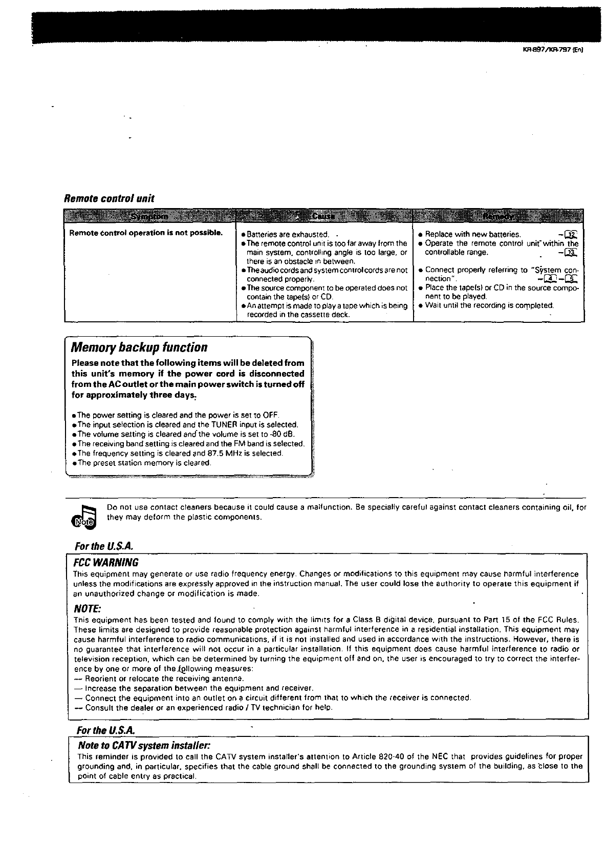
Remote control unit
Remote Control operation is not possible. • Batteries are exhausted..
• The remote control unit is too far away from the
main system, controlhng angle is too large, or
there is an obstacle m between.
• The audio cords end system control cords are not
connected properly.
• The source component to be operated does not
contain the tape(s) or CD
• An attempt is made to play atape which is being
recorded in the cassette deck.
• Replace with new batteries. -_
• Operate the remote control unit-within the
controllable range. -_
• Connect properly referring to "S_'stem con-
nection ", --_ -L_s"
• Place the tape(s) or CD in the source compo-
nent to be played.
• Wait until the recording is cor_pleted.
Memory backup function
Please note that the following items will be deleted from
this unit's memory if the power cord is disconnected
from the AC outlet or the main power switch is turned off
for approximately three days:
• The power setting is cleared and the power is set to OFF.
• The input selection is cleared and the TUNER input is selected.
• The volume setting is cleared and'the volume is set to -80 dB.
•The receiving band setting is cleared and the FM band is selected.
• The frequency setting is cleared and 87.5 MHz is selected.
• The preset station memory is cleared.
_e Do not use contact cleaners because it could cause a malfunction. Be specially careful against contact cleaners containing oil, for
they may deform the plastic components.
Forthe U.S.A.
FCC WARNING
This equipment may generate or use radio frequency energy. Changes or modifications to this equipment may cause harmful interference
unless the modifications are expressly approved in the instruction manual. The user could lose the authority to operate this equipment if
an unauthorized change or modification is made
NOTE:
This equipment has been tested and found to comply with the limits for a Class B digital device, pursuant to Part 15 of the FCC Rules.
These limits are designed to provide reasonable protection against harmful interference in a residential installation. This equipment may
cause harmful interference to radio communications, if it is not installed and used in accordance with the instructions. However, there is
no guarantee that interference will not occur in aparticular installation. If this equipment does cause harmful interference to radio or
television reception, which can be determined by turning the equipment off and on. the user is encouraged to try to correct the interfer-
ence by one or more of the IL£11owing measures:
-- Reorient or relocate the receiving antenna.
-- Increase the separation between the equipment and receiver.
-- Connect the equipment into an outlet on a circuit different from that to which the receiver is connected.
-- Consult the dealer or an experienced radio /TV technician for help.
For the U.S.A.
Note to CATVsystem installer:
This reminder is provided to call the CATV system installer's attent,on to Article 820-40 of the NEC that provides guidelines for proper
grounding and. in particular, specifies that the cable ground shall be connected to the grounding system of the building, as _lose to the
point of cable entry as practical.
|K-R.887/KR-797 _n)
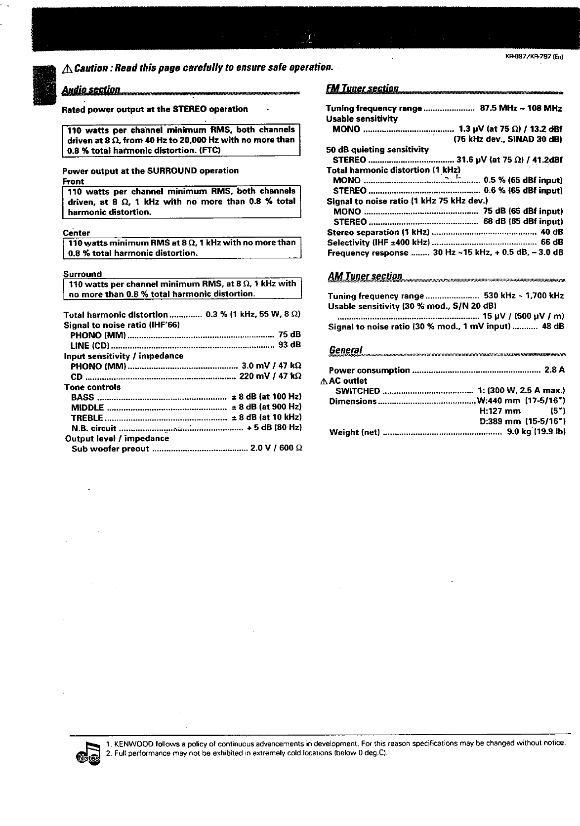
A_Caution: Read this page carefully to ensure safe operation.
• . __ _-
Rated power output at the STEREO operation
110 watts per channel minimum RMS, both channels
driven at 8 z_, from 40 Hz to 20,000 Hz with no more than
t0.8 % total harmonic distortion. (FTC)
Power output at the SURROUND operation
Front
110 watts per channel minimum RMS, both channels
driven, at 8 _, 1 kRz with no more than 0.8 % total
harmonic distortion.
Center
110 watts minimum RMS at 8 z'Z,1 kHz with no more than |
g.0 % total harmonic distortion. J
Tuning frequency range ...................... 87.5 MHz ~ 108 MHz
Usable sensitivity
MONO ....................................... 1,3 pV (at 75 [2) /13.2 dBf
(75 kHz dev,, SINAD 30 dB)
50 dB quieting sensitivity
STEREO ..................................... 31.6 pV {at 75 _) /41.2dBf
Total harmonic distortion (1 kHz}
MONO .......................... :.,....i.':..,_,........ 0.5 % (65 dBf input)
STEREO ................................................ 0.6 % {65 dBf input)
Signal to noise ratio (1 kHz 75 kHz dev.)
MONO ................................................. 75 dB (6S dBf input)
STEREO ............................................... 68 dB (65 dBf input)
Stereo separation (1 kHz) ............................................. 40 dB
Selectivity (IHF ±400 kHz) ............................................. 66 dB
Frequency response ........ 30 Hz ~15 kHz, + 0.5 dB, -3.0 dB
Surround
110 watts per channel minimum RMS, at 8 _, 1 kHz with
no more than 0.8 %total harmonic distortion. I
Total harmonic distortion .............. 0.3 % (1 kHz, 55 W, 8 _)
Signal to noise ratio (IHF'66)
PHONO (MM) ............................................................... 75 dB
LINE (CD) ...................................................................... 93 dB
Input sensitivity /impedance
PHONO (MM) ............................................... 3.0 mV /47 Ir_
CD ................................................................ 220 mV /47 k_
Tone controls
BASS ....................................................... ± 8 dB {at 100 Hz)
MIDDLE ................................................... = 8 dB (at 900 Hz)
TREBLE .................................................... ± 8 dB (at 10 kHz)
N.B. circuit ................... ._..:._...:-, ................... + 5 dB (80 Hz)
Output level /impedance
Sub woofer preout ......................................... 2.0 V /600 _Z
Tuning frequency range ....................... 530 kHz - 1,700 kHz
Usable sensitivity (30 % mod., SIN 20 dR)
............................................................. 15 pV /(500 pV /m}
Signal to noise ratio (30 % rood., 1mV input) ........... 48 dB
Power consumption ....................................................... 2.8 A
/kAC outlet
SWITCHED ....................................... 1:(300 W, 2.5 A max.)
Dimensions .......................................... W:440 mm (17-5116")
H:127 mm (5")
D:389 mm (15-5/16"}
Weight (net) ................................................... 9.0 kg (19.9 Ib)
_s .KENWOOD follows a policyof continuous advancements indevelopment, Forthis reason specifications may be changed without notice•
2. Full performance may not be exhibited in extremely cold locations (below 0 deg.C)
L_ Caution : Read this page carefully to ensure safe operatioh. _7/KR-797 JEnJ
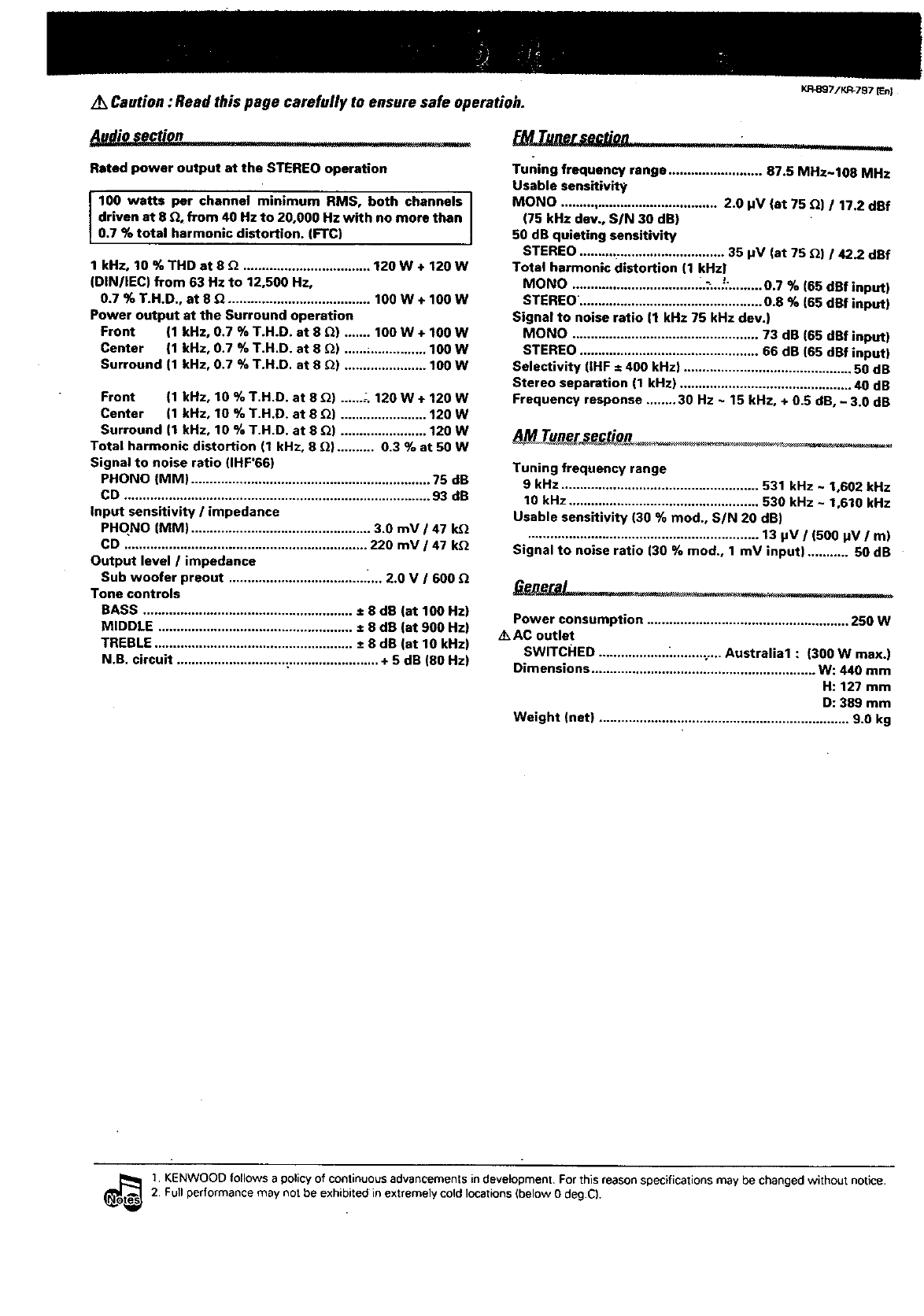
Audio section i'll
Rated power output at the STEREO operation
100 watts per channel minimum RMS, both channels
driven at 8 _, from 40 Hz to 20,000 Hz with no more than
0.7 % tota harmon c distortion. (FTC)
1 kHz, 10 %THD at 8 _ .................................. 120W+ 120W
(DIN/IEC) from 63 Hz to 12,500 Hz,
0.7 % T.H.D., at 8 _'1...................................... 100W+10OW
Power output at the Surround operation
Front (1 kltz, 0.7 % T.H.D. at 8 _) ....... 100 W + 100 W
Center (1 kHz, 0.7 % T.H.D. at 8 [Z) ......_............... 100W
Surround (1 kHz, 0.7 %T.H.D. at 8 _) ...................... 100 W
Front (1 kHz, 10 % T.H.D. at 8 _) ...... -. 120W+ 120 W
Center (1 kHz, 10 % T.H.D. at 8 _) ....................... 120W
Surround (1 kHz, 10 % T.H.D. at 8 _) ....................... 120 W
Total harmonic distortion (1 kHz, 8 _} .......... 0.3 % at 50 W
Signal to noise ratio (IHF'66)
PHONO (MM) ................................................................ 75 dB
CD .................................................................................. 93 dB
Input sensitivity /impedance
PHO,NO (MM) ................................................ 3.0 mV /47 kQ
CD ................................................................. 220 mV /47 k_
Output level /impedance
Sub woofer preout ..................................... _... 2.0 V /600
Tone controls
BASS ........................................................ ± 8 dB (at 100 Hz}
MIDDLE .................................................... ± 8 dB (at 900 Hz)
TREBLE ..................................................... ± 8 dB (at 10 kHz)
N.B. circuit ............................. :........................ + 5 dB (80 Hz)
_Tuner section
Tuning frequency range ......................... 87.5 MHz~lO8 MHz
Usable sensitivity
MONO .......................................... 2.0 pV (at 75 Q) /17.2 dBf
(75 kHz dev., S/N 30 dg)
50 dB quieting sensitivity
STEREO ...................................... 35 pV (at 75 Q) /42,?.dRf
Total harmonic distortion (1 kHz)
MONO .................................. _.:;.._:......... 0.7 % (65 dBf input)
STEREO. ................................................ 0.8 % (65 dBf input)
Signal to noise ratio (1 kHz 75 kHz dev.)
MONO .................................................. 73 dB (65 dBf input)
STEREO ................................................ 66 dB (65 dBf input)
Selectivity (IHF =400 kHz) ............................................. 50 dB
Stereo separation (1 kHz) .............................................. 40 dB
Frequency response ........ 30 Hz ~ 15 kHz, + 0.5 dB, - 3.0 dB
_. T_p_eJ_£ ............
Tuning frequency range
9 kHz ..................................................... 531 kHz ~ 1,602 kHz
10 kHz ................................................... 530 kHz ~ 1,610 kHz
Usable sensitivity (30 % mud., S/N 20 dB)
.............................................................. 13 pV /(500 pV /m)
Signal to noise ratio (30 % mud., 1 mV input) ........... 50 dB
Power consumption ...................................................... 250 W
/k AC outlet
SWITCHED ................... _........ :.... Australia1 : (300 W max.)
Dimensions ............................................................ W: 440 mm
H: 127 mm
D: 389 mm
Weight (net) ................................................................... 9.0 kg
_s . KENWOOO follows a policy of continuous advancements in development For this reason specifications may be changed without notice.
2. Full performance may not be exhibited in extremely cold locations (below 0 deg.C),
|KR_97/KR-797 [En]
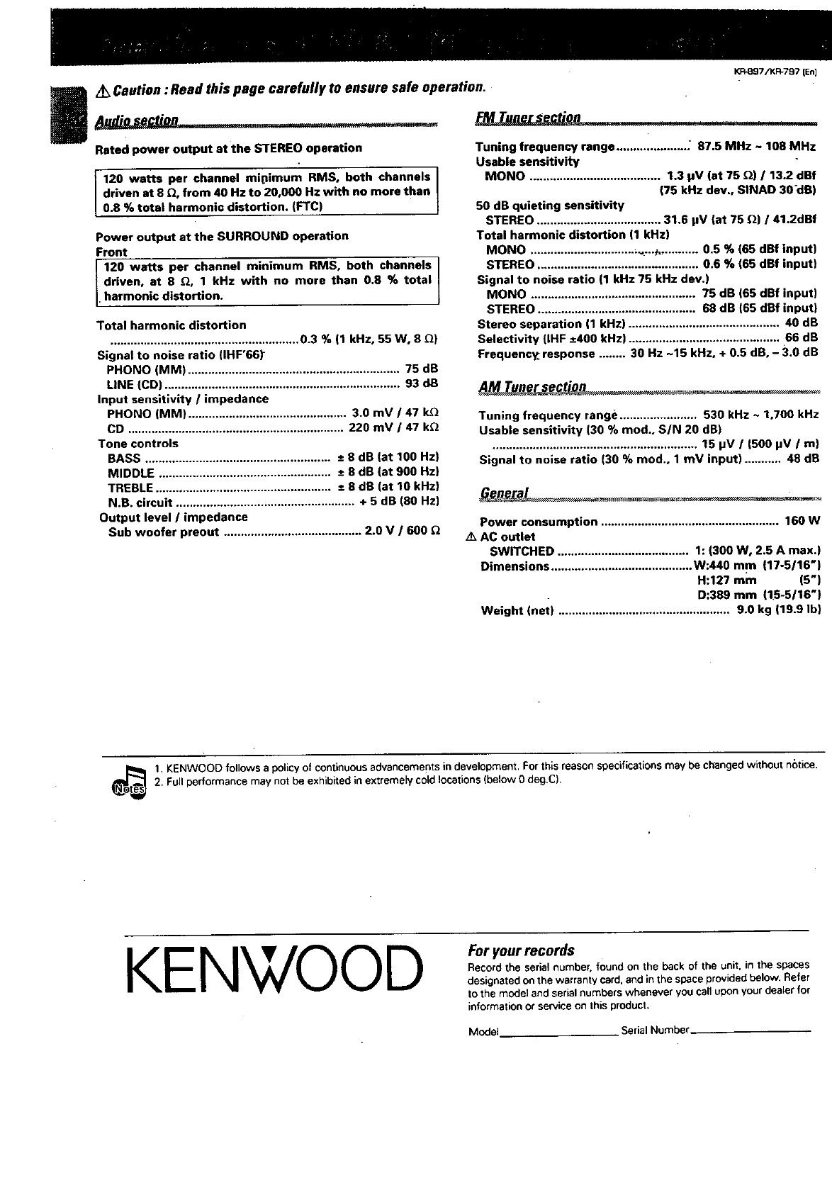
Z_ Caution : Read this page carefully to ensure safe operation.
Rated power output at the STEREO operation
120 watts per channel mipimum RMS, both channels
driven at 8 _, from 40 Hz to 20,000 Hz with no more than
0.8 % total harmonic distortion. (FTC)
Power output at the SURROUND operation
Front
120 watts per channel minimum RMS, both channels
driven, at 8 _, 1 kHz with no more than 0.8 %total
• harmonic distortion.
Total harmonic distortion
........................................................ 0.3 % (1 kHz, 55 W, 8 _)
Signal to noise ratio (IHF'66_
PHONO (MM) ............................................................... 75 dB
LINE (CD) ...................................................................... 93 dB
Input sensitivity /impedance
PHONO (MM) ............................................... 3.0 mV /47 k_
CD ................................................................ 220 mV /47 k_
Tone controls
BASS ....................................................... ± 8 dB (at 100 Hz)
MIDDLE ................................................... ± 8 dB (st 900 Hz)
TREBLE .................................................... ± 8 dR (at 10 kHz)
N.R. circuit ..................................................... + 5 dB (80 Hz)
Output level /impedance
Sub woofer preout ......................................... 2.0 V /600
Tuning frequency range ..................... ; 87.5 MHz ~ 108 MHz
Usable sensitivity
MONO ....................................... 1.3 pY (at 75 _) /13.2 dBf
(75 kHz dev., SINAD 30-dR)
50 dB quieting sensitivity
STEREO ..................................... 31.6 pY (at 75 Q) /41.2dBf
Total harmonic distortion (1 kHz)
MONO ................................ _..._,........... 0.5 % (65 dBf input)
STEREO ................................................ 0.6 % (65 dSf input)
Signal to noise ratio (1 kHz 75 kHz dev.)
MONO ................................................. 75 dB (65 dBf input)
STEREO ............................................... 68 dB (65 dBf input)
Stereo separation (1 kHz) ............................................. 40 dB
Selectivity (IHF ±400 kHz) ............................................. 66 dB
Frequency. response ........ 30 Hz -15 kHz, + 0.5 dB, - 3.0 dB
Tuning frequency range ....................... 530 kHz ~1,700 kHz
Usable sensitivity (30 % rood., S/N 20 dB)
............................................................. 15 pV /(500 pV /m)
Signal to noise ratio (30 % rood., 1mV input) ........... 48 dB
Power consumption ..................................................... 160 W
A_ AC outlet
SWITCHED ....................................... 1:(300 W, 2.5 A max.)
Dimensions .......................................... W:440 mm (17-5/16")
H:127 mm (5")
D:389 mm (15-6/16")
Weight (net) ................................................... 9.0 kg |19.9 Ib)
1. KENWOOD follows apolicy of continuous advancements in development. Forthis reason specifications may be changed without netice.
_s 2. Full performance not be exhibited in extremely cold locations (below 0 deg.C).
may
KEN',7,/OODFor your records
Record the serial number, found on the beck of the unit. in the spaces
designated on the warranty card. and in the space provided below. Refer
to the model and serial numbers whenever you call upon your dealer for
information or service on this product.
Model. Serial Number
