Kenwood Stereo Receiver Ts 2000 Users Manual 2000_2000X_B2000
TS-2000 to the manual f36a08b1-386c-4fa0-b38f-e83128ed087d
2015-01-23
: Kenwood Kenwood-Kenwood-Stereo-Receiver-Ts-2000-Users-Manual-264260 kenwood-kenwood-stereo-receiver-ts-2000-users-manual-264260 kenwood pdf
Open the PDF directly: View PDF ![]() .
.
Page Count: 152 [warning: Documents this large are best viewed by clicking the View PDF Link!]
© B62-1221-50 (K, E)
09 08 07 06 05
ALL MODE MULTI-BAND TRANSCEIVER
TS-2000
TS-2000X
TS-B2000
INSTRUCTION MANUAL
NOTIFICATION
This equipment complies with the essential requirements of Directive 1999/5/EC.
The use of the warning symbol means the equipment is subject to restrictions of
use in certain countries.
This equipment requires a licence and is intended for use in the countries as
below.
TAEBKDIFRFEDRGSIEITIIL
ULLNONTPSEESHCBGYCZCEE
UHVLTLTMLPKSISGBOR
6613OSI

i
THANK YOU
THANK YOU
Thank you for choosing this KENWOOD TS-2000(X)/
TS-B2000 transceiver. It has been developed by a
team of engineers determined to continue the
tradition of excellence and innovation in KENWOOD
transceivers.
This transceiver features dual Digital Signal
Processing (DSP) units to process IF and AF signals.
By taking maximum advantage of DSP technology,
the TS-2000(X)/ TS-B2000 gives you enhanced
interference reduction capabilities and improves the
quality of audio that you transmit without installing
additional analog filters. You will notice the
differences when you fight QRM and QRN. As you
learn how to use this transceiver, you will also find
that KENWOOD is pursuing “user friendliness”. For
example, each time you change the Menu No. in
Menu mode, you will see scrolling messages on the
display that tell you what you are selecting.
Though user friendly, this transceiver is technically
sophisticated and some features may be new to you.
Consider this manual to be a personal tutorial from
the designers. Allow the manual to guide you through
the learning process now, then act as a reference in
the coming years.
FEATURES
• All mode operation from HF to 1.2 GHz (TS-2000/
TS-B2000 Optional) amateur radio band with DSP
functions.
• Dual high speed Digital Signal Processing (DSP)
units.
• Adjustable DSP filter frequencies.
• High speed Digital Automatic Gain Control (AGC).
• A second independent sub-receiver for the 144 MHz
and 430 (440) MHz bands (FM and AM mode only).
• A built-in Antenna Tuner for HF/ 50 MHz band.
• A built-in 9600/ 1200 bps TNC for DX Packet
Cluster Tune (P.C.T.) and Sky Command II+
operations.
• DX Packet Cluster Tune (P.C.T.) for DX hunting.
• Instant Satellite communication key.
• A razor sharp DSP filter up to 50 Hz for CW
operation.
SUPPLIED ACCESSORIES
After carefully unpacking the transceiver, identify the
items listed in the table. We recommend you keep
the box and packing material below in case you need
to repack the transceiver in the future.
enohporciMXX-2530-19T11
elbacrewopCDXX-7513-03E11
gulpNIDnip-7XX-1570-70E11
gulpNIDnip-8XX-1580-70E11
gulpNIDnip-31XX-1531-70E11
(25 A)esuFXX-1352-50F11
(4 A)esuFXX-7204-60F11
teSwercSXX-4202-99N11
034-BMrofrecapSXX-8962-11G44
retlifeniL
1
XX-8041-97L11
dnaBgniniateR
1
XX-7030-16J11
MOR-DCXX-3210-39T–1
launaMnoitcurtsnIXX-1221-26B11
kcolB/citamehcS smargaiD
XX-4160-25B XX-6160-25B
XX-8160-25B XX-7160-25B 11
dracytnarraW
XX-9640-64B )epyt-K( XX-0130-64B )sepyt-EllA(
11
Accessory Part Number Quantity
TS-2000
TS-2000X TS-B2000
or
1E and E2-type only
WRITING CONVENTIONS FOLLOWED
The writing conventions described below have been
followed to simplify instructions and avoid
unnecessary repetition.
noitcurtsnI oDottahW
sserP ]YEK[]YEK[ ]YEK[ ]YEK[]YEK[ .esaelerdnasserP YEKYEK YEK YEKYEK .
sserP ]2YEK[+]1YEK[]2YEK[+]1YEK[ ]2YEK[+]1YEK[ ]2YEK[+]1YEK[]2YEK[+]1YEK[ .
dlohdnasserP 1YEK1YEK 1YEK 1YEK1YEK ,nwod
sserpneht 2YEK2YEK 2YEK 2YEK2YEK eraerehtfI. dnasserp,syekowtnahterom litnunrutniyekhcaenwoddloh .desserpneebsahyeklanifeht
sserP ]1YEK[]1YEK[ ]1YEK[ ]1YEK[]1YEK[ ,]2YEK[]2YEK[ ]2YEK[ ]2YEK[]2YEK[ .sserP 1YEK1YEK 1YEK 1YEK1YEK ,yliratnemom
esaeler 1YEK1YEK 1YEK 1YEK1YEK sserpneht, 2YEK2YEK 2YEK 2YEK2YEK .
sserP ][+]YEK[][+]YEK[ ][+]YEK[ ][+]YEK[][+]YEK[ .
,FFOrewopreviecsnartehthtiW dlohdnasserp YEKYEK YEK YEKYEK hctiwsneht, ybrewopreviecsnartehtNO gnisserp ][][][ ][][.)REWOP(

ii
MODELS COVERED BY THIS MANUAL
The models listed below are covered by this manual.
TS-2000: HF/ VHF/ UHF All-mode Multi-band
Transceiver
TS-2000X: HF/ VHF/ UHF/ 1.2 GHz All-mode
Multi-band Transceiver
TS-B2000: HF/ VHF/ UHF All-mode Multi-band
Transceiver
As for TS-B2000, refer to the on-line help for
information on how to operate and control the
transceiver. Refer to pages 2, 3, and 13 for the
installation and information on the connectors.
MARKET CODES
K-type: The Americas
E-type: Europe
E2-type: Spain
The market code is shown on the carton box.
Refer to the specifications {page 105} for the
information on available operating frequencies.
NOTICE TO THE USER
One or more of the following statements may be
applicable for this equipment.
FCC WARNING
This equipment generates or uses radio frequency energy.
Changes or modifications to this equipment may cause harmful
interference unless the modifications are expressly approved in
the instruction manual. The user could lose the authority to
operate this equipment if an unauthorized change or
modification is made.
INFORMATION TO THE DIGITAL DEVICE USER REQUIRED
BY THE FCC
This equipment has been tested and found to comply with the
limits for a Class B digital device, pursuant to Part 15 of the
FCC Rules. These limits are designed to provide reasonable
protection against harmful interference in a residential
installation.
This equipment generates, uses and can generate radio
frequency energy and, if not installed and used in accordance
with the instructions, may cause harmful interference to radio
communications. However, there is no guarantee that the
interference will not occur in a particular installation. If this
equipment does cause harmful interference to radio or
television reception, which can be determined by turning the
equipment off and on, the user is encouraged to try to correct
the interference by one or more of the following measures:
•
Reorient or relocate the receiving antenna.
•
Increase the separation between the equipment and receiver.
•
Connect the equipment to an outlet on a circuit different from
that to which the receiver is connected.
•
Consult the dealer for technical assistance.
This product contains a CR Coin Cell Lithium
Battery which contains Perchlorate Material –
special handling may apply.
See www.dtsc.ca.gov/hazardouswaste/perchlorate
iii
PRECAUTIONS
Please observe the following precautions to prevent
fire, personal injury, and transceiver damage:
• Connect the transceiver only to a power source
described in this manual or as marked on the
transceiver itself.
• Route all power cables safely. Ensure the power
cables can neither be stepped upon nor pinched
by items placed near or against the cables. Pay
particular attention to locations near AC
receptacles, AC outlet strips, and points of entry to
the transceiver.
• Take care not to drop objects or spill liquid into the
transceiver through enclosure openings. Metal
objects, such as hairpins or needles, inserted into
the transceiver may contact voltages resulting in
serious electrical shocks. Never permit children to
insert any objects into the transceiver.
• Do not attempt to defeat methods used for
grounding and electrical polarization in the
transceiver, particularly involving the power input
cable.
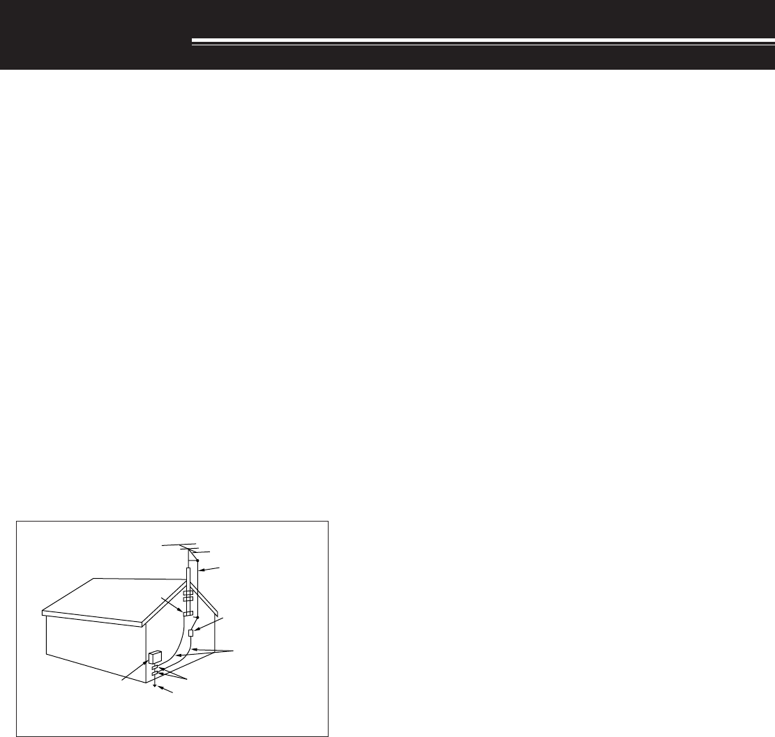
• Adequately ground all outdoor antennas for this
transceiver using approved methods. Grounding
helps protect against voltage surges caused by
lightning. It also reduces the chance of a build-up
of static charge.
EXAMPLE OF ANTENNA GROUNDING
ANTENNA
LEAD IN
WIRE
GROUND
CLAMP
ELECTRIC SERVICE
EQUIPMENT
ANTENNA
DISCHARGE UNIT
GROUNDING
CONDUCTORS
GROUND CLAMPS
POWER SERVICE
GROUNDING ELECTRODE
SYSTEM
• Minimum recommended distance for an outdoor
antenna from power lines is one and one-half
times the vertical height of the associated antenna
support structure. This distance allows adequate
clearance from the power lines if the support
structure fails for any reason.
• Locate the transceiver so as not to interfere with
its ventilation. Do not place books or other
equipment on the transceiver that may impede the
free movement of air. Allow a minimum of
4 inches (10 cm) between the rear of the
transceiver and the wall or operating desk shelf.
• Do not use the transceiver near water or sources
of moisture. For example, avoid use near a
bathtub, sink, swimming pool, or in a damp
basement or attic.
• The presence of an unusual odor or smoke is
often a sign of trouble. Immediately turn the
power OFF and remove the power cable. Contact
a KENWOOD service station or your dealer for
advice.
• Locate the transceiver away from heat sources
such as a radiator, stove, amplifier or other
devices that produce substantial amounts of heat.
• Do not use volatile solvents such as alcohol, paint
thinner, gasoline or benzene to clean the cabinet
of the transceiver. Use a clean cloth with warm
water or a mild detergent.
• Disconnect the input power cable from the power
source when the transceiver is not used for long
periods of time.
• Remove the transceiver’s enclosure only to do
accessory installations described in this manual or
accessory manuals. Follow provided instructions
carefully, to avoid electrical shocks. If unfamiliar
with this type of work, seek assistance from an
experienced individual, or have a professional
technician do the task.
• Enlist the services of qualified personnel in the
following cases:
a) The power supply or plug is damaged.
b) Objects have fallen or liquid has spilled into the
transceiver.
c) The transceiver has been exposed to rain.
d) The transceiver is operating abnormally or
performance has seriously degraded.
e) The transceiver has been dropped or the
enclosure damaged.

iv
CONTENTS
QUICK MENU ........................................................ 21
PROGRAMMING THE QUICK MENU ............... 21
USING THE QUICK MENU ............................... 21
MENU CONFIGURATION ..................................... 22
ALPHABETICAL FUNCTION LIST......................... 26
CHAPTER 7 BASIC COMMUNICATIONS
SSB TRANSMISSION ........................................... 28
FM TRANSMISSION ............................................. 28
AM TRANSMISSION ............................................. 29
NARROW BANDWIDTH FOR FM ......................... 29
NARROW BANDWIDTH FOR AM ......................... 29
CW TRANSMISSION ............................................ 30
AUTO ZERO-BEAT ........................................... 30
TX SIDETONE/ RX PITCH FREQUENCY ......... 30
CHAPTER 8 ENHANCED COMMUNICATIONS
SPLIT-FREQUENCY OPERATION ........................ 31
TF-SET (TRANSMIT FREQUENCY SET) .......... 31
FM REPEATER OPERATION ................................ 32
PROGRAMMING AN OFFSET .......................... 32
Selecting an Offset Direction ......................... 32
Selecting an Offset Frequency ...................... 32
TRANSMITTING A TONE .................................. 33
Activating the Tone Function ......................... 33
Selecting a Tone Frequency .......................... 33
Selecting Continuous or Burst ....................... 33
Transmitting a 1750 Hz Tone ........................ 33
AUTOMATIC REPEATER OFFSET ................... 34
REVERSE FUNCTION ...................................... 34
AUTOMATIC SIMPLEX CHECK (ASC) .............. 34
TONE FREQ. ID SCAN ..................................... 34
FM CTCSS OPERATION ....................................... 35
CTCSS FREQ. ID SCAN ................................... 35
FM DCS OPERATION ............................................. 36
DCS CODE ID SCAN ........................................ 36
CHAPTER 9 COMMUNICATING AIDS
RECEIVING ........................................................... 37
SELECTING YOUR FREQUENCY .................... 37
Direct Frequency Entry ................................. 37
Using 1 MHz Steps ....................................... 37
Quick QSY.................................................... 37
Fine Tuning................................................... 38
Equalizing VFO Frequencies (A=B) .............. 38
RIT (RECEIVE INCREMENTAL TUNING) .......... 38
AGC (AUTOMATIC GAIN CONTROL) ............... 38
TRANSMITTING .................................................... 39
VOX (VOICE-OPERATED TRANSMIT) ............. 39
Microphone Input Level................................. 39
Delay Time ................................................... 39
SPEECH PROCESSOR .................................... 40
XIT (TRANSMIT INCREMENTAL TUNING) ....... 40
CUSTOMIZING TRANSMIT SIGNAL
CHARACTERISTICS ......................................... 41
TX Filter Bandwidth (SSB/AM) ...................... 41
TX Equalizer (SSB/FM/AM) .......................... 41
TRANSMIT INHIBIT ........................................... 41
CHANGING FREQUENCY WHILE
TRANSMITTING................................................ 41
THANK YOU............................................................. i
FEATURES............................................................... i
SUPPLIED ACCESSORIES ..................................... i
WRITING CONVENTIONS FOLLOWED .................. i
MODELS COVERED BY THIS MANUAL ................. ii
MARKET CODES .................................................... ii
NOTICE TO USER .................................................. ii
PRECAUTIONS....................................................... iii
CONTENTS ............................................................ iv
CHAPTER 1 INSTALLATION
ANTENNA CONNECTION ....................................... 1
GROUND CONNECTION ........................................ 1
LIGHTNING PROTECTION ..................................... 1
DC POWER SUPPLY CONNECTION ...................... 2
UTILIZING THE BAIL (TS-2000 (X) ONLY) .............. 2
REPLACING FUSES ............................................... 2
ACCESSORY CONNECTIONS ............................... 3
FRONT PANEL .................................................... 3
Headphones (PHONES) ................................. 3
Microphone (MIC) ........................................... 3
REAR PANEL ...................................................... 3
External Speakers (EXT.SP1/ EXT.SP2) ......... 3
Keys for CW (PADDLE and KEY) ................... 3
CHAPTER 2 YOUR FIRST QSO (HF/ 50MHz band)
RECEIVING ............................................................. 4
TRANSMITTING ...................................................... 5
CHAPTER 3 YOUR FIRST QSO (VHF/ UHF band)
RECEIVING ............................................................. 6
TRANSMITTING ...................................................... 7
CHAPTER 4 GETTING ACQUAINTED
FRONT PANEL ........................................................ 8
REAR PANEL ........................................................ 13
DISPLAY ............................................................... 14
MICROPHONE ...................................................... 17
CHAPTER 5 OPERATING BASICS
SWITCHING POWER ON/OFF ............................. 18
ADJUSTING VOLUME .......................................... 18
AUDIO FREQUENCY (AF) GAIN....................... 18
RADIO FREQUENCY (RF) GAIN ...................... 18
SELECTING VFO A OR VFO B ............................. 18
SELECTING A BAND ............................................ 18
SELECTING A MODE ............................................ 19
ADJUSTING SQUELCH ........................................ 19
SELECTING A FREQUENCY ................................ 19
FRONT PANEL METER ......................................... 19
TRANSMITTING .................................................... 20
SELECTING TRANSMIT POWER ..................... 20
MICROPHONE GAIN ........................................ 20
CHAPTER 6 MENU SETUP
WHAT IS A MENU?................................................ 21
MENU A/ MENU B ................................................. 21
MENU ACCESS .................................................... 21

v
CONTENTS
RADIO TELETYPEWRITING (RTTY) .................... 51
AMTOR/PacTOR/CLOVER/G-TOR/PSK31 ........... 52
SLOW SCAN TV/ FACSIMILE ............................... 52
DX PACKET CLUSTER TUNE............................... 53
SATELLITE OPERATION ...................................... 53
BASIC OPERATION .......................................... 53
STORING SATELLITE MEMORY CHANNELS .. 54
RECALLING A SATELLITE MEMORY
CHANNEL ......................................................... 54
SATELLITE CHANNEL NAME ........................... 54
QUICK MEMORY IN SATELLITE MODE ........... 54
CHECKING THE UPLINK FREQUENCY........... 54
USING XIT/ RIT IN SATELLITE MODE .............. 54
CHANGING THE FREQUENCY BAND ............. 54
CHAPTER 12 REJECTING INTERFERENCE
DSP FILTERS ........................................................ 55
CHANGING THE RECEIVE FILTER
BANDWIDTH ..................................................... 55
SSB/ FM/ AM Modes .................................... 55
CW/ FSK Modes........................................... 55
NOTCH FILTER (SSB) ...................................... 56
BEAT CANCEL (SSB/ AM) ................................. 56
MANUAL BEAT CANCEL (ALL MODES) ........... 56
NOISE REDUCTION ......................................... 56
Setting the N.R. 1 Level Adjustment .............. 56
Settign the N.R. 2 Time Constant .................. 56
NOISE BLANKER .................................................. 57
PRE-AMPLIFIER ................................................... 57
ATTENUATOR ....................................................... 57
CHAPTER 13 MEMORY FEATURES
MEMORY CHANNELS .......................................... 58
STORING DATA IN MEMORY ........................... 58
Simplex Channels ......................................... 58
Split-Frequency Channels ............................. 59
MEMORY RECALL AND SCROLL .................... 59
Memory Recall.............................................. 59
Memory Scroll............................................... 60
Temporary Frequency Changes .................... 60
MEMORY-VFO SPLIT OPERATION .................. 60
MEMORY TRANSFER ...................................... 61
Memory ➡ VFO Transfer .............................. 61
Channel ➡ Channel Transfer ........................ 61
STORING FREQUENCY RANGES ................... 62
Confirming Start/End Frequencies ................ 62
Programmable VFO...................................... 62
Memory Channel Lockout ............................. 62
ERASING MEMORY CHANNELS ..................... 62
MEMORY CHANNEL NAME ............................. 63
MEMORY GROUP ............................................ 64
Memory Group Select ................................... 64
QUICK MEMORY .................................................. 64
STORING INTO QUICK MEMORY .................... 64
RECALLING QUICK MEMORY CHANNELS ..... 65
TEMPORARY FREQUENCY CHANGES .......... 65
QUICK MEMORY ➡ VFO TRANSFER .............. 65
CW BREAK-IN....................................................... 42
USING SEMI BREAK-IN OR
FULL BREAK-IN ................................................ 42
ELECTRONIC KEYER .......................................... 42
CHANGING KEYING SPEED ............................ 42
AUTO WEIGHTING ........................................... 42
Reverse Keying Weight Ratio ....................... 42
BUG KEY FUNCTION ....................................... 43
CW MESSAGE MEMORY ................................. 43
Storing CW Messages .................................. 43
Checking CW Messages without
Transmitting .................................................. 43
Transmitting CW Messages .......................... 43
Changing the Inter-message Interval Time .... 44
Changing the Sidetone Volume ..................... 44
Inset Keying .................................................. 44
FREQUENCY CORRECTION FOR CW ............ 44
CW REVERSE (RECEIVE)................................ 44
AUTO CW TX IN SSB MODE ............................ 44
CHAPTER 10 SUB-RECEIVER
SUB-RECEIVER .................................................... 45
TX BAND AND CONTROL BAND .......................... 45
TX BAND ........................................................... 45
CONTROL BAND .............................................. 45
RECEIVING ........................................................... 45
ACTIVATING THE SUB-RECEIVER .................. 45
CONTROLLING THE SUB-RECEIVER ............. 45
SELECTING A BAND ........................................ 45
ADJUSTING THE AUDIO FREQUENCY (AF)
GAIN ................................................................. 46
ADJUSTING THE SQUELCH ............................ 46
SELECTING A FREQUENCY ............................ 46
SUB-RECEIVER PANEL METER ...................... 46
SELECTING A MODE FOR
THE SUB-RECEIVER........................................ 46
FM CTCSS OPERATION................................... 46
FM DCS OPERATION ....................................... 46
TONE FREQ. ID SCAN ..................................... 46
DCS CODE ID SCAN ........................................ 46
ATTENUATOR................................................... 47
PRE-AMPLIFIER ............................................... 47
DUAL WATCH ................................................... 47
SCAN ................................................................ 47
NOISE REDUCTION ......................................... 47
TRANSMITTING .................................................... 47
SELECTING A TRANSMIT POWER .................. 47
MICROPHONE GAIN ........................................ 47
FM REPEATER OPERATION ............................ 47
REVERSE FUNCTION ...................................... 47
AUTOMATIC SIMPLEX CHECK (ASC) .............. 48
TRANSMITTING A TONE .................................. 48
MEMORY .............................................................. 48
CHAPTER 11 SPECIALIZED COMMUNICATIONS
PACKET RADIO .................................................... 49
BUILT-IN TNC ........................................................ 49
PREPARATION ..................................................... 50
DCD SENSE.......................................................... 50

vi
CONTENTS
TNC ....................................................................... 79
TRANSVERTER .................................................... 79
TX MONITOR ........................................................ 79
TX POWER ........................................................... 79
QUICK DATA TRANSFER ..................................... 80
SETTING UP ..................................................... 80
Equipment Needed ....................................... 80
Connections ................................................. 80
USING QUICK TRANSFER ............................... 80
Transferring Data .......................................... 80
Receiving Data ............................................. 80
COMPUTER CONTROL........................................ 81
SETTING UP ..................................................... 81
Equipment Needed ....................................... 81
Connections ................................................. 81
COMMUNICATION PARAMETERS ....................... 81
REMOTE MICROPHONE CONTROLLER ............. 81
WIRELESS REMOTE CONTROL (K-type ONLY) .. 82
PREPARATION ................................................. 82
CONTROL OPERATION ................................... 82
SKY COMMAND II+ (K-type ONLY) ....................... 83
PREPARATION ................................................. 83
CONTROL OPERATION ................................... 84
USING TH-D7A AS A COMMANDER ................. 85
CONTROL OPERATION ................................... 85
USING ANOTHER TS-2000
AS A COMMANDER .......................................... 87
USING A SEPARATE TRANSPORTER ............. 88
REPEATER FUNCTION (K-type ONLY)................. 88
LOCK-BAND REPEATER .................................. 88
CROSS-BAND REPEATER ............................... 88
HANG TIME FOR REPEATER FUNCTION ....... 88
DRU-3A DIGITAL RECORDING UNIT
(OPTIONAL) .......................................................... 89
RECORDING MESSAGES ................................ 89
MESSAGE PLAYBACK ..................................... 89
Checking Messages ..................................... 89
Sending Messages ....................................... 90
Erasing a Recorded Message ....................... 90
Changing Inter-message Interval Time .......... 90
Changing Playback Volume .......................... 90
VS-3 VOICE SYNTHESIZER (OPTIONAL) ............ 91
MICROPROCESSOR RESET ............................... 92
INITIAL SETTINGS ............................................ 92
PARTIAL RESET ............................................... 92
FULL RESET ..................................................... 92
CHAPTER 16 CONNECTING PERIPHERAL EQUIPMENT
COMPUTER .......................................................... 93
COMPATIBLE TRANSCEIVER .............................. 93
RTTY EQUIPMENT ............................................... 94
HF LINEAR AMPLIFIER ........................................ 94
ANTENNA TUNER ................................................ 94
MCP AND TNC ...................................................... 95
TYPICAL MCP/ TNC SETUP ................................. 96
LINEAR AMPLIFIER (50 MHz, 144 MHz, 430
(440) MHz and 1.2 GHz) ........................................ 96
CHAPTER 14 SCAN
NORMAL SCAN .................................................... 66
VFO SCAN ........................................................ 66
PROGRAM SCAN ............................................. 67
PROGRAM SCAN PARTIALLY SLOWED.......... 67
SCAN HOLD ..................................................... 68
MHz SCAN ........................................................ 68
MEMORY SCAN.................................................... 68
SCAN RESUME METHOD ................................ 68
ALL-CHANNEL SCAN ....................................... 68
GROUP SCAN .................................................. 69
CALL SCAN....................................................... 69
VISUAL SCAN ................................................... 70
Using Visual Scan (VFO) .............................. 70
Changing the Number of Channels to Scan .. 70
Using Visual Scan (Memory Channel) ........... 70
CHAPTER 15 OPERATOR CONVENIENCES
ALT (Auto Lock Tuning) .......................................... 72
ANTENNAS ........................................................... 72
HF/ 50 MHz BAND............................................. 72
VHF/ UHF/ 1.2 GHZ BAND ................................ 72
APO (Auto Power OFF) ......................................... 72
AUTOMATIC ANTENNA TUNER ........................... 72
Presetting .......................................................... 73
ATTENUATOR ....................................................... 73
AUTO MODE ......................................................... 73
BEEP FUNCTION.................................................. 74
CALL CHANNEL .................................................... 75
DISPLAY ............................................................... 75
BRIGHTNESS ................................................... 75
CONTRAST....................................................... 75
KEY ILLUMINATION .......................................... 75
DTMF .................................................................... 75
MANUAL DTMF DIALING .................................. 75
DTMF MEMORY ............................................... 75
Entering DTMF tones .................................... 75
Transmitting DTMF Memory Channel Data ... 76
DTMF Tone Time Length .............................. 76
DTMF Pause Period ..................................... 76
HF RX ANTENNA .................................................. 76
LINEAR AMPLIFIER CONTROL ............................ 76
LOCK FUNCTIONS ............................................... 77
FREQUENCY LOCK FUNCTION ...................... 77
LOCK ALL FUNCTION ...................................... 77
MICROPHONE PF KEYS ...................................... 77
MONITOR ............................................................. 77
PF KEY.................................................................. 77
RISE TIME OF CW ................................................ 77
RX DSP EQUALIZER ............................................ 78
EQUALIZING RECEIVING AUDIO
(SSB/ FM/ AM) ................................................... 78
SEPARATE SPEAKER OUTPUT ........................... 78
S-METER SQUELCH ............................................ 78
SQUELCH HANG TIME..................................... 78
TIME-OUT TIMER ................................................. 78

vii
CONTENTS
CHAPTER 17 INSTALLING OPTIONS
REMOVING THE BOTTOM CASE ........................ 97
DRU-3A DIGITAL RECORDING UNIT ................... 97
VS-3 VOICE SYNTHESIZER UNIT........................ 97
MB-430 MOBILE BRACKET .................................. 98
RC-2000 REMOTE PANEL .................................... 98
CHAPTER 18 TROUBLESHOOTING
GENERAL INFORMATION .................................... 99
SERVICE........................................................... 99
SERVICE NOTE ................................................ 99
CLEANING ........................................................ 99
LITHIUM BATTERY ............................................... 99
DEMONSTRATION MODE .................................... 99
TROUBLESHOOTING ......................................... 100
OPERATION NOTICES ....................................... 103
DC POWER SUPPLY ...................................... 103
TX SIGNAL HARMONICS ............................... 103
INTERNAL BEATS .......................................... 103
VISUAL SCAN ................................................. 103
SENSITIVITY (K-type ONLY) ........................... 103
AGC ................................................................ 103
SUB-RECEIVER.............................................. 103
CHAPTER 19 OPTIONAL ACCESSORIES
OPTIONAL ACCESSORIES ................................ 104
CHAPTER 20 SPECIFICATIONS
SPECIFICATIONS ............................................... 105
CHAPTER 21 APPENDIX
TS-B2000 FRONT PANEL ................................... 109
BUILT-IN TNC COMMAND LIST .......................... 110
COM CONNECTOR ............................................ 113
HARDWARE DESCRIPTION ........................... 113
CONTROL OPERATION ................................. 113
COMPUTER CONTROL.................................. 114
Alphabetical Commands ............................. 114
Parameters ................................................. 114
Terminator .................................................. 114
Error Messages .......................................... 114
PC CONTROL COMMAND TABLES ................... 115
CHAPTER 22 INDEX
INDEX ................................................................. 142
1
INSTALLATION
ANTENNA CONNECTION
An antenna system consists of an antenna, feed line,
and ground. The transceiver can give excellent
results if the antenna system and its installation are
given careful attention. Use a properly adjusted 50Ω
antenna of good quality, a high-quality 50Ω coaxial
cable, and first-quality connectors. All connections
must be clean and tight.
After making the connections, match the impedance
of the coaxial cable and antenna so that the SWR is
1.5:1 or less. High SWR will cause the transmit
output to drop and may lead to radio frequency
interference to consumer products such as stereo
receivers and televisions. You may even interfere
with your own transceiver. Reports that your signal is
distorted could indicate that your antenna system is
not efficiently radiating the transceiver’s power.
Connect your primary HF/ 50 MHz antenna feed line
to ANT 1 on the rear of the transceiver. If you are
using two HF/ 50 MHz antennas, connect the
secondary antenna to ANT 2. Connect VHF
(144 MHz), UHF (430/ 440 MHz), and 1.2 GHz
(TS-2000/ TS-B2000 Optional) antennas to their
respective antenna connectors on the rear of the
transceiver. Refer to page 13 for the location of the
antenna connectors.
◆
Transmitting without connecting an antenna or other
matched load may damage the transceiver. Always
connect the antenna to the transceiver before transmitting.
◆
All fixed stations should be equipped with a lightning
arrester to reduce the risk of fire, electric shock, and
transceiver damage.
Note: The transceiver’s protection circuit will activate when the SWR
is greater than 2.5:1; however, do not rely on protection to
compensate for a poorly functioning antenna system.
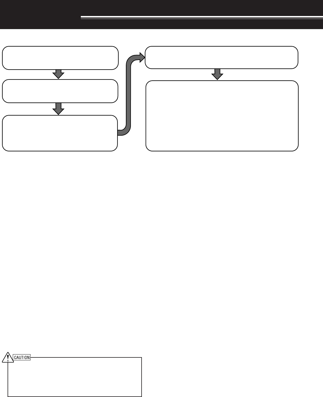
Connect all accessories to the transceiver {pages 3, 94}.
Accessories include the following:
• Microphone
• Antenna Tuner
• CW Key
• Computer
• TNC/ Multimode
Communications Processor
Install and connect an antenna system
{page 1}.
Install a ground system that satisfies DC
and RF grounding requirements {page 1}.
Install lightning protection to protect the
antenna system, your personal safety,
and your property {page 1}.
Install and connect a DC power supply {page 2}.
• Headphones
• External Speaker
• RTTY Equipment
• Linear Amplifier
• Remote Panel
GROUND CONNECTION
At the minimum, a good DC ground is required to
prevent such dangers as electric shock. For superior
communications results, a good RF ground is
required, against which the antenna system can
operate. Both of these conditions can be met by
providing a good earth ground for your station. Bury
one or more ground rods or a large copper plate
under the ground, then connect this to the transceiver
GND terminal. Use heavy gauge wire or a copper
strap, cut as short as possible, for this connection.
Do not use a gas pipe, an electrical conduit, or a
plastic water pipe as a ground.
LIGHTNING PROTECTION
Even in areas where lightning storms are less
common, there are usually a limited number of
storms each year. Consider carefully how to protect
your equipment and home from lightning. The
installation of a lightning arrestor is a start, but there
is more that you can do. For example, terminate your
antenna system transmission lines at an entry panel
that you install outside your home. Ground this entry
panel to a good outside ground, then connect the
appropriate feed lines between the entry panel and
your transceiver. When a lightning storm occurs,
disconnecting the feed lines from your transceiver will
ensure added protection.
2
1 INSTALLATION
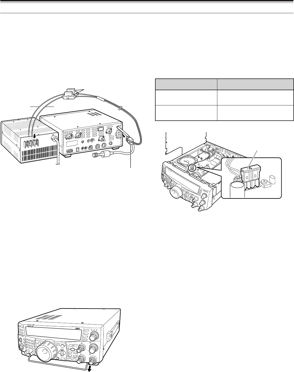
DC POWER SUPPLY CONNECTION
In order to use this transceiver, you need a separate
13.8 V DC power supply that must be purchased
separately. Do not directly connect the transceiver to
an AC outlet. Use the supplied DC power cable to
connect the transceiver to a regulated power supply.
Do not substitute a cable with smaller gauge wires.
The current capacity of the power supply must be
20.5 A peak or more.
TS-2000/ TS-2000X
TS-B2000
First, connect the DC power cable to the regulated
DC power supply; the red lead to the positive terminal
and the black lead to the negative terminal. Next,
connect the DC power cable to the transceiver’s DC
power connector. Press the connectors firmly
together until the locking tab clicks.
Note:
◆
Before connecting the DC power supply to the transceiver, be
sure to switch OFF the DC power supply and transceiver.
◆
Do not plug the DC power supply into an AC outlet until you
make all connections.
UTILIZING THE BAIL (TS-2000(X) ONLY)
This transceiver is equipped with a bail so that you
can angle the transceiver. The bail is located on the
bottom of the transceiver. Pull the bail forward to the
limit as shown.
REPLACING FUSES
If a fuse blows, determine the cause then correct the
problem. Only after the problem has been resolved,
replace the blown fuse with a new one with the
specified ratings. If newly installed fuses continue to
blow, disconnect the power plug and contact a
KENWOOD service station or your dealer for
assistance.
noitacoLesuF gnitaRtnerruCesuF
/)X(0002-ST 0002B-ST A4
)renutannetnalanretxenaroF(
rewopCDdeilppuS elbac A52
Fuse holders
(Fuse 25 A)
DC 13.8 V
RedBlack
Pull the bail
Fuse (4 A)
3
1 INSTALLATION
ACCESSORY CONNECTIONS
FRONT PANEL
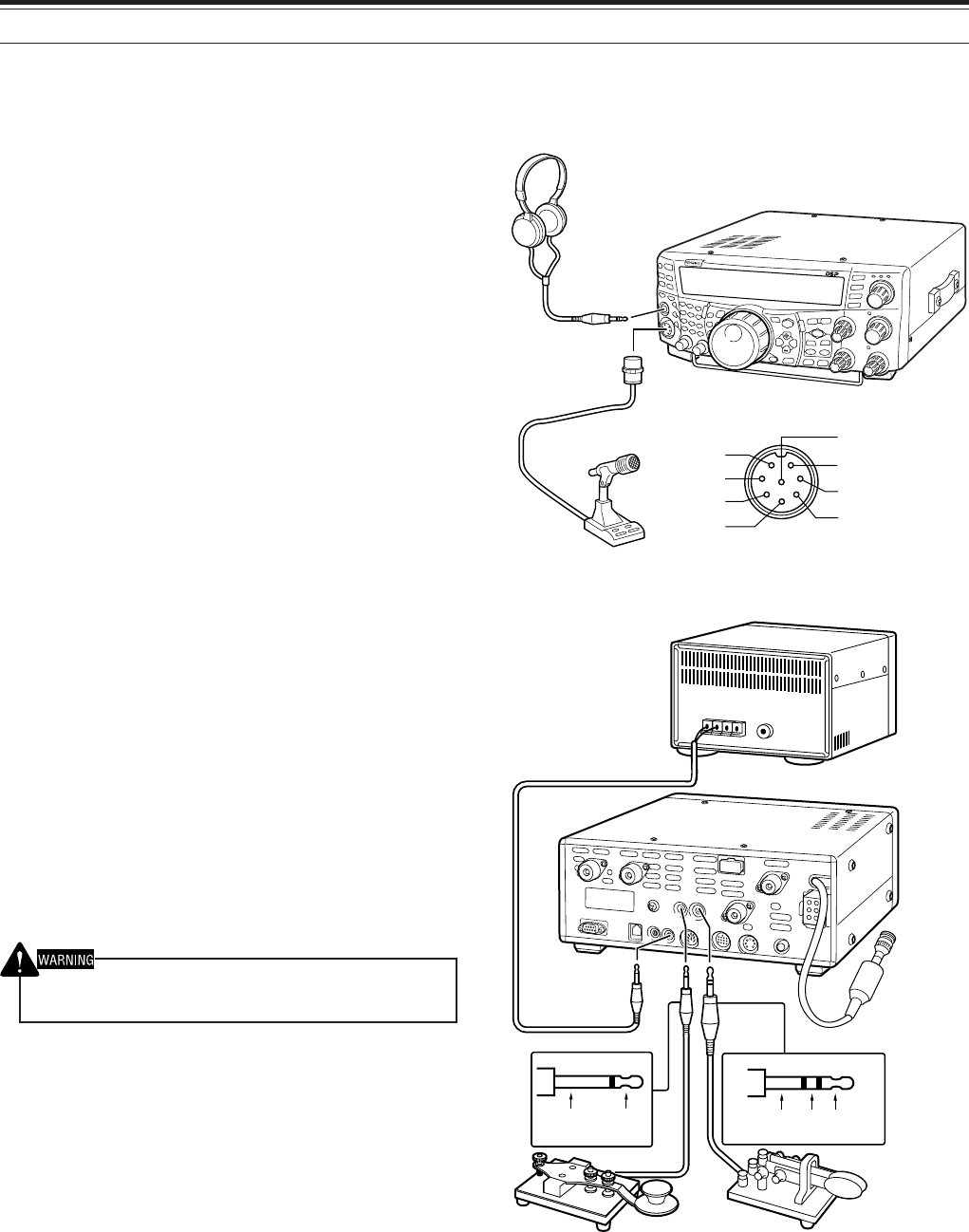
■Headphones (PHONES)
Connect monaural or stereo headphones having a
4 to 32Ω impedance. This jack accepts a
6.3 mm (1/4") diameter, 2-conductor (mono) or
3-conductor (stereo) plug. After connecting the
headphones, you will hear no sound from the
internal (or optional external) speaker.
■Microphone (MIC)
Connect a microphone having an impedance
between 250 and 600Ω. Fully insert the
connector, then screw the retaining ring clockwise
until secure. Compatible microphones include the
MC-43S, MC-47, MC-52DM, MC-60A, MC-80,
MC-85, and MC-90. Do not use the MC-44,
MC-44DM, MC-45, MC-45E, MC-45DM,
MC-45DME, or MC-53DM microphones.
REAR PANEL
■External Speakers (EXT.SP1/ EXT.SP2)
This transceiver has 2 independent receivers.
Thus, it can output 2 separate audio signals. As a
default, the transceiver mixes both audio signals
internally and outputs them from the internal
speaker. On the rear panel of the transceiver,
there are 2 external speaker jacks. If an external
speaker is connected to EXP.SP1, the internal
speaker will mute. If the speaker is connected to
EXT.SP2, both the external speaker and the
internal speaker will function. Use only external
speakers with an impedance of 4 to 8Ω (8Ω
nominal). These jacks accept only 3.5 mm (1/8")
diameter, 2-conductor (mono) plugs.
Do not connect headphones to this jack. The high audio output
of this jack could damage your hearing.
■Keys for CW (PADDLE and KEY)
For CW operation using the internal electronic
keyer, connect a keyer paddle to the PADDLE
jack. For CW operation without using the internal
electronic keyer, connect a straight key,
semi-automatic key (bug), electronic keyer, or the
CW keyed output from a Multimode
Communications Processor (MCP) to the KEY
jack. The PADDLE and KEY jacks mate with a
6.3 mm (1/4") 3-conductor plug and a 3.5 mm
(1/8") 2-conductor plug respectively. External
electronic keyers or MCPs must use positive
keying to be compatible with this transceiver. Use
a shielded cable between the key and the
transceiver.
Note: Due to the functionality of the internal electronic keyer, you
may find it unnecessary to connect both a paddle and another
type of keyer unless you want to use a PC-based keyer for CW.
Read the “ELECTRONIC KEYER” section {page 42} to become
familiar with the internal keyer.
i
qu
y
t
w
e
r
TS-2000
TS-2000X
TS-B2000
+
• Straight key • Paddle
• Bug key
• Electronic keyer
• MCP CW output
GND GND dash dot
Microphone
Headphone
TS-2000
TS-2000X
TS-B2000
MIC connector (Front view)
GND (STBY)
GND (MIC)
NC
8 V (10 mA max)
MIC
PTT
DOWN
UP
External speaker
4
YOUR FIRST QSO (HF/ 50 MHz band)
Are you ready to give your TS-2000(X) a quick try? Reading these two pages should get your voice on the air
in your first QSO on the HF/ 50 MHz band shortly. The instructions below are intended only for a quick guide.
If you encounter problems or there is something you don’t understand, read the detailed explanations given
later in this manual.
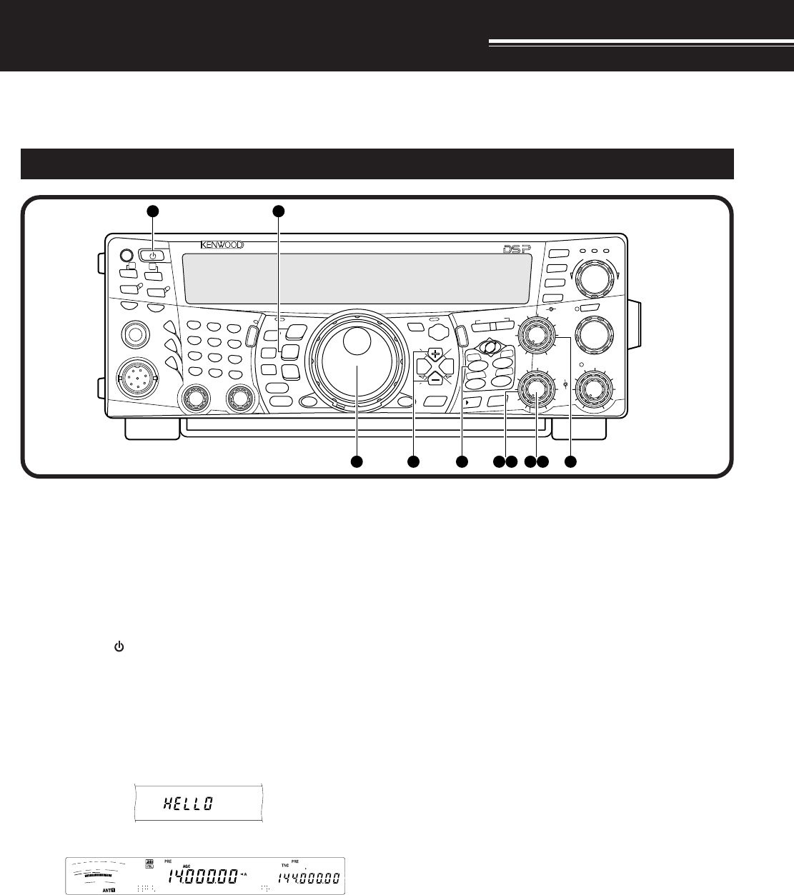
RECEIVING
PF
F LOCK A
1
CH1/REC
2
CH2/REC
3
CH3/REC
4
TONE/SEL
5
METER
6
CTCSS/SEL
7
NB/LEVEL
8
AGC/OFF
9
FINE/STEP
.
DCS/SEL
0
SHIFT/OFFSET
ENT
SEND
PHONES
MIC
AT
ANT1/2
PROC
LEVEL
VOX
ATT PRE
LEVEL
LEVEL
LEVEL
MANUAL
LO/
WIDTH
HI/
SHIFT
N.R.
A.N.
B.C.
FUNC
CALL
C.IN
CLR
MAIN
AUTO
CAR
TX MONI
DELAY NAR
REV
MIC
PWR
KEY
LSB
USB
CW
FSK
FM
AM
SUB
DISP
SEL
1MHz CTRL
MR
MG.SEL
M.IN
QUICK MEMO
M/S REV
TRACE
MAIN
MANUAL
RF
AF
SQL
SUB
CH
MULTI
BC MAIN
GAIN
VFO/CH
MENU TF-
SET
MAIN SUB
SG.SEL
SCAN M VFO M.IN
RIT
CW TUNE 9.6k STA
RIT/SUB
CON
XIT
ALT
SET
CLEAR
P.C .T
_+
HF/VHF/UHF ALL MODE MULTI BANDER TS-2000
SATL
A/B
VFO/M
SPLIT
A=B
62
18 5 3 1 7 1 4
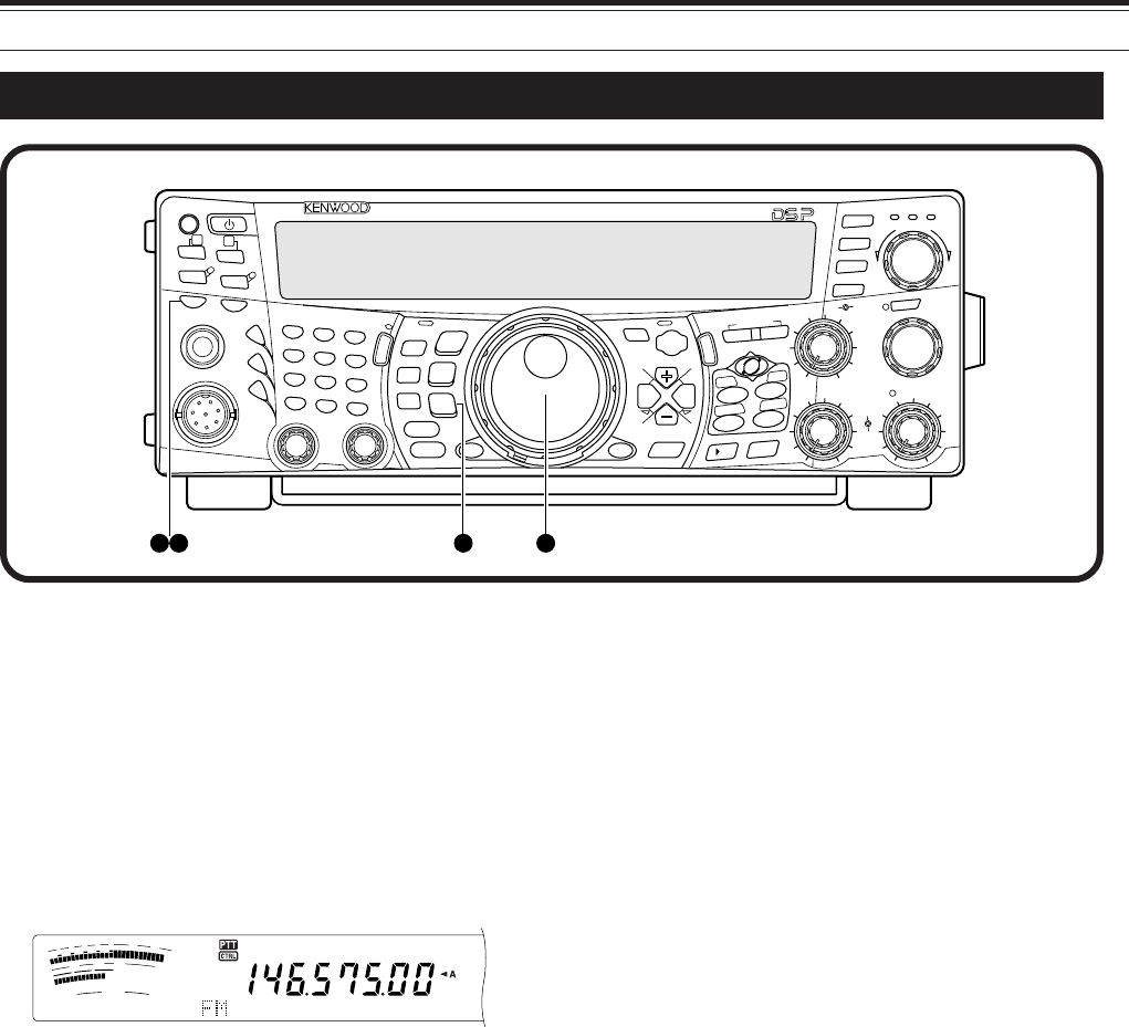
Note: This section explains only keys and controls required to
briefly try the transceiver.
qSet the following as specified:
•MAIN AF: Fully counterclockwise
•MAIN RF GAIN: Fully clockwise
•MAIN SQL: Fully counterclockwise
wSwitch ON the DC power supply, then press
and hold [ ] (POWER) briefly on the
transceiver.
• Do not press the switch for more than
approximately 2 seconds; the transceiver
will be switched OFF.
• Upon power up, “HELLO” appears, followed
by the selected frequency and other
indicators.
d
F
I
L
T
E
R
S
1
3
5
7
9
2
0
4
0
6
0
d
B
P
W
R
1
0
2
5
5
0
1
0
0
W
A
L
C
eConfirm that VFO A has been selected for
communications; “tA” should be visible on
the display. If it has not, press [A/B] to select
VFO A.
rTurn the MAIN AF control slowly clockwise
until you hear a suitable level of background
noise.
tPress [+]/ [–] to select an HF/ 50 MHz Amateur
radio band.
yPress [LSB/ USB/ AUTO] or [FM/ AM/ NAR] to
select an operating mode.
• To select the second mode on each key,
press the same key again. For example,
each press of [LSB/ USB/ AUTO] switches
between LSB and USB modes.
uIf you have selected FM, turn the MAIN SQL
control clockwise until the background noise is
just eliminated; the MAIN band LED (above the
[MIC/ CAR] key) turns off.
• With LSB or USB selected, skip this step.
iTurn the Tuning control to tune in a station.
• If you do not hear any stations, you may
have the wrong antenna connector selected.
Press [FUNC], [AT/ ANT1/2] to switch
between the antenna 1 and 2 connectors.
5
2 YOUR FIRST QSO (HF/ 50 MHz band)
TRANSMITTING
PF
F LOCK A
1
CH1/REC
2
CH2/REC
3
CH3/REC
4
TONE/SEL
5
METER
6
CTCSS/SEL
7
NB/LEVEL
8
AGC/OFF
9
FINE/STEP
.
DCS/SEL
0
SHIFT/OFFSET
ENT
SEND
PHONES
MIC
AT
ANT1/2
PROC
LEVEL
VOX
ATT PRE
LEVEL
LEVEL
LEVEL
MANUAL
LO/
WIDTH
HI/
SHIFT
N.R.
A.N.
B.C.
FUNC
CALL
C.IN
CLR
MAIN
AUTO
CAR
TX MONI
DELAY NAR
REV
MIC
PWR
KEY
LSB
USB
CW
FSK
FM
AM
SUB
DISP
SEL
1MHz CTRL
MR
MG.SEL
M.IN
QUICK MEMO
M/S REV
TRACE
MAIN
MANUAL
RF
AF
SQL
SUB
CH
MULTI
BCMAIN
GAIN
VFO/CH
MENU TF-
SET
MAIN SUB
SG.SEL
SCAN M VFO M.IN
RIT
CW TUNE 9.6k STA
RIT/SUB
CON
XIT
ALT
SET
CLEAR
P.C .T
_+
HF/VHF/UHF ALL MODE MULTI BANDER TS-2000
SATL
A/B
VFO/M
SPLIT
A=B
4 9
71
85
32
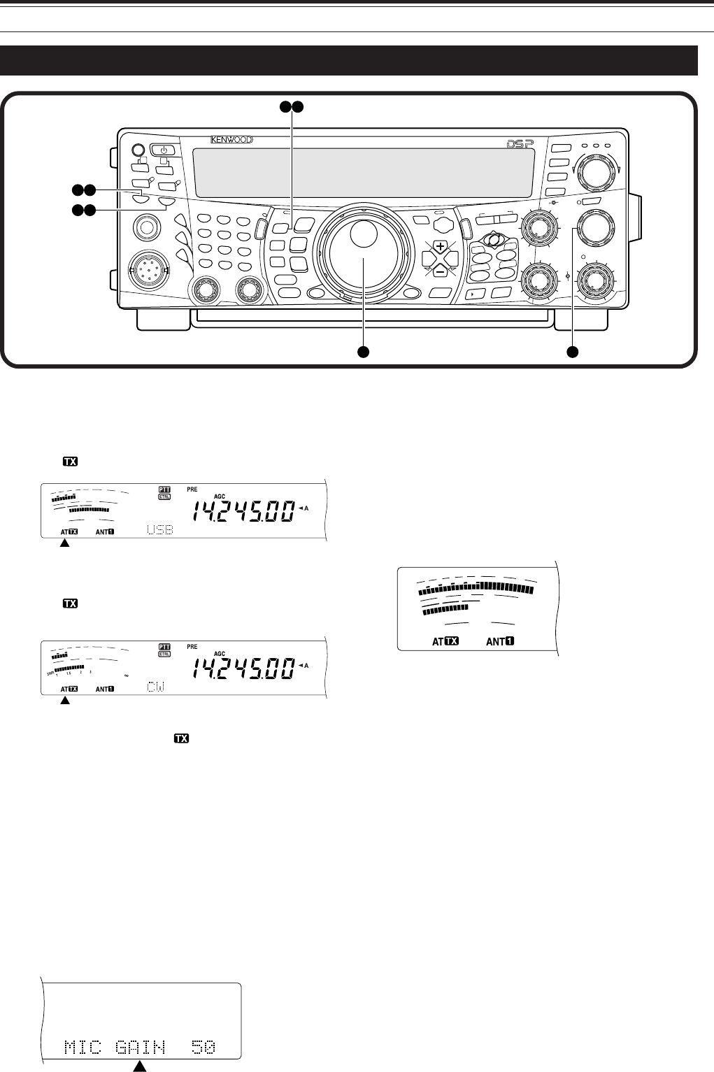
qTurn the Tuning control to tune in a desired
station or to select an unused frequency.
wPress [AT/ ANT1/2] momentarily.
•“AT” appears.
F
I
L
T
E
R
S
1
3
5
7
9
2
0
4
0
6
0
d
B
P
W
R
1
0
2
5
5
0
1
0
0
W
A
L
C
ePress and hold [AT/ ANT1/2] to activate the built-
in antenna tuner.
•“AT” starts blinking and the MAIN band LED
above the [MIC/ CAR] key turns red.
F
I
L
T
E
R
S
1
3
5
7
9
2
0
4
0
6
0
d
B
P
W
R
1
0
2
5
5
0
1
0
0
W
A
L
C
• Tuning should be completed in under
20 seconds, then “AT ” stops blinking.
• If tuning is not completed within 20 seconds,
error beeps sound. Press [AT/ ANT1/2] to stop
the error beeps and quit tuning. Check your
antenna system before continuing. If you do
not press [AT/ ANT1/2], tuning will continue for
approximately 60 seconds.
Note: You will hear a lot of clicking sounds coming from the
transceiver while the antenna tuner is trying to tune the antenna.
This is simply the relay switches turning ON and OFF.
rWith LSB, USB, or AM selected, press
[MIC/ CAR] to activate the Microphone Gain
Adjust.
• “MIC GAIN 50” appears.
• With FM selected, skip this step.
tPress [SEND].
• The MAIN band LED turns red.
yBegin speaking into the microphone in your
normal tone of voice.
uLSB/ USB: While speaking into the microphone,
adjust the MULTI/ CH control so that the ALC
meter reflects according to your voice level.
P
W
R
1
0
2
5
5
0
1
0
0
W
F
I
L
T
E
R
S
1
3
5
7
9
2
0
4
0
6
0
d
B
A
L
C
AM: While speaking into the microphone, adjust
the MULTI/ CH control so that the calibrated
power meter slightly reflects to your voice level.
FM: Skip this step.
iWhen you finish speaking, press [SEND] to return
to receive mode.
oPress [MIC/ CAR] to quit the Microphone Gain
Adjustment.
Note: If desired, access Menu No. 41 {page 28} to try the
Microphone Gain Adjust for FM.
This completes your introduction to the
TS-2000(X), but there is a great deal more to know.
“OPERATING BASICS” {page 18} and the following
chapters explain all the functions of this transceiver,
starting with the most basic, commonly-used
functions.
6
YOUR FIRST QSO (VHF/ UHF band)
If your primary operating band is VHF (144 MHz) or UHF (430/ 440 MHz), the TS-2000(X) can also serve you
as a powerful All-mode VHF/ UHF transceiver. The instructions below are intended only for a quick guide to
get you up on the air on the VHF/ UHF band. If you encounter problems or there is something you don’t
understand, read the detailed explanations given later in this manual.
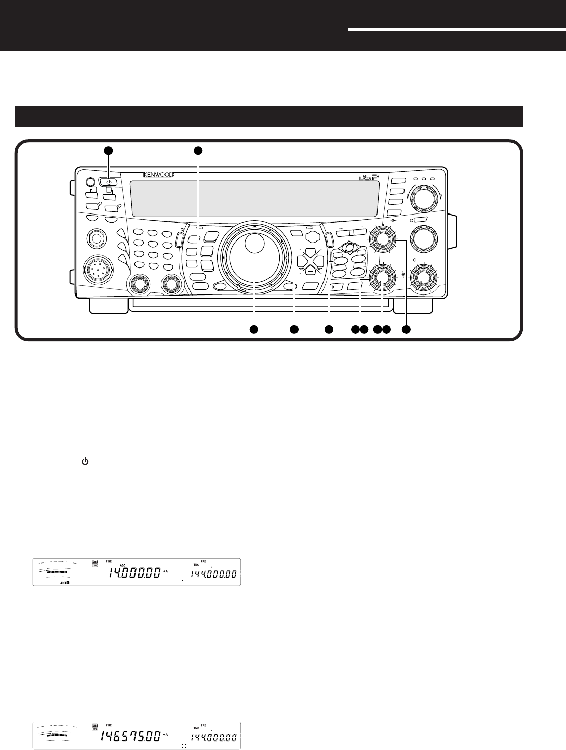
RECEIVING
PF
F LOCK A
1
CH1/REC
2
CH2/REC
3
CH3/REC
4
TONE/SEL
5
METER
6
CTCSS/SEL
7
NB/LEVEL
8
AGC/OFF
9
FINE/STEP
.
DCS/SEL
0
SHIFT/OFFSET
ENT
SEND
PHONES
MIC
AT
ANT1/2
PROC
LEVEL
VOX
ATT PRE
LEVEL
LEVEL
LEVEL
MANUAL
LO/
WIDTH
HI/
SHIFT
N.R.
A.N.
B.C.
FUNC
CALL
C.IN
CLR
MAIN
AUTO
CAR
TX MONI
DELAY NAR
REV
MIC
PWR
KEY
LSB
USB
CW
FSK
FM
AM
SUB
DISP
SEL
1MHz CTRL
MR
MG.SEL
M.IN
QUICK MEMO
M/S REV
TRACE
MAIN
MANUAL
RF
AF
SQL
SUB
CH
MULTI
BC MAIN
GAIN
VFO/CH
MENU TF-
SET
MAIN SUB
SG.SEL
SCAN M VFO M.IN
RIT
CW TUNE 9.6k STA
RIT/SUB
CON
XIT
ALT
SET
CLEAR
P.C .T
_+
HF/VHF/UHF ALL MODE MULTI BANDER TS-2000
SATL
A/B
VFO/M
SPLIT
A=B
62
18 5 3 1 7 1 4
Note: This section explains only keys and controls required to
briefly try the transceiver.
qSet the following as specified:
•MAIN AF: Fully counterclockwise
•MAIN RF GAIN: Fully clockwise
•MAIN SQL: Fully counterclockwise
wSwitch ON the DC power supply, then press
and hold [ ] (POWER) briefly on the
transceiver.
• Do not press the switch for more than
approximately 2 seconds; the transceiver
will be switched OFF.
• Upon power up, “HELLO” appears, followed
by the selected frequency and other
indicators.
F
I
L
T
E
R
S
1
3
5
7
9
2
0
4
0
6
0
d
B
P
W
R
1
0
2
5
5
0
1
0
0
W
A
L
C
ePress [MAIN], then confirm that VFO A has
been selected for communications; “tA”
should be visible on the display. If it has not,
press [A/B] to select VFO A.
rTurn the MAIN AF control slowly clockwise
until you hear a suitable level of background
noise.
tPress [+]/ [–] to move up to the VHF
(144 MHz) or UHF (430/ 440 MHz) Amateur
radio band.
F
I
L
T
E
R
S
1
3
5
7
9
2
0
4
0
6
0
d
B
P
W
R
1
0
2
5
5
0
1
0
0
W
A
L
C
yConfirm that the operating mode is FM. If it is
not, press [FM/ AM/ NAR] to select FM.
uTurn the SQL control clockwise until the
background noise is just eliminated; the MAIN
band LED turns off.
iTurn the Tuning control to tune in a station.
• You can use the MULTI/ CH control to
change the frequency faster. If you do not
hear any stations, the antenna may not be
installed or connected properly. Check
the antenna connector on the rear panel
{page 13}.
7
3 YOUR FIRST QSO (VHF/ UHF band)
TRANSMITTING
PF
F LOCK A
1
CH1/REC
2
CH2/REC
3
CH3/REC
4
TONE/SEL
5
METER
6
CTCSS/SEL
7
NB/LEVEL
8
AGC/OFF
9
FINE/STEP
.
DCS/SEL
0
SHIFT/OFFSET
ENT
SEND
PHONES
MIC
AT
ANT1/2
PROC
LEVEL
VOX
ATT PRE
LEVEL
LEVEL
LEVEL
MANUAL
LO/
WIDTH
HI/
SHIFT
N.R.
A.N.
B.C.
FUNC
CALL
C.IN
CLR
MAIN
AUTO
CAR
TX MONI
DELAY NAR
REV
MIC
PWR
KEY
LSB
USB
CW
FSK
FM
AM
SUB
DISP
SEL
1MHz CTRL
MR
MG.SEL
M.IN
QUICK MEMO
M/S REV
TRACE
MAIN
MANUAL
RF
AF
SQL
SUB
CH
MULTI
BC MAIN
GAIN
VFO/CH
MENU TF-
SET
MAIN SUB
SG.SEL
SCAN M VFO M.IN
RIT
CW TUNE 9.6k STA
RIT/SUB
CON
XIT
ALT
SET
CLEAR
P.C.T
_+
HF/VHF/UHF ALL MODE MULTI BANDER TS-2000
SATL
A/B
VFO/M
SPLIT
A=B
1 23 5
qConfirm that the operating mode is FM. If it is not,
press [FM/ AM/ NAR] to change the operating
mode to FM.
wTurn the Tuning control or the MULTI/ CH control
to tune in a desired station or to select an unused
frequency.
ePress [SEND].
• The MAIN band LED turns red.
rBegin speaking into the microphone in your
normal tone of voice.
F
I
L
T
E
R
S
1
3
5
7
9
2
0
4
0
6
0
d
B
P
W
R
1
0
2
5
5
0
1
0
0
W
A
L
C
tWhen you finish speaking, press [SEND] to return
to receive mode.
This completes your introduction on how to receive
and transmit using the TS-2000(X) on a VHF/ UHF
band. Refer to “OPERATING BASICS” {page 18} and
the following chapters for explanations on all the
functions of this transceiver.
8
GETTING ACQUAINTED
FRONT PANEL
PF
F LOCK A
1
CH1/REC
2
CH2/REC
3
CH3/REC
4
TONE/SEL
5
METER
6
CTCSS/SEL
7
NB/LEVEL
8
AGC/OFF
9
FINE/STEP
.
DCS/SEL
0
SHIFT/OFFSET
ENT
SEND
PHONES
MIC
AT
ANT1/2
PROC
LEVEL
VOX
ATT PRE
LEVEL
LEVEL
LEVEL
MANUAL
LO/
WIDTH
HI/
SHIFT
N.R.
A.N.
B.C.
FUNC
CALL
C.IN
CLR
MAIN
AUTO
CAR
TX MONI
DELAY NAR
REV
MIC
PWR
KEY
LSB
USB
CW
FSK
FM
AM
SUB
DISP
SEL
1MHz CTRL
MR
MG.SEL
M.IN
QUICK MEMO
M/S REV
TRACE
MAIN
MANUAL
RF
AF
SQL
SUB
CH
MULTI
BC MAIN
GAIN
VFO/CH
MENU TF-
SET
MAIN SUB
SG.SEL
SCAN M VFO M.IN
RIT
CW TUNE 9.6k STA
RIT/SUB
CON
XIT
ALT
SET
CLEAR
P.C.T
_+
HF/VHF/UHF ALL MODE MULTI BANDER TS-2000
SATL
A/B
VFO/M
SPLIT
A=B
2
3
5
4
67
8
9
10
11
12
13
1
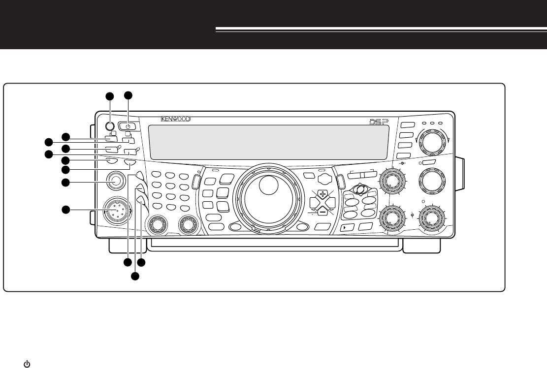
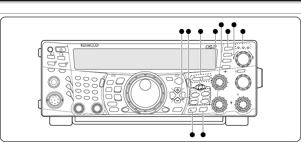
qPF key
You can assign a function to this Programmable
Function key. The default function is Voice 1
{page 77}.
w[ ] (POWER) switch
Press and hold briefly to switch the transceiver power
ON. Press again to switch the power OFF.
eATT/ F LOCK key
Press to switch the receiver attenuator ON or OFF
{page 57}. Press [FUNC], [ATT/ F LOCK] to switch
the Frequency Lock function ON or OFF {page 77}.
rPRE/ LOCK A key
Press to switch the receiver pre-amplifier ON or OFF
{page 57}. Press [FUNC], [PRE/ LOCK A] to lock all
the transceiver keys {page 77}.
tVOX/ LEVEL key
In voice mode, press to switch the Voice-Operated
Transmit function ON or OFF {page 39}. In CW
mode, press to switch the Break-in function ON or
OFF {page 42}. Press [FUNC], [VOX/ LEVEL] to
adjust the microphone input level for VOX operation.
The VOX LED lights orange when the VOX function is
active.
yPROC/ LEVEL key
Press to switch the Speech Processor for transmitting
ON or OFF {page 40}. Press [FUNC],
[PROC/ LEVEL] to adjust the Speech Processor
input level. The PROC LED lights orange when the
Speech Processor function is actived.
uSEND key
Press to switch the transceiver between receive
mode and transmit mode {pages 5, 7}.
iAT/ ANT1/2 key
Press to activate the internal antenna tuner {page 72}
or an external antenna tuner. Press [FUNC],
[AT/ ANT1/2] to select either Antenna 1 or Antenna 2
for the HF/ 50 MHz band {page 72}.
oPHONES jack
Connect a set of headphones to this jack. Inserting a
plug into the jack automatically mutes the audio from
the speaker {pages 3, 78}.
!0 MIC connector
Connect a compatible microphone to this connector,
then securely screw down the connector locking ring
{page 3}.
!1 N.R./ LEVEL key
Press to switch the DSP Noise Reduction function
ON or OFF. Press [FUNC], [N.R./ LEVEL] to adjust
the Noise Reduction level. Press [FUNC],
[N.R./ LEVEL] again to finish the adjustment
{page 56}.
!2 A.N./ LEVEL key
Press to switch the DSP Auto Notch function ON or
OFF. Press [FUNC], [A.N./ LEVEL] to adjust the
DSP Auto Notch reduction level. Press [FUNC],
[A.N./ LEVEL] again to finish the adjustment
{page 56}.
!3 B.C./ MANUAL key
Press to switch the DSP Auto Beat Cancel function
ON or OFF. Press [FUNC], [B.C./ MANUAL] to
adjust the beat cancel frequency manually. Press
[FUNC], [B.C./ MANUAL] again to finish the manual
adjustment {page 56}.
9
4 GETTING ACQUAINTED
PF
F LOCK A
1
CH1/REC
2
CH2/REC
3
CH3/REC
4
TONE/SEL
5
METER
6
CTCSS/SEL
7
NB/LEVEL
8
AGC/OFF
9
FINE/STEP
.
DCS/SEL
0
SHIFT/OFFSET
ENT
SEND
PHONES
MIC
AT
ANT1/2
PROC
LEVEL
VOX
ATT PRE
LEVEL
LEVEL
LEVEL
MANUAL
LO/
WIDTH
HI/
SHIFT
N.R.
A.N.
B.C.
FUNC
CALL
C.IN
CLR
MAIN
AUTO
CAR
TX MONI
DELAY NAR
REV
MIC
PWR
KEY
LSB
USB
CW
FSK
FM
AM
SUB
DISP
SEL
1MHz CTRL
MR
MG.SEL
M.IN
QUICK MEMO
M/S REV
TRACE
MAIN
MANUAL
RF
AF
SQL
SUB
CH
MULTI
BC MAIN
GAIN
VFO/CH
MENU TF-
SET
MAIN SUB
SG.SEL
SCAN M VFO M.IN
RIT
CW TUNE 9.6k STA
RIT/SUB
CON
XIT
ALT
SET
CLEAR
P.C .T
_+
HF/VHF/UHF ALL MODE MULTI BANDER TS-2000
SATL
A/B
VFO/M
SPLIT
A=B
17
18
15
14
16
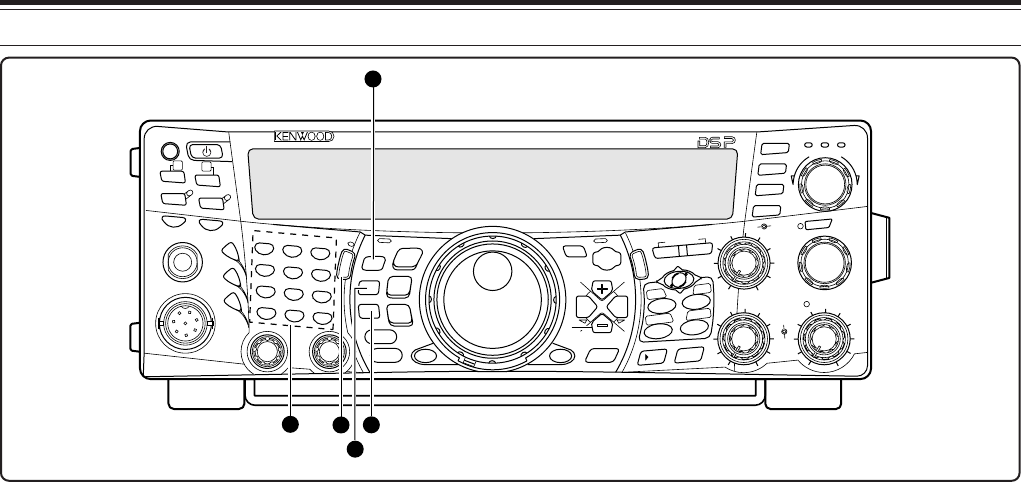
!4 Multi-purpose keypad
Consists of 10 keys that are used to enter numeric
data. Also used for the following functions:
•1/ CH1/REC, 2/ CH2/REC, and 3/ CH3/REC keys
Press to play back or record the CW or voice
messages that are associated with the DRU-3A
Digital Recording Unit {page 89} and the internal
electronic keyer {page 43}.
•4/ TONE/SEL key
Press to activate the sub-audible Tone function to
access repeaters for FM mode. To select the Tone
frequency, press [FUNC], [4/ TONE/SEL], then
select your desired tone frequency using the
MULTI/ CH control {page 33}.
•5/ METER key
Press to select the meter scales {page 19}.
•6/ CTCSS/SEL key
Press to activate the Continuous Tone Coded
Squelch System (CTCSS) function for FM mode.
To select the CTCSS tone frequency, press
[FUNC], [5/ CTCSS/SEL], then select your
desired CTCSS tone frequency using the
MULTI/ CH control {page 35}.
•7/ NB/LEVEL key
Press to switch the Noise Blanker ON or OFF.
Press [FUNC], [7/ NB/LEVEL] to adjust the Noise
Blanker level {page 57}.
•8/ AGC/OFF key
Press to adjust the response time of the Automatic
Gain Control. To switch the AGC OFF, press
[FUNC], [8/ AGC/OFF] {page 38}.
•9/ FINE/STEP key
Press to activate the Fine tuning function to allow
more precise tuning {page 38}.
••/ DCS/SEL key
Press to activate the Digital Coded Squelch
function for FM mode. To select the DCS code,
press [FUNC], [•/ DCS/SEL], then select your
desired code using the MULTI/ CH control
{page 36}.
•0/ SHIFT/OFFSET key
Press to switch the Shift function for FM mode ON
or OFF when accessing the repeaters. The Shift
frequency can be manually adjusted by pressing
[FUNC], [0/ SHIFT/OFFSET], then adjusting the
shift frequency value using the MULTI/ CH control
{page 32}.
•ENT key
Press to enter your desired frequency using the
keypad {page 37}.
!5 FUNC key
Press to access the secondary functions that are
assigned to the keys. While FUNC is active, the
FUNC LED lights orange.
!6 MIC/ CAR key
Press to adjust the microphone gain {page 20}.
While the Speech Processor function is ON, it
becomes the Speech Processor output level
adjustment key {page 40}.
Press [FUNC], [MIC/ CAR] to adjust the carrier level
for CW, FSK and AM mode {page 20}.
!7 PWR/ TX MONI key
Press to adjust the output power {page 20}. Press
[FUNC], [PWR/ TX MONI] to monitor your
transmission signal {page 79}.
!8 KEY/ DELAY key
Press to adjust the internal electronic keyer speed.
Press [FUNC], [KEY/ DELAY] to adjust the VOX
delay time or break-in time (Full break-in/ Semi
break-in time) for CW mode {page 42}.
10
4 GETTING ACQUAINTED
PF
F LOCK A
1
CH1/REC
2
CH2/REC
3
CH3/REC
4
TONE/SEL
5
METER
6
CTCSS/SEL
7
NB/LEVEL
8
AGC/OFF
9
FINE/STEP
.
DCS/SEL
0
SHIFT/OFFSET
ENT
SEND
PHONES
MIC
AT
ANT1/2
PROC
LEVEL
VOX
ATT PRE
LEVEL
LEVEL
LEVEL
MANUAL
LO/
WIDTH
HI/
SHIFT
N.R.
A.N.
B.C.
FUNC
CALL
C.IN
CLR
MAIN
AUTO
CAR
TX MONI
DELAY NAR
REV
MIC
PWR
KEY
LSB
USB
CW
FSK
FM
AM
SUB
DISP
SEL
1MHz CTRL
MR
MG.SEL
M.IN
QUICK MEMO
M/S REV
TRACE
MAIN
MANUAL
RF
AF
SQL
SUB
CH
MULTI
BCMAIN
GAIN
VFO/CH
MENU TF-
SET
MAIN SUB
SG.SEL
SCAN M VFO M.IN
RIT
CW TUNE 9.6k STA
RIT/SUB
CON
XIT
ALT
SET
CLEAR
P.C.T
_+
HF/VHF/UHF ALL MODE MULTI BANDER TS-2000
SATL
A/B
VFO/M
SPLIT
A=B
25
19
27 28 33
20 29
21 2223 24 26 30 32 31
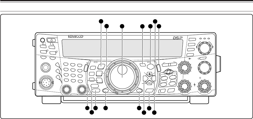
!9 LSB/ USB/ AUTO key
Press to select lower sideband (LSB) or upper
sideband (USB) mode for voice or digital operation.
Press [FUNC], [LSB/ USB/ AUTO] to toggle the auto
mode selection {page 73}.
@0 CW/ FSK/ REV key
Press to select CW or FSK (Frequency Shift Keying)
mode {pages 30, 51}. Press [FUNC],
[CW/ FSK/ REV] to reverse the sideband pitch.
@1 FM/ AM/ NAR key
Press to select FM or AM mode {pages 28, 29}.
Press [FUNC], [FM/ AM/ NAR] to select narrow
bandwidth transmission mode {page 29}.
@2 CLR key
Press to exit from, abort, or reset various functions.
Also used to erase memory channels {page 62} or
locking out memory channels from the scan list
{page 62}.
@3 DISP key
Press to toggle the normal operating mode and DSP
filter setting display mode {page 55}. Press and hold
to start the Visual Scan function {page 70}.
@4 1MHz/ SEL key
Press to switch the MHz Up/ Down function ON or
OFF using the MULTI/ CH control. Press [FUNC],
[1MHz/ SEL] to change the increment/ decrement
step value {page 37}. Press and hold to start the
MHz Scan function {page 68}.
@5 Tuning control
Turn to select the desired frequency {page 37}. Use
the convenient finger-tip cavity for continuous tuning.
The lever behind this control adjusts the control
torque level; turn fully clockwise for light torque or
fully counterclockwise for heavy torque.
@6 CTRL key
Press to toggle the operating controls between the
main transceiver and the sub-receiver. The
transmission band is not affected by this key.
@7 MENU key
Press to select or cancel the Menu mode that is used
for activating and configuring functions {page 21}.
@8 TF-SET key
While operating split-frequency, press to monitor or
change your transmit frequency {page 31}.
@9 +/ – (Up/ Down) keys
Press to step through all the Amateur radio bands
consecutively {page 18}. Also used to make
selections from the Menu {page 21}, and to check the
Start and End frequencies of the Scan function
{page 62}.
#0 MAIN key
Press to transfer the operating controls to the MAIN
transceiver. Also moves the transmission band to the
main transceiver frequency.
#1 SUB key
Press to transfer the operating controls to the sub-
receiver. Also moves the transmission band to the
sub-receiver frequency.
#2 SCAN/ SG.SEL key
Press to start or stop the Scan function {page 66}.
Press [FUNC], [SCAN/ SG.SEL] to select a scan
group {page 69}.
#3 CALL/ C.IN key
Press to recall a call channel for the selected operating
band (HF/ 50 MHz/ 144 MHz/ 430 (440) MHz/ 1.2 GHz
(TS-2000/ TS-B2000 Optional)). Press [FUNC],
[CALL/ C.IN] to write a new Call Channel to the
memory {page 75}.
11
4 GETTING ACQUAINTED
HF/VHE/UHF ALL MODE MULTI BANDER TS-2000
PF
F LOCK A
1
CH1/REC
2
CH2/REC
3
CH3/REC
4
TONE/SEL
5
METER
6
CTCSS/SEL
7
NB/LEVEL
8
AGC/OFF
9
FINE/STEP
.
DCS/SEL
0
SHIFT/OFFSET
ENT
SEND
PHONES
MIC
AT
ANT1/2
PROC
LEVEL
VOX
ATT PRE
LEVEL
LEVEL
LEVEL
MANUAL
LO/
WIDTH
HI/
SHIFT
N.R.
A.N.
B.C.
FUNC
CALL
C.IN
CLR
MAIN
AUTO
CAR
TX MONI
DELAY NAR
REV
MIC
PWR
KEY
LSB
USB
CW
FSK
FM
AM
SUB
DISP
SEL
1MHz CTRL
MR
MG.SEL
M.IN
QUICK MEMO
M/S REV
TRACE
MAIN
MANUAL
RF
AF
SQL
SUB
CH
MULTI
BC MAIN
GAIN
VFO/CH
MENU TF-
SET
MAIN SUB
SG.SEL
SCAN M VFO M.IN
RIT
CW TUNE 9.6k STA
RIT/SUB
CON
XIT
ALT
SET
CLEAR
P.C .T
_+
HF/VHF/UHF ALL MODE MULTI BANDER TS-2000
SATL
A/B
VFO/M
SPLIT
A=B
36 35
4041
4234 4339
37 38
#4 QUICK MEMO keys
Controls the Quick Memory function {page 64}.
•MR key
Press to recall data from the Quick Memory
{page 65}.
•M.IN key
Press to write data into the Quick Memory
{page 64}.
#5 SATL key
Press to activate Satellite communication mode
{page 53}.
#6 Frequency control keys
These keys control functions related to selecting a
frequency, a VFO, or a memory channel.
•A/B / M/S key
Press to select either VFO A or VFO B {page 18}.
In Satellite mode, press to swap the MAIN and
SUB frequencies so that you can change the
frequencies with a Tuning control {page 54}.
•SPLIT/ REV key
Press to use split-frequency operation which
allows you to use different transmit and receive
frequencies {page 31}. In Satellite mode, press to
toggle the Trace Reverse function ON and OFF
{page 54}.
•VFO/M / VFO/CH key
Press to select either Memory or VFO mode
{page 59}. In Satellite mode, press to toggle the
VFO and memory channel operations {page 54}.
•A=B/ TRACE key
Press to copy the data in the currently selected
VFO to the other VFO {page 31}. In Satellite
mode, press to toggle the TRACE function ON and
OFF {page 54}.
#7 Mss
ss
sVFO/ MG.SEL key
Press to transfer data from a memory channel to a
VFO {page 61}. Press [FUNC], [Mss
ss
sVFO/ MG.SEL]
to enter Memory Group Select mode {page 64}.
#8 M.IN key
Writes data into a memory channel {page 58} or
selects Memory Scroll mode {page 60}.
#9 RIT/ CW TUNE key
Press to switch the Receive Incremental Tuning
function ON or OFF {page 38}. Press [FUNC],
[RIT/ CW TUNE] to activate the automatic zero-beat
function for CW mode {page 30}.
$0 XIT/ ALT key
Press to switch the Transmit Incremental Tuning
function ON or OFF {page 40}. Press [FUNC],
[XIT/ ALT] to switch the Auto Lock Tuning mode for
the 1.2 GHz band (FM) ON or OFF {page 72}.
$1 CLEAR key
Press to reset the RIT/XIT frequency offset to zero
{pages 38, 40}.
$2 SET/ P.C.T. key
Press to set received DX Packet Cluster frequency
data to the main transceiver when the Packet Cluster
Tune mode is activated. Press [FUNC], [SET/ P.C.T.]
to switch the Packet Cluster Tune mode ON or OFF
{page 53}.
$3 TNC Status Indicators
• 9.6k LED
Lights when the internal TNC is operating at
9600 bps. The default operating mode is
1200 bps {page 50}.
• STA LED
Lights when the internal TNC holds the data in the
buffer to transmit.
• CON LED
Lights when the internal TNC is connected to
another TNC.
12
4 GETTING ACQUAINTED
PF
F LOCK A
1
CH1/REC
2
CH2/REC
3
CH3/REC
4
TONE/SEL
5
METER
6
CTCSS/SEL
7
NB/LEVEL
8
AGC/OFF
9
FINE/STEP
.
DCS/SEL
0
SHIFT/OFFSET
ENT
SEND
PHONES
MIC
AT
ANT1/2
PROC
LEVEL
VOX
ATT PRE
LEVEL
LEVEL
LEVEL
MANUAL
LO/
WIDTH
HI/
SHIFT
N.R.
A.N.
B.C.
FUNC
CALL
C.IN
CLR
MAIN
AUTO
CAR
TX MONI
DELAY NAR
REV
MIC
PWR
KEY
LSB
USB
CW
FSK
FM
AM
SUB
DISP
SEL
1MHz CTRL
MR
MG.SEL
M.IN
QUICK MEMO
M/S REV
TRACE
MAIN
MANUAL
RF
AF
SQL
SUB
CH
MULTI
BC MAIN
GAIN
VFO/CH
MENU TF-
SET
MAIN SUB
SG.SEL
SCAN M VFO M.IN
RIT
CW TUNE 9.6k STA
RIT/SUB
CON
XIT
ALT
SET
CLEAR
P.C .T
_+
HF/VHF/UHF ALL MODE MULTI BANDER TS-2000
SATL
A/B
VFO/M
SPLIT
A=B
474654 55 4445
5352 51504948
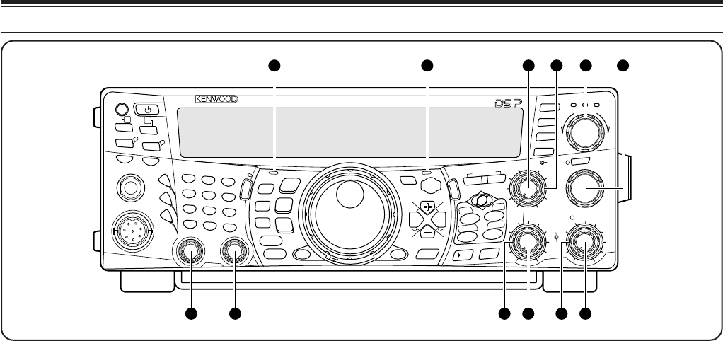
$4 RIT/SUB control
After switching the RIT or XIT function ON, turn this
control to select the desired frequency offset
{pages 38, 40}.
Turn to adjust the sub-receiver frequency when the
RIT and XIT functions are switched OFF and the sub-
receiver is switched ON {page 45}.
$5 MANUAL BC control
Turn to adjust the audio notch frequency while the
DSP beat cancel function is set to the manual
frequency adjustment mode {page 56}.
$6 MAIN RF GAIN control
Turn to adjust the radio frequency gain for the main
transceiver {page 18}.
$7 MULTI/ CH control
In VFO mode, rotate to step the operating frequency
up or down {page 37}. In memory channel mode,
rotate to select a memory channel {page 58}. Also
used for selecting Menu numbers when accessing the
Menu mode {page 21} and as a selector to choose
settings for various functions activated by front panel
buttons. The MULTI/ CH LED lights when the
setting(s) can be changed using the MULTI/ CH
control.
$8 MAIN SQL control
Used for muting (“squelching”) the speaker, the head
phones and AF output on ACC2 (13-pin DIN
connector) when no receive signal is present on the
main transceiver {page 19}.
$9 MAIN AF control
Turn to adjust the volume on the main transceiver
{page 19}.
%0 SUB SQL control
Used for muting (“squelching”) the speaker, head
phone and AF output on ACC2 (13-pin DIN
connector) when no receive signal is present on the
sub-receiver {page 46}.
%1 SUB AF control
Press to switch the sub-receiver ON or OFF. When it
is ON, the SUB-receiver LED lights orange.
Turn to adjust the volume for the sub-receiver.
%2 LO/ WIDTH control
Turn clockwise/ counterclockwise to increase/
decrease the value for the low cut-off DSP filter
frequency or the filter bandwidth (CW/ FSK). The
selected value appears on the main dot-matrix
display {page 55}.
%3 HI/ SHIFT control
Turn clockwise/ counterclockwise to increase/
decrease the value for the high cut-off DSP filter
frequency or the Shift frequency. The selected value
appears on the sub dot-matrix display {page 55}.
%4 MAIN band LED
Lights green while the main transceiver’s squelch is
open. Lights red while transmitting on the main
transceiver’s VFO band.
%5 SUB band LED
Lights green while the sub-receiver’s squelch is open.
Lights red while transmitting on the sub-receiver’s
VFO band.
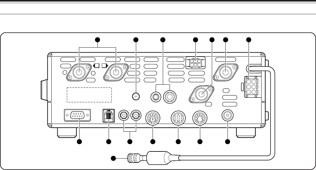
13
4 GETTING ACQUAINTED
REAR PANEL
EXT. SP2
8Ω
PANELCOM
ANT 2 ANT 1
ANT
144
AT ANT 1.2G
DC
13.8V
ANT
430
EXT. SP1
8ΩACC2
EXT. CONT
REMOTE
HF
RX ANT
PADDLE
KEY
GND
2 1
1
9
10 12 13 14 1511
32 4 5 86
7
qANT 1 and ANT 2 connectors
Connect your primary HF/ 50 MHz antenna to ANT 1. If
you are using 2 antennas for the HF/ 50 MHz band,
connect the secondary antenna to the ANT 2 connector.
wGND post
Connect a heavy gauge wire or copper strap between
the ground post and the nearest earth ground {page 1}.
eKEY and PADDLE jacks
The PADDLE jack mates with a 6.3 mm (1/4")
3-conductor plug for connecting a keyer paddle to the
internal electronic keyer. The KEY jack mates with a
3.5 mm (1/8") 2-conductor plug for connecting an
external key for CW operation. Read “Keys for CW
(PANEL and KEY)” {page 3} before using these jacks.
rAT connector
Mates with the connector on the cable supplied with
the external antenna tuner. Refer to the instruction
manual supplied with the tuner for more information.
tANT 144
Connect your 144 MHz band antenna to this connector.
yANT 430
Connect your 430/ 440 MHz band antenna to this
connector.
uANT 1.2G (TS-2000/ TS-B2000 Optional)
Connect your 1.2 GHz band antenna to this connector.
iDC 13.8V power input connector
Connect a 13.8 V DC power source to this connector
{page 2}. Use the cable supplied with the regulated
DC power supply.
oCOM connector
Mates with a 9-pin female RS-232C connector for
connecting a computer via one of its serial
communication ports {page 93}. Also used with the
Quick Data Transfer function {page 93}.
!0 PANEL connector
Connect a cable from the optional separate remote
panel (RC-2000) to this connector.
!1 EXT.SP1 and EXT.SP2 jacks
Mate with a 3.5 mm (1/8"), 2-conductor (mono) plugs
for connecting external speakers {pages 3, 78}.
!2 EXT.CONT connector
Connect your 50 MHz, 144 MHz, 430/ 440 MHz or
1.2 GHz linear amplifier control cable to this
connector {page 76}.
!3 ACC2 connector
Mates with a 13-pin male DIN connector for
connecting various accessory equipment, such as an
external TNC/ MCP or a RTTY terminal {page 94}.
!4 REMOTE connector
Mates with a 7-pin male DIN connector for connecting
an HF linear amplifier {page 76}. Do not connect
50 MHz, 144 MHz, 430/ 440 MHz, or 1.2 GHz linear
amplifier controls to this connector; use the
EXT.CONT connector instead.
!5 HF RX ANT connector
Connect a separate receive-only antenna for HF low
bands to this jack (RCA connector) {page 76}.
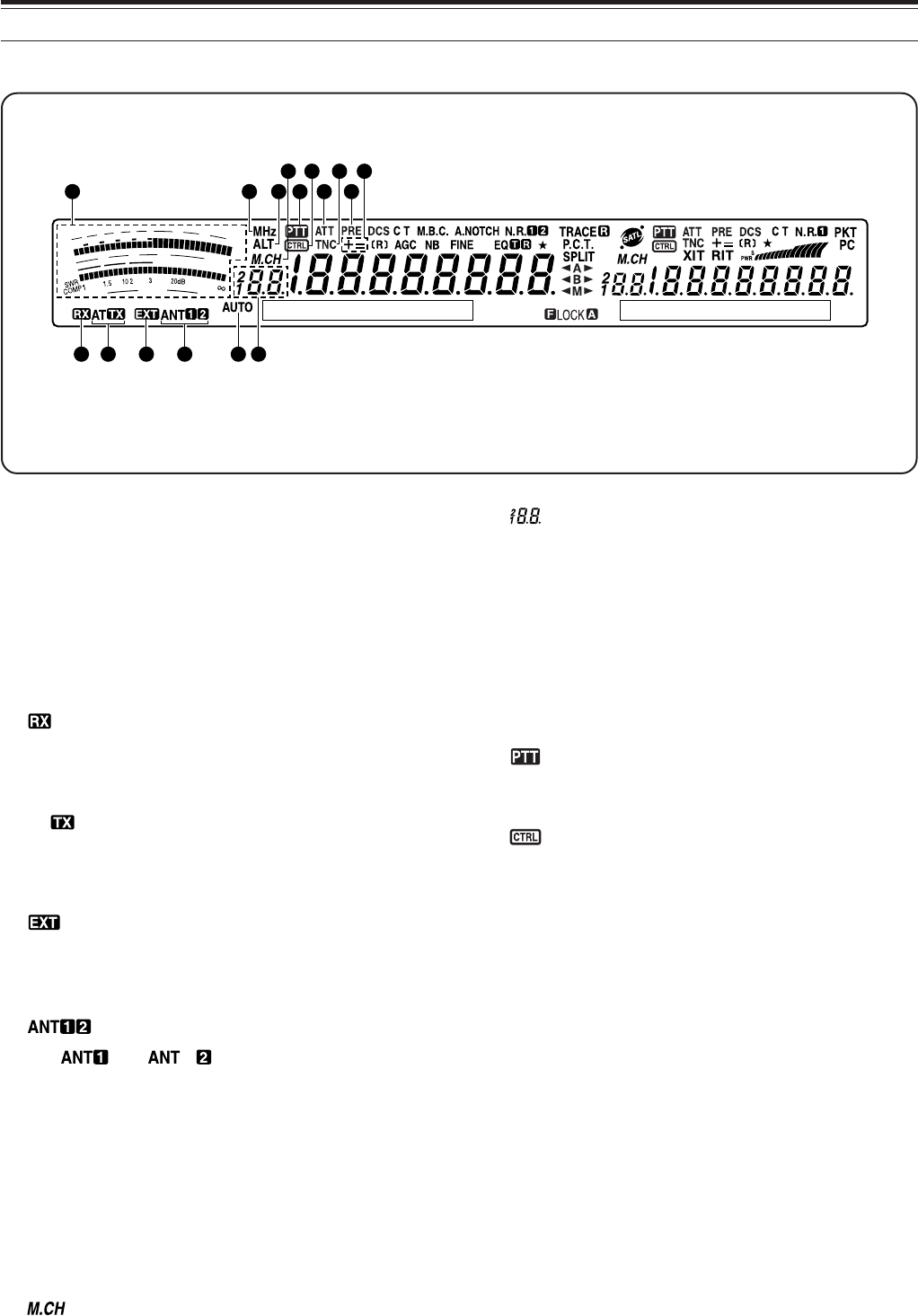
14
4 GETTING ACQUAINTED
DISPLAY
F
I
L
T
E
R
S
1
3
5
7
9
2
0
4
0
6
0
d
B
P
W
R
1
0
2
5
5
0
1
0
0
W
%
A
L
C
61
2 4
10
93 5
11 13 15
7
8
12 14 16
qMETER
While receiving, serves as an S-meter to measure
and display the received signal strength. It also
displays the filter width. While transmitting, serves as
a power meter plus an ALC meter, an SWR meter, or
a Speech Processor compression meter. The Peak
Hold function holds each reading for approximately
half a second.
Note: SWR meter works only for the HF and 50 MHz bands.
w
Appears while the internal antenna tuner {page 72} or
an external antenna tuner is in-line for the HF/ 50 MHz
band reception.
eAT
Appears while the internal antenna tuner {page 72} or
an external antenna tuner is in-line for the HF/ 50 MHz
band transmission.
r
Appears while HF RX ANT {page 76} connector is
enabled to receive HF band signals. You cannot
transmit the signals though this connector.
t
Either “ ” or “ ” appears, depending on
whether the Antenna 1 connector or the Antenna 2
connector is selected for the HF/ 50 MHz band
{page 72}.
yMHz
Appears when the MHz Up/ Down mode using the
MULTI/ CH control is switched ON {page 37}.
uALT
Appears when ALT (Auto Lock Tuning) is activated for
the 1.2 GHz (FM) band {page 72}.
i
Appears while Memory Recall or Memory Scroll is
being used {page 59}.
o
Shows the memory channel number for the main
transceiver. If you select a channel over 99, a
leading digit (1 or 2) appears (the memory number
ranges from 00 to 299). It also shows the Quick
Memory number location (the Quick Memory number
ranges from “0_” to “9_”).
!0 AUTO
Appears when Auto mode selection is activated
{page 73}.
!1
Appears when the main transceiver is selected for the
transmission band.
!2
Appears when the main transceiver’s functions can
be controlled using the front panel keys.
!3 ATT
Appears when the main transceiver’s receiver
attenuator (approx. 12 dB) is ON {pages 57, 73}.
!4 TNC
Appears when the internal TNC is assigned to the
main transceiver {page 49}.
!5 PRE
Appears when the receiver pre-amplifier of the main
transceiver is ON {page 57}.
!6 + =
“+” or “–” appears, indicating which offset direction is
selected for the main transceiver. “=” appears when
the –7.6 MHz (430 MHz) or –6.0 MHz (1.2 GHz)
offset is selected (all E-types only) {page 32}.
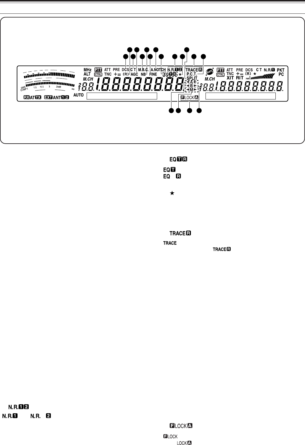
15
4 GETTING ACQUAINTED
F
I
L
T
E
R
S
1
3
5
7
9
2
0
4
0
6
0
d
B
P
W
R
1
0
2
5
5
0
1
0
0
W
%
A
L
C
3331 3234
2117 19 23 25 282726 29
302218 2420
!7 DCS
Appears when the DCS (Digital Code Squelch) of the
main transceiver is ON {page 36}.
!8 [R]
“R” appears when the Reverse function of the main
transceiver is ON. “[R]” appears when the ASC
(Automatic Simplex Check) of the main transceiver is
activated {page 34}.
!9 C T
“T” appears when the Tone function of the main
transceiver is ON {page 33}. “C T” appears when the
Continuous Tone Coded Squelch System (CTCSS) of
the main transceiver is ON {page 35}.
@0 AGC
Appears when the AGC (Automatic Gain Control) of
the main transceiver is ON {page 38}. Disappears
when the AGC is OFF.
@1 M.B.C.
“B.C.” appears when the automatic Beat Canceller is
ON. “M.B.C.” appears when the single Beat Cancel
frequency is manually controlled {page 56}.
@2 NB
Appears when the Noise Blanker is ON {page 57}.
@3 FINE
Appears when the Fine function for the main Tuning
control is ON {page 38}.
@4 A.NOTCH
Appears when the DSP Auto Notch function of the
main transceiver is ON {page 56}.
@5
“” or “ ” appears, depending on whether
DSP Noise Reduction 1 (Line Enhanced method) or
Noise Reduction 2 (SPAC method) of the main
transceiver is selected {page 56}.
@6
“” appears when the TX Equalizer function is ON.
“” appears when the RX Equalizer function of
the main transceiver is ON {pages 41, 78}.
@7
Appears when the Quick Menu function of the
transceiver is ON {page 21}. It also appears when
the frequency point of Program Scan Partially Slowed
is selected on the main-transceiver {page 67}.
@8
“” appears when the Trace function is ON while
in Satellite mode. “ ” appears when the
Reverse Trace function is ON {page 53}.
@9 P.C.T.
Appears when Packet Cluster Tune mode is ON
{page 53}.
#0 SPLIT
Appears when the transmit frequency differs from the
receive frequency {page 31}.
#1 tAs
“tA” or “As” appears while VFO A is selected
{page 18}. “A” appears while Menu A is being
accessed {page 21}.
#2 tBs
“tB” or “Bs” appears while VFO B is selected
{page 18}. “B” appears while Menu B is being
accessed {page 21}.
#3 tMs
“tM” or “Ms” appears while a simplex memory
channel is selected {page 59}. “tMs” appears
while a split frequency memory channel is selected
{page 60}.
#4
“” appears when the Frequency Lock function is
ON. “ ” appears when the Lock All key function
is ON {page 77}.
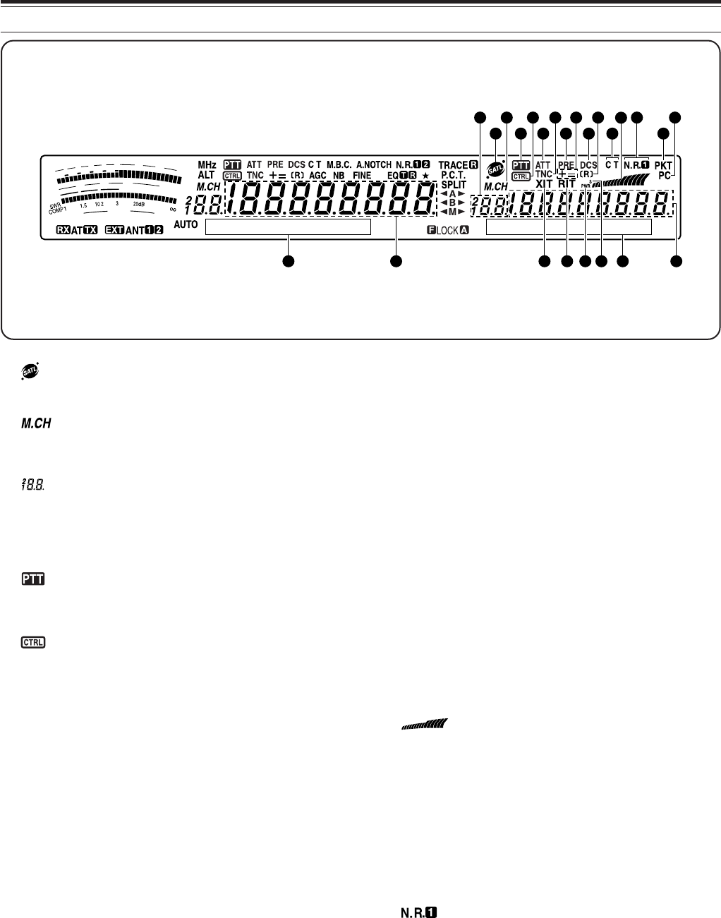
16
4 GETTING ACQUAINTED
F
I
L
T
E
R
S
1
3
5
7
9
2
0
4
0
6
0
d
B
P
W
R
1
0
2
5
5
0
1
0
0
W
%
A
L
C
57 55 5842 45 49 48 56
38 40 43 534635 51
39 41 47 5452443637 50
#5
Appears while in Satellite mode {page 53}.
#6
Appears while Memory Recall or Memory Scroll is
being used for the sub-receiver {page 59}.
#7
Shows the memory channel number for the sub-
receiver. If you select a channel over 99, a leading
digit (1 or 2) appears (the memory number ranges
from 00 to 299).
#8
Appears when the sub-receiver is selected for the
transmission band.
#9
Appears when the sub-receiver’s functions can be
controlled using the front panel keys.
$0 ATT
Appears when the sub-receiver’s receive attenuator
(approx. 12 dB) is ON {pages 57, 73}.
$1 TNC
Appears when the internal TNC is assigned to the
sub-receiver.
$2 XIT
Appears when Transmit Incremental Tuning of the
main transceiver is ON {page 40}.
$3 PRE
Appears when the receiver pre-amplifier of the sub-
receiver is ON {page 57}.
$4 + =
“+” or “–” appears, indicating which offset direction is
selected for the sub-receiver. “=” appears when the
–7.6 MHz (430 MHz) or –6.0 MHz (1.2 GHz) offset is
selected (all E-types only) {page 32}.
$5 RIT
Appears when Receive Incremental Tuning of the
main transceiver is ON {page 38}.
$6 DCS
Appears when the DCS (Digital Code Squelch) of the
sub-receiver is ON {page 36}.
$7 [R]
“R” appears when the Reverse function of the sub-
receiver is ON. “[R]” appears when the ASC
(Automatic Simplex Check) of the sub-receiver is
activated {page 34}.
$8 S
Appears when the sub-receiver meter shows the
signal strength level {page 46}.
$9 PWR
Appears when the sub-receiver meter shows the
output power level {page 20}.
%0
Serves as an S-meter to measure and display the
received signal strength for the sub-receiver. It also
displays the relative output power when the sub-band
is selected for the transmission.
%1 C T
“T” appears when the Tone function of the sub-
receiver is ON {page 33}. “C T” appears when the
Continuous Tone Coded Squelch System (CTCSS) of
the sub-receiver is ON {page 35}.
%2
Appears when the DSP Noise Reduction 1 of the sub-
receiver is activated {page 56}.
%3 PKT
Appears when the internal TNC is operating in Packet
mode {page 49}.
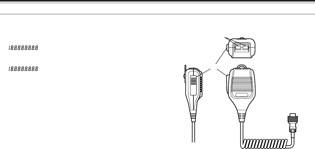
17
4 GETTING ACQUAINTED
%4 PC
Appears when the TS-2000(X) is being controlled by
a PC {page 81}.
%5
The main transceiver operating frequency display.
%6
When the sub-receiver is switched ON, it shows the
receive frequency for the sub-receiver. However, if
you are controlling the main transceiver functions,
such as RIT, XIT, or SPLIT, it is used to display the
frequency information for these functions {page 45}.
%7 MAIN dot-matrix display
In the normal operating mode, it displays the
operating mode for the main transceiver. It is also
used to display various control information, such as
menu numbers and settings and the DSP filter
configuration.
%8 SUB dot-matrix display
In the normal operating mode, it displays the
operating mode for the sub-receiver. It is also used
to display various control information, such as menu
information and the DSP filter frequency
configuration.
MICROPHONE
PTT
DWN UP
q
w
qUP/ DWN keys
Use these keys to step the VFO frequency, memory
channels, or Menu selections up and down. Press
and hold these keys to continuously change the
settings.
wPTT (Push-to-Talk) switch
The transceiver is placed in transmit mode when this
non-locking switch is held down. Releasing the
switch returns the transceiver to receive mode.
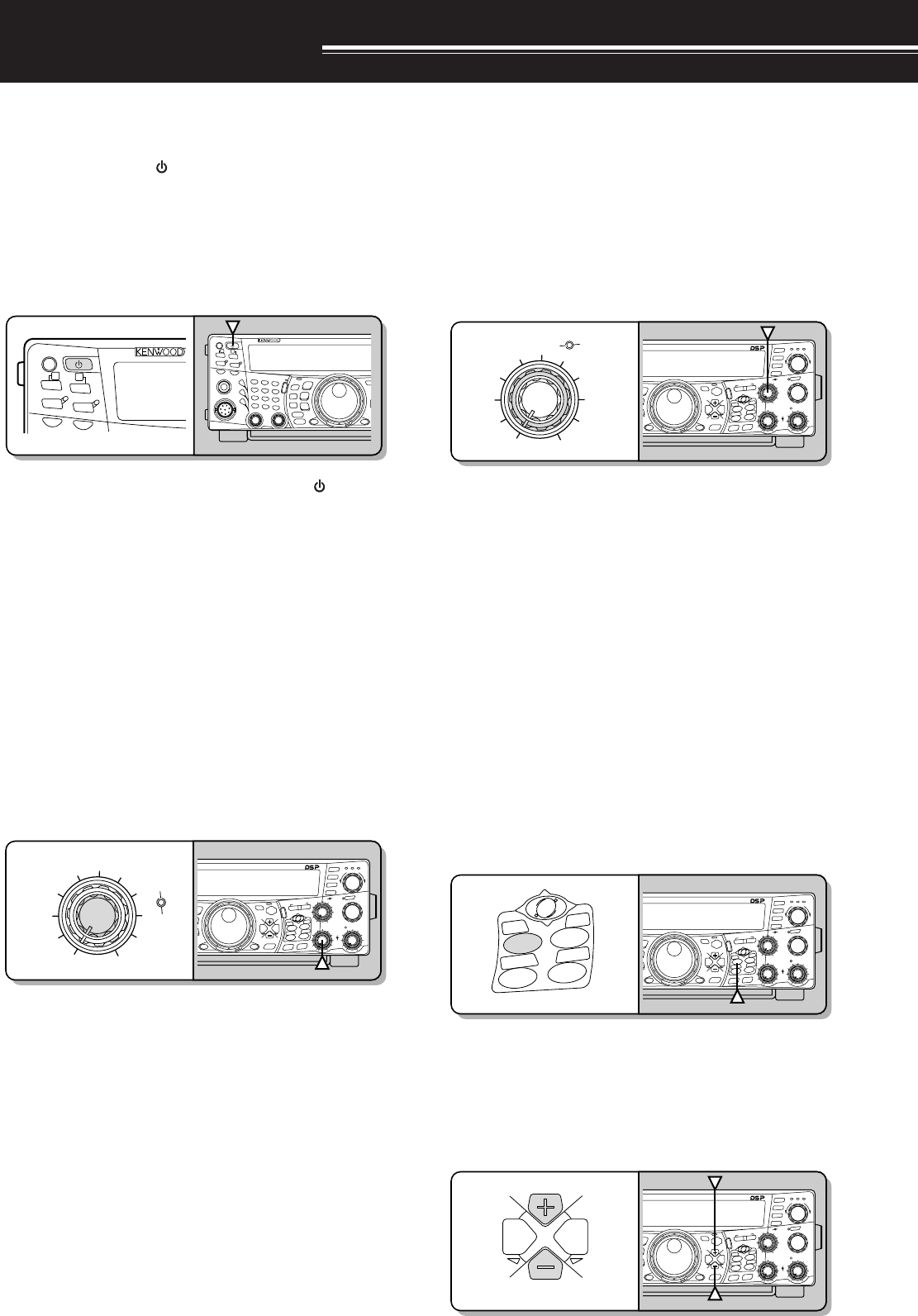
18
OPERATING BASICS
SWITCHING POWER ON/OFF
1Switch the DC power supply ON.
2Press and hold [ ] (POWER) briefly to switch
the transceiver ON.
• Do not press the switch for more than
approximately 2 seconds; the transceiver will
be switched OFF.
• Upon power up, “HELLO” appears, followed by
the selected frequency and other indicators.
PF
F LOCK A
SEND AT
ANT1/2
PROC
LEVEL
VOX
ATT PRE
LEVEL
PF
F LOCK A
1
CH1/REC
2
CH2/REC
3
CH3/REC
4
TONE/SEL
5
METER
6
CTCSS/SEL
7
NB/LEVEL
8
AGC/OFF
9
FINE/STEP
.
DCS/SEL
0
SHIFT/OFFSET
ENT
SEND
PHONES
MIC
AT
ANT1/2
PROC
LEVEL
VOX
ATT PRE
LEVEL
LEVEL
LEVEL
MANUAL
LO/
WIDTH
HI/
SHIFT
N.R.
A.N.
B.C.
FUNC
CLR
MAIN
AUTO
CAR
TX MONI
DELAY NAR
REV
MIC
PWR
KEY
LSB
USB
CW
FSK
FM
AM
DISP
SEL
1MHz CTRL
ME
N
M
HF/VHE/UHF ALL M
O
3To switch the transceiver OFF, press [ ]
(POWER) again.
4Switch the DC power supply OFF.
• You may skip step 3. After switching the
transceiver ON, you can switch it OFF or ON
using only the power switch of the DC power
supply. The transceiver stores the information
of the POWER switch position when the DC
power source is switched OFF.
ADJUSTING VOLUME
AUDIO FREQUENCY (AF) GAIN
Turn the MAIN AF control clockwise to increase the
audio level and counterclockwise to decrease the
level.
MAIN
CALL
C.IN
U
TO
S
B
S
B
SUB
S
EL
1MHz CTRL
MR
M VFO
MG.SEL
M.IN
M.IN
QUICK MEMO
SATL
A/B
M/S REV
TRACE
MAIN
MANUAL
RF
AF
SQL
SUB
CH
MULTI
BCMAIN
GAIN
VFO/CH
VFO/M A=B
SPLIT
MENU TF-
SET
MAIN SUB
SG.SEL
SCAN
RIT
CW TUNE 9.6k STA
RIT/SUB
CON
XIT
ALT
SET
CLEAR
P.C . T
_+
HF/VHE/UHF ALL MODE MULTI BANDER TS-2000
AF
SQL
Note:
◆
The position of the MAIN AF control does not affect the volume
of beeps caused by pressing keys nor the CW transmit sidetone.
The audio level for Packet operation is also independent of the
MAIN AF control setting.
◆
When the optional RC-2000 is installed, you can control the
volume with the AF controls on both the transceiver and the
RC-2000. However, when turning the transceiver on, the volume
settings of the RC-2000 have priority.
RADIO FREQUENCY (RF) GAIN
Set the MAIN RF GAIN control fully clockwise. You
may turn it counterclockwise slightly when you have
trouble hearing the desired signal because of
excessive atmospheric noise or interference from
other stations. First take note of the peak S-meter
reading of the desired signal. Then turn the MAIN RF
GAIN control counterclockwise until the S-meter
reads the peak value that you noted. Signals that are
weaker than this level will be attenuated and
reception of the station will become easier.
MANUAL
RF
BC MAIN
GAIN
CALL
C.IN
U
TO
S
B
S
B
SUB
S
EL
1MHz CTRL
MR
M VFO
MG.SEL
M.IN
M.IN
QUICK MEMO
SATL
A/B
M/S REV
TRACE
MAIN
MANUAL
RF
AF
SQL
SUB
CH
MULTI
BCMAIN
GAIN
VFO/CH
VFO/M A=B
SPLIT
MENU TF-
SET
MAIN SUB
SG.SEL
SCAN
RIT
CW TUNE 9.6k STA
RIT/SUB
CON
XIT
ALT
SET
CLEAR
P. C . T
_+
HF/VHE/UHF ALL MODE MULTI BANDER TS-2000
Depending on the type and gain of your antenna, and
the condition of the band, you may also prefer leaving
the MAIN RF GAIN control turned counterclockwise
by the same amount rather than turning it fully
clockwise. When using FM mode, always set the
MAIN RF GAIN control fully clockwise.
SELECTING VFO A OR VFO B
2 VFOs are available for controlling the frequency on
the main transceiver. Each VFO, VFO A and VFO B,
works independently so that a different frequency and
mode can be selected. When SPLIT operation is
activated, VFO A is used for reception and VFO B is
used for transmission. The opposite combination is
also possible.
Press [A/B] to toggle between VFO A and VFO B.
•“tA” or “tB” appears to indicate which VFO is
selected.
SATL
A/B
M/S REV
TRACE
VFO/CH
VFO/M A=B
SPLIT
CALL
C.IN
U
TO
S
B
S
B
SUB
S
EL
1MHz CTRL
MR
M VFO
MG.SEL
M.IN
M.IN
QUICK MEMO
SATL
A/B
M/S REV
TRACE
MAIN
MANUAL
RF
AF
SQL
SUB
CH
MULTI
BCMAIN
GAIN
VFO/CH
VFO/M A=B
SPLIT
MENU TF-
SET
MAIN SUB
SG.SEL
SCAN
RIT
CW TUNE 9.6k STA
RIT/SUB
CON
XIT
ALT
SET
CLEAR
P. C . T
_+
HF/VHE/UHF ALL MODE MULTI BANDER TS-2000
SELECTING A BAND
Press [+]/ [–] to select your desired band.
• Holding down either key changes the bands
continuously.
MAIN
SUB
CALL
C.IN
U
TO
S
B
S
B
SUB
S
EL
1MHz CTRL
MR
M VFO
MG.SEL
M.IN
M.IN
QUICK MEMO
SATL
A/B
M/S REV
TRACE
MAIN
MANUAL
RF
AF
SQL
SUB
CH
MULTI
BCMAIN
GAIN
VFO/CH
VFO/M A=B
SPLIT
MENU TF-
SET
MAIN SUB
SG.SEL
SCAN
RIT
CW TUNE 9.6k STA
RIT/SUB
CON
XIT
ALT
SET
CLEAR
P. C . T
_+
HF/VHE/UHF ALL MODE MULTI BANDER TS-2000
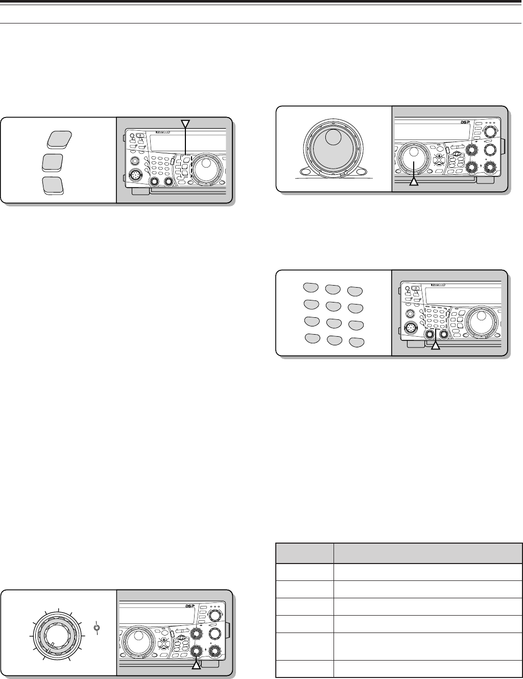
19
5 OPERATING BASICS
SELECTING A MODE
Press [LSB/ USB/ AUTO], [CW/ FSK/ REV], or
[FM/ AM/ NAR]. To select the second mode on each
key, press the same key again. For example, each
press of [LSB/ USB/ AUTO] toggles between LSB
and USB mode.
AUTO
NAR
REV
LSB
USB
CW
FSK
FM
AM
PF
F LOCK A
1
CH1/REC
2
CH2/REC
3
CH3/REC
4
TONE/SEL
5
METER
6
CTCSS/SEL
7
NB/LEVEL
8
AGC/OFF
9
FINE/STEP
.
DCS/SEL
0
SHIFT/OFFSET
ENT
SEND
PHONES
MIC
AT
ANT1/2
PROC
LEVEL
VOX
ATTPRE
LEVEL
LEVEL
LEVEL
MANUAL
LO/
WIDTH
HI/
SHIFT
N.R.
A.N.
B.C.
FUNC
CLR
MAIN
AUTO
CAR
TX MONI
DELAY NAR
REV
MIC
PWR
KEY
LSB
USB
CW
FSK
FM
AM
DISP
SEL
1MHz CTRL
ME
N
M
HF/VHE/UHF ALL M
O
Press [FUNC], [LSB/ USB/ AUTO] to toggle the
Auto Mode selection. When it is active, “AUTO”
appears. If you change the frequency above or
below 9.5 MHz, the transceiver automatically
switches modes; LSB for frequencies under 9.5 MHz
and USB for frequencies equal to or above 9.5 MHz
(HF/ 50 MHz band). As for the 144 MHz,
430/ 440 MHz, and 1.2 GHz bands, the transceiver
automatically changes the operating mode to FM.
You can further add the frequency table data to
change the mode automatically
{page 73}.
ADJUSTING SQUELCH
The purpose of the Squelch is to mute the speaker
when no signals are present. With the squelch level
correctly set, you will hear sound only while actually
receiving signals. The higher the selected squelch
level, the stronger the signals must be to receive.
The appropriate squelch level depends on the
ambient RF noise conditions.
Turn the MAIN SQL control, when there are no
signals present, to select the squelch level at which
the background noise is just eliminated; the MAIN
band LED will turn off. Many ham operators prefer
leaving the MAIN SQL control fully counterclockwise
unless operating on a full-carrier mode such as FM.
The squelch level for the main transceiver is preset
at the factory to approximately 9 o’clock for FM and
11 o’clock for SSB and AM.
MAIN
CALL
C.IN
U
TO
S
B
S
B
SUB
S
EL
1MHz CTRL
MR
M VFO
MG.SEL
M.IN
M.IN
QUICK MEMO
SATL
A/B
M/S REV
TRACE
MAIN
MANUAL
RF
AF
SQL
SUB
CH
MULTI
BCMAIN
GAIN
VFO/CH
VFO/M A=B
SPLIT
MENU TF-
SET
MAIN SUB
SG.SEL
SCAN
RIT
CW TUNE 9.6k STA
RIT/SUB
CON
XIT
ALT
SET
CLEAR
P.C . T
_+
HF/VHE/UHF ALL MODE MULTI BANDER TS-2000
AF
SQL
SELECTING A FREQUENCY
Turn the Tuning control clockwise or press Mic [UP]
to increase the frequency. Turn the Tuning control
counterclockwise or press Mic [DWN] to decrease the
frequency.
SEL
1MHz CTRL
CALL
C.IN
U
TO
S
B
S
B
SUB
S
EL
1MHz CTRL
MR
M VFO
MG.SEL
M.IN
M.IN
QUICK MEMO
SATL
A/B
M/S REV
TRACE
MAIN
MANUAL
RF
AF
SQL
SUB
CH
MULTI
BCMAIN
GAIN
VFO/CH
VFO/M A=B
SPLIT
MENU TF-
SET
MAIN SUB
SG.SEL
SCAN
RIT
CW TUNE 9.6k STA
RIT/SUB
CON
XIT
ALT
SET
CLEAR
P. C . T
_+
HF/VHE/UHF ALL MODE MULTI BANDER TS-2000
You may prefer directly entering a frequency using
the numeric keypad if the desired frequency is far
from the current frequency. Press [ENT], then press
the numeric keys as necessary. For details, see
“Direct Frequency Entry” {page 37}.
1
CH1/REC
2
CH2/REC
3
CH3/REC
4
TONE/SEL
5
METER
6
CTCSS/SEL
7
NB/LEVEL
8
AGC/OFF
9
FINE/STEP
.
DCS/SEL
0
SHIFT/OFFSET
ENT
PF
F LOCK A
1
CH1/REC
2
CH2/REC
3
CH3/REC
4
TONE/SEL
5
METER
6
CTCSS/SEL
7
NB/LEVEL
8
AGC/OFF
9
FINE/STEP
.
DCS/SEL
0
SHIFT/OFFSET
ENT
SEND
PHONES
MIC
AT
ANT1/2
PROC
LEVEL
VOX
ATTPRE
LEVEL
LEVEL
LEVEL
MANUAL
LO/
WIDTH
HI/
SHIFT
N.R.
A.N.
B.C.
FUNC
CLR
MAIN
AUTO
CAR
TX MONI
DELAY NAR
REV
MIC
PWR
KEY
LSB
USB
CW
FSK
FM
AM
DISP
SEL
1MHz CTRL
ME
N
M
HF/VHE/UHF ALL M
O
This transceiver provides many other methods for
quickly selecting a frequency. For further information,
see “SELECTING YOUR FREQUENCY” {page 37}.
FRONT PANEL METER
The multi-function meter measures the parameters in
the table below. The S-meter and FILTER scales
appear when the main transceiver is in receive mode,
and the PWR meter appears when it is in transmit
mode. Each press of [5/ METER] switches among
the ALC, SWR, and COMP meters. Peak readings
for the S-meter, ALC, SWR, COMP, and PWR
functions are held momentarily.
reteM ?derusaeMsItahW
SslangisdeviecerfohtgnertS
RWP rewoptuptuotimsnarT
CLA sutatslortnoclevelcitamotuA
RWS oitarevawgnidnatsmetsysannetnA
PMOC gnisunehwlevelnoisserpmochceepS }04egap{rossecorPhceepSeht
RETLIF htdiwretlifPSD
Note:
◆
The COMP meter functions only when the Speech Processor is
ON for SSB, FM, or AM mode.
◆
The PWR indicator shows the output power level as a
percentage on the 1.2 GHz band.
◆
The SWR meter works only for ANT 1 and ANT 2 (HF/ 50 MHz
band).
◆
Peak Hold readings cannot be deactivated.
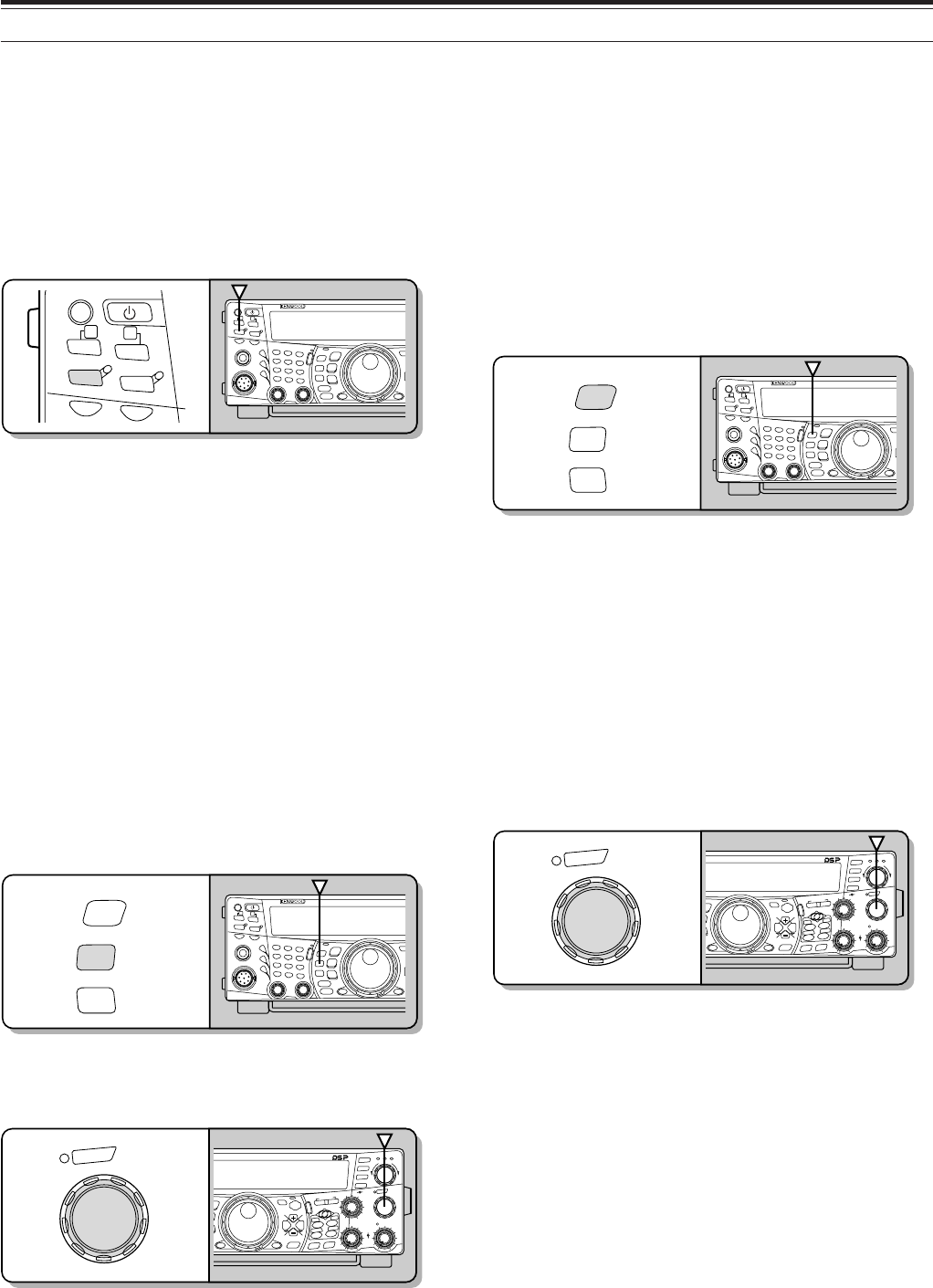
5 OPERATING BASICS
20
TRANSMITTING
For voice communications, press [SEND] or press
and hold Mic [PTT], then speak into the microphone
in your normal tone of voice. When you finish
speaking, press [SEND] again or release Mic [PTT].
To transmit CW, press [VOX/ LEVEL] to switch the
Break-in function ON, then close the key or keyer
paddle. Connect a key or keyer paddle {pages 3, 39},
then select CW mode.
PF
F LOCK A
SEND AT
ANT1/2
PROC
LEVEL
VOX
ATT PRE
LEVEL
PF
F LOCK A
1
CH1/REC
2
CH2/REC
3
CH3/REC
4
TONE/SEL
5
METER
6
CTCSS/SEL
7
NB/LEVEL
8
AGC/OFF
9
FINE/STEP
.
DCS/SEL
0
SHIFT/OFFSET
ENT
SEND
PHONES
MIC
AT
ANT1/2
PROC
LEVEL
VOX
ATT PRE
LEVEL
LEVEL
LEVEL
MANUAL
LO/
WIDTH
HI/
SHIFT
N.R.
A.N.
B.C.
FUNC
CLR
MAIN
AUTO
CAR
TX MONI
DELAY NAR
REV
MIC
PWR
KEY
LSB
USB
CW
FSK
FM
AM
DISP
SEL
1MHz CTRL
ME
N
M
HF/VHE/UHF ALL M
O
For a detailed explanation on transmitting, see
“BASIC COMMUNICATIONS”, beginning on page 28.
Note: When using AM, CW, or FSK mode, you may adjust the
carrier level. In general, adjust the level so that the ALC meter reads
within the limits of the ALC zone. For the adjustment procedures,
refer to the instructions for each mode in “TRANSMISSION”
{pages 28, 29, 30}.
SELECTING TRANSMIT POWER
It is wise to select a lower transmit power if
communication is still reliable. This lowers the risk of
interfering with others on the band. When operating
from battery power, selecting a lower transmit power
allows you more operating time before a charge is
necessary. This transceiver allows you to change the
transmit power even while transmitting.
1Press [PWR/ TX MONI].
• The current transmit power appears.
CAR
MIC
TX MONI
PWR
DELAY
KEY
PF
F LOCK A
1
CH1/REC
2
CH2/REC
3
CH3/REC
4
TONE/SEL
5
METER
6
CTCSS/SEL
7
NB/LEVEL
8
AGC/OFF
9
FINE/STEP
.
DCS/SEL
0
SHIFT/OFFSET
ENT
SEND
PHONES
MIC
AT
ANT1/2
PROC
LEVEL
VOX
ATTPRE
LEVEL
LEVEL
LEVEL
MANUAL
LO/
WIDTH
HI/
SHIFT
N.R.
A.N.
B.C.
FUNC
CLR
MAIN
AUTO
CAR
TX MONI
DELAY NAR
REV
MIC
PWR
KEY
LSB
USB
CW
FSK
FM
AM
DISP
SEL
1MHz CTRL
ME
N
M
HF/VHE/UHF ALL M
O
2Turn the MULTI/ CH control counterclockwise to
reduce the power or clockwise to increase the
power.
CH
MULTI
CALL
C.IN
U
TO
S
B
S
B
SUB
S
EL
1MHz CTRL
MR
M VFO
MG.SEL
M.IN
M.IN
QUICK MEMO
SATL
A/B
M/S REV
TRACE
MAIN
MANUAL
RF
AF
SQL
SUB
CH
MULTI
BCMAIN
GAIN
VFO/CH
VFO/M A=B
SPLIT
MENU TF-
SET
MAIN SUB
SG.SEL
SCAN
RIT
CW TUNE 9.6k STA
RIT/SUB
CON
XIT
ALT
SET
CLEAR
P. C . T
_+
HF/VHE/UHF ALL MODE MULTI BANDER TS-2000
• The selectable range differs, depending on the
current band and mode.
3Press [PWR/ TX MONI] to complete the setting.
Note: You may access Menu No. 23, “FINE TRANSMIT POWER
TUNING”, and select “ON” (press [+]) to change the step size from
5 W to 1 W {page 79}.
MICROPHONE GAIN
The microphone gain must be adjusted when SSB
or AM mode is used without speech processing
{pages 28, 29}.
1Press [MIC/ CAR].
• The current microphone gain level appears.
The default is 50; the range is from 0 to 100.
CAR
TX MONI
DELAY
MIC
PWR
KEY
PF
FLOCK A
1
CH1/REC
2
CH2/REC
3
CH3/REC
4
TONE/SEL
5
METER
6
CTCSS/SEL
7
NB/LEVEL
8
AGC/OFF
9
FINE/STEP
.
DCS/SEL
0
SHIFT/OFFSET
ENT
SEND
PHONES
MIC
AT
ANT1/2
PROC
LEVEL
VOX
ATTPRE
LEVEL
LEVEL
LEVEL
MANUAL
LO/
WIDTH
HI/
SHIFT
N.R.
A.N.
B.C.
FUNC
CLR
MAIN
AUTO
CAR
TX MONI
DELAY NAR
REV
MIC
PWR
KEY
LSB
USB
CW
FSK
FM
AM
DISP
SEL
1MHz CTRL
ME
N
M
HF/VHE/UHF ALL M
O
2Press [SEND] or press and hold Mic [PTT].
• The MAIN band LED lights red.
3SSB: While speaking into the microphone, adjust
the MULTI/ CH control so that the ALC meter
reflects your voice level, but does not exceed the
ALC limit.
AM: While speaking into the microphone, adjust
the MULTI/ CH control so that the calibrated
power meter slightly reflects your voice level.
CW, FSK: While transmitting, adjust the
MULTI/ CH control so that the ALC meter reflects
the carrier level within the ALC zone.
CH
MULTI
CALL
C.IN
U
TO
S
B
S
B
SUB
S
EL
1MHz CTRL
MR
M VFO
MG.SEL
M.IN
M.IN
QUICK MEMO
SATL
A/B
M/S REV
TRACE
MAIN
MANUAL
RF
AF
SQL
SUB
CH
MULTI
BCMAIN
GAIN
VFO/CH
VFO/M A=B
SPLIT
MENU TF-
SET
MAIN SUB
SG.SEL
SCAN
RIT
CW TUNE 9.6k STA
RIT/SUB
CON
XIT
ALT
SET
CLEAR
P. C . T
_+
HF/VHE/UHF ALL MODE MULTI BANDER TS-2000
4Press [SEND] or release Mic [PTT].
• The MAIN band LED lights green or turns off,
depending on the MAIN SQL control setting.
5Press [MIC/ CAR].
For FM mode, access Menu No. 41 {page 28} and
select “LOW”, “MID”, or “HIGH” for the microphone
gain.
Note: When using the optional MC-90 microphone in FM mode,
select “HIGH” for the microphone gain. The microphone sensitivity is
low in FM mode. This may cause insufficient modulation. For other
microphones, select either “LOW” or “MID”.
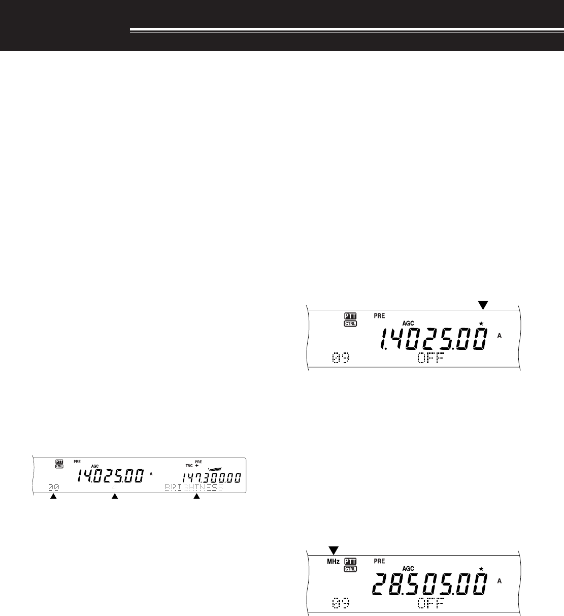
21
MENU SETUP
WHAT IS A MENU?
Many functions on this transceiver are selected or
configured via a software-controlled Menu, rather
than through the physical controls of the transceiver.
Once familiar with the Menu system, you will
appreciate the versatility it offers. You can customize
the various timings, settings, and programming
functions on this transceiver to meet your needs
without using many controls and switches.
MENU A/ MENU B
This transceiver has two menus: Menu A and
Menu B. These menus contain identical functions
and can be configured independently. The
transceiver, therefore, allows you to switch between
two different environments quickly and easily. For
example, you can configure Menu A for DXing and
contesting while Menu B is for the relaxed local
ragchewing. By switching from Menu A to Menu B,
you can instantly change the Menu configuration and
key assignment to suit your current operating style.
Or, two operators may share a single transceiver by
dedicating one Menu to each operator. Both
operators can always enjoy their own configuration.
MENU ACCESS
1Press [MENU].
• The Menu No. and setting appear on the main
dot-matrix display, and the explanation of the
menu appears on the sub dot-matrix display.
2Press [A/B] to select Menu A or Menu B.
• “A” or “B” appears, indicating which Menu is
selected.
3Turn the MULTI/ CH control to select the desired
Menu No.
• Each time you change the Menu No.,
a different scrolling message appears on the
sub dot-matrix display, describing the Menu
No.
• You will see “PUSH SUB” if there are sub-
menus in the Menu No. Pressing [SUB] allows
you to select from among the sub-menus.
Press [MAIN] to exit the sub-menu selection.
4Press [+], [–], Mic [UP]/ [DWN] to select a
parameter.
5Press [MENU] to exit Menu mode.
QUICK MENU
Because the number of functions this transceiver
provides is extraordinary, there are numerous items in
each Menu. If you find accessing desired Menu Nos.
to be too time consuming, use the Quick Menu to
create your own customized, abbreviated Menu. You
can then add those Menu Nos. which you frequently
use, to the Quick Menu. Copying Menu Nos. to the
Quick Menu has no effect on the Menu.
PROGRAMMING THE QUICK MENU
1Press [MENU].
2Turn the MULTI/ CH control to select the desired
Menu No.
3Press QUICK MEMO [M.IN].
• A star appears, indicating that the Menu item
has been added to the Quick Menu.
• To remove the item from the Quick Menu,
press QUICK MEMO [M.IN] again.
4Press [MENU] to exit Menu mode.
Note: You cannot add a sub menu No. to the Quick Menu. Press
[MAIN] to go back to the main menu No., then press
QUICK MEMO [M.IN] to add the menu No. to the Quick Menu.
USING THE QUICK MENU
1Press [MENU].
2Press [1MHz/ SEL].
• “MHz” appears.
3Turn the MULTI/ CH control to select the desired
Quick Menu No.
4Press [+], [–], Mic [UP]/[DWN] to change the
current setting for the selected Menu No.
5Press [MENU] to exit Quick Menu mode.
Note: If the Quick Menu has not been programmed, turning the
MULTI/ CH control in step 2 causes “CHECK” to be output in Morse
code.

22
6 MENU SETUP
MENU CONFIGURATION
puorG
uneM .oN
noitcnuF snoitceleS tluafeD .feR gaPe
rotarepO ecafretnI
00 ssenthgirbyalpsiD mumixam:4,muminim:1,FFO 4ot1/FFO357
10noitanimulliyeKFFO/NONO57
gninuT lortnoC
20noituloverrepegnahclortnocgninuT0001/005000183
30htiwgninuT HC/ITLUM lortnocFFO/NONO73
40 gnisuybdegnahcseicneuqerfOFVffosdnuoReht HC/ITLUM lortnoc FFO/NONO73
50 ehtrofezispetsycneuqerfzHk9 HC/ITLUM dnabtsacdaorbMAehtnoedomMAnilortnoc FFO/NO
eeS ecnerefeR egaP
73
yromeM lennahC
60lennahCyromeM sseccaotBUSsserP unem-buseht ––
A60noitarepotilpsOFV-yromeMFFO/NOFFO06
B60 lennahcyromem)FFO(dexifro)NO(elbanuT seicneuqerf FFO/NOFFO06
nacS noitarepO
70dewolsyllaitrapnacsmargorPFFO/NONO76
80 margorPehtrofegnarycneuqerfnwodwolS nacs /004/003/002/001 zH005 zH00376
90dlohnacsmargorPFFO/NOFFO86
01dohtememusernacS OT
)detarepO-emiT(
/
OC
)detarepO-reirraC(
OT86
11egnarnacslausiV 181/19/16/13 slennahc 16
slennahc
07
rotinoM dnuoS
21 leveltuptuopeeB mumixam:9,muminim:1,FFO 9ot1/FFO447
31 emulovenotedisXT mumixam:9,muminim:1,FFO 9ot1/FFO544
41 emulovkcabyalpA3-URD mumixam:9,muminim:1,FFO 9ot1/FFO498
51 emulovkcabyalp3-SV mumixam:9,muminim:1,FFO 9ot1/FFO419
rekaepS tuptuO
61
ro2PS.TXErofnoitarugifnoctuptuooiduA enohpdaeh
2/1/0087
0xiMbuS/niaM:)L(1PS xiMbuS/niaM:)R(2PS
1niaM:)L(1PS buS:)R(2PS
2xiMbuS4/1+niaM:)L(1PS xiMniaM4/1+buS:)R(2PS
71 eht(2PS.TXEdna1PS.TXEehtsesreveR stuptuooidua)slennahcR/Lkcajenohpdaeh FFO/NOFFO87

23
6 MENU SETUP
puorG
uneM .oN
noitcnuF snoitceleS tluafeD .feR egaP
annetnAXR81rotcennocTNAXRFHehtmorftupninaelbanEFFO/NOFFO67
retem-S hcleuqS
91hcleuqsretem-S sseccaotBUSsserP unem-buseht ––
A91hcleuqsretem-SelbanEFFO/NOFFO87
B91hcleuqsretem-SrofemitgnaH 005/052/521/FFO sm FFO87
PSD rezilauqE
02
rezilauqeXRPSD
F/TSOOBH/FFO /TSOOBB/SSAP RESU/NEVNOC FFO ,87 401
:FFOtalF
:TSOOBHtsoobhgiH
:SSAPFssaptnamroF
:TSOOBBtsoobssaB
:NEVNOClanoitnevnoC
:RESU)erawtfosPCRArofdevreseR(talF
12
rezilauqeXTPSD
F/TSOOBH/FFO /TSOOBB/SSAP RESU/NEVNOC FFO ,14 401
:FFOtalF
:TSOOBHtsoobhgiH
:SSAPFssaptnamroF
:TSOOBBtsoobssaB
:NEVNOClanoitnevnoC
:RESU)erawtfosPCRArofdevreseR(talF
retliFPSD22MAroBSSrofhtdiwdnabretlifXTPSD /8.2/6.2/4.2/2.2/0.2 zHk0.3
zHk4.2
14
gninuTeniF32gninutrewoptimsnarteniFFFO/NOFFO83
TOT42remittuo-emiT 03/02/01/5/3/FFO setunim FFO87
retrevsnarT52yalpsidycneuqerfretrevsnarTNO/FFOFFO97
annetnA renuT
62gninutehtsetelpmocTAnehwdlohXTNO/FFOFFO37
72gniviecerelihwTAenil-nINO/FFOFFO37
raeniL reifilpmA
82lortnocreifilpmaraeniL sseccaotBUSsserP unem-buseht ––
A82dnabFHrofyaledlortnocreifilpmaraeniL2/1/FFOFFO67
B82dnabzHM05rofyaledlortnocreifilpmaraeniL2/1/FFOFFO67
C82dnabzHM441rofyaledlortnocreifilpmaraeniL2/1/FFOFFO67
D82 zHM044/034rofyaledlortnocreifilpmaraeniL dnab 2/1/FFOFFO67
E82dnabzHG2.1rofyaledlortnocreifilpmaraeniL2/1/FFOFFO67
egasseM kcabyalP
92kcabyalpegassemWCdnaecioV sseccaotBUSsserP unem-buseht ––
A92kcabyalpehttaepeRNO/FFOFFO ,4409
B92kcabyalpehtgnitaeperrofemitlavretnI sdnoces06ot0 )dnoces1fospetsni( .ces01 ,4409

24
6 MENU SETUP
puorG
uneM .oN
noitcnuF snoitceleS tluafeD .feR egaP
WC
03kcabyalprevoytiroirpgniyeKNO/FFOFFO44
13ycneuqerfenotedisXT/hctipXRWC zH0001ot004 )zH05fospetsni( zH00803
23emitesirWCsm6/4/2/1sm677
33oitarthgiewhsad,todgniyekWC 0.4ot5.2/OTUA )1.0fospetsni( OTUA24
43oitarthgiewotuagniyekWCesreveRNO/FFOFFO24
53edomyekguBNO/FFOFFO34
63edomBSSniXTWCotuANO/FFOFFO44
73WCotBSSgnignahcrofnoitcerrocycneuqerFNO/FFOFFO44
KSF
83tfihsKSF
zH058/524/002/071
zH07115
93ytiralopgniyekKSFSREVNI/LAMRON
LAMRON
15
04ycneuqerfenotKSFzH5212/5721
zH5212
15
MF
14MFrofniagciMHGIH/DIM/WOLWOL02
24MFrofedomenot-buSTNOC/TSRUB
eeS ecnerefer egap
33
34tesfforetaeperotuANO/FFONO43
44enotzH0571:dlohXTNO/FFOFFO33
FMTD
54snoitcnufFMTD sseccaotBUSsserP unem-buseht ––
A54tcelesyromemrebmunFMTD sseccaotBUSsserP unem-buseht ––
B54rebmunFMTDderotsrofdeepsXTTSAF/WOLSTSAF67
C54rebmunFMTDderotsrofnoitarudesuaP /057/005/052/001 sm0002/0051/0001 sm00567
D54lortnocetomerciMelbanENO/FFOFFO18
CNT
64CNTlanretnI:dnabBUS/NIAMBUS/NIAMBUS05
74CNTlanretnI:deepsrefsnartataDspb0069/0021
spb0021
05
84dnabgnisnesDCD /DNABCNT BUS&NIAM CNT dnab 05
94edom)enuTretsulCtekcaP(.T.C.P sseccaotBUSsserP unem-buseht ––
A94edomenuTretsulCtekcaPOTUA/LAUNAM
LAUNAM
35
B94enotnoitamrifnocXRretsulCtekcaPECIOV/ESROM/FFO
ESROM
35
05noitarugifnoctekcaP sseccaotBUSsserP unem-buseht ––
A05htdiwdnabretliftekcaPNO/FFOFFO05
B05tekcaProfleveltupniFA)1fospetsni(9ot0405
C05noitarepotekcaprofleveltuptuoFAdnabNIAM)1fospetsni(9ot0405
D05noitarepotekcaprofleveltuptuoFAdnabBUS)1fospetsni(9ot0405
E05CNTlanretxE:dnabBUS/NIAMBUS/NIAMNIAM05
F05CNTlanretxE:deepsrefsnartataDspb0069/0021
spb0021
05

25
6 MENU SETUP
puorG
uneM .oN
noitcnuF snoitceleS tluafeD .feR egaP
syekFP
15tnemngissayekFP sseccaotBUSsserP unem-buseht ––
A15yekFPlenaptnorF
/.R.N/.C.B/.N.A/FFO /zHM1/2/1TNA/BN /RLC/LLAC/LRTC /2HC/3HC/ENIF /ENUTWC/1HC /OFVM/NI.M /M/OFV/B=A/NACS /TILPS/TES-FT/B/A PSD/RMQ/NI.MQ /INOMXR/INOM /1ECIOV/2ECIOV 26-00UNEM
1ECIOV77
B15yek)LLAC(1FPenohporciMA15saemaSB/A77
C15yek)OFV(2FPenohporciMA15saemaSTILPS77
D15yek)RM(3FPenohporciMA15saemaS
M/OFV
77
E15yek)FP(4FPenohporciMA15saemaS XR INOM 77
evalS/retsaM noitarepo
25 evals/retsamnirefsnartycneuqerftilpS noitarepo NO/FFOFFO08
35 seicneuqerftilpSderrefsnartehtetirwottimreP sOFVtegratehtot NO/FFOFFO08
tibihnIXT45tibihniXTNO/FFOFFO14
tekcaP
55edomnoitacinummoctekcaPNO/FFOFFO94
65deepsnoitacinummoctropMOC /00291/0069/0084 spb00675/00483 0069 spb 05
OPA75noitcnuf)ffOrewoPotuA(OPA 081/021/06/FFO setunim FFO27
0002-CR noitarugifnoC
85edomnoitarepoysaenitnof0002-CR2TNOF/1TNOF1TNOF89
95 yalpsidxirtam-tod)X(0002-ST/lenap0002-CR tsartnoc )1fospetsni(61ot1857
060002-CRrofedomyalpsiD /EVITAGEN EVITISOP
EVITISOP
89
0002-ST retaepeR snoitcnuF )ylnOepyt-K(
16noitcnufretaepeR sseccaotBUSsserP unem-buseht ––
A16tcelesedomretaepeR /DEKCOL/FFO SSORC FFO88
B16dlohXTretaepeRNO/FFOFFO88
C16edocDIlortnocetomeR999ot00000028
D16 etomerlanretxenilangistnemegdelwonkcA edomlortnoc NO/FFOFFO28
E16lortnocetomerlanretxENO/FFOFFO28

26
6 MENU SETUP
noitcnuF uneM .oN
RETLIFPSD
rezilauqeXRPSD02
rezilauqeXTPSD12
MAroBSSrofhtdiwdnabretlifXTPSD22
FMTD
tcelesyromemrebmunFMTDA54
rebmunFMTDderotsrofnoitarudesuaPC54
rebmunFMTDderotsrofdeepsXTB54
MF
tesfforetaeperotuA34
edomMFrofhcleuqsretem-SelbanEA91
hcleuqsretem-SrofemitgnaHB91
MFrofniagciM14
MFrofedomenot-buS24
enotzH0571:dlohXT44
KSF
ytiralopgniyekKSF93
tfihsKSF83
ycneuqerfenotKSF04
DCL
ssenthgirbyalpsiD00
noitanimulliyeK10
xirtam-tod)X(0002-ST/lenap0002-CR tsartnocyalpsid 95
NOITCNUFYROMEM
noitarepotilpsOFV-yromeMA60
lennahcyromem)FFO(dexifro)NO(elbanuT seicneuqerf B60
noitcnuF uneM .oN
REIFILPMA
dnabFHrofyaledlortnocreifilpmaraeniLA82
dnabzHM05rofyaledlortnocreifilpmaraeniLB82
zHM441rofyaledlortnocreifilpmaraeniL dnab C82
rofyaledlortnocreifilpmaraeniL dnabzHM044/034 D82
dnabzHG2.1rofyalerlortnocreifilpmaraeniLE82
ANNETNA
TNAXRFHehtmorftupninaelbanE rotcennoc 81
RENUTANNETNA
gniviecerelihwTAenil-nI72
gninutehtsetelpmocTAnehwdlohXT62
NOITCNUFPEEB
leveltuptuopeeB21
WC
edomBSSniXTWCotuA63
edomyekguB53
oitarthgiewhsad,todgniyekWC33
emitesirWC23
ycneuqerfenotedisXT/hctipXRWC13
otBSSgnignahcrofnoitcerrocycneuqerFWC 73
kcabyalprevoytiroirpgniyeK03
oitarthgiewotuagniyekWCesreveR43
REFSNARTATAD
tilpSderrefsnartehtetirwottimreP .sOFVtegratehtotseicneuqerf 35
evals/retsamnirefsnartycneuqerftilpS noitarepo 25
puorG
uneM .oN
noitcnuF snoitceleS tluafeD .feR egaP
ykS +IIdnammoC )ylnOepyt-K(
26noitarugifnoc+IIdnammoCykS sseccaotBUSsserP unem-buseht ––
A26+IIdnammoCykSrofngisllacrednammoC ehtrofngisllacatupnI rednammoC ON LLAC 38
B26+IIdnammoCykSrofngisllacretropsnarT ehtrofngisllacatupnI retropsnarT ON LLAC 38
C26ycneuqerfenot+IIdnammoCykSsenotSSCTC83
zH5.88
38
D26deepsnoitacinummoc+IIdnammoCykSspb0069/0021 0021 spb 38
E26edom+IIdnammoCykS /TNEILC/FFO /DNAMMOC RETROP-T FFO38
ALPHABETICAL FUNCTION LIST

27
6 MENU SETUP
noitcnuF uneM .oN
CNT
tekcaProfleveltupniFAB05
deepsnoitacinummoctropMOC65
CNTlanretxE:deepsrefsnartataDF05
CNTlanretnI:deepsrefsnartataD74
dnabgnisnesDCD84
tekcaprofleveltuptuoFAdnabniaM noitarepo C05
CNTlanretxE:dnabBUS/NIAME05
CNTlanretnI:dnabBUS/NIAM64
edomnoitacinummoctekcaP55
htdiwdnabretliftekcaPA05
enotnoitamrifnocXRretsulCtekcaPB94
edomenuTretsulCtekcaPA94
noitarepotekcaprofleveltuptuoFAdnabbuSD05
LORTNOCNOISSIMSNART
remiTtuo-emiT42
tibihniXT45
RETREVSNART
yalpsidycneuqerfretrevsnarT52
LORTNOCGNINUT
otBSSgnignahcrofnoitcerrocycneuqerFWC 73
ehtrofezispetsycneuqerfzHk9 HC/ITLUM tsacdaorbMAehtnoedomMAnilortnoc dnab 50
ybdegnahcseicneuqerfOFVffosdnuoR ehtgnisu HC/ITLUM lortnoc 40
noituloverrepegnahclortnocgninuT20
htiwgninuT HC/ITLUM lortnoc30
LORTNOCEMULOV
leveltuptuopeeB21
emulovkcabyalpA3-URD41
emulovenotedisXT31
emulovkcabyalp3-SV51
noitcnuF uneM .oN
KCABYALPEGASSEM
kcabyalpehtgnitaeperrofemitlavretnIB92
kcabyalpehttaepeRA92
SYEKFP
yekFPlenaptnorFA15
yek)LLAC(1FPenohporciMB15
yek)OFV(2FPenohporciMC15
yek)RM(3FPenohporciMD15
yek)FP(4FPenohporciME15
LORTNOCREWOP
gninutrewoptimsnarteniF32
FFO/NOREWOP
noitcnuf)ffOrewoPotuA(OPA75
LORTNOCETOMER
lortnocetomerciMelbanED54
0002-CRrofedomyalpsiD06
edomnoitarepoysaenitnof0002-CR85
xirtam-tod)X(0002-ST/lenap0002-CR tsartnocyalpsid 95
RETAEPER
etomerlanretxenilangistnemegdelwonkcA edomlortnoc D16
lortnocetomerlanretxEE16
edocDIlortnocetomeRC16
tcelesedomretaepeRA16
dlohXTretaepeRB16
NACS
dlohnacsmargorP90
dewolsyllaitrapnacsmargorP70
margorPehtrofegnarycneuqerfnwodwolS nacs 80
dohtememusernacS01
egnarnacslausiV11
+IIDNAMMOCYKS
+IIdnammoCykSrofngisllacrednammoCA26
deepsnoitacinummoc+IIdnammoCykSD26
edom+IIdnammoCykSE26
ycneuqerfenot+IIdnammoCykSC26
+IIdnammoCykSrofngisllacretropsnarTB26
REKAEPS
ro2PS.TXErofnoitarugifnoctuptuooiduA enohpdaeh 61
eht(2PS.TXEdna1PS.TXEehtsesreveR stuptuooidua)slennahcR/Lkcajenohpdaeh 71
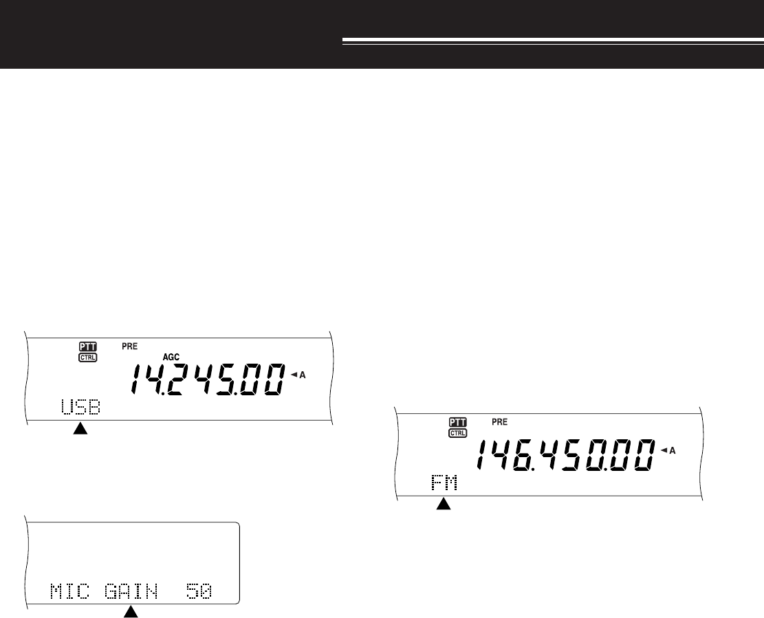
28
BASIC COMMUNICATIONS
SSB TRANSMISSION
SSB is the most commonly-used mode on the HF
Amateur bands. Compared with other voice modes,
SSB requires only a narrow bandwidth for
communications. SSB also allows long distance
communications with minimum transmit power.
If necessary, refer to “OPERATING BASICS”,
beginning on page 18, for details on how to receive.
1Select an operating frequency.
2Press [LSB/ USB/ AUTO] to select either lower or
upper sideband mode.
• “LSB” or “USB” appears to show which
sideband is selected.
3Press [MIC/ CAR] to activate the Microphone
Gain Adjust.
• The current gain level appears.
4Press [SEND], or press and hold Mic [PTT].
• The MAIN band LED lights red.
• Refer to “VOX” {page 39} for information on
automatic TX/RX switching.
5Speak into the microphone and adjust the
MULTI/ CH control so that the ALC meter reflects
your voice level but does not exceed the ALC limit.
• Speak in your normal tone and level of voice.
Speaking too close to the microphone or too
loudly may increase distortion and reduce
intelligibility at the receiving end.
• You may want to use the Speech Processor.
Refer to “SPEECH PROCESSOR” {page 40}
for details.
6Press [SEND] or release Mic [PTT] to return to
receive mode.
• The MAIN band LED lights green or turns off,
depending on the MAIN SQL setting.
7Press [MIC/ CAR] to quit the Microphone Gain
Adjust.
Refer to “COMMUNICATING AIDS”, beginning on
page 37, for information on additional useful
operation functions.
FM TRANSMISSION
FM is a common mode for communicating on VHF or
UHF frequencies. Many amateur radio operators use
their portable radios and mobile transceivers in FM
mode. You can also utilize repeaters to reach your
friends when they are outside your antenna
coverage. Although FM requires a wider bandwidth
when compared to SSB or AM mode, it has the finest
audio quality among these modes. When combined
with the full-quieting aspect of FM signals, which
suppress background noise on the frequency, FM can
be the best method for maintaining regular schedules
with your local friends.
If necessary, refer to “OPERATING BASICS”,
beginning on page 18, for details on how to receive.
1Select an operating frequency.
2Press [FM/ AM/ NAR] to select FM mode.
• “FM” appears.
3Press [SEND], or press and hold Mic [PTT].
• The MAIN band LED lights red.
• Refer to “VOX” {page 39} for information on
automatic TX/RX switching.
4Speak into the microphone in your normal tone
and level of voice.
• Speaking too close to the microphone or too
loudly may increase distortion and reduce
intelligibility at the receiving end.
• You can switch the Microphone Gain for FM
between “LOW”, “MID”, and “HIGH” by using
Menu No. 41. “LOW” is usually appropriate;
however, select high if other stations report that
your modulation is weak. The MULTI/ CH
control has no effect in FM mode.
5Press [SEND] or release Mic [PTT] to return to
receive mode.
• The MAIN band LED lights green or turns off,
depending on the MAIN SQL setting.
Refer to “COMMUNICATING AIDS”, beginning on
page 37, for additional information on useful
operation functions.
Note: Microphone gain adjustment for SSB or AM has no effect in
FM mode. In FM mode, you must select “LOW”, “MID” or “HIGH” in
Menu No. 41.
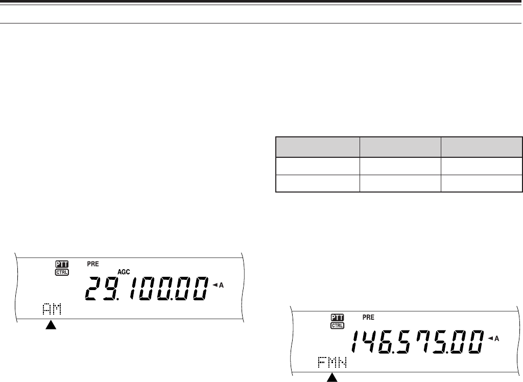
29
7 BASIC COMMUNICATIONS
AM TRANSMISSION
Each mode used on the HF Amateur bands has its
own advantages. Although long distance DX
contacts may be less common while using AM, the
superior audio quality characteristic of AM operation
is one reason why some hams prefer this mode.
When looking for others operating on AM, check the
following frequencies first:
3885 kHz, 7290 kHz, 14286 kHz, 21390 kHz, and
29000 ~ 29200 kHz
If necessary, refer to “OPERATING BASICS”,
beginning on page 18, for details on how to receive.
1Select an operating frequency.
2Press [FM/ AM/ NAR] to select AM mode.
• “AM” appears.
3Press [MIC/ CAR] to activate the Microphone
Gain Adjust.
• The current gain level appears.
4Press [SEND], or press and hold Mic [PTT].
• The MAIN band LED lights red.
• Refer to “VOX” {page 39} for information on
automatic TX/RX switching.
5Speak into the microphone and adjust the
MULTI/ CH control so that the calibrated power
meter slightly reflects your voice level.
• Speak in your normal tone and level of voice.
Speaking too close to the microphone or too
loudly may increase distortion and reduce
intelligibility at the receiving end.
• You may want to use the Speech Processor.
Refer to “SPEECH PROCESSOR” {page 40}
for details.
6Press [SEND] or release Mic [PTT] to return to
receive mode.
• The MAIN band LED lights green or turns off,
depending on the MAIN SQL setting.
7Press [MIC/ CAR] to quit the Microphone Gain
Adjust.
Refer to “COMMUNICATING AIDS”, beginning on
page 37, for information on additional useful
operation functions.
Note: If necessary, adjust the carrier level before speaking into the
microphone. Press [FUNC], [MIC/ CAR] to enter the adjustment
mode. While transmitting only carrier signals, turn the MULTI/ CH
control so that the ALC meter just begins to indicate. Press [FUNC],
[MIC/ CAR] again to complete the adjustment.
NARROW BANDWIDTH FOR FM
When operating in FM mode, you can select wide or
narrow bandwidth operation. The table below shows
the RX IF filter bandwidth and TX deviation
combination for each operating mode. The
bandwidth selection is crucial to avoid audio distortion
or insufficient intelligibility that the other station will
encounter.
edoM retliFFIXR noitaiveDXT
MFediWediW
NMFworraN
1
worraN
1K-type: Main transceiver only.
All E-types: Main transceiver and sub-receiver.
1Press [FM/ AM/ NAR] to select FM mode.
2Press [FUNC], [FM/ AM/ NAR] to toggle the
selection between Wide and Narrow.
• “FM” or “FMN” appears to indicate which
bandwidth is selected.
NARROW BANDWIDTH FOR AM
When receiving AM on the main transceiver, you can
further decrease the bandwidth to eliminate
interference. However, the TX deviation of AM is not
affected by this selection.
1Press [FM/ AM/ NAR] to select AM mode on the
main transceiver.
2Press [FUNC], [FM/ AM/ NAR] to toggle the
selection between Normal and Narrow.
• “AM” or “AMN” appears to indicate which IF
bandwidth is selected for the main transceiver.
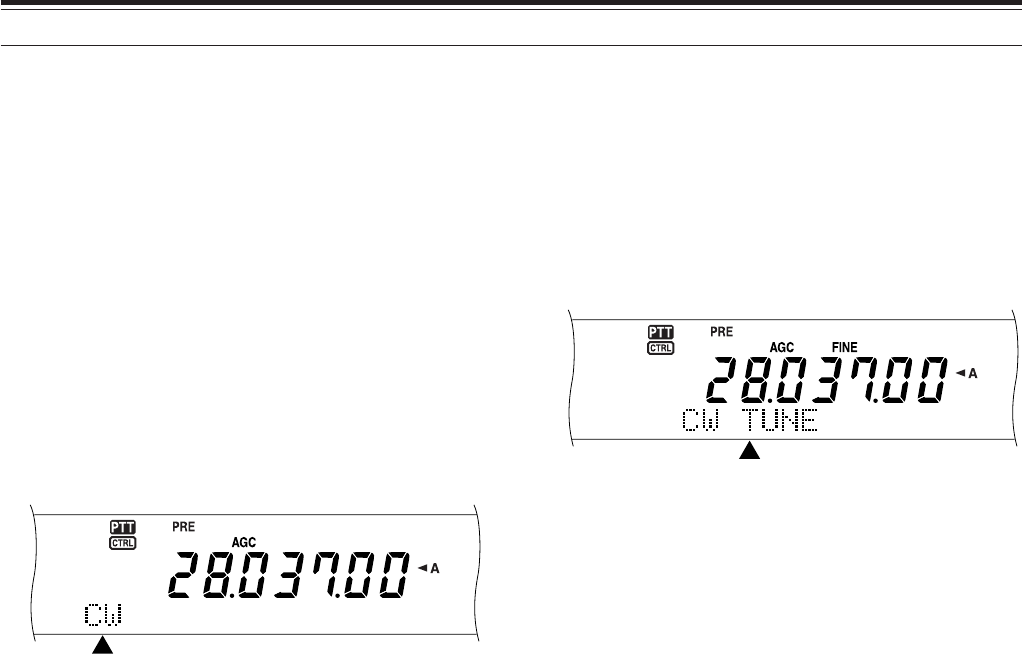
7 BASIC COMMUNICATIONS
30
CW TRANSMISSION
CW operators know that this mode is very reliable
when communicating under worst conditions. It may
be true that newer digital modes rival CW as being
equally as useful in poor conditions. These modes,
however, do not have the long history of service nor
the simplicity that CW provides.
This transceiver has a built-in electronic keyer that
supports a variety of functions. For details on using
these functions, refer to “ELECTRONIC KEYER”
{page 42}.
If necessary, refer to “OPERATING BASICS”,
beginning on page 18, for details on how to receive.
1Select the operating frequency.
2Press [CW/ FSK/ REV] to select CW mode.
• “CW” appears.
• To precisely tune in another station, use Auto
Zero-beat. Refer to “AUTO ZERO-BEAT”
{below}.
3Press [SEND].
• The MAIN band LED lights red.
• Refer to “CW BREAK-IN” {page 42} for
information on automatic TX/ RX switching.
4Begin sending.
• As you transmit, you should hear a sidetone
that lets you monitor your own transmission.
Refer to “TX SIDETONE/ RX PITCH
FREQUENCY” {below}.
5Press [SEND] to return to receive mode.
• The MAIN band LED lights green or turns off,
depending on the MAIN SQL setting.
Note: You may adjust the carrier level when necessary. Press
[FUNC], [MIC/ CAR] to enter the adjustment mode. With the key
down, turn the MULTI/ CH control so that the ALC meter reads within
the ALC zone but does not exceed the upper ALC zone limit. Press
[FUNC], [MIC/ CAR] again to complete the adjustment.
AUTO ZERO-BEAT
Use Auto Zero-beat before transmitting to tune in a
CW station. Auto Zero-beat automatically and exactly
matches your transmit frequency with the station you
are receiving. Neglecting to do this will reduce your
chances of being heard by the other station.
1Press [FUNC], [RIT/ CW TUNE] to start Auto
Zero-beat.
• “CW TUNE” appears.
• Your transmit frequency automatically changes
so that the pitch of the received signal exactly
matches the TX sidetone/ RX pitch frequency
that you have selected. Refer to “TX
SIDETONE/ RX PITCH FREQUENCY” {below}.
• When matching is completed, “CW TUNE”
disappears.
• If matching is unsuccessful, the previous
frequency is restored.
2To quit Auto Zero-beat, press [FUNC],
[RIT/ CW TUNE] or [CLR].
Note:
◆
You cannot start Auto Zero-beat if you have selected 1.0 kHz or
wider for the DSP filter bandwidth.
◆
When using Auto Zero-beat, the matching error is within
±
50 Hz
in most cases.
◆
Auto Zero-beat may fail if the keying speed of the target station is
too slow or when some interference is present.
◆
When RIT function is ON, only RIT frequencies change to make
the Auto Zero-beat adjustment.
TX SIDETONE/ RX PITCH FREQUENCY
As you send CW, you will hear tones from the
transceiver speaker. These are called transmit (TX)
sidetones. Listening to these tones, you can monitor
what you are transmitting. You may also use the
tones to ensure that your key contacts are closing,
the keyer is functioning, or to practice sending without
actually putting a signal on the air.
Receive pitch refers to the frequency of CW that you
hear after tuning in a CW station.
On this transceiver, the frequency of the sidetone and
receive pitch are equal and selectable. Access Menu
No. 31 to select the frequency that is most
comfortable for you. The selectable range is from
400 Hz to 1000 Hz in steps of 50 Hz.
To change the volume of the TX sidetone, access
Menu No. 13. The selections range from 1 to 9 and
OFF.
Note: The position of the MAIN AF and SUB AF controls do not
affect the volume of the TX sidetone.

31
ENHANCED COMMUNICATIONS
SPLIT-FREQUENCY OPERATION
Usually you can communicate with other stations
using a single frequency for receiving and
transmitting. In this case, you select only one
frequency on either VFO A or VFO B. However, there
are cases where you must select one frequency for
receiving and a different frequency for transmitting.
This requires the use of two VFOs. This is referred to
as “split-frequency operation”. One typical case
which requires this type of operation is when you use
an FM repeater {page 32}. Another typical case is
when you call a rare DX station.
When a rare or desirable DX station is heard, that
operator may immediately get many simultaneous
responses. Often, such a station is lost under the
noise and confusion of many calling stations. If you
find that you are suddenly being called by many
operators, it is your responsibility to control the
situation. You may announce that you will be “listening
up 5 (kHz, from your present transmit frequency)”, or
“listening down between 5 and 10 (kHz)”.
1Press [MAIN], [A/B] to select VFO A or VFO B on
the main transceiver.
•“tA” or “tB” appears to show which VFO is
selected.
2Select an operating frequency.
• The frequency selected at this point will be
used for transmitting.
• To copy the selected VFO frequency to the
other VFO, press [A=B].
3Press [A/B] to select the other VFO.
4Select an operating frequency.
• The frequency selected on this VFO will be
used for receiving.
5Press [SPLIT].
• “SPLIT” appears.
• Each press of [A/B] reverses the receive and
transmit frequencies.
6To quit split-frequency operation, press [SPLIT]
again.
• “SPLIT” disappears.
If you access Menu No. 06A and select “ON”, you can
recall a memory channel to use for either receiving or
transmitting. For more information, refer to “Memory-
VFO Split Operation” {page 60} under “MEMORY
FEATURES”.
Note: You cannot perform SPLIT operation on the sub-receiver; it
has only one VFO.
TF-SET (TRANSMIT FREQUENCY SET)
TF-SET allows you to temporarily switch your transmit
frequency and receive frequency. Canceling this
function immediately restores the original transmit and
receive frequencies. By activating TF-SET, you can
listen on your transmit frequency, and change it while
listening. This allows you to check whether or not the
newly selected transmit frequency is free of
interference.
1Configure split-frequency operation as explained
in the previous section.
2Press and hold [TF-SET].
3While holding down [TF-SET], change the
operating frequency by turning the Tuning control
or by pressing Mic [UP]/ [DWN].
• The transceiver receives on the frequency that
you select, but the frequency shown on the
sub-display stays unchanged.
4Release [TF-SET].
• You are now receiving again on your original
receive frequency.
Successfully contacting a DX station in a pileup often
depends on making a well-timed call on a clear
frequency. That is, it is important to select a relatively
clear transmit frequency and to transmit at the exact
instant when the DX station is listening but the
majority of the groups aren’t transmitting. Switch
your receive and transmit frequencies by using TF-
SET and listen. You will soon learn the rhythm of the
DX station and the pileup. The more proficient you
become at using this function, the more DX stations
you will contact.
Note:
◆
If you press [FUNC], [ATT/ F LOCK] to lock the operating
frequency before using TF-SET, pressing an incorrect button by
mistake retains the original receive frequency.
◆
TF-SET is disabled while transmitting.
◆
If you have recalled a memory channel (excluding CH 290 to
299), you cannot change the recalled frequency using the
Tuning control.
◆
To enable the Tuning control, access Menu No. 06B and select
“ON”. Pressing Mic [UP]/ [DWN] after recalling a memory
channel changes the memory channels.
◆
An RIT frequency shift is not added; however, an XIT frequency
shift is added to the transmit frequency.
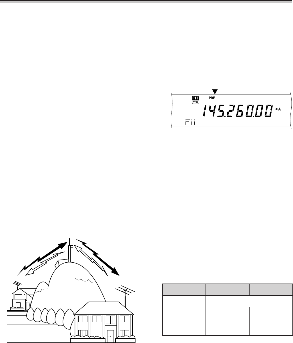
32
8 ENHANCED COMMUNICATIONS
FM REPEATER OPERATION
When using FM mode, you may access a repeater to
enjoy long distance communications. Repeaters,
which are often installed and maintained by radio
clubs, are usually located on mountain tops or other
elevated locations. Generally they operate at higher
ERP (Effective Radiated Power) than a typical
station. This combination of elevation and high ERP
allows communications in FM over much greater
distances than FM communications without using
repeaters.
Most repeaters use a receive and transmit frequency
pair with an offset. In addition, some repeaters must
receive a tone from the transceiver before it allows
access. Repeaters are available on the 29, 50, 144,
430/ 440 MHz, and 1.2 GHz bands (TS-2000/
TS-B2000 Optional). For further information,
including repeater frequencies, consult your local
repeater reference.
This transceiver provides the following three methods
for programming two separate frequencies:
• Using the Split-Frequency function {page 31}
• Programming an offset (29, 50, 144, 430/ 440 MHz
and 1.2 GHz bands)
• Storing in a Split-Frequency channel {page 59}
Note:
◆
When programming two separate frequencies using two VFOs,
be sure to select FM mode on both VFOs.
◆
When operating through a repeater, over deviation caused by
speaking too loudly into the microphone can cause your signal to
“talk-off” (break up) through the repeater.
PROGRAMMING AN OFFSET
When using the 29, 50, 144, 430/ 440 MHz or 1.2 GHz
band (TS-2000/ TS-B2000 Optional), selecting a single
frequency and an offset is another method for
programming two separate frequencies. Unlike the
Split-Frequency function, this method requires only a
single VFO.
Note: If you store offset settings in a memory channel, you need not
reprogram each time. Refer to “MEMORY FEATURES” {page 58}.
■Selecting an Offset Direction
1Select a receive frequency.
2Press [0/ SHIFT/OFFSET] to switch the offset
direction.
• Select whether the transmit frequency will
be higher (+) or lower (–) than the receive
frequency.
• “+” or “–” appears to indicate which offset
direction is selected.
• To program the –7.6 MHz (430 MHz) or
–6.0 MHz (1.2 GHz) offset on all E-types,
repeatedly press [0/ SHIFT/OFFSET] until
“=” appears.
If the offset transmit frequency falls outside the
allowable range, transmitting is inhibited. Use one
of the following methods to bring the transmit
frequency within the band limits:
• Move the receive frequency further inside the
band.
• Change the offset direction.
Note:
◆
You can only change the offset direction while in FM mode.
◆
While using an odd-split memory channel for transmitting,
you cannot change the offset direction.
■Selecting an Offset Frequency
To access a repeater which requires an odd-split
frequency pair, change the offset frequency from
the default which is used by most repeaters. The
default offset frequencies are as follows.
dnaB epyt-K sepyt-EllA
zHM441 ±zHk006
zHM044/034 ±zHM0.5 ±zHM6.1 zHM6.7–
zHG2.1 ±zHM0.21 ±zHM0.53 zHM0.6–
As for the 29 and 50 MHz bands, the default offset
is set to 0 MHz (Simplex). Program the desired
offset frequency for these bands.
1Press [FUNC], [0/ SHIFT/OFFSET].
2Turn the MULTI/ CH control to select the
appropriate offset frequency.
• The selectable range is from 0.00 MHz to
59.95 MHz in steps of 50 kHz.
3Press [FUNC], [0/ SHIFT/OFFSET] again to
complete the setting.
All E-types only: If you have selected “ =” for the offset
direction, you cannot change the default (–7.6 MHz or –6.0 MHz).
29.520 MHz
88.5 Hz
29.520 MHz
88.5 Hz
29.620 MHz
29.620 MHz
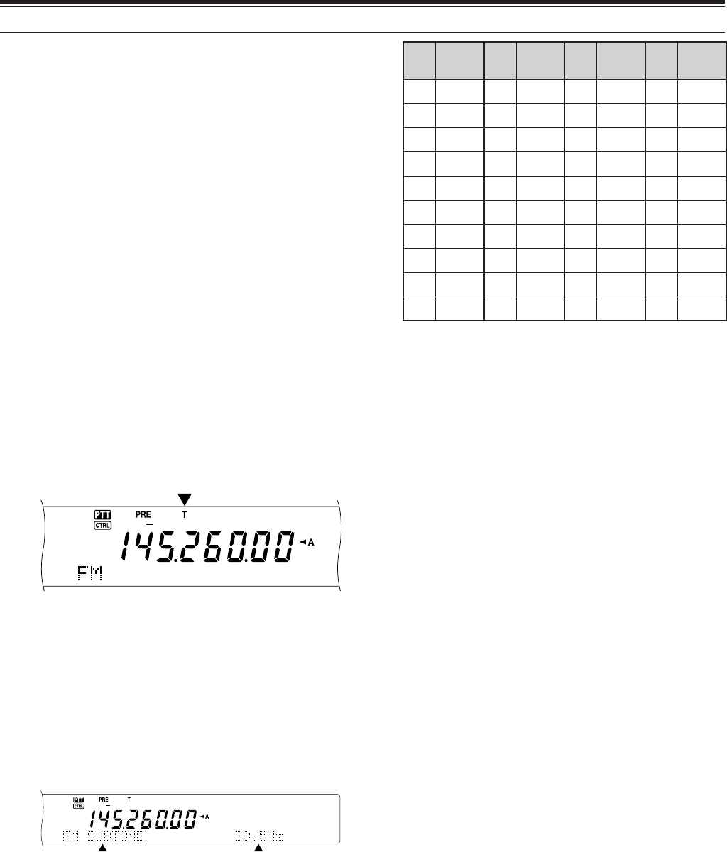
33
8 ENHANCED COMMUNICATIONS
TRANSMITTING A TONE
Some FM repeaters require the transceiver to
transmit a sub-audible tone to prevent other
repeaters on the same frequency from locking each
other up. The required tone frequency differs among
repeaters. Repeaters also differ in their requirements
for either continuous or burst tones. For the
appropriate selections for your accessible repeaters,
consult your local repeater reference.
After completing the tone settings, pressing [SEND]
or pressing and holding Mic [PTT] causes the
transceiver to transmit the selected tone. If you have
selected a 1750 Hz tone, press [4/ TONE/SEL] to
transmit the tone without pressing Mic [PTT].
Note: If you store tone settings in a memory channel, you need not
reprogram each time. Refer to “MEMORY FEATURES” {page 58}.
■Activating the Tone Function
1Confirm that FM mode has been selected on
the VFO(s).
• When using two VFOs, you must select FM
mode on both VFOs.
2Press [4/ TONE/SEL] to switch the Tone
function ON (or OFF).
• “T” appears when the function is ON.
Note:
◆
You cannot use the Tone function with the CTCSS or DCS
functions.
◆
You need to activate the Tone function only when selecting
one of the 38 standard frequencies. The selection you make
here will not affect the transmission of the 1750 Hz tone.
■Selecting a Tone Frequency
1Press [FUNC], [4/ TONE/SEL].
• The current tone frequency appears. The
default is 88.5 Hz.
2Turn the MULTI/ CH control to select the
appropriate tone frequency.
• The available tone frequencies are listed in
the following table.
3Press [FUNC], [4/ TONE/SEL] to complete the
setting.
.oN .qerF )zH( .oN .qerF )zH( .oN .qerF )zH( .oN .qerF )zH(
100.76114.79125.631138.291
209.17210.001223.141235.302
304.47315.301322.641337.012
400.77412.701424.151431.812
507.97519.011527.651537.522
605.28618.411622.261636.332
704.58718.811729.761738.142
805.88810.321828.371833.052
905.19913.721929.971930571
018.49028.131032.681
Note:
◆
Use Nos. 01 to 39 shown in the table above when selecting
tone frequencies via Wireless Remote Control {page 82}.
◆
You can select a tone frequency independent of a CTCSS
frequency.
■Selecting Continuous or Burst
Access Menu No. 42 to select “Continuous” or
“Burst”. With Continuous selected, the transceiver
sends the tone continuously during the
transmission. With Burst selected, the transceiver
sends a 500 ms tone each time transmission
starts. When using the 144, 430/ 440 MHz, or 1.2
GHz band, continuous tones are always
transmitted, regardless of the selection.
■Transmitting a 1750 Hz Tone
Most repeaters in Europe require transceivers to
transmit a 1750 Hz tone. With 1750 Hz tone
selected, pressing [4/ TONE/SEL] causes the
transceiver to transmit the 1750 Hz tone.
Releasing the key ceases transmission of the
code. Some repeaters in Europe must receive
continuous signals for a certain period of time,
following a 1750 Hz tone. This transceiver is
capable of remaining in transmit mode for
2 seconds after transmitting the 1750 Hz tone.
Access Menu No. 44 and select “ON”.
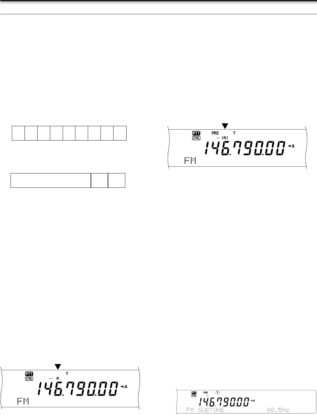
34
8 ENHANCED COMMUNICATIONS
AUTOMATIC REPEATER OFFSET
This function automatically selects an offset direction,
according to the frequency that you select on the
144 MHz band. The transceiver is programmed for
offset directions as shown below. To obtain an up-to-
date band plan for repeater offset direction, contact
your national Amateur Radio association.
Access Menu No. 43 and switch the function ON or
OFF. The default is ON.
K-type (U.S.A. and Canada versions)
This complies with the standard ARRL band plan.
All E-types (European versions)
Note:
◆
Automatic Repeater Offset does not function when Reverse is
ON. However, pressing [TF-SET] after Automatic Repeater
Offset has selected an offset (split) status, exchanges the receive
and transmit frequencies.
◆
If you change the offset direction by pressing
[0/ SHIFT/OFFSET] when Automatic Repeater Offset is ON, the
Shift direction on the above figure is applied when you change
the frequencies.
REVERSE FUNCTION
After programming an offset on the 29, 50, 144,
430/ 440 MHz, and 1.2 GHz (Optional) band, the
reverse function exchanges a separate receive and
transmit frequency. So, while using a repeater, you
can manually check the strength of a signal that you
receive directly from the other station. If the station’s
signal is strong, both stations should move to a
simplex frequency to free up the repeater.
Press [TF-SET] to switch the Reverse function ON
(or OFF) while the Shift function is active.
• “R” appears when the Reverse function is ON.
Note:
◆
If you press [TF-SET] and try to receive outside the available
receive frequency, the transceiver will not allow you to tune the
frequency. The Reverse function will not operate.
◆
Automatic Repeater Offset does not function while Reverse is
ON.
◆
You cannot switch Reverse ON or OFF while transmitting.
AUTOMATIC SIMPLEX CHECK (ASC)
ASC functions only when you have programmed an
offset on the 29, 50, 144, 430/ 440 MHz or 1.2 GHz
(Optional) band. While using a repeater, ASC
periodically monitors the strength of a signal that you
receive directly from the other station. If the station’s
signal is strong enough to allow direct contact without
a repeater, the ASC indicator on the display starts to
blink.
Press and hold [TF-SET] for approximately 1 second
to switch the function ON.
• The “[R]” indicator appears when the function is
ON.
• When direct contact is possible, the “[R]” indicator
blinks.
• To quit the function, press [TF-SET].
Note:
◆
Pressing Mic [PTT] causes the ASC indicator to stop blinking.
◆
ASC does not function if your transmit and receive frequencies
are the same (simplex operation).
◆
ASC does not function while scanning.
◆
Activating ASC while using Reverse switches Reverse OFF.
◆
If you recall a memory channel or the Call channel that has the
Reverse status ON, ASC is switched OFF.
◆
ASC causes received audio to be momentarily intermitted every
3 seconds.
TONE FREQ. ID SCAN
This function scans through all tone frequencies to
identify the incoming tone frequency on a received
signal. You can use this function to find which tone
frequency is required by your local repeater.
1Press [FUNC], [4/ TONE/SEL].
• The current tone frequency appears.
2Press [SCAN/ SG.SEL] to activate the Tone
Freq. ID.
• “T” blinks and every Tone frequency is
scanned. When the Tone frequency is
identified, the transceiver stops scanning and
the identified frequency is displayed.
• Press [SCAN/ SG.SEL] again to resume
scanning.
• Press [SCAN/ SG.SEL] to stop scanning while
the Tone frequency ID scan is active.
+−
−− +S
S
SS
144.0 145.5 146.4 147.0 147.6
145.1 146.0 146.6 147.4 148.0 MHz
S: Simplex
S
S
S: Simplex
–
144.0 146.0 MHz145.8145.6
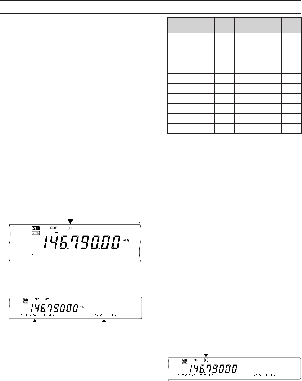
35
8 ENHANCED COMMUNICATIONS
FM CTCSS OPERATION
You may sometimes want to hear calls only from
specific persons. When using FM mode, the
Continuous Tone Coded Squelch System (CTCSS)
allows you to ignore (not hear) unwanted calls from
other persons who are using the same frequency. A
CTCSS tone is sub-audible and is selectable from
among the 38 standard tone frequencies. Select the
same CTCSS tone as the other stations in your
group. You will not hear calls from stations other than
those using the same CTCSS tone.
Note: CTCSS does not cause your conversation to be private. It
only relieves you from listening to unwanted conversations.
1Press [A/B] to select VFO A or VFO B.
•“tA” or “tB” appears to show which VFO is
selected.
2Select a band.
3Select an operating frequency.
4Press [FM/ AM/ NAR] to select FM mode.
• “FM” appears.
5Turn the SQL control to adjust the squelch.
6Press [6/ CTCSS/SEL] to switch the CTCSS
function ON (or OFF).
• “C T” appears when the function is ON.
7Press [FUNC], [6/ CTCSS/SEL].
• The current CTCSS frequency appears. The
default CTCSS frequency is 88.5 Hz.
8Turn the MULTI/ CH control to select the
appropriate CTCSS frequency.
• The selectable CTCSS frequencies are listed in
the following table.
9Press [FUNC], [6/ CTCSS/SEL] to complete the
setting.
.oN .qerF )zH( .oN .qerF )zH( .oN .qerF )zH( .oN .qerF )zH(
100.76114.79125.631138.291
209.17210.001223.141235.302
304.47315.301322.641337.012
400.77412.701424.151431.812
507.97519.011527.651537.522
605.28618.411622.261636.332
704.58718.811729.761738.142
805.88810.321828.371833.052
905.19913.721929.971
018.49028.131032.681
You will hear calls only when the selected tone is
received. To answer the call, press [SEND] or press
and hold Mic [PTT], then speak into the microphone.
Skip steps 7 and 8 if you have already programmed
the appropriate CTCSS frequency.
Note:
◆
When using split-frequency operation, select FM mode on both
VFOs to use CTCSS.
◆
Use Nos. 01 to 38 shown in the table above when selecting
CTCSS frequencies via Wireless Remote Control {page 82}.
◆
You can select a CTCSS frequency independent of a tone
frequency.
◆
You cannot use the CTCSS function with the Tone or DCS
functions.
CTCSS FREQ. ID SCAN
This function scans through all CTCSS frequencies to
identify the incoming CTCSS frequency on a received
signal. You may find this useful when you cannot
recall the CTCSS frequency that the other persons in
your group are using.
1Press [FUNC], [6/ CTCSS/SEL].
• The current CTCSS frequency appears.
2Press [SCAN/ SG.SEL] to activate the CTCSS
Freq. ID scan.
• “C T” blinks and every CTCSS tone frequency
is scanned. When the CTCSS frequency is
identified, the transceiver stops scanning and
the identified frequency is displayed.
• Press [SCAN/ SG.SEL] again to resume
scanning.
• Press [SCAN/ SG.SEL] to stop scanning while
the CTCSS tone frequency ID scan is active.
Note: Received signals are audible while scanning is in progress.
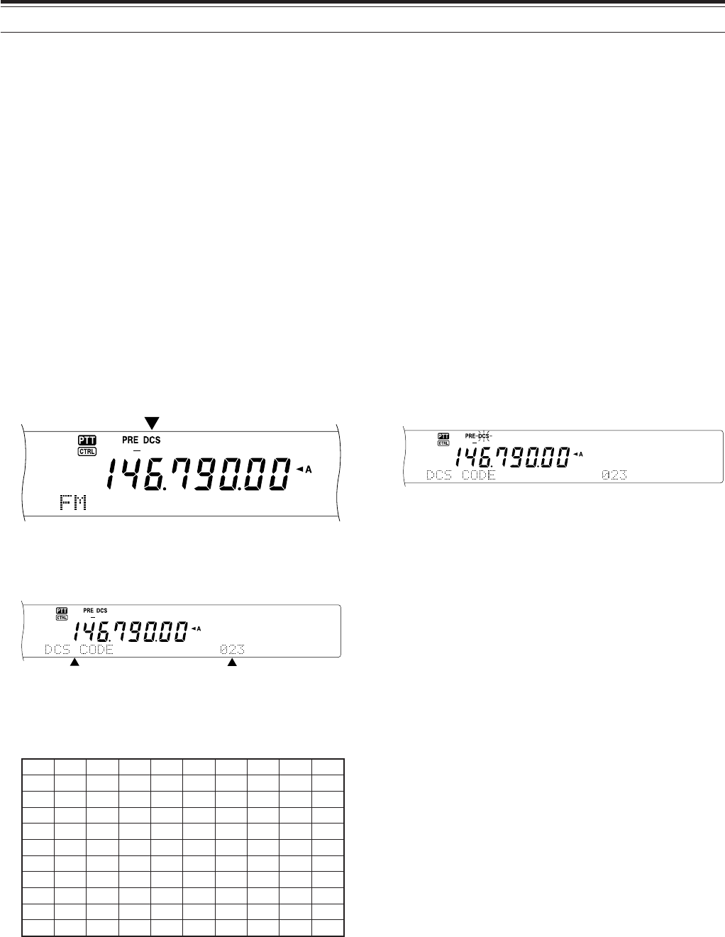
36
8 ENHANCED COMMUNICATIONS
FM DCS OPERATION
Digital Code Squelch (DCS) is another FM application
which allows you to ignore (not hear) unwanted calls.
It functions the same way as CTCSS. The only
differences are the encode/ decode method and the
number of selectable codes. For DCS, you can select
from 104 different codes listed in the table below.
1Press [A/B] to select VFO A or VFO B.
•“tA” or “tB” appears to show which VFO is
selected.
2Select a band.
3Select an operating frequency.
4Press [FM/ AM/ NAR] to select FM mode.
• “FM” appears.
5Turn the SQL control to adjust the squelch.
6Press [•/ DCS/SEL] to switch the DCS function
ON (or OFF).
• “DCS” appears when the function is ON.
7Press [FUNC], [•/ DCS/SEL].
• The current DCS code appears. The default is
023.
8Turn the MULTI/ CH control to select the
appropriate DCS code.
• The available DCS codes are listed in the
following table.
320560231502552133314564216137
520170431212162233324664426237
620270341322362343134305726437
130370541522562643234605136347
230470251622662153544615236457
630411551342172653644325456
340511651442472463254625266
740611261542603563454235466
150221561642113173554645307
350521271152513114264565217
450131471252523214464606327
9Press [FUNC], [•/ DCS/SEL] again to complete
the setting.
You will hear calls only when the selected code is
received. To answer the call, press [SEND] or press
and hold Mic [PTT], then speak into the microphone.
Skip steps 7 to 9 if you have already programmed the
appropriate DCS code.
Note: You cannot use DCS with the Tone or CTCSS functions.
DCS CODE ID SCAN
This function scans through all DCS codes to identify
the incoming DCS code on a received signal. You
may find this useful when you cannot recall the DCS
code that the other persons in your group are using.
1Press [FUNC], [•/ DCS/SEL].
• The current DCS code appears.
2Press [SCAN/ SG.SEL] to activate the DCS Code
ID scan.
•“DCS” blinks and every DCS code is scanned.
When the DCS code is identified, the
transceiver stops scanning and the identified
DCS ID is displayed.
•Press [SCAN/ SG.SEL] to resume scanning.
•Press [SCAN/ SG.SEL] to stop scanning while
the DCS code ID scan is active.
Note: Received signals are audible while scanning is in progress.
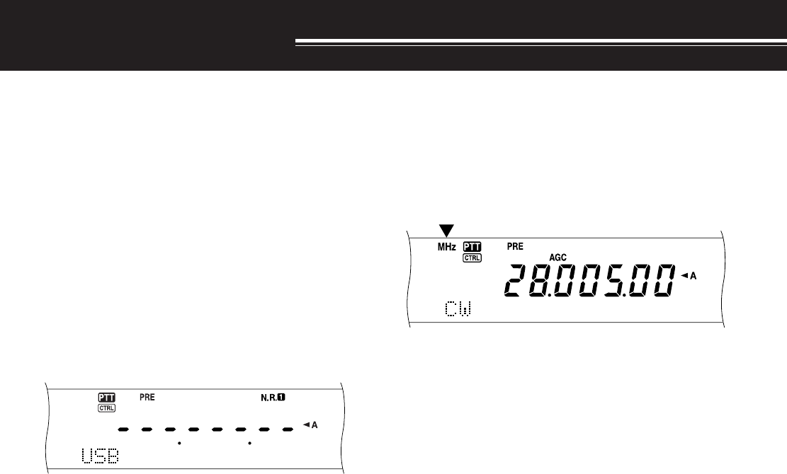
37
COMMUNICATING AIDS
RECEIVING
SELECTING YOUR FREQUENCY
In addition to turning the Tuning control or pressing
Mic [UP]/ [DWN], there are several other ways to
select your frequency. This section describes
additional methods of frequency selection that may
save you time and effort.
■Direct Frequency Entry
When the desired frequency is far removed from
the current frequency, directly entering a
frequency from the numeric keypad is usually the
fastest method.
1Press [ENT].
• “- - - . - - - . - - ” appears.
2Press the numeric keys ([0] to [9]) to enter
your desired frequency.
• Pressing [ENT] fills the remaining digits (the
digits you did not enter) with 0 and
completes the entry.
• To select 1.85 MHz for example, press [0],
[0], [0], [1], [8], [5], then press [ENT] to
complete the input (7 key strokes).
• To shorten the key strokes, you can also
use [•] as MHz. Press [1], [•] (MHz), [8],
[5], then press [ENT] to complete the input
(5 key strokes).
• Pressing [CLR] cancels the entry and
restores the current VFO frequency.
Note:
◆
You can enter the frequency in the range of 30.00 kHz to
1299.99999 MHz. Refer to the specifications for the
available frequency range.
◆
Attempting to enter a frequency that is outside the
selectable frequency range causes an alarm to sound.
The entered frequency is rejected.
◆
When the entered frequency does not meet the current
VFO frequency step size requirement, the nearest
available frequency is automatically selected (sub-
receiver). The nearest available frequency is
automatically selected after the entered frequency is
changed (main transceiver).
◆
When the 10 Hz digit (last displayed digit) is entered, the
digit 0 is automatically entered for the 1 Hz digit, and
frequency entry is completed. The 1 Hz digit is not
displayed.
◆
When an entered frequency is accepted, RIT or XIT will be
switched OFF, but the RIT or XIT offset frequency is not
cleared.
◆
After recalling memory channels 290 to 299 that have
Start and End frequencies stored, the receive frequency
can be changed by using Direct Frequency Entry within
the programmed range.
■Using 1 MHz Steps
Pressing [+]/ [–] on the front panel changes
Amateur bands. You can also use the MULTI/ CH
control to change the operating frequency in steps
of 1 MHz.
1Press [1MHz/ SEL].
• “MHz” appears.
2Turn the MULTI/ CH control.
• Clockwise increases the frequency, counter-
clockwise decreases the frequency.
3Press [1MHz/ SEL] to exit the function.
• “MHz” disappears.
If you prefer to change the frequency in steps of
100 kHz or 500 kHz steps rather than 1 MHz, press
[FUNC], [1MHz/ SEL] then turn the MULTI/ CH
control to select 100 kHz or 500 kHz.
Note: Even if 100 kHz or 500 kHz is selected for the [1MHz/ SEL]
key, the MHz icon appears.
■Quick QSY
To move up or down the frequency quickly, use the
MULTI/ CH control. Turning this control changes
the operating frequency in steps of 5 kHz for SSB/
CW/ FSK and 10 kHz for FM/ AM (below 60 MHz).
• If you want to change the default frequency
step size, press [FUNC], [9/ FINE/STEP].
Select 5 kHz, 6.25 kHz, 10 kHz, 12.5 kHz,
15 kHz, 20 kHz, 25 kHz, 30 kHz, 50 kHz or
100 kHz for FM/ AM, and 1 kHz, 2.5 kHz,
5 kHz, or 10 kHz for the other modes. The
default step size is 5 kHz for SSB/ CW/ FSK/
AM and 10 kHz for FM (below 60 MHz).
• When changing the operating frequency by
using the MULTI/ CH control, frequencies are
rounded such that new frequencies are
multiples of the frequency step size. To cancel
this function, access Menu No. 04 and select
“OFF” (default is ON).
• Within the AM broadcast band, the step size
automatically defaults to the frequency step
value in Menu No. 05. This step size can be
switched between 9 kHz (all E-types: ON) and
5 kHz (K-type: OFF) via Menu No. 05.
Note: The programmed frequency step size for the MULTI/ CH
control is stored independently for the HF/ 50 MHz, 144 MHz,
430/ 440 MHz and 1.2 GHz bands (main transceiver). You can
also set a different frequency step size for SSB, CW, FSK, AM
and FM modes. The sub-receiver also stores the independent
frequency step size for 118 MHz (K-type only), 144 MHz,
300 MHz (K-type only), and 430/ 440 MHz bands. You can also
set a different frequency step size for FM and AM.
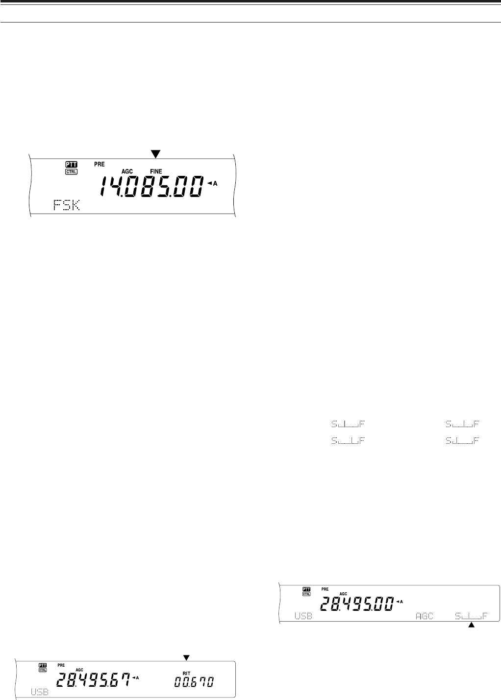
38
9 COMMUNICATING AIDS
■Fine Tuning
The default step value when turning the Tuning
control to change the frequency is 10 Hz for SSB,
CW, and FSK modes, and 100 Hz for FM and AM
modes. However, you can change the step size to
1 Hz for SSB, CW, and FSK modes, and 10 Hz for
FM and AM modes.
1Press [9/ FINE/STEP].
• “FINE” appears.
2Turn the Tuning control to select the exact
frequency.
3To quit the function, press [9/ FINE/STEP]
again.
• “FINE” disappears.
Note:
◆
Fine Tuning works only on the main transceiver.
◆
If Menu No. 03 is ON, you cannot perform fine tuning in FM
mode for all bands and AM mode for the 144 MHz/
430/ 440 MHz/ 1.2 GHz (TS-2000 optional) bands.
■Equalizing VFO Frequencies (A=B)
This function allows you to copy the frequency and
modulation mode of the active VFO to the inactive
VFO.
1Select the frequency and mode on VFO A or
VFO B.
2Press [A=B].
• The frequency and mode selected in step 1
are copied to the inactive VFO.
3Press [A/B] to confirm that the frequency was
copied.
RIT (RECEIVE INCREMENTAL TUNING)
RIT provides the ability to change your receive
frequency by ±20.00 kHz in steps of 10 Hz without
changing your transmit frequency. If the Fine Tuning
([9/ FINE/STEP]) function is ON, the step size
becomes 1 Hz. RIT works equally well with all
modulation modes and while using VFO or Memory
Recall mode.
1Press [RIT/ CW TUNE].
•“RIT” and the RIT offset appear.
2If required, press [CLEAR] to reset the RIT offset
to 0.
3Turn the RIT/ SUB control to change your receive
frequency.
4To turn off RIT, press [RIT/ CW TUNE].
• The receive frequency is returned to the
frequency that was selected prior to step 1.
Note:
◆
RIT works only on the main transceiver.
◆
When storing the frequency in a Memory channel with RIT
function ON, RIT offset frequency is added or subtracted to/ from
the VFO frequency. Then the calculated data is stored in the
Memory channel.
AGC (AUTOMATIC GAIN CONTROL)
When using a mode other than FM, AGC selects the
time constant for the automatic gain control circuit.
Selecting a slow time constant will cause the receiver
gain and S-meter readings to react slowly to large
input changes. A fast time constant causes the
receiver gain and the S-meter to react quickly to
changes in the input signal. A fast AGC setting is
particularly useful in the following situations:
• Tuning rapidly
• Receiving weak signals
• Receiving high-speed CW
Unlike other transceivers, the TS-2000’s digital AGC
circuit allows you to adjust the time constant from
slow to fast in 20 steps, where 1 is the slowest and
20 is the fastest. Furthermore, you can switch the
AGC OFF if you desire.
For your convenience, the following default AGC time
constant has already been programmed.
SSB: Level 7 CW: Level 12
FSK: Level 14 AM: Level 5
To change the default time constant:
1Press [8/ AGC/OFF].
• The AGC time constant scale appears on the
sub dot-matrix display.
2To select a slower time constant, turn the
MULTI/ CH control counterclockwise. The bar
indicator moves from F(ast) to S(low). To select
a faster time constant, turn the MULTI/ CH
control clockwise. The bar indicator moves from
S(low) to F(ast).
3If you want to turn the AGC OFF, press [FUNC],
[8/ AGC/OFF].
Note: You cannot adjust the AGC time constant on the sub-receiver.

39
9 COMMUNICATING AIDS
TRANSMITTING
VOX (VOICE-OPERATED TRANSMIT)
VOX eliminates the necessity of manually switching
to the transmit mode each time you want to transmit.
The transceiver automatically switches to transmit
mode when the VOX circuitry senses that you have
begun speaking into the microphone.
When using VOX, develop the habit of pausing
between thoughts to allow the transceiver to drop
back to receive mode briefly. You will then hear if
anybody wants to interrupt, plus you will have a short
period to gather your thoughts before speaking again.
Your listeners will appreciate your consideration as
well as respect your more articulate conversation.
VOX can be switched ON and OFF independently for
CW and the other modes, excluding FSK.
Press [VOX/ LEVEL] to toggle between VOX ON and
OFF.
• The VOX LED lights.
■Microphone Input Level
To enjoy the VOX function, take the time to
properly adjust the gain of the VOX circuit. This
level controls the capability of the VOX circuit to
detect the presence or absence of your voice. In
CW mode, this level cannot be adjusted.
1Select USB, LSB, FM, or AM mode.
2Press [VOX/ LEVEL] to switch the VOX
function ON.
• The VOX LED lights.
3Press [FUNC], [VOX/ LEVEL].
• The current VOX gain appears on the sub
dot-matrix display.
4While speaking into the microphone using your
normal tone of voice, adjust the setting (default
is 4) using the MULTI/ CH control until the
transceiver reliably switches to transmit mode
each time you speak.
• The selectable gain range is from 0 to 9.
• The setting should not allow background
noise to switch the transceiver to transmit
mode.
Note: The VOX gain level can be adjusted even if VOX is
switched OFF or while you are transmitting.
■Delay Time
If the transceiver returns to receive mode too
quickly after you stop speaking, your final word
may not be transmitted. To avoid this, select an
appropriate delay time that allows all of your
words to be transmitted without an overly long
delay after you stop speaking.
1Select USB, LSB, FM, or AM mode.
2Press [VOX/ LEVEL] to switch the VOX
function ON.
3Press [FUNC], [KEY/ DELAY].
• The current setting appears on the sub dot-
matrix display. The default is 50.
4While speaking into the microphone using your
normal tone of voice, adjust the MULTI/ CH
control such that the transceiver switches to
receive mode after you have stopped talking.
• The selectable range is from 5 to 100
(150 ms to 3000 ms) in steps of 5, or OFF.
5Press [FUNC], [KEY/ DELAY] to set the VOX
delay.
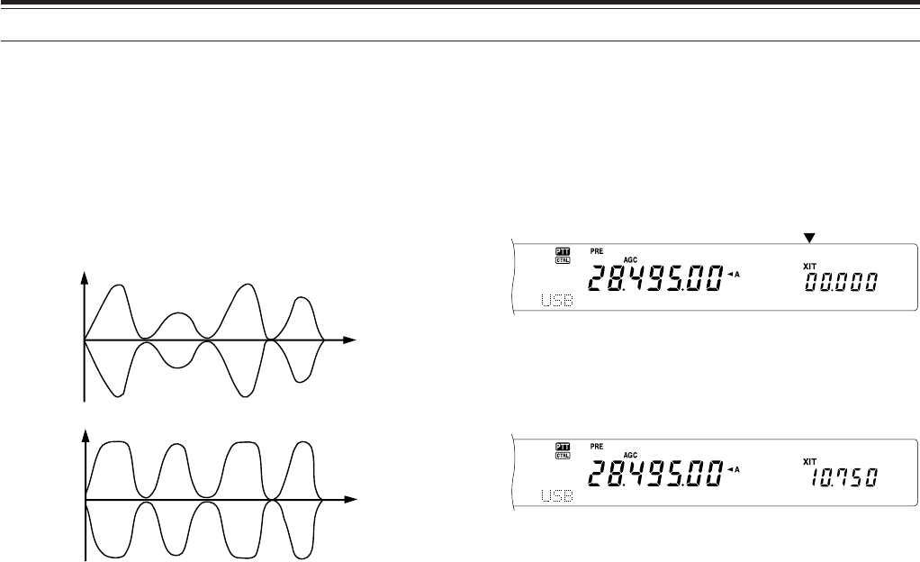
40
9 COMMUNICATING AIDS
SPEECH PROCESSOR
The Speech Processor levels out large fluctuations in
your voice while you speak. When using SSB, FM, or
AM mode, this leveling action effectively raises the
average transmit output power, resulting in a more
understandable signal. The amount of voice
compression is fully adjustable. You will notice that
using the Speech Processor makes it easier to be
heard by distant stations.
1Select USB, LSB, FM, or AM mode.
2Press [PROC/ LEVEL] to switch the Speech
Processor ON.
• The PROC LED lights.
3Press [FUNC], [PROC/ LEVEL] to enter the
Speech Processor input level adjustment mode.
4As you speak into the microphone, turn the
MULTI/ CH control so that the compression
meter indicates that the compression level is
around 10 dB while you speak.
• Using higher compression will not improve your
signal clarity or apparent signal strength.
Excessively compressed signals are more
difficult to understand due to distortion and are
less pleasant to hear than signals with less
compression.
5Press [FUNC], [PROC/ LEVEL] to exit the Speech
Processor input level adjustment.
6Press [MIC/ CAR] to enter the Speech processor
output level Adjustment.
• As you speak into the microphone, turn the
MULTI/ CH control so that the ALC meter
reflects according to your voice level but does
not exceed the ALC limit. Press [MIC/ CAR] to
exit when you finish the adjustment.
XIT (TRANSMIT INCREMENTAL TUNING)
Similar to RIT, XIT provides the ability to change your
transmit frequency by ±20.00 kHz in steps of 10 Hz
without changing your receive frequency. If the Fine
Tuning function is ON, the step size is 1 Hz.
1Press [XIT/ ALT].
• “XIT” and the XIT offset appear.
2If required, press [CLEAR] to reset the XIT offset
to 0.
3Turn the RIT/ SUB control to change your transmit
frequency.
4To turn XIT OFF, press [XIT/ ALT].
• The transmit frequency is returned to the
frequency that was selected prior to step 1.
Note:
◆
XIT works only on the main transceiver.
◆
The frequency shift set by the RIT/ SUB control is also used by
the RIT function. Therefore, changing or clearing the XIT offset
also affects the RIT offset.
◆
When the XIT frequency exceeds the limit of available
transmission frequency, the transceiver automatically stops
transmitting.
Transmit power
Transmit power
Time
Time
Speech
Processor
OFF
Speech
Processor
ON
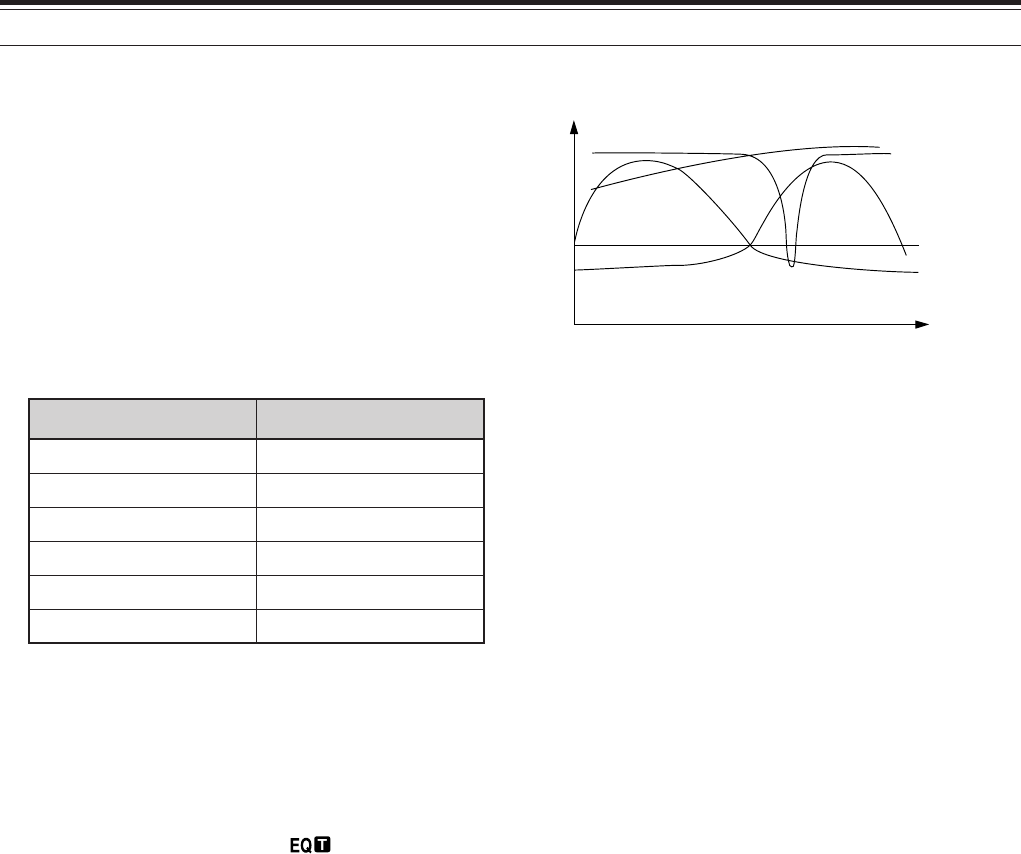
41
9 COMMUNICATING AIDS
CUSTOMIZING TRANSMIT SIGNAL
CHARACTERISTICS
The quality of your transmitted signal is important,
regardless of which on-air activity you pursue.
However, it is easy to be casual and overlook this fact
since you don’t listen to your own signal. The
following sub-sections provide information that will
help you tailor your transmitted signal.
■TX Filter Bandwidth (SSB/ AM)
Use Menu No. 22 to select one of the following
transmit bandwidths: 2.0 kHz, 2.2 kHz, 2.4 kHz
(default), 2.6 kHz, 2.8 kHz, or 3.0 kHz.
htdiwdnaB ycneuqerfdnabssaP
zHk0.2zH0052~005
zHk2.2zH0062~004
zHk4.2zH0072~003
zHk6.2zH0082~002
zHk8.2zH0092~001
1
zHk0.3zH0003~01
1
1If the Speech Processor is ON, the low-cut filter is set to 200 Hz
for 2.8 kHz and 3.0 kHz.
■TX Equalizer (SSB/ FM/ AM)
Use Menu No. 21 to change the transmit frequency
characteristics of your signal. You can select from
one of six different transmit profiles including the
default flat response. Selecting any of the following
items from the Menu causes “ ” to appear on
the display.
• Off (OFF):
The default frequency response for SSB, FM,
and AM.
• High boost (H BOOST):
Emphasizes higher audio frequencies; effective
for a bassy voice.
• Formant pass (F PASS):
Improves clarity by suppressing audio
frequencies outside the normal voice frequency
range.
• Bass boost (B BOOST):
Emphasizes lower audio frequencies; effective
for a voice with more high frequency
components.
• Conventional (CONVEN):
Emphasizes by 3 dB frequencies at 600 Hz
and higher.
• User (USER):
Reserved for the optional ARCP software. Off
is programmed at the factory as a default.
Frequency Response Curves
TRANSMIT INHIBIT
Transmit Inhibit prevents the transceiver from being
placed in transmit mode. No signal can be
transmitted when this function is ON even if the PTT
or [SEND] is pressed.
• TX Inhibit OFF: Transmission is allowed.
• TX Inhibit ON: Transmission is not allowed.
Switch the function ON or OFF via Menu No. 54. The
default is OFF.
CHANGING FREQUENCY WHILE TRANSMITTING
Moving your frequency while transmitting is usually
an unwise practice due to the risk of interfering with
other stations. However, if necessary, by using the
Tuning control you can change the operating
frequency while transmitting. You also can change
the XIT offset frequency while in transmit mode.
While transmitting, if you select a frequency outside
the transmit frequency range, the transceiver is
automatically forced to receive mode. If you selected
transmit mode by pressing [SEND], transmission will
not resume until you select a frequency inside the
transmit frequency range, at which time you must
press [SEND] again.
0.7 2.2
Amplitude
Audio
frequency
(kHz)
Bass boost
High boost
Off
Conventional
Formant pass
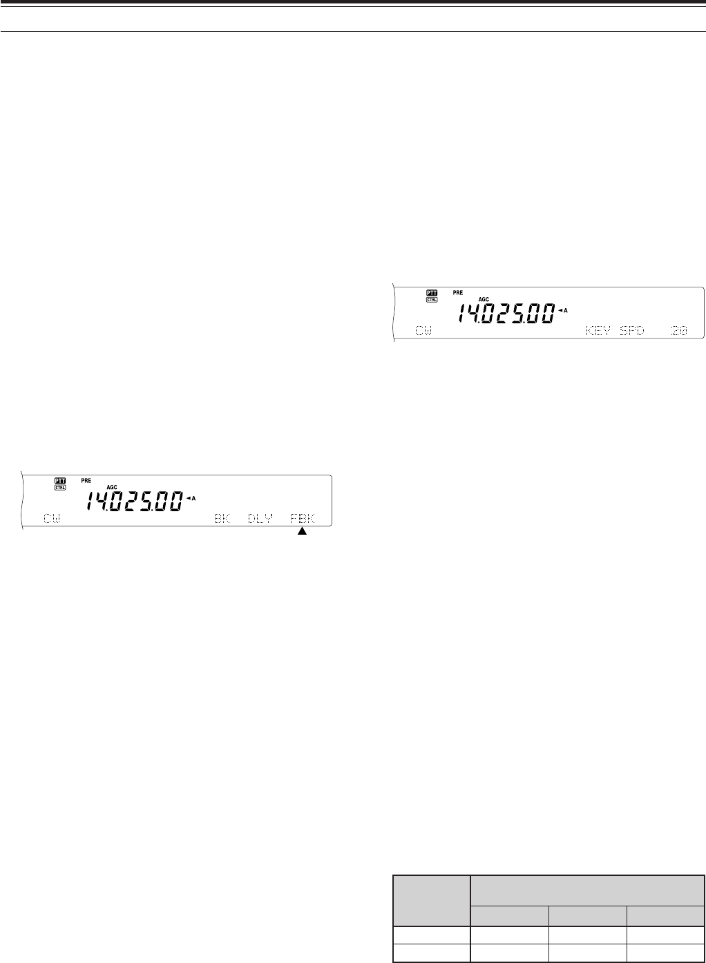
42
9 COMMUNICATING AIDS
CW BREAK-IN
Break-in allows you to transmit CW without manually
switching between transmit and receive modes. Two
types of Break-ins are available: Semi Break-in and
Full Break-in.
Semi Break-in:
When the key contacts open, the transceiver
automatically waits for the passage of the time period
that you have selected. The transceiver then returns
to receive mode.
Full Break-in:
As soon as the key contacts open, the transceiver
returns to receive mode.
USING SEMI BREAK-IN OR FULL BREAK-IN
1Press [CW/ FSK/ REV] to select CW mode.
• “CW” appears.
2Press [VOX/ LEVEL].
• The VOX LED lights.
3Press [FUNC], [KEY/ DELAY].
• The current setting (Full or delay time)
appears. The default is Full Break-in.
4Turn the MULTI/ CH control to select Full Break-in
or a delay time for Semi Break-in.
• Delay time ranges from 5 to 100 (50 ms to
1000 ms) in steps of 5.
5Begin sending.
• The transceiver automatically switches to
transmit mode.
•When FBK (Full Break-in) is selected:
The transceiver immediately switches to
receive mode when the key opens.
•When a delay time is selected:
The transceiver switches to receive mode after
the delay time that you have selected has
passed.
6Press [FUNC], [KEY/ DELAY] again.
Note: Full Break-in cannot be used with the TL-922/922A linear
amplifier.
ELECTRONIC KEYER
This transceiver has a built-in electronic keyer that
can be used by connecting a keyer paddle to the
transceiver’s rear panel. Refer to “Keys for CW
(PADDLE and KEY)” {page 3} for details regarding
this connection. The built-in keyer supports lambic
operation.
CHANGING KEYING SPEED
The keying speed of the electronic keyer is fully
adjustable. Selecting the appropriate speed is
important in order to send error-free CW that other
operators can copy solidly. Selecting a speed that is
beyond your keying ability will only result in mistakes.
You will obtain the best results by selecting a speed
that is close to the speed used by the other station.
1Press [CW/ FSK/ REV] to select CW mode.
• “CW” appears.
2Press [KEY/ DELAY].
• The current keying speed appears. The default
is 20 (WPM).
3While keying the paddle and listening to the
transmit sidetone, turn the MULTI/ CH control to
select the appropriate speed.
• The speeds range from 10 (WPM) to 60 (WPM),
in steps of 1. The larger the number, the faster
the speed.
4Press [KEY/ DELAY] again to complete the
setting.
Note: When using the semi-automatic “Bug” function, the selected
speed applies only to the rate that dots are sent.
AUTO WEIGHTING
The electronic keyer can automatically change the
dot/dash weighting. Weighting is the ratio of dash
length to dot length. The weighting changes with
your keying speed, thus making your keying easier
for other operators to copy.
Use Menu No. 33 to select AUTO, or 2.5 ~ 4.0 (in
steps of 0.1) fix weight ratio. The default is AUTO.
When the fix weight ratio is selected, the dot/dash
weight ratio is locked regardless of the keying speed.
■Reverse Keying Weight Ratio
Auto Weighting increases the weighting as you
increase your keying speed. However, the
electronic keyer also can decrease the weighting
as you increase your keying speed.
To switch this function ON, access Menu No. 34,
and select ON. The default is OFF.
esreveR gniyeK thgieW
)MPW(deepSgniyeK
52~01 54~62 06~64
FFO8.2:10.3:12.3:1
NO2.3:10.3:18.2:1
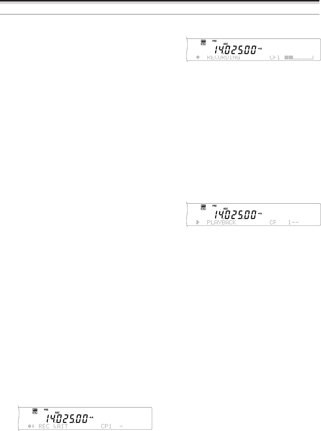
43
9 COMMUNICATING AIDS
BUG KEY FUNCTION
The built-in electronic keyer also can be used as a
semi-automatic key. Semi-automatic keys are also
known as “Bugs”. When this function is ON, dots are
generated in the normal manner by the electronic
keyer. Dashes, however, are manually generated by
the operator by holding the keyer paddle closed for
the appropriate length of time.
To switch this function ON, access Menu No. 35, and
select ON. The default is OFF.
Note: When the Bug Key function is ON, CW Message Memory
(see below) cannot be used.
CW MESSAGE MEMORY
This transceiver has three memory channels for
storing CW messages. Each memory channel can
store approximately 50 characters (equivalent of 250
dots). These memory channels are ideal for storing
contest exchanges that you want to send repeatedly.
Stored messages can be played back to check
message content or for transmitting.
The electronic keyer has a function that allows you
to interrupt playback and manually inject your own
keying. To switch this function ON, access Menu
No. 30, and select ON. The default is OFF.
The electronic keyer can also repeatedly play back
the message that you stored. To switch this function
ON, access Menu No. 29A and select ON. The
default is OFF.
For repetitive message playback, you can change
the interval between each series of messages.
Use Menu No. 29B, and select the time in the
range of 0 to 60 seconds.
Note:
◆
This function cannot be used when the Bug Key function is
ON.
◆
Operating the keyer paddle with Menu No. 30 OFF cancels
message playback. Even if message playback does not stop
because of your keying start timing, you can cancel playback
by pressing [CLR].
■Storing CW Messages
1Press [CW/ FSK/ REV] to select CW mode.
• “CW” appears.
2If VOX is ON, press [VOX/ LEVEL].
• The VOX LED turns off.
3Press [FUNC] and [1/ CH1/REC],
[2/ CH2/ REC], or [3/ CH3/REC] to select a
memory channel to be recorded.
4Begin sending using the keyer paddle.
• The message you send is stored in memory.
5To complete the message storage, press [CLR]
to stop.
• When the memory becomes full, recording
automatically stops.
Note: If you do not operate the keyer paddle after starting to
record a message, a pause is stored in the channel.
■Checking CW Messages without Transmitting
1Press [CW/ FSK/ REV] to select CW mode.
• “CW” appears.
2If VOX is ON, press [VOX/ LEVEL] to switch it
OFF.
3Press [1/ CH1/REC], [2/ CH2/REC], or
[3/ CH3/REC] to select the channel to be
played back.
• The message is played back.
• To play back the messages stored in the
other channels in sequence, press the
corresponding channel keys during
playback. Up to three channels can be
queued at the same time.
• While playing back the messages, you can
also adjust the keyer speed by pressing
[KEY/ DELAY] and turning the MULTI/ CH
control.
• To interrupt playback, press [CLR].
■Transmitting CW Messages
Messages can be transmitted using Semi Break-
in/ Full Break-in or manual TX/RX switching.
1Press [CW/ FSK/ REV] to select CW mode.
• “CW” appears.
2To use Semi Break-in/ Full Break-in, press
[VOX/ LEVEL]. The VOX LED lights.
Otherwise, press [SEND].
3Press [1/ CH1/REC], [2/ CH2/REC], or
[3/ CH3/REC] to select the channel to be
played back.
• The message is played back and
transmitted automatically.
• To transmit the messages stored in the
other channels in sequence, press the
corresponding channel keys during
playback. Up to three channels can be
queued at the same time.

44
9 COMMUNICATING AIDS
• While playing back the messages, you can
also adjust the keyer speed by pressing
[KEY/ DELAY] and turning the MULTI/ CH
control.
• To interrupt transmission, press [CLR].
4If you pressed [SEND] in step 2, press [SEND]
again to return to receive mode.
■Changing the Inter-message Interval Time
For the message playback repeat, select Menu
No. 29A and set it ON. You can also change the
interval playback time of the message. Use
Menu No. 29B, and select the time in the range
of 0 to 60 seconds, in steps of 1 second.
Note: Menu Nos. 29A and 29B settings are shared with the
voice communication modes when the optional DRU-3A is
installed.
■Changing the Sidetone Volume
Turning the MAIN AF or SUB AF control does not
change the CW sidetone playback volume. To
change the CW sidetone volume, access Menu
No. 13 and select OFF, or 1 to 9.
■Insert Keying
If you operate a CW keyer manually while playing
back a recorded CW message, the transceiver
stops playing back the message. However, during
contests or regular QSOs, you may sometimes
want to insert a different number or message at a
certain point in the recorded message.
In this case, first record the CW message as usual
{page 43}, without the number or message you
want to insert. Then, access Menu No. 30 and
select ON.
Now if you operate a CW keyer while you play
back a recorded message, the transceiver pauses
the playback of the recorded message, instead of
stopping it. When you finish sending the number
or message with the keyer, the transceiver
resumes playback of the message.
FREQUENCY CORRECTION FOR CW
If you operate both SSB and CW modes, you would
sometimes use SSB mode (USB or LSB) just to
watch and listen CW signals. It is fine just to
monitor those CW signals but you have experienced
that changing the mode from SSB to CW results
losing the target CW signal. This is because the
frequency on the display always shows the true
carrier frequency for all modes. If you want the
transceiver to shift the receiving frequency to trace
the receiving CW signal when changing the mode
from SSB (USB or LSB) to CW, switch this function
ON. The transceiver shifts the receiving frequency
when changing the mode from SSB to CW. So, you
can still hear the target signal and instantly transmit
the signal in CW, without adjusting the frequency.
1Press [MENU], then turn the MULTI/ CH control to
access Menu No. 37.
2Press [+] to select ON.
3Press [MENU] to store the settings and exit the
Menu mode.
CW REVERSE (RECEIVE)
This function pivots the BFO from the default position
(USB) to another position (LSB) in CW mode. It is
sometimes effective to remove the interfering signals
from the IF passband by pivoting the BFO.
1Press [FUNC], [CW/ FSK/ REV].
• “CWR” appears.
3To return to normal operation, press [FUNC],
[CW/ FSK/ REV] again.
AUTO CW TX IN SSB MODE
If you operate both SSB and CW modes, you can
configure the transceiver to change the operating
mode from SSB (USB or LSB) to CW and then
transmit in CW mode when you operate the CW
keyers.
1Press [MENU], then turn the MULTI/ CH control to
access Menu No. 36.
2Press [+] to select ON.
3Press [MENU] to store the settings and exit the
Menu mode.
Note: You must switch the CW break-in function ON to change the
mode and transmit in CW mode {page 42}.
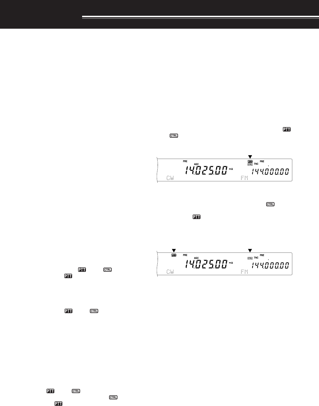
45
SUB-RECEIVER
SUB-RECEIVER
The TS-2000(X) transceiver is equipped with
2 independent receivers. The main transceiver can
receive from 30 kHz to the UHF band (or 1.2 GHz
band if the optional UT-20 is installed) while the sub-
receiver can receive signals in FM or AM mode on
the VHF (144 MHz) or UHF (430/ 440MHz) band.
You can assign the sub receiver to monitor the local
repeater activities or your club channel while you are
operating on the HF/ 50MHz or VHF/ UHF/ (Optional
1.2 GHz) bands with the main transceiver.
Since the TS-2000 also has a built-in TNC, you can
assign the sub-receiver to monitor the local DX
Packet Cluster channel activities without using an
external TNC. If a new DX station is reported to the
DX Packet Cluster, the transceiver automatically
displays the DX station data. If desired, you can
further transfer the DX frequency information to the
main tranceiver to watch and instantly make contact
with the DX station {page 53}.
TX BAND AND CONTROL BAND
In this manual, the frequency on the left of the display
is referred to as the MAIN band and the frequency on
the right is called the SUB band.
To understand how to control the MAIN band and
SUB band frequencies and functions, please note the
differences between the TX band and the Control
band, below.
TX BAND
Press [MAIN] to display the “ ” and “ ” icons on
the MAIN band. When “ ” is on the MAIN band
display, the MAIN band is currently selected as the
transmission band. You can use the MAIN band
frequency to transmit signals or to control the main
transceiver functions.
If you press [SUB], the “ ” and “ ” icons move to
the SUB band display. This means that the SUB
band is now selected as the transmission band and
controls the functions. You can use the SUB band
frequency to transmit signals or control the sub
receiver functions.
CONTROL BAND
On some occasions, you may need to adjust the
frequency and/ or functions for the band you are not
transmitting on. To do this, press [CTRL]. For
example, if both “ ” and “ ” are on the MAIN
band display, pressing [CTRL] will move “ ” to the
SUB band display. “ ” remains on the MAIN band
display. This allows you to continue transmitting on
the MAIN band while you adjust the functions of the
sub-receiver.
RECEIVING
ACTIVATING THE SUB-RECEIVER
Press the SUB AF control to switch the sub-receiver
ON or OFF. The orange LED above the SUB AF/ SQL
control lights when the sub-receiver is switched ON.
Note: When switching the sub-receiver ON or OFF, you may hear a
popping sound from the speaker. This is not a malfunction.
CONTROLLING THE SUB-RECEIVER
To control all the available functions of the sub-
receiver, press [SUB] to transfer the controls and
transmission capability to the sub-receiver. The “ ”
and “ ” icons move from the main transceiver to the
sub-receiver. When you press [SEND] or Mic [PTT],
the transceiver transmits on the SUB band frequency.
Or, if you would like to transmit and receive on the
MAIN band while adjusting the sub-receiver
functions, simply press [CTRL]. Only the “ ” icon
moves from the main transceiver display to the sub
display. The “ ” icon remains on the main
transceiver display. With this setup, you can continue
receiving and transmitting on the main transceiver
VFO frequencies while you are making adjustments
to the sub-receiver functions.
If you need to adjust only the frequency of the sub-
receiver, you can simply turn the RIT/ SUB control.
However, this works only when you are operating the
main transceiver without the RIT/ XIT functions.
When operating the main transceiver with the RIT/
XIT function, first switch OFF the RIT/ XIT function by
pressing [RIT/ CW TUNE] and/or [XIT/ ALT], or press
[CTRL] to move the controls to the SUB band. Then
turn the Tuning control, the MULTI/ CH control or the
RIT/ SUB control to adjust the SUB band frequency.
SELECTING A BAND
Press [SUB] or [CTRL] to assign the function
controls to the sub-receiver.
Press [+]/ [–] to select the 144 MHz or the
430/ 440 MHz band.
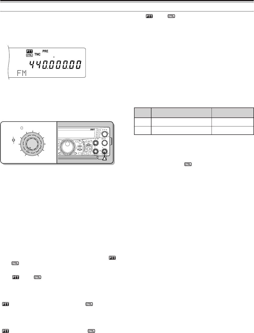
46
10 SUB-RECEIVER
The “ ” and “ ” icons are both on the sub-
receiver display:
• You can do all the above, plus transmit on the
SUB band frequency.
This transceiver provides many other methods for
selecting a frequency quickly. For further details, refer
to “SELECTING YOUR FREQUENCY” {page 37}.
SUB-RECEIVER PANEL METER
The multifunction meter measures the parameters
described in the table below. The S-meter appears
when in receive mode and the PWR meter appears
when in transmit mode. Peak readings for the
S- meter and PWR functions are held momentarily.
elacS yalpsiD etatSnoitcnuF
ShtgnertslangisdevieceRevieceR
RWPrewoptuptuotimsnarTtimsnarT
Note: Peak Hold readings cannot be deactivated.
SELECTING A MODE FOR THE SUB-RECEIVER
First, confirm that the “ ” icon is on the SUB band
display. If it is not, press [SUB] or [CTRL] to assign
the function controls to the SUB band.
The SUB band can only be used to transmit in FM
mode and receive in FM or AM mode. Press
[FM/ AM/ NAR] to toggle the operating mode for the
sub- receiver. The narrow bandwidth operation for
AM is not available for the SUB band frequency.
Refer to “NARROW BANDWIDTH FOR FM”
{page 29} for FM operation.
FM CTCSS OPERATION
You can assign an independent CTCSS tone to the
sub-receiver. Refer to “FM CTCSS OPERATION”
{page 35} for function and control details.
FM DCS OPERATION
You can assign an independent DCS code to the sub-
receiver. Refer to “FM DCS OPERATION” {page 36}
for function and control details.
TONE FREQ. ID SCAN
This function scans through all the tone frequencies
in order to identify the incoming tone frequency on
the receiving signal of the sub-receiver. Refer to
“TONE FREQ. ID SCAN” {page 34} for function and
control details.
DCS CODE ID SCAN
This function scans through all the DCS codes in
order to identify the incoming DCS code on the
receiving signal of sub-receiver. Refer to “DCS
CODE ID SCAN” {page 36} for function and control
details.
• Holding down the key changes the bands
continuously.
• If “MHz” is visible on the display, first press
[1MHz/ SEL] to exit from the 1 MHz Step Up/
Down mode.
ADJUSTING THE AUDIO FREQUENCY (AF) GAIN
Turn the SUB AF control clockwise to increase the
audio level and counterclockwise to decrease the
level.
SUB
CALL
C.IN
U
TO
S
B
S
B
SUB
S
EL
1MHz CTRL
MR
M VFO
MG.SEL
M.IN
M.IN
QUICK MEMO
SATL
A/B
M/S REV
TRACE
MAIN
MANUAL
RF
AF
SQL
SUB
CH
MULTI
BCMAIN
GAIN
VFO/CH
VFO/M A=B
SPLIT
MENU TF-
SET
MAIN SUB
SG.SEL
SCAN
RIT
CW TUNE 9.6k STA
RIT/SUB
CON
XIT
ALT
SET
CLEAR
P.C . T
_+
HF/VHE/UHF ALL MODE MULTI BANDER TS-2000
AF
SQL
Note: The position of the SUB AF control does not affect the volume
of beeps caused by pressing buttons. The audio level for Packet
operation is also independent of the SUB AF control setting.
ADJUSTING THE SQUELCH
Turn the SUB SQL control clockwise when no signals
are present, to select the squelch level at which
background noise is just eliminated. The SUB band
LED turns off when the squelch is ON.
SELECTING A FREQUENCY
When you operate both the main transceiver and the
sub-receiver at the same time, you will be in one of
the following conditions. First, check where the “ ”
and “ ” icons are on the display, then follow the
instructions below.
The “ ” and “ ” icons are both on the MAIN band
display:
• Turn the RIT/ SUB control to adjust the sub-
receiver frequency.
“” is on the SUB band display and “ ” is on the
MAIN band display:
• Turn the RIT/ SUB control to adjust the sub-
receiver frequency.
“” is on the MAIN band display and “ ” is on the
SUB band display:
• Turn the RIT/ SUB control, the MULTI/ CH control,
or the Tuning control to adjust the frequency. Or,
directly enter the frequency using the numeric
keypad {page 37}. However, the input frequency
must be within the sub-receiver frequency range.
The frequency you selected may round up to the
nearest workable frequency step size {page 37}.
You cannot transmit on the sub-band frequency.
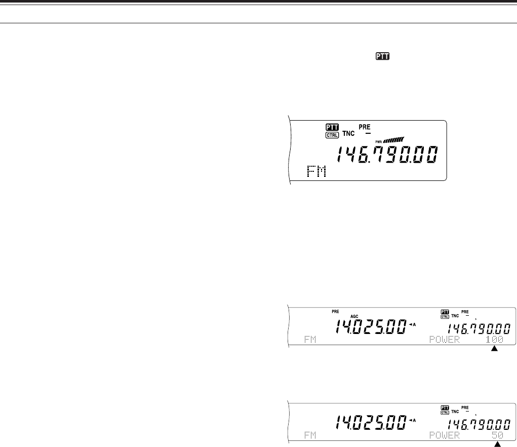
47
10 SUB-RECEIVER
ATTENUATOR
The attenuator reduces the level of received signals.
It is useful when there is strong interference from an
adjacent frequency. Since the main transceiver and
sub-receiver share the same antenna for the 144
MHz and 430/ 440 MHz bands, activating the
attenuator function for the sub-receiver also causes
the function to switch ON for the same band of the
main transceiver.
PRE-AMPLIFIER
The pre-amplifier amplifies the level of received
signals. It is useful when the receiving signal is weak.
If there is no strong interference from adjacent
frequencies, switch the pre-amplifier ON to raise the
receiving signal level. Since the main transceiver and
sub-receiver share the same antenna for the 144 MHz
and 430/ 440 MHz bands, activating the pre-amplifier
function for the sub-receiver also causes the function
to switch ON for the same band of the main
transceiver.
DUAL WATCH
If different frequency bands are set on the main
transceiver and sub-receiver, you can still monitor the
other band activities while transmitting on the TX
band. It is useful that you can still monitor the local
repeater frequency (VHF or UHF band) while you are
working on a DX station on the HF band of the main
transceiver.
If you have the same frequency band (VHF or UHF
band) for the main transceiver and sub-receiver, you
can monitor both frequencies independently at the
same time. However, both receivers will temporarily
mute when you transmit because the transceiver
shares the same 144 MHz and 430/ 440 MHz band
antenna between the main transceiver and sub-
receiver.
SCAN
All types of scanning are also available for the sub-
receiver. However, the operating frequency range is
limited to the sub-receiver’s frequency coverage.
Refer to “SCAN” {page 66} for details on how to
operate the scan function.
NOISE REDUCTION
Since the sub-receiver can receive only in FM or AM
mode, DSP noise reduction 1 (Line Enhanced) is
available to reduce the noise from the receiving
signals. Refer to “NOISE REDUCTION” {page 56} for
details on how to control and adjust the function.
TRANSMITTING
First, confirm that the “ ” icon is on the SUB band
display. Press [SEND] or press and hold Mic [PTT],
then speak into the microphone in your normal tone
of voice. When you finish speaking, press [SEND]
again or release Mic [PTT].
SELECTING A TRANSMIT POWER
You can also adjust the output power for FM mode on
the 144 MHz and 430/ 440 MHz bands when you are
operating the sub-receiver.
1Press [PWR].
• The current transmit power appears.
2Turn the MULTI/ CH control counterclockwise to
reduce the power or clockwise to increase the
power.
Note:
◆
The selectable range varies depending on the band and mode
{page 79}.
◆
Output power configuration is also reflected in the main
transceiver.
MICROPHONE GAIN
Access Menu No. 41 and select “LOW”, “MID”, or
“HIGH” for the microphone gain.
Note: When using the optional MC-90 microphone in FM mode,
select “HIGH” microphone gain. Microphone sensitivity is low in FM
mode; this may cause insufficient modulation. For other
microphones, select “MID” or “LOW”.
FM REPEATER OPERATION
You can also configure an independent repeater
offset frequency for the sub-receiver, if necessary.
Refer to “FM REPEATER OPERATION” {page 32} for
details.
REVERSE FUNCTION
Press [TF-SET] to switch the sub-receiver Reverse
function ON (or OFF). “R” appears while the Reverse
function is active on the sub-receiver. Refer to
“REVERSE FUNCTION” {page 34} for details.

48
10 SUB-RECEIVER
AUTOMATIC SIMPLEX CHECK (ASC)
You can also use ASC functions on the 144 MHz and
430/ 440 MHz bands of the sub-receiver. While using
a repeater, ASC periodically monitors the strength of
the uplink frequency to check the signals. Press and
hold [TF-SET] until “[R]” appears on the SUB band
display. Refer to “AUTOMATIC SIMPLEX CHECK”
{page 34} for function and control details.
TRANSMITTING A TONE
You can assign another Tone to the sub-receiver.
Refer to “TRANSMITTING A TONE” {page 33} for
function and control details.
MEMORY
You can also utilize all the memory functions
{page 58}, including the Quick Memory function
{page 64}, while you are operating the sub-receiver.
However, the operating frequency range is limited to
the sub-receiver’s frequency coverage. You cannot
recall any memory channels that are outside the sub-
receiver’s frequency coverage. These channels are
automatically skipped when they are recalled on the
sub-receiver.
49
SPECIALIZED COMMUNICATIONS
PACKET RADIO
Packet is a unit of data transmitted as a whole from
one computer to another, on a network. Packets can
be transmitted on radio waves as well as on
communications lines. Besides a transceiver and a
computer, all you need is a terminal node controller
(TNC) or Multimode Communications Processor
(MCP). One of the tasks of TNCs and MCPs is to
convert data packets to audio tones, and vice versa.
This transceiver has a built-in TNC which allows you
to use basic (not full) packet applications.
A variety of packet applications developed by hams
include packet bulletin board systems (PBBSs).
PBBSs are created and maintained by volunteers
called System Operators (SysOp). You may access
one of your local PBBSs to send e-mail, download
files, or obtain various useful information. Thousands
of PBBSs, which have formed a worldwide network,
relay e-mail to their intended destinations around the
world.
When you access a local PBBS for the first time, you
often need to register as a new user. After you are
successfully registered, it will then be available as
your home PBBS. E-mail addressed to you will be
held under a directory, called a mailbox, on your
home PBBS.
To send e-mail, you must designate the address of a
recipient, using his or her call sign and the call sign of
his or her home PBBS; ex. KD6NUH@KJ6HC. In this
example, the e-mail is addressed to KD6NUH whose
home PBBS is KJ6HC. If your home PBBS cannot
find KJ6HC in its address file to forward your mail,
you must designate the address in more detail. You
may enter “KD6NUH@KJ6HC.#ABC.CA”, or
“KD6NUH@KJ6HC.#ABC.CA.USA”, or up to
“KD6NUH@KJ6HC.#ABC.CA.USA.NA”, as
necessary. The complete address of a recipient living
in the U.S.A., for example, should include an
appropriate region code (preceded by a #), state,
country, and continent abbreviations, as above.
For further information, consult reference books
which should be available at any store that handles
Amateur Radio equipment. Web pages relating to
Packet will also be helpful. On Internet search
engines, use “Packet Radio” as key words to find
those Web pages.
PBBS
Note:
◆
Unlike a TNC, a Multimode Communications Processor (MCP)
serves as a communications interface in several digital modes
such as Packet, RTTY, and AMTOR. You can cause it to switch
among the modes by sending a single command from your
computer.
◆
If there is an amateur radio club in your area, consider becoming
a member. You can often learn more in an hour from
experienced hobbyists, than in a month of independent research.
Ask on the local repeaters, or contact your national amateur radio
organization (the ARRL in the U.S.A.) for information on local
amateur radio clubs. You’ll be glad you did.
BUILT-IN TNC
This transceiver has a built-in TNC which conforms to
the AX.25 protocol. Since the built-in TNC has been
designed to work with the Packet Cluster Tune
{page 53} and Sky Commander II+ {page 83}
functions, some of the enhanced TNC commands
may not be available. For the commands supported
by the built-in TNC, consult “BUILT-IN TNC
COMMAND LIST” starting on page 110. The AX-25
protocol is used for communication between TNCs.
The TNC accepts data from your personal computer
and assembles it into packets. It then converts those
packets to audio tones which the transceiver can
transmit. The TNC also takes audio tones from the
transceiver, converts them to data for the computer,
and checks for errors in the data.
In order to activate the built-in TNC, access Menu
No. 55 and select ON. The default is OFF. “PKT”
will appear to show that the built-in TNC is ON.
The TNC mainly functions in Command or Converse
mode. First, you should learn the difference between
these two modes.
• Command mode
When you select Packet mode, the TNC enters
Command mode. A “cmd:” prompt appears on the
computer screen. You can type commands from
the computer keyboard to change the settings of
the TNC. When in Converse mode, press
[Ctrl]+[C] on the keyboard to return to Command
mode.
• Converse mode
The TNC enters this mode when a link with the
target station is established. On the computer
keyboard, type an appropriate command and a
message if necessary, then press [Enter] or
[Return]. What you type is converted into packets
and transmitted over the air. When in Command
mode, type CONVERSE, CONV, or K to enter
Converse mode.
Note: The built-in TNC automatically reinitiates when a malfunction
is detected; this does not designate that the transceiver is defective.

50
11 SPECIALIZED COMMUNICATIONS
PREPARATION
1Connect the transceiver to your personal
computer (via an external TNC or MCP if desired).
• See “COMPUTER” {page 93} and “MCP AND
TNC” {page 95}.
2Install an appropriate terminal program onto the
personal computer.
• A variety of freeware and shareware programs
can be obtained in various ways. Consult your
reference material or other “packeteers”.
3Initiate the terminal program and set the following
parameters on the personal computer:
• Transfer rate (TNC/MCP <–> Computer):
9600 bps (default setting)
• Data length: 8 bit
• Stop bit: 1 bit
• Parity: Non-parity
• Flow control: Hardware
4Press [A/B] to select VFO A or VFO B.
5Access Menu No. 46 and select the main band or
the sub-band (default) as the data band.
• “TNC” appears on the data band.
• If you are using an external TNC or MCP,
access Menu No. 50E to make this selection.
The default is main band.
6Access Menu No. 47 and select 1200 bps (default)
or 9600 bps as the transfer rate between TNCs.
• You must select the same transfer rate as the
target station.
• If you are using an external TNC or MCP,
access Menu No. 50F to make this selection.
The default is 1200 bps.
7Select an operating frequency.
8Press [LSB/ USB/ AUTO] or [FM/ AM/ NAR] to
select LSB, USB, or FM mode.
9Access Menu No. 50A and select ON to activate
the DSP packet filter for the main transceiver.
10 Turn the HI/ SHIFT control to select the center
frequency of the packet mode. You can further
select either “NAR” (narrow) or “WID” (wide) for
the receiver filter width by turning the LO/ WIDTH
control.
ycneuqerFretneC edoMgnitarepO
zH000113KSP
zH0071)spb0021KSFA(tekcaP
zH0122)spb003KSFA(tekcaP
KSPKSP
Note:
◆
The packet (9600 bps) operation is not affected by the DSP
packet filter settings.
◆
The DSP packet filter works only on the main transceiver.
If you are using an external TNC or MCP, proceed
with the subsequent steps.
11 Following the instructions provided with your TNC
or MCP, enter the calibration mode so that you
can generate a mark condition.
• The MAIN band LED changes from green (RX)
to red (TX).
12 Access Menu No. 50B to select the appropriate AF
input level.
• Select a proper input level, so that the ALC
meter reflects within the ALC zone.
13 Exit the calibration mode.
• The MAIN band LED changes from red (TX) to
green (RX).
14 Access Menu No. 50C to select the appropriate
AF output level.
• You cannot use the AF control to make this
adjustment.
• If you have selected sub-band in step 5,
access Menu No. 50D instead.
The frequencies (measured in kHz) commonly used
for Packet are listed below:
adanaC/.A.S.U )acirfA/eporuE(1noigeRURA
0381~0081—
5363~02630063~0953
0017~0807—
05101~04101—
5.99041~5904121141~10141,99041~98041
01181~50181—
00112~0901202112~00112
98182~0218200392~00292,05182~02182
08705~00605—
090541~019441—
570144~579044520134~050034
DCD SENSE
You can also select the method for inhibiting the built-
in TNC from transmitting. Access Menu No. 48 and
select one of the two methods. The default is “TNC
BAND”.
TNC BAND:
The TNC does not transmit when signals are present
on the TNC (data) band.
MAIN&SUB:
The TNC does not transmit when signals are present
on the main transceiver or sub-receiver.
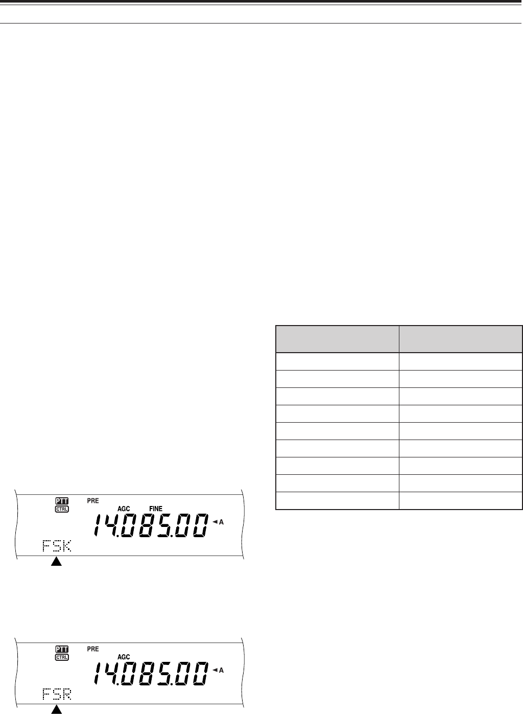
51
11 SPECIALIZED COMMUNICATIONS
RADIO TELETYPEWRITING (RTTY)
RTTY is the data communications mode with the
longest history. It was originally designed for use with
mechanical teletypewriters which were often used
before personal computers became common. Now
you can easily start operating RTTY with a personal
computer and MCP. Unlike Packet, each time you
type a letter, it is transmitted over the air. What you
typed is transmitted and displayed on the computer
screen of the recipient.
RTTY operation uses frequency shift keying (FSK)
and the 5-bit Baudot code or the 7-bit ASCII code to
transmit information.
For the cable connections, see “RTTY” {page 95}.
For further information, consult reference books
about Amateur Radio.
1Access Menu No. 38 and select an FSK shift.
• FSK shift is the difference in frequencies
between a mark and a space.
• The 170 Hz default is used on the Amateur
bands.
2Access Menu No. 39 and select a key-down
polarity.
• Select “NORMAL” to transmit a mark when
keying down or “INVERS” to transmit a space.
The default is “NORMAL”.
3Access Menu No. 40 and select high tone
(2125 Hz) or low tone (1275 Hz) for mark.
• High tone (default) is commonly used
nowadays.
4Select an operating frequency.
5Press [CW/ FSK/ REV] to select FSK.
• “FSK” appears.
6If necessary to be compatible with the other
station, press [FUNC], [CW/ FSK/ REV] to reverse
the transceiver to the upper sideband.
• “FSR” appears.
• Traditionally, the lower sideband is used for
FSK operation.
• Press [FUNC], [CW/ FSK/ REV] to return to
the lower sideband.
7Following the instructions provided with your MCP,
enter a command from your computer to select
transmit mode.
• The MAIN band LED changes from green (RX)
to red (TX).
• You may instead press [SEND] to manually
select the transmit mode.
8Begin sending data from your computer.
• Use Menu No. 50C to select the appropriate AF
output level. The AF control cannot be used
for this adjustment.
• Press [FUNC], [PWR/ TX MONI] to monitor
your signals. Press [FUNC], [PWR/ TX MONI]
again to quit this function.
9When finished transmitting, enter a command from
your computer to return to receive mode.
• The MAIN band LED changes from red (TX) to
green (RX).
• If you pressed [SEND] in step 7, press [SEND]
again.
The frequencies (measured in kHz) commonly used
for RTTY operation are listed below:
adanaC/.A.S.U 1noigeRURA )acirfA/eporuE(
0481~00812481~8381
)0953:XD(5463~50630263~0853
)0407:XD(0017~08075407~5307
05101~0410105101~04101
5.99041~070415.99041~08041
01181~0018190181~10181
00112~0701202112~08012
03942~0294292942~02922
05182~0708205182~05082
Note: You may adjust the carrier level when necessary. Press
[FUNC], [MIC/ CAR] to enter the adjustment mode. With a key down
condition, turn the MULTI/ CH control so that the ALC meter reads in
the ALC zone but does not exceed the upper ALC zone limit.
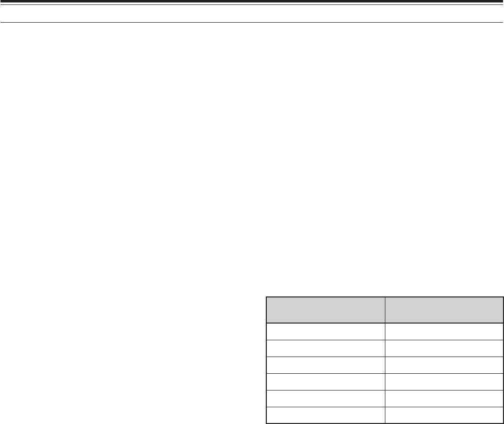
52
11 SPECIALIZED COMMUNICATIONS
AMTOR/ PacTOR/ CLOVER/ G-TOR/ PSK31
Besides Packet and RTTY, digital modes which have
been used among hams include AMTOR, PacTOR,
CLOVER, G-TOR, and PSK31. This manual does not
describe much about these modes. For details,
consult reference books about Amateur Radio.
AMTOR (AMateur Teleprinting Over Radio) has
brought amateur HF digital communication into the
computer age. It is the first error-free HF digital mode
by which data bursts (not steady stream of data) are
transmitted.
PacTOR (Packet Teleprinting On Radio) has
combined the best features of both AMTOR and
Packet to improve the efficiency of HF digital
communications. Like Packet and AMTOR, PacTOR
sends error-free data using a handshaking method.
Of all the Amateur Radio HF digital modes, CLOVER
offers the best overall performance using a
complicated modulation technique, automatic power
adjustment and other advanced features. It may
allow communications to be maintained under the
worst conditions.
G-TOR (Golay-coded Teleprinting Over Radio) is a
relatively new Amateur Radio digital mode currently in
use. G-TOR was developed specifically to handle the
adverse conditions of communicating, across the
solar system, with spacecraft during their missions.
PSK31 was developed by an RTTY enthusiast,
G3PLX, in the Great Britain. The operating technique
is very similar to the conventional Baudot-RTTY,
although more sensitive fine-tuning is required, as a
PSK31 signal requires a tuning accuracy of a few
Hertz. A special feature of PSK31 is that it allows the
entire ASCII character set, including the back space
character.
Your MCP should handle some or all of the above
modes. For available modes on your MCP, consult
the instruction manual for the MCP. For the cable
connections, see “MCP AND TNC” {page 95}.
On most HF bands, audio frequency shift keying
(AFSK) is used for the above modes. This method of
modulation uses audio tones therefore either LSB or
USB mode should be selected. Traditionally, LSB is
used, similar to RTTY, with the exception of AMTOR
which is normally operated in USB.
AMTOR activity can be found on or near 14075 and
3637.5 kHz. These are also good starting places
when searching for PacTOR, CLOVER, G-TOR, or
PSK31 stations.
Note: When using SSB mode for digital operation, use a fast AGC
setting and switch your Speech Processor OFF.
SLOW SCAN TV/ FACSIMILE
Slow-scan Television (SSTV) is a popular application
for transmitting still images over the air, from one
station to another. Instead of trying to describe your
station, simply showing it is much faster. Transmitting
images over the air requires a scan converter,
besides a transceiver. A scan converter transforms
images taken with a video camera into audio signals
that can be fed into your transceiver. The recipient’s
scan converter transforms audio signals back into
video images so that he or she can view them on a
TV set.
Nowadays instead of a scan converter, many hams
use a personal computer, a software application, and
an interface attached to the transceiver. This is much
cheaper, more flexible, and does not require a TV set.
In recent years, many low cost digital cameras have
become available. You can transfer images from
these cameras into your computer.
For further information, consult reference books about
Amateur Radio. The frequencies (measured in kHz)
commonly used for SSTV operation are listed below:
adanaC/.A.S.U 1noigeRURA )acirfA/eporuE(
7583,54830473~0373
17175407~5307
33241,0324153241~52241
0431254312~53312
0868258682~57682
005541—
Fax (facsimile) is one of the original image
transmission modes. Using this mode allows you to
exchange more detailed graphics than SSTV.
Amateur Radio fax functions much like old analog fax
systems. It scans paper and converts acquired
image data into a series of tones representing white
and black portions of the image. Because fax
requires longer transmission time, you should use it
only when band conditions are stable with strong
signals.
Popular fax frequencies include the following:
• 7245, 14245, 21345 (International Net), and
28945 kHz
Operating on SSTV or fax mainly involves learning
the functionality of your computer application or
accessory hardware that supports these modes.
Consult the instruction manual that comes with your
software or accessory equipment.
Note: When operating either SSTV or fax, use a fast AGC setting
and switch OFF your Speech Processor, for best results.
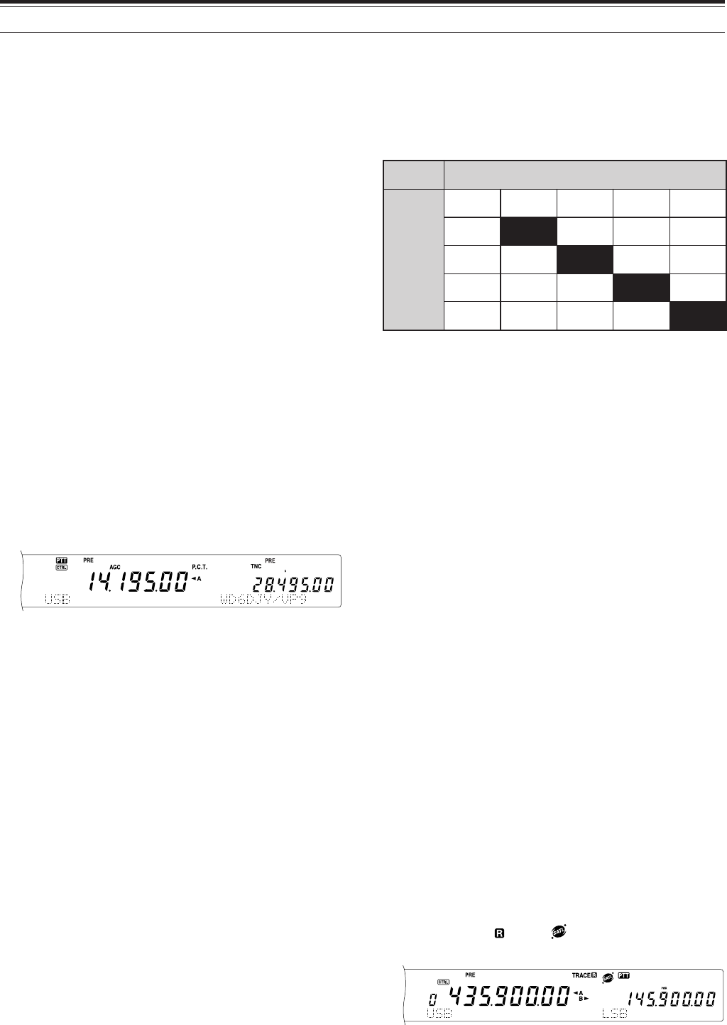
53
11 SPECIALIZED COMMUNICATIONS
DX PACKET CLUSTER TUNE
DX Packet Cluster is a packet network which consist
of nodes and stations who are interested in DXing
and contesting. If one station finds a DX station on
the air, he or she sends a notice to his or her node.
This node then passes the information to all its local
stations as well as another node. This transceiver
can display received DX information and hold the
latest information on up to 10 DX stations.
This transceiver is also capable of automatically
tuning in a reported DX station. In order to use the
Auto Tune function, access Menu No. 49A and select
“AUTO”; the default is “MANUAL”.
1Press [A/B] to select VFO A or VFO B.
2Press the SUB AF control to activate the sub-
receiver if it is switched OFF.
• The orange SUB LED lights {page 45}.
3Tune to the frequency of the target DX Packet
Cluster node on the sub-receiver.
4Access Menu No. 46 to confirm that “SUB” is
selected.
5Press [FUNC], [SET/ P.C.T.] to enter the Packet
Cluster Tune (P.C.T.) mode.
• Each time new DX Packet Cluster data is
received, the DX station’s callsign in Morse
code sounds and the information is displayed
on the sub-receiver as shown below:
6If you are not using the Auto Tune function, press
[SET/ P.C.T.].
• The main transceiver is tuned to the frequency
of the reported DX station, on the sub-receiver.
• Transmitting on the tuned frequency, the
transceiver exits the P.C.T. mode. Press
[FUNC], [SET/ P.C.T.] again to reactivate it if
necessary.
7Press [FUNC], [SET/ P.C.T.] to exit the P.C.T.
mode.
To access desired DX information in the P.C.T
memory, press QUICK MEMO [MR], then turn the
MULTI/ CH control. Press [SET/ P.C.T.] to tune the
main band to the selected station. Press QUICK
MEMO [MR] again to quit the DX information display.
The transceiver can be set to output a beep instead
of a Morse code when new DX Packet Cluster data is
received. Access Menu No. 49B and select “OFF”.
“VOICE” can also be set when you install the optional
VS-3 {page 91}.
Note:
◆
You cannot send DX information to a node using this function.
◆
The DX Packet Cluster data in memory is retained when the
transceiver is turned OFF. However, the sub-receiver’s
frequency display returns to the receiving frequency of the DX
Packet Cluster node.
SATELLITE OPERATION
Amateur satellites receive on one band and transmit
on another. Unlike in regular operation, Satellite
mode can handle uplink/ downlink frequency
combinations simultaneously in all operating modes
as shown below.
KNILPU
NWOD KNIL
dnaB ~FH zHM05 zHM441 /034 zHM044 zHG2.1
~FH zHM05 √√√
zHM441 √√√
/034 zHM044 √√ √
zHG2.1 √√√
Some satellites require a rotator that allows azimuth
and elevation control, plus a high-gain directional
antenna. The antenna must track the satellite which
travels from horizon to horizon. Even so, many hams
have been successfully using fixed omnidirectional
antennas. If you are using a directional antenna, it
would be wise to obtain a pass prediction program.
Doppler Shift is another aspect that you must take
into account when working the satellites. As a target
satellite travels away, frequencies on which you will
receive change. This transceiver has a function that
automatically keeps the sum or difference between
the two frequencies identical when you change the
receive frequency.
For further information, consult Internet Web pages
relating to Amateur satellites. On Internet search
engines, use “AMSAT” as key words to find those
Web pages. Or, you can directly go to the AMSAT
(the Radio Amateur Satellite Corporation) homepage
at http://www.amsat.org. From AMSAT Web pages,
you can download a variety of utilities, including pass
prediction programs, which will ease your satellite
operations.
BASIC OPERATION
When you enter the Satellite mode, you are always
controlling one of 10 Satellite Memory channels with
the adjustable frequency function. The Satellite
Memory channel number (0 ~ 9) appears on the main
transceiver’s display when you enter the mode.
1Press [SATL] to enter Satellite mode.
• The default downlink (435.9 MHz) and uplink
(145.9 MHz) frequencies appear.
• “TRACE”, “ ”, and “ ” appear to indicate the
current selections.
2On VFO A, tune to the downlink (RX) frequency of
the satellite.
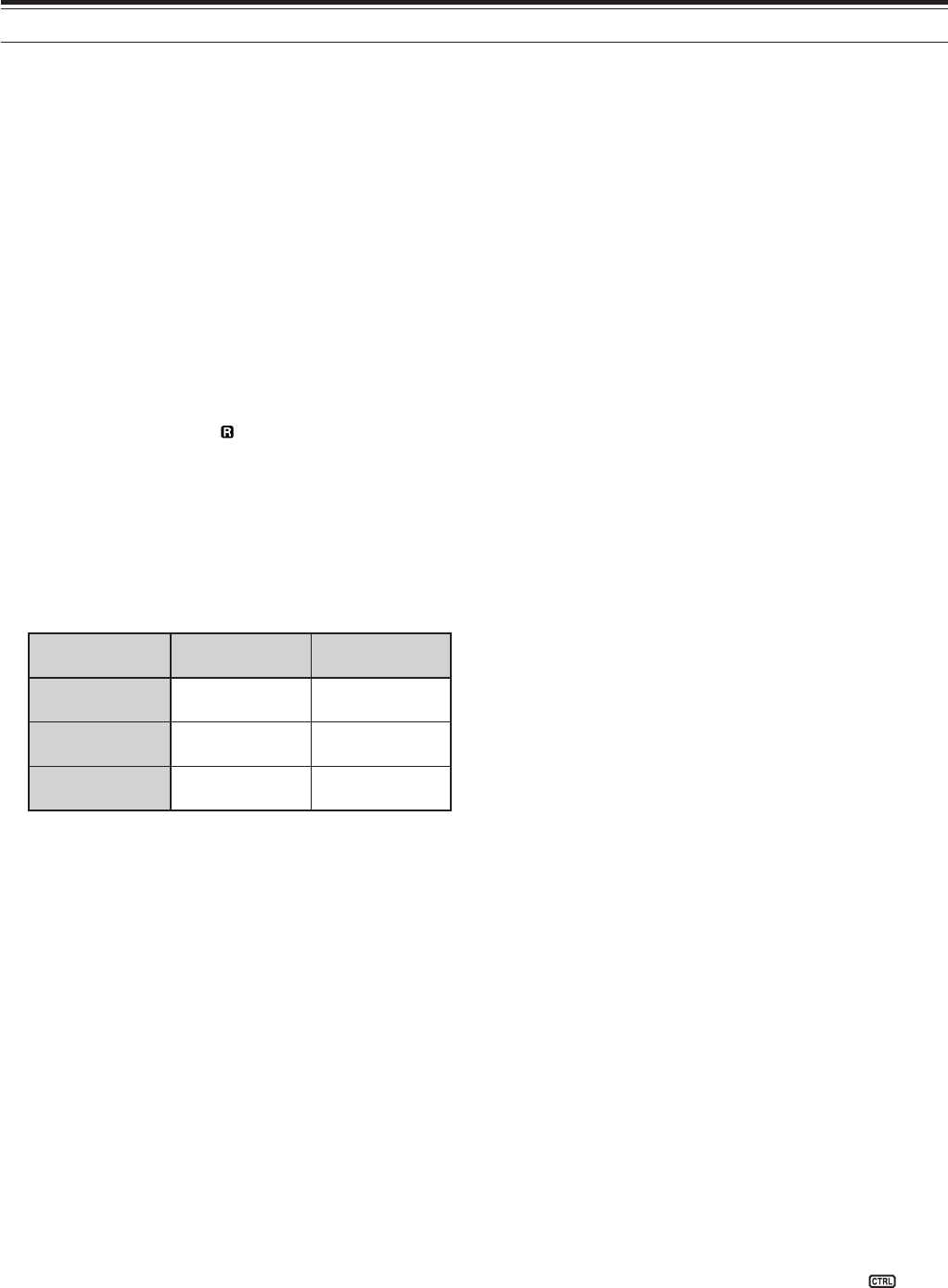
54
11 SPECIALIZED COMMUNICATIONS
3Press [LSB/ USB/ AUTO] or [CW/ FSK/ REV] to
select LSB, USB, or CW mode.
4As the Satellite moves, fine tune to the changing
downlink (RX) frequency of the satellite using the
Tuning control (adjusting the Doppler effect).
• As you adjust the downlink (RX) frequency, the
Trace function automatically changes the uplink
frequency so that the sum of the two
frequencies is kept the same (Reverse Trace).
• If necessary, press [A=B / TRACE] to quit the
Trace function. “TRACE” disappears.
• The trace function can also change the uplink
(TX) frequency so that the difference between
the two frequencies is kept the same (Normal
Trace).
5If you want to switch to the normal trace mode,
press [SPLIT / REV]. “ ” disappears.
6To adjust the frequency on the sub-band display
(normally the uplink frequency) without tracing,
turn the RIT/ SUB control. To adjust it using the
trace function, press [A/B / M/S] to swap the main
band frequency and sub-band frequency then turn
the Tuning control or MULTI/ CH control. The
following table shows which control to use when
adjusting frequencies with tracing ON and OFF.
ECART /
RECART NO ECART /
RECART FFO
gninuT lortnoc )lamroN( buSdnaniaMniaM
HC/ITLUM )esraoC(lortnoc buSdnaniaMniaM
BUS/TIR lortnoc buSbuS
STORING SATELLITE MEMORY CHANNELS
You can store all the above settings to one of 10
Satellite memory channels for the future operations.
1Press [M.IN], then turn the MULTI/ CH control to
select a channel from 0 to 9.
2Select your desired settings.
3Press [M.IN] again to store the selection to the
memory channel. To quit, press [CLR].
Note: The Satellite Memory channel does not hold the frequency
adjustment values when the channel is changed. So, when you
change the channel number or switch the transceiver OFF, the
adjustment frequency values are cleared if they are not stored by
pressing [M.IN].
RECALLING A SATELLITE MEMORY CHANNEL
1Press [VFO/M / VFO/CH].
• The MULTI/ CH LED lights.
2Turn the MULTI/ CH control to select the desired
Satellite Memory channel.
3Press [VFO/M / VFO/CH] to return to the
frequency adjustment mode.
SATELLITE CHANNEL NAME
You can name each Satellite Memory channel using a
maximum of 8 alpha-numeric characters. First, store
the settings to the Satellite Memory channel {above}.
To store the Satellite Channel name:
1Press [M.IN] then turn the MULTI/ CH control to
select the Satellite Memory channel.
2Press [DISP].
3An entry cursor appears. Select a character by
turning MULTI/ CH control, then move the cursor
using [SUB] or [MAIN]. You can also use the
other methods to enter the characters. Refer to
page 63 for details.
4Press [M.IN] to store the name to the Satellite
Memory channel. Press [CLR] to quit.
5The stored Satellite Memory name appears on the
main dot-matrix display.
QUICK MEMORY IN SATELLITE MODE
While in the Satellite mode, only 1 Quick Memory
channel is available. It uses Satellite Memory
channel 9 to store the settings. To store the settings
to the Quick Memory in Satellite mode, press
QUICK MEMO [M.IN]. The settings are stored to
Satellite Memory channel 9.
To recall the Quick Memory, press
QUICK MEMO [MR] or select Satellite Memory
channel 9, using the MULTI/ CH control. Satellite
Memory channel 9 is recalled.
CHECKING THE UPLINK FREQUENCY
When you need to monitor the uplink (TX) frequency,
press [TF-SET]. Each time you press [TF-SET], the
uplink (TX) frequency and the downlink (RX)
frequency are swapped.
USING XIT/ RIT IN SATELLITE MODE
You can also use the RIT or XIT function while in the
Satellite mode. Press [RIT/ CW TUNE] or [XIT/ ALT]
to activate the function. When the RIT or XIT function
is ON, the sub-band frequency display shows the
current RIT or XIT offset frequency instead of the
operating frequency. To clear the RIT or XIT offset
frequency, press [CLEAR].
Note: You cannot activate both the RIT and XIT functions at the
same time in the Satellite mode.
CHANGING THE FREQUENCY BAND
If you need to change the uplink and/or downlink
frequency band, press [CTRL] to move the “ ” icon
to the frequency band that you want to change.
Then, press [+]/ [–] to select the band you want to
operate.
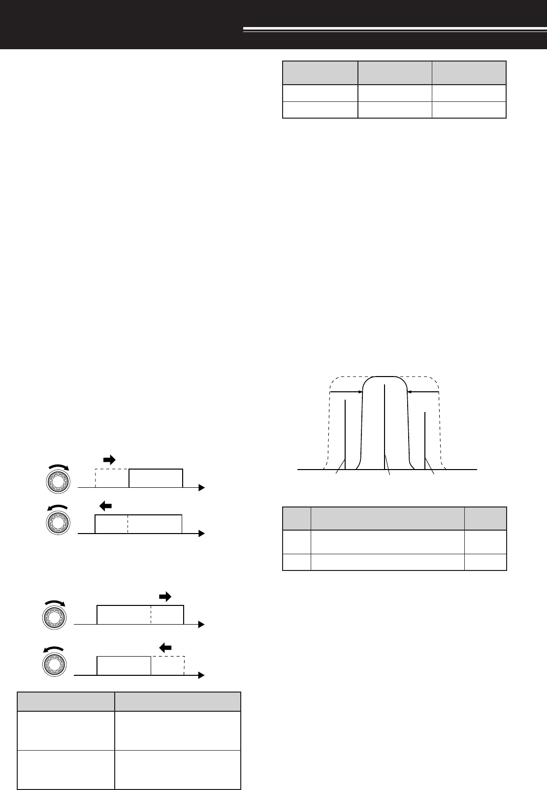
55
REJECTING INTERFERENCE
edoM tuc-woltluafeD )zH(yceuqerf tuc-hgihtluafeD )zH(ycneuqerf
MF/BSS0030062
MA0010005
4To return the display to the current operating
mode, press [DISP].
Note:
◆
The cut-off frequencies can be adjusted independently for
each operating mode. When you change the operating
mode, the previous setting is recalled for each operating
mode.
◆
When the Packet filter (Menu No. 50A) is ON, you cannot
change the DSP filter bandwidth. Switch the Packet filter
OFF to adjust the DSP filter bandwidth.
■CW/ FSK Modes
1Press [CW/ FSK/ REV] to select CW or FSK
mode.
2Press [DISP].
• The current filter selection appears.
3Turn the LO/ WIDTH control clockwise to
increase (wide) the bandwidth, or
counterclockwise to decrease (narrow) the
bandwidth.
edoM )zH(snoitceleShtdiwdnaB tluafeD )zH(
WC ,004,003,002,051,001,08,05 0002,0001,006,005 006
KSF0051,0001,005,0520051
4As for CW, you can further adjust the shift
frequency for passband. Turn the HI/ SHIFT
control to adjust the shift frequency from 400 to
1000 Hz in steps of 50 Hz. The default shift
frequency is 800 Hz.
5To return the display to the current operating
mode, press [DISP].
DSP FILTERS
KENWOOD digital signal processing (DSP)
technology is used for the functions described in this
section. Using DSP filtering, the TS-2000 frees you
from installing many analog filters for each operating
mode. Additionally, you can control the bandwidth,
cancel the multiple jamming beat, and reduce the
noise level using DSP filtering technology.
CHANGING THE RECEIVE FILTER BANDWIDTH
For improving interference reduction capability, this
transceiver also provides IF filters designed using
DSP technology. When in SSB, FM, or AM mode,
you can change the filter bandwidth by altering its low
and/or high cut-off frequency. For CW and FSK
modes, you can change the filter bandwidth by
directly specifying a bandwidth. Changing the filter
bandwidth does not affect the current receive
frequency.
Note:
◆
The receive filter bandwidth can be changed only on the main
transceiver.
◆
The IF DSP filter is not available in FM mode.
■SSB/ FM/ AM Modes
1Select SSB, FM, or AM mode.
2Press [DISP].
• The current filter selection appears.
3Turn the LO/ WIDTH control clockwise to raise
the low cut-off frequency, or counterclockwise
to lower the low cut-off frequency.
LO/ WIDTH
f
f
Turn the HI/ SHIFT control clockwise to raise
the high cut-off frequency, or counterclockwise
to lower the high cut-off frequency.
HI/ SHIFT
f
f
tsujdA )zH(snoitceleSycneuqerF
HTDIW/OL ,004,003,002,001,05,0 ,009,008,007,006,005 0001
TFIHS/IH ,0002,0081,0061,0041 ,0082,0062,0042,0022 0005,0004,0043,0003
Interfering
signal Desired
signal Interfering
signal
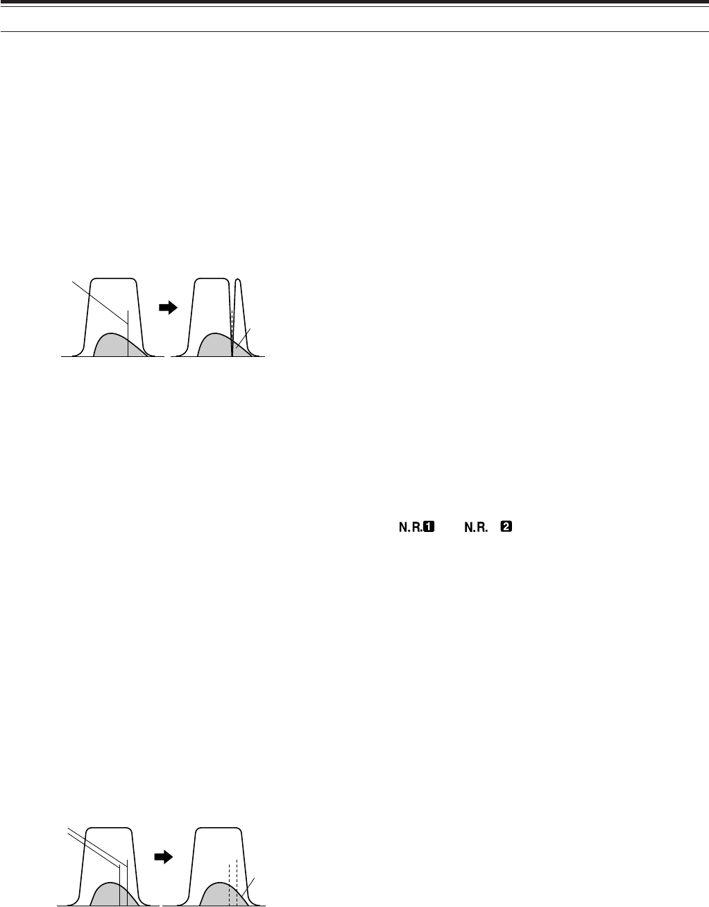
56
12 REJECTING INTERFERENCE
NOTCH FILTER (SSB)
Auto Notch filter automatically locates and attenuates
any single interfering tone within the receive pass
band. This function operates digitally at the IF filter
level, hence it can affect your S-meter reading and
may also affect (slightly attenuate) your desired
signal. However, controlling the AGC level by
notching out the strong interfering beat signals could
bring up the desired SSB signal that is covered by the
interfering beat signal. If the interfering tone is weak,
you may find that Beat Cancel eliminates them more
effectively.
Before
Interfering
tones
After
Receive pass band
Desired
signal
Press [A.N./ LEVEL] to toggle the Auto Notch Filter
ON and OFF.
•“A.N.” appears when the function is ON.
•The interfering beat signals are notched out.
If the interfering beat signals change the tone
frequency randomly, you can adjust the Auto Notch
level.
Press [FUNC], [A.N./ LEVEL] to access the Auto
Notch level adjustment, then turn the MULTI/ CH
control to select the level from FIX, and 1 to 4.
Level 1 is the slowest beat tone tracking speed and
Level 4 is the fastest. FIX terminates the beat tone
tracking. Adjust this pamameter manually to remove
the beat signal if necessary.
AUTO BEAT CANCEL (SSB/ AM)
Auto Beat Cancel uses an adaptive filter and
attenuates more than one cyclic interference within the
receive pass band. The adaptive filter changes its
characteristics according to the nature of the signal
being received at any given moment. You can use
automatic Beat Cancel when in SSB or AM mode.
Before
Interfering
tones
After
Receive pass band
Desired
signal
Press [B.C./ MANUAL] to toggle between the Auto
Beat Cancel ON and OFF.
•“B. C.” appears when the function is ON.
•If desired, you can manually control the beat
cancel frequency.
MANUAL BEAT CANCEL (ALL MODES)
Press [FUNC], [B.C./ MANUAL], then turn the
MANUAL BC control to select the single Beat Cancel
frequency manually. You can select the beat cancel
frequency from approx. 300Hz to 3000 Hz by turning
the control. Turn the control clockwise to select a
higher frequency and counterclockwise to select a
lower frequency.
Since the DSP Beat Cancel processes the incoming
signals at the AF stage, strong beat signals may
control the AGC, then weaken the target signal level.
In this case, use the Auto Notch Filter instead, to
remove the beat signal from the IF passband filter.
Note: While adjusting the MANUAL BC control, the transceiver
clicks. This is not a malfunction.
NOISE REDUCTION
(N.R. 1: ALL MODES, N.R. 2: SSB/ CW/ FSK/ AM)
This transceiver provides two types of Noise Reduction
functions (1 and 2) for reducing random noise which
interferes with the desired signal. Trying them both is
the easiest way to judge which function works more
effectively under the current conditions. Normally,
select Noise Reduction 1 (Line Enhanced) in SSB
mode and Noise Reduction 2 (SPAC) in CW mode.
Press [N.R./ LEVEL] to toggle between Noise
Reduction 1, Noise Reduction 2, and OFF.
•“ ” or “ ” appears, depending on which
function is selected.
■Setting the N.R. 1 Level Adjustment
The Noise Reduction 1 (Line Enhanced Method)
uses an adaptive filter to reduce the noise element
from the received signals. When the S/N ratio is
reasonably good in SSB, using N.R. 1 will improve
the S/N further.
While N.R. 1 is ON, you can further adjust the noise
reduction level by pressing [FUNC], [N.R./ LEVEL],
then turn the MULTI/ CH control to select the level
from 1 to 9 or AUTO. The default is AUTO.
■Setting the N.R. 2 Time Constant
You can change the correlation time for Noise
Reduction 2 (SPAC). When in SSB mode, select
the correlation time that allows you to hear signals
with more clarity. When receiving CW, it is best to
select the longest correlation time that allows
reliable reception. The longer the correlation time,
the better the S/N ratio.
When N.R. 2 is ON, press [FUNC],
[N.R./ LEVEL], then turn the MULTI/ CH control to
select the correlation time from 2 ms to 20 ms.
The default is 20 ms.
Note:
◆
Using Noise Reduction 2 in SSB mode may lower the clarity of
signals or induce pulse noise, depending on the conditions.
◆
Only Noise Reduction 1 is available for the sub-receiver.
However, the level cannot be adjusted.
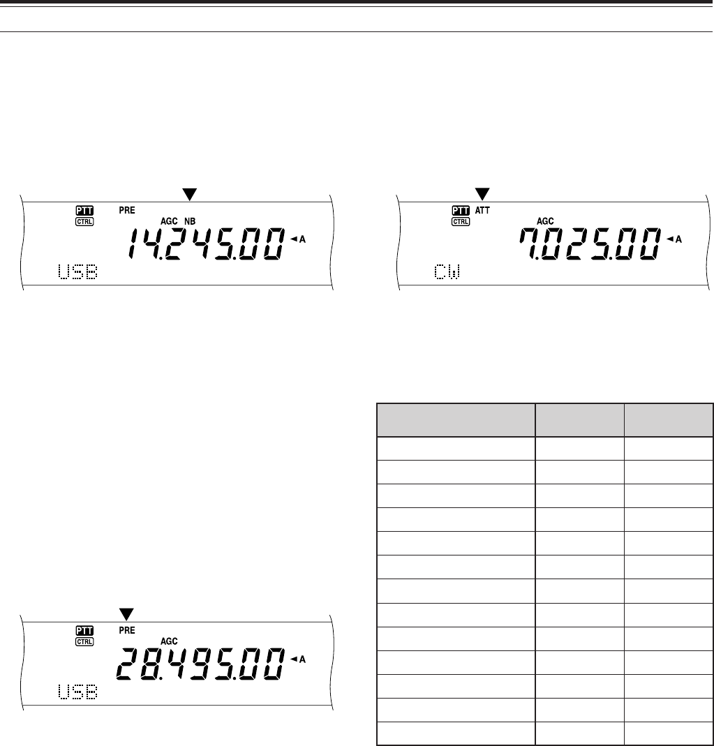
57
12 REJECTING INTERFERENCE
NOISE BLANKER
Noise Blanker was designed to reduce pulse noise
such as that generated by automobile ignitions.
Noise Blanker does not function in FM mode.
Press [7/ NB/ LEVEL] to toggle between the Noise
Blanker ON and OFF.
• “NB” appears when the function is ON.
You can further adjust the Noise blanker level from
1 to 10. The default level is 6.
Press [FUNC], [7/ NB/ LEVEL], then turn the
MULTI/ CH control to adjust the noise blanker level.
• “NB LEVEL” and the current level appear on the
sub dot-matrix display.
Note: Noise Blanker is available only for the main transceiver in
SSB, CW, FSK, and AM modes.
PRE-AMPLIFIER
Switching the Pre-amplifier OFF may help reduce
interference from adjacent frequencies.
Press [PRE/ LOCK A] to toggle between the
Pre-amplifier ON and OFF.
• “PRE” appears when the function is ON.
The ON/OFF setting will be automatically stored in
the current band. Each time you select the same
band, the same setting will be automatically selected.
The frequency range of each band is provided in the
following table (under “ATTENUATOR”).
Note: If the same frequency (144 MHz or 430 (440) MHz) band is
selected on both the main transceiver and the sub-receiver, the
pre-amplifier can be switched ON or OFF for both receivers. This
is because the main transceiver and sub-receiver share the same
antenna.
ATTENUATOR
The Attenuator reduces the level of received signals.
This function is useful when there is strong
interference from adjacent frequencies.
Press [ATT/ F LOCK] to toggle the Attenuator ON
and OFF.
• “ATT” appears when the function is ON.
The ON/OFF setting will be automatically stored in
the current band. Each time you select the same
frequency band, the attenuator setting will be
automatically recalled.
The frequency range of each band is shown below.
sdnaBycneuqerF )zHM( reifilpma-erP )tluafeD( rotaunettA )tluafeD(
5.2~30.0FFOFFO
1.4~5.2FFOFFO
5.7~1.4FFOFFO
5.01~5.7NOFFO
5.41~5.01NOFFO
5.81~5.41NOFFO
5.12~5.81NOFFO
5.52~5.12NOFFO
0.03~5.52NOFFO
0.06~0.03NOFFO
003~811NOFFO
215~003NOFFO
0031~0421NOsyawlAFFOsyawlA
Note:
◆
If the same frequency (144 MHz or 430/ 440 MHz) band is
selected on both the main transceiver and the sub-receiver, the
attenuator can be switched ON or OFF for both receivers. This is
because the main transceiver and sub-receiver share the same
antenna.
◆
Available receiving frequencies in the above frequency bands
vary, depending on the market code. Refer to the Specifications
{page 106} for details.
◆
If 118 ~ 135.995 MHz, 155 ~ 173.995 MHz or 220 ~ 229.995 MHz
is selected for the sub-receiver, the pre-amplifier cannot be turned
ON (K-type only).
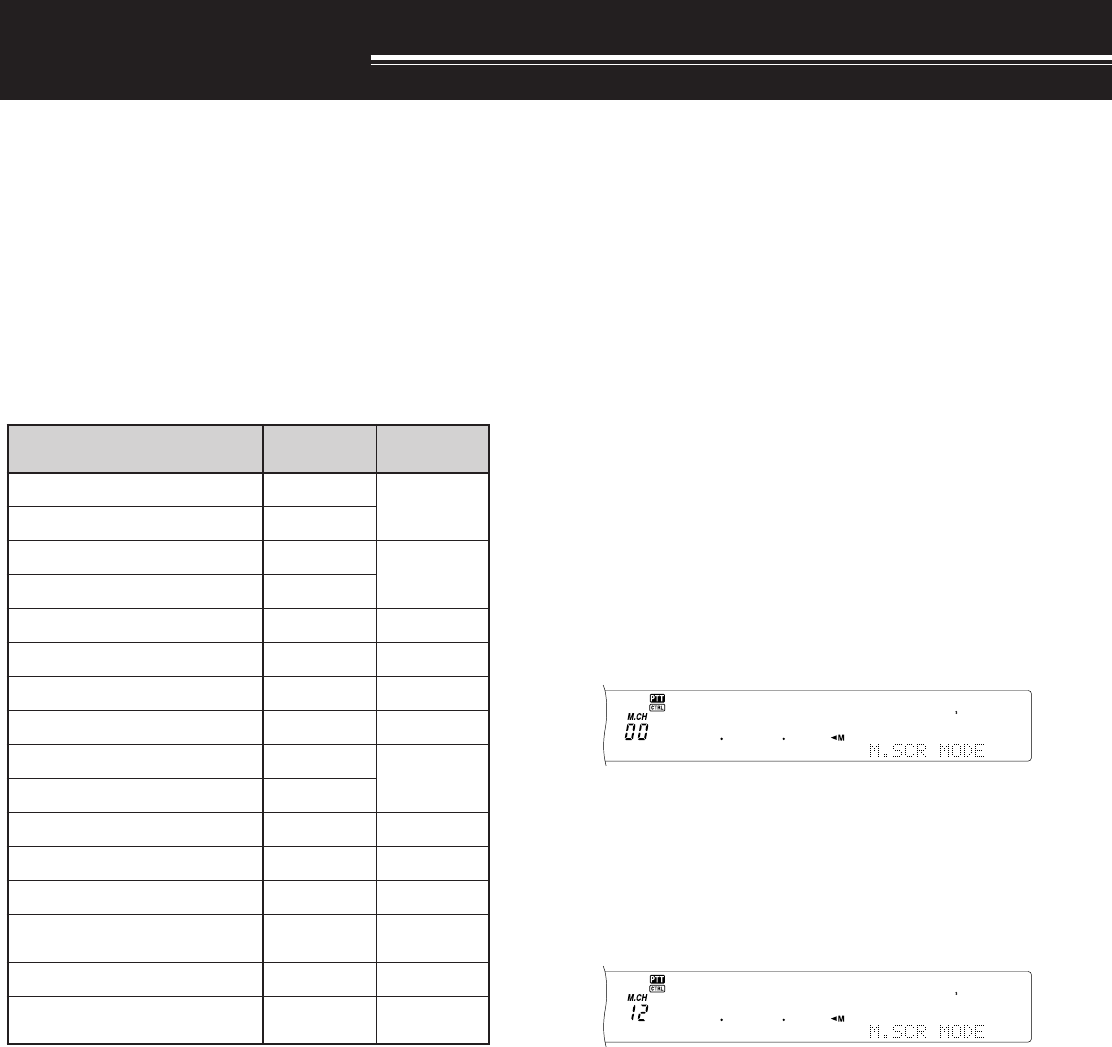
58
MEMORY FEATURES
MEMORY CHANNELS
The TS-2000(X) provides you with 300 memory
channels, numbered 00 to 299, for storing operating
frequency data, modes and other information.
Memory channels 00 to 289 are called Conventional
Memory Channels. Memory channels 290 to 299 are
designed for programming VFO tuning ranges and
scan ranges. The data you can store is listed below:
Conventional memory is used for storing data you
will often recall. For example, you may store the
frequency where you regularly meet your club
members.
retemaraP lennahC 982~00 lennahC 992~092
ycneuqerfXRseY seY
1
)xelpmis(
ycneuqerfXTseY
edomXRseY seY
1
)xelpmis(
edomXTseY
seicneuqerfdnE/tratSoNseY
ycneuqerftesffOseYseY
noitceridtfihSseYseY
edomesreveRseYseY
ezispetsycneuqerfXRseY seY )xelpmis(
ezispetsycneuqerfXTseY
ycneuqerfenoTseYseY
ycneuqerfSSCTCseYseY
edocSCDseYseY
edomSCD/SSCTC/enoT FFO/NO seYseY
emanyromeMseYseY
tuokcoLlennahCyromeM FFO/NO seY
1
seY
1
1Changing the data after recalling a memory channel overwrites the
contents of the channel.
STORING DATA IN MEMORY
There are 2 methods used for storing transmit/receive
frequencies and associated data in memory channels
00 to 289. Use either method, depending on the
relationship of the receive and transmit frequencies
you store:
• Simplex channels:
RX frequency = TX frequency
• Split-frequency channels:
RX frequency ≠ TX frequency
Memory channels 290 to 299 can also be used as
simplex channels.
Note: When RIT or XIT is ON, the frequency that includes the RIT or
XIT offset will be stored.
■Simplex Channels
1Press [A/B] to select VFO A or VFO B.
•“tA” or “tB” appears to show which VFO
is selected.
2Select the frequency, mode, etc. to be stored.
3Press [M.IN] to enter Memory Scroll mode.
• To exit Memory Scroll mode and abort the
storage process, press [CLR].
4Turn the MULTI/ CH control, or press Mic [UP]/
[DWN] to select a memory channel.
• You can also select a channel by entering a
3-digit number, such as 012, using the
numeric keys.
5Press [M.IN] again to store the data.
• The previous data stored in the channel is
overwritten.
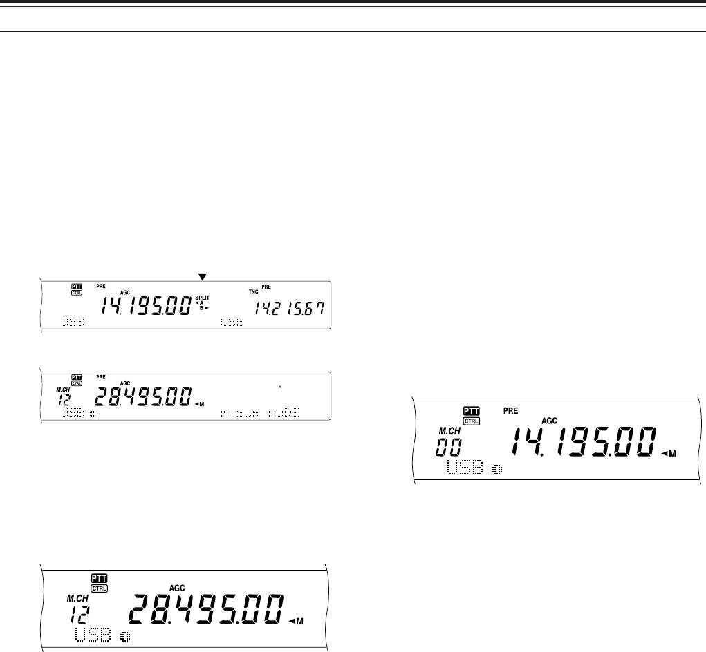
59
13 MEMORY FEATURES
■Split-Frequency Channels
1Press [A/B] to select VFO A or VFO B.
•“tA” or “tB” appears to show which VFO
is selected.
2Select the frequency, mode, etc. to be stored.
• This frequency and mode will be used for
transmitting.
3Press [A/B] to select the other VFO.
4Select the receive frequency and mode.
5Press [SPLIT].
• “SPLIT” appears.
6Press [M.IN] to enter Memory Scroll mode.
• To exit Memory Scroll mode and abort the
storage process, press [CLR].
7Turn the MULTI/ CH control, or press Mic [UP]/
[DWN] to select a memory channel.
• You can also select a channel by entering a
3-digit number, such as 012, using the
numeric keys.
8Press [M.IN] again to store the data.
• The previous data stored in the channel is
overwritten.
Note: When subtone frequencies differ between TX and RX
while performing memory-VFO split operation, the subtone
frequency for TX will be stored in the memory channel.
MEMORY RECALL AND SCROLL
There are two modes which allow you to retrieve
frequencies and associated data that you stored in a
memory channel: Memory Recall and Memory Scroll.
Memory Recall:
In this mode, the transceiver receives and transmits
using a frequency that you retrieve. You can
temporarily change the frequency and associated
data without overwriting the contents of the memory
channel when Menu No. 06B is set to ON.
Memory Scroll:
Use this mode to check the contents of the memory
channels without changing the current receive
frequency. In this mode, frequencies you retrieve are
not used for receiving and transmitting.
■Memory Recall
1Press [VFO/M] to enter Memory Recall mode.
• The memory channel that was last selected
appears.
2Turn the MULTI/ CH control, or press Mic [UP]/
[DWN] to select a memory channel.
• Continuously holding down Mic [UP]/
[DWN] steps the transceiver through the
memory channels until the key is released.
• Memory channels which contain no data are
skipped.
• You cannot change memory channels while
transmitting.
3To exit Memory Recall mode, press [VFO/M].
Note: Memory channels can also be changed while using the
TF-SET function.

60
13 MEMORY FEATURES
■Memory Scroll
1Press [M.IN] to enter Memory Scroll mode.
•The memory channel that was last selected
appears.
2Turn the MULTI/ CH control, or press Mic [UP]/
[DWN] to step through the memory channels.
• You can also change channels by entering a
3-digit number, such as 012, using the
numeric keys, then pressing [ENT].
3To exit Memory Scroll mode, press [CLR].
• The transceiver re-displays the memory
channel or VFO frequency that was
selected before you activated Memory
Scroll.
Note: Do not press [M.IN] again after entering Memory Scroll
mode. Pressing [M.IN] results in over-writing the current VFO
data to the memory channel you selected.
■Temporary Frequency Changes
After retrieving frequencies and associated data in
Memory Recall mode, you can temporarily change
the data without overwriting the contents of the
memory channel.
1Access Menu No. 06B and select ON.
• Skip this step when changing only the
associated data (not the frequency).
2Recall a memory channel.
3Change the frequencies and associated data.
• Use only the Tuning control to select a
frequency.
4If necessary for future use, store the changed
data in another memory channel. Refer to
“Channel ➡ Channel Transfer” {page 61}.
Note: Memory channel data can also be changed while using
the TF-SET function.
MEMORY-VFO SPLIT OPERATION
Under “ENHANCED COMMUNICATIONS” {page 31},
you learned about split-frequency operation using two
VFOs. Recalling a split-frequency channel is another
way to perform split-frequency operation. If you
access Menu No. 06A and select ON, you can also
use a memory channel and a VFO together for this
operation, as follows:
• RX: Memory channel
TX: VFO A or VFO B
• RX: VFO A or VFO B
TX: Memory channel
To use a memory channel for receiving:
1Access Menu No. 06A and select ON.
2Press [A/B] to select the VFO that you will use for
transmitting.
•“tA” or “tB” appears to show which VFO is
selected.
3Select the frequency for transmitting.
4Recall a memory channel by pressing [VFO/M].
5Turn the MULTI/ CH control to select a memory
channel to receive.
6Press [SPLIT].
7The VFO A frequency appears on the sub-display.
If you want to use the VFO B frequency to
transmit, press [SPLIT] again.
8Press [SEND] or Mic [PTT] to transmit on the
frequency shown on the sub display.
9Press [SPLIT] to exit the SPLIT operation.
• If Split operation is still selected using VFO A or
VFO B, press [SPLIT] again to exit Split
operation.
To use a memory channel for transmitting:
1Access Menu No. 06A and select ON.
2Recall a memory channel by pressing [VFO/M].
3Turn the MULTI/ CH control to select a memory
channel to transmit.
4Press [VFO/M] to return to VFO mode.
5Press [SPLIT]. The other VFO frequency appears
on the sub display for transmission (Normal SPLIT
operation).
6Press [SPLIT] again. The memory channel you
selected in step 3 appears on the sub-display for
transmission.
7Press [SEND] or Mic [PTT] to transmit on the
frequency in the memory channel.
8Press [SPLIT] to exit SPLIT operation.
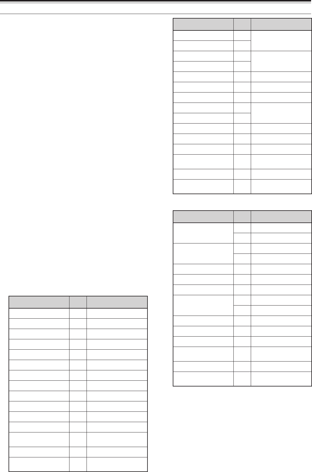
61
13 MEMORY FEATURES
MEMORY TRANSFER
■Memory \ VFO Transfer
After retrieving frequencies and associated data
from Memory Recall mode, you can copy the data
to the VFO. This function is useful, for example,
when the frequency you want to monitor is near
the frequency stored in a memory channel.
1Recall the desired memory channel.
2Press [Mss
ss
sVFO/ MG.SEL].
• When a simplex channel is recalled, the
data is copied to VFO A or VFO B,
depending on which VFO was used to recall
the channel.
• When a split channel is recalled, the RX
data is copied to VFO A and the TX data is
copied to VFO B.
Note:
◆
The Memory Channel Lockout status and the subtone
frequency are not copied.
◆
Pressing [M
ss
ss
s
VFO/ MG.SEL] after temporarily changing the
retrieved data copies the new data to the VFO.
■Channel \ Channel Transfer
You can also copy channel information from one
memory channel to another. This function is
useful when storing frequencies and associated
data that you temporarily change in Memory
Recall mode.
1Recall the desired memory channel {page 59}.
2Press [M.IN] to enter Memory Scroll mode.
• To exit Memory Scroll mode, press [CLR].
3Select the memory channel where you would
like the data copied, using the MULTI/ CH
control.
4Press [M.IN] again.
982~00lennahC a982~00lennahC
ycneuqerfXR aycneuqerfXR
ycneuqerfXT aycneuqerfXT
XRrofedoM aXRrofedoM
XTrofedoM aXTrofedoM
ycneuqerftesffO aycneuqerftesffO
noitceridtfihS anoitceridtfihS
FFO/NOesreveR aFFO/NOesreveR
petsycneuqerfXR apetsycneuqerfXR
petsycneuqerfXT apetsycneuqerfXT
ycneuqerfenoT aycneuqerfenoT
ycneuqerfSSCTC aycneuqerfSSCTC
edocSCD aedocSCD
SCD/SSCTC/enoT FFO/NO aSCD/SSCTC/enoT FFO/NO
emaNyromeM aemaNyromeM
lennahCyromeM FFO/NOtuokcoL alennahCyromeM FFOtuokcoL
982~00lennahC a992~092lennahC
ycneuqerfXR aycneuqerfXR/XT )xelpmis(
ycneuqerfXT a
XRrofedoM aXR/XTrofedoM )xelpmis(
XTrofedoM a
ycneuqerftesffO aycneuqerftesffO
noitceridtfihS anoitceridtfihS
FFO/NOesreveR aFFO/NOesreveR
petsycneuqerfXR aycneuqerfXR/XT )xelpmis(pets
petsycneuqerfXT a
ycneuqerfenoT aycneuqerfenoT
ycneuqerfSSCTC aycneuqerfSSCTC
edocSCD aedocSCD
SCD/SSCTC/enoT FFO/NO aSCD/SSCTC/enoT FFO/NO
emaNyromeM aemaNyromeM
lennahCyromeM FFO/NOtuokcoL alennahCyromeM FFOtuokcoL
992~092lennahC a982~00lennahC
ycneuqerfXR/XT aycneuqerfXR
aycneuqerfXT
XR/XTrofedoM aXRrofedoM
aXTrofedoM
ycneuqerftesffO aycneuqerftesffO
noitceridtfihS anoitceridtfihS
FFO/NOesreveR aFFO/NOesreveR
ycneuqerfXR/XT )xelpmis(pets
apetsycneuqerfXR
apetsycneuqerfXT
ycneuqerfenoT aycneuqerfenoT
ycneuqerfSSCTC aycneuqerfSSCTC
edocSCD aedocSCD
SCD/SSCTC/enoT FFO/NO aSCD/SSCTC/enoT FFO/NO
emaNyromeM aemaNyromeM
lennahCyromeM FFO/NOtuokcoL alennahCyromeM FFOtuokcoL
When copying a memory channel 290 ~ 299 a
channel 290 ~ 299, Memory Channel Lockout
status changes to OFF, regardless of the original
channel settings.
The tables above illustrate how data is transferred
between memory channels.
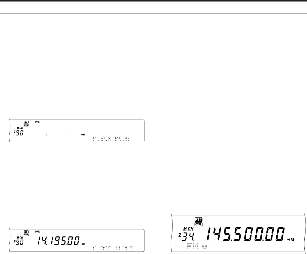
62
13 MEMORY FEATURES
STORING FREQUENCY RANGES
Memory channels 290 to 299 allow you to store
frequency ranges for VFO tuning and Program Scan.
Program Scan is described in the next chapter. To
tune or scan frequencies within a specified range,
store the start and end frequencies for that range in
advance.
1Press [A/B] to select VFO A or VFO B.
2Select the desired start frequency.
3Press [M.IN] to enter Memory Scroll mode.
• To exit Memory Scroll mode and abort the
storage process, press [CLR].
4Turn the MULTI/ CH control, or press Mic [UP]/
[DWN] to select a memory channel in the range of
290 to 299.
• You can also select a channel by entering a
3-digit number, such as 290, using the
numeric keys.
5Press [M.IN] to store the start frequency in the
memory channel.
• “CLOSE INPUT” appears on the sub dot-matrix
display.
6Turn the Tuning control or the MULTI/ CH control
to select the end frequency.
7Press [M.IN] to store the end frequency in the
memory channel.
• The previous data stored in the channel is
overwritten.
■Confirming Start/End Frequencies
Use this procedure to check the start and end
frequencies that you stored in channels 290 to 299.
1Press [VFO/M] to enter Memory Recall mode.
2Turn the MULTI/ CH control, or press Mic
[UP]/ [DWN] to select a memory channel from
290 to 299.
3Press [–] to check the start frequency and [+]
to check the end frequency.
■Programmable VFO
Using the start and end frequencies that you
stored in channels 290 to 299, Programmable
VFO restricts the frequency range that you can
tune with the Tuning control. One application of
this function is to help you operate within the
authorized frequency limits of your license.
1Press [VFO/M] to enter Memory Recall mode.
2Turn the MULTI/ CH control, or press Mic
[UP]/ [DWN] to select a memory channel from
290 to 299.
Now you can only tune from the start frequency to
the end frequency, using the Tuning control.
Note: Pressing Mic [UP]/ [DWN] or turning the MULTI/ CH
control results changing the memory channel number while in
Programmable VFO mode.
Memory Channel Lockout
You can lock out memory channels that you prefer
not to monitor during Memory Scan. Memory Scan is
described in the next chapter {page 68}.
1Press [VFO/M] to enter Memory Recall mode.
2Turn the MULTI/ CH control, or press Mic [UP]/
[DWN] to select the memory channel.
3Press [CLR] momentarily.
• Pressing [CLR] for more than approximately
2 seconds erases the contents of the
memory channel.
• A dot appears beside the right-most digit of the
memory channel number to indicate the
channel has been locked out.
• Repeatedly pressing [CLR] toggles between
adding and removing the channel from the
scan list.
ERASING MEMORY CHANNELS
If there are memory channels that you will not recall
in the future, you may prefer erasing the contents of
those channels.
1Press [VFO/M] to enter Memory Recall mode.
2Turn the MULTI/ CH control, or press Mic [UP]/
[DWN] to select the memory channel.
• You can also select a channel by entering a
3-digit number, such as 012, using the numeric
keys.
3Press and hold [CLR] for approximately two
seconds.
• A long beep sounds to confirm that the channel
data has been erased.
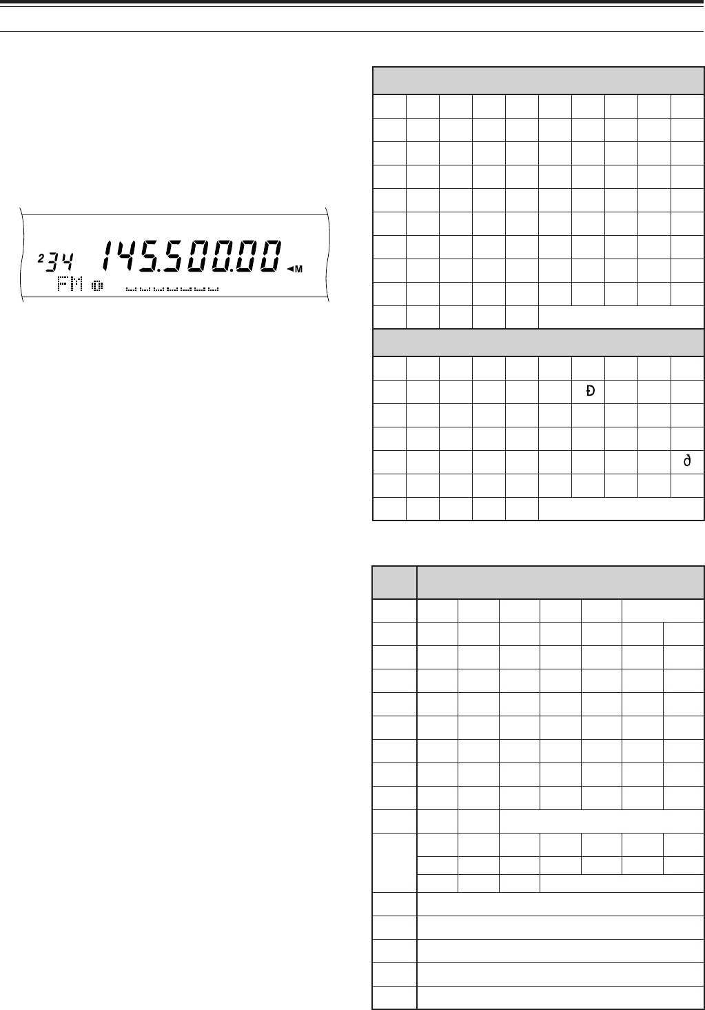
63
13 MEMORY FEATURES
MEMORY CHANNEL NAME
You can assign a name to each memory channel. A
maximum of 7 alpha-numeric characters can be
stored.
1Press [M.IN] to enter Memory Scroll mode.
2Turn the MULTI/ CH control, or press Mic [UP]/
[DWN] to select a memory channel.
3Press [DISP].
4Press [+]/ [–] or turn the MULTI/ CH control to
select the desired alpha-numeric character. You
can move the cursor to the left by pressing
[MAIN], or to the right by pressing [SUB]. Or, you
can use an optional DTMF microphone to enter
alpha-numeric characters.
Note: Alpha-numeric entries are limited to those characters
shown in the following DTMF character table when you are using
a DTMF Mic.
5After selecting all the necessary characters for the
memory channel name, press [M.IN] to store the
name, or press [DISP] to select a Memory Group.
You can select only one of 10 groups (0 to 9).
Enter the desired group number by pressing a
numeric key. The selected group is shown in a
larger font. After selecting a group, press [M.IN]
to store the name and group number in the
memory channel.
6When you recall a memory channel with a name,
the name is displayed on the dot-matrix display
along with the memory channel number and group
number {page 64}.
Alpha-numeric characters
ABCDEFGH I J
KLMNOPQRST
UVWXY Z [ \ ] ^
_`abcdefgh
i j k lmnopqr
stuvwxyz{ |
}~ PS!"#$%&’
()*+,–./01
23456789: ;
<=>?@
ÀÁÂÃÄÅÆÇÈÉ
ÊËÌÍÎÏ ÑÒÓ
ÔÕÖ ØÙÚÛÜ
ߌàáâãäåæ
çèéêëìíîï
ñòóôõöœøùú
ûü Ÿÿ
´
y
ˆ
S
´
Y
ˆ
s
Additional characters for all E-types
Available characters
Available characters using a DTMF Mic
FMTD yek sretcarahcelbaliavA
1qz1QZ
2abc2ABC
3def3DEF
4ghi4GHI
5jkl5JKL
6mno6MNO
7 p r s 7PRS
8 tuv8TUV
9wxy9WXY
0ecaps0
#
?! ' .,–/
&# ( ) <> ;
:"@
*noitcnufoN
AthgirrosrucehtevoM
BtfelrosrucehtevoM
CretcarahcdetcelesehteteleD
DsaemaS ]NI.M[]NI.M[ ]NI.M[ ]NI.M[]NI.M[ yek
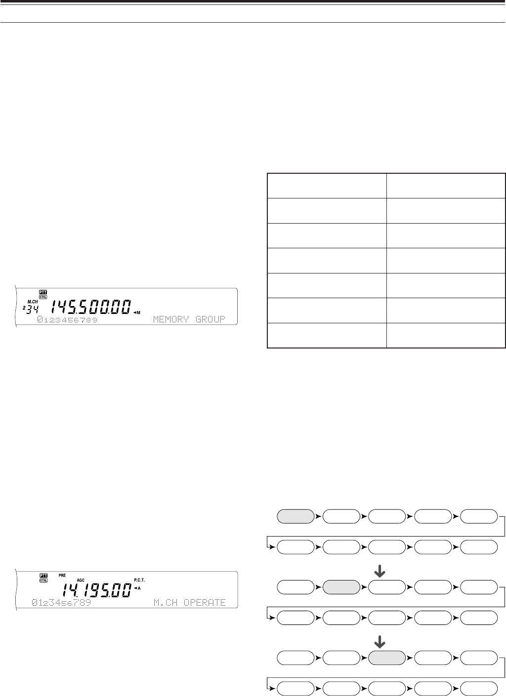
64
13 MEMORY FEATURES
MEMORY GROUP
To manage 300 memory channels, you can divide
them up into a maximum of 10 groups (Groups 0 to 9).
After you configure a Memory Group, you can select
one or more of the Memory Groups you want to recall,
in Memory Recall mode. As a default, all memory
channels are stored in Group 0.
To change the Memory Channel Group:
1Press [M.IN] to enter Memory Scroll mode.
2Select the desired memory channel for which you
want to change the Memory Group by turning the
MULTI/ CH control.
3Press [DISP].
• The Memory Name input prompt appears.
4Press [DISP] again to skip the input or enter a
Memory Name using [+]/ [–] and [MAIN] or [SUB]
{page 63}.
• The current Memory Group appears in a larger
font.
5Press a numeric key to change the selected
Group number. The newly selected Group
number appears in a larger font.
6Press [M.IN] to store the settings.
■Memory Group Select
After you configure Memory Groups to the Memory
Channels, you can select one or more of the Groups
to be recalled in Memory Recall mode.
To select Memory Groups:
1Press [FUNC], [Mss
ss
sVFO/ MG.SEL] to enter
Memory Group Select mode.
2Numbers 0 ~ 9 appear in the main dot-matrix
display. The selected Memory Group numbers are
displayed in larger fonts. To change the selection,
press a numeric key. To select all the Memory
Groups, press [•/ DCS/SEL]. At least, one
Memory Group must be selected.
3Press [M.IN] to save the setting and exit.
4You can now recall only the selected Memory
Groups in Memory Recall mode.
QUICK MEMORY
Quick memory is designed to quickly and temporarily
save data without specifying a particular memory
channel. Use Quick memory to store data you will
not use in future operating sessions. For example, as
you tune across the band looking for DX, it is
convenient to store stations that you want to contact.
You can quickly jump between several different
memory channels as you monitor them.
This transceiver provides ten Quick memory channels
(“0_” to “9_”) that can store the following data:
dnaycneuqerfAOFV edomgnitarepo dnaycneuqerfBOFV edomgnitarepo
FFO/NOreviecer-buS ycneuqerfreviecer-buS edomgnitarepodna
FFO/NOTIRFFO/NOTIX
ycneuqerftesffoTIX/TIRhtdiwdnabretlifrevieceR
FFO/NOreknalBesioNFFO/NOENIF
noitcudeResioNPSD 2/1/FFO lecnaCtaeBPSD FFO/NO
hctoNotuAPSD FFO/NO snoitcnufXR/XT
STORING INTO QUICK MEMORY
Each time you store a new frequency, all previously
stored frequencies are bumped to the next respective
Quick memory channel. When all ten memory
channels contain frequencies, storing one more
frequency bumps the contents of memory channel 9
off the stack (the data is lost).
The following diagram illustrates how the Quick
Memory stacks the data in memory each time you
press QUICK MEMO [M.IN].
24.911
Memory 0
144.005
Memory 1
14.235
Memory 2
441.250
Memory 3
18.111
Memory 4
50.015
Memory 5
7.082
Memory 6
29.610
Memory 7
3.545
Memory 8
145.250
Memory 9
21.005
Memory 0
24.911
Memory 1
144.005
Memory 2
14.235
Memory 3
441.250
Memory 4
18.111
Memory 5
50.015
Memory 6
7.082
Memory 7
29.610
Memory 8
3.545
Memory 9
14.085
Memory 0
21.005
Memory 1
24.911
Memory 2
144.005
Memory 3
14.235
Memory 4
441.250
Memory 5
18.111
Memory 6
50.015
Memory 7
7.082
Memory 8
29.610
Memory 9
New data
New data
New data
Note: To use the Quick memory channels, you must operate both
the main transceiver and the sub-receiver in VFO mode. If you are
using the Quick memory channels while the sub-receiver is turned
off, its last operating mode must be VFO mode. Turning the
sub-receiver off while it is recalling a memory channel will not allow
you to use the Quick memory function.

65
13 MEMORY FEATURES
You can store data in the Quick Memory only when
you operate both the main transceiver and the
sub-receiver in VFO mode.
1Select the frequency, mode, etc. on the main
transceiver or sub-receiver VFO.
2Press QUICK MEMO [M.IN].
• Each time QUICK MEMO [M.IN] is pressed,
the current VFO data is written to the Quick
Memory.
Note: When RIT or XIT is ON, this ON status and the offset will
also be stored.
RECALLING QUICK MEMORY CHANNELS
You can recall a Quick Memory channel only when
you operate both the main transceiver and the
sub-receiver in VFO mode.
1Press QUICK MEMO [MR].
• The current memory channel number appears.
• If there is no data stored in any Quick memory
channel, the data cannot be recalled to the
current VFO, an error beep sounds.
2Turn the MULTI/ CH control to select a Quick
memory channel (0 to 9).
• You cannot change memory channels while
transmitting.
3To exit, press QUICK MEMO [MR] again.
Note: Memory channels cannot be changed while using the
TF-SET function.
TEMPORARY FREQUENCY CHANGES
After recalling a Quick memory channel, you can
temporarily change the data without overwriting the
contents of the channel. You can change the
frequency even when you select OFF in Menu
No. 06B.
1Press QUICK MEMO [MR].
2Turn the MULTI/ CH control to select a Quick
memory channel (0 to 9).
3Change the frequencies and associated data.
4To store the changed data in the Quick memory,
press QUICK MEMO [M.IN].
•This action stores the new data in the current
channel and bumps the old frequency to the
next higher Quick memory channel.
5To exit, press QUICK MEMO [MR] again.
Note: Memory channel data can also be changed while using
the TF-SET function.
QUICK MEMORY ➡ VFO TRANSFER
This function copies the contents of the recalled
memory channel to the VFO.
1Recall a Quick Memory channel.
2Press [Mss
ss
sVFO/ MG.SEL].
Note: Pressing [M
ss
ss
s
VFO/ MG.SEL] after temporarily changing the
recalled data copies the new data to the VFO.
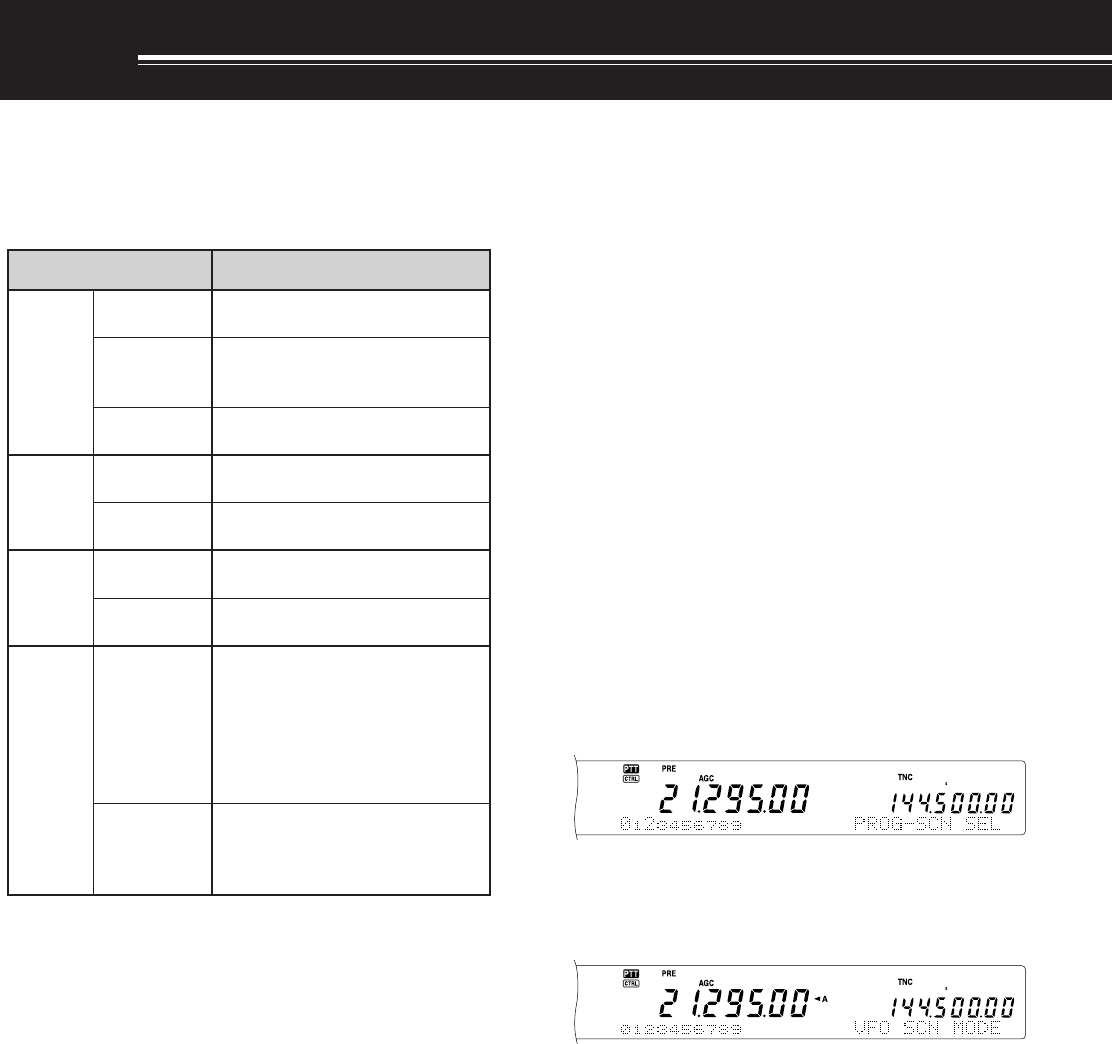
66
SCAN
Scan is a useful function for hands-off monitoring of
your favorite frequencies. By becoming comfortable
with all types of Scan, you will increase your operating
efficiency.
This transceiver provides the following types of scans.
epyTnacS esopruP
lamroN nacS
nacSOFV ehtfodnaberitneehtsnacS detcelesuoyycneuqerf
margorP nacS
ycneuqerfcificepsehtsnacS yromeMniderotssegnar 992~092slennahc
nacSzHM nihtiwseicneuqerfehtsnacS egnarzHM1a
yromeM nacS
lennahC-llA nacS ,slennahcyromeMllasnacS 992ot00morf
nacSpuorG yromeMcificepsehtsnacS spuorglennahc
llaC nacS
OFV dnalennahcllaCehtsnacS ycneuqerfOFVtnerruceht
yromeM lennahC dnalennahcllaCehtsnacS lennahcyromeMdetceleseht
lausiV *nacS
OFV
gnitarepotnerrucehtsnacS asallewsaycneuqerf forebmundeificeps wolebdnaevobaseicneuqerf langisehT.ycneuqerftaht silennahchcaefohtgnerts hparg-rabanideyalpsid
yromeM lennahC
slennahcyromeMehtsnacS langisehtsyalpsiddna anilennahchcaefohtgnerts hparg-rab
*Visual Scan graphically shows how frequencies in a specific range
are busy.
Note:
◆
While using CTCSS or DCS, Scan stops only for the signals that
contain the same CTCSS tone or DCS code that you selected.
◆
When using S-meter Squelch, Scan stops when the received
signal strength matches or exceeds the S-meter setting. Scan
resumes 2 seconds after the signal level drops below the S-meter
setting.
◆
Pressing and holding Mic [PTT] causes Scan to stop if it is
functioning on a non TX band. Pressing Mic [PTT] on the
scanning band causes Scan to stop.
◆
Starting Scan switches OFF the Automatic Simplex Checker.
NORMAL SCAN
When you are operating the transceiver in VFO mode,
2 types of scanning are available.
• VFO Scan
The transceiver scans the entire band of the
frequency you selected. For example, if you are
operating and receiving on the main transceiver’s
VFO A at 14.195.00 MHz, it scans all the
frequencies in the range of 30.00 kHz to
60.00000 MHz. (Refer to VFO frequency range
in the Specifications.)
• Program Scan
By programming the start and end frequency in
Memory channels 290 ~ 299 {page 62}, you can
limit the scanning frequency range. Since there
are 10 memory channels (290 ~ 299) available for
specifying the start and end frequency, you can
select one or more (a maximum of 10) ranges to
scan. This is useful when you are waiting for a DX
station on a certain frequency but the station may
appear on slightly higher or lower frequency.
VFO SCAN
VFO Scan scans the entire frequency range that is
available for the current VFO. When the Program
Scan frequency range is not programmed or no Scan
Group is selected for the Program Scan, the
transceiver also scans the entire frequency range
available for the current VFO.
If one or more Program Scan frequency ranges are
programmed in memory channels 290 to 299:
1Press [FUNC], [SCAN/ SG.SEL].
2If one or more memory channels are selected for
the Program Scan, the selected channels are
displayed in a larger font on the main dot-matrix
display.
In this case, press [•/ DCS/SEL] to temporarily
deselect all the channels. When there are no Scan
Group channels selected, “VFO SCN MODE”
appears on the sub dot-matrix display.
3Press [SCAN/ SG.SEL] to return to the current
VFO mode.
4Press [SCAN/ SG.SEL] to start the VFO Scan.
Note:
◆
While scanning, you can change the scan speed by turning the
RIT/ SUB control. Turn the control clockwise/ counterclockwise
to decrease/ increase the scan speed. The speed indicator
appears on the main dot-matrix display, where P1 is the fastest
speed and P9 is the slowest.
◆
You cannot change the VFO Scan speed in FM mode.
◆
You cannot change the VFO Scan speed on the sub-receiver.
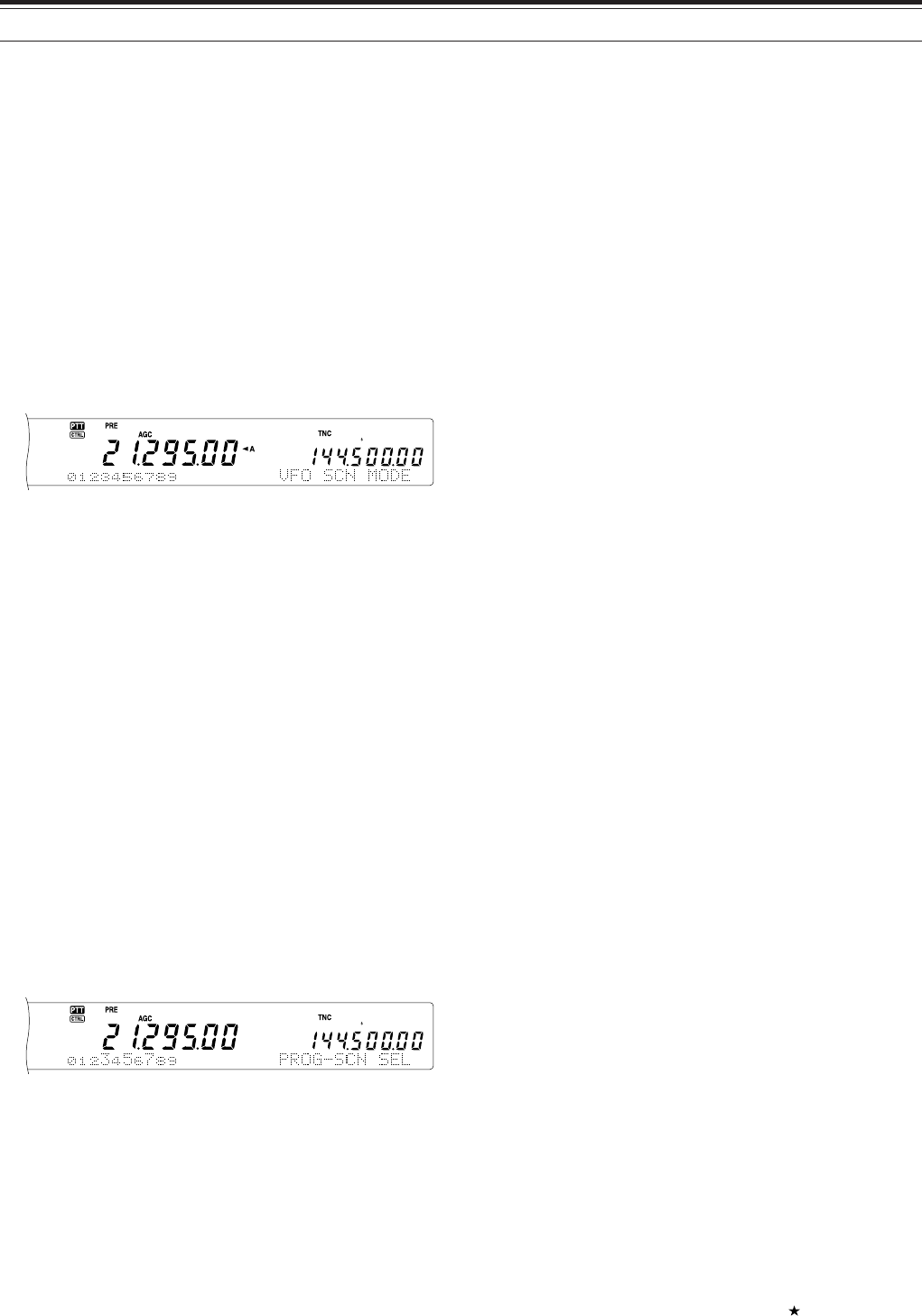
67
14 SCAN
PROGRAM SCAN
Program Scan monitors the range between the start
and end frequencies that you have stored in
Conventional memory channels 290 to 299. Refer to
“STORING FREQUENCY RANGES” {page 62} for
details on how to store the start and end frequencies.
You can select a maximum of 10 memory channels
(Memory channels 290 to 299) and sequentially scan
the ranges that you stored in these channels. Program
Scan starts with the smallest channel number and
repeats the sequence as described below.
1Press [A/B] to select VFO A or VFO B.
• If you are operating the sub-receiver, press
[VFO/M] to select VFO mode.
2Press [FUNC], [SCAN/ SG.SEL].
3If no Program scan channel is selected, all memory
channel numbers (from 290 to 299) are displayed in
small fonts. Only the one’s digit of each memory
channel is displayed on the main dot-matrix display.
0 represents channel 290, 1 represents channel 291,
2 represents channel 292, etc.
4To select the Program scan frequency range,
press a numeric key 0 to 9. For example, press
[3] for channel 293 only or press [3], [5], [7] to
select channels 293, 295, and 297. When a
channel is selected for the Program Scan, the
number is displayed in a larger font.
To temporarily deselect all the channels (290 to 299)
so that you can perform the VFO Scan, press
[•/ DCS/SEL] (Refer to “VFO SCAN” on page 66).
Note:
◆
At least one of the valid Program Scan channels (from 290 to 299)
must be programmed and selected to perform the Program Scan.
If no Program channel is selected or available for the Program
Scan, the transceiver performs the VFO Scan.
◆
When performing the Program Scan on the sub-receiver, the
frequencies must be within the sub-receiver frequency range
limitations. Otherwise, the Program Scan cannot be performed.
The same conditions apply to the main transceiver.
5Press [SCAN/ SG.SEL] to start the Program
Scan.
• To quickly move towards a desired frequency
while scanning, turn the Tuning control or the
MULTI/ CH control, or press Mic [UP]/ [DWN].
• When in a mode other than FM mode, turning
the RIT/ SUB control clockwise decreases the
scan speed, and counterclockwise increases
the speed. The current scan speed is shown
on the display; P1 is the fastest speed and P9
is the slowest.
• While in FM mode, Scan automatically stops
on a frequency where a signal is present. The
transceiver will either remain on that channel
for a short time (Time-operated mode) or until
the signal drops out (Carrier-operated mode),
depending on which mode you select via Menu
No. 10 {page 68}.
6To stop Scan, press [SCAN/ SG.SEL] or [CLR].
Note:
◆
If you are operating on the sub-receiver and perform the Program
Scan, the sub-receiver automatically skips the memory channels
that cannot be scanned on the sub-receiver. The same
conditions also apply to the main transceiver.
◆
If you have turned the MAIN SQL or SUB SQL control clockwise,
far beyond the squelch threshold when in FM mode, Scan may
fail to stop at a channel where a signal is present. If this
happens, turn the MAIN SQL or SUB SQL control slightly
counterclockwise.
◆
If you press [SCAN/ SG.SEL] before storing any frequency range
for memory channels 290 to 299, the transceiver starts VFO
scan.
◆
When the current receive frequency is within one of the ranges
that you selected with channel numbers, Scan starts with the
current frequency. The operating mode stored in the memory
channel is used.
◆
When the current receive frequency is outside all the ranges that
you selected with the channel numbers, Scan starts with the start
frequency stored in the smallest channel number.
◆
The operating mode can be changed while scanning, but the
memory channel is overwritten with the changed mode.
◆
When the current Scan range is smaller than a single step of the
MULTI/ CH control, turning the control clockwise causes Scan to
jump to the start frequency, and counterclockwise to the end
frequency.
◆
Starting Program Scan switches OFF the RIT and XIT functions.
◆
While in FM mode, the Program Scan monitors rounded off
frequencies regardless of the Menu No. 04 setting.
◆
You cannot change the scan speed on the sub-receiver.
PROGRAM SCAN PARTIALLY SLOWED
You can specify a maximum of 5 frequency points for
each memory channel from 290 to 299 so that the
Program Scan slows down the scanning speed. To
specify the slow down frequency points, first program
the start and end frequencies into a memory channel
(290 ~ 299) {page 62}.
1Access Menu No. 07 to confirm that the function is
ON (default is ON).
2You can further configure the slow down frequency
width. Access Menu No. 08 to select the range
from 100 Hz to 500 Hz (default is 300 Hz).
Note: If you select, for example, 500 Hz for Menu No. 08, the
Program Scan slows down to a
±
500 Hz width, centering the
frequency you marked below.
3Press [VFO/M] to recall the memory channel
(290 ~ 299) for which you want to specify the
scan slow down frequencies.
4Press [–]/ [+] to confirm the start ([–]) or end ([+])
frequency.
5Turn the Tuning control to the center frequency
point that you want the Program Scan to slow
down. Press QUICK MEMO [M.IN] to mark the
Slow down frequency point. The “ ” icon appears.

68
14 SCAN
6Repeat step 5 to specify the center slow down
frequency points. You can specify a maximum of
5 frequency points for each channel.
7If you want to clear the slow down frequency
points that you previously stored, press and hold
QUICK MEMO [M.IN] for 1 second.
A confirmation beep sounds and the transceiver
clears all the slow down frequency points you
specified in the memory channel.
Note: You must clear all the previous slow down frequency
points; you cannot clear only specific points.
8Press [VFO/M] to return to VFO mode.
9Press [SCAN/ SG.SEL] to start the Program Scan
with the slow down frequency point(s).
Note:
◆
During the Program Scan, you can turn the RIT/ SUB control to
adjust the scanning speed. Turn the control clockwise/ counter-
clockwise to slow down/ speed up the scan. The Program Scan
speed indicator appears on the main dot-matrix display during
the Program Scan; P1 is the fastest speed and P9 is the slowest.
◆
You cannot change the Program Scan speed in FM mode.
◆
You cannot change the scan speed on the sub-receiver.
◆
You cannot specify the Program Scan slow down frequency point
for FM mode.
SCAN HOLD
This function stops Program Scan for approximately
5 seconds, then resumes Scan when you jump to the
desired frequency by turning the Tuning control or the
MULTI/ CH control, or by pressing Mic [UP]/ [DWN].
To use this function, access Menu No. 09, and select
ON. The default is OFF.
MHz SCAN
When you operate the main transceiver or sub-
receiver in VFO mode, you can scan an entire 1 MHz
frequency range within the current VFO frequency.
1Press [VFO/M] to select VFO mode.
2Select the desired frequency to perform the MHz
Scan. If you want to scan the entire 145 MHz
frequency, for example, select 145.650 MHz.
Scan will operate between 145.00000 MHz and
145.99999 MHz.
3Press and hold [1MHz/ SEL] to start the MHz Scan.
4Turn the RIT/ SUB control to adjust the scan
speed.
5To stop the MHz Scan, press [SCAN/ SG.SEL] or
[CLR].
Note:
◆
You cannot change the MHz Scan speed in FM mode.
◆
You cannot change the scan speed on the sub-receiver.
MEMORY SCAN
Memory Scan monitors all memory channels in which
you have stored frequencies (All-channel Scan) or only
a desired group of memory channels (Group Scan).
Scan automatically stops at a channel where a signal
is present, regardless of the operating mode. The
transceiver will either remain on that channel for a
short time (Time-operated mode) or until the signal
drops out (Carrier-operated mode). Use Menu No. 10
to select either mode. The default is Time-operated.
SCAN RESUME METHOD
The transceiver stops scanning at the frequency (or
memory channel) where a signal is detected. It then
continues scanning according to which resume mode
you have selected. You can choose one of the
following modes. The default is Time-operated mode.
• Time-Operated mode
The transceiver remains on a busy frequency (or
memory channel) for approximately 6 seconds,
then continues to scan, even if the signal is still
present.
• Carrier-Operated mode
The transceiver remains on the busy frequency (or
memory channel) until the signal drops out. There
is a 2 second delay between signal dropout and
scan resumption.
1Press [MENU] to enter Menu mode.
2Turn the MULTI/ CH control to select Menu No. 10.
3Press [+]/ [–] to select TO (Time-Operated) or CO
(Carrier-Operated).
4Press [MENU] to complete the setting and exit
Menu mode.
You can lock out the memory channels that you
prefer not to monitor while scanning. To do this, refer
to “Memory Channel Lockout” {page 62}.
ALL-CHANNEL SCAN
Use the following procedure to scan all the memory
channels that contain frequency data in sequence,
ignoring the Memory Group number.
1Select Time-operated or Carrier-operated mode
via Menu No. 10.
2Press [VFO/M] to enter Memory Recall mode.
3Turn the MAIN SQL or SUB SQL control to adjust
the squelch threshold.
4Press [FUNC], [SCAN/ SG.SEL] to enter Scan
Group Select mode.
• The selected Groups appear in a larger font.
5Press [•/ DCS/SEL] to deselect all Groups so that
the transceiver scans the memory channel
sequentially, ignoring the Memory Group number
data.

69
14 SCAN
6Press [SCAN/ SG.SEL] to return to Memory
Recall mode.
7Press [SCAN/ SG.SEL] to start All-channel Scan.
• Scan starts from the current memory channel
and ascends up through the channel numbers
(scan direction cannot be changed).
• To jump to a desired channel while scanning,
turn the MULTI/ CH control, or press Mic
[UP]/ [DWN].
8To stop Scan, press [SCAN] or [CLR].
Note:
◆
If you are operating on the sub-receiver and perform the Memory
Scan, the transceiver automatically skips the memory channels
that cannot be received by the sub-receiver. The same
conditions apply to the main transceiver.
◆
If you have turned the MAIN SQL or SUB SQL control clockwise,
far beyond the squelch threshold, Scan may fail to stop at a
channel where a signal is present. If this happens, turn the SQL
control slightly counterclockwise.
◆
Starting Memory Scan switches OFF the RIT and XIT functions.
GROUP SCAN
For the purpose of Group Scan, the 300 memory
channels can be divided into 10 groups so that you
can select one or more groups to be scanned,
depending on the situation.
When you store frequency data in a memory channel
{page 58}, the transceiver automatically adds the
default Group 0 (zero), to the memory channel data.
To recall the existing memory channel data and
revise the Group number:
1Press [M.IN] to enter Memory Scroll mode.
2Select the desired memory channel by turning the
MULTI/ CH control.
3Press [DISP].
• The Memory Name input prompt appears.
Press [DISP] again to skip the input or enter a
Memory Name using [+]/ [–] and [MAIN] or
[SUB] {page 63}.
4Press the desired Group number ([0] to [9]) using
the numeric keypad. The selected Group number
appears in a larger font.
Note: You can select only one of 10 groups (0 to 9) for each
memory channel.
5Press [M.IN] to store and overwrite the new
channel data to the memory channel.
6Repeat steps 2 through 6 for each memory
channel you want to assign to a specific group.
You can select a maximum of 10 groups and
sequentially scan the channels that belong to those
groups. Group Scan starts with the smallest group
number and repeats the sequence, for example,
group 3 ➞ group 5 ➞ group 7 ➞ group 3.
1Select Time-operated or Carrier-operated mode
via Menu No. 10.
2Press [VFO/M] to enter Memory Recall mode.
3Turn the MAIN SQL or SUB SQL control to adjust
the squelch threshold.
4Press [FUNC], [SCAN/ SG.SEL] to enter Scan
Group Select mode. Then, using the numeric
keypad, enter the group numbers you want to
scan. i.e.- Press [3] for group 3, or press [3], [5],
[7] for groups 3, 5, and 7. The selected Memory
Groups appear in a larger font.
5Press [SCAN/ SG.SEL] to exit Scan Group Select
mode.
6Press [SCAN/ SG.SEL] again to start Memory
Group Scan.
• Scan ascends up through the channel numbers
(scan direction cannot be changed).
• To jump to a desired channel while scanning,
turn the MULTI/ CH control or press Mic
[UP]/ [DWN].
7To stop Scan, press [SCAN/ SG.SEL] or [CLR].
After using Group Scan, press [FUNC],
[SCAN/ SG.SEL], then [•/ DCS/SEL] to deselect all
the Group numbers you selected in step 4. This
returns you to All-channel Scan (factory default).
Note:
◆
If you are operating on the sub-receiver and perform the Group
Scan, the transceiver automatically skips the memory channels
that cannot be received by the sub-receiver. The same
conditions apply to the main transceiver.
◆
If you have turned the MAIN SQL or SUB SQL control clockwise,
far beyond the squelch threshold, Scan may fail to stop at a
channel in which a signal is present. If this happens, turn the
SQL control slightly counterclockwise.
◆
When the current channel is within one of the groups that you
selected, Scan starts with the current channel.
◆
When the current channel is outside all the groups that you
selected, Scan starts with the group number that is larger than
and closest to the group number of the current channel.
◆
Starting Memory Scan switches OFF the RIT and XIT functions.
CALL SCAN
A Call channel can be stored for each operating
band, such as HF, 50 MHz, 144 MHz, 430/ 440 MHz
and 1.2 GHz (TS-2000 Optional) bands. You can
monitor one of these Call channels and the current
operating frequency alternatively.
1Select the frequency you want to monitor.
• In VFO mode, press [A/B] to select VFO A or B
for the main transceiver or press [SUB] or
[CTRL] to select the sub-receiver VFO. Then,
turn the Tuning control or the MULTI/ CH
control to select the desired frequency.
• In Memory Recall mode, press [VFO/M] to
select the memory channel you want to monitor
by turning the MULTI/ CH control.
2Press [CALL/ C.IN] to recall the Call channel for
the frequency band.
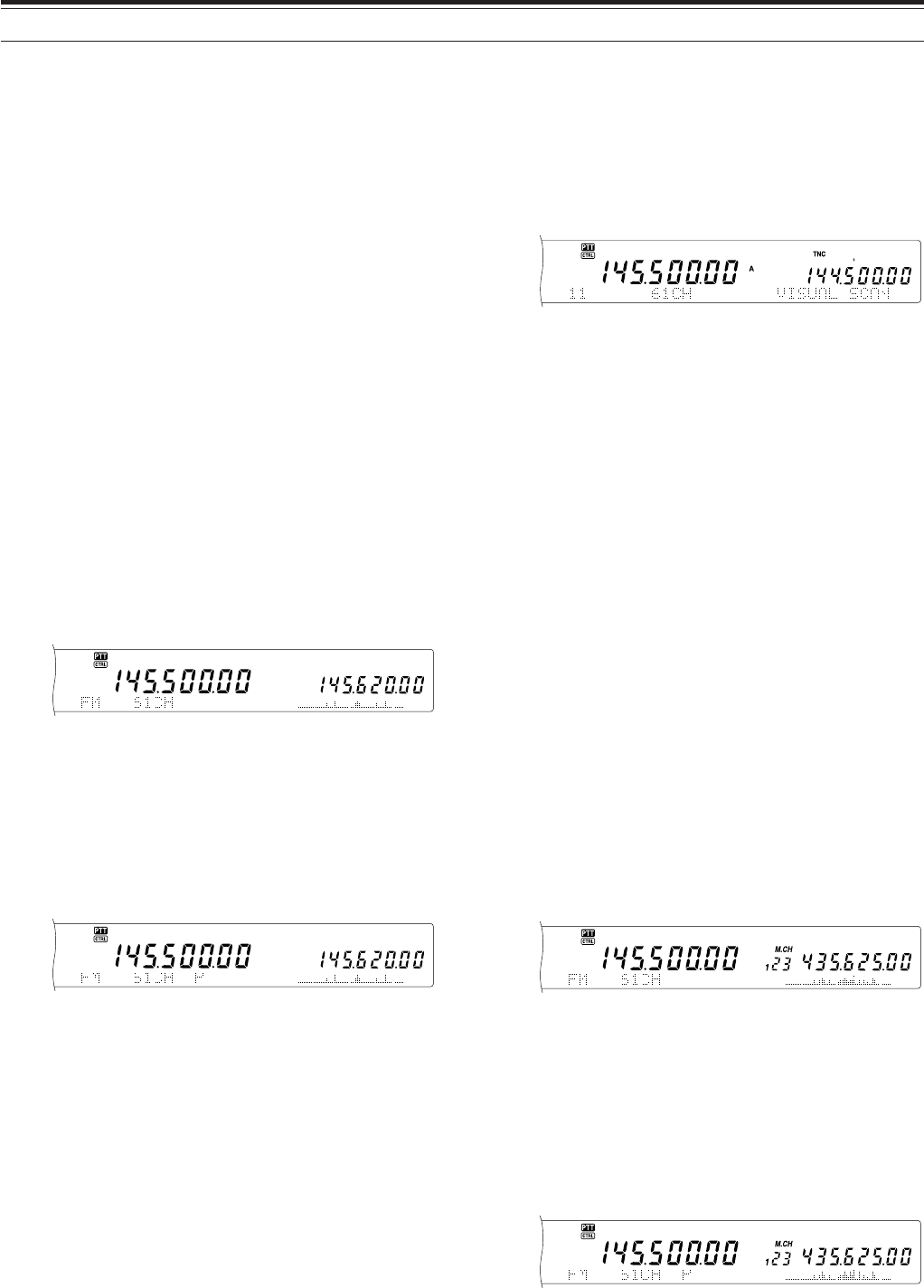
70
14 SCAN
3Press [SCAN/ SG.SEL].
4The Call channel and the selected VFO frequency
or memory channel are monitored alternatively.
5To stop Scan, press [SCAN/ SG.SEL] or [CLR].
VISUAL SCAN
While you are receiving, Visual Scan allows you to
monitor frequencies near the current operating
frequency. Visual Scan graphically displays how all
frequencies in the selected range are busy. You will
see a maximum of 7 segments, for each frequency
(channel) point that represent relative S-meter levels.
Determine the scan range by selecting the center
frequency and the number of channels. The default
number of channels is 61.
■Using Visual Scan (VFO)
1Select the desired band for Visual Scan.
2Turn the Tuning control, or press Mic [UP]/
[DWN], to select the operating frequency.
• This frequency will be used as the center
frequency.
3Press and hold [DISP] for approximately
1 second to start Visual Scan (VFO).
• The center frequency is displayed on the
main frequency display and the current
scanning frequency is displayed on the sub
frequency display. The operating mode and
the number of channels to be scanned are
displayed on the main dot-matrix display.
The sub dot-matrix display shows the
relative S-meter level of each frequency
point, vertically.
• To pause Scan, press [DISP]. “P” appears
on the main dot-matrix display. While the
Visual Scan is paused, you can monitor the
paused frequency. Press [DISP] again to
resume the Visual Scan.
4To change the current scanning frequency, turn
the Tuning control or press Mic [UP]/ [DWN].
• The displayed frequency changes and the
cursor moves.
• Press [1MHz/ SEL] to make the current
scanning frequency the new center
frequency.
• You can move the frequency using the Tuning
control. If you want to revert to the original
center frequency, press [FM/ AM/ NAR].
5To quit Visual Scan, press [CLR] or
[SCAN/ SG.SEL].
■Changing the Number of Channels to Scan
1Press [MENU] to enter Menu mode.
2Turn the MULTI/ CH control to select Menu
No. 11.
3Press [+]/ [–] to select 31, 61 (default), 91 or
181 channels for the number of channels to
scan.
4Press [MENU] to exit Menu mode.
Note:
◆
The current frequency step of the MULTI/ CH control is used
for the Visual Scan.
◆
While performing the Visual Scan, the DUAL WATCH
function {page 47} is temporarily disabled unless you are
using the 144 MHz or 430/ 440 MHz in FM or AM mode and
the Control Band for the main transceiver.
◆
If you start the Visual Scan from the frequency on the sub-
receiver, the frequency is transferred to the main display,
then the Visual Scan starts.
◆
If you start the Visual Scan in Memory Recall mode, the
memory channel frequencies will be scanned.
◆
Visual Scan stops when you transmit.
◆
Depending on the transceiver conditions, Visual Scan and
the S-meter level may differ.
■Using Visual Scan (Memory Channel)
1Press [MENU] to enter Menu mode.
2Turn the MULTI/ CH control to select Menu
No. 11.
3Press [+]/ [–] to select 31, 61 (default), 91 or
181 channels for the number of channels to
scan.
4Press [VFO/M] to enter Memory Recall mode.
5Press and hold [DISP] for approximately
1 second to start Visual Scan (Memory
Channel).
• The center memory channel number is
displayed on the main frequency display
and the current scanning frequency is
displayed on the sub frequency display.
The operating mode of the center memory
channel and the number of channels to be
scanned are displayed on the main dot-
matrix display. The sub dot-matrix display
shows the relative S-meter level of each
frequency point, vertically.
• To pause Scan, press [DISP]. “P” appears
on the main dot-matrix display. While the
Visual Scan is paused, you can monitor the
paused frequency. Press [DISP] again to
resume the Visual Scan.

71
14 SCAN
6To change the current scanning frequency,
turn the MULTI/ CH control or press Mic
[UP]/ [DWN].
• The displayed memory channel number
changes and the cursor moves.
• Press [1MHz/ SEL] to make the current
scanning frequency the new center
scanning channel.
7To quit Visual Scan, press [CLR] or
[SCAN/ SG.SEL].
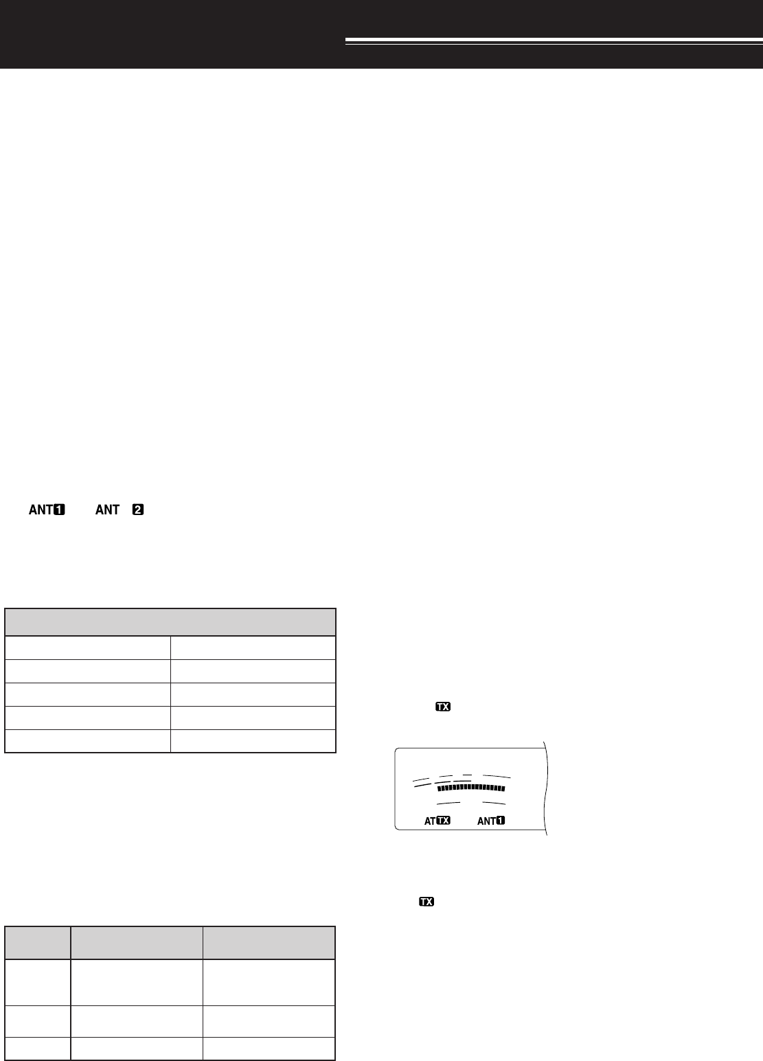
72
OPERATOR CONVENIENCES
APO (Auto Power OFF)
You can set the TS-2000(X) to switch OFF
automatically if no keys or controls are pressed or
adjusted for a certain period of time. 1 minute before
the transceiver switches OFF, “CHECK” is output in
Morse code. You can select the time from OFF, 60,
120, and 180 minutes.
Press [MENU], then turn the MULTI/ CH control to
access Menu No. 57.
Select the APO time from OFF, 60, 120, or 180
minutes.
Note:
◆
The APO function works even if the transceiver is scanning.
◆
The APO timer starts counting down the timer when no key
presses, no control adjustments, and no command (RS-232C
port) sequences are detected.
AUTOMATIC ANTENNA TUNER
As explained in “ANTENNA CONNECTION” {page 1},
matching the impedance of the coaxial cable and
antenna is important. To adjust the impedance
between the antenna and the transceiver, you have
the choice of using the internal tuner or an external
tuner. This section describes how to use the internal
tuner. For the external tuner, consult the instruction
manual that comes with the tuner.
1Select the transmit frequency.
2Press [FUNC], [AT/ ANT1/2] to select ANT 1 or
ANT 2.
• If an external tuner is connected to the ANT 1
connector, select ANT 2 to use the internal
antenna tuner. The internal antenna tuner is
automatically bypassed if an external antenna
tuner is connected to ANT 1.
3Press [AT/ ANT1/2] momentarily.
•“AT” appears, indicating that the internal
tuner is in-line (not bypassed).
F
I
L
T
E
R
S
1
3
5
7
9
2
0
4
0
6
0
d
B
P
W
R
1
0
2
5
5
0
1
0
0
W
%
A
L
C
4Press [AT/ ANT1/2] for more than one second.
• CW mode is selected and tuning begins.
•“” blinks and the MAIN band LED lights red.
• To cancel tuning, press [AT/ ANT1/2] again.
• If the SWR of the antenna system is extremely
high (more than 10:1), an alarm (“SWR” in
Morse code) sounds and the internal tuner is
bypassed. Before attempting to tune again,
adjust the antenna system to lower the SWR.
5See the display and check that tuning has
successfully finished.
ALT (Auto Lock Tuning)
The ALT (Auto Lock Tuning) allows the transceiver to
adjust the center receiving frequency automatically
when you operate on the 1.2 GHz band in FM mode.
When the receiving audio signal is distorted or breaking
up, turn this function on to adjust the center receiving
frequency. Some old 1.2 GHz transceivers do not have
stable and precise oscillating circuits and tend to be
slightly off (drifted from) the displayed frequency.
Press [FUNC], [XIT/ ALT] to toggle between the ALT
function ON or OFF.
• “ALT” appears when the function is ON.
Note: The ALT (Auto Lock Tuning) works only on the 1.2 GHz band
in FM mode.
ANTENNAS
HF/ 50 MHz Band
Two antenna connectors are available for the HF/
50 MHz band on the rear panel {page 13}. When you
operate the main transceiver on these frequencies,
you can select one of 2 antennas.
Press [FUNC], [AT/ ANT1/2] to select ANT 1 or ANT 2
for the main transceiver.
•“ ” or “ ” appears to indicate which
antenna is selected.
The ANT 1/ANT 2 setting will automatically be stored
in the antenna band memory. Next time you select
the same band, the same antenna will be
automatically selected.
)zHM(egnaRycneuqerFnoitceleSannetnA
5.2~30.01.4~5.2
5.7~1.45.01~5.7
5.41~5.015.81~5.41
5.12~5.815.52~5.12
0.03~5.520.06~0.03
Note: Connect an external antenna tuner to the ANT 1 connector
only, then select ANT 1. The internal tuner will be automatically
bypassed when the transceiver is switched ON.
VHF/ UHF/ 1.2 GHz Band
When you select the VHF, UHF, or 1.2 GHz (TS-2000/
TS-B2000 optional) band on the main transceiver
and/or the sub-receiver, the following antenna is
automatically selected based on the operating
frequencies.
reviecsnartNIAM )zHM( reviecer-BUS )zHM(
441TNA
)epyt-K(251~241 )sepyt-EllA(641~441
)epyt-K(471~811 )epyt-K(003~022 )sepyt-EllA(641~441
034TNA
)epyt-K(054~024 )sepyt-EllA(044~034 )epyt-K(215~003 )sepyt-EllA(044~034
G2.1TNA
)sepytllA(0031~0421
A/N
Note: The same antenna is shared and used when the main
transceiver and sub-receiver are on the same band. The frequency
coverage varies depending on the market codes.
73
15 OPERATOR CONVENIENCES
• If the tuning was successful, “AT ” stops
blinking and the MAIN band red LED turns off.
• If tuning does not finish within approximately
20 seconds, an alarm (“5” in Morse code)
sounds. Press [AT/ ANT1/2] to stop the alarm
and tuning.
If you access Menu No. 27 and select ON, received
signals will also pass through the internal tuner.
When this function is ON, “ ” appears. This may
reduce interference on the receive frequency.
Note:
◆
The internal tuner will not tune outside the available transmission
frequency limits.
◆
Pressing [AT/ ANT1/2] for more than one second while
transmitting, interrupts transmitting and starts tuning.
◆
If you would like to use a separate receiving antenna, access
Menu No. 18 and switch it ON. When this function is ON,
received signals bypass the internal antenna tuner.
◆
While using CW Full Break-in, the internal tuner will be in-line for
both transmitting and receiving.
◆
Tuning automatically turns OFF in approximately 60 seconds.
“AT” disappears and the error beeps stop.
◆
Tuning may still continue when the SWR meter indicates 1:1.
This happens due to the tuning algorithm; this is not a
malfunction.
◆
Even though the SWR meter shows more than one segment, the
internal tuner may not retune. This happens because of an SWR
calculation algorithm tolerance between 10 W (approx.) transmit
power for tuning and 100 W transmit power.
◆
If tuning does not finish even though the SWR meter indicates
smaller than 3:1, adjust the antenna system to lower the SWR,
then attempt to tune again.
◆
Tuning may not reach an SWR of 1:1, depending on the
transceiver conditions.
■Presetting
After each successful tuning session, the AT
Preset memory function stores the position of the
tuning capacitor in the memory. The position of
the capacitor is stored for each of the antenna
tuner bands (see the following table) and for each
antenna connector (ANT 1 and ANT 2).
Press [AT/ ANT1/2] momentarily.
•“AT” will appear, showing that the internal
tuner is in-line (not bypassed).
• Each time you go across the antenna tuner
band, the AT Preset memory is automatically
recalled to position the tuning capacitor without
the need for retuning. If no preset data exists
for a particular band/antenna combination, then
the default data of 50Ω is used.
Note: Tuning may restart in order to obtain the optimum
matching condition even though the current antenna tuner band
has the preset data.
)zHM(egnaRycneuqerFteserPTA
58.1~30.005.2~58.1
525.3~05.2575.3~525.3
527.3~575.301.4~527.3
30.7~01.401.7~30.7
05.7~01.705.01~05.7
01.41~05.0105.41~01.41
05.81~05.4151.12~05.81
05.12~51.1205.52~05.12
00.92~05.5200.03~00.92
00.15~00.0300.25~00.15
00.35~00.2500.06~00.35
ATTENUATOR
The attenuator function is useful when extremely
strong signals exist nearby your receiving frequency.
When these type of signals exist nearby your
receiving frequency, the AGC function may be
erroneously controlled by the strong signals, rather
than by the target receiving signal. If this happens,
the target receiving signal can be masked and buried
by the strong signals. In this case, turn the
Attenuator function ON.
1Press [ATT/ F LOCK].
2“ATT” appears.
To return to the normal operation, press [ATT/ F LOCK]
again.
Note: If the same band is selected for both the main transceiver and
the sub-receiver, the Attenuator function is on for both receivers.
AUTO MODE
You can configure a maximum of 29 points (HF/
50 MHz), 9 points (144 MHz band), 9 points (430
(440) MHz band), and 9 points (1.2 GHz band) of the
main transceiver VFO (VFO A and B) frequencies to
change the operating mode automatically when you
change the frequency.
As a default, the following modes are programmed on
each operating band.
HF/ 50 MHz band
0.03 ~ 9.5 MHz: LSB
9.5 MHz ~ 60 MHz: USB
144 MHz band
142 ~ 152 MHz: FM
430 (440) MHz band
420 ~ 450 MHz: FM
1.2 GHz band (optional)
1240 ~ 1300 MHz: FM
To add the frequency points to the Auto Mode
selection:

74
15 OPERATOR CONVENIENCES
The next table is an example of adding 4 frequency
points into memory. With this setup, the transceiver
selects AM mode below 1.62 MHz, CW mode from
1.62 MHz to 2.0 MHz, LSB mode from 2.0 MHz to
9.5 MHz, FM mode from 9.5 MHz to 53.0 MHz and
USB mode from 53.0 MHz to 60.0 MHz. If multiple
data contains the same frequency but a different
mode is entered into memory, the lowest numbered
memory channel is reflected as the Auto Mode.
.oNlennahC ataD edomgnitarepO
0zHM26.1 MA
zHM30.0≤<MA zHM26.1
zHM26.1≤<WC zHM0.2
zHM0.2
≤<BSL zHM5.9
zHM5.9
≤<MF zHM0.35
zHM0.35
≤BSU ≤
zHM0.06
1zHM0.2 WC
2zHM0.7 BSL
3zHM5.9 BSL
•
••
•
82 zHM0.35 MF
To activate the AUTO MODE function, press [FUNC],
[LSB/ USB/ AUTO].
BEEP FUNCTION
The Beep function provides you confirmation of entry,
error status, and malfunctions of the transceiver.
Although you can turn the beep function OFF by
accessing Menu No. 12, we recommend you leave it
ON in order to detect unexpected errors and
malfunctions.
You can also change the output level of the beeps by
accessing Menu No. 12 and selecting 1 to 9.
The transceiver generates Morse code to tell you
which mode is selected when you change operating
modes.
When you change operating Modes, the following
Morse code sounds:
edoM tuptuOedoCesroM
BSL··–·)L(
BSU–··)U(
WC·–·–)C(
R-WC·–··–·–)RC(
KSF·–·)R(
R-KSF·–··–·)RR(
NMA/MA–·)A(
NMF/MF·–··)F(
1Press and hold [USB/ LSB/ AUTO]+[ ]
(POWER) to turn the transceiver ON.
2Press [+] or [–] to select the band to add the
frequency points.
3Select a memory channel number by turning the
MULTI/ CH control.
4Turn the Tuning control to select a desired
frequency point to change the operating mode.
Or, press [ENT] to enter the desired frequency
point {page 37} using the numeric keys.
5Press one of the mode keys to select the desired
operating mode.
• The selected mode appears on the main dot-
matrix display.
6Repeat steps 4 and 5 until you have added all the
data.
7Press [CLR] to store the data.
The table below shows the default Auto Mode
frequency points for the HF/ 50 MHz band. When
you activate the Auto Mode selection by pressing
[FUNC], [LSB/ USB/ AUTO], the transceiver
automatically selects the mode; LSB for frequencies
below 9.5 MHz and USB for frequencies greater than
or equal to 9.5 MHz.
.oNlennahC ataD edomgnitarepO
0zHM5.9 BSL
zHM30.0
≤<BSL zHM5.9
zHM5.9
≤BSU ≤
zHM0.06
1zHM5.9 BSL
2zHM5.9 BSL
3zHM5.9 BSL
•
••
•
82 zHM5.9 BSL
The table below is an example of how to add the
frequency point of 1.62 MHz/ AM into memory. With
this set up, the transceiver selects AM mode below
1.62 MHz, LSB mode from 1.62 MHz to 9.5 MHz and
USB mode from 9.5 MHz to 60.0 MHz.
.oNlennahC ataD edomgnitarepO
0zHM26.1 MA zHM30.0≤<MA zHM26.1
zHM26.1
≤<BSL zHM5.9
zHM5.9
≤BSU ≤
zHM0.06
1zHM5.9 BSL
2zHM5.9 BSL
3zHM5.9 BSL
•
••
•
82 zHM5.9 BSL

75
15 OPERATOR CONVENIENCES
The transceiver also generates the following warning,
confirmation, and malfunction beeps.
speeB snaemtitahW
peebtrohsdehctiphgihA.desserpsiyekdilavA
peebgnoldehctiphgihA ,detpeccasiyrtneyeKA enutTAro,stratsnacS .detelpmocsah
peebtrohsdehctipwolA sinoitarepodilavninA .demrofrep
edocesroMni”LU“ tiucricLLPlanretniehT .detcetedsisutatskcolnu
edocesroMni”S“ ebtonnacenuTotuAWC dilavninaro,detelpmoc .deretnesiycneuqerf
edocesroMni”5“ ebtonnacenuTTA ehtnihtiwdetelpmoc .emitdeificeps
edocesroMni”RWS“ ootsiRWSs’annetnaehT ot)1:01revo(hgih .enuTTAmrofrep
edocesroMni”KCEHC“
OPAehterofebetunim1 noitcnuf)ffOrewoPotuA( reviecsnartehtsehctiws .FFO
edocesroMni”TB“ WCarofgnitiaW .dedrocerebotegassem
edocesroMni”RA“ egassemtnerrucehT .llufsiyromem
CALL CHANNEL
A CALL channel is a frequency that is often used
when looking for a station with which to make contact
in FM mode. Each frequency band (HF, 50 MHz,
144 MHz, 430/ 440 MHz, and 1.2 GHz) has one
CALL channel. The default CALL frequencies are
shown below.
To recall the CALL channel:
1Press [CALL/ C.IN].
2Press [CALL/ C.IN] again to return to the previous
operating frequency.
To revise the default CALL channel frequency:
1Select a new CALL frequency and operating mode
on the VFO.
2Press [FUNC], [CALL/ C.IN] to copy the new
frequency and mode to the CALL channel.
dnaB lennahCLLACtluafeD edoMdnaycneuqerf
FHMF/zHM06.92
zHM05MF/zHM00.15
zHM441MF/zHM00.441
zHM044/034zHM00.034
1
zHM00.044,
2
MF/
zHG2.1MF/zHM00.0421
1All E-types 2K-type
DISPLAY
BRIGHTNESS
The brightness of the LCD display can be selected
from OFF, and 1 to 4 by accessing Menu No. 00.
1Press [MENU], then turn the MULTI/ CH control to
access Menu No. 00.
2Press [+]/ [–] to select OFF, 1, 2, 3, or 4.
3Press [MENU] to store the setting and exit Menu
mode.
CONTRAST
The contrast of the LCD dot-matrix display can be
selected from 1 to 16 by accessing Menu No. 59.
1Press [MENU], then turn the MULTI/ CH control to
access Menu No. 59.
2Press [+]/ [–] to select an appropriate contrast
from 1 to 16.
3Press [MENU] to store the setting and exit Menu
mode.
KEY ILLUMINATION
The front panel key illumination can be switched ON
or OFF.
1Press [MENU], then turn the MULTI/ CH control to
access Menu No. 01.
2Press [+]/ [–] to select ON or OFF.
3Press [MENU] to store the setting and exit Menu
mode.
DTMF
MANUAL DTMF DIALING
If you have an optional MC-52DM microphone, you
can send DTMF tones while you are transmitting.
To send a series of DTMF tones:
1Press Mic [PTT] or [SEND] on the front panel.
2Press the desired DTMF keys to transmit.
• DTMF tones are monitored through the speaker.
3Release Mic [PTT] or press [SEND] on the front
panel to return to receive mode.
DTMF MEMORY
■Entering DTMF tones
The transceiver has 10 DTMF Memory Channels.
Each channel can store a series of 16 DTMF tones.
You can also name each DTMF entry using a
maximum of 8 alpha-numeric characters.
1Press [MENU], then turn the MULTI/ CH control to
access Menu No. 45.
2Press [SUB] to access Menu No. 45A.
3Press [SUB] again to enter DTMF Memory
Channel mode.
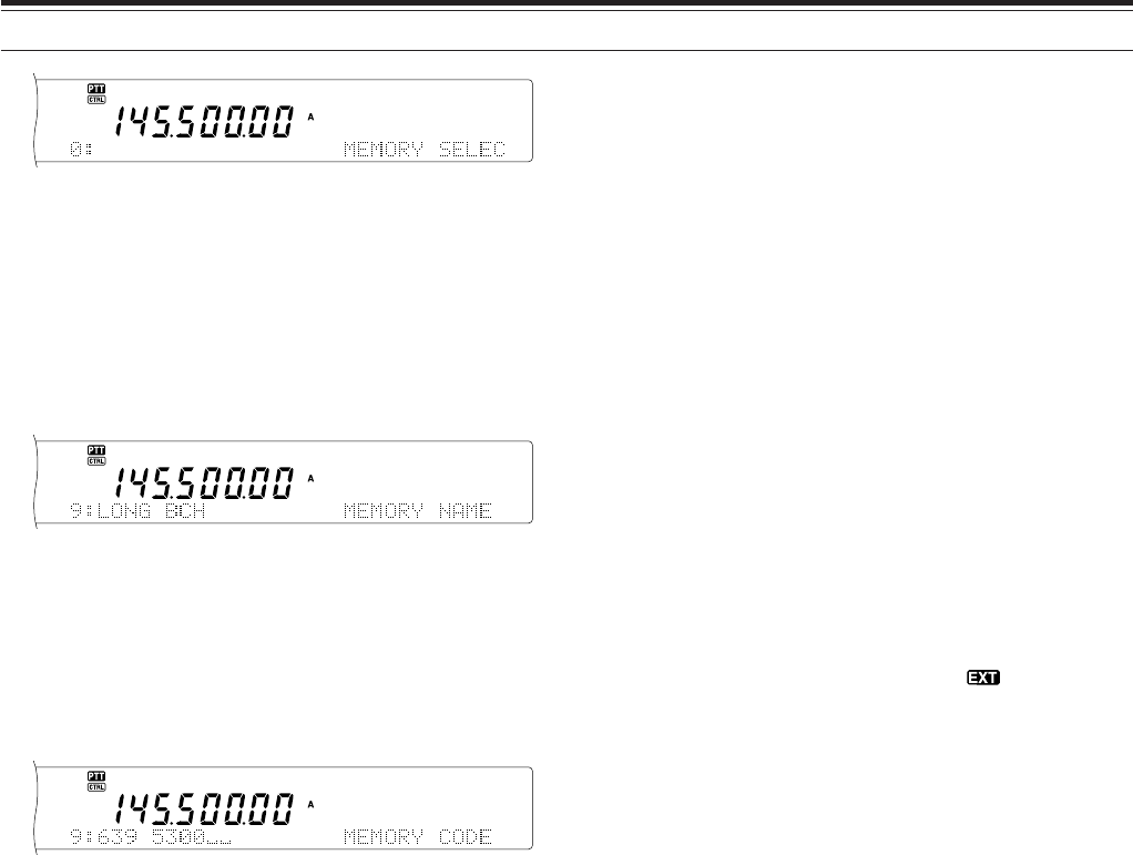
76
15 OPERATOR CONVENIENCES
4Select a DTMF Memory Channel (0 to 9) using the
MULTI/ CH control.
5Press [SUB] to enter the desired memory name.
Use [+]/ [–] to select the characters. Press
[MAIN] or [SUB] to move the cursor left or right
while entering the DTMF memory name. You can
also use the Mic DTMF keys to enter the
characters. Refer to the table on page 63 for the
available characters and numbers.
6Press [M.IN] to store the name into memory.
7Select the desired DTMF tone using [+]/ [–], then
press [SUB] to move the cursor to the right to
enter the next DTMF tone.
8Repeat step 7 until you enter all the desired DTMF
tones. You can enter a maximum of 16 DTMF
tones for each DTMF Memory Channel.
9Press [M.IN] to store the data into memory.
■Transmitting DTMF Memory Channel Data
To send the DTMF Memory Channel data while you
are transmitting:
1Press QUICK MEMO [MR] while you are
transmitting.
2The DTMF Memory Channel number and the
memory name appear on the main dot-matrix
display.
3Turn the MULTI/ CH control to select the DTMF
Memory Channel you want to transmit.
4Press QUICK MEMO [MR] to transmit the DTMF
tones.
• The DTMF tones are monitored through the
speaker while they are transmitted.
■DTMF Tone Time Length
When transmitting a series of DTMF tones, each tone
duration is set to the 50 ms (tone)/ 50 ms (mute)
format as default. Some repeaters or auto patch
controllers may require longer DTMF tones and mutes.
1Press [MENU], then turn the MULTI/ CH control to
access Menu No. 45B.
2Press [–] to select SLOW.
3Press [MENU] to exit the Menu mode.
The DTMF tones will now be sent using the 100 ms
(tone)/ 100 ms (mute) format.
DTMF Pause Period
In the DTMF Memory, you can enter blanks (pauses)
among a series of DTMF tones. The default pause
period is set to 500 ms, but you can change this
value by accessing Menu No. 45C.
1Press [MENU], then turn the MULTI/ CH control to
access Menu No. 45C.
2Press [+]/ [–] to select the desired DTMF Pause
period (default is 500 ms).
3Press [MENU] to exit the Menu mode.
HF RX ANTENNA
If you have a separate HF antenna (below 30 MHz)
only for receiving, connect the antenna coaxial cable
to the HF RX ANT connector on the rear panel. This
connector is considered to be connected to a
beverage antenna or directional loop antenna for low-
band operation.
To use the HF RX ANTENNA connector, access
Menu No. 18 and select ON. When the HF RX
ANTENNA is selected for receiving, “ ” appears on
the display.
LINEAR AMPLIFIER CONTROL
When you connect an external HF linear amplifier
to the TS-2000(X) transceiver using the REMOTE
connector, select 1 (fast switching/ 10 ms delay) or
2 (slow switching/ 25 ms delay) to activate the
internal relay so you can interface with the HF
linear amplifier {page 94}.
Some linear amplifiers require a long transmission
delay time because of the slow antenna relay
switching time. In this case, select 2 for the slow
switching.
If you have 50 MHz, 144 MHz, 430/ 440 MHz, or 1.2
GHz band linear amplifiers, connect the linear
amplifier control cable to the EXT.CONT connector
for these bands {page 96}.
1Press [MENU], then turn the MULTI/ CH control
to select Menu No. 28A (HF), 28B (50 MHz),
28C (144 MHz), 28D (430 (440) MHz), or
28E (1.2 GHz).
2Press [+]/ [–] to select OFF, 1, or 2.
• OFF disables the TS-2000(X) relay.
• 1 is 10 ms transmission delay.
• 2 is 25 ms transmission delay.
Note: If CW full break-in is enabled, 10 ms transmission delay is
applied regardless of the Menu No. 28 settings.
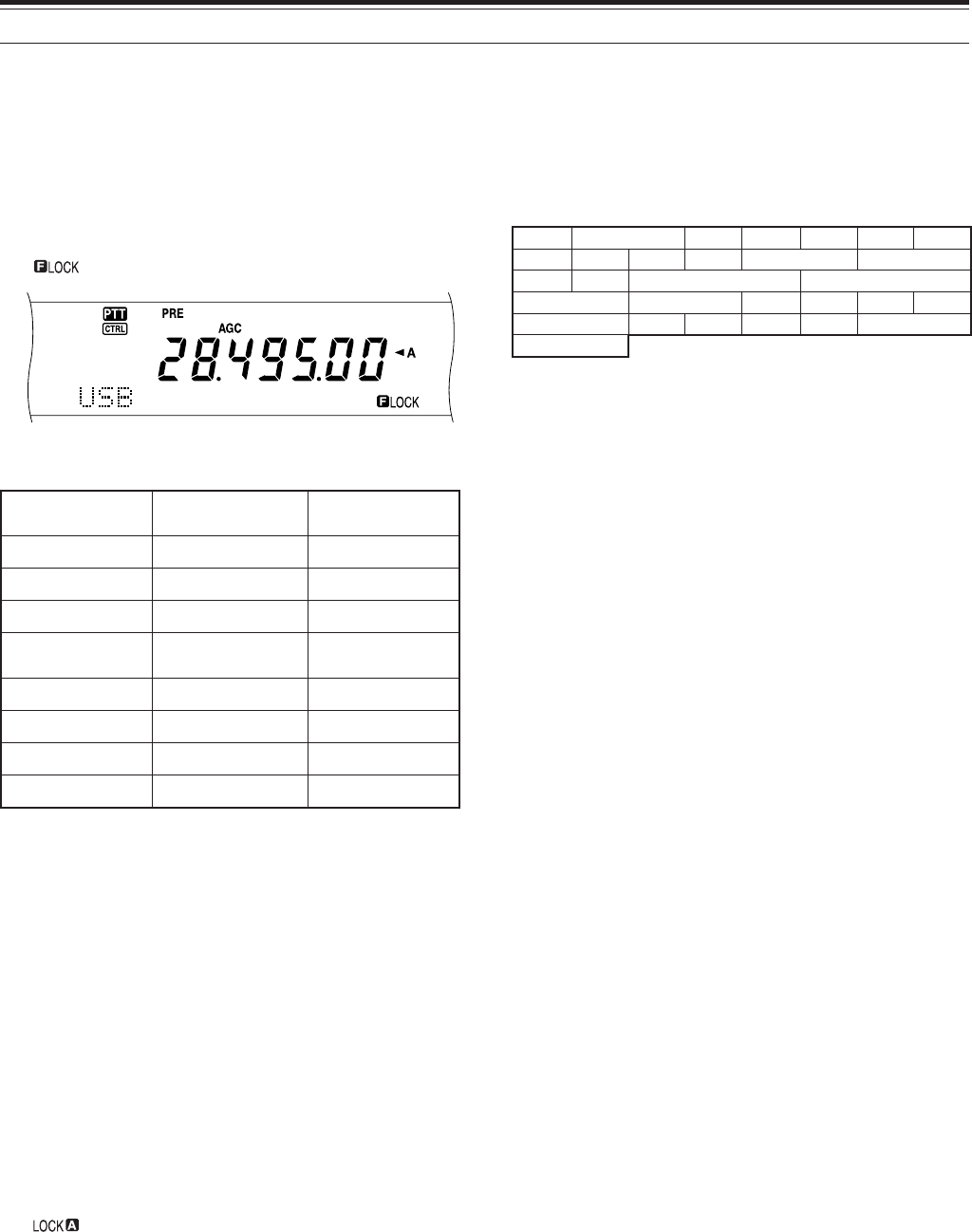
77
15 OPERATOR CONVENIENCES
• Directly select a Menu No. without pressing
[MENU] and turning the MULTI/ CH control.
• Activate the same function as one of the front
panel keys.
One of the following functions can be assigned to
each PF key. Selecting OFF assigns no function to
the PF key.
.N.A2/1TNAB=AB/A.C.BLLAC1HC
2HC3HCRLCLRTCENUTWCINOMPSD
ENIFNI.M)OMEMKCIUQ(NI.M)OMEMKCIUQ(RM
MsOFVrebmuNUNEMBN.R.NFFOzHM1
INOMXRNACSTILPSTES-FTM/OFV1ECIOV
2ECIOV
MONITOR
When you are receiving while the squelch function is
ON, weak signals become intermittent.
Or, if the CTCSS function is ON, you may want to
disable the squelch function temporarily to monitor
the current channel activities.
In these cases, use the MONITOR function to disable
the squelch function temporarily.
To assign the MONITOR function to a [PF] key on the
front panel:
1Press [MENU] and turn the MULTI/ CH control to
access Menu No. 51A.
2Press [+]/ [–] to select RX MONI.
3Press [MENU] to exit Menu mode.
Note: You can also assign the MONITOR function to a
programmable function key on an optional MC-47 microphone.
PF KEY
You can program the front panel [PF] key to assign a
function that you frequently use. The default is Voice
1 for the optional Voice Synthesizer, VS-3 {page 91}.
You can assign one of the functions in
“MICROPHONE PF KEYS” to this PF key, accessing
Menu No. 51A.
RISE TIME OF CW
The rise time of a CW signal is the time for the RF
output to rise to its maximum power after the key is
closed. The default setting, 6 ms, is fine for slow to
medium keying speed and normal weighting (dot/
dash ratio). The 4, 2 or 1 ms settings are good for
faster keying speeds.
1Press [MENU], then turn the MULTI/ CH control to
access Menu No. 32.
2Press [+]/ [–] to select the desired rise time
(default is 6 ms).
3Press [MENU] to store the setting and exit Menu
mode.
LOCK FUNCTIONS
FREQUENCY LOCK FUNCTION
Frequency Lock disables some keys and controls to
prevent you from accidentally activating a function or
changing the current settings.
Press [FUNC], [ATT/ F LOCK] to toggle Frequency
Lock ON or OFF.
•“ ” appears when this function is ON.
The following keys and controls are disabled by
Frequency Lock:
gninuTgninuT gninuT gninuTgninuT lortnoc HC/ITLUMHC/ITLUM HC/ITLUM HC/ITLUMHC/ITLUM lortnoc B/A
B=ALLACRLC
KSF/WCPSIDTNE
MA/MFOTUA/BSU/BSLNI.M
MsOFV OMEMKCIUQ ]NI.M[ OMEMKCIUQ ]RM[
LTASLES.GS/NACSTILPS
NWOD/PUM/OFVLES/zHM1
CER/1HC/1CER/2HC/2CER/3HC/3
PETS/ENIF/9–/+
Note:
◆
After activating Frequency Lock, the MULTI/ CH control and
[+]/ [–] are still available in Menu mode.
◆
After activating Frequency Lock, you can still change the transmit
frequency with the Tuning control while in TF-SET mode.
◆
After activating Frequency Lock, the MULTI/ CH control is still
available for selections other than frequency and memory
channel changes.
◆
After activating Frequency Lock, [CLR] may be available in some
situations.
LOCK ALL FUNCTION
The Lock All function disables all the keys and
controls on the TS-2000 transceiver, except [FUNC],
[PRE/ LOCK A], Mic [PTT] and [FUNC],
[ATT/ F LOCK].
Press [FUNC], [PRE/ LOCK A] to toggle between the
Lock All function ON or OFF.
•“ ” appears when this function is ON.
To return to normal operation, press [FUNC],
[PRE/ LOCK A].
MICROPHONE PF KEYS
When using the optional MC-47 or MC-52DM
microphone, you can customize the functions of the
Microphone PF1 (CALL), PF2 (VFO), PF3 (MR), and
PF4 (PF) keys. You can assign the following types of
functions to these keys via Menu Nos. 51B ~ 51E:
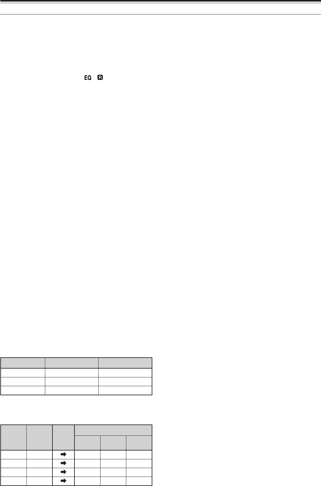
78
15 OPERATOR CONVENIENCES
If you want to reverse the output:
1Press [MENU], then turn the MULTI/ CH control to
access Menu No. 17.
2Press [+] to select ON.
3Press [MENU] to store the setting and exit Menu
mode.
The output is now reversed.
Note: If you are using headphones, the transceiver mutes. The left
channel represents the internal SP or EXT.SP1 and the right channel
represents the EXT.SP2.
S-METER SQUELCH
The S-meter Squelch function opens the squelch only
when the receiving signal has the same or greater
strength than the S-meter Squelch setting. This
function helps you to not open the squelch when
receiving weak signals that you do not want to hear.
1Press [MENU], then turn the MULTI/ CH control to
access Menu No. 19A.
2Press [+] to select ON.
3Turn the MAIN SQL control and/or the SUB SQL
control to adjust the S-meter Squelch threshold
level. When you turn SQL control, the indicators
on the S-meter move accordingly.
4Press [MENU] to store the settings and exit Menu
mode.
Note: The squelch threshold level of the S-meter squelch is
around the 9 o’clock position for FM (both MAIN and SUB SQL),
the 11 o’clock position for other modes (MAIN SQL), and the 9
o’clock position for AM (SUB SQL), regardless of the SQL controls
position.
SQUELCH HANG TIME
You can adjust the squelch hang time to continuously
monitor unstable signals. When the signal is
temporarily weaker than the S-meter Squelch
threshold level, the squelch does not mute the signal
for a short period of time. In this way, you can
continuously monitor the unstable signal.
1Press [MENU], then turn the MULTI/ CH control to
access Menu No. 19B.
2Press [+]/ [–] to select OFF, 125 ms, 250 ms, or
500 ms.
3Press [MENU] to store the settings and exit Menu
mode.
TIME-OUT TIMER
The Time-out Timer limits the time of each
transmission. It is also useful to prevent a long
accidental transmission.
1Press [MENU], then turn the MULTI/ CH control to
access Menu No. 24.
2Press [+]/ [–] to select OFF, 3 minutes, 5 minutes,
10 minutes, 20 minutes, or 30 minutes.
3Press [MENU] to store the settings and exit Menu
mode.
RX DSP EQUALIZER
EQUALIZING RECEIVING AUDIO (SSB/ FM/ AM)
Use Menu No. 20 to change the receiver frequency
responses of the target signal. You can select one
from six different receiver profiles including the
default flat response. Selecting any of the following
items from the Menu causes “ ” to appear on
the display.
• Off (OFF):
The default frequency response for SSB, FM, and
AM.
• High boost (H BOOST):
Emphasizes higher audio frequencies; effective for
a bassy voice.
• Formant pass (F PASS):
Improves clarity by suppressing audio frequencies
outside the normal voice frequency range.
• Bass boost (B BOOST):
Emphasizes lower audio frequencies; effective for
a voice with more high frequency components.
• Conventional (CONVEN):
Emphasizes by 3 dB frequencies at 600 Hz and
higher.
• User (USER):
Reserved for the ARCP software. Off is
programmed at the factory as a default.
SEPERATE SPEAKER OUTPUT
The TS-2000(X) has 2 independent receivers and is
capable of receiving 2 different frequencies at the
same time. If no external speaker is connected to the
TS-2000(X), both audio signals are mixed internally,
then output through the internal speaker.
1Connect the external speaker(s) to the EXT.SP1
and/or EXT.SP2 jack on the rear panel {page 2}.
2Press [MENU], then turn the MULTI/ CH control to
access Menu No. 16.
3Press [+]/ [–] to select 0, 1 or 2.
4Press [MENU] to store the setting.
noitceleSuneM lennahc-L lennahc-R
0dexiMbuS&niaMdexiMbuS&niaM
1niaMbuS
2buS4/1+niaMniaM4/1+buS
If you are using an external speaker on EXT.SP2, you
can configure the transceiver to make a separate
output for each receiver.
1PS.TXE 2PS.TXE TUPTUO
lanretnI )L(PS )L(1PS )R(2PS
–– √A/NA/N
√–setuM √A/N
–√√A/N √
√√ setuM √√

79
15 OPERATOR CONVENIENCES
TNC
This transceiver has a built-in TNC that is usually
used for the Packet Cluster Tune {page 53} or
SkyCommand II+ operations {page 83}. However,
you can also utilize the built-in TNC as a high
(9600 bps) or normal (1200 bps) speed TNC. The
TNC can be controlled by an external PC that is
connected to COM port on the rear panel {page 49}.
Available TNC command set is listed in the Appendix.
If you desire, you can connect an external TNC or
proprietary TNC/ MCP to ACC2 connector. To
interface an external TNC/ MCP with the TS-2000(X),
refer to the ACC2 connector information {page 95}
and accessing Menu Nos. 50B ~ 50F then configure
and adjust the Menu parameters to work with the
external TNC/ MCP.
Note: You do not have to disable the built-in TNC to interface with an
external TNC. Both the main transceiver and sub-receiver can work
independently unless the transceiver is transmitting on the same
band.
TRANSVERTER
If you have a transverter that converts the TS-2000
operating frequencies to other frequencies, you can
use this TS-2000 transceiver as a transverter exciter.
Consult the instruction manual that came with the
transverter for interfacing to the TS-2000.
1Connect the transverter to the ANT 1, ANT 2,
ANT 144, ANT 430, or ANT 1.2G (TS-2000
optional) connector on the rear of the transceiver.
2Select the exciter operating frequency on the main
transceiver of the TS-2000(X).
• The transverter will use this frequency as the
reference for converting frequencies.
3Access Menu No. 25, and select ON by pressing
[+].
• The output power is automatically set to the
lowest power for that frequency. See TX
POWER (below).
4Press [MENU] to store the setting and exit the
Menu mode.
5Press [ENT], then set the target converting
frequency, using the numeric keys.
6Press [ENT] to complete the entry.
7The transceiver displays the target transverter
frequency instead of the actual operating
frequency.
Note: When using a transverter, not all the functions of this
transceiver are available.
TX MONITOR
TX monitor allows you to monitor the on-going
transmission sound. This is convenient when you
want to check the modulation sound quality of the
transmission. In FSK mode, you can monitor the FSK
signal that the TS-2000(X) is transmitting.
1Press [FUNC], [PWR/ TX MONI].
2The current TX monitor setting appears.
3Turn the MULTI/ CH control to select the monitor
sound level from OFF, and 1 to 9.
4Press [CLR] to store the selected TX monitor
level.
Note:
◆
We recommend you use headphones when you monitor SSB,
AM, or FM mode, in order to avoid howling.
◆
The CW transmission signal cannot be monitored using the TX
monitor function. Use the CW sidetone function to monitor CW
transmissions (Menu Nos. 13 and 31).
TX POWER
You can adjust the transmission output power by
pressing [PWR/ TX MONI] and turning MULTI/ CH
control. If more precise power adjustment is
required, access Menu No. 23 and select ON. When
this menu is ON, the power adjustment steps change
as shown in the table below.
dnaB edoM 32.oNuneM FFO 32.oNuneM NO
/zHM05/FH zHM441
/WC/BSS KSF/MF W001~5 5fospetsni W001~5 1fospetsni
MA W52~5 5fospetsni W52~5 1fospetsni
044/034 zHM
/WC/BSS KSF/MF W05~5 5fospetsni W05~5 1fospetsni
MA W5.21~5 1fospetsni
zHG2.1
/WC/BSS KSF/MF W01~1 1fospetsni
MA W5.2~1 1fospetsni
Note:
◆
The output power settings are stored independently for HF, 50 MHz,
144 MHz, 430/ 440 MHz and 1.2 GHz (TS-2000/ TS-B2000
optional). As shown in the table above, you can also store different
output power settings for AM and other modes for each operating
band.
◆
For AM mode in the 430/ 440 MHz band and the 1.2 GHz (TS-
2000/ TS-B2000 optional) band, the final step is 0.5 W, rather
than 1 W.

80
15 OPERATOR CONVENIENCES
QUICK DATA TRANSFER
This transceiver has the capability to quickly and
conveniently transfer the receive frequency and mode
to another compatible transceiver. Compatible
transceivers include:
• TS-2000(X) • TS-570S/ 570D
• TS-850S • TS-870S
• TS-690S • TS-950SDX
• TS-450S
Data Transfer could be useful while contesting. A
spotting station that is searching for new contest
multipliers can quickly transfer a frequency over to
the running (main) station.
SETTING UP
■Equipment Needed
In addition to a compatible transceiver, the following
equipment is required:
Transfer to TS-2000(X), TS-570, or TS-870S:
• One cross-wired cable. This cable must have a
9-pin RS-232C female connector at both ends.
Transfer to a transceiver other than TS-2000(X),
TS-570, and TS-870S:
•KENWOOD IF-232C interface unit.
• One cross-wired cable. This cable must have a
9-pin RS-232C female connector at one end and a
25-pin RS-232C female connector at the other
end.
• One straight cable. This cable must have a
6-pin DIN male connector at both ends.
■Connections
For diagrams on how to connect the two transceivers,
see “CONNECTING PERIPHERAL EQUIPMENT”
{page 93}.
Note: If you are using a DSP-100 unit with the transceiver, turn on
the transceiver first, then turn on the DSP-100.
USING QUICK TRANSFER
When connecting with another TS-2000(X), TS-570,
or TS-870S, use the same COM connector baud rate
on each transceiver. If transferring to or from other
KENWOOD transceivers, select 4800 bps and 2 stop
bits. On the TS-2000(X), set the parameter in Menu
No. 56 to 4800 bps.
Note: While transferring data, other functions may work slower.
■Transferring Data
The TS-2000(X) transceiver works as the Master,
sending data to the Slave transceiver.
1Switch ON the Transfer function of each
transceiver.
• On the TS-2000(X), access Menu No. 52 and
select ON. For the compatible transceiver,
refer to the instruction manual that came with
the transceiver.
2On the Master, while in VFO mode, select an
operating frequency and mode.
3On the Master, press QUICK MEMO [M.IN].
• When using another TS-2000(X) as the Slave,
“PC” appears on the Slave.
• The displayed data is stored in Quick memory
channel 0 on the Master and transferred to the
Slave.
Note: If the Master has RIT switched ON, the offset frequency is
added to the receive frequency to be transferred.
■Receiving Data
The TS-2000(X) transceiver works as the Slave,
receiving data from the Master transceiver. The
Slave can receive data using either Quick memory
channel 0 or the VFO.
1Switch ON the Transfer function of each
transceiver.
• On the TS-2000(X), access Menu No. 52 and
select ON. For the compatible transceiver,
refer to the instruction manual that came with
the transceiver.
2On the Slave, access Menu No. 53 and select
either OFF (QUICK MEMO channel 0) or ON
(the VFO).
• The default is OFF (QUICK MEMO).
3On the Master, perform the appropriate operation
to send data.
• For the correct method, refer to the instruction
manual that came with the transceiver.
Note:
◆
If you always use the TS-2000(X) for receiving only, activate the
TX Inhibit function, accessing Menu No. 54 to avoid unintentional
transmission.
◆
When the Slave receives data using the VFO programmed with a
simplex frequency, the received data replaces the data on both
VFOs. On the Slave, both RIT and XIT are set to OFF.
◆
When the Slave receives data using the VFOs programmed with
split frequencies, the received data replaces the data only on the
TX side of the VFO. On the Slave, XIT is set to OFF but RIT is
not changed.
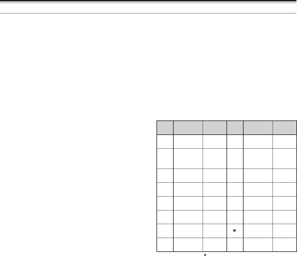
81
15 OPERATOR CONVENIENCES
COMPUTER CONTROL
By connecting this transceiver to a computer, you can
change the computer into an electronic console from
which you can remotely control functions of the
transceiver. This capability makes remote operation
of your transceiver possible from across the room,
from another room, or when coupled with other
commercially available products and where lawful,
from another city, state, or country via a telephone
connection.
Note:
◆
You can use the front panel controls while using computer
control. Settings done from the front panel are effective
immediately.
◆
After the computer is disconnected or turned off, all values and
settings on the front panel are restored.
SETTING UP
■Equipment Needed
• A PC equipped with an RS-232C serial port.
• One straight cable. This cable must have a 9-pin
D-Sub RS-232C female connector at one end, and
at the other end a 9-pin or a 25-pin D-Sub
RS-232C female connector that mates with the
RS-232C port of your computer.
• Transceiver control application.
To design your programs, consult “APPENDIX” for the
necessary information.
■Connections
Connecting the transceiver to the computer is easy.
See the diagram given in “CONNECTING
PERIPHERAL EQUIPMENT” {page 93}.
Note: Before connecting this transceiver to the computer, switch
OFF the power to both the transceiver and the computer.
COMMUNICATION PARAMETERS
In order to control the transceiver by computer, you
must first choose the communication parameters.
1On the computer, configure your transceiver
control application for 8 data bits, 1 stop bit and
no parity.
2On the transceiver, select the same transfer rate
and number of stop bits via Menu No. 56.
• The defaults are 9600 bps and 1 stop bit.
Note: To reliably use the 38400 or 57600 bps transfer rates, the
RS-232C port of the computer must support these high-speed
communications parameters.
REMOTE MICROPHONE CONTROLLER
If you have a DTMF microphone, you can use the
microphone as a wired remote control unit as
described below.
1Plug the DTMF microphone into the microphone
connector of the transceiver.
2Press [MENU], then turn the MULTI/ CH control to
access Menu No. 45D.
3Press [+] to select ON.
4Press [MENU] to store the setting and exit Menu
mode.
The DTMF keys function as follows:
FMTD yek noitcnuF CNUF edom FMTD yek noitcnuF CNUF edom
1nacS–9
hcleuqS
1
nwoD/pU –
2/enoT /SSCTC SCD
edoC tceleS 0RWP
1
nwoD/pU –
3VERTFIHSATNE–
4zHM–BLRTC /NIAM BUS
5INOM KCOL NO
2
CretaepeR–
61ecioV KCOL FFO
2
DCNUF CNUF FFO
7emuloV
1
–nwoDnwoD
8dnaB
1
–# pUpU
1Use the [#] (Up) and [ ](Down) keys to change the settings of
these functions.
2The LOCK function is for the microphone keypad.
Note:
◆
Microphone Remote does not function while transmitting.
◆
You can use the DTMF Memory function {page 75} with the
Microphone Remote function.
◆
The Repeater function is available for K-type models only.
◆
Normally, pressing [2] cycles through Tone, CTCSS, DCS, and
OFF. However, if 1750 Hz is selected for Tone, pressing [2] will
only transmit the 1750 Hz tone. To return to Tone/ CTCSS/ DCS
mode, you must first deselect 1750 Hz for Tone.
◆
Press [D] to enter FUNC mode, to use the 2nd function of the
DTMF keys. Pressing [D] while in FUNC mode will exit FUNC
mode.
◆
[FUNC] on the transceiver works independently from the
Microphone Remote [FUNC] key.
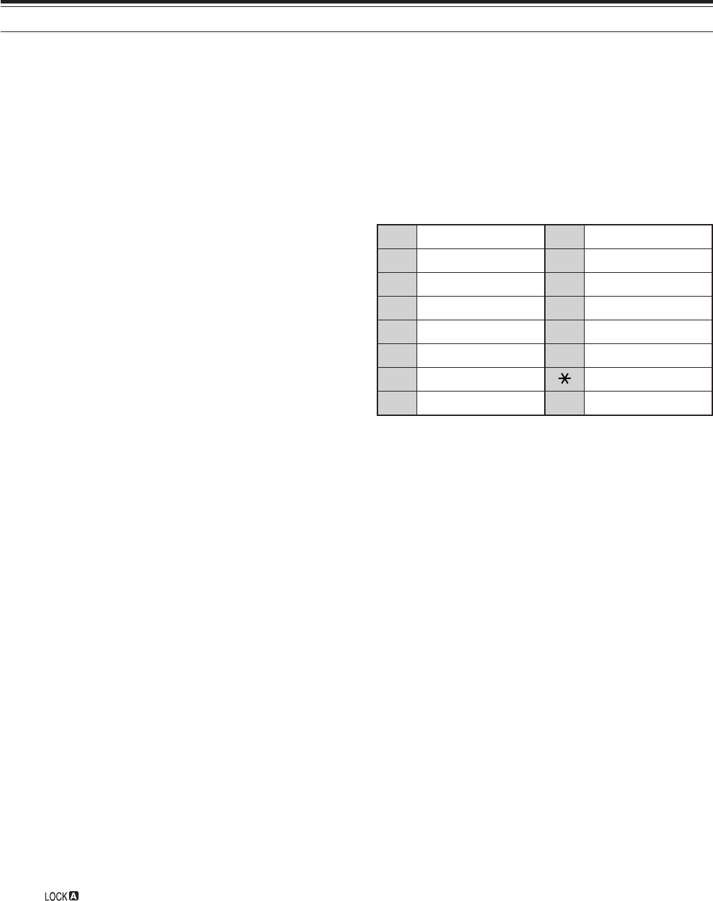
82
15 OPERATOR CONVENIENCES
WIRELESS REMOTE CONTROL
(K-type ONLY)
If you have a Kenwood TH-D7A handheld transceiver,
you can use it to remotely control the 144 MHz and
440 MHz bands of the TS-2000(X) transceiver, using
FM mode. You will be controlling one band on the
TS-2000(X) transceiver while sending DTMF tones to
the other band from the remote control transceiver.
This function is useful, for example, when you want to
control the VHF/ UHF FM repeater function of the
TS-2000(X) transceiver from a location outside your
home or vehicle.
Note:
◆
To remotely control the TS-2000(X), you can also use a handheld
transceiver which does not have a remote control function, but a
DTMF function. You must, however, manually send DTMF tones
for control code strings. Skip steps 1 and 3 in “PREPARATION”,
below.
◆
FCC rules permit you to send control codes only on the 440 MHz
band.
PREPARATION
Assuming that the 144 MHz band of the TS-2000
transceiver will be controlled.
On the control transceiver:
1Program a 3-digit secret number.
• If you are using a TH-D7A, see “WIRELESS
REMOTE CONTROL” in its instruction manual.
2Select the transmit frequency on the 440 MHz
band.
3Enter the Remote Control mode.
On the TS-2000 transceiver:
4Access Menu 61C, and select the same secret
number that you selected in step 1.
5Select the receive frequency on the 440 MHz
band of the sub-receiver.
• Mate this frequency with the transmit frequency
on the control transceiver.
6Select the 144 MHz band as the TX band or
Control band for the main transceiver.
7To have the TS-2000(X) transceiver send a control
acknowledgment to the handheld, access Menu
61D and select “ON”.
• DTMF tones which represent the secret
number will be used as an acknowledgment.
8Access Menu 61E and select “ON”.
•“ ” appears when the TS-2000(X) enters
Remote Control mode.
CONTROL OPERATION
When in Remote Control mode, the DTMF keys of the
control transceiver will function as shown in the table
below. Each time you press the desired key, the
transceiver will automatically enter transmit mode and
send the corresponding command to the mobile.
Note: If you are using a transceiver without a remote control
function, manually send “AXXX#YA#” where “XXX” is your 3-digit
secret number and “Y” is a single-digit control command. If you do
not add ”A#” on the end, you can skip sending “AXXX#” next time;
however, the mobile may be accidentally controlled by other stations.
1NOSCD 9RM
2NOENOT 0WOL
3NOSSCTC ARETNE
4FFOSCD BLESENOT
5FFOENOT CNORETAEPER
6FFOSSCTC DFFORETAEPER
7LLAC NWOD
8OFV #PU
To change the transmit/ receive frequency:
([VFO] ➡ [ENTER] ➡ [0] ~ [9] (enter the necessary
digits) ➡ [ENTER]) or ([VFO] ➡ [UP]/ [DOWN])
To recall a memory channel:
([MR] ➡ [ENTER] ➡ [0] ~ [9] (enter the necessary
digits) ➡ [ENTER]) or ([MR] ➡ [UP]/ [DOWN])
To change the tone (or CTCSS) frequency:
([TONE SEL] ➡ [0] ~ [9] (enter 2 digits; ex. [0], [5])
➡ [TONE SEL])
• Use Nos. 01 to 38 shown in the table on page 35.
• First activate the Tone or CTCSS function. You
can select a separate tone frequency for the Tone
and CTCSS functions.
Note: While in Wireless Remote Control mode, you can perform only
the following operations on the TS-2000(X) transceiver.
•
Transmit
•
Acknowledge ON/ OFF
•
Secret Number Change
•
Partial/ Full Reset
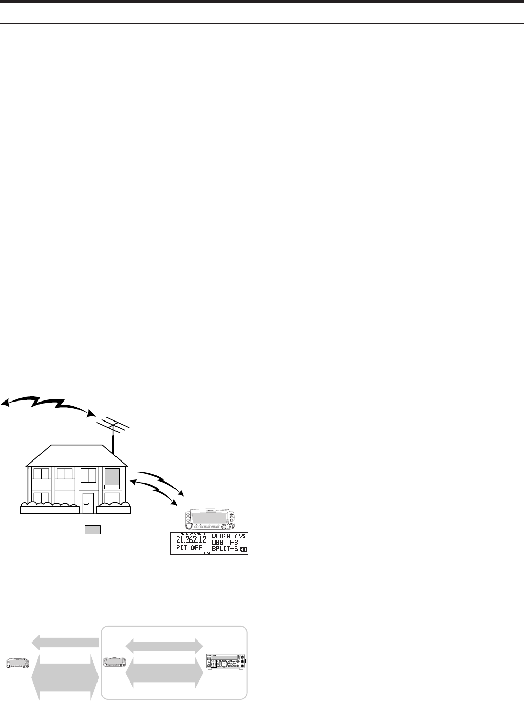
83
15 OPERATOR CONVENIENCES
SKY COMMAND II + (K-type ONLY)
The Sky Command II+ allows you to remotely control
the TS-2000(X) transceiver from a separate location.
Since the TS-2000(X) transceiver has an independent
VHF and UHF sub-receiver in addition to the main
transceiver, the sub-receiver can work as a
“Transporter” without requiring another VHF/ UHF
transceiver.
So, if you already have Kenwood’s TH-D7A handheld
or TM-D700A mobile transceiver, you can immediately
start enjoying Sky Command II+ features to remotely
control the HF/ 50 MHz band of your TS-2000(X).
Or, if you have a friend who has another TS-2000(X),
you can also use his/her TS-2000(X) as a
“Commander” (a remote unit) to control the HF/
50 MHz band of your TS-2000(X) at home, using VHF
and UHF bands.
You will use one transceiver as a remote control unit,
called a “Commander”. The VHF/ UHF sub-receiver
in the TS-2000(X) transceiver is called the
“Transporter”. It will function as an interface between
the Commander and the HF/ 50 MHz band of the
TS-2000(X) main transceiver.
This system allows you, for example, to watch for and
hunt DX while washing your car, or to operate the HF
transceiver while relaxing in your car, living room, or
patio, instead of actually operating inside your shack.
SKY COMMAND II + DIAGRAM
PF
ATT PRE-AMP
VOX PROC
SEND
CH1 MIC
CW
FSK
LSB
USB
FM
AM
AT TUNE
POWER HF TRANSCEIVER TS-570D
PHONES 1
CH2
2
CH3
3
ANT
4
REC
5
FINE
6
NB
7
AGC/TONE
8
REV
9
CLR
F.LOCK
0ENT
MIC
PWR
KEY
DELAY MENU 1MHz
SPLIT
M/V
DOWN UP
MR
TF-SET
A=B
SCAN M>VFO M.IN
M.IN
FILTER
CW TUNE
B.C.
N.R.
A/B
CLEAR
RIT
XIT
RIT/XIT
IF SHIFT SQL
CH
46
010
28
AF RF
L
O
W
C
U
T
HIGH
DSP SLOPE
LOW
46
010
28
+–
VHF freq.
Commander Transporter
Audio Audio
UHF freq.
Audios
Control commands
tResponse
Control commands
tResponse
PREPARATION
Although you can use either a TM-D700A, a TH-D7A,
or another TS-2000(X) transceiver as a “Commander”
(an external remote control unit), the following
procedure shows how to set up your TS-2000 as a
“Transporter” at a base station and the TM-D700A as
a “Commander”.
TS-2000 (Transporter) Setup:
1Press [MENU], then turn the MULTI/ CH control to
access Menu No. 62A.
2Press [SUB] then enter your callsign (ex: WD6DJY)
as a “Commander” callsign, using [+]/ [–] or the
MULTI/ CH control. To move the cursor, press
[MAIN] or [SUB]. Press [M.IN] to store the
callsign to Menu No. 62A.
3Press [MENU], then turn the MULTI/ CH control to
access Menu No. 62B.
4Press [SUB] then enter your alias callsign
(ex: WD6DJY-1) as a “Transporter” callsign, using
[+]/ [–] or the MULTI/ CH control. To move the
cursor, press [MAIN] or [SUB]. Press [M.IN] to
store the callsign to Menu No. 62B.
Note: You can use alpha-numeric characters, A to Z, 0 to 9 and
“-”. The callsign must be no more than 9 characters long,
including “-”. Also, the following callsign formats cannot be
entered:
•
WD6DJYZ
If you use only letters and numbers for the callsign, the
maximum length is 6 characters.
•
WD6-DJY-1
You cannot use more than 1 “-” within a callsign.
•
-WD6DJY
You cannot use a “-” as the first callsign character.
•
WD6DJY-19
An SSID must be within the range of 1 to 15.
5Access Menu No. 62C, then turn the MULTI/ CH
control to select a CTCSS tone frequency for Sky
Command II+ (default is 88.5 Hz).
6Access Menu No. 62D and select the
communication speed for Sky Command II+.
Select 1200 bps for TM-D700A (9600 bps can be
used only when you use another TS-2000(X) as a
“Commander”).
7Access Menu No. 46 and select SUB.
8Select a 144 MHz band frequency in FM mode on
the main transceiver and 440 MHz band frequency
in FM mode for the sub-receiver for Sky Command
II+ operation.
TM-D700A (Commander) Setup:
1Access Menu 4–1 and 4–2 to enter the same
callsign that you entered for TS-2000(X).
2Access Menu 4–3 to select the same CTCSS tone
frequency that you selected for TS-2000(X)
(Transporter).
Note: Refer to Chapter 17, Sky Command II, of the TM-D700A
instruction manual for details on how to enter the callsign and CTCSS
tone frequency.
Your shack
HF/ 50 MHz
VHF
UHF
TM-D700A/ TH-D7A/
TS-2000(X)
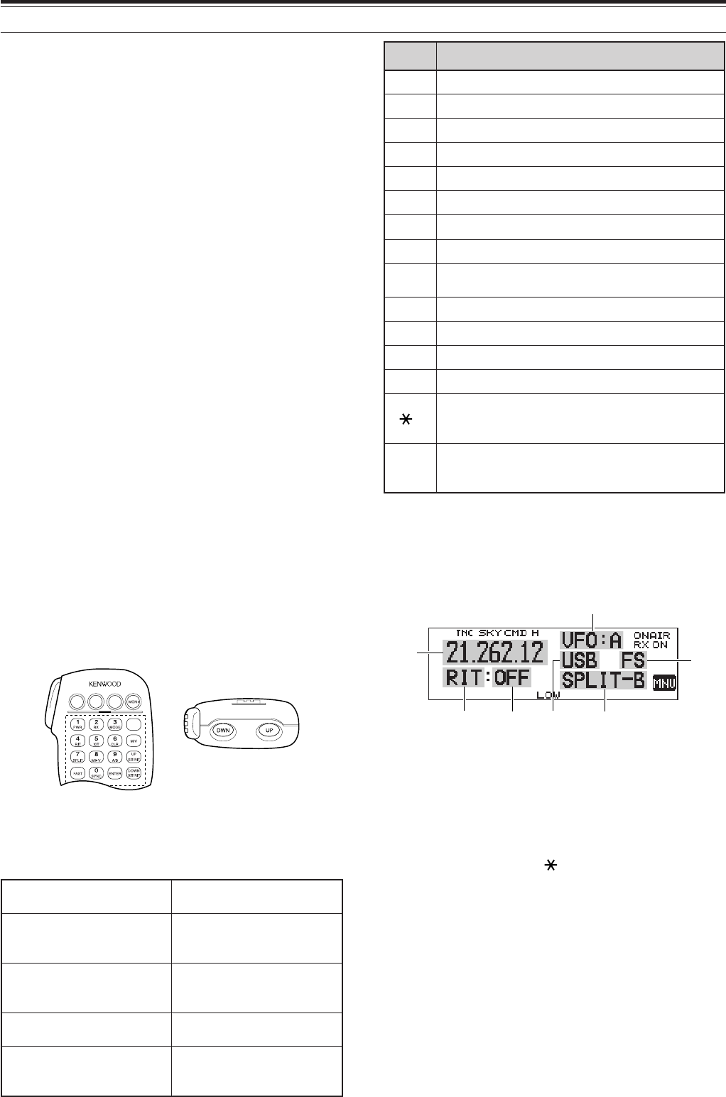
84
15 OPERATOR CONVENIENCES
Starting Sky Command II+ operation:
After you have completed the following setups, you
can start Sky Command II+ operation. Without
programming these parameters, you cannot perform
Sky Command II+ operation.
On the TS-2000 (Transporter):
1Select the desired HF frequency that you want to
be controlled on the main transceiver.
2Select an open VHF frequency in FM mode for the
main transceiver and another open UHF
frequency in FM mode for the sub-receiver.
3Press [MENU], then turn the MULTI/ CH control to
access Menu No. 62E.
4Select T-PORTER (Transporter).
5Press [MENU] to enter the Transporter mode.
On the TM-D700A (Commander):
1Select the same VHF and UHF frequencies that
you selected for the TS-2000 (Transporter).
2Access Menu 4–4 to select COMMANDER.
•“PRESS [0] KEY TO START COMMANDER!!”
appears.
3Press [0] on the DTMF Mic of the TM-D700A to
start the Sky Command II+ operation.
CONTROL OPERATION
After setting up both the TS-2000 (Transporter) and
the TM-D700A (Commander) for Sky Command II+
operation, press Mic [0] on the Commander. While in
Sky Command mode, the Mic keys of the
Commander will function as described below.
Each time you press a key, the Commander will
automatically enter transmit mode and send the
corresponding control command to the Transporter.
FHehthctiwsoT FFOreviecsnart ciMsserP ]1[ .
ycneuqerfehtegnahcoT nolennahcyromemro reviecsnartFHeht
ciMsserP ]PU[ /]NWD[ .
nanooiduatimsnartoT ycneuqerfFH ciMdlohdnasserP ]TTP[ ehtotnikaepsneht, .enohporcim
nanooiduaevieceroT ycneuqerfFH ciMsserP ]2[ .
dnabFHUehtrotinomoT rednammoCehtno ciMehtsserP FP yek rotinoMehtotdengissa .noitcnuf
yeKciM noitcnuF
1FFOrewoP
2FFO/NOeviecerycneuqerfFH
3hctiwsedomnoitaludoM
4FFO/NOTIR
5FFO/NOTIX
6raelctesffoTIXrotesffoTIR
7FFO/NOycneuqerf-tilpS
8OFVotyromeMmorfrefsnarT
9hctiwsBOFV/AOFV:edomOFVnI egnahcon:edomllaceRyromeMnI
0FHmorf(eveirtersgnittestnerruCreviecsnart)
BhctiwsedomllaceRyromeM/OFV
CesaercniycneuqerftesffoTIR/TIX
DesaercedycneuqerftesffoTIR/TIX
1
:edomWCro,BSU,BSLnI hctiwszHk1/zH01 hctiwszHk01/zHk1:edomMAroMFnI
#
2
NOyrtneycneuqerf:edomOFVnI rebmunlennahc:edomllaceRyromeMnI NOyrtne
1“FS” appears when you select 1 kHz step (LSB/ USB/ CW) or 10 kHz
step (FM/ AM).
2After pressing Mic [#], press Mic [0] to [9] to enter a frequency or
memory channel number.
When Mic [0] is pressed, the Commander shows the
current settings of the HF transceiver:
q
eyr
u
w
t
qHF frequency
wVFO: A, VFO: B,
MR: 00 ~ 99 (memory channel number)
eRIT, XIT
rOFF, –9.99 ~ +9.99
tLSB, USB, CW, FM, or AM
ySPLIT–A: VFO A is used for transmitting.
SPLIT–B: VFO B is used for transmitting.
SPLIT–M: A memory channel is used for transmitting.
u“FS” appears when Mic [] is pressed.
Note:
◆
After pressing [MENU], you can access only Menu 4–4.
◆
The Transporter will transmit its call sign in Morse code every
10 minutes, using the 144 MHz band.
◆
The APO timer will not operate on the transceiver while the
Transporter is ON.
◆
You must set VHF frequency on the main transceiver and UHF
frequency on the sub-receiver. Otherwise, the Sky Command II+
may not operate properly.
◆
When the TS-2000(X) exits the Sky Command II+ operation, the
operating frequency of VFO A will be set to the VHF frequency
that the Sky Command II+ was operated.
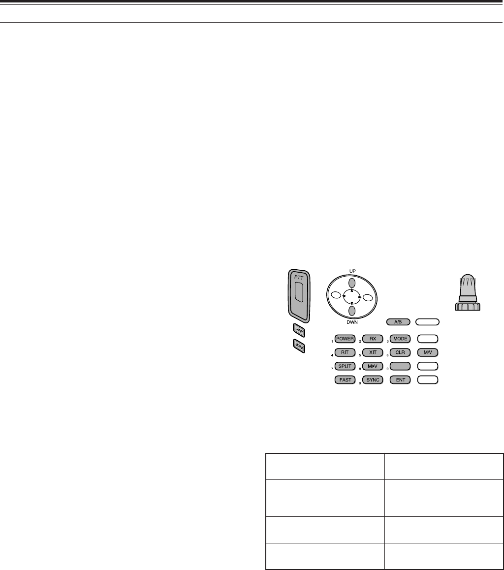
85
15 OPERATOR CONVENIENCES
USING TH-D7A AS A COMMANDER
To use a TH-D7A transceiver as a “Commander” (an
external remote control unit), follow the steps below.
Basically, it is the same as using a TM-D700A as a
“Commander” (described on the previous page).
TS-2000(X) (Transporter) Setup:
1Press [MENU], then turn the MULTI/ CH control to
access Menu No. 62A.
2Enter your callsign (ex: WD6DJY) as a
“Commander” callsign, using [+]/ [–] or the
MULTI/ CH control. To move the cursor, press
[MAIN] or [SUB]. Press [M.IN] to store the
callsign to Menu No. 62A.
3Press [MENU], then turn the MULTI/ CH control to
access Menu No. 62B.
4Enter your alias callsign (ex: WD6DJY-1) as a
“Transporter” callsign, using [+]/ [–] or the
MULTI/ CH control. To move the cursor, press
[MAIN] or [SUB]. Press [M.IN] to store the
callsign to Menu No. 62B.
Note: You can use alpha-numeric characters, A to Z, 0 to 9 and
“-”. The callsign must be no more than 9 characters long
including “-”. Also, the following callsign formats cannot be
entered:
•
WD6DJYZ
If you use only letters and numbers for the callsign, the
maximum length is 6 characters.
•
WD6-DJY-1
You cannot use more than 1 “-” within a callsign.
•
-WD6DJY
You cannot use a “-” as the first callsign character.
•
WD6DJY-19
An SSID must be within the range of 1 to 15.
5Access Menu No. 62C, then turn the MULTI/ CH
control to select a CTCSS tone frequency for Sky
Commander II+ (default is 88.5 Hz).
6Access Menu No. 62D and select the
communication speed for Sky Command II+.
Select 1200 bps for TH-D7A (9600 bps can be
used only when you use another TS-2000 as a
“Commander”).
7Assign the TNC band to the sub-band by
accessing Menu No. 46 and select SUB.
8Select a 144 MHz band frequency in FM mode on
the main transceiver and 440 MHz band frequency
in FM mode for the sub-receiver for Sky Command
operation.
TH-D7A (Commander) Setup:
1Access Menu 4–1 to enter the same callsign that
you entered for the Commander (ex: WD6DJY).
2Access Menu 4–2 to enter the same callsign that
you entered for the Transporter (ex: WD6DJY-1).
3Access Menu 4–3 to select the same CTCSS tone
frequency that you selected for the TS-2000(X)
(Transporter).
4Set the same frequencies that you selected for the
“Transporter” for the VHF and UHF bands.
Note: Refer to Chapter 19, Sky Command II, of the TH-D7A
instruction manual for details on how to enter the callsign and CTCSS
tone frequency.
CONTROL OPERATION
First, switch the TS-2000 transceiver ON and select
T-PORTER (Transporter) from Menu 62E.
Then, access Menu 4–4 on the TH-D7A and select
“COMMANDER”. “PUSH [0] KEY TO START
COMMANDER!!” appears.
Press [0] on the TH-D7A to start Sky Command
mode.
When in Sky Command mode, the keys of the TH-D7A
(Commander) will function as described below. Only
[LAMP], [MONI], and the VOL control functions will
not change.
Each time you press the desired key, the Commander
will automatically enter transmit mode and send the
corresponding control command to the TS-2000
(Transporter).
FHehthctiwsoT FFOreviecsnart sserP ]REWOP[]REWOP[ ]REWOP[ ]REWOP[]REWOP[ .
anooiduatimsnartoT ycneuqerfFH
ehtdlohdnasserP TTPTTP TTP TTPTTP otnikaepsneht,hctiws .enohporcimeht
nanooiduaevieceroT ycneuqerfFH sserP ]XR[]XR[ ]XR[ ]XR[]XR[ .
dnabFHUehtrotinomoT rednammoCehtno dlohdnasserP ]INOM[]INOM[ ]INOM[ ]INOM[]INOM[ .
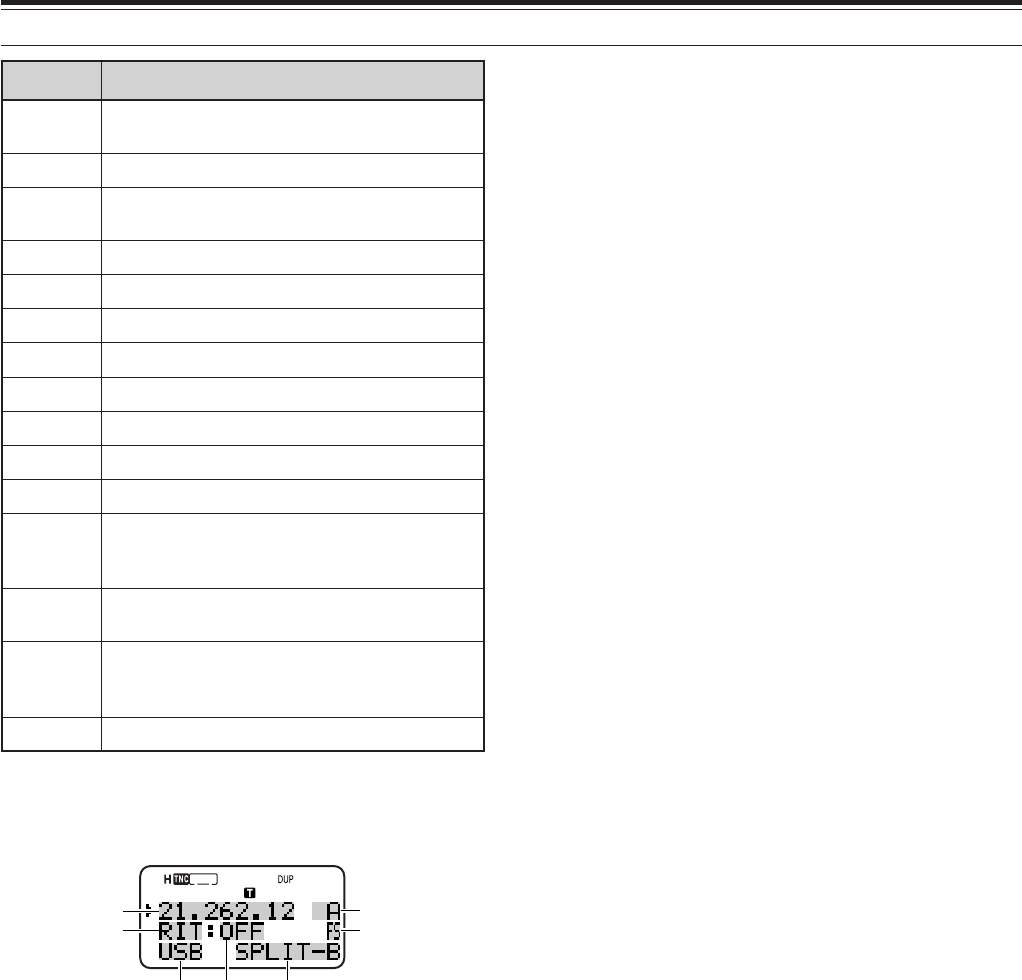
86
15 OPERATOR CONVENIENCES
yeK noitcnuF
gninuTgninuT gninuT gninuTgninuT lortnoc rebmunlennahcyromemroycneuqerF egnahc
PUPUPUPUPU/NWDNWD NWD NWDNWD egnahctesffoTIXrotesffoTIR
B/AB/A B/A B/AB/A hctiwsBOFV/AOFV:edomOFVnI egnahcon:edomllaceRyromeMnI
REWOPREWOP REWOP REWOPREWOP
1
FFO/NOrewoP
XRXRXRXRXR
1
FFO/NOeviecerycneuqerfFH
EDOMEDOM EDOM EDOMEDOM
1
hctiwsedomnoitaludoM
TIRTIR TIR TIRTIR
1
FFO/NOTIR
TIXTIX TIX TIXTIX
1
FFO/NOTIX
RLCRLC RLC RLCRLC
1
raelctesffoTIXrotesffoTIR
TILPSTILPS TILPS TILPSTILPS
1
FFO/NOycneuqerf-tilpS
MM
M
MM ➧VV
V
VV
1
OFVotyromeMmorfrefsnarT
TSAF :edomWCro,BSU,BSLnI hctiwszHk1/zH01 hctiwszHk01/zHk1:edomMAroMFnI
CNYSCNYS CNYS CNYSCNYS
1
eveirtersgnittestnerruC )reviecsnartFHmorf(
TNETNE TNE TNETNE NOyrtneycneuqerf:edomOFVnI rebmunlennahc:edomllaceRyromeMnI NOyrtne
V/MV/M V/M V/MV/M hctiwsedomllaceRyromeM/OFV
1After pressing [ENT], you can use these keys as numeric keys to
enter a frequency or memory channel number.
When [0/ SYNC] is pressed, the Commander shows
the current settings of the HF transceiver:
q
e
yr u
w
t
qHF frequency
wA (VFO A), B (VFO B),
00 ~ 99 (memory channel number)
eRIT, XIT
rOFF, –9.99 ~ +9.99
t“FS” appears when [FAST] is ON.
yLSB, USB, CW, FM, or AM
uSPLIT–A: VFO A is used for transmitting.
SPLIT–B: VFO B is used for transmitting.
SPLIT–M: A memory channel is used for transmitting.
Note:
◆
On the Transporter, only [LAMP], [MONI], and [MENU] will
function. Pressing any other key will simply cause the
Transporter to generate an error beep.
◆
After pressing [MENU], you can access only Menu 4–4.
◆
The Transporter will transmit its call sign in Morse code every
10 minutes, using the 144 MHz band.
◆
The APO timer will not operate on the transceiver while the
Transporter is ON.

87
15 OPERATOR CONVENIENCES
USING ANOTHER TS-2000 AS A COMMANDER
To use another TS-2000(X) transceiver as a
“Commander” (an external remote control unit), follow
the steps below. Basically, it is the same as using a
TM-D700A as a “Commander” (described on
pages 83 and 84).
TS-2000(X) (Transporter) Setup:
1Press [MENU], then turn the MULTI/ CH control to
access Menu No. 62A.
2Enter your callsign (ex: WD6DJY) as a
“Commander” callsign, using [+]/ [–] or the
MULTI/ CH control. To move the cursor, press
[MAIN] or [SUB]. Press [M.IN] to store the
callsign to Menu No. 62A.
3Press [MENU], then turn the MULTI/ CH control to
access Menu No. 62B.
4Enter your alias callsign (ex: WD6DJY-1) as a
“Transporter” callsign, using [+]/ [–] or the
MULTI/ CH control. To move the cursor, press
[MAIN] or [SUB]. Press [M.IN] to store the
callsign to Menu No. 62B.
Note: You can use alpha-numeric characters, A to Z, 0 to 9 and
“-”. The callsign must be no more than 9 characters long
including “-”. Also, the following callsign formats cannot be
entered:
•
WD6DJYZ
If you use only letters and numbers for the callsign, the
maximum length is 6 characters.
•
WD6-DJY-1
You cannot use more than 1 “-” within a callsign.
•
-WD6DJY
You cannot use a “-” as the first callsign character.
•
WD6DJY-19
An SSID must be within the range of 1 to 15.
5Access Menu No. 62C, then turn the MULTI/ CH
control to select a CTCSS tone frequency for Sky
Command II+ (default is 88.5 Hz).
6Access Menu No. 62D and select the
communication speed for Sky Command II+.
• Select 1200 bps or 9600 bps.
7Access Menu No. 46 and select SUB.
8Select a 144 MHz band frequency in FM mode on
the main transceiver and 440 MHz band frequency
in FM mode for the sub-receiver for Sky Command
II+ operation.
TS-2000 (Commander) Setup:
1Access Menu No. 62A and 62B to enter the same
callsign that you entered for the TS-2000
(Transporter).
2Access Menu No. 62C to select the same CTCSS
tone frequency that you selected for the TS-2000
(Transporter).
3Access Menu No. 62D and select the same
communication speed that you selected for the
TS-2000 (Transporter).
4Access Menu No. 46 and select SUB.
5Set the same frequencies that you selected for the
“Transporter” for the main transceiver and sub-
receiver.
Starting Sky Command ll+ operation:
1On the Transporter, access Menu No. 62E.
2Select T-PORTER (Transporter).
3On the Commander, access Menu No. 62E.
4Select COMMANDER (Commander).
5Press [MAIN] on the Commander to start the
operation.
lortnoC noitcnuF
NIAMNIAM NIAM NIAMNIAM lortnoc gnitarepoehtlortnocotnruT .ycneuqerf
HC/ITLUMHC/ITLUM HC/ITLUM HC/ITLUMHC/ITLUM lortnoc gnitarepoehtlortnocotnruT .yldiparycneuqerf
]NIAM[]NIAM[ ]NIAM[ ]NIAM[]NIAM[ tnerrucehtrotinomotsserP .ycneuqerfgniviecer
]BUS[]BUS[ ]BUS[ ]BUS[]BUS[ ehtllaezinorcnys-erotsserP retropsnartehtneewtebnoitamrofni .rednammocdna
]+[]+[ ]+[ ]+[]+[ /]–[]–[ ]–[ ]–[]–[ ehtnwodropuevomotsserP zHM05/FH(dnabgnitarepo .)sdnaboidarruetama
]M/OFV[]M/OFV[ ]M/OFV[ ]M/OFV[]M/OFV[ edomOFVneewtebelggototsserP .edomllaceRyromeMdna
]TNE[]TNE[ ]TNE[ ]TNE[]TNE[
ycneuqerfderisedaretneotsserP arodapyekciremunehtgnisu yromeMnirebmunlennahcyromem .edomllaceR
M[M[M[M[M[ss
s
ss ]OFV]OFV ]OFV ]OFV]OFV yromemehtrefsnartotsserP .OFVotnoitamrofnilennahc
]B/A[]B/A[ ]B/A[ ]B/A[]B/A[ .BroAOFVtcelesotsserP
]TILPS[]TILPS[ ]TILPS[ ]TILPS[]TILPS[ NOnoitarepoTILPSelggototsserP .FFOdna
]BSU/BSL[]BSU/BSL[ ]BSU/BSL[ ]BSU/BSL[]BSU/BSL[ .BSUroBSLtcelesotsserP
]KSF/WC[]KSF/WC[ ]KSF/WC[ ]KSF/WC[]KSF/WC[ ebtonnacKSF.WCtcelesotsserP .detceles
]MA/MF[]MA/MF[ ]MA/MF[ ]MA/MF[]MA/MF[ .MAroMFtcelesotsserP
]TIR[]TIR[ ]TIR[ ]TIR[]TIR[ /]TIX[]TIX[ ]TIX[ ]TIX[]TIX[ TIXro/dnaTIRehtetavitcaotsserP .noitcnuf
]RAELC[]RAELC[ ]RAELC[ ]RAELC[]RAELC[ ycneuqerftesffoehtraelcotsserP .TIXro/dnaTIRrof
]CORP[]CORP[ ]CORP[ ]CORP[]CORP[ hceepSehthctiwsotsserP .NOnoitcnuFrossecorP
].N.A[].N.A[ ].N.A[ ].N.A[].N.A[ hctoNotuAehtelggototsserP .FFOdnaNOnoitcnuf
].C.B[].C.B[ ].C.B[ ].C.B[].C.B[ lecnaCtaeBehtelggototsserP .FFOdnaNOnoitcnuf
].R.N[].R.N[ ].R.N[ ].R.N[].R.N[ ,1noitcudeResioNtcelesotsserP .FFOro,2noitcudeResioN
]CNUF[]CNUF[ ]CNUF[ ]CNUF[]CNUF[ ,]TA[]TA[ ]TA[ ]TA[]TA[ dna1TNAneewtebelggototsserP .dnabzHM05/FHrof2TNA
]CNUF[]CNUF[ ]CNUF[ ]CNUF[]CNUF[ ,]LEVEL/BN/7[]LEVEL/BN/7[ ]LEVEL/BN/7[ ]LEVEL/BN/7[]LEVEL/BN/7[ reknalBesioNehtelggototsserP .FFOroNOnoitcnuf
]CNUF[]CNUF[ ]CNUF[ ]CNUF[]CNUF[ ,[[
[
[[]]
]
]] .FFOrewopretropsnarTehthctiwS

88
15 OPERATOR CONVENIENCES
These keys and controls are available on the
Commander to control the Transporter.
Note:
◆
When the synconize operation is incomplete, the main display
of the Commander may disappear. In this case, press [SUB] to
re-syncronze.
◆
You cannot recall memory channels 100 to 299 using [ENT]
and the numeric keys.
To recall memory channels 100 ~ 299,
use [+]/ [–].
◆
You can recall only the memory channels that have HF/ 50 MHz
frequencies.
◆
Do not use VHF/ UHF frequencies that are suffering from the
harmonics of HF/ 50 MHz transmissions.
◆
The frequency control operations, such as the Tuning control
and RIT/ XIT control, are much slower than using direct controls,
because each control command (in steps of 10 Hz) is sent as
packet data.
◆
When you change the frequency continuously, using the Tuning
control or the MULTI/ CH control, the last entry of the
Commander frequency is reflected on the HF/ 50 MHz
transceiver.
◆
Since Sky Command II+ requires 2 VHF/ UHF frequencies,
check the operating frequencies carefully to avoid interference
with other parties.
◆
When the transceiver exits the Sky Command II+ operation, the
internal TNC retains the data transfer speed in Menu No. 47. If a
different data transfer speed is required for packet operation,
reconfigure it to the desired value.
USING A SEPARATE TRANSPORTER
If you have more than 2 TH-D7A and/or TM-D700A
transceivers, you can use one of the transceivers as
a “Transporter”. This transceiver is connected to the
TS-2000(X) via the RS-232C port, EXT SP jack, and
Mic connector of the base station and the other
TH-D7A or TM-D700A transceiver works as a
“Commander”. With this configuration, you can turn
the TS-2000(X) ON and OFF using the
“Commander”. Refer to the instruction manual of the
TH-D7A or TM-D700A for interfacing the transceiver
to the TS-2000(X) transceiver.
TS-2000 + TH-D7A/ TM-D700A (Transporter) Setup:
1Configure the TH-D7A or TM-D700A as a
“Transporter” and connect all the necessary
cables to the TS-2000.
2Select a frequency (HF/ 50 MHz band) on the
main transceiver of the TS-2000.
3On the TS-2000 Press [MENU], then turn the
MULTI/ CH control to access Menu No. 62E.
4Select a “CLIENT”.
5Press [MENU] to complete.
6Start the Transporter mode on the TH-D7A or
TM-D700A.
TH-D7A/ TM-D700A (Commander) Setup:
Configure the TH-D7A or TM-D700A as a
“Commander”. Refer to the SKY COMMAND II
chapter in the instruction manual to set up the
transceiver as a “Commander”.
You can use a “Commander” as described on
pages 84 and 86.
REPEATER FUNCTION (K-type ONLY)
This transceiver is capable of receiving signals on
one band and retransmitting them on another band.
For example, a signal received on the sub-receiver is
retransmitted on the main transceiver. Similarly, a
signal received on the main transceiver can be
retransmitted on the sub-receiver’s frequency.
You can use any available frequency on the main
transceiver or sub-receiver to receive and transmit.
However, you cannot retransmit the received signals
that are outside the available transmission
frequencies. Additionally, you must use a different
antenna for transmitting and receiving. For example,
if you receive a VHF signal on the sub-receiver, you
can retransmit it using UHF on the main transceiver.
You cannot retransmit the signal using VHF of the
main transceiver.
Note: For the repeater function to operate, the squelch levels of the
main transceiver and sub-receiver must be adjusted so that no
background noise can be heard.
LOCKED-BAND REPEATER
The transceiver always uses the same band to
receive, and retransmits the received signals on the
other band.
1Select a desired receive frequency on the sub-
receiver.
2Press [MAIN] and select a desired transmit
frequency on the main transceiver.
3Adjust the squelch threshold level so that both
receivers mute.
4Press [MENU], then turn the MULTI/ CH control to
access Menu No. 61A.
5Select LOCKED, using [+].
•“ ” appears.
Note: You can also reverse the receive and transmit bands, so that
you receive on the main transceiver and transmit on the sub-
receiver’s frequency.
CROSS-BAND REPEATER
The cross-band repeater is unlike the lock-band
repeater in that both bands can be used to receive
signals. When a signal is received on one band, it is
retransmitted on the other band. To activate the
cross-band repeater, select CROSS in Menu No. 61A
in step 5.
Note:
◆
The Repeater function has its own Time-out Timer which is set at
3 minutes. This value cannot be changed.
◆
After activating the Repeater function, you cannot access Menu
Nos. other than 61A and 61B.
HANG TIME FOR REPEATER FUNCTION
If necessary, you can cause this transceiver to remain
in the transmit mode for 500 ms after signals drop.
Access Menu No. 61B and select “ON”.
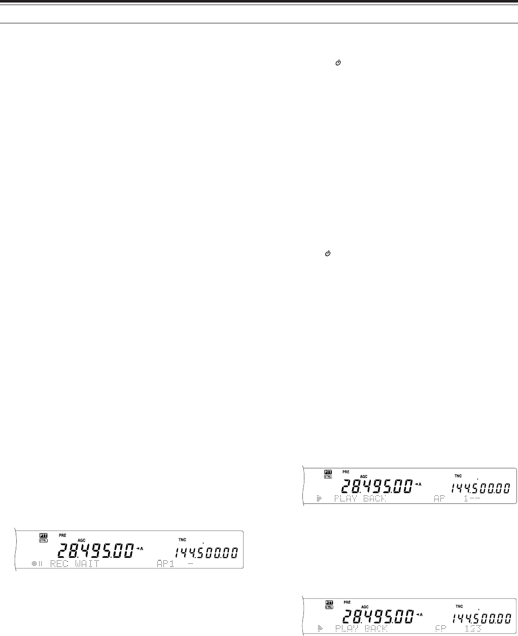
89
15 OPERATOR CONVENIENCES
DRU-3A DIGITAL RECORDING UNIT
(OPTIONAL)
The optional DRU-3A unit allows you to record a
voice message on up to 3 channels. After recording
a message via your transceiver microphone, you can
then send that message.
The maximum recording time for each channel is as
follows:
Channel 1: Approx. 30 seconds
Channel 2: Approx. 15 seconds
Channel 3: Approx. 15 seconds
The DRU-3A is useful in many situations:
• DX chasing or contest operation where repeated
calls are necessary for extended periods of time.
• Checking interference complaints with other
equipment (lets you be in two places at one time).
• Checking or adjusting your transmit signal or your
antenna(s) if it’s not convenient to be sitting in
front of your microphone.
• Helping a friend adjust his/her antenna or receive
when he/she needs repeated test transmissions.
For information on how to install the DRU-3A unit,
refer to “INSTALLING OPTIONS” {page 97}.
RECORDING MESSAGES
This section explains how to record a single
message.
1Select SSB, FM, or AM.
• Use the same mode for transmitting and
receiving.
2If VOX is ON, press [VOX/ LEVEL] to switch the
function OFF.
3Press [FUNC], [1/ CH1/REC] to record the
message for channel 1.
•“¡|| REC WAIT” and “AP1 –” appear.
• To exit the Record Standby mode and quit
recording your message, press [CLR].
4Press and hold [1/ CH1/REC], then begin
speaking into your microphone.
• Three channels are available for recording
messages. Press channel key [2/ CH2/REC]
or [3/ CH3/REC] in place of [1/ CH1/REC], in
step 3, to record the message on a different
channel.
5Release the key pressed in step 4 when you have
finished recording your message.
• Also when the maximum recording time
passes, recording stops.
• The content of the channel is overwritten with
the new message.
6Repeat steps 3 to 5 to record a message on
another channel.
Note: Pressing [ ] (POWER) cancels recording in progress and
clears the memory channel.
MESSAGE PLAYBACK
You can play back the message in channel 1, 2, or 3
to check or to send. It is also possible to make a
longer message, by consecutively playing back the
messages of more than one channel, linking them
together.
You can even repeatedly send a longer, linked
message by using the Repeat function. To switch this
function ON, access Menu No. 29A and select ON
(Default is OFF). Then, select the repeat interval
time in Menu No. 29B (Default is 10 seconds).
Note:
◆
Pressing [ ] (POWER) cancels playback in progress.
◆
The settings in Menu Nos. 29A and No. 29B are shared with CW
Message Playback described in “CW MESSAGE MEMORY”
{page 43}.
■Checking Messages
1Select SSB, FM, or AM.
• Use the same mode for transmitting and
receiving.
2If VOX is ON, press [VOX/ LEVEL] to switch
the function OFF.
3Press [1/ CH1/REC], [2/ CH2/REC], or
[3/ CH3/REC], depending on which channel
you want to check.
• For example, “s PLAY BACK” and “AP 1– –”
appear while playing back the message in
channel 1.
• To interrupt playback, press [CLR].
4To play back another message in sequence,
press the corresponding key ([1/ CH1/REC],
[2/ CH2/REC], or [3/ CH3/REC]) while the first
message is being played.
• Up to three channels can be queued.

90
15 OPERATOR CONVENIENCES
■Sending Messages
1Select SSB, FM, or AM.
• Use the same mode for transmitting and
receiving.
2Press [VOX/ LEVEL] to switch VOX ON or
OFF.
• If you switched VOX ON, skip step 3.
3Press [SEND], or press and hold Mic [PTT].
4Press [1/ CH1/REC], [2/ CH2/REC], or
[3/ CH3/REC], depending on which channel
you want to use.
• For example, “s PLAY BACK” and “AP 1– –”
appear while playing back the message in
channel 1.
• To interrupt playback, press [CLR].
5To play back another message in sequence,
press the corresponding key ([1/ CH1/REC],
[2/ CH2/REC], or [3/ CH3/REC]) while the first
message is being played.
• Up to 3 channels can be queued.
6If you pressed [SEND] or Mic [PTT] in step 3,
press [SEND] again or release Mic [PTT].
■Erasing a Recorded Message
1Press [FUNC] then [1/ CH1/REC] or
[2/ CH2/REC] or [3/ CH3/REC] to select the
message which you want to erase.
•“¡|| REC WAIT” and “APn –” appear, where
“n” represents the channel number.
2To erase the recorded message, press and
hold the same key as in step 1 ([1/ CH1/REC],
[2/ CH2/REC], or [3/ CH3/REC]), and press
[CLR] at the same time.
• A beep sounds and the message is erased.
■Changing Inter-message Interval Time
For repetitive message playback, you can change
the interval between each series of messages.
Use Menu No. 29B, and select the time in the
range of 0 to 60 seconds.
■Changing Playback Volume
Turning the MAIN AF or SUB AF control does not
change the volume for playback. To change the
volume, access Menu No. 14 to select the
playback volume level from OFF and 1 to 9.

91
15 OPERATOR CONVENIENCES
VS-3 VOICE SYNTHESIZER (OPTIONAL)
Install the optional VS-3 unit to use this function.
Each time you change the transceiver mode such
as VFO A/B or Memory Recall, the transceiver
automatically announces the new mode. In
addition, you can program the front panel [PF] key
so that pressing it makes the transceiver announce
the displayed information. If you have the optional
MC-47 microphone, you can program one of the
Mic [PF] keys for this function as well.
For an explanation on how to install the VS-3 unit,
refer to “INSTALLING OPTIONS” {page 97}.
The table below indicates what the transceiver
automatically announces when it changes the settings.
desserPyeK noitarepO tnemecnuonnA
]B/A[ AOFV
ycneuqerf+OFV
BOFV
]–[,]+[ egnahcdnaB
]LLAC[ lennahcllaCycneuqerf+llaC
]M/OFV[ roOFV yromeM llaceR
ycneuqerf+OFV ro .oNyromeM+RM ycneuqerf+
]UNEM[ /
]–[,]+[ .oNuneM noitceles
+.oN+uneM /rebmundetceleS retemarap
]NI.M[ yromeM edomllorcS
+lennahC+RM )tigid-3(.oNyromeM ycneuqerF+
]TNE[ ycneuqerF yrtne retnE
HC/ITLUM lortnoc
.oNuneM segnahc
+.oN+uneM /rebmundetceleS retemarap
yromeM .oNlennahc segnahc
yromeM+RM +.oNlennahc ycneuqerf
yekciremuN yrtne gniretnE srebmun rebmunyrevE deretne
]•[ ehtgniruD ycneuqerf yrtne ztrehageM
Note: The PF key assignment parameter is announced as the
number shown below.
rebmununeM361ECIOV462ECIOV56INOMXR
66INOMPSD76RMKCIUQ86NI.MKCIUQ96TILPS
07TES-FT17B/A27M/OFV37B=A
47NACS57OFV>M67NI.M77ENUTWC
871HC972HC083HC18ENIF
28RLC38LLAC48LRTC58zHM1
682/1TNA78BN88.R.N98.C.B
09.N.A99FFO
For the [PF] key, the transceiver will announce
different information, depending on whether VOICE1
or VOICE2 is selected.
VOICE1:
• VFO or memory channel frequencies are
announced beginning with the 10 MHz digit and
continuing through to the 10 Hz digit. If the
memory channel has no data stored, “open” is
announced. For the MHz decimal point, “point” is
announced. For the kHz decimal point, a short
pause (200 ms) is made. A 200 ms pause is also
made between the channel number and the
frequency.
• Menu numbers and their settings are announced
with a short pause (200 ms) between the menu
number and the setting.
Note: If operating a key or a control changes the contents of the
display while an announcement is in progress, the announcement is
interrupted.
VOICE2:
• The S-meter readings at the time you pressed the
key, are announced, for example, “S5” or “20 dB”.
The table below shows the available announcements
when the [PF] (VOICE2) is pressed.
NIAM BUS
reteM-S leveL -ecnuonnA tnem reteM-S leveL -ecnuonnA tnem
3~11S11S
42S22S
6~53S33S
74S44S
9~85S55S
016S66S
21~117S77S
318S88S
51~419S99S
81~61Bd0101Bd01
02~91Bd0211Bd02
22~12Bd0321Bd03
52~32Bd0431Bd04
82~62Bd0541Bd05
03~92Bd0651Bd06
1Assign VOICE1 (63) or VOICE2 (64) to the front
panel [PF] key by accessing Menu No. 51A. Or, if
you are using the optional MC-47 or MC-52DM
microphone, assign one of the Mic [PF] keys to
either VOICE1 or VOICE2. For programming Mic
[PF] keys, refer to “MICROPHONE PF KEYS”
{page 77}.
2Press the [PF] key that you programmed.
• An announcement is made based on the
VOICE1 or VOICE2 selection.
• To interrupt the announcement, press the [PF]
key again.

92
15 OPERATOR CONVENIENCES
MICROPROCESSOR RESET
If your transceiver seems to be malfunctioning,
resetting the microprocessor default settings may
resolve the problem. There are 2 levels of resetting
the microprocessor of the TS-2000(X): partial reset
and full reset.
INITIAL SETTINGS
For each VFO, the factory defaults for the operating
frequency and mode are as follows:
• MAIN VFO A: 14.000.000 MHz/ USB
• MAIN VFO B: 14.000.000 MHz/ USB
• SUB VFO: 144.000.00 MHz/ FM
The Memory channels and Quick Memory channels
have no data stored.
PARTIAL RESET
Perform a Partial Reset if a key or control does not
function according to the instructions in this manual.
The following data is NOT erased by performing a
Partial Reset.
• Memory channel data
• Menu settings
• Antenna tuner preset data
• ANT 1/ANT 2 data
Reset the transceiver by pressing [A/B]+[ ].
• A confirmatin message appears. Press [A/B] to
proceed. Otherwise, press any other key to
cancel the Partial Reset and return to normal
operation.
• “HELLO” appears on the display and the VFOs
resets to the factory default values.
FULL RESET
Perform a Full Reset if you want to erase all the data
in all the memory channels. In addition, this function
resets all the settings that you customized, to the
factory defaults (i.e.- menu settings, antenna tuner
preset data, etc.).
Reset the transceiver by pressing [A=B]+[ ].
A confirmation message appears when performing
the Full Reset. Press [A=B] to proceed. Otherwise,
press any other key to cancel the Full Reset and
return to normal operation.
When you perform the full reset:
• “HELLO” appears on the display.
• All frequencies, modes, memory data and AT
preset data are set to the factory default values
(refer to “INITIAL SETTINGS”, above).
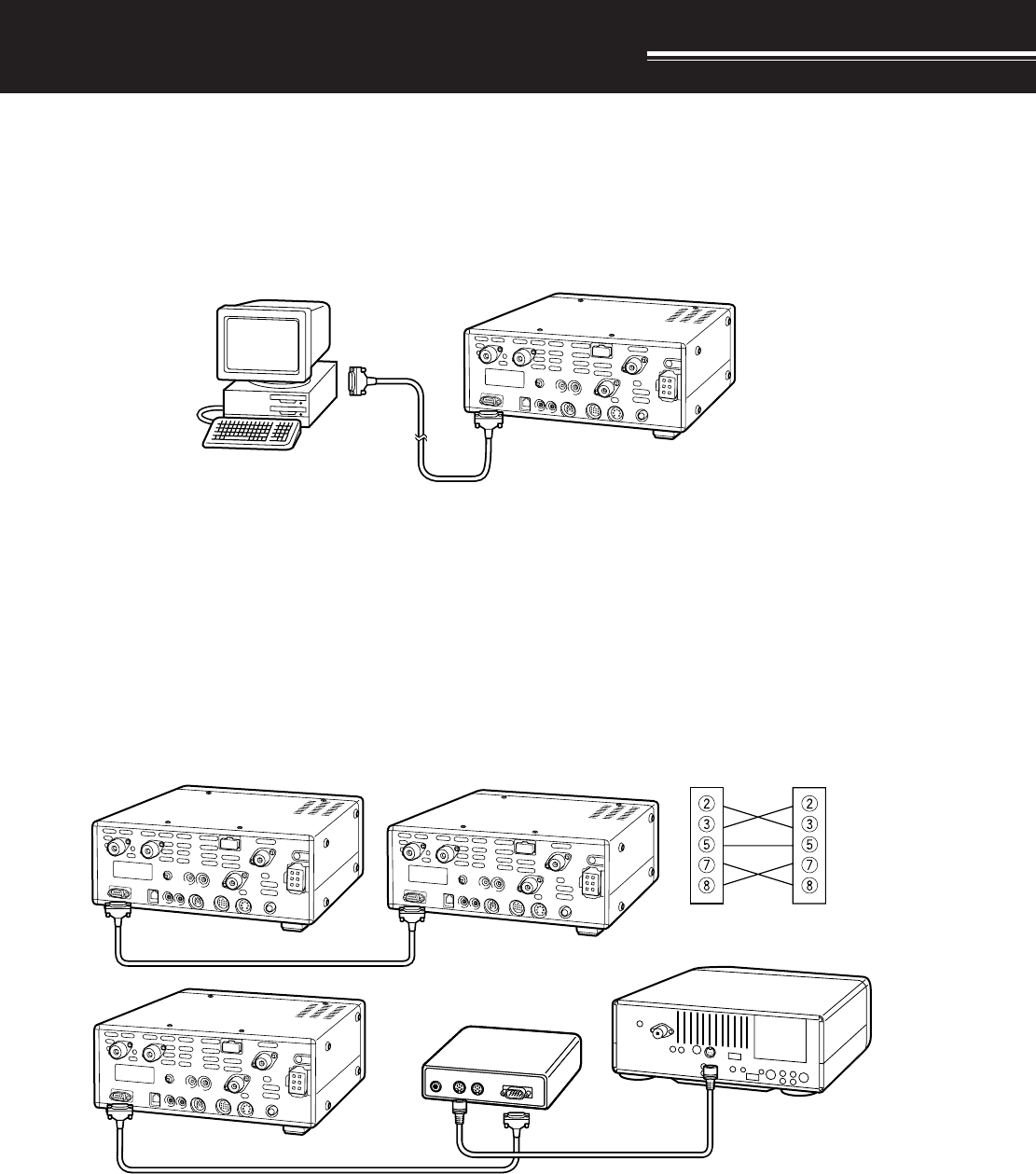
93
CONNECTING PERIPHERAL EQUIPMENT
COMPUTER
The COM connector allows you to directly connect a computer or dumb terminal by using an RS-232C cable
terminated with a 9-pin female connector.
No external hardware interface is required between your computer and the transceiver. See “APPENDIX”
{page 113} for information related to this connector.
COM connector
Personal computer/
dumb terminal
RS-232C
serial port
TS-2000(X)/ TS-B2000
Straight cable
COMPATIBLE TRANSCEIVER
When transferring data to or from another TS-2000(X), TS-570, or TS-870S, directly connect the two transceivers
using the COM connectors.
When transferring data to other KENWOOD transceivers, use the optional IF-232C interface unit. Connect the
IF-232C to the ACC 1 connector located on the compatible transceiver.
TS-2000(X) TS-2000(X)/870S/570
TS-2000(X)
Cross-wired cable
Cross-wired cable
See IF-232C manual.
IF-232C
Straight cable
COM Connector
cable
TS-450S/690S/850S/950SDX
ANT
DIN(6P)
RS-232C(25P)
DIN(6P)
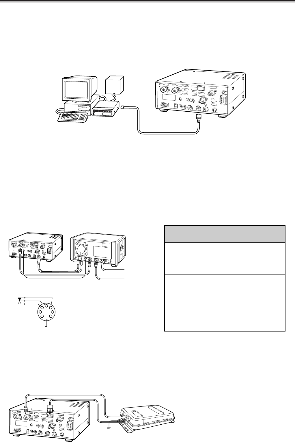
94
16 CONNECTING PERIPHERAL EQUIPMENT
RTTY EQUIPMENT
Use the ACC 2 connector to connect to the RTTY equipment. Connect the RTTY key output line to pin 2 of the
ACC 2 connector. Connect the demodulation input line of the RTTY equipment to pin 3 of the ACC 2 connector
{page 95}.
Note: Do not share a single power supply between the transceiver and the RTTY equipment. Keep as wide a separation as possible between the
transceiver and the RTTY equipment to reduce noise-pickup by the transceiver.
MCP
power
supply
TS-2000(X) ACC 2
MCP
Personal computer/
dumb terminal
HF LINEAR AMPLIFIER
Connect an external transmit power amplifier to the REMOTE connector (1 male REMOTE connector
(E07-0751-XX) is supplied). Switch ON the linear amplifier control relay via Menu No. 28A.
The TX/RX relay response time is 10 ms when you have selected CW Full Break-in and 25 ms when you have
selected CW Semi Break-in.
Note: The TX/RX control method differs, depending on external amplifier models. Some amplifiers enter the TX mode when the control terminal is
grounded. For those amplifiers, connect pin 2 of the REMOTE connector to the GND terminal of the amplifier and connect pin 4 of the connector to
the control terminal of the amplifier.
2
4
1
67
3
5
TS-2000(X)/ TS-B2000
AC LINE
RF OUTPUT
Linear amplifier
Control relay
R
T
GND
REMOTE Connector
(Rear panel view)
REMOTE connector
Pin
No. Function
Speaker output
Common terminal
Standby; when grounded, the
transceiver enters TX mode.
When connected with the common
terminal, the amplifier enters TX mode.
When connected with the common
terminal, the amplifier enters RX mode.
ALC input from amplifier
Approx. +12 V DC is output when in
TX mode (10 mA max.).
1
2
3
4
5
6
7
ANTENNA TUNER
Use the ANT 1 and AT connectors to connect an external antenna tuner. If you connect the external tuner to the
ANT 2 connector, the external tuner will not function.
Note: While using an external antenna tuner with the TS-2000(X)/ TS-B2000, you cannot use the 6 m band to transmit. Connect your 6 m band
antenna to the ANT 2 connector.
TS-2000(X)/TS-B2000
External antenna tuner
The AT-300 external antenna tuner is a
discontinued model. It may no longer be
available in your area.

95
16 CONNECTING PERIPHERAL EQUIPMENT
MCP AND TNC
Use the ACC 2 connector to connect the input/output lines from a Terminal Node Controller (TNC) for Packet
operation, a Multimode Communications Processor (MCP) for operation on Packet, PacTOR, AMTOR, G-TORTM,
PSK31, or FAX, or from a Clover interface. Also use the ACC 2 connector to connect SSTV and phone patch
equipment (1 male ACC2 connector (E07-1351-XX) is supplied).
• Connect the TNC or MCP to the ACC 2 connector using a cable equipped with a 13-pin DIN plug.
• Connecting the TNC or MCP to a personal computer or dumb terminal requires an RS-232C cable.
Note: Do not share a single power supply between the transceiver and the TNC or MCP. Keep as wide a separation as possible between the
transceiver and the computer to reduce noise-pickup by the transceiver.
13
9101112
56 78
12 34
.oNniP niP emaN noitcnuF
1ONAS
reviecer-busehtmorftuptuoFA .noitarepolatigidrofnipatadeviecerPCMroCNTehtottcennoC• .gnitteslortnocFABUSmorftnednepednisileveltuptuoFA• .eulavD05.oNuneMehtgnitsujdaybdegnahcebnacleveltuptuoFA• k01.xorppA:ecnadepmituptuO• Ω.
2YTTRtupniyekYTTR
3ONAM
reviecsnartniamehtmorftuptuoFA .noitarepolatigidrofnipatadeviecerPCMroCNTehtottcennoC• .gnitteslortnocFANIAMehtmorftnednepednisileveltuptuoFA• .eulavC05.oNuneMehtgnitsujdaybdegnahcebnacleveltuptuoFA• k01.xorppA:ecnadepmituptuO• Ω.
4DNGdnuorG
5QSM
lortnochcleuqsreviecsnartniaM .noitarepolatigidrofniplortnochcleuqsPCMroCNTehtottcennoC• .neposihcleuqsreviecsnartehtelihwgnittimsnartmorfCNTehtstneverP• ecnadepmiwoL:nepohcleuqS• ecnadepmihgiH:desolchcleuqS•
6CNnoitcennocoN
7QSS
lortnochcleuqsreviecer-buS .noitarepolatigidrofniplortnochcleuqsPCMroCNTehtottcennoC• .neposihcleuqsreviecsnartehtelihwgnittimsnartmorfCNTehtstneverP• ecnadepmiwoL:nepohcleuqS• ecnadepmihgiH:desolchcleuqS•
8DNGdnuorG
9SKP
lortnocenilTTPreviecsnarT .timsnartotlanimretsihtdnuorG• .noitarepolatigidrofnipgnihctiwseviecer/timsnartPCMroCNTehtottcennoC• .stimsnartreviecsnartehtnehwsetumtupnioiduaenohporciM•
01CNnoitcennocoN
11DKP tupnioiduaenohporciM .noitarepolatigidrofnipatadtimsnartPCMroCNTehtottcennoC•
21DNGdnuorG
31SS
lortnocTTP .timsnartotlanimretsihtdnuorG• .)kcajCIMhtiwlellarapni(rellortnoclanretxerehtorohctiwstoofagnitcennocroF• .stimsnartreviecsnartehtnehwetumTONseodtupnioiduaenohporciM•
ACC2
Front view
(Rear panel)
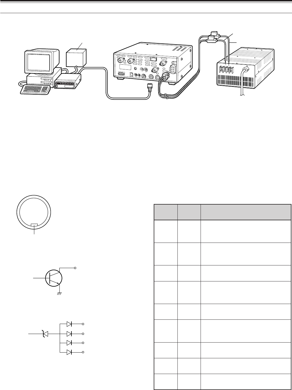
96
16 CONNECTING PERIPHERAL EQUIPMENT
q
r wt
e
u
GND
i
yEXT.CONT
Front view
(Rear panel)
B
C
E
TXC
Circuit of each TXC (pin 1, 2, 4, and 6)
Circuit of ALC inputs (pin 3, 5, 7, and 8)
(20 V DC, 20 mA max.)
pin 3
pin 5
pin 7
pin 8
.oNniP niP emaN noitcnuF
1CXT34 reviecsnartehtnehwdednuorG zHM044/034ehtnostimsnart ).xamAm02,V02CD(.dnab
2CXT05 reviecsnartehtnehwdednuorG .dnabzHM05ehtnostimsnart ).xamAm02,V02CD(
3CLA reifilpmamorftupniCLAzHM05 .)V7–(
4CXT21 reviecsnartehtnehwdednuorG .dnabzHG2.1ehtnostimsnart ).xamAm02,V02CD(
5CLA morftupniCLAzHM)044(034 .)V7–(reifilpma
6BXT41 reviecsnartehtnehwdednuorG .dnabzHM441ehtnostimsnart ).xamAm02,V02CD(
7CLA reifilpmamorftupniCLAzHG2.1 .)V7–(
8CLA morftupniCLAzHM441 .)V7–(reifilpma
lateM revoc DNGdnuorG
TYPICAL MCP/ TNC SETUP
TNC/MCP
TS-2000
TS-2000X
TS-2000B PS-53
LINEAR AMPLIFIER (50 MHz, VHF, UHF and 1.2 GHz)
Connect an external 50 MHz/ VHF/ UHF/ 1.2 GHz power amplifier control cable to the EXT.CONT connector
(1 male EXT.CONT connector (E07-0851-XX) is supplied). The TX/RX switching time can be configured
independently for each band, accessing Menu Nos. 28B ~ 28E. Select 1 for 10 ms delay or 2 for 25 ms delay.
However, when CW Full Break-in is enabled, 10 ms switching delay is applied automatically regardless of the
settings. You can also disable the EXT.CONT control, selecting OFF (default).
Note: The TX/RX control method differs, depending on external amplifier models. Most amplifiers enter the TX mode when the control
terminal is grounded. For those amplifiers, connect the metal cover of the EXT.CONT connector to the GND terminal of the amplifier and
connect pin 2 (50 MHz), pin 6 (144 MHz), pin 1 (430/ 440 MHz), or pin 4 (1.2 GHz) of the connector to the control terminal of the amplifier.
Personal computer
Power supply for
TNC/ MCP
Power supply
for TS-2000(X)/
TS-B2000
Red
Black
EXT.CONT connector
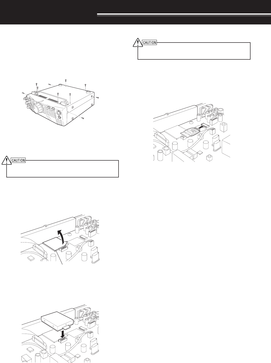
97
INSTALLING OPTIONS
You will require a Phillips screwdriver when installing
the optional units.
REMOVING THE BOTTOM CASE
When installing the optional DRU-3A or VS-3 unit,
remove the bottom case first.
1Remove the 10 screws.
2Lift off the bottom case.
DRU-3A DIGITAL RECORDING UNIT
SWITCH OFF THE POWER AND UNPLUG THE DC POWER
CABLE BEFORE BEGINNING INSTALLATION.
1Remove the bottom case (10 screws).
2Locate the DRU-3A connector.
3Peel off the paper on the cushion attached to the
PC board of the transceiver.
4Plug the DRU-3A into the DRU-3A connector of
the PC board.
5Press the top of the DRU-3A to affix it to the
cushion.
DRU-3A
6Replace the bottom case (10 screws).
Note: After the installation, you can adjust the DRU-3A playback
volume by selecting Menu No. 14.
VS-3 VOICE SYNTHESIZER UNIT
SWITCH OFF THE POWER AND UNPLUG THE DC POWER
CABLE BEFORE BEGINNING INSTALLATION.
1Remove the bottom case (10 screws).
2Locate the VS-3 jack.
3Hold the VS-3 unit with the component side facing
up, and insert the VS-3 connector into the VS-3
jack.
4Replace the bottom case (10 screws).
Note: After the installation, you can adjust the VS-3 playback volume
by selecting Menu No. 15.
Cushion
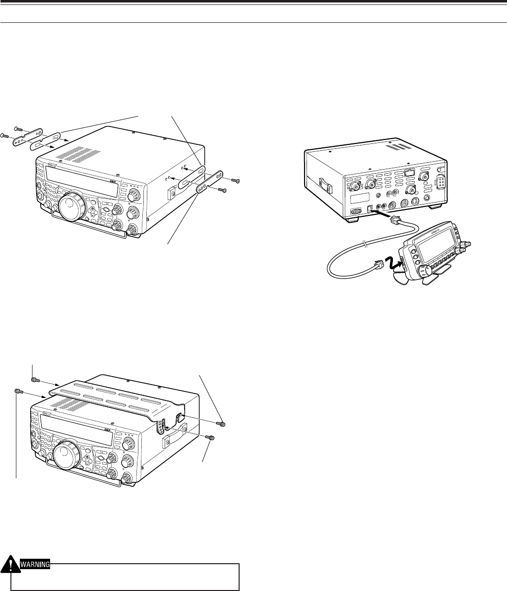
17 INSTALLING OPTIONS
98
MB-430 MOBILE BRACKET
When installing the MB-430, attach the supplied
plastic spacers (G11-2698-XX) to the transceiver in
advance. This is necessary to protect the
TS-2000(X)/ TS-B2000 transceiver from scratches.
Once the bracket is installed onto the vehicle,
prepare the transceiver by loosely screwing in the
rear screws. Hook those screws onto the rear guide
rail of the mounting bracket then adjust the
transceiver to your desired angle before tightening
the screws. Insert and tighten the front screws to
secure the transceiver in place.
To remove the transceiver from the bracket, first
remove the front screws, then loosen the rear screws
slightly and pull the transceiver forward to unlatch it
from the bracket.
Do not install the transceiver so that it is vertically on its side.
RC-2000 REMOTE PANEL
Plug the modular cable from the RC-2000 into the
PANEL connector on the TS-2000(X)/ TS-B2000 rear
panel. Access Menu Nos. 58 ~ 60 to adjust the panel
configuration if necessary.
TS-2000/ TS-2000X
TS-B2000
Rear screw Rear screw
Front screw
Front screw
Make sure the tab faces out
G11-2698-XX

99
TROUBLESHOOTING
Note:
◆
Record the date of purchase, serial number and dealer from
whom the transceiver was purchased.
◆
For your own information, retain a written record of any
maintenance performed on the transceiver.
◆
When claiming warranty service, please include a photocopy of
the bill of sale, or other proof-of-purchase showing the date of
sale.
CLEANING
The keys, controls and case of the transceiver are
likely to become soiled after extended use. Remove
the controls from the transceiver and clean them with
a neutral detergent and warm water. Use a neutral
detergent (no strong chemicals) and a damp cloth to
clean the case.
LITHIUM BATTERY
This transceiver uses an EEPROM to store memory
channel data, menu configurations and all necessary
operation parameters. So, you never have to worry
about replacing batteries to operate the transceiver.
However, the transceiver’s built-in TNC requires a
lithium battery (CR-2032) to store the TNC data.
Battery lifetime varies, but under normal operating
conditions, it should last for approximately 5 years.
If you find that the TNC no longer stores the TNC
parameters, contact an authorized KENWOOD
service center for replacing the lithium battery.
DEMONSTRATION MODE
The transceiver can be configured to enter the
demonstration mode for display purposes. To enter
the demonstration mode:
1Switch the transceiver OFF.
2Press [FUNC]+[ ] to switch the transceiver ON.
• On the dot-matrix display windows, you will see
a few killer whales jump across the display.
You will also notice the display brightness
changes and LEDs turn ON and OFF
automatically.
• If you operate the transceiver while in the
demonstration mode, the demonstration is
temporarily paused. But, if no operation is
performed for more than 10 seconds, the
demonstration starts again.
3To exit the demonstration mode, first turn the
transceiver OFF, then press [FUNC]+[ ] to turn
the transceiver ON.
Note: You cannot exit the demonstration mode by simply switching
the transceiver OFF or performing a full reset {page 92}. You must
switch the transceiver OFF then press [FUNC]+[ ] to turn the
transceiver ON in order to exit the demonstration mode.
GENERAL INFORMATION
Your transceiver has been factory aligned and tested
to specification before shipment. Under normal
circumstances, the transceiver will operate in
accordance with these operating instructions. All
adjustable trimmers, coils and resistors in the
transceiver were preset at the factory. They should
only be readjusted by a qualified technician who is
familiar with this transceiver and has the necessary
test equipment. Attempting service or alignment
without factory authorization can void the transceiver
warranty.
When operated properly, the transceiver will provide
years of service and enjoyment without requiring
further realignment. The information in this section
gives some general service procedures requiring little
or no test equipment.
SERVICE
If it is ever necessary to return the equipment to your
dealer or service center for repair, pack the
transceiver in its original box and packing material.
Include a full description of the problems
experienced. Include both your telephone number
and fax number (if available) along with your name
and address in case the service technician needs to
call for further explanation while investigating your
problem. Don’t return accessory items unless you
feel they are directly related to the service problem.
You may return your transceiver for service to the
authorized KENWOOD dealer from whom you
purchased it or any authorized KENWOOD service
center. A copy of the service report will be returned
with the transceiver. Please do not send
subassemblies or printed circuit boards. Send the
complete transceiver.
Tag all returned items with your name and call sign
for identification. Please mention the model and
serial number of the transceiver in any
communication regarding the problem.
SERVICE NOTE
If you desire to correspond on a technical or
operational problem, please make your note short,
complete, and to the point. Help us help you by
providing the following:
1Model and serial number of equipment.
2Question or problem you are having.
3Other equipment in your station pertaining to the
problem.
4Meter readings.
5Other related information (Menu setup, mode,
frequency, key sequence to induce malfunction,
etc.).
DO NOT PACK THE EQUIPMENT IN CRUSHED
NEWSPAPERS FOR SHIPMENT! EXTENSIVE DAMAGE MAY
RESULT DURING ROUGH HANDLING OR SHIPPING.

100
18 TROUBLESHOOTING
melborP esuaCelbaborP noitcAevitcerroC egaP .feR
tonlliwreviecsnartehT retfapurewop CDV8.31agnitcennoc dnaylppusrewop gnihtoN.][gnisserp ,yalpsidehtnosraeppa siesionreviecerondna .draeh
1
2
3
4
.FFOsiylppusrewopCD .elbacrewopytluaF
detcennoctonsielbacrewopehT .yleruces .neposiesufelbacrewoP
1
2
3
4
.ylppusrewopCDehtNOhctiwS mrifnoC.elbacrewopehttcepsnI .tcerroceraseitiralop )–(evitagen:kcalB;)+(evitisop:deR CDehtotsnoitcennocehtmrifnoC .eruceseraylppusrewop .esufnwolbehtfoesuacehtrofkooL ynagnitcerrocdnagnitcepsniretfA ehtfoesufwenallatsni,smelborp .gnitardeificeps
2
2
2
2
ehtNOgnihctiwsretfA reviecsnarteht,rewop noitcnuftonseod ,elpmaxeroF.yllamron tcerrocnirostigidon ehtnoraeppastigid .yalpsid
1
2
edistuosiegatlovtupniehTV8.31
CD ±%51.)CDV8.51ot7.11(
sahrossecorporcimehT .denoitcnuflam
1
2
ot21aesuroegatlovtupniehttcerroC .yrettabV61
ROSSECORPORCIM“weiveR tahwgnidnatsrednuretfA.”TESER fI.teseRlaitraPaod,tsoleblliwatad .teseRlluFaod,sniamermelborpeht
2
29
ehtNOgnihctiwsretfA lanretnieht,reviecsnart ehtotsteserCNT .seulavtluafedyrotcaf
muihtilpukcabCNTlanretniehT .wolootsiegatlovyrettab ruoyybdellatsniyrettabwenaevaH atarorelaed DOOWNEKDOOWNEK DOOWNEK DOOWNEKDOOWNEK .retneCecivreS 99
seodreviecsnartehT yltcerrocdnopserton yekgnisserpretfa gninrutrosnoitanibmoc snoitcurtsnirepslortnoc .launamsihtni
1
2
3
4
gniebtoneraserudecorP .ylesicerpdewollof sinoitcnufkcoLycneuqerFehT .NO stidnarossecorporcimehT .gnitteserdeenyromem
erareviecsnartehtnosyekehT ehtgnitarepoelihwelbaliavanu .lortnocgninuT
1
2
3
4
SNOITNEVNOCGNITIRW“weiveR .”DEWOLLOF sserP ]CNUF[]CNUF[ ]CNUF[ ]CNUF[]CNUF[ ,]KCOLF/TTA[]KCOLF/TTA[ ]KCOLF/TTA[ ]KCOLF/TTA[]KCOLF/TTA[ ot
.FFOnoitcnufehthctiws ROSSECORPORCIM“weiveR tahwgnidnatsrednuretfA.”TESER fI.teseRlaitraPaod,tsoleblliwatad .teseRlluFaod,sniamermelborpeht neht,lortnocgninuTehtgnitarepopotS .syeketairporppaehtsserp
i
77
29
–
tonnacycneuqerfehT .degnahceb ronoitcnufkcoLycneuqerFehT .NOsinoitcnufllAkcoL sserP ]CNUF[]CNUF[ ]CNUF[ ]CNUF[]CNUF[ ,]KCOLF/TTA[]KCOLF/TTA[ ]KCOLF/TTA[ ]KCOLF/TTA[]KCOLF/TTA[ hctiwsot
.FFOnoitcnufeht sserprO ]CNUF[]CNUF[ ]CNUF[ ]CNUF[]CNUF[ ,]AKCOL/ERP[]AKCOL/ERP[ ]AKCOL/ERP[ ]AKCOL/ERP[]AKCOL/ERP[ ot
.FFOnoitcnufehthctiws
77
77
siytilauqoiduaBSS rohgiheht;roopyrev seicneuqerfoiduawol .tnesbaera
1
2
3
4
siedomnoitarepognorwehT .reviecerehtrofdetceles ehT HTDIW/OLHTDIW/OL HTDIW/OL HTDIW/OLHTDIW/OL rolortnoc
TFIHS/IHTFIHS/IH TFIHS/IH TFIHS/IHTFIHS/IH yltcerrocnisilortnoc
.tes .NOsi2ro1noitcudeResioN
.NOsilecnaCtaeB
1
2
3
4
.edomehtrofBSLroBSUtceleS
ehtnruT HTDIW/OLHTDIW/OL HTDIW/OL HTDIW/OLHTDIW/OL lortnoc ehtdnaesiwkcolcretnuoc TFIHS/IHTFIHS/IH TFIHS/IH TFIHS/IHTFIHS/IH
.esiwkcolclortnoc sserP ]LEVEL/.R.N[]LEVEL/.R.N[ ]LEVEL/.R.N[ ]LEVEL/.R.N[]LEVEL/.R.N[ ehthctiwsot
.FFOnoitcnuf sserP ]LAUNAM/.C.B[]LAUNAM/.C.B[ ]LAUNAM/.C.B[ ]LAUNAM/.C.B[]LAUNAM/.C.B[ ehthctiwsot
.FFOnoitcnuf
82
55
65
65
TROUBLESHOOTING
The problems described in this table are commonly encountered operational malfunctions. These types of
difficulties are usually caused by improper hook-up, accidental incorrect control settings, or operator error due to
incomplete programming. These problems are usually not caused by circuit failure. Please review this table, and
the appropriate section(s) of this instruction manual, before assuming your transceiver is defective.
Note: Placing a powered portable transceiver near this transceiver may cause noise in the transceiver.

101
18 TROUBLESHOOTING
melborP esuaCelbaborP noitcAevitcerroC egaP .feR
eraslangisoN eviecerrodeviecer smeesytivitisnes .roop
1
2
3
4
5
6
ehT LQS .esiwkcolcyllufsilortnoc .NOsinoitcnufrotaunettAehT
]DNES[ ehtdna,desserpsaw .edomtimsnartniwonsireviecsnart ciM,rO ]TTP[ .desserpsi sawhtdiwdnabeviecerehT .tesyltcerrocni
rotcennocannetnagnorwehT .detcelessaw)2TNAro1TNA( .FFOsireifilpmaerpeviecerehT
1
2
3
4
5
6
ehtnruT LQS lortnoc.esiwkcolcretnuoc
sserP ]KCOLF/TTA[ ehthctiwsot
.FFOnoitcnuf sserP ]DNES[ eviecerotnruterot ciMesaelerrO.edom ]TTP[ .
dna”SRETLIFPSD“weiveR RETLIFEVIECEREHTGNIGNAHC“ slortnocehttesdna,”HTDIWDNAB .ylgnidrocca sserP ]CNUF[ ,]2/1TNA/TA[ tcelesot
.rotcennocannetnarehtoeht sserP ]AKCOL/ERP[ ehthctiwsot
.NOnoitcnuf
9175
–
55
27
75
eraslangisoN eviecerrodeviecer smeesytivitisnes siretem-S;roop .elacsllufgnidaer
.woloottessawlortnocFRehTehtnruT NIAGFRNIAM ylluflortnoc
.esiwkcolc 81
slangisdevieceR yllatotera .elbigilletninu
sawedomnoitaludomgnorwehT .detceles sserP ]OTUA/BSU/BSL[ ,
]VER/KSF/WC[ ro, ]RAN/MA/MF[ ot
.edomnoitaludomtcerrocehttceles
91
lliwnacSyromeM .gninnacstratston 1
2
3
4
ehT LQS testonsawlortnoc
.yltcerroc slennahcyromemowtnahtsseL .dekcolnuerew slennahcyromemowtnahtsseL .demmargorperew ehT LQS testonsawlortnoc
.yltcerroc
1
2
3
4
ehttsujdA LQS tsujotslortnoc .esiondnuorgkcabetanimile .slennahcyromemowttsaeltakcolnU
yromemowttsaeltaniataderotS .slennahc ehttsujdA LQS .slortnoc
64,91
86
86
64,91
lliwnacSyromeM ehtfoenonacston eht;slennahcderots silennahcderised .tuodekcolTON
lennahceht,detcelesnacSpuorGhtiW .puorgtnereffidanisinacsottnawuoy yromemehtsniatnoctahtpuorgehttceleS .nacsottnawuoylennahc 96
lliwnacSmargorP .gninnacstratston eraseicneuqerfdnednatratsehT .lacitnedi .seicneuqerfdnednatratstnereffiderotS26
tonseodgninuT .yllufsseccushsinif dnaelbaclaixaocehtfoecnadepmiehT .dehctamtonsawannetna hsinifyllufsseccustonseodgninuT ehthguohtlasnoitidnocnognidneped .1:3nahtrellamssetacidniretemRWS
ehtrewolotmetsysannetnaehttsujdA .RWS 1
sirenutlanretniehT dessapyb retfayletaidemmi .detratssigninut
ootsimetsysannetnaehtfoRWSehT .hgih ehtrewolotmetsysannetnaehttsujdA .RWS 1
timsnarttonnacuoY uoyhguohtneve ciMsserp ]TTP[ ro tlusersnoissimsnart .stcatnoconni
1
2
3
4
5
tonsawgulpenohporcimehT CIMehtotniyletelpmocdetresni .rotcennoc .NOsinoitcnuftibihnItimsnarTehT fodaetsnidetcelessawKSFroWC .edomeciova sawhtdiwdnabretlifXTPSDehT .detcelesylreporpni rotcennocannetnagnorwehT .detcelessaw)2TNAro1TNA(
1
2
3
4
5
CIMehterusne,rewopehtFFOnruT ,tinistcejbongierofonsahrotcennoc .ylmrifrotcennocehtnigulpneht .FFOot45.oNuneMegnahC sserP ]OTUA/BSU/BSL[ ro
]RAN/MA/MF[ .edomeciovatcelesot .22.oNuneMnisgnittesehttsujdA
sserP ]CNUF[ ,]2/1TNA/TA[ tcelesot
.rotcennocannetnarehtoeht
3
1491
14
27

102
18 TROUBLESHOOTING
melborP esuaCelbaborP noitcAevitcerroC egaP .feR
otgnitpmettA nistlusertimsnart ”OLLEH“eht gniraeppaegassem eviecerehtdna gniebedom .derotser
1
2
3
4
detcennoctonsiannetnaehT .yltcerroc dnaannetnaehtfosecnadepmiehT ylreporptonerareviecsnart .dehctam V8.31edistuosiegatlovtupniehTCD ±.)CDV8.51ot7.11(%51 rewopCDehtfognitartnerrucehT .hguonetonsiylppus
1
2
3
4
.noitcennocannetnaehtkcehC .yrassecensatcerroC annetnaehtfoRWSehtecudeR .metsys
ot21aesuroegatlovtupniehttcerroC .yrettabV61 asahtahtylppusrewopCDaesU taA5.02nahteromfognitartnerruc .CDV8.31
27
1
2
2
sahreviecsnartehT .rewoptimsnartwol 1
2
.woloottessiniagenohporcimehT
snoitcennocmetsysannetnarooP .RWShgihgnisuacera
1
2
esaercni,edomMAroBSSninehW .niagenohporcimeht .snoitcennocannetnaehtkcehC sirenutannetnaehttahtmrifnoC .RWSwolagnitroper
02
27
tonseodXOV .etarepo .woloottessiniagXOVehT.niagXOVehtesaercnI93
reifilpmaraeniLFH .etarepotonseod 1
2
siyalerlortnocreifilpmaraenilehT .FFO ehT ETOMER signiriwrotcennoc
.ytluafrognorw
1
2
.NOotA82.oNuneMegnahC
ehttcepsnI ETOMER gniriwrotcennoc .yrassecensatcerrocdna
67
49
,zHM441,zHM05 rozHM044/034 raenilzHG2.1 tonseodreifilpma .etarepo
1
2
3
.FFOsilortnocreifilpmaraenilehT sielbaclortnocreifilpmaraenilehT ehtotdetcennoc ETOMER
.rotcennoc ehT TNOC.TXE signiriwrotcennoc
.ytluafrognorw
1
2
3
.NOotE82~B82.soNuneMegnahC ehtotelbacehttcennoC TNOC.TXE
.rotcennoc
ehttcepsnI TNOC.TXE rotcennoc .yrassecensatcerrocdnagniriw
6769
69
sseccatonnacuoY .sretaeperesudna 1
2
roenotbusaeriuqersretaeperynaM .sseccaotenotzH0571
siycneuqerftfihsronoitceridtfihS .gnorw
1
2
”NOITAREPORETAEPERMF“weiveR dnaycneuqerftcerrocehttcelesdna .enotbusfoepyt s’retaeperehtnotimsnarttsumuoY ehtnoeviecerdnaycneuqerftupni otrefeR.ycneuqerftuptuos’retaeper .”NOITAREPORETAEPERMF“
23
23
noitarepolatigiD onrowefnistluser stcatnocrostcennoc .snoitatsrehtohtiw
1
2
3
4
5
ehtneewtebsnoitcennoclacisyhP dna,retupmoc,reviecsnart erawtfosro,tcerrocnisiPCM/CNT .gnorweraPCM/CNTehtnisgnittes eviecerdnatimsnarttnereffiD .desugnieberaseicneuqerf
reviecsnartehtneewtebslevelehT .tcerrocnieraPCM/CNTehtdna
ehtrolangisdettimsnartruoY .kaewootsilangiseviecergnimocni ruoyniretemarapemityaledXTehT .tesyltcerrocnisawPCM/CNT
1
2
3
4
5
sihtgnisusnoitcennocllakcehc-eR dna,launamPCM/CNTruoy,launam salaunamerawdrahretupmocruoy .secnerefer snoitcnufTIXdnaTIRehttahtmrifnoC uoytahtmrifnoC.FFOdehctiwsera .ycneuqerftilpsgnitarepoTONera uneMgnisuslevelXRdnaXTtsujdA noslortnocleveldna,D05~B05.soN .PCM/CNTruoy roannetnaruoyetacoler/tneiroeR .niagannetnaruoyesaercni otemityaledXTPCM/CNTehtteS .sm003nahterom
59,49
04,83
05
–
–
tastpmettA ehtgnillortnoc ehthtiwreviecsnart evahretupmoc .deliaf
1
2
stcennoctahtelbacehthtiwmelborP .0002B-ST/)X(0002-STehtotCPeht ruoynitessretemarapnoitacinummoC hctamtonodmargorplanimret .sretemarapreviecsnart
1
2
elbacdnaelbacehtkcehC .snoitcennoc ehtnisretemarapemasehtesU .reviecsnartehtdnamargorplanimret .65.oNuneMehtkcehC
39
18

103
18 TROUBLESHOOTING
OPERATION NOTICES
The TS-2000(X)/ TS-B2000 has been designed and
engineered to avoid possible hardware glitches.
However, you may notice the following symptoms
when you operate the transceiver. These symptoms
are not malfunctions.
DC POWER SUPPLY
As stated in the SPECIFICATIONS {page 105}, this
transceiver requires a supplied DC voltage source of
13.8 V ±15%. If you find that the transceiver cannot
be switched ON, or that is shut OFF automatically,
the DC voltage may be outside the specified range.
In such a case, remove the DC cable from the
transceiver immediately and confirm that the supplied
voltage is within the specified range.
TX SIGNAL HARMONICS
The TS-2000(X)/ TS-B2000 has 2 independent
receivers. Thus, it can receive signals while you are
transmitting. Because of this, the harmonics or the
mixed heterodyne signal images of your transmission
signal can be monitored through the receiver. Even if
the TX Monitor function {page 79} is OFF, the
transmission signal may be monitored through the
speaker.
INTERNAL BEATS
On some spots of the transceiver bands, the S-meter
moves or you cannot receive any signals. This is
inevitable when you use superheterodyne receivers.
You may notice the signals on the following spots of
the bands.
On the main transceiver:
51.259 MHz, 430.151 MHz, 432.209 MHz,
436.799 MHz, 439.298 MHz, 442.440 MHz
(K-type only), 1247.999 MHz, and 1269.387 MHz.
When the sub-receiver frequency is 144.000 MHz:
146.663 MHz (K-type only) and 436.249 MHz.
When the sub-receiver frequency is 440.000 MHz:
437.333 MHz and 444.315 MHz (K-type only).
Note: When the sub-receiver frequency changes, the above beat
frequencies may be changed accordingly. In this case, turn the
sub-receiver OFF to remove the internal spurious signals.
On the sub-receiver:
144.490 MHz, 144.945 MHz, 430.150 MHz,
436.210 MHz, 436.800 MHz, 442.020 MHz
(K-type only), 449.400 MHz (K-type only) and
429.050 MHz (K-type only).
VISUAL SCAN
When you have the same VHF band or UHF band
for both the main transceiver and the sub-receiver,
the Visual scan may indicate the signals on the
bar-graph display even if no signal is monitored on
the main transceiver. This error occurs due to the
internal spurious harmonics that are generated by
the sub-receiver. Refer to “INTERNAL BEATS”,
above, for the frequencies.
SENSITIVITY (K-type only)
While the main transceiver is receiving on the VHF band
(142 ~ 152 MHz), the sensitivity of the main transceiver
slightly degrades when you select 118 ~ 136 MHz or
155 ~ 300 MHz for the sub-receiver.
AGC
When you turn the AGC function OFF {page 38}, the
receiving audio signals can be distorted. In this case,
decrease the RF GAIN, turn the pre-amplifier OFF, or
turn the attenuator ON. In general, the RF GAIN is
greatly reduced when the AGC is turned OFF.
SUB-RECEIVER
When you turn the sub-receiver ON or OFF, a
popping noise may be monitored from the speaker.

104
OPTIONAL ACCESSORIES
PS-53
Regulated DC Power
Supply (22.5 A)
MC-43S
Hand Microphone
MC-47
Multi-function Microphone
HS-6
Small Headphones
SP-23
External Speaker
SP-50B
Mobile Speaker
MB-430
Mobile Mounting Bracket
HS-5
Deluxe Headphones
DRU-3A
Digital Recording Unit
VS-3
Voice Synthesizer Unit
LF-30A
Low-pass Filter
PG-2Z
DC Cable
MC-60A
Deluxe Desktop
Microphone
MC-90
DSP-compatible Desktop
Microphone
MC-80
Desktop Microphone
Microphone sensitivity is low in FM mode.
MC-52DM
DTMF Microphone
UT-20
1.2 GHz TX/ RX unit
RC-2000
Mobile Controller
Service center installation only. Contact
an authorized dealer for details.
See page 98 for the installation.
ARCP-2000
Advanced Radio Control
Program
This option is supplied with the TS-B2000.
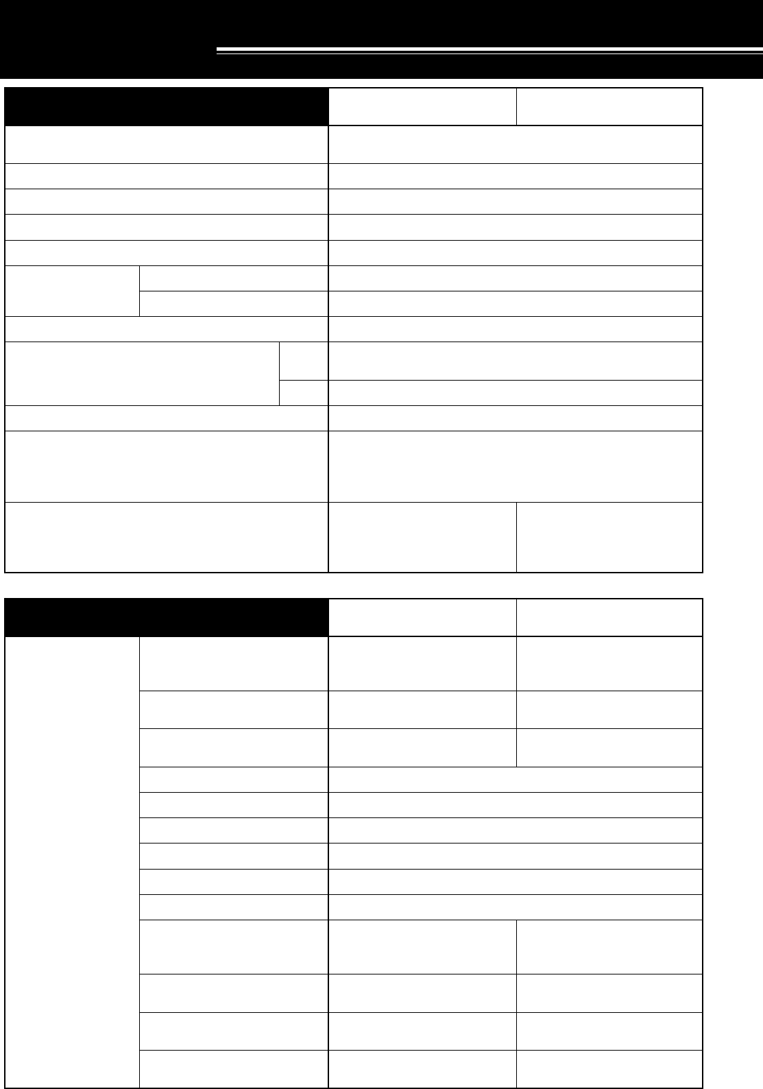
105
SPECIFICATIONS
lareneG 0002-ST
0002B-ST X0002-ST
edoM /)MF(E3F/)MA(E3A/)WC(A1A/)BSU,BSL(E3J
)D2F(D2F/)KSF(D1F
slennahcyrome
mforebmuN003
ecnadepmiannetnA05Ω051~7.61renuTannetnAhtiw( Ω)
egatloVylppuSV8.31CD ±%51
dohtemgnidnuorGdnuorgev
itageN
tnerruC ).xam(timsnarTsselroA5.02
)langison(evieceRsselroA6.2
egnarerutarepmetelbasU01– °05~C °41+(C °22
1~F °)F
01–(ytilibatsycneuqerF °05~C °)C niaM nihtiwedomXTMF ±01x5.0
6–
±zHk2
nihtiwedomrehtO ±01x5.0
6–
(±)mpp5.0
buSnihtiW ±01x5.0
6–
±zH006
)erutarepmetmoorta(ycaruccaycneuqerFnihtiW ±mpp5.0
)dedulcnisnoitcejorPDxHxW(snoisnemiD
ni16.41xni1
2.4xni60.11/mm173x701x182
)X0002-ST/0002-ST(
ni65.31xni12.4xni60.11/mm5.443x701x182
)0002B-ST(
thgieW
bl2.
71/gk8.7.xorppA
)0002-ST(
bl6.61/gk5.7.xorppA
)0002B-ST(
bl1.81/gk2.8.xorppA
rettimsnarT 0002-ST
0002B-ST X0002-ST
egnarycneuqerF
dnabm061
)epyt-K(zHM0.2~8.1
)epyt-E(zHM0.2~18.1
)epyt-2E
(zHM58.1~38.1
)epyt-K(zHM0.2~8.1
)epyt-E(zHM0.2~18.1
dnabm08 )epyt-K(zHM0.4~5.3
)sepyt-EllA(zHM8.3~5.3
)epy
t-K(zHM0.4~5.3
)sepyt-E(zHM8.3~5.3
dnabm04 )epyt-K(zHM3.7~0.7
)sepyt-EllA(zHM1.7~0.7
)epyt-K(zHM3.7~0.7
)se
pyt-E(zHM1.7~0.7
dnabm03zHM51.01~1.01
dnabm02zHM53.41~0.41
dnabm71zHM861.81~860.81
dnabm51zHM54.12~0.12
dnabm2
1zHM99.42~98.42
dnabm01zHM7.92~0.82
dnabm6
)epyt-K(zHM0.45~0.05
)epyt-E(zHM0.25~0.05
)epyt-2E(zHM2.05~0.05
)e
pyt-K(zHM0.45~0.05
)epyt-E(zHM0.25~0.05
dnabm2 )epyt-K(zHM841~441
)sepyt-EllA(zHM641~441
)epyt-K(zHM841~44
1
)sepyt-E(zHM641~441
dnabmc07 )epyt-K(zHM054~034
)sepyt-EllA(zHM044~034
)epyt-K(zHM054~034
)sepyt-E(zHM044
~034
dnabmc32 zHM0031~0421
)02-TU/w( zHM0031~0421

106
20 SPECIFICATIONS
rettimsnarT 0002-ST
0002B-ST X0002-ST
rewoptuptuO
MF/KSF/WC/BSS
.xaM /)dnabmc07(W05/)dnabm2~m061(W001
)dnabmc
32(W01
.niM /)dnabmc07(W5/)dnabm2~m061(W5
)dnabmc32(W1
MA
.xaM /)dnabmc07(W5.21/)dnabm2~m061(W52
)dnabmc32(W
5.2
.niM /)dnabmc07(W5/)dnabm2~m061(W5
)dnabmc32(W1
noitaludoM
BSSdecnalaB
MFecnatcaeR
MAlevelwoL
snoissimesuoir
upS
dnabm01~m061sselroBd05–
dnabmc07~m6sselroBd06–
dnabmc32sselroBd05–
)BSS(noisserppusreirraCeromroBd05
noiss
erppusdnabedisdetnawnU
)zHk0.1ycneuqerfnoitaludom( eromroBd05
ycneuqerfmumixaM
)MF(noitaived
ediW ±sselrozH
k5
worraN ±sselrozHk5.2
egnarycneuqerftfihsTIX ±zHk0.02
ecnadepmienohporciM006 Ω
revieceR 0002-ST
0002B-ST X0002-ST
epyttiucriC reviecnartniaM enydoretehrepus.vnocelpurdauQ:KSF/MA/WC/BSS
en
ydoretehrepusnoisrevnocelpirT:MF
reviecer-buSenydoretehrepusnoisrevnocelbuoD:MA/MF
egnarycneuqerF
reviecs
nartniaM
)sepytllA(zHM0.06~30.0
)epyt-K(zHM251~241
)sepyt-EllA(zHM641~441
)epyt-K(zHM054~024
)sepyt-EllA(zHM044~034
)02-TU/w(zHM0031~0421
)sepytllA(zHM0.06~30.0
)epyt-K(zHM251~241
)epyt-E(zHM641~441
)epyt-K(zHM054~024
)epyt-E(zHM044~034
)sepytllA(zHM0031~0421
reviecer-buS
)epyt-K(zHM471~811
)sepyt-EllA(zHM641~441
)epy
t-K(zHM215~022
)sepyt-EllA(zHM044~034
)epyt-K(zHM471~811
)epyt-E(zHM641~441
)epyt-K(zHM215~022
)epyt-E(zHM044~034
etaidemretnI
)FI(ycneuqerF
reviecsnartniaM
FIts1
zHM529.57rozHM580.96:zHM06~30.0
zHM598.14:zHM215~8
11
zHM594.531:zHM0031~0421
zHM596.01:FIdn2
zHk554:FIdr3
zHk0.21:FIht4
reviecer-buS zHM525.85:FIts1
zHk554:FI
dn2

107
20 SPECIFICATIONS
revieceR 0002-ST
0002B-ST X0002-ST
ytivitisneS
KSF/WC/BSS
)Bd01N/S(
niaM
4:zHM507.1~5.0 μsselroV
2.0:zHM5.42~50
7.1 μsselroV
31.0:zHM0.03~5.42 μsselroV
31.0:zHM0.45~0.05 μsselroV
11.0:zHM641~441 μ)sepyt-EllA(sselroV
61.0:
zHM841~441 μ)epyt-K(sselroV
11.0:zHM044~034 μ)sepyt-EllA(sselroV
11.0:zHM054~034 μ)epyt-K(sselroV
11.0:zHM0
031~0421 μ)sepytllA(sselroV
MA
)Bd01N/S(
6.13:zHM507.1~5.0 μsselroV
0.2:zHM5.42~507.1 μsselroV
3.1:zHM0.03~5.
42 μsselroV
3.1:zHM0.45~0.05 μsselroV
0.1:zHM641~441 μ)sepyt-EllA(sselroV
4.1:zHM841~441 μ)epyt-K(sselroV
0.1
:zHM044~034 μ)sepyt-EllA(sselroV
0.1:zHM054~034 μ)epyt-K(sselroV
0.1:zHM0031~0421 μ)sepytllA(sselroV
MF
)DAN
ISBd21(
22.0:zHM0.03~0.82 μsselroV
22.0:zHM0.45~0.05 μsselroV
81.0:zHM641~441 μ)sepyt-EllA(sselroV
52.0:zHM8
41~441 μ)epyt-K(sselroV
81.0:zHM044~034 μ)sepyt-EllA(sselroV
81.0:zHM054~034 μ)epyt-K(sselroV
81.0:zHM0031~
0421 μ)sepytllA(sselroV
MA
)Bd01N/S(
buS
55.1:zHM641~441 μ)sepyt-EllA(sselroV
52.2:zHM841~441 μ)epyt-K(sselro
V
55.1:zHM044~034 μ)sepyt-EllA(sselroV
55.1:zHM054~834 μ)epyt-K(sselroV
MF
)DANISBd21(
82.0:zHM641~441 μ)sepy
t-EllA(sselroV
04.0:zHM841~441 μ)epyt-K(sselroV
82.0:zHM044~034 μ)sepyt-EllA(sselroV
82.0:zHM054~834 μ)epyt
-K(sselroV
ytivitceleS
BSS
/zH003:tuc-woL(
)zH0062:tuc-iH
niaM
zHk4.4:Bd06–,zHk2.2:Bd6–
MA
/zH001:tuc-woL(
)zH
0003:tuc-iH
zHk0.21:Bd05–,zHk0.6:Bd6–
MFzHk0.52:Bd05–,zHk0.21:Bd6–
MA buS zHk0.52:Bd05–,zHk0.21:Bd6–
MFzHk0.5
2:Bd05–,zHk0.21:Bd6–
noitcejeregamI reviecsnartniaMeromroBd07
reviecer-buSeromroBd06
noitcejerFIts1 reviecsn
artniaMeromroBd07
reviecer-buSeromroBd06
)zHk1ta(noitaunettaretlifhctoNeromroBd03
)zHk1ta(noitaunettalecnac
taeBeromroBd04
egnarycneuqerftfihsTIR ±zHk0.02

108
20 SPECIFICATIONS
revieceR 0002-ST
0002B-ST X0002-ST
ytivitisneshcleuqS
MA/KSF/WC/BSS
niaM
0.81:zHM507.1~5.0 μsselroV
8.1:zHM7.8
2~8.1 μsselroV
1.1:zHM0.45~0.05 μsselroV
1.1:zHM641~441 μ)sepyt-EllA(sselroV
1.1:zHM841~441 μ)epyt-K(sselroV
1.1:zHM044~034 μ)sepyt-EllA(sselroV
1.1:zHM054~034 μ)epyt-K(sselroV
1.1:zHM0031~0421 μ)sepytllA(sselroV
MF
2
.0:zHM0.03~0.82 μsselroV
2.0:zHM0.45~0.05 μsselroV
1.0:zHM641~441 μ)sepyt-EllA(sselroV
61.0:zHM841~441 μ)epy
t-K(sselroV
1.0:zHM044~034 μ)sepyt-EllA(sselroV
1.0:zHM054~034 μ)epyt-K(sselroV
1.0:zHM0031~0421 μ)sepytllA(sselroV
MA
buS
1.1:zHM641~441 μ)sepyt-EllA(sselroV
1.1:zHM841~441 μ)epyt-K(sselroV
1.1:zHM044~034 μ)sepyt-El
lA(sselroV
1.1:zHM054~834 μ)epyt-K(sselroV
MF
81.0:zHM641~441 μ)sepyt-EllA(sselroV
32.0:zHM841~441 μ)epyt-K(
sselroV
81.0:zHM044~034 μ)sepyt-EllA(sselroV
81.0:zHM054~834 μ)epyt-K(sselroV
8(tuptuooiduA Ω)noitrotsid%01
,eromroW5.1
)2PS.TXEdna1PS.TXE(ecnadepmituptuooiduA8Ω
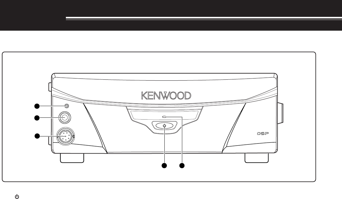
109
APPENDIX
TS-B2000 FRONT PANEL
PHONES
MIC
RESET
H
F
/
V
H
F
/
U
H
F
/
A
L
L
M
O
D
E
M
U
L
T
I
B
A
N
D
E
R
T
S
-
B
2
0
0
0
DIGITAL
SIGNAL
PROCESSOR
2
5
3
4
1
q[ ] (POWER) switch
Press and hold briefly to switch the transceiver power
ON. Press again to switch the power OFF.
wPower indicator
While the transceiver is turned ON, it lights red.
eMIC connector
Connect a compatible microphone to this connector,
then securely screw down the connector locking ring
{page 3}.
rPHONES jack
Connect a set of headphones to this jack. Inserting a
plug into the jack automatically mutes the audio from
the speaker {page 3}.
tRESET button
Push this switch to reset the microprocessor in the
transceiver. This sets all the contents of the memory
function to the factory default values.

110
21 APPENDIX
BUILT-IN TNC COMMAND LIST
All descriptions in this section are for the users convenience only. KENWOOD will not support or warrantee this
documentation in any way. The built-in TNC does not support the digipeater functions due to the RAM capacity.
dnammoC emaN trohS tluafeD retemaraP noitpircseD
FLOTUAUANOFFO/NO retfaretupmocehtot)FL(deefenilasdnes,NOnehW .)RC(nruteregairrachcae
NELWAWA88/7.tsohstidnaCNTneewtebstibfohtgnelehtsteS
NOCAEBB0YREVE
/YREVE nRETFA ~0=n( )052
ehtfoslavretnitatekcapnocaebasdnes,YREVEottesfI nocaebasdnes,RETFAottesfI.)n(doirepdeificeps fotinuehT.)n(doirepdeificepsehtretfaecnoylnotekcap .sdnoces01sin
TXETBTB— 951~0 sretcarahc nocaebafonoitropatadehtfotnetnocehtseificepS .tekcap
ARBILACLAC—— otQretnE.)oitar05/05(evawerauqskram/ecapsasdneS .edomdnammoCehterotserdnaedometarbilaCtixe
KCEHCHC03052~0 fonoitucexelitnutuo-pordlangismorflavretniehtseificepS .sdnoces01siretemarapehtfotinuehT.noitcennocsid
TCENNOCC—
AIV(1llaC ,3llac,2llac )9llac...
ehtfongisllacehtsi1llaC.tseuqertcennocasdneS fosngisllacera9llacot2llaC.otdetcennocebotnoitats .hguorhtdetaepigidebotsnoitats
ESREVNOCKroVNOC—— sserP.edomesrevnoCretneotCNTehtsesuaC ]C[+]lrtC[ .edomdnammoCehterotserot
EMITCAPCPCFFOFFO/NO tatekcapasdnes,edomesrevnoCnidnaNOnehW .EMITCAPybdenimreteddoirepehtfoslavretni
RCRCNOFFO/NO otstekcapllaot)RC(nruteregairracasdneppa,NOnehW .tneseb
ENNOCSIDD—— .tseuqertcennocsidasdneS
YALPSIDPSID——
ehtllafosutatstnerrucehtyalpsidotCNTehtsesuaC ,H,C,AreifitnedissalcayficepsoslanacuoY.sdnammoc derisedehtylnofosutatsehtyalpsidotTro,M,L,I dnammocehtneewtebecapsaretnE.ssalcdnammoc .HYALPSID.xe;reifitnedissalcadnaeman
sretemaraptropC232-SR:)CNYSA(A sretcarahcCNTlaicepS:)RAHC(C sretemarapretnuoC:)HTLAEH(H sretemarapDI:)DI(I sutatsknilCNT-ot-CNT:)KNIL(L sretemaraprotinoM:)ROTINOM(M sretemarapgnimiT:)GNIMIT(T
TIAWDWD03052~0 litnunoitcetedreirraconmorflavretniehtseificepS siretemarapehtfotinuehT.noissimsnartfonoitucexe .sdnocesillim01
OHCEENOFFO/NO otsretcarahcdeviecerohceotCNTehtsesuac,NOnehW .retupmoceht
RNRMRIFRIFFFOFFO/NO
tonsitifiuoyot)tekcap(ecitonasdnesnoitatsrehtoehT ecitonahcusgniviecer,NOnehW.atadeviecerotydaer aseviecertilitnunoissimsnartdnepsusotCNTehtsesuac .eciton”ydaer“

111
21 APPENDIX
dnammoC emaN trohS tluafeD retemaraP noitpircseD
WOLFFNOFFO/NO potsotretupmocehtsesuacyrtneyekgnitrats,NOnehW .stekcapdeviecergniyalpsid
KCARFRF3 052~0 foyrterlitnunoissimsnartenomorflavretniehtseificepS .dnoces1siretemarapehtfotinuehT.noissimsnart
DUABHBH00210069/0021 neewtebetarrefsnartehtsaspb0069ro0021stceleS .snoitatstekcap
SSIKSSIKFFOFFO/NO
.FFOreviecsnartehthctiwsneht,NOretemarapehtteS nehW.edomSSIKretneotniagaNOreviecsnartehtnruT ”NOC“dna”ATS“eht,edomSSIKsretnereviecsnarteht ,edomSSIKtixeoT.semitwefaylevitanretlaknilbsDEL ehtnrutroCNTehtot0CFF0Catadyranibehtdnes reviecsnartehtnrutuoyemittxenehT.FFOreviecsnart .yllacitamotuaFFOretemarapehtstesCNTeht,NO
MOCMMOCMFFOFFO/NO .stekcaplortnocrotinomoslaotCNTehtsesuac,NOnehW .stekcapnoitamrofniylnorotinomottisesuac,FFOnehW
NOCMCMFFOFFO/NO elihwsnoitatsrehtorotinomotCNTehtsesuac,NOnehW .noitatstegratehthtiwnoitcennocni
ROTINOMMNOFFO/NO.stekcaprotinomotCNTehtsesuac,NOnehW
TPRMRMNOFFO/NO tsiltaepigideritneehtyalpsidotCNTehtsesuac,NOnehW .stekcapderotinomrof
LLACYMYMLLACON 6sretcarahc DISS+ .ngisllacruoyseificepS
NELCAPP821552~0 afonoitropatadehtfohtgnelmumixamehtseificepS .tekcap
EMITCAPTCAP01RETFA
/YREVE nRETFA ~0=n( )052
deificepsehtfoslavretnitatekcapasdnes,YREVEottesfI retfaecnoylnotekcapasdnes,RETFAottesfI.)n(doirep .sdnocesillim001sinfotinuehT.)n(doirepdeificepseht
TSISREPEP821552~0 ehtrofytilibaborpetaluclacotretemarapaseificepS .dohtemEMITTOLS/TSISREP
TSISREPPPPNOFFO/NO dohtemEMITTOLS/TSISREPehtesuotCNTehtsesuaC .FFOnehwdohtemTIAWDehtro,NOnehw
TESERTESER—— .sdnammocehtllarofsutatstluafedehtserotseR
EMITPSERSER5 052~0 .yalednoissimsnarttekcaptnemgdelwonkcaehtseificepS .sdnocesillim001siretemarapehtfotinuehT
TRATSER
TRATSER
—— nehtFFOdehctiwssitifisanoitcnufotCNTehtsesuaC .NO
YRTERER0151~0 erastekcapfI.seirternoissimsnartforebmunehtseificepS tcennoca,noitcennocnielihwdetpeccayltcerrocton .seirterforebmundeificepsehtretfaniagatnessitseuqer
CAPDNESESD0$F7$~0.tnesebottekcapasecrofhcihwretcarahcaseificepS

112
21 APPENDIX
Note:
◆
If you are using a PC with a communication program to control the built-in TNC, prepare the RS-232C cable (straight) to connect with the COM
terminal of the transceiver. Then, access Menu No. 56 and select the same communication speed and communications parameters. Other
than 4800 bps, the parameters must be set to 8-bit, 1-stop bit, and non-parity. 4800 bps is also used for the Quick Data Transfer function
{page 80} and the communication parameters are fixed as 8-bit, 2-stop bit, and non-parity.
◆
To use the above commands, you must operate the transceiver in Packet communication mode. The default operation mode is PC Control
Command mode {page 113}. To switch to Packet communication mode, either set Menu No. 55 to “ON” {pages 25, 49} or key in “TC 0”
{page 138}.
dnammoC emaN trohS tluafeD retemaraP noitpircseD
EMITTOLSLS3 052~0 slavretninoitarenegrebmunmodnarfodoirepehtseificepS ehtfotinuehT.dohtemEMITTOLS/TSISREPehtrof .sdnocesillim01siretemarap
ECARTCARTFFOFFO/NO stekcapdeviecerllayalpsidotCNTehtsesuac,NOnehW .yteritneriehtni
SEIRTIRT0 51~0 nidemmargorpseirternoissimsnartforebmunehtseificepS .retnuocyrtereht
YALEDXTXT05021~0 fotratsehtdnaNOTTPneewtebyaledemitehtseificepS .sdnocesillim01siretemarapehtfotinuehT.noissimsnart
OTORPNU
U
QC AIV(1llaC ,3llac,2llac )9llac...
.edomlocotorpnUnitekcapadnesotsngisllacseificepS era9llacot2llaC.noitanitsedehtfongisllacehtsi1llaC .hguorhtdetaepigidebotsnoitatsfosngisllac
WOLFXXNOFFO/NO ,NOnehwlortnocwolferawtfosmrofrepotCNTehtsesuaC .FFOnehwlortnocwolferawdrahro
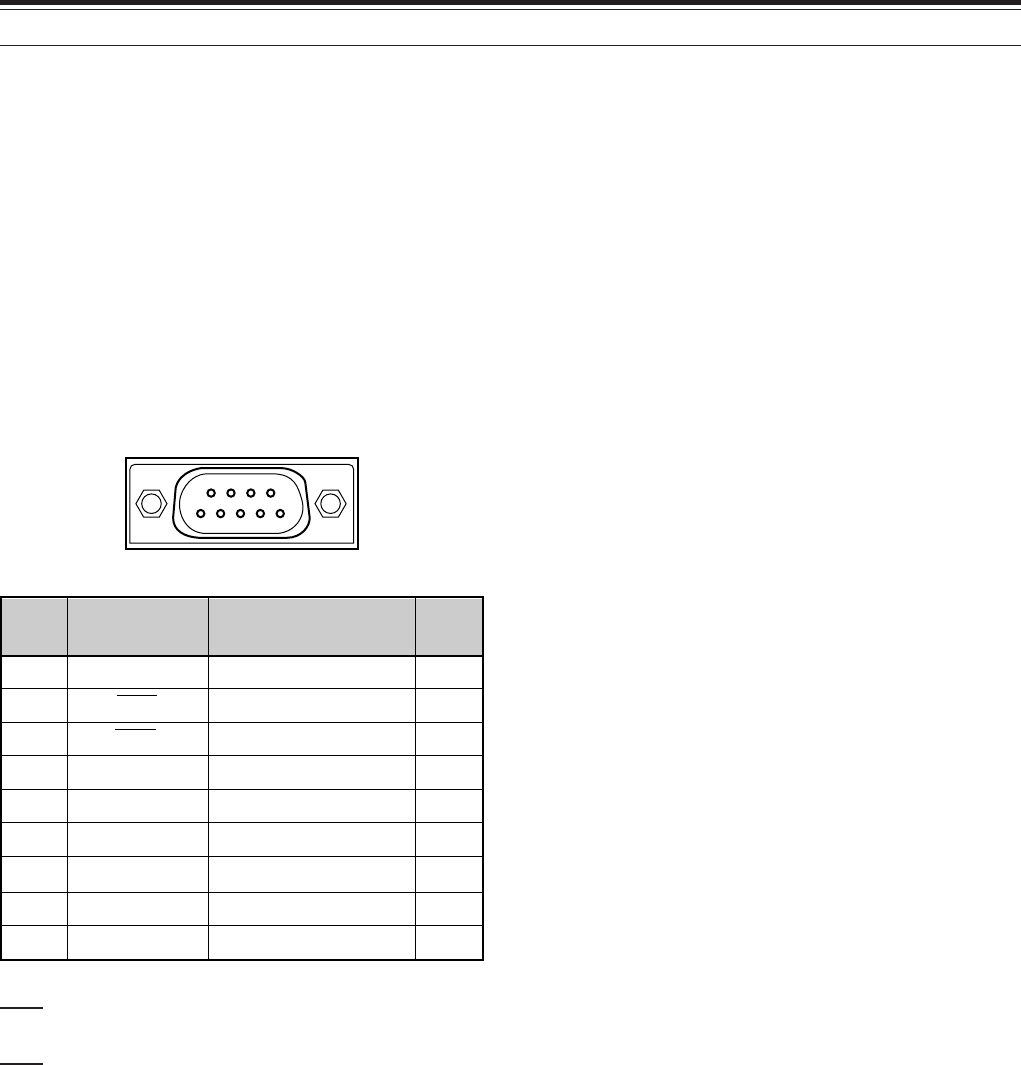
113
21 APPENDIX
COM CONNECTOR
All descriptions in the PC CONTROL COMMAND
TABLE are for the users convenience only.
KENWOOD will not support or warrantee this
documentation in any way.
HARDWARE DESCRIPTION
This transceiver uses a full-duplex, asynchronous,
serial interface for communicating through the male
9-PIN RS-232C COM connector. Each data is
constructed with 1 start bit, 8 data bits, and 1 stop bit
(4800 bps must be configured as 2 stop bits). No
parity is used. The pinout and the pin functions of the
COM connector are shown below:
COM
12345
9876
Rear panel view
1
2
3
4
5
6
7
8
9
—
Transmit data
Receive data
—
Signal ground
—
Receive enable
Transmit enable
—
—
Output
Input
—
—
Input
Output
—
COM
Pin No. COM Pin Name
(Ref.: Computer) Function
(Ref.: Transceiver) I/O
NC
RXD
TXD
NC
GND
NC
RTS
CTS
NC
RXD: Transmit data is serial data transferred from
the transceiver to the computer.
TXD: Receive data is serial data transferred from
the computer to the transceiver.
GND: Signal ground pin
RTS: This signal is applied to the transceiver. It is
used to inhibit transmit data from the transceiver
when the computer is not ready to receive data.
Transmit data is inhibited when the level is low.
CTS: This signal is applied from the transceiver. It
is used to inhibit transmit data from the computer
when the transceiver is not ready to receive data.
Transmit data is stopped when the level is low.
CONTROL OPERATION
Most computers handle data in the form of “bits” and
“bytes”. A bit is the smallest piece of information that
a computer can handle. A byte is composed of eight
bits. This is the most convenient form for most
computer data. This data may be sent in the form of
either serial or parallel data strings. The parallel
method is faster but more complicated, while the
serial method is slower and requires less complicated
equipment. The serial form is, therefore, a less
expensive alternative.
Serial data transmission uses time-division methods
over a single line. Using a single line also offers the
advantage of reducing the number of errors due to
line noise.
Only 3 lines are required theoretically for control of
the transceiver via the computer:
• Transmit data
• Receive data
• Ground
From a practical standpoint, it is also necessary to
incorporate some means of controlling when this data
transfer will occur. The computer and transceiver
cannot be allowed to send data at the same time!
The required control is achieved by using the RTS
and CTS lines.
For example, the transceiver is placed into the
transmit mode whenever the character string “TX;” is
sent from the computer. The character string “TX;” is
called a computer control command. It tells the
transceiver what to do. There are numerous
commands available for control of the transceiver.
These commands may be incorporated into a
computer program written in any high level language.
Programming methods vary from computer to
computer; therefore, refer to the instruction manuals
provided with the terminal program and computer.
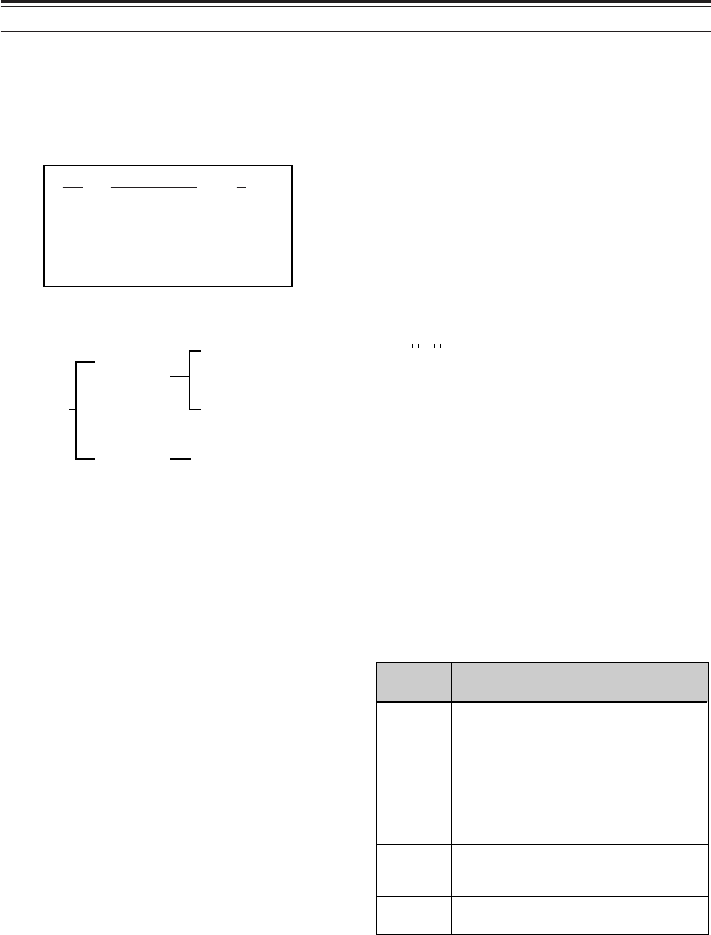
114
21 APPENDIX
■Parameters
Parameters are used to specify information
necessary to implement the desired command.
The parameters to be used for each command are
predetermined. The number of digits assigned to
each parameter is also predetermined. Refer to
the Computer Control Commands and the PC
Control Command Tables {page 115} to configure
the appropriate parameters.
When configuring parameters, be careful not to
make the following mistakes.
(correct parameter: “IS+1000”)
IS1000; Not enough parameters specified
(No direction given for the IF shift)
IS+100; Not enough digits
(Only three frequency digits given)
IS +1000; Unnecessary characters between
parameters
IS+10000; Too many digits
(Five frequency digits given)
Note: If a particular parameter is not applicable to this
transceiver, the parameter digits should be filled using any
character except the ASCII control codes (00 to 1Fh) and the
terminator (;).
■Terminator
To signal the end of a command, it is necessary to
use a semicolon (;). The digit where this special
character must appear differs depending on the
command used.
■Error Messages
In addition to the Answer command, the
transceiver can send the following error
messages.
Error
Message Reason for Error
• Command syntax was incorrect.
• Command was not executed due to
the current status of the transceiver
(even though the command syntax
was correct).
A communication error occurred such
as an overrun or framing error during a
serial data transmission.
Receive data was sent but processing
was not completed.
?;
E;
O;
Note: Occasionally this message may not
appear due to microprocessor transients in the
transceiver.
COMPUTER CONTROL COMMANDS
A computer control command is composed of an
alphabetical command, various parameters, and the
terminator that signals the end of the control
command.
EXAMPLE: Command to set VFO A to 7 MHz
Alphabetical command
;
Terminator
00007000000FA
Parameters
Commands can be classified as shown below:
Input
command
(Input to the
transceiver)
Output
command
(From the
transceiver)
Set command
(Sets a
particular condition)
Read command
(Reads an answer)
Answer command
(Transmits a condition)
Computer
control
commands
For example, note the following in the case of the FA
command (Frequency of VFO A):
• To set the frequency to 7 MHz, the following
command is sent from the computer to the
transceiver:
“FA00007000000;” (Set command)
• To read the frequency of VFO A, the following
command is sent from the computer to the
transceiver:
“FA;” (Read command)
• When the Read command above has been sent,
the following command is returned to the
computer:
“FA00007000000;” (Answer command)
Note:
◆
Do not use the control characters 00 to 1Fh since they are either
ignored or cause a “?” answer.
◆
Program execution may be delayed while turning the Tuning
control rapidly.
◆
Receive data is not processed if the frequency is entered from
the keypad.
■Alphabetical Commands
A command consists of 2 alphabetical characters.
You may use either lower or upper case
characters. The commands available for this
transceiver are listed in the PC Control Command
Tables {page 115}.

115
21 APPENDIX
CA
.sutatsrenutannetnalanretniehtsdaerrosteS :sretemaraP1P URHTTA-XR:0 NITA-XR:1
2P URHTTA-XT:0 NITA-XT:1
3P )rewsnA(deppotssigninuT/)teS(gninutpotS:0 )rewsnA(evitcasigninuT/)teS(gninuTtratS:1 detelpmocebtonnacgninuT:2
teS
123456789 01
AC 1P2P3P;
daeR
123456789 01
AC ;
rewsnA
123456789 01
AC 1P2P3P;
GA
.niagFAehtsdaerrosteS :sretemaraP1P reviecsnartniaM:0 reviecer-buS:1
2P ).xam(552~).nim(000
teS
123456789 01
AG 1P2P2P2P;
daeR
123456789 01
AG 1P;
rewsnA
123456789 01
AG 1P2P2P2P;
IA
.FFO/NOnoitcnuf)IA(noitamrofnIotuAehtsdaerrosteS :sretemaraP1P FFOIA:0 NOsitamrofIAdloylnO:1 NOsitamrofIAdednetxeylnO:2 NOerastamrofhtoB:3
reviecsnarteht,detcelessitamrofIAdednetxeehtnehW .sretemarapehtsdnesyllacitamotua
teS
123456789 01
AI 1P;
daeR
123456789 01
AI ;
rewsnA
123456789 01
AI 1P;
LA
.leveIhctoNotuAehtsdaerrosteS :sretemaraP1P 400~000
teS
123456789 01
AL 1P1P1P;
daeR
123456789 01
AL ;
rewsnA
123456789 01
AL 1P1P1P;
MA
.FFO/NOedoMotuAehtsdaerrosteS :sretemaraP1P FFOsinoitcnufedoMotuA:0 NOsinoitcnufedoMotuA:1
teS
123456789 01
AM 1P;
daeR
123456789 01
AM ;
rewsnA
123456789 01
AM 1P;
PC CONTROL COMMAND TABLES

116
21 APPENDIX
NA
.2TNA/1TNArotcennocannetnaehtstceleS :sretemaraP1P noitcelesannetnatnerrucehtsdaeR:0 1TNAstceleS:1 2TNAstceleS:2
teS
123456789 01
AN 1P;
daeR
123456789 01
AN ;
rewsnA
123456789 01
AN 1P;
RA
.FFO/NOnoitcnufCSAehtsdaerrosteS .noitcnufCSAehtfosutatsehtstropeR :sretemaraP1P reviecsnartniaM:0 reviecer-buS:1
2P FFOCSA:0 NOCSA:1
3P elbissopsitcatnocxelpmiS:0 elbissoptonsitcatnocxelpmiS:1 CSAnehW.dnab”LRTC“otylnodilavsiretemarap2P .nwonknusiesnopsereht,FFOsinoitcnuf
teS
123456789 01
AR 1P2P3P;
daeR
123456789 01
AR 1P;
rewsnA
123456789 01
AR 1P2P3P;
SA
.sretemarapnoitcnufedoMotuAehtsdaerrosteS :sretemaraP1P dnabzHM05~FH:0 dnabzHM441:1 dnabzHM044/034:2 dnabzHG2.1:3
2P 99~00 )stniop82(dnabzHM05~FH:82~00 stniop8(dnabzHG2.1,zHM044/034,zHM441:80~00 )dnabhcaerof
3P )tigid-11(zHniycneuqerF
4P devreseR:0 BSL:1 BSU:2 WC:3 MF:4 MA:5 KSF:6 R-WC:7 devreseR:8 R-KSF:9
teS
123456789 01
AS 1P2P2P3P3P3P3P3P
11213141516171819102
3P3P3P3P3P3P4P;
daeR
123456789 01
AS 1P2P2P;
rewsnA
123456789 01
AS 1P2P2P3P3P3P3P3P
11213141516171819102
3P3P3P3P3P3P4P;
CB
.sutatsnoitcnufrellecnaCtaeBehtsdaerrosteS :sretemaraP1P FFOrellecnaCtaeB:0 NOrellecnaCtaeBotuA:1 NOrellecnaCtaeBlaunaM:2
teS
123456789 01
BC 1P;
daeR
123456789 01
BC ;
rewsnA
123456789 01
BC 1P;
DB
.dnabycneuqerfehtnwodsevoM :sretemaraP enoN
teS
123456789 01
BD ;
daeR
123456789 01
rewsnA
123456789 01

117
21 APPENDIX
PB
.sgnittesycneuqerfrellecnaCtaeBlaunaMehtsdaerrosteS :sretemaraP1P 360~000
teS
123456789 01
BP 1P1P1P;
daeR
123456789 01
BP ;
rewsnA
123456789 01
BP 1P1P1P;
UB
.dnabycneuqerfehtpusevoM :sretemaraP enoN
teS
123456789 01
BU ;
daeR
123456789 01
rewsnA
123456789 01
YB
.sutatslangisysubehtsdaeR :sretemaraP1P reviecsnartniaM ysubtoN:0 ysuB:1
2P reviecer-buS ysuBtoN:0 ysuB:1
1Pehtylno,NOsinoitcnufdnammoCykSehtnehW .desusiretemarap
teS
123456789 01
daeR
123456789 01
BY ;
rewsnA
123456789 01
BY 1P2P;
AC
.sutatsnoitcnufENUTOTUAWCehtsdaerdnasteS :sretemaraP1P evitcatoN/noitcnufGNINUTOTUAWCslecnaC:0 evitcA/noitcnufGNINUTOTUAWCsetavitcA:1
teS
123456789 01
CA 1P;
daeR
123456789 01
CA ;
rewsnA
123456789 01
CA 1P;
GC
.sutatsNIAGREIRRACehtsdaerdnasteS :sretemaraP1P ).xam(001~).nim(000
teS
123456789 01
CG 1P1P1P;
daeR
123456789 01
CG ;
rewsnA
123456789 01
CG 1P1P1P;

118
21 APPENDIX
HC
.lennahcLLACehtotycneuqerftnerrucehtsteS :sretemaraP1P pupets1lortnocHC/ITLUMehtevoM:0 nwodpets1lortnocHC/ITLUMehtevoM:1
teS
123456789 01
CH 1P;
daeR
123456789 01
rewsnA
123456789 01
IC
.lennahcLLACehtotycneuqerftnerrucehtsteS :sretemaraP enoN
ehtstesti,edomllaceryromeMroedomOFVnielihW .lennahcLLACehtotycneuqerf
teS
123456789 01
CI ;
daeR
123456789 01
rewsnA
123456789 01
MC
/NOnoitcnufENUTRETSULCTEKCAPehtsdaerrosteS .FFO :sretemaraP1P FFOnoitcnufenuTretsulCtekcaP:0 NOnoitcnufenuTretsulCtekcaP:1
teS
123456789 01
CM 1P;
daeR
123456789 01
CM ;
rewsnA
123456789 01
CM 1P;
NC
.noitcnufSSCTCehtsdaerdnasteS :sretemaraP1P 83~10
.srebmunenotSSCTCehtrof53egapotrefeR
teS
123456789 01
CN 1P1P;
daeR
123456789 01
CN ;
rewsnA
123456789 01
CN 1P1P;
TC
.sutatsnoitcnufSSCTCehtsdaerdnasteS :sretemaraP1P FFOnoitcnufSSCTC:0 NOnoitcnufSSCTC:1
teS
123456789 01
CT 1P;
daeR
123456789 01
CT ;
rewsnA
123456789 01
CT 1P;

119
21 APPENDIX
CD
.sutatsdnabXTehtsdaerdnasteS :sretemaraP1P reviecsnartniamehtotdnabXTsteS:0 NOreviecer-busehtotdnabXTsteS:1
2P reviecsnartniamehtotdnabLORTNOCsteS:0 reviecer-busehtotdnabLORTNOCsteS:1
tessiretemarapemaseht,segnahcretemarap1PehtnehW .2Pot
teS
123456789 01
DC 1P2P;
daeR
123456789 01
DC ;
rewsnA
123456789 01
DC 1P2P;
ND
.yekNWDenohporcimehtsetalumE :sretemaraP1P 99~00
sadeterpretnisidnammoceht,deificepssiretmarap1PonfI .nwodpets1 dnammoceht,edomyromeMkciuQdnaedomyromeMnI nwodlennahcyromeMasadetaertsiretemarapatuohtiw ycneuqerfehtsadetaertsiti,sretemaraphtiW.dnammoc .dnammocnwod
teS
123456789 01
DN 1P1P;
daeR
123456789 01
rewsnA
123456789 01
QD
.sutatsnoitcnufSCDehtsdaerdnasteS :sretemaraP1P FFOnoitcnufSCD:0 NOnoitcnufSCD:1
teS
123456789 01
DQ 1P;
daeR
123456789 01
DQ ;
rewsnA
123456789 01
DQ 1P;
XE
.uneMnoisnetxEehtsdaerrosteS :sretemaraP1P )ts1(.oNuneM:999~000
2P )dn2(.oNuneM:99~00
3P )dr3(.oNuneM:9~0
4P )ht4(.oNuneM:9~0
5P sretcarahcfognirtsA )htgnelelbairaV(
.”00“tes,elbaliavatonerasunemdr3dnadn2ehtfI .ylnotigid1yficepS :ssenthgirbyalpsiD .)FFOremmiD(;00000000XE .)2levelremmiD(;30000000XE tigid-2evahC26dna95,E~A15,33,13,B92uneM .sretemarap .)tigid-3(999~000:)5P(C16uneM .sretcarahc8fomumixamA:)5P(B~A26uneM .rebmunlennahcyromeMFMTDrof9~0:)3P(A54uneM )edoC(1,)FMTD(0:)4P(A54uneM retcarahctsrifehtfI.stigid61fomumixamA:)5P(A54uneM B26dnaA26.deraelceblliwemaneht,retcarahcecapsasi .”LLACON“emoceb XEehtgnisu,NO55.oNuneMnrutnacuoyhguohtlA .FFOtinrutotdnammoc;1CTehtesutsumuoy,dnammoc
teS
123456789 01
EX 1P1P1P2P2P3P4P5P
11213141516171819102
5P5P5P5P5P5P5P5P5P5P
12223242526272829203
5P5P5P5P5P;
daeR
123456789 01
EX 1P1P1P2P2P3P4P;
rewsnA
123456789 01
EX 1P1P1P2P2P3P4P5P
11213141516171819102
5P5P5P5P5P5P5P5P5P5P
12223242526272829203
5P5P5P5P5P;

120
21 APPENDIX
uneM .oN noitcnuF 5PretemarapdnammocXE
0 1 2 3 4 5 6 7 8 9 revO
00ssenthgirbyalpsiDFFO 1234
10noitanimulliyeKFFONO
20noituloverrepegnahclortnocgninuT0050001
30ehthtiwgninuT HC/ITLUM lortnocFFONO
40 seicneuqerfOFVffosdnuoR ehtgnisuybdegnahc HC/ITLUM
lortnoc FFONO
50 ehtrofezispetsycneuqerfzHk9 HC/ITLUM noedomMAnilortnoc dnabtsacdaorbMAeht FFONO
A60noitarepotilpsOFV-yromeMFFONO
B60 yromem)FFO(dexifro)NO(elbanuT seicneuqerflennahc FFONO
70dewolsyllaitrapnacsmargorPFFONO
80 ehtrofegnarycneuqerfnwodwolS nacsmargorP 001002003004005
90dlohnacsmargorPFFONO
01dohtememusernacSOTOC
11egnarnacslausiV131619181
21leveltuptuopeeBFFO 123456789
31emulovenotedisXTFFO 123456789
41emulovkcabyalpA3-URDFFO 123456789
51emulovkcabyalp3-SVFFO 123456789
61 rofnoitarugifnoctuptuooiduA enohpdaehro2PS.TXE 012
71 2PS.TXEdna1PS.TXEehtsesreveR )slennahcR/Lkcajenohpdaeheht( stuptuooidua FFONO
81 TNAXRFHehtmorftupninaelbanE rotcennoc FFONO
A91hcleuqsretem-SFFONO
B91hcleuqsretem-SrofemitgnaHFFO521052005
02rezilauqeXRPSDFFO
HTSOOB SSAPF BTSOOB -VNOC NE RESU
12rezilauqeXTPSDFFO
HTSOOB SSAPF BTSOOB -VNOC NE RESU
22 roBSSrofhtdiwdnabretlifXTPSDMA 0.22.24.26.28.20.3
32gninutrewoptimsnarteniFFFONO
42remiTtuo-emiTFFO35010203
52yalpsidycneuqerfretrevsnarTFFONO
62 ehtsetelpmocTAnehwdlohXT gninut FFONO
72gniviecerelihwTAenil-nIFFON1O
A82 FHrofyaledlortnocreifilpmaraeniL dnab FFO12
B82 rofyaledlortnocreifilpmaraeniL dnabzHM05 FFO12
C82 rofyaledlortnocreifilpmaraeniL dnabzHM441 FFO12
D82 rofyaledlortnocreifilpmaraeniL dnabzHM044/034 FFO12
E82 rofyaledlortnocreifilpmaraeniL dnabzHG2.1 FFO12
A92kcabyalpehttaepeRFFONO
B92 ehtgnitaeperrofemitlavretnI kcabyalp 0123456789 06~ )1fospetsni(
03kcabyalprevoytiroirpgniyeKFFONO

121
21 APPENDIX
uneM .oN noitcnuF 5PretemarapdnammocXE
0 1 2 3 4 5 6 7 8 9 revO
13ycneuqerfenotedisXT/hctipXRWC004054005055006056007057008058 0001~ )05fospetsni(
23emitesirWC 1246
33oitarthgiewhsad,todgniyekWCOTUA5.26.27.28.29.20.31.32.33.3 0.4~ )1.0fospetsni(
43oitarthgiewotuagniyekWCesreveRFFONO
53edomyekguBFFONO
63edomBSSniXTWCotuAFFONO
73 gnignahcrofnoitcerrocycneuqerF WCotBSS FFONO
83tfihsKSF071002524058
93ytiralopgniyekKSF -RON LAM -EVNI SR
04ycneuqerfenotKSF57215212
14MFrofniagciMWOLDIMHGIH
24MFrofedomenot-buS
TSRUB
TNOC
34tesfforetaeperotuAFFONO
44enotzH0571:dlohXTFFONO
A54tcelesyromemrebmunFMTD.stnemmocretemarapehteeS
B54rebmunFMTDderotsrofdeepsXTWOLSTSAF
C54 FMTDderotsrofnoitarudesuaP rebmun 001052
D54lortnocetomerciMelbanEFFONO
64CNTlanretnI:dnabBUS/NIAMNIAMBUS
74CNTlanretnI:deepsrefsnartataD00210069
84dnabgnisnesDCD CNT DNAB -NIAM BUS&
A94edomenuTretsulCtekcaPOTUA -NAM LAU
B94enotnoitamrifnocXRretsulCtekcaPFFO -ROM ES ECIOV
A05htdiwdnabretliftekcaPFFONO
B05tekcaProfleveltupniFA01
C05 rofleveltuptuoFAdnabNIAM noitarepotekcap 01
D05 tekcaprofleveltuptuoFAdnabBUS noitarepo 01
E05CNTlanretxE:dnabBUS/NIAMNIAMBUS
F05CNTlanretxE:deepsrefsnartataD00210069
A15yekFPlenaptnorF )tigid-2(99~00 ,INOMPSD:66,INOMXR:56,2ECIOV:46,1ECIOV:36,.oNuneM:26~0 ,M/OFV:27,B/A:17,TES-FT:07,TILPS:96,NI.MOMEMKCIUQ:86,RMOMEMKCIUQ:76 ,3HC:08,2HC:97,1HC:87,ENUTWC:77,NI.M:67,OFV>M:57,NACS:47,B=A:37 ,.C.B:98,.R.N:88,BN:78,2/1TNA:68,zHM1:58,LRTC:48,LLAC:38,RLC:28,ENIF:18 noitcnufoN:99,.N.A:09
.)edoctekramehtnognidneped(elbaliavaebtonyamsrebmununemllA
B15yek1FPenohporciM
C15yek2FPenohporciM
D15yek3FPenohporciM
E15yek4FPenohporciM
25 /retsamnirefsnartycneuqerftilpS noitarepoevals FFONO
35 tilpSderrefsnartehtetirwottimreP .sOFVtegratehtotseicneuqerf FFONO
45tibihniXTFFONO
55edomnoitacinummoctekcaPFFONO

122
21 APPENDIX
uneM .oN noitcnuF 5PretemarapdnammocXE
0 1 2 3 4 5 6 7 8 9 revO
65deepsnoitacinummoctropMOC00840069
75noitcnuf)ffOrewoPotuA(OPAFFO06
85edomnoitarepoysaenitnof0002-CR -TNOF 1-TNOF 2
95 -tod)X(0002-ST/lenap0002-CR tsartnocyalpsidxirtam 12
060002-CRrofedomyalpsiD -AGEN EVIT -ISOP EVIT
A16tcelesedomretaepeRFFO
-KCOL DE SSORC
B16dlohXTretaepeRFFONO
C16edocDIlortnocetomeR)rebmuntigid-3(999~000
D16 lanretxenilangistnemegdelwonkcA edomlortnocetomer FFONO
E16lortnocetomerlanretxEFFONO
A26 ykSrofngisllacrednammoC +IIdnammoC .38egapeeS.sretcarahc9fomumixamA
B26 ykSrofngisllacretropsnarT +IIdnammoC .38egapeeS.sretcarahc9fomumixamA
C26ycneuqerfenot+IIdnammoCykS.rebmunenotehtrof53egapeeS
D26 noitacinummoc+IIdnammoCykS deeps 00210069
E26edom+IIdnammoCykSFFO -ILC TNE -MOC DNAM -ROP-T RET

123
21 APPENDIX
AF
.ycneuqerfAOFVehtstesdnasdaeR :sretemaraP1P .)tigid-11(zHniycneuqerfehtyficepS stigidknalbehT.zHM591.41rof00059141000,elpmaxeroF .0ebtsum
teS
123456789 01
FA 1P1P1P1P1P1P1P1P
11213141516171819102
1P1P1P;
daeR
123456789 01
FA ;
rewsnA
123456789 01
FA 1P1P1P1P1P1P1P1P
11213141516171819102
1P1P1P;
BF
.ycneuqerfBOFVehtstesdnasdaeR :sretemaraP1P .)tigid-11(zHniycneuqerfehtyficepS stigidknalbehT.zHM591.41rof00059141000,elpmaxeroF .0ebtsum
teS
123456789 01
FB 1P1P1P1P1P1P1P1P
11213141516171819102
1P1P1P;
daeR
123456789 01
FB ;
rewsnA
123456789 01
FB 1P1P1P1P1P1P1P1P
11213141516171819102
1P1P1P;
CF
.ycneuqerfOFVs’reviecer-busehtstesdnasdaeR :sretemaraP1P .)tigid-11(zHniycneuqerfehtyficepS knalbehT.zHM591.441rof00059144100,elpmaxeroF nidesusiezispetsycneuqerfdilavniehtfI.0ebtsumstigid ehtstesyllacitamotuareviecsnarteht,retemarap1Peht .ycneuqerftseraen
teS
123456789 01
FC 1P1P1P1P1P1P1P1P
11213141516171819102
1P1P1P;
daeR
123456789 01
FC ;
rewsnA
123456789 01
FC 1P1P1P1P1P1P1P1P
11213141516171819102
1P1P1P;
DF
.nrettaptodyalpsidretlifehtsdaeR :sretemaraP1P )tib-23(DFFFFFFF~00000000 .stod03sahyalpsidhtdiwretlifehT erastib2tsalehT.tfelehtnotodastneserperBSM .desunu .0otteserastibesehT
teS
123456789 01
daeR
123456789 01
FD ;
rewsnA
123456789 01
FD 1P1P1P1P1P1P1P1P
11213141516171819102
;

124
21 APPENDIX
RF
.MOC/LLACroHC.M,OFVreviecerehtsdaerrostceleS :sretemaraP1P AOFV:0 BOFV:1 HC.M:2 LLAC:3
.dnab)lortnoC(LRTCtnerrucehtotdeilppasidnammocehT
teS
123456789 01
FR 1P;
daeR
123456789 01
FR ;
rewsnA
123456789 01
FR 1P;
SF
.sutatsnoitcnufENIFehtsdaerrostceleS :sretemaraP1P FFOnoitcnufENIF:0 NOnoitcnufENIF:1
teS
123456789 01
FS 1P;
daeR
123456789 01
FS ;
rewsnA
123456789 01
FS 1P;
TF
.MOC/LLACroHC.M,OFVs’rettimsnartehtsdaerrostceleS :sretemaraP1P AOFV:0 BOFV:1 HC.M:2 LLAC:3
.dnabXTtnerrucehtotdeilppasidnammocehT
teS
123456789 01
FT 1P;
daeR
123456789 01
FT ;
rewsnA
123456789 01
FT 1P;
WF
.htdiwretlifeviecerPSDehtsdaerrostceleS :sretemaraP1P )zHni(9999~0000 0002,0001,006,005,004,003,002,051,001,08,05:WC 0051,0001,005,052:KSF ediW=1000,worraN=0000:MA/MF
LSehtesU.dnammocWFehtesutonnacuoy,edomBSSnI .daetsnidnammocHSro
teS
123456789 01
FW 1P1P1P1P;
daeR
123456789 01
FW ;
rewsnA
123456789 01
FW 1P1P1P1P;
TG
.sutatstnatsnocCGAehtsdaerrostceleS :sretemaraP1P FFO=000 ).xam(020~).nim(100
reviecsnartehT.edomMFnidesuebtonnacsdnammocTG nidesusidnammocTGehtnehwsecaps3htiwsdnopser .edomMF
teS
123456789 01
GT 1P1P1P;
daeR
123456789 01
GT ;
rewsnA
123456789 01
GT 1P1P1P;

125
21 APPENDIX
DI
.rebmunDIreviecsnartehtsdaeR :sretemaraP1P 0002-ST:910
123456789 01
daeR
123456789 01
ID;
rewsnA
123456789 01
ID 1P1P1P;
FI
.sutatsreviecsnartehtseveirteR :sretemaraP1P )tigid-11(.zHniycneuqerfehtyficepS .”0“ebtsumstigidknalbehT2P .ezispetsycneuqerF3P ycneuqerfTIX/TIR ±zHni99999
4P NOTIR:1,FFOTIR:0
5P NOTIX:1,FFOTIX:0 CMeeS.rebmunknablennahcehtyficepS:7P,6P .dnammoc 8P XT:1,XR:0
9P .sliatedrofsdnammocDMeeS.edomgnitarepO
01P .sdnammocTFdnaRFeeS11P .dnammocCSeeS.sutatsnacS21P .dnammocPSeeS.sutatsnoitarepotilpS31P SCD:3,SSCTC:2,ENOT:1,FFO:041P .dnammocNTeeS.ycneuqerfenoT51P .dnammocSOeeS.sutatstfihS
51Pdna2Peht,+IIdnammoCykSgnitarepoelihW htgnelretemarap2PehT.knalbemocebsretemarap 5semocebhtgnelretemarap3Pehtdnasetyb5otsegnahc .setyb
teS
123456789 01
daeR
123456789 01
IF;
rewsnA
123456789 01
IF 1P1P1P1P1P1P1P1P
11213141516171819102
1P1P1P2P2P2P2P3P3P3P
12223242526272829203
3P3P3P4P5P6P7P7P8P9P
13233343536373839304
01P11P21P31P41P41P51P;
SI
.sutatsnoitcnufTFIHSFIehtsdaerdnasteS :sretemaraP1P ecaps
2P edomWCni)05fospetsni(0001~0040
MAro,MF,KSF,BSSnielihwdesuebtonnacsdnammocSI .edom
teS
123456789 01
IS 1P2P2P2P2P;
daeR
123456789 01
IS;
rewsnA
123456789 01
IS 1P2P2P2P2P;
SK
.reyekcirtceleehtfodeepsgniyekehtsdaerdnasteS :sretemaraP1P ]MPWni[).xam(060~).nim(010
teS
123456789 01
KS 1P1P1P;
daeR
123456789 01
KS ;
rewsnA
123456789 01
KS 1P1P1P;

126
21 APPENDIX
YK
.edocesroMotnisretcarahcehtstrevnoC :sretemaraP1P elbaliavasireffubretcarahC:0 elbaliavatonsireffubretcarahC:1 ).dnammocteSrofdesusiecapsA.ylnodnammocrewsnA( 2P srebmundnasretcarahcretnE :erasretcarahcelbaliavA )ecaps(_ZYXWVUTSRQPONMLKJIHGFEDCBA 9876543210 ?=:/.–,+*)('"
.retemarap2Pehtrofdesusihtgneletyb-42dexifehT .sretcarahcdesunuehtrofdesuebtsumretcarahc)ecaps(_ .detrevnoctonebtonlliwsretcarahcecapsesehT
teS
123456789 01
KY 1P2P2P2P2P2P2P2P
11213141516171819102
2P2P2P2P2P2P2P2P2P2P
12223242526272829203
2P2P2P2P2P2P2P;
daeR
123456789 01
KY ;
rewsnA
123456789 01
KY 1P;
KL
.sutatsnoitcnufkcolyekehtsdaerdnasteS :sretemaraP1P )0002B-ST/0002-ST(FFOnoitcnufkcoL:0 )0002B-ST/0002-ST(NOnoitcnufKCOL.F:1 )0002B-ST/0002-ST(NOnoitcnufKCOL.A:2
2P )0002-CR(FFOnoitcnufKCOL:0 )0002-CR(NOnoitcnufKCOL:1
teS
123456789 01
LK 1P2P;
daeR
123456789 01
LK ;
rewsnA
123456789 01
LK 1P2P;
ML
gnidrocerreyekcirtcelerotinuA3-URDehtsdaerdnasteS .sutats :sretemaraP1P )ylnodnammocteS(gnidrocerpotS:0 evitcanisinoitcnufgnidroceR:0 1HCotgnidrocertratS:1 2HCotgnidrocertratS:2 3HCotgnidrocertratS:3
teS
123456789 01
LM 1P;
daeR
123456789 01
LM ;
rewsnA
123456789 01
LM 1P;
TL
.sutatsnoitcnufTLAehtsdaerdnasteS :sretemaraP1P FFOnoitcnufTLA:0 NOnoitcnufTLA:1
teS
123456789 01
LT 1P;
daeR
123456789 01
LT ;
rewsnA
123456789 01
LT 1P;
CM
.lennahcyromeMehtsdaerrosllaceR :sretemaraP1P rebmunknaboN:)ecaps(_ rebmunknabyromeM:2~0
2P rebmunlennahC:99~00
sadetaertera99ot00morfsrebmunlennahcyromeM 991ot001morfsrebmunlennahcyromeM.0knabyromeM srebmunlennahcyromeM.1knabyromeMsadetaertera .2knabyromeMsadetaertera992ot002morf
teS
123456789 01
MC 1P2P2P;
daeR
123456789 01
MC ;
rewsnA
123456789 01
MC 1P2P2P;

127
21 APPENDIX
DM
.sutatsedomgnitarepoehtsdaerrosllaceR :sretemaraP1P BSL:1 BSU:2 WC:3 MF:4 MA:5 KSF:6 R-RC:7 devreseR:8 R-KSF:9
teS
123456789 01
MD 1P;
daeR
123456789 01
MD ;
rewsnA
123456789 01
MD 1P;
FM
.BroAuneMsdaerrosteS :sretemaraP1P AuneM:0 BuneM:1
teS
123456789 01
MF 1P;
daeR
123456789 01
MF ;
rewsnA
123456789 01
MF 1P;
GM
.sutatsniagenohporciMehtsdaerrosteS :sretemaraP1P ).xam(001~).nim(000
teS
123456789 01
MG 1P1P1P;
daeR
123456789 01
MG ;
rewsnA
123456789 01
MG 1P1P1P;
LM
.levelnoitcnufROTINOMehtsdaerrosteS :sretemaraP1P FFOROTINOM:000 ).xam(900~).nim(100
teS
123456789 01
ML 1P1P1P;
daeR
123456789 01
ML ;
rewsnA
123456789 01
ML 1P1P1P;
OM
rednammoCykSniFFO/NOnoitcnufROTINOMehtsteS .edom :sretemaraP1P FFOROTINOM:0 NOROTINOM:1
teS
123456789 01
MO 1P;
daeR
123456789 01
rewsnA
123456789 01
MO 1P;

128
21 APPENDIX
RM
.atadlennahcyromeMehtsdaeR :sretemaraP1P ycneuqerfXT:1,ycneuqerfXR:0 3P,2P .dnammocCMeeS.rebmunlennahcdnaknaB
4P .)tigid-11(zHniycneuqerF
5P .dnammocDMeeS.edoM
6P .NOtuokcoL:1,FFOtuokcoL:0.sutatstuokcoL
7P .SCD:3,SSCTC:2,ENOT:1,FFO:0
8P .53egapeeS.rebmuNenoT
9P .dnammocNCeeS.rebmunenotSSCTC01P .dnammocCQeeS.edocSCD11P .sutatsESREVER21P .dnammocSOeeS.sutatsTFIHS31P .dnammocSOeeS.ycneuqerftesffO
41P .dnammocTSeeS.ezispetS51P .)9~0(rebmunpuorGyromeM
61P .sretcarahc8fomumixamA.emanyromeM
:992~092lennahcyromeM )ycneuqerfdne(1=1P,)ycneuqerftrats(0=1P
teS
123456789 01
daeR
123456789 01
MR 1P2P3P3P;
rewsnA
123456789 01
MR 1P2P3P3P4P4P4P4P
11213141516171819102
4P4P4P4P4P4P4P5P6P7P
12223242526272829203
8P8P9P9P01P01P01P11P21P31P
13233343536373839304
31P31P31P31P31P31P31P31P41P41P
14243444546474849405
51P61P61P61P61P61P61P61P61P;
UM
.atadpuorGyromeMehtsdaerrosteS :sretemaraP1P 0puorGyromeM
2P 1puorGyromeM
3P 2puorGyromeM
4P 3puorGyromeM
5P 4puorGyromeM
6P 5puorGyromeM
7P 6puorGyromeM
8P 7puorGyromeM
9P 8puorGyromeM
01P 9puorGyromeM
detceleS:1,detcelesnU:0
teS
123456789 01
MU 1P2P3P4P5P6P7P8P
11213141516171819102
9P01P;
daeR
123456789 01
MU ;
rewsnA
123456789 01
MU 1P2P3P4P5P6P7P8P
11213141516171819102
9P01P;

129
21 APPENDIX
WM
.lennahcyromeMehtotatadehterotS :sretemaraP1P ycneuqerfXT:1,ycneuqerfXR:0 3P,2P .dnammocCMeeS.rebmunlennahcdnaknaB
4P .)tigid-11(zHniycneuqerF
5P .dnammocDMeeS.edoM
6P NOtuokcoL:1,FFOtuokcoL:0.sutatstuokcoL
7P SCD:3,SSCTC:2,ENOT:1,FFO:0
8P .53egapeeS.rebmuNenoT
9P .dnammocNCeeS.rebmunenotSSCTC01P .dnammocCQeeS.edocSCD11P .sutatsESREVER21P .dnammocSOeeS.sutatsTFIHS31P .dnammocSOeeS.ycneuqerftesffO
41P .dnammocTSeeS.ezispetS51P .)9~0(rebmunpuorGyromeM
61P .sretcarahc8fomumixamA.emanyromeM
:992~092lennahcyromeM )ycneuqerfdne(1=1P,)ycneuqerftrats(0=1P
teS
123456789 01
MW 1P2P3P3P4P4P4P4P
11213141516171819102
4P4P4P4P4P4P4P5P6P7P
12223242526272829203
8P8P9P9P01P01P01P11P21P31P
13233343536373839304
31P31P31P31P31P31P31P31P41P41P
14243444546474849405
51P61P61P61P61P61P61P61P61P;
daeR
123456789 01
rewsnA
123456789 01
BN
.sutatsnoitcnuf)reknalBesioN(BNehtsdaerroteS :sretemaraP1P FFOBN:0 NOBN:1
teS
123456789 01
NB 1P;
daeR
123456789 01
NB ;
rewsnA
123456789 01
NB 1P;
LN
.level)reknalBesioN(BNehtsdaerroteS :sretemaraP1P ).xam(010~).nim(100
.100sadetaertsi000 .010sadetaertera999~010
teS
123456789 01
NL 1P1P1P;
daeR
123456789 01
NL ;
rewsnA
123456789 01
NL 1P1P1P;
RN
.sutatsnoitcnuf)noitcudeResioN(RNehtsdaerrosteS :sretemaraP1P FFORN:0 NO1RN:1 NO2RN:2
teS
123456789 01
NR 1P;
daeR
123456789 01
NR ;
rewsnA
123456789 01
NR 1P;

130
21 APPENDIX
TN
.sutatsnoitcnufhctoNotuAehtsdaerrosteS :sretemaraP1P FFOhctoNotuA:0 NOhctoNotuA:1
teS
123456789 01
NT 1P;
daeR
123456789 01
NT ;
rewsnA
123456789 01
NT 1P;
FO
.noitamrofniycneuqerftesffOehtsdaerrosteS :sretemaraP1P 00005fospetsni000059950~000000000 .)tigid-9(zHniycneuqerftesffO .0ebtsumstigiddesunU
teS
123456789 01
OF 1P1P1P1P1P1P1P1P
11213141516171819102
1P;
daeR
123456789 01
OF ;
rewsnA
123456789 01
OF 1P1P1P1P1P1P1P1P
11213141516171819102
1P;
IO
.atadlennahcyromeMehtsdaeR :sretemaraP1P )stigid11(zHniycneuqerfehtyficepS .”0“ebtsumstigidknalbehT2P ezispetsycneuqerF3P ycneuqerfTIX/TIR ±zHni99999
4P NOTIR:1,FFOTIR:0
5P NOTIX:1,FFOTIX:0 CMeeS.rebmunknablennahcehtyficepS:7P,6P .dnammoc 8P XT:1,XR:0
9P .sliatedrofsdnammocDMeeS.edomgnitarepO
01P .sdnammocTFdnaRFeeS11P .dnammocCSeeS.sutatsnacS21P .dnammocPSeeS.sutatsnoitarepotilpS31P SCD:3,SSCTC:2,ENOT:1,FFO:041P .dnammocNTeeS.ycneuqerfenoT51P .dnammocSOeeS.sutatstfihS
51Pdna2Peht,+IIdnammoCykSgnitarepoelihW htgnelretemarap2PehT.knalbemocebsretemarap 5semocebhtgnelretemarap3Pehtdnasetyb5otsegnahc .setyb
teS
123456789 01
daeR
123456789 01
OI ;
rewsnA
123456789 01
OI 1P1P1P1P1P1P1P1P
11213141516171819102
1P1P1P2P2P2P2P3P3P3P
12223242526272829203
3P3P3P4P5P6P7P7P8P9P
13233343536373839304
01P11P21P31P41P41P51P;

131
21 APPENDIX
SO
.sutatsnoitcnuftesffoehtsdaerrosteS :sretemaraP1P xelpmiS:0 +:1 –:2 )sepyt-EllA(=:3
.FFOebtsumnoitcnufTILPS.edomMFniylnodilaV
teS
123456789 01
OS 1P;
daeR
123456789 01
OS ;
rewsnA
123456789 01
OS 1P;
AP
.sutatsnoitcnufreifilpma-erpehtsdaerrosteS :sretemaraP1P )reviecsnartniam(FFOreifilpma-erP:0 )reviecsnartniam(NOreifilpma-erP:1 )ylnorewsnA(2P )reviecer-bus(NOreifilpma-erP:0 )reviecer-bus(FFOreifilpma-erP:1
reviecsnartniamehtrofdetcelessidnabycneuqerfemasfI roNOdenruterasreifilpma-erphtob,reviecer-busehtdna .emitemasehttaFFO
teS
123456789 01
PA 1P;
daeR
123456789 01
PA ;
rewsnA
123456789 01
PA 1P2P;
BP
.sutatskcabyalpreyekcirtceleroA3-URDehtsdaerrosteS :sretemaraP1P evitcanI:0 1HCkcabyalP:1 2HCkcabyalP:2 3HCkcabyalP:3
teS
123456789 01
PB 1P;
daeR
123456789 01
PB ;
rewsnA
123456789 01
PB 1P;
CP
.rewoptuptuoehtsdaerrosteS :sretemaraP1P )1fospetsni(001~500
mumixamdnamuminimehtrofsnoitacificepSehtotrefeR .edomdnadnabycneuqerfgnitarepohcaerofrewop
.desusilevelrewoptxeneht,ttaw1nahtsselsirewopehtfI 100=W5.0,300=W5.2:xe
teS
123456789 01
PC 1P1P1P;
daeR
123456789 01
PC ;
rewsnA
123456789 01
PC 1P1P1P;
IP
.lennahcyromeMelbamargorPehtniserotS :sretemaraP1P )rebmunlennahcMP(5~1
teS
123456789 01
PI 1P;
daeR
123456789 01
rewsnA
123456789 01

132
21 APPENDIX
KP
.atadretsulCtekcaPehtsdaeR :sretemaraP .dnammocIAehthtiwnitcnujnocnidesusidnammocsihT
1P )tigid-11(zHniycneuqerF
2P )tigid-21(ngisllaC
3P )tigid-02(stnemmoC
4P )tigid-5(emiT
teS
123456789 01
daeR
123456789 01
rewsnA
123456789 01
PK 1P1P1P1P1P1P1P1P
11213141516171819102
1P1P1P2P2P2P2P2P2P2P
12223242526272829203
2P2P2P2P2P3P3P3P3P3P
13233343536373839304
3P3P3P3P3P3P3P3P3P3P
14243444546474849405
3P3P3P3P3P4P4P4P4P4P
15253545556575859506
;
LP
.leveltuptuo/tupnirossecorPhceepSehtsdaerdnasteS :sretemaraP1P :leveltupnI ).xam(001~).nim(000
2P :leveltuptuO ).xam(001~).nim(000
teS
123456789 01
PL 1P1P1P2P2P2P;
daeR
123456789 01
PL ;
rewsnA
123456789 01
PL 1P1P1P2P2P2P;
MP
.)yromeMelbammargorP(MPehtsllaceR :sretemaraP1P FFOMP:0 )rebmunlennahcMP(5~1
teS
123456789 01
PM 1P;
daeR
123456789 01
PM ;
rewsnA
123456789 01
PM 1P;
RP
.FFO/NOnoitcnufrossecorPhceepSehtsdaerrosteS :sretemaraP1P FFOrossecorPhceepS:0 NOrossecorPhceepS:1
teS
123456789 01
PR 1P;
daeR
123456789 01
PR ;
rewsnA
123456789 01
PR 1P;

133
21 APPENDIX
SP
.sutatsFFO/NOrewoPehtsdaerrosteS :sretemaraP1P NOrewoP:0 FFOrewoP:1
teS
123456789 01
PS 1P;
daeR
123456789 01
PS ;
rewsnA
123456789 01
PS 1P;
CQ
.edocSCDehtsdaerrosteS :sretemaraP1P yllaitneuqesderebmunerasedocSCD301elbaliavallA .301ot000morf )edocSCD(457:301•••)edocSCD(320:000:.xe
teS
123456789 01
QC 1P1P1P;
daeR
123456789 01
QC ;
rewsnA
123456789 01
QC 1P1P1P;
IQ
.yromeMkciuQehtnisgnittesehterotS :sretemaraP enoN
teS
123456789 01
QI ;
daeR
123456789 01
rewsnA
123456789 01
RQ
.atadlennahcyromeMkciuQehtsdaerrosteS :sretemaraP1P FFOyromeMkciuQ:0 NOyromeMkciuQ:1
2P rebmunlennahcyromeMkciuQ:9~0
teS
123456789 01
QR 1P2P;
daeR
123456789 01
QR ;
rewsnA
123456789 01
QR 1P2P;
AR
.sutatsnoitcnufrotaunettAehtsdaerrosteS :sretemaraP1P FFOTTA:00 NOTTA:99~10
reviecsnartniamehtrofdetcelessidnabycneuqerfemasfI FFOroNOdenruterasrotaunettahtob,reviecer-busehtdna .emitemasehtta
teS
123456789 01
RA 1P1P;
daeR
123456789 01
RA ;
rewsnA
123456789 01
RA 1P1P2P2P;

134
21 APPENDIX
CR
.ycneuqerftesffoTIRehtsraelC :sretemaraP enoN
teS
123456789 01
RC ;
daeR
123456789 01
rewsnA
123456789 01
DR
.nwodycneuqerftesffoTIRehtevoM .edomnacSnideepsnacsehtnwodwolS :sretemaraP1P )zHniycneuqerftesffoeht(99999~00000
2P deepsnacS:9~1 :FFOsinacSnehW .pets1nwodseogycneuqerfeht,deificepssiretemaraponfI :NOsinacSnehW .deepsnacstnerrucehtdaerot;DR deepsnacsehtwolsot)rebmunynA=nnnnn(;nnnnnDR .pets1
teS
123456789 01
RD 1P1P1P1P1P;
daeR
123456789 01
RD ;
rewsnA
123456789 01
RD 2P;
GR
.sutatsniagFRehtdaerrosteS :sretemaraP1P ).xam(552~).nim(000
teS
123456789 01
RG 1P1P1P;
daeR
123456789 01
RG ;
rewsnA
123456789 01
RG 1P1P1P;
LR
.levelnoitcudeResioNehtsdaerrosteS :sretemaraP1P 90~10,OTUA=00:NOsi1RNehtnehW fospetsni)sm02(90~)sm2(00:NOsi2RNehtnehW sm2
teS
123456789 01
RL 1P1P;
daeR
123456789 01
RL ;
rewsnA
123456789 01
RL 1P1P;
MR
.noitcnufreteMehtsdaerrosteS :sretemaraP1P elacsretemehtstceleS detcelesnU:0 RWS:1 PMOC:2 CLA:3
2P 0300~0000:stodnieulavreteM
teS
123456789 01
RM 1P;
daeR
123456789 01
RM ;
rewsnA
123456789 01
RM 1P2P2P2P2P;

135
21 APPENDIX
TR
.sutatsnoitcnufTIRehtsdaerrosteS :sretemaraP1P FFOnoitcnufTIR:0 NOnoitcnufTIR:1
teS
123456789 01
RT 1P;
daeR
123456789 01
RT ;
rewsnA
123456789 01
RT 1P;
UR
.puycneuqerftesffoTIRehtsevoM .edomnacSnideepsnacsehtpudeepS :sretemaraP1P )zHniycneuqerftesffoeht(99999~00000
2P deepsnacS:9~1 :FFOsinacSnehW .pupets1seogycneuqerfeht,deificepssiretemaraponfI :NOsinacSnehW .deepsnacstnerrucehtdaerot;UR deepsnacsehtdeepsot)rebmunynA=nnnnn(;nnnnnUR .pupets1
teS
123456789 01
RU 1P1P1P1P1P;
daeR
123456789 01
RU ;
rewsnA
123456789 01
RU 2P;
XR
.sutatsnoitcnufreviecerehtsteS :sretemaraP1P reviecsnartniaM:0 reviecer-buS:1
teS
123456789 01
RX ;
daeR
123456789 01
rewsnA
123456789 01
RX 1P;
AS
.sutatsedometilletaSehtsdaerrosteS :sretemaraP1P FFOedometilletaS:0 NOedometilletaS:1
2P rebmunlennahCyromeMetilletaS:9~0
3P )knilnwod(reviecer-buS/)knilpu(reviecsnartniaM:0 )knilpu(reviecer-buS/)knilnwod(reviecsnartniaM:1
4P reviecsnartniamehtnosiLRTC:0 reviecer-busehtnosiLRTC:1
5P FFOECART:1,FFOECART:0
6P NOVERECART:1,FFO.VERECART:0
7P )edomOFV(lortnocHC/ITLUM:0 )lennahcyromeM(lortnocHC/ITLUM:1
8P )sretcarahc8(emanlennahCetilletaS
ehtegnahcotdnammoc)knilpu(BFro)knilnwod(AFehtesU .seicneuqerf
teS
123456789 01
SA 1P2P3P4P5P6P7P;
daeR
123456789 01
SA ;
rewsnA
123456789 01
SA 1P2P3P4P5P6P7P8P
11213141516171819102
8P8P8P8P8P8P8P;

136
21 APPENDIX
BS
.sutatsW-FT,BUSehtsdaerrosteS :sretemaraP1P FFO)W-FT(BUS:0 NO)W-FT(BUS:1
teS
123456789 01
SB 1P;
daeR
123456789 01
SB ;
rewsnA
123456789 01
SB 1P;
CS
.sutatsnoitcnufNACSehtsdaerrosteS :sretemaraP1P FFOnacS:0 NOnacS:1 NOnacSzHM:2 NOnacSlausiV:3 NOnacSenoT:4 NOnacSSSCTC:5 NOnacSSCD:6
teS
123456789 01
SC 1P;
daeR
123456789 01
SC ;
rewsnA
123456789 01
SC 1P;
DS
.yaledemitni-kaerbWCehtsdaerrosteS :sretemaraP1P )sm05fospetsni(sm0001~0000 )ni-kaerblluF(KBFsi0000
teS
123456789 01
SD 1P1P1P1P;
daeR
123456789 01
SD ;
rewsnA
123456789 01
SD 1P1P1P1P;
HS
.sgnittesretlifPSDehtsdaerrosteS :sretemaraP1P 11~00 )zH(MF/BSS ,0042:50,0022:40,0002:30,0081:20,0061:10,0041:00 0005:11,0004:01,0043:90,0003:80,0082:70,0062:60 )zH(MA 0005:30,0004:20,0003:10,0052:00
,NOsi)A05.oNuneM(retliFtekcaPehtnehW KSP:30,0612:20,0391:10,zH071:00
teS
123456789 01
SH 1P1P;
daeR
123456789 01
SH ;
rewsnA
123456789 01
SH 1P1P;
IS
.emanyromemetilletaSehtsretnE :sretemaraP1P )rebmunlennahC(9~0
2P emanlennahcyromemetilletaS )sretcarahc8fomumixamA(
teS
123456789 01
SI 1P2P2P2P2P2P2P2P
11213141516171819102
2P;
daeR
123456789 01
rewsnA
123456789 01

137
21 APPENDIX
LS
.sgnittesretlifPSDehtsdaerrosteS :sretemaraP1P 11~00 )zH(MF/BSS 005:60,004:50,003:40,002:30,001:20,05:10,)0(01:00 0001:11,009:01,008:90,007:80,006:70 )zH(MA 005:30,002:20,001:10,)0(01:00
,NOsi)A05.oNuneM(retliFtekcaPehtnehW RAN:10,EDIW:00
teS
123456789 01
SL 1P1P;
daeR
123456789 01
SL ;
rewsnA
123456789 01
SL 1P1P;
MS
.sutatsretem-SehtsdaeR :sretemaraP1P reviecsnartniaM:0 reviecer-buS:1 levelretem-SreviecsnartniaM:2 levelretem-Sreviecer-buS:3
2P sgnidaerreteM )reviecsnartniaM(0300~0000 )reviecer-buS(5100~0000
teS
123456789 01
daeR
123456789 01
SM 1P;
rewsnA
123456789 01
SM 1P2P2P2P2P;
QS
.levelhcleuqsehtsdaerdnasteS :sretemaraP1P reviecsnartniaM:0 reviecer-buS:1
2P levelhcleuqS 552~000
teS
123456789 01
SQ 1P2P2P2P;
daeR
123456789 01
SQ 1P;
rewsnA
123456789 01
SQ 1P2P2P2P;
RS
.reviecsnartehtsteseR :sretemaraP1P teserOFV:1 teserretsaM:2
teS
123456789 01
SR 1P;
daeR
123456789 01
rewsnA
123456789 01
SS
.ycneuqerfesuapnacSmargorPehtsdaerrosteS :sretemaraP1P devreseR:0 teS:1 raelcllA:2
roNDehtesu,992~092lennahcyromemgnitcelesnehW dnammocsihtesu,nehT.ycneuqerfehttesotdnammocPU .ycneuqerfesuapnacSmargorPehttesot .ycneuqerftnerrucehtdaernacuoy,dnammocFIehtgnisU
teS
123456789 01
SS 1P;
daeR
123456789 01
SS ;
rewsnA
123456789 01
SS 1P;

138
21 APPENDIX
TS
.spetsycneuqerflortnocHC/ITLUMehtsdaerrosteS :sretemaraP1P 30~00:edomKSF/WC/BSS zHk01:30,zHk5:20,zHk5.2:10,zHk1:00 90~00:edomMF/MA ,zHk5.21:30,zHk01:20,zHk52.6:10,zHk5:00 ,zHk03:70,zHk52:60,zHk02:50,zHk51:40 zHk001:90,zHk05:80
teS
123456789 01
ST 1P1P;
daeR
123456789 01
ST ;
rewsnA
123456789 01
ST 1P1P;
US
.ycneuqerfesuapnacSmargorPehtsdaerrosteS :sretemaraP1P puorgnacSmargorP:0 puorgnacSyromeM:1
2P detceleS:9~1,detcelesnU:0.0puorG3P detceleS:9~1,detcelesnU:0.1puorG4P detceleS:9~1,detcelesnU:0.2puorG5P detceleS:9~1,detcelesnU:0.3puorG6P detceleS:9~1,detcelesnU:0.4puorG7P detceleS:9~1,detcelesnU:0.5puorG8P detceleS:9~1,detcelesnU:0.6puorG9P detceleS:9~1,detcelesnU:0.7puorG 01P detceleS:9~1,detcelesnU:0.8puorG 11P detceleS:9~1,detcelesnU:0.9puorG
teS
123456789 01
SU 1P2P3P4P5P6P7P8P
11213141516171819102
9P01P11P;
daeR
123456789 01
SU 1P;
rewsnA
123456789 01
SU 1P2P3P4P5P6P7P8P
11213141516171819102
9P01P11P;
VS
.noitcnufrefsnarTyromeMehtetucexE :sretemaraP retemarapoN
teS
123456789 01
SV ;
daeR
123456789 01
rewsnA
123456789 01
CT
.edomCNTlanretniehtsdaerrosteS :sretemaraP1P desusi)ecaps(_
2P edomnoitacinummoctekcaP:0 edomdnammoclortnoCCP:1
.edomnoitacinummoctekcaPretneot”0CT“niyeK .edomdnammoclortnoCCPotnruterot”1CT“niyeK
teS
123456789 01
TC 1P2P;
daeR
123456789 01
TC ;
rewsnA
123456789 01
TC 1P2P;

139
21 APPENDIX
DT
.atadlennahcyromemFMTDehtsdneS :sretemaraP1P )rebmunlennahcyromemFMTD(90~00
.tnessiatadon,lennahcehtniderotssiatadonfI
teS
123456789 01
TD 1P1P;
daeR
123456789 01
rewsnA
123456789 01
IT
.sutatsDELCNTehtsdaeR :sretemaraP1P NOsiDELk6.9:1,FFOsiDELk6.9:0
2P NOsiDELATS:1,FFOsiDELATS:0
3P NOsiDELNOC:1,FFOsiDELNOC:0
teS
123456789 01
daeR
123456789 01
TI ;
rewsnA
123456789 01
TI 1P2P3P;
NT
.ycneuqerfenot-busehtsdaerrosteS :sretemaraP1P 93~10
.srebmunenotehtrof53egapotrefeR
teS
123456789 01
TN 1P1P;
daeR
123456789 01
TN ;
rewsnA
123456789 01
TN 1P1P;
OT
.FFO/NOnoitcnufENOTehtsdaerrosteS :sretemaraP1P FFOENOT:0 NOENOT:1 )ylnoteS(NOENOTgnihctiwssetalumE:2 )ylnoteS(FFOENOTgnihctiwssetalumE:3
teS
123456789 01
TO 1P;
daeR
123456789 01
TO ;
rewsnA
123456789 01
TO 1P;
ST
.sutatsnoitcnufTES-FTehtsdaerrosteS :sretemaraP1P FFOTES-FT:0 NOTES-FT:1 .edomxelpmisnignitareposireviecsnartehtnehW
1P NOESREVER:0 FFOESREVER:1 .selggotnoitcnufESREVEReht;1STdnesuoyemityrevE
teS
123456789 01
TS 1P;
daeR
123456789 01
TS ;
rewsnA
123456789 01
TS 1P;

140
21 APPENDIX
XT
.edomXTnireviecsnartehtsteS :sretemaraP1P dnabycneuqerfs’reviecsnartniamehtnostimsnarT:0 dnabycneuqerfs’reviecer-busehtnostimsnarT:1
teS
123456789 01
TX 1P;
daeR
123456789 01
rewsnA
123456789 01
TX 1P;
YT
.epyterawmifrossecorporcimehtsdaerrosteS :sretemaraP1P devreseR
2P epytsaesrevO:0 epytW001esenapaJ:1 epytW02esenapaJ:2
teS
123456789 01
daeR
123456789 01
TY ;
rewsnA
123456789 01
TY 1P1P2P;
LU
.sutatskcolnuLLPehtstceteD :sretemaraP1P kcoL:0 kcolnU:1
teS
123456789 01
daeR
123456789 01
rewsnA
123456789 01
UL 1P;
PU
.yekPUenohporcimehtsetalumE :sretemaraP1P 99~00
deterpretnisidnammoceht,deificepssiretemarap1PonfI .pupets1sa sdnammoc,edomyromeMkciuQdnaedomyromeMnI pulennahcyromeMsadetaerterasretemaraptuohtiw ycneuqerfsadetaerterayeht,sretemaraphtiW.sdnammoc .sdnammocpu
teS
123456789 01
UP 1P1P;
daeR
123456789 01
rewsnA
123456789 01
DV
.emityaledXOVehtsdaerrosteS :sretemaraP1P )051fospetsni(sm0003~0000
teS
123456789 01
VD 1P1P1P1P;
daeR
123456789 01
VD ;
rewsnA
123456789 01
VD 1P1P1P1P;

141
21 APPENDIX
GV
.NIAGXOVehtsdaerrosteS :sretemaraP1P 900~000
teS
123456789 01
VG 1P1P1P;
daeR
123456789 01
VG ;
rewsnA
123456789 01
VG 1P1P1P;
RV
.yek2ECIOVro1ECIOVehtsetalumE :sretemaraP1P 1ECIOV:0 2ECIOV:1
teS
123456789 01
VR 1P;
daeR
123456789 01
rewsnA
123456789 01
XV
.sutatsnoitcnufXOVehtsdaerrosteS :sretemaraP1P FFOXOV:0 NOXOV:1
teS
123456789 01
VX 1P;
daeR
123456789 01
VX ;
rewsnA
123456789 01
VX 1P;
TX
.sutatsnoitcnufTIXehtsdaerrosteS :sretemaraP1P FFOTIX:0 NOTIX:1
teS
123456789 01
XT 1P;
daeR
123456789 01
XT ;
rewsnA
123456789 01
XT 1P;

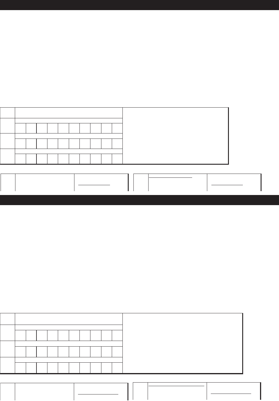
ADDENDUM
This supplement provides information not available at the time the instruction manual was printed and/or corrects erroneous
information appearing in the instruction manual.
Sub-audible tone functions (Tone/ CTCSS/ DCS) in Satellite mode:
FM sub-audible tone functions (Tone/ CTCSS/ DCS) can be enabled in Satellite mode and the Tone On/Off status can be stored in
each Satellite memory channel.
• Although the Tone On/Off status is stored in each Satellite memory channel, the sub-audible tone frequency/ code cannot be stored
due to limited memory capacity. The tone frequency/ code configuration from the normal VFO (VFO-A or VFO-B) is used instead.
• The tone frequency/ code search function cannot be operated in Satellite mode.
• Encoding and decoding is performed according to the data from the uplink frequency band.
TS-2000XE specifications:
For the frequency range of the transmitter (page 105) and receiver (page 106), refer to “E-type” under the TS-2000/ TS-B2000
column. Other specifications remain unchanged.
TS-2000E/ E2, TS-B2000E/ E2, and TS-2000XE specifications:
The 7 MHz band frequency range of the transmitter (page 105) has been expanded to “7.0 MHz - 7.2 MHz”.
AI Commands:
The TS-2000/ TS-B2000 transceivers do not support the following old AI commands: "AI 1;" and "AI 3;". There may be
incompatibilities between the transceiver and your PC logging software; changes may not be reflected when using these commands.
IA
.FFO/NOnoitcnuf)IA(noitamrofnIotuAehtsdaerrosteS :sretemaraP
1P
FFOIA:0
NOsitamrofIAdednetxE:2
reviecsnarteht,detcelessitamrofIAdednetxeehtnehW
.sretemarapehtsdnesyllacitamotua
:etoN
nidetroppustonera)sdnammocIAdlo(”;3IA“dna”;1IA“
.0002B-ST/0002-STeht
teS
12345678901
A I 1P ;
daeR
12345678901
A I ;
rewsnA
12345678901
A I 1P ;
IF Commands and OI Commands:
SUPLEMENTO
Este suplemento contiene información no disponible en la fecha que se imprimió el manual de instrucciones y/o corrige información
errónea que aparecía en dicho manual.
Funciones de tono subaudible (Tono/ CTCSS/ DCS) en modo Satélite:
Las funciones de tono subaudible en FM (Tono/ CTCSS/ DCS) se pueden activar en el modo Satélite, y el estado de tono activado/
desactivado se puede guardar en cada canal de memoria Satélite.
• Aunque el estado de tono activado/desactivado se guarda en cada uno de los canales de memoria Satélite, el código/frecuencia
de tono subaudible no se puede guardar debido a la capacidad limitada de memoria. En su lugar, se utiliza la configuración de
código/ frecuencia de tono del VFO normal (VFO-A o VFO-B).
• La función de búsqueda de código/ frecuencia de tono no se puede utilizar en el modo Satélite.
• La codificación y decodificación se realiza con arreglo a los datos de la banda de frecuencia ascendente.
Especificaciones de TS-2000XE:
Para conocer el rango de frecuencias del transmisor (página 105) y del receptor (página 106), consulte el “Tipo E” en la columna del
TS-2000/ TS-B2000. Otras especificaciones permanecen invariables.
Especificaciones del TS-2000E/ E2, TS-B2000E/ E2 y TS-2000XE:
El rango de frecuencias de la banda de 7 MHz del transmisor (página 105) se ha ampliado hasta “7,0 MHz – 7,2 MHz”.
Comandos AI:
Los transceptores TS-2000/TS-B2000 no soportan los siguientes comandos Al antiguos: "AI 1;" y "AI 3;". Puede haber
incompatibilidades entre el transceptor y el software de registro de su PC; no se producirán cambios cuando se utilicen estos
comandos.
IA
nóicamrofnIednóicnufaledodatseleeeloavitcased/avitcA
.)IA(acitámotuA
:sortemáraP
1P
odavitcasedlA:0
odavitcaátseodidnetxeIAotamrofleetnemaloS:2
aívnerotpecsnartle,odidnetxeIAotamrofleanoiccelesesodnauC
.etnemacitámotuasortemárapsol
:atoN
noson)sougitnaIAsodnamoc(”;3IA“y”;1IA“sodnamocsoL
.0002B-ST/0002-STleropsodatropos
-elbatsE
rec
12345678901
A I 1P ;
reeL
12345678901
A I ;
-nopseR
red
12345678901
A I 1P ;
B59-2409-10
FI
.sutatsreviecsnartehtseveirteR :sretemaraP
21P
tilpS:1,xelpmiS:0
❈.degnahcsiecnetnessihT
IO
noitamrofnIdnaBetisppO
❈.degnahcsiecnetnessihT
:sretemaraP
21P
tilpS:1,xelpmiS:0
❈.degnahcsiecnetnessihT
Comandos IF y Comandos OI:
FI
.rotpecsnartledodatselearepuceR :sortemáraP
21P
adidiviD:1,xelpmíS:0
❈.aibmacesnóicaroatsE
IO
adnabaledataeuponóicamrofnI
❈.aibmacesnóicaroatsE
:sortemáraP
21P
adidiviD:1,xelpmíS:0
❈.aibmacesnóicaroatsE

SUPPLÉMENT
Ce supplément contient des informations qui n’étaient pas disponibles au moment de l’impression du mode d’emploi
et/ou corrige des informations erronées contenues dans ce mode d’emploi.
Les fonctions des tonalités sub-audibles (Tonalité/ CTCSS/ DCS) en mode satellite :
Les fonctions de tonalité sub-audibles FM (Tonalité/ CTCSS/ DCS) peuvent être activées en mode satellite et l’état Tonalité
activé/désactivé peut être sauvegardé dans chaque canal de mémoire satellite.
• Bien que l’état de la tonalité activé/désactivé soit sauvegardé dans chaque canal de mémoire satellite, la tonalité de fréquence/
code sub-audible ne peut être enregistrée du fait de la capacité mémoire limitée. La tonalité de fréquence/configuration de code
du VFO normal (VFO-A ou VFO-B) est plutôt utilisée.
• La fonction de recherche de tonalité de fréquence/ code ne peut être effectuée en mode satellite.
• Le codage et le décodage sont effectués selon les données de la bande de fréquence de la liaison montante.
Caractéristiques du modèle TS-2000XE :
Pour la plage de fréquences de l’émetteur (page 105) et du récepteur (page 106), reportez-vous à “Type E” dans la colonne
TS-2000/ TS-B2000. Les autres caractéristiques restent inchangées.
Caractéristiques des modèles TS-2000E/ E2, TS-B2000E/ E2 et TS-2000XE :
La plage de fréquences de la bande 7 MHz de l’émetteur (page 105) a été élargie à “7,0 MHz – 7,2 MHz”.
SUPPLEMENTO
Questo supplemento fornisce informazioni non disponibili quando è stato stampato il manuale di istruzioni e/o contiene
correzioni su informazioni errate pubblicate sul manduale di istruzioni.
Funzioni di tono sotto-udibile (Tono/ CTCSS/ DCS) in modalità satellite:
Le funzioni di tono sotto-udibile (Tono/ CTCSS/ DCS) possono essere abilitate in modalità satellite e lo stato di tono attivato/
disattivato può essere memorizzato in ciascun canale di memoria satellite.
• Anche se lo stato di tono attivato/disattivato è memorizzato in ogni canale di memoria satellite, la frequenza di tono sotto-udibile/
codice non può essere memorizzata a causa della capacità di memoria limitata. Viene invece utilizzata la configurazione di
frequenza tono/ codice da VFO (VFO-A o VFO-B) normale.
• La funzione di ricerca della frequenza di tono/ codice non può essere utilizzata in modalità satellite.
• La codifica e la decodifica viene eseguita secondo i dati dalla banda di frequenza superiore.
Specifiche TS-2000XE:
Per la gamma di frequenza del trasmettitore (pagina 105) e ricevitore (pagina 106), fare riferimento a “Tipo E” nella colonna TS-2000/
TS-B2000. Le altre specifiche restano invariate.
Specifiche TS-2000E/ E2, TS-B2000E/ E2, e TS-2000XE:
La gamma di frequenza della banda a 7 MHz del trasmettitore (pagina 105) è stata ampliata a “7,0 MHz - 7,2 MHz”.
NACHRAG
Dieser Nachtrag enthält Informationen, die zum Zeitpunkt der Drucklegung der Bedienungsanleitung noch nicht
verfügbar waren, und/oder Korrekturen für fehlerhafte Informationen in der Bedienungsanleitung.
Sub-Ton-Funktionen (Ton/ CTCSS/ DCS) im Satellitenmodus:
FM-Sub-Ton-Funktionen (Ton/ CTCSS/ DCS) können im Satellitenmodus aktiviert werden; der Tone An/Aus -Status kann in
jedem Satellitenspeicherkanal festgehalten werden.
• Obwohl der Tone An/Aus -Status in jedem Satellitenspeicherkanal festgehalten wird, ist Sub-Ton-Frequenz/ Code-Speicherung
wegen begrenzter Speicherkapazität nicht möglich. Stattdessen wird die Ton-Frequenz/ Code-Konfiguration vom normalen VFO
(VFO-A oder VFO-B) verwendet.
• Die Ton-Frequenz/ Code-Suchfunktion kann im Satellitenmodus nicht eingesetzt werden.
• Codierung und Decodierung erfolgen gemäß Daten vom Uplink-Frequenzband.
Technische Daten des TS-2000XE:
Zum Frequenzbereich des Senders (Seite 105) und des Empfängers (Seite 106) siehe „E-Typ“ in der Spalte TS-2000/ TS-B2000.
Die übrigen technischen Daten bleiben unverändert.
Technische Daten des TS-2000E/ E2, TS-B2000E/ E2 und TS-2000XE:
Der Frequenzbereich des Senders (Seite 105) im 7-MHz-Frequenzband wurde auf „7,0 MHz – 7,2 MHz“ erweitert.
TOEVOEGSEL
Deze bijlage bevat informatie die niet beschikbaar was ten tijde van de druk van de gebruiksaanwijzing en/of
gecorrigeerde informatie die foutief is opgenomen in dezelfde gebruiksaanwijzing.
Subaudio-toonfuncties (Toon/ CTCSS/ DCS) in Satelliet-modus:
U kunt FM subaudiotonen (Toon/ CTCSS/ DCS) inschakelen in Satelliet-modus en de Toon Aan/Uit status opslaan in ieder
Satelliet-geheugenkanaal.
• Hoewel de Toon Aan/Uit status is opgeslagen in ieder Satelliet-geheugenkanaal, kunt u de subaudiotoon-frequentie/code niet
opslaan wegens beperkte geheugencapaciteit. Hiervoor in de plaats gebruikt u de configuratie van de toonfrequentie/code van
de normale VFO (VFO-A of VFO-B).
• De zoekfunctie van de toonfrequentie/code kunt u niet gebruiken in Satelliet-modus.
• Codering en decodering gebeurt volgens de gegevens van de uplink-frequentieband.
Specificaties TS-2000XE:
Raadpleeg “E-type” voor het frequentiebereik van de zender (pagina 105) en de ontvanger (pagina 106) onder de kolom TS-2000/
TS-B2000. Andere specificaties blijven ongewijzigd.
Specificaties TS-2000E/ E2, TS-B2000E/ E2 en TS-2000XE:
Het frequentiebereik van de 7 MHz-band van de zender (pagina 105) is vergroot tot “7,0 MHz – 7,2 MHz”.
