Kenwood Vrs 7100 Owner S Manual
VRS-7100 to the manual 2575976e-468f-4f84-c920-af7f70a506bc
2014-07-06
: Kenwood Kenwood-Vrs-7100-Owner-S-Manual kenwood-vrs-7100-owner-s-manual kenwood pdf
Open the PDF directly: View PDF ![]() .
.
Page Count: 64

B60-5462-10 02 MA ( K, P, E, X ) 0312
AUDIO VIDEO SURROUND RECEIVER
VRS-7100
INSTRUCTION MANUAL
KENWOOD CORPORATION
About the supplied remote control
Compared to standard remote controls, the remote control supplied with this receiver has
several operation modes. These modes enable the remote control to control other audio/video
components. In order to effectively use the remote control it is important to read the operating
instructions and obtain a proper understanding of the remote control and how to switch its
operation modes (etc.).
Using the remote control without completely understanding its design and how to switch the
operation modes may result in incorrect operations.
Quick Start Reference
Please read the following pages so that you can enjoy the surround sound at the best
condition.
(These pages give shortcut explanations on how to connect the speaker system to the
receiver, set up the speakers and play a source.)
"Let's play DVD video software" )¡, ™£
2 EN
Units are designed for operation as follows.
Before applying power
Caution : Read this page carefully to ensure safe operation.
U.S.A. and Canada ........................................... AC 120 V only
Australia ........................................................... AC 240 V only
Europe ............................................................... AC 230 V only
THE EXCLAMATION POINT WITHIN AN EQUILATERAL TRIANGLE IS INTENDED TO ALERT THE USER TO
THE PRESENCE OF IMPORTANT OPERATING AND MAINTENANCE (SERVICING) INSTRUCTIONS IN THE
LITERATURE ACCOMPANYING THE APPLIANCE.
THE LIGHTNING FLASH WITH ARROWHEAD SYMBOL, WITHIN AN EQUILATERAL TRIANGLE, IS INTENDED
TO ALERT THE USER TO THE PRESENCE OF UNINSULATED “DANGEROUS VOLTAGE” WITHIN THE PROD-
UCT’S ENCLOSURE THAT MAY BE OF SUFFICIENT MAGNITUDE TO CONSTITUTE A RISK OF ELECTRIC
SHOCK TO PERSONS.
CAUTION: TO REDUCE THE RISK OF ELECTRIC SHOCK, DO
NOT REMOVE COVER (OR BACK). NO USER-SERVICEABLE
PARTS INSIDE. REFER SERVICING TO QUALIFIED SERVICE
PERSONNEL.
Safety precautions
WARNING : TO PREVENT FIRE OR ELECTRIC SHOCK, DO NOT EXPOSE
THIS APPLIANCE TO RAIN OR MOISTURE.
CAUTION
RISK OF ELECTRIC SHOCK
DO NOT OPEN
*5462/01-07/EN 04.4.13, 8:00 PM2
3 EN
Before applying the power
How to use this manual
This manual is divided into four sections, Preparations, Operations,
Remote Control,and Additional Information.
Preparations
Shows you how to connect your audio and video components to the
receiver and prepare the surround processor. Since this receiver works
with all your audio and video components, we will guide you in setting up
your system to be as easy as possible.
Operations
Shows you how to operate the various functions available on the
receiver.
Remote Control
Shows you how to operate other components using the remote control,
as well as a detailed explanation of all remote control operations.Once
you have registered your components with the proper setup codes,you
’ll be able to operate both this receiver and your other AV components
(TV, VCR, DVD player, CD player, etc.)using the remote control supplied
with this receiver.
Additional Information
Shows you additional information such as "In case of difficulty" (trouble
shooting) and "Specifications".
Maintenance of the unit
When the front panel or case becomes dirty, wipe with a soft, dry
cloth. Do not use thinner, benzine, alcohol, etc. for these agents may
cause discoloration.
In regard to contact cleane
Do not use contact cleaners because it could cause a malfunction. Be
specially careful not to use contact cleaners containing oil, for they
may deform the plastic component.
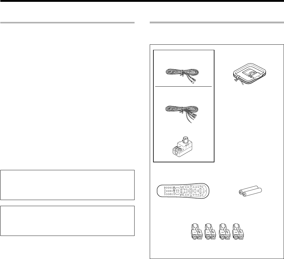
Unpacking
Unpack the unit carefully and make sure that all the accessories
are present.
FM indoor antenna (1)
AM loop antenna (1)
Remote control unit
(1)
Batteries (R6/AA)
(2)
Speaker cord connectors
(4)
If any accessories are missing, or if the unit is damaged or fails
to operate, notify your dealer immediately. If the unit was
shipped to you directly, notify your shipper immediately. Kenwood
recommends that you retain the original carton and packing
materials in case you need to move or ship the unit in the future.
Keep this manual handy for future reference.
For Europe and Australia only
(For the U.S.A. and Canada)
FM indoor antenna (1)
(For Europe and Australia)
Antenna adaptor (1)

4 EN
Before applying the power
Special features
True home theater sound
‡
~
·
This receiver incorporates a wide variety of surround modes to bring you
maximum enjoyment from your video software. Select a surround mode
according to your equipment or the software you are going to play and enjoy!
÷Dolby Digital EX
÷Dolby PRO LOGIC IIx, Dolby PRO LOGIC II
÷Dolby Digital
÷DTS-ES
÷DTS NEO:6
÷DTS 96/24
÷DTS
÷DSP Mode
÷Dolby Virtual Speaker
÷Dolby Headphone
GAME mode function
¶
When you connect a game machine to the GAME jacks on the front
panel, the input selector of the receiver switches automatically to
"GAME" and the optimum sound field for enjoying games is set.
This feature improves your convenience in playing video games.
DUAL SOURCE function
º
While you enjoy audio listening through the speakers, another person
can enjoy another source (audio + video) through headphones by
connecting the source to the GAME, FRONT AUX jacks.
ACTIVE EQ
⁄
ACTIVE EQ mode will produce a more dynamic sound quality in any
condition.You can enjoy a more impressive sound effect when ACTIVE
EQ is turned on during Dolby Digital and DTS playback.
Remote control
t
In addition to the basic receiver, the remote control supplied with this
receiver can also operate almost all of your remote controllable audio and
video components. Just follow the simple setup procedure to register
the components you have connected.
RDS (Radio Data System) tuner (For Europe)
fi
The receiver is equipped with an RDS tuner that provides several
convenient tuning functions: RDS Auto Memory, to automatically preset
up to 40 RDS stations broadcasting different programs; station name
display, to show you the name of the current broadcast station; and PTY
search to let you tune stations by program type.
PTY (Program TYpe) search (For Europe)
fl
Tune the stations by specifying the type of program you want to hear.
*5462/01-07/EN 04.4.13, 8:00 PM4
5 EN
Before applying the power
Contents
Caution : Read the pages marked carefully to ensure safe operation.
Before applying power ........................................... 2
Safety precautions ............................................... 2
How to use this manual ............................................. 3
Unpacking .................................................................. 3
Special features ......................................................... 4
Contents .................................................................... 5
Names and functions of parts...................................... 6
Main unit .................................................................... 6
Remote control unit ................................................... 7
Setting up the system ............................ 8
Connecting a DVD player ............... 9
Connecting video components,
audio components ........................ 10
Digital connections ....................... 12
Connecting the speakers ............. 13
Connecting the speaker terminals ...
15
PRE OUT connections.................. 16
Connecting to the GAME jacks /
FRONT AUX jacks ........................ 17
Connecting the antennas ............. 18
Preparing the remote control ....... 19
Let’s play DVD video software
(For U.S.A. and Canada) ................... 20
Let’s play DVD video software
(For Europe and Australia) .............. 22
Preparing for playback ......................... 24
Speaker settings .......................... 24
Re-assignment of rear panel jacks ...
28
Normal playback ................................... 29
Listening to a source component ...
29
Listening with headphones .......... 30
Adjusting the sound ..................... 30
Recording .............................................. 32
Analog sources ............................. 32
Digital sources .............................. 32
Listening to radio broadcasts .............. 33
Tuning (non-RDS) radio stations ... 33
Presetting radio stations .............. 33
Receiving preset stations ............. 34
Receiving preset stations in order
(P.CALL) ........................................ 34
Using RDS (Radio Data System)
(For Europe only) .................................. 35
Using the RDS Disp. (Display) key ...
35
Tuning by Program TYpe
(PTY search) ................................. 36
Ambience effects .................................. 37
Surround modes ........................... 37
Virtual modes ............................... 39
Surround play ............................... 40
Convenient functions ........................... 42
Basic remote control operations for
other components ................................ 45
Registering setup codes for other
components ................................. 45
Searching for your code ............... 45
Checking the codes ...................... 46
Re-assigning device keys ............. 46
Operating other components ....... 46
Clearing all of the settings registered or
stored in the remote control unit .....
46
Setup code chart (RC-R0730) (For
U.S.A., Canada and Australia) ...... 47
Setup code chart (RC-R0730E) (For
Europe) ......................................... 51
DVD player , MD recorder CD player
& TV operations ........................... 58
VCR , Satellite receiver & Cable con-
verter operations ......................... 59
In case of difficulty................................ 60
Specifications ........................................ 62
Remote
Control
Addi
t
i
ona
l
Information
Operations
Preparations
Operations
*5462/01-07/EN 04.4.13, 8:00 PM5
6 EN
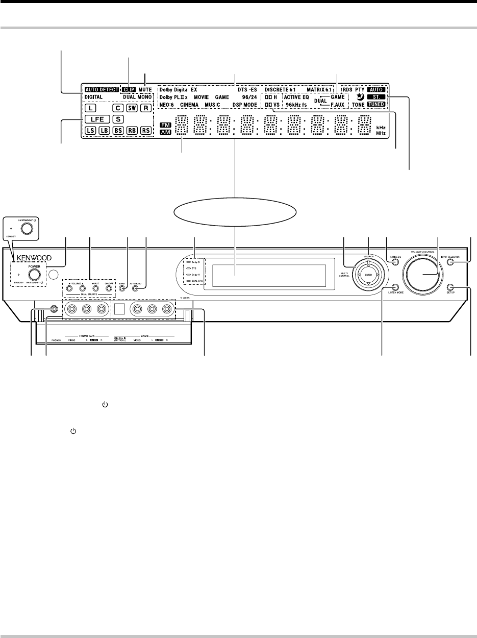
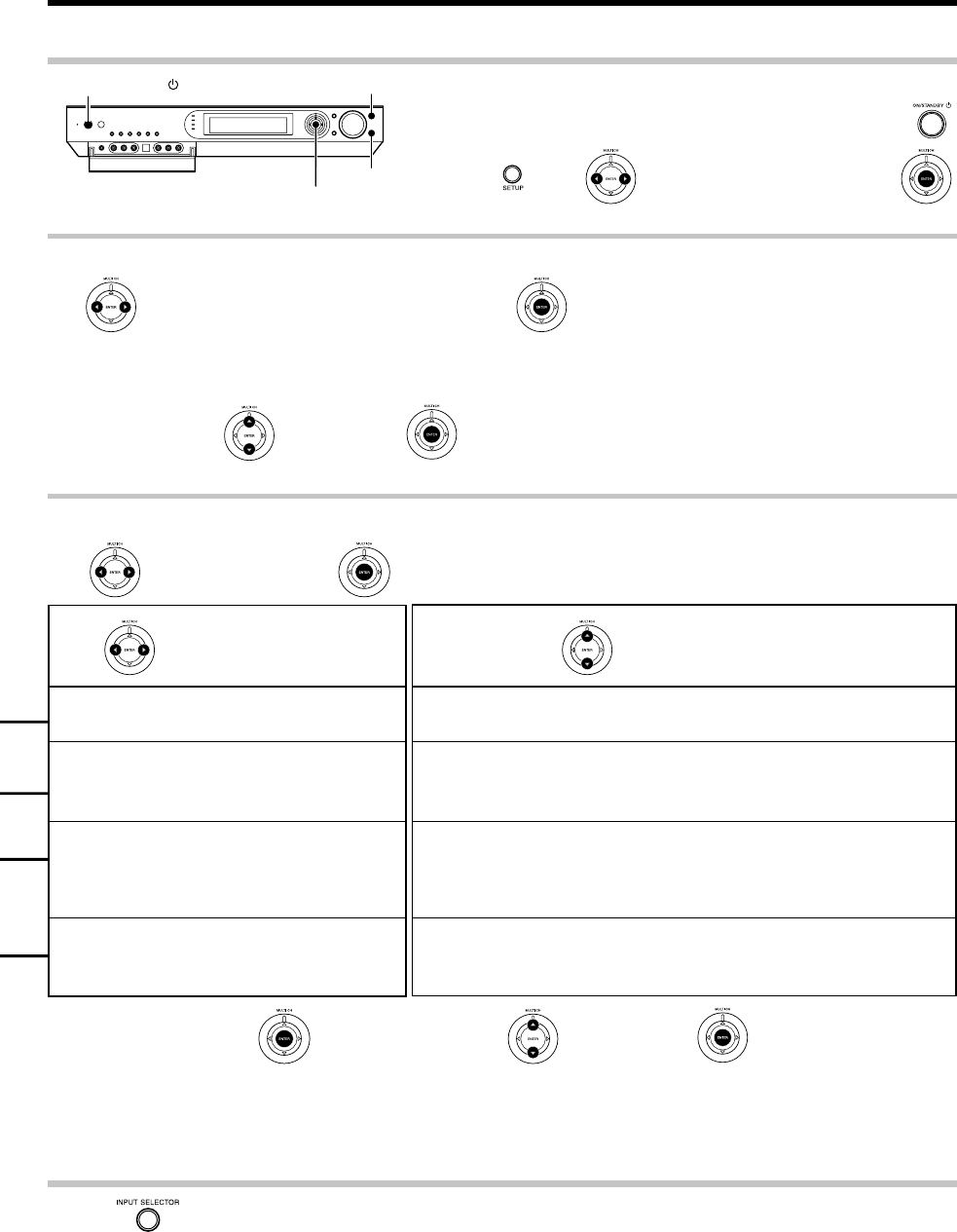
34 5 6 7821 09
#!$ @%
Standby mode
While the standby indicator is lit, a small amount of power is supplied to the system to back up the memory. This is called standby mode. Under the
condition, the system can be turned ON by the remote control unit.
1(For the U.S.A. and Canada)
POWER ON/STANDBY key ¢
Use to turn the power ON/STANDBY.
(For Europe and Australia)
ON/STANDBY key ¢
Use to turn the power ON/STANDBY.
STANDBY indicator
Lights when the power is in the standby
mode.
2DUAL SOURCE VOLUME 5/∞ keys
º
Use to adjust the volume in the DUAL
SOURCE mode.
DUAL SOURCE INPUT key º
Use to select the input for the DUAL SOURCE
mode.
DUAL SOURCE ON/OFF key º
Use to switch the DUAL SOURCE mode ON/
OFF.
3BAND key ‹
Use to select the broadcast band.
4AUTO/MONO key ‹
Use to select the auto or manual tuning
mode.
5Dolby D indicator ‚
Lights when the receiver is in the Dolby
Digital mode.
DTS indicator ‚
Lights when the receiver is in the DTS mode.
Dolby H indicator ·
Lights when the Dolby H mode is ON.
DUAL SRC indicator º
Lights when the DUAL SOURCE mode is
ON.
6Joystick
MULTI CONTROL % / fi
¡£‹
Use to control a variety of settings. Use to
tuning of radio broadcasting.
MULTI CONTROL @ / #
¡£›
Use to control a variety of settings. Use to
selection of preset radio stations.
ENTER ¡£‹
Use to control a variety of settings. Use to
presetting of radio stations.
7MULTI CH indicator ‚
Lights during multi-channel playback.
Display
Speaker selection indicators,
Input channel indicators (The Input channel
indicators lights up to indicate the channels
contained in the input signal. The "S" indicator
lights when the surround component consists
of a single channel.)
ACTIVE EQ indicator,
DUAL SOURCE Input indicator,
96 kHz fs indicator
Frequency display,
Input display, Preset
channel display,
Listen mode display
MUTE indicator
CLIP indicator
Input mode indicators
Listen mode indicators
8ACTIVE EQ key ⁄
Use to select ACTIVE EQ's setting.
9VOLUME CONTROL knob ª
Use to adjust the receiver volume.
0INPUT SELECTOR key ª
Use to select input sources.
!SETUP key ¡£¤
Use to select the speakers'settings etc.
Use to select the REC MODE.
@LISTEN MODE key ‚
Use to select the listening mode.
#GAME jacks &¶º
$FRONT AUX jacks &º
%PHONES jack º
Use for headphone listening.
AUTO indicator, ST. indicator,
TUNED indicator, Sleep Timer indicator,
TONE indicator
For Europe Only :
RDS indicator, PTY indicator
Dolby Headphone mode indicator,
Dolby Virtual Speaker mode indicator
View when the GAME/ FRONT AUX jack
cover is open.
Main unit
Names and functions of parts
For Europe and Australia
*5462/01-07/EN 04.4.13, 8:00 PM6
7 EN
TV Mute key
Use to temporarily mute the TV sound.
6Input Mode key 8
Use to switch between the full auto, digital and
analog input.
7Audio key
Use to operate the DVD component.
8Angle key
Use to operate the DVD component.
9Page 5/∞ keys
Use to operate the DVD component.
(For Europe only)
RDS Disp. key
Use to receive RDS broadcast.
PTY key
Use for PTY search.
0CH +/
-
keys
Use to select the channels.
¢ / 4 keys
If CD, MD or DVD is selected as the input
source, these keys function as skip keys.
!Mute key ⁄
Use to temporarily mute the sound.
Sound key •ºw
Use to adjust the sound quality and the ambi-
ence effects.
@TV VOL +/
-
keys
Use to adjust the TV’s volume.
#8 key
Use to operate other components.
Dimmer key r
Use to adjust the brightness of the display.
1Input Selector keys (TUNER, DVD, VID 1,
VID 2, AUX, F. AUX, Game) ª
Use to select input sources.
Sources keys (TUNER, DVD, VID 1, VID 2,
AUX, F. AUX, Game) t
To control one of the registered sources without
switching the receiver's input selector to that
source, press and hold the desired input selector
key for more than 3 seconds.
Net Mode key, M.Card Mode key
Availability may differ depending on the coun-
try and sales area.
2RCV (receiver) Mode key ¢w
Use to switch the remote control to the
receiver control mode.
3SRC (source) Power key
Use to turn the other components ON/OFF.
4Numeric keys ›t
Use to selection of preset radio stations.
Use to operate other components.
Multi (%/fi) keys ¢‹
Use to control a variety of settings as well as in
tuning of radio broadcasting. Use to operate
other components.
P.Call @/# keys ¢›
Use to control a variety of settings.
Use to selection of preset radio stations.
Enter key ¢
Use to control a variety of settings.
Use to operate other components.
5+100 key
Use to select MD tracks when the remote
control controls the MD recorder.
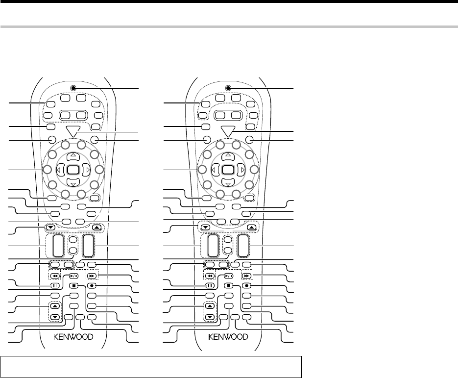
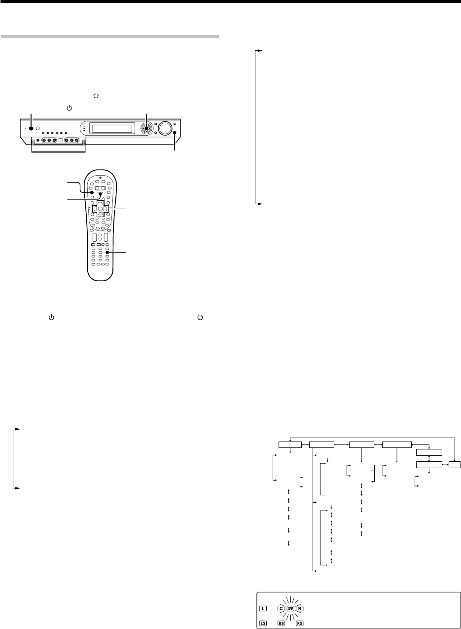
Remote control unit
Names and functions of parts
S
R
C
P
o
w
e
r
T
V
P
o
w
e
r
5
6
8
9
4
3
2
1
0
7
Dimmer
Tune – Tune +Band
Setup
Last
Top Menu
Auto
Info
Listen Mode
Retern
Exit
Sound
Mute
TV
VOL
4
¢
VOL
+
–
CH
+
–
Menu
Sleep
Disc Skip
Input Sel.
Disk Sel.
OSD
Guide
Page
TV Mute
Angle
Audio Subtitle
+ 10+
100
Multi
Multi
P. Call
P. Call
Enter
Game
RCV
Mode
POWER
RCVR
VID2
VID1
DVD
AUX
F.AUX
TUNER
Net
Mode
M.Card
Mode
– +
TV Input
TV
Stereo
Dolby
Virtual
Active
EQ
1
2
3
8
9
£
∞
º
⁄
¤
™
6
5
4
7
0
!
$
)
¡
¢
ª
§
¶
•
%
^
@
Input
Mode
&
(
*
#
›
fi
‹
Remote
Setup
$3/8 key
If CD is selected as the input source, this key
functions as the play/pause key. If DVD, MD or
VCR is selected as the input source, this key
functions as the play key.
Band key ‹
Use to select the broadcast band.
%Return key
Use to operate the DVD component.
Exit key
Use to operate other components.
^Listen Mode 5/∞ keys ‚
Use to select the listening mode.
&Info key
Use to operate other components.
*Dolby Virtual key ·
Use to select the Dolby Virtual mode.
(Active EQ key ⁄
Use to select ACTIVE EQ ’s setting.
)LED indicator
Blinks to show that signals are being transmitted.
¡POWER RCVR (receiver) key ¢
Use to turn the receiver ON/STANDBY.
™TV Power key
Use to turn the TV on and off.
£Menu key
Use to operate other components.
Sleep key r
Use to set the Sleep timer.
¢Subtitle key
Use to operate the DVD component.
∞OSD key
Use to operate the DVD component.
Guide key
Use to operate other components.
§VOL +/
-
keys ª
Use to adjust the receiver volume.
¶TV Input key
Use when in TV operation.
•TV key
Use when in TV operation.
ª1 / ¡ keys
If CD, MD or DVD is selected as the input
source, these keys function as search key.
Tune +/
-
keys ‹
Use to tuning of radio broadcasting.
º¶ key
If MD or VCR is selected, this key functions as
record key.
If VCR is selected, this key functions as record
key when it is pressed twice sequentially.
Top Menu key
Use to operate the DVD component.
Setup key ¢
Use to select the speakers ’ settings etc.
⁄Disc Sel. key
Use to operate other components.
Input Sel. key
Use to operate other components.
¤Disc Skip key
If CD is selected as the input source, this key
functions as the multi-CD player disc skip key.
Last key
Use to operate other components.
‹7 key
If CD, MD or DVD is selected as the input
source, this key functions as the stop key.
Auto key ‹
Use to select the auto or manual tuning mode.
›Remote Setup key ty
Use to register other components.
fiStereo key q
Use to switch the listen mode temporary to
the stereo mode.
If the name of a function is different on the receiver and on the remote control, the name of the remote
control key in this manual is indicated in parentheses.
This remote control unit can be use not only for Kenwood products but also for other non-Kenwood products by setting the appropriate manufacturer’s
setup codes. u
S
R
C
P
o
w
e
r
T
V
P
o
w
e
r
5
6
8
9
4
3
2
1
0
7
Dimmer
Tune –Tune +Band
Setup
Last
Top Menu
Auto
Info
Listen Mode
Retern
Exit
Sound
Mute
TV
VOL
4
¢
VOL
+
–
CH
+
–
Menu
Sleep
Disc Skip
Input Sel.
Disk Sel.
OSD
Guide
Page
TV Mute
Angle
Audio Subtitle
+ 10+
100
Multi
Multi
P. Call
P. Call
Enter
Game
RCV
Mode
POWER
RCVR
VID2
VID1
DVD
AUX
F.AUX
TUNER
Net
Mode
M.Card
Mode
–+
TV Input
TV
Stereo
Dolby
Virtual
Active
EQ
1
2
3
8
£
∞
º
⁄
¤
™
6
5
4
7
0
!
$
)
¡
¢
ª
§
¶
•
%
^
@
Input
Mode
&
(
*
#
›
fi
‹
Remote
Setup
RDS Disp.
PTY
9
For Europe : RC-R0730E
For the U.S.A., Canada and Australia: RC-R0730
*5462/01-07/EN 04.4.13, 8:00 PM7
8 EN
Input mode settings
DVD, VIDEO 1, VIDEO 2, AUX and GAME inputs each include jacks
for digital audio input and analog audio input.
The initial factory settings for audio signal playback for DVD,
VIDEO 1, VIDEO 2, AUX and GAME are full auto.
After completing connections and turning on the receiver,follow the
steps below.
Setting up the system
Input Mode
INPUT SELECTOR
Microcomputer malfunction
If operation is not possible or an erroneous display appears,even
though all connections have been made properly, reset the micro
computer referring to "In case of difficulty". P
Notes
1. Be sure to turn off the system components before connecting them.
2. Be sure to insert every connection cable completely into the jack.
Incomplete connection may result in absence of audio output or
production of noise.
3. Be sure to disconnect the power cord from the AC wall outlet before
inserting or removing a connection cable.
4. Installation of outdoor antenna is a dangerous work. Please have your
dealer or a specialized technician install it.
5. Select the speaker installation locations with care. If a speaker is
installed near a source of magnetism including a magnet, the mutual
interference with the speaker may produce color irregularities on the
TV screen.
Analog audio connections
Audio connections are made using RCA pin cords. These cables transfer
stereo audio signal in an "analog" form. This means the audio signal
corresponds to the actual audio of two channels. These cables usually
have 2 plugs on each end,one red for the right channel and one white for
the left channel.
These cables are to be prepared separately by the user.
Input Selector keys
1Use the INPUT SELECTOR key (or Input Selector keys)
to select DVD, VIDEO 1, VIDEO 2, AUX or GAME.
2Press the Input Mode key.
Each press switches the setting as follows:
1"F-AUTO": Auto detect
("AUTO DETECT" indicator lights up)
2"D-MANUAL": Fixed to digital input
("DIGITAL" indicator lights up)
3"ANALOG": Fixed to analog input *
("AUTO DETECT", "DIGITAL" indicator goes off)
*Can not be selected for DTS playback.
Auto detect:
In "F-AUTO (FULL AUTO)" mode ("AUTO DETECT" indicator light
up), the receiver detects the digital or analog input signals
automatically. The receiver will select the input mode and listen-
ing mode automatically during playback to match the type of input
signal (Dolby Digital, PCM, DTS) and the speaker setting. ‚
The "DIGITAL" indicator lights up when a digital signal is
detected. The "DIGITAL" indicator is extinguished when no
digital signal is detected.
Fixed to digital input:
Select this mode if you want to keep the decoding condition
(Dolby Digital, DTS, PCM, etc.) in the current listen mode.
When "D-MANUAL (DIGITAL MANUAL)" mode is selected, the
set listen modes may be changed automatically depending on the
listen mode. ‚
Fixed to analog input:
Select this setting to play analog signals from a VCR, etc.
If the Input Mode key is pressed quickly, sound may not be
produced. Press the Input Mode key again.
CAUTION
Be sure to adhere to the following, or proper ventilation will be
blocked causing damage or fire hazard.
÷Do not place any objects impairing heat radiation onto the top of
the unit.
÷Leave some space around the unit (from the largest outside
dimension including projection) equal to or greater than, shown
below.
Top panel : 50 cm
Side panel : 10 cm
Back panel : 10 cm
CAUTION
Make sure that the power cord plug is disconnected from the AC wall
outlet before proceeding to connections. Also be sure to disconnect the
power cord plug from the AC wall outlet before changing connections.
For the connections of other system components, see pages 9 to 18.
When connecting an associated system component, be sure to read
its instruction manual.
*5462/08-19/EN 04.4.13, 8:00 PM8
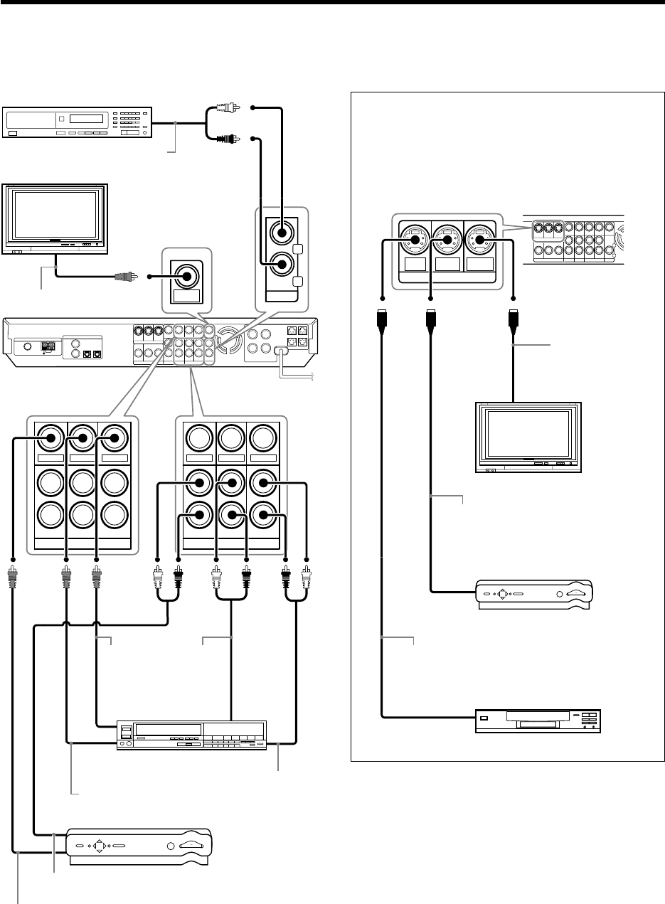
9 EN
DVD
IN
VIDEO
IN
VIDEO
IN
(ASSIGNABLE)
(ASSIGNABLE)
INPUT
COMPONENT
DIGITAL IN
IN 2
IN 1
Y C
B
C
R
OUTPUT
COMPONENT
VIDEO
Y CBCR
MONITOR
OUT
VIDEO
(VIDEO 2)
(DVD)
COAX 2
(VIDEO 2)
COAX 1
(DVD)
OPT 1
(VIDEO 1)
OPT 2
(AUX)
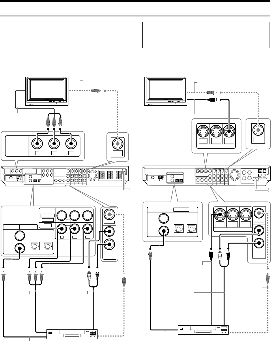
Setting up the system
Connecting a DVD player
DIGITAL OUT (AUDIO)
(Coaxial cord)
COMPONENT
VIDEO OUT
COMPOSITE
VIDEO OUT
(Yellow RCA
pin cords)
AUDIO LINE
OUT or
MIX LINE OUT
(Audio cord)
DVD player
COMPOSITE
VIDEO IN
(Yellow RCA
pin cords)
COMPONENT
VIDEO IN
Monitor TV
For U.S.A. and Canada
DVD
DVD
IN
VIDEO 2
IN
MONITOR
OUT
S VIDEO
IN
VIDEO
IN
DVD
IN
VIDEO 2
IN
MONITOR
OUT
S VIDEO
MONITOR
OUT
COAX 2
(VIDEO 2)
COAX 1
(DVD)
OPT 1
(VIDEO 1)
OPT 2
(AUX)
(ASSIGNABLE)
DIGITAL IN
DIGITAL OUT (AUDIO)
(Coaxial cord)
COMPOSITE
VIDEO OUT
(Yellow RCA
pin cords)
AUDIO LINE OUT or
MIX LINE OUT
(Audio cord)
S VIDEO OUT
(S VIDEO cord)
DVD player
COMPOSITE
VIDEO IN
(Yellow RCA pin cords)
S VIDEO IN
(S VIDEO cord)
Monitor TV
For Europe and Australia
÷Digital audio connections are required when playing multi-chan-
nel signals such as the Dolby Digital and DTS signals.
÷To play the DVD player connected in this page, select the "DVD"
input selector. ª
To AC wall outlet
To AC wall
outlet
If you have connected a DVD player to the receiver with digital connection,be
sure to read the "Input mode settings", "Re-assignment of rear panel
jacks" section carefully. 8•
*5462/08-19/EN 04.4.13, 8:00 PM9
10 EN
Setting up the system
AUX
IN
L
R
MONITOR
OUT
VIDEO 2 VIDEO 1
PLAY I N REC OUT PLAY IN
VIDEO
IN
VIDEO OUT
VIDEO
IN
VIDEO 2 VIDEO 1
PLAY I N REC OUT PLAY IN
VIDEO
IN
VIDEO OUT
VIDEO
IN
Satellite Cable Tuner
Video deck, Cassette
deck or MD recorder
Audio components
Monitor TV
VIDEO
OUT
(Yellow
RCA pin
cords)
AUDIO LINE OUT or MIX LINE OUT (Audio cord)
AUDIO
LINE
IN
(Audio
cord)
VIDEO IN
(Yellow RCA pin cords)
AUDIO LINE OUT (Audio cord)
AUDIO
LINE OUT
(Audio cord)
VIDEO OUT (Yellow RCA pin cords)
VIDEO IN (Yellow RCA pin cords)
FM 75 Ω
OUTPUT
COMPONENT
VIDEO
Y C
B
C
R
(ASSIGNABLE)
INPUT
COMPONENT
IN 2
IN 1
Y C
B
C
R
VIDEO
(VIDEO 2)
(DVD)
HDD Recorder, DVD Recorder,
Satellite Cable Tuner & Game
Player (with component jacks)
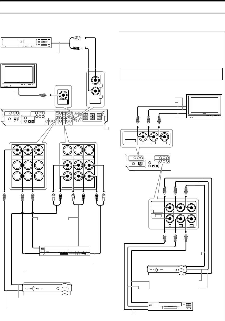
Connecting video components (COMPONENT VIDEO)
Monitor TV
(with component jacks)
DVD player (with component jacks)
Y OUT
CB OUT CR OUT
Y OUT
CB OUT
CR OUT
CB IN
Y IN
CR IN
If you have connected the receiver to a video component with
COMPONENT jacks, you can get a better picture quality than by
connecting to the S VIDEO jacks.
When connecting a video component with COMPONENT jacks,
see "Re-assignment of rear panel jacks"•
When connecting the TV to the COMPONENT jacks, be sure to
connect all the other components to the COMPONENT jacks.
For U.S.A. and Canada
Connecting video components, audio components
*5462/08-19/EN 04.4.13, 8:00 PM10
11 EN
Setting up the system
AUX
IN
L
R
MONITOR
OUT
VIDEO 2 VIDEO 1
PLAY I N REC OUT PLAY IN
VIDEO
IN
VIDEO OUT
VIDEO
IN
VIDEO 2 VIDEO 1
PLAY I N REC OUT PLAY IN
VIDEO
IN
VIDEO OUT
VIDEO
IN
Satellite Cable Tuner
Video deck, Cassette
deck or MD recorder
Audio components
Monitor TV
VIDEO
OUT
(Yellow
RCA pin
cords)
AUDIO LINE OUT or MIX LINE OUT (Audio cord)
AUDIO
LINE
IN
(Audio
cord)
VIDEO IN
(Yellow RCA pin cords)
AUDIO LINE OUT (Audio cord)
AUDIO
LINE OUT
(Audio cord)
VIDEO OUT (Yellow RCA pin cords)
VIDEO IN
(Yellow RCA pin cords)
Connecting video components (S VIDEO)
Use the S VIDEO jacks to make connections to video compo-
nents with S VIDEO IN/OUT jacks.
¶If you use the S VIDEO jacks to connect your video playback
components, be sure to use the S VIDEO jacks when con-
necting your monitor and video recording components.
DVD
IN
VIDEO 2
IN
MONITOR
OUT
S VIDEO
Satellite Cable Tuner
(with S VIDEO cord)
Monitor TV
(with S VIDEO jack)
DVD player
(with S VIDEO jack)
S VIDEO OUT (S VIDEO cord)
S VIDEO IN
(S VIDEO cord)
S VIDEO OUT (S VIDEO cord)
For Europe and Australia
*5462/08-19/EN 04.4.13, 8:01 PM11
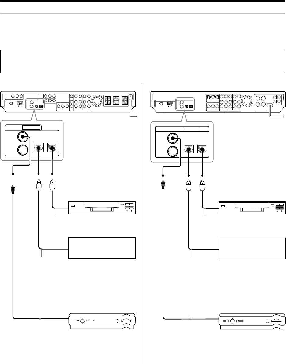
12 EN
(ASSIGNABLE)
DIGITAL IN
COAX 2
(VIDEO 2)
COAX 1
(DVD)
OPT 1
(VIDEO 1)
OPT 2
(AUX)
Digital connections
The digital in jacks can accept DTS,Dolby Digital,or PCM signals.Connect components capable of outputting DTS,Dolby Digital or PCM (CD)
digital signals.
If you have connected a DVD player to the receiver with digital connection,be sure to read the "Input mode settings", "Re-assignment of rear panel
jacks" section carefully. 8•
DTS disclaimer clause
When playing DTS-encoded discs, excessive noise will be exhibited from the analog stereo outputs of the CD or DVD player. To enjoy
DTS Digital Surround™ playback, this unit must be connected to the digital output of the CD or DVD player.
Setting up the system
Connect the analog audio signals
to the AUX jacks.
(See "Connecting video compo-
nents, audio components ". 0)
OPTICAL DIGITAL
OUT (AUDIO)
(Optical fiber cord)
Component with DTS,
Dolby Digital,or PCM
OPTICAL DIGITAL OUT
COAXIAL DIGITAL
OUT (AUDIO)
(Coaxial cord)
Connect the video signal and ana-
log audio signals to the VIDEO 2
jacks.
(See "Connecting video compo-
nents, audio components ". 0)
CD player or DVD player
OPTICAL DIGITAL OUT (AUDIO)
(Optical fiber cord)
Satellite Cable Tuner
For U.S.A. and Canada For Europe and Australia
COAX 2
(VIDEO 2)
COAX 1
(DVD)
OPT 1
(VIDEO 1)
OPT 2
(AUX)
(ASSIGNABLE)
DIGITAL IN
Connect the analog audio signals
to the AUX jacks.
(See "Connecting video compo-
nents, audio components ". !)
OPTICAL DIGITAL
OUT (AUDIO)
(Optical fiber cord)
Component with DTS,
Dolby Digital,or PCM
OPTICAL DIGITAL OUT
COAXIAL DIGITAL
OUT (AUDIO)
(Coaxial cord)
Connect the video signal and ana-
log audio signals to the VIDEO 2
jacks.
(See "Connecting video compo-
nents, audio components ". !)
CD player or DVD player
OPTICAL DIGITAL OUT (AUDIO)
(Optical fiber cord)
Satellite Cable Tuner
*5462/08-19/EN 04.4.13, 8:01 PM12
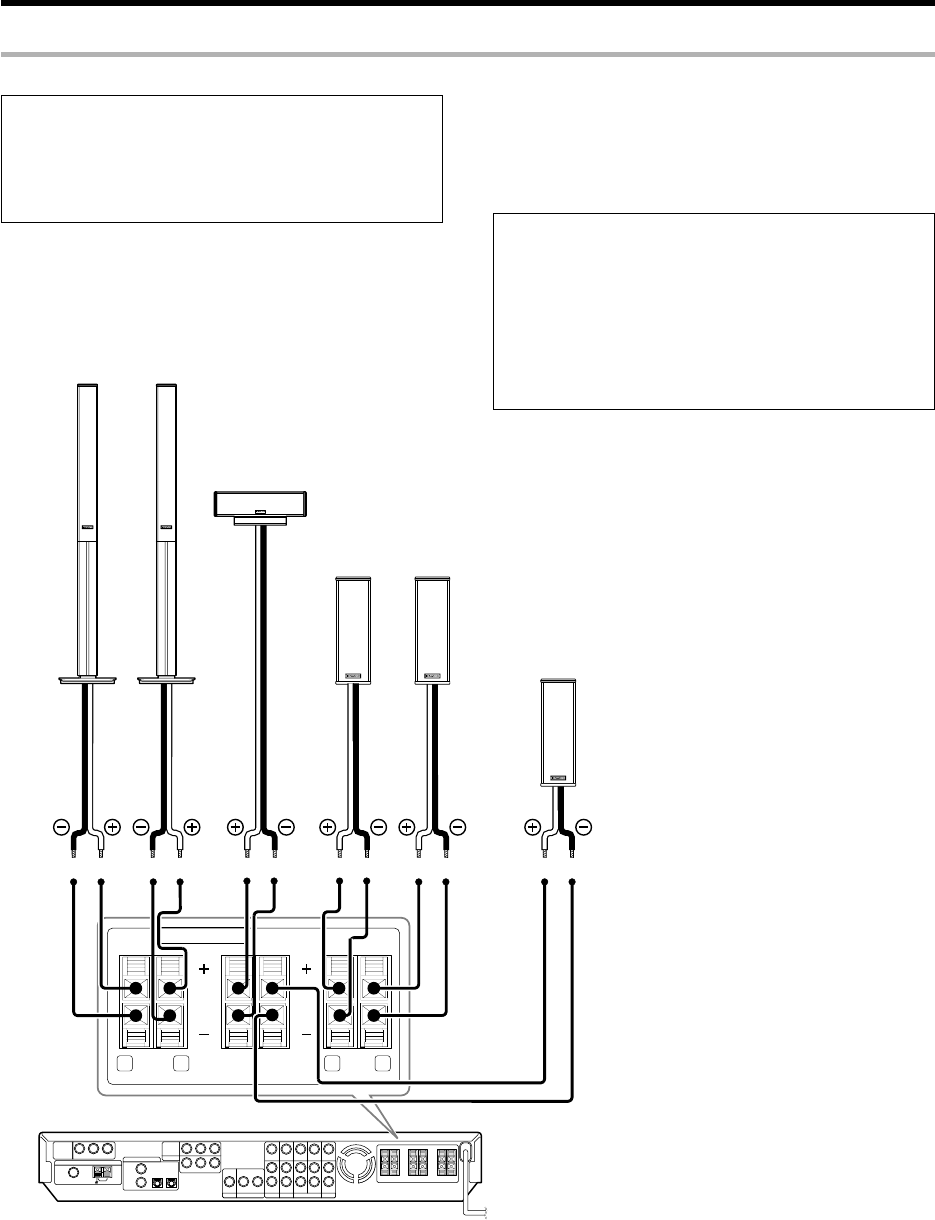
13 EN
Connecting the speakers
Setting up the system
SPEAKERS (6
-
8Ω)
RR LFRONT R LSURRCENTER
SURR BACK
/SW
Front Speakers
Surround Speakers
Be sure to connect both surround speakers
Subwoofer/ Surround Back Speaker
When the surround back speaker is connected to these
terminals, set the speaker setting to
"BS/SW BS".
In this case, the subwoofer should be connected to the
PRE OUT SUBWOOFER jack ^
Center
Speaker
LeftRight
Left
Right
Whether each speaker is connected properly can be
confirmed by outputting the test tone and checking if
each speaker channel outputs audio. For details, see
"Speaker settings" (Step 6 Adjust the speaker volume
level). §
For U.S.A. and Canada
CAUTION
Make sure that the power cord plug is disconnected from the AC
wall outlet before proceeding to speaker cord connections.
If the conductor wires on the extremity of speaker cord are
untwisted, there is a risk of short-circuiting. Be sure to twist
them well before connecting the speaker cord.
Protection circuitry
This unit incorporates protection circuitry, which may be activated
during high-power reproduction or in case of extreme rise in tempera-
ture.
When the protection circuitry is activated, the output from this unit is
shut down and the STANDBY indicator blinks.
In this case, turn this unit OFF then ON again and reduce the output
volume level.
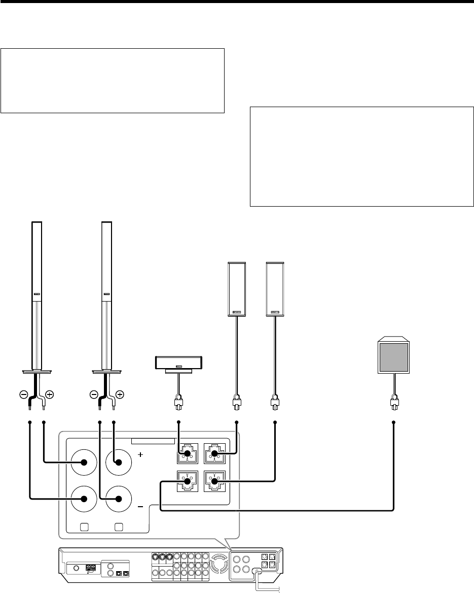
14 EN
SPEAKERS (6
-
8Ω)
R LFRONT
CENTER SURR R
SURR BACK
/SW
SURR L
For Europe and Australia
Setting up the system
Front Speakers
Surround Speakers
Be sure to connect both surround speakers
Subwoofer/ Surround Back Speaker
When the surround back speaker is connected to these
terminals, set the speaker setting to
"BS/SW BS".
In this case, the subwoofer should be connected to the
PRE OUT SUBWOOFER jack ^
Center
Speaker
LeftRight
LeftRight
Whether each speaker is connected properly can be
confirmed by outputting the test tone and checking if
each speaker channel outputs audio. For details, see
"Speaker settings" (Step 6 Adjust the speaker volume
level). §
CAUTION
Make sure that the power cord plug is disconnected from the AC
wall outlet before proceeding to speaker cord connections.
If the conductor wires on the extremity of speaker cord are
untwisted, there is a risk of short-circuiting. Be sure to twist
them well before connecting the speaker cord.
Protection circuitry
This unit incorporates protection circuitry, which may be activated
during high-power reproduction or in case of extreme rise in tempera-
ture.
When the protection circuitry is activated, the output from this unit is
shut down and the STANDBY indicator blinks.
In this case, turn this unit OFF then ON again and reduce the output
volume level.
15 EN
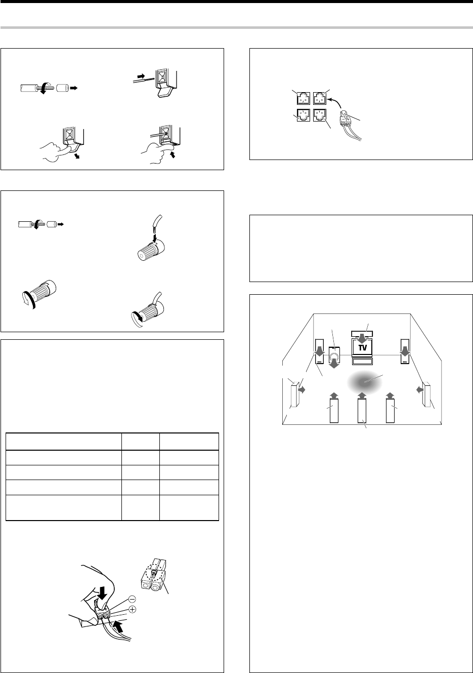
Speaker placement
Front speakers : Place the left and right speakers at each side of your TV.
Angle the speakers towards the listening area to enhance the stereo
effect.
Center speaker : Place the center speaker on the center between the
front left and right speakers. Tilt the speaker upward or down-ward so
that it is directly facing the listening area.
Surround speakers : Place the surround speakers as high as possible,
either directly to the sides of the listening area or else slightly behind
the listening area. Adjust the angles so that these speakers are facing
directly towards the listeners.
Subwoofer : Usually, place the subwoofer in the front center position in
the listening room, near one of the front speakers near the center
speaker. (Since the subwoofer has less directivity than other speakers,
it can be placed almost in any position that can offer the best low
frequency reproduction according to the room layout.)
Surround back speakers : Place the surround back speaker behind the
listining position, at the same height as the left and right surround
speakers.
¶Although the ideal surround system consists of all the speakers listed
above, if you don't have a center speaker or a subwoofer, you can
divide those signals between the available speakers in the speaker
settings steps to obtain the best possible surround reproduction from
the speakers you have available. ¢
Setting up the system
Speaker impedance
After confirming the speaker impedance indications printed on the
rear panel of the receiver, connect speakers with matching imped-
ance ratings. Using speakers with a rated impedance other than that
indicated on the rear panel of the receiver could result in malfunctions
or damage to the speakers or receiver.
¶Never short circuit the + and – speaker cords.
¶If the left and right speakers are connected inversely or the
speaker cords are connected with reversed polarity, the sound
will be unnatural with ambiguous acoustic imaging. Be sure to
connect the speakers correctly.
Connecting the speaker terminals
Connect the connector to the terminal on the receiver with the
same color by inserting the connector straight until it clicks.
1 Strip coating.
2Loosen.
3 Insert.
4 Secure.
1Strip coating.
2Push the lever.
3Insert the cord.
4Return the lever. Confirm the connector
orientation before insertion.
For U.S.A. and Canada
For Europe and Australia
Attaching the speaker cord connectors;
Connect each speaker cord by matching the color of the connector
with that of the terminal to which the speaker cord is to be
connected.
If the provided speaker cords are too short, they can be replaced
with commercially available speaker cords [AWG24-18 standard
(conductor section diameter 0.511 to 1.024 mm(0.02 to 0.04 in.))].
When using commercially available speaker cords, strip the vinyl
coating on the end of each cord by about 1 cm (0.39 in.) and twist
the conductor wires so that they are not disentangled.
While applying the projected part of the connector against a hard
desktop, etc., insert the conductor sections of the speaker cord
into the connector.
¶After attaching the speaker cord connector, hold it and pull the speaker
cord lightly to ensure that it will not come out.
CENTER
SURR R
SURR L
SURR BACK/SW
Projected part
(White)
Connector
Green
Center speaker
Grey
Surround speaker (Right)
Blue
Surround speaker (Left)
Brown
Surround back speaker
or Subwoofer
Connected speaker
Green
Brown
Grey
Blue
Center speaker
Front
speakers
Listening
position
Surround
speakers
*Surround Back
*Right speaker
*Surround Back
*Left speaker
*Surround Back speaker
Subwoofer
* For Surround Back speaker, you may place either two Surround
Back speakers (Surround Back Left speaker and Surround Back
Right speaker) for 7.1 channel surround sound system or one
Surround Back speaker for 6.1 channel surround sound system.
Connected
terminal
CENTER SURR R
SURR BACK
/SW
SURR L
Twist
Twist
*5462/08-19/EN 04.4.13, 8:01 PM15
16 EN
Setting up the system
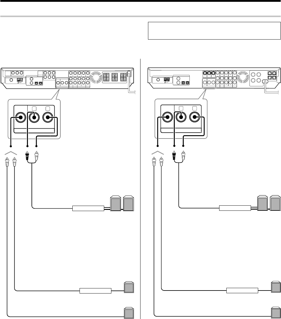
PRE OUT connections
SUB
WOOFER SURROUND BACK
RL
PRE OUT
¶Connecting a speaker cord directly to a PRE OUT jack will not
produce any sound from the speaker.
Power amplifier
Power amplifier
Powered subwoofer
Subwoofer
Surround Back speakers
For U.S.A. and Canada
SUB
WOOFER SURROUND BACK
RL
PRE OUT
For Europe and Australia
LR
Example:
¶When you want to connect two surround back
speakers.
¶When the subwoofer is connected to the
SURR BACK/SW terminals.
Example:
¶When the surround back speaker is connected to
the SURR BACK/SW terminals.
Power amplifier
Power amplifier
Powered subwoofer
Subwoofer
Surround Back speakers
LR
The receiver has additional PRE OUT jacks.
Note that the output from the PRE OUT jacks needs to be connected
to an external power amplifier.
If you want to connect surround back speakers to these jacks, be always
sure to connect two surround back speakers for the left and right.
Example:
¶When you want to connect two surround back
speakers.
¶When the subwoofer is connected to the
SURR BACK/SW terminals.
Example:
¶When the surround back speaker is connected to
the SURR BACK/SW terminals.
*5462/08-19/EN 04.4.13, 8:01 PM16
17 EN
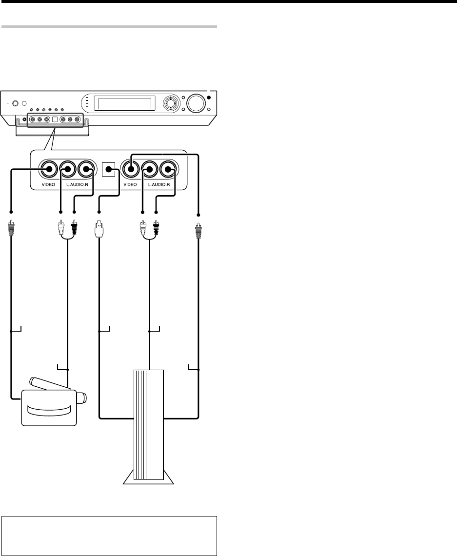
Setting up the system
Connecting to the GAME jacks / FRONT AUX jacks
If you use a component that you do not usually connect to the receiver,
such as a portable video camera, connect it to the GAME or FRONT AUX
jacks on the front panel of the receiver. These jacks are particularly
convenient when dubbing audio/video from a portable video camera.
INPUT SELECTOR
VIDEO
OUT
AUDIO
OUT
Camcorder
¶The DIGITAL IN (OPTICAL) jack in the GAME jack section can be
used for connection of digital audio input. This is convenient for
playing a video game through the receiver. ¶
OPTICAL
DIGITAL
OUT
(AUDIO)
AUDIO
OUT
VIDEO
OUT
Game Player
*5462/08-19/EN 04.4.13, 8:01 PM17
18 EN
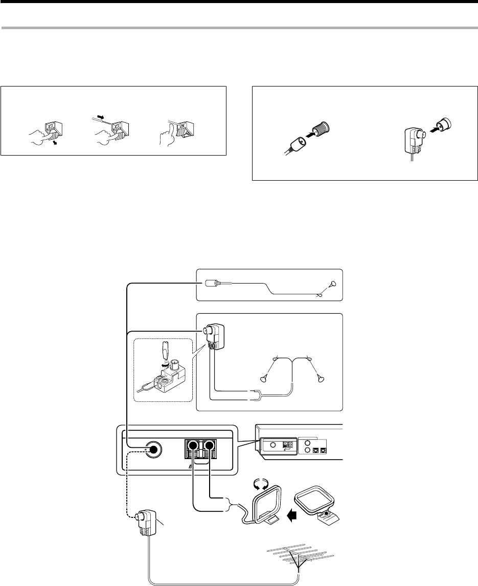
ANTENNA
AMGNDFM 75 Ω
Setting up the system
Connecting the antennas
AM loop antenna
The supplied loop antenna is for use indoors. Place it as far as possible
from the receiver, TV set, speaker cords and power cord, and adjust the
direction for best reception.
AM antenna terminal connections
1 Push lever. 2 Insert cord. 3 Release lever.
FM antenna terminal connections
Insert the connector.
FM indoor antenna
The supplied indoor antenna is for temporary use only. For stable signal
reception we recommend using an outdoor antenna. Disconnect the
indoor antenna when you connect one outdoors.
FM outdoor antenna
Lead the 75Ω coaxial cable connected to the FM outdoor antenna into the
room and connect it to the FM 75Ω terminal.
AM loop antenna
FM outdoor antenna
Use an antenna adaptor
(Commercially available)
Attach to the stand
FM indoor antenna
Black
White
FM indoor antenna
For the U.S.A. and Canada
For Europe and Australia
Antenna adaptor
(For the U.S.A. and Canada) (For Europe and Australia)
19 EN
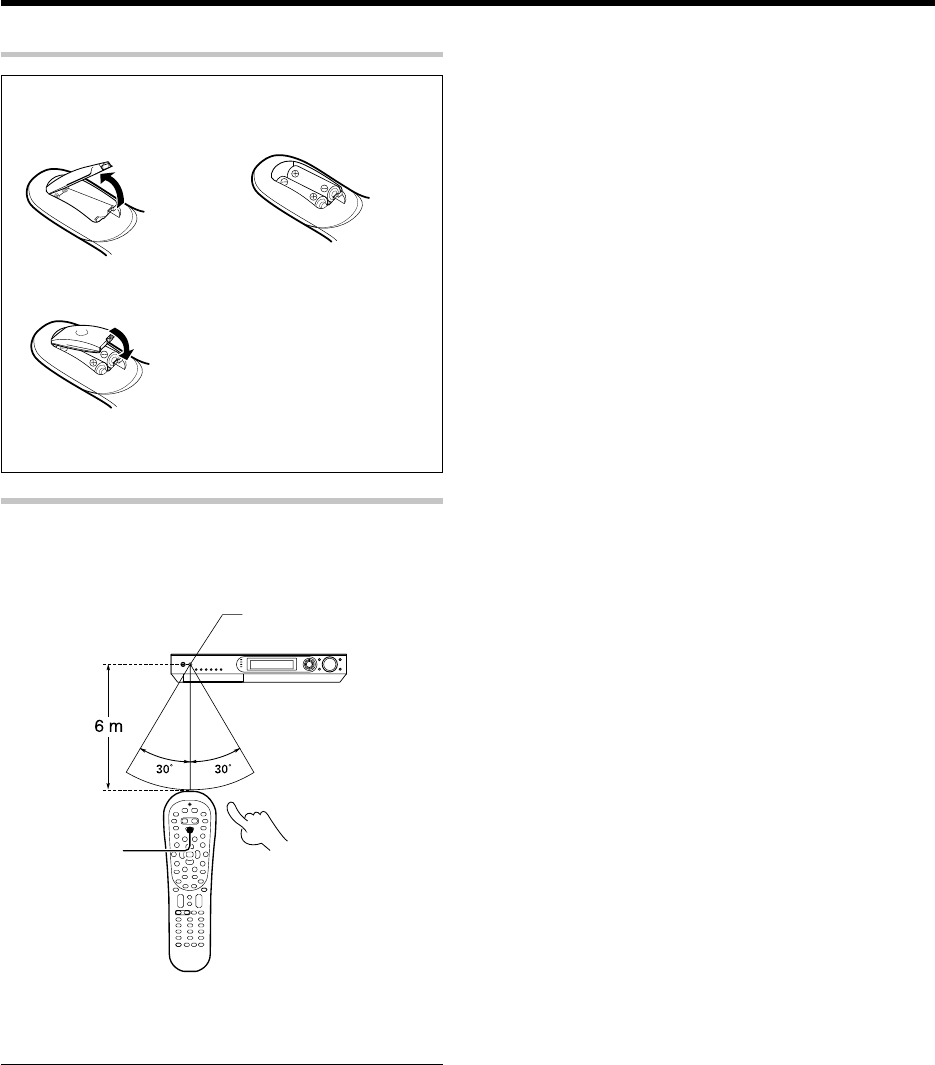
Preparing the remote control
Loading the batteries
1Remove the cover. 2 Insert the batteries.
3Close the cover.
¶Insert two AA-size (R6) batteries as indicated by the polar-
ity markings.
Remote control operation
When the STANDBY indicator is lit, the power turns ON when you press
the POWER RCVR on the remote control. When the power comes ON,
press the key you want to operate.
¶When pressing more than one remote control key successively,
press the keys securely by leaving an interval of 1 second or more
between keys.
Notes
1. The supplied batteries may have shorter lives than ordinary batteries
due to use during operation checks.
2. When the remote-controllable distance gets shorter than before,
replace both batteries with new ones.
3. Placing the remote sensor in direct sunlight, or in direct light from a
high frequency fluorescent lamp may cause a malfunction.
In such a case, change the location of the system installation to
prevent malfunction.
Operating other
component range
Remote sensor
POWER RCVR
Setting up the system
*5462/08-19/EN 04.4.13, 8:01 PM19
20 EN
Let’s play DVD video software
(For U.S.A. and Canada)
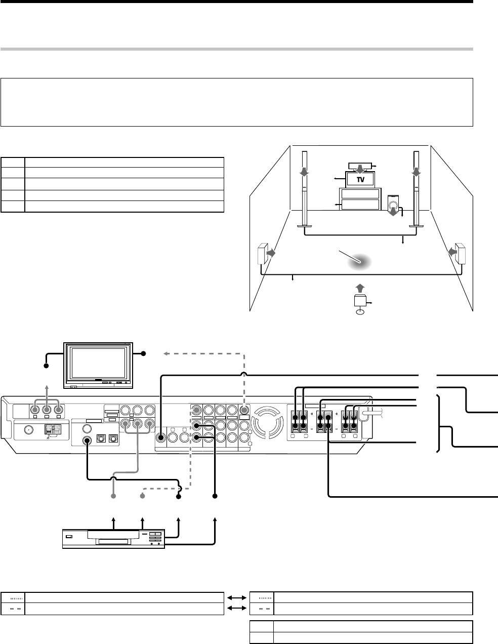
STEP 1 Connect the speakers and TV to the receiver.
Connection of TV monitor:
1Component video connection
2Composite video connection
Connection of DVD player:
1Component video connection
2Composite video connectiona
For details, see "Setting up the system"8 ~ &
Connection of speakers:
AFront speakers (L,R)
BCenter speaker
CSubwoofer
DSurround speakers (L,R)
ESurround back speaker
÷For the video input connection from the DVD player and the video
output connection to the TV monitor, use either the component video
or composite video connection for both of them.
÷If you want to connect two surround back speakers (LB and RB)
to the PRE OUT SURROUND BACK jacks, see "PRE OUT
connections". ^
SUB
WOOFER
VIDEO 2 VIDEO 1 AUXDVD
PL AY I N REC OUT P L AY I N ININ
SURROUND BACK
VIDEO
IN
VIDEO
IN
VIDEO
IN
VIDEO OUT
VIDEO
IN
MONITOR
OUT
RL L
R
PRE OUT
1A
C
B
D
E
12 3 4
2
OUTPUT
COMPONENT
VIDEO
ANTENNA
Y
Y C
B
C
R
SPEAKERS (6
-
8Ω)
RR LFRONT R LSURRCENTER
SURR BACK
/SW
AMGNDFM 75 Ω
(ASSIGNABLE)
DIGITAL IN
COAX 2
(VIDEO 2)
COAX 1
(DVD)
OPT 1
(VIDEO 1)
OPT 2
(AUX)
(
ASSIGNABLE
)
INPUT
COMPONENT
IN 2
IN 1
VIDEO
(VIDEO 2)
(DVD)
C
LS RS
BS
LR
SW
1
~
1
~
A
C
B
DVD
RECEIVER
D
E
Listening position
3Digital audio connection (Coaxial cord)
4Analog audio connection
CAUTION
Make sure that the power cord plug is disconnected from the AC wall outlet before proceeding to speaker cord connections.
If the conductor wires on the extremity of speaker cord are untwisted, there is a risk of short-circuiting. Be sure to twist them well before
connecting the speaker cord.
*5462/20-36/EN 04.4.13, 8:01 PM20
21 EN
1
Press to select "DVD".
2
Start playback of the DVD player.
For the operation, also refer to the instruction manual for your DVD player.
÷You can select various listen modes to enjoy surround playback of various kinds of video software. ‚
STEP 3 Play a disc on the DVD player.
Let’s play DVD video software (For U.S.A. and Canada)
1Connect the power cord to the AC wall outlet and press .
2Press , press to select "SP SETUP" and press .
÷When the speaker setting is set to "BS/SW OFF", the PL IIx, DTS-ES and DOLBY EX listen modes cannot be selected.
÷More detailed settings such as the volume level of each speaker and distance to each speaker are also available. §¶
If you connect KENWOOD speaker system KS-2100HT, KS-3100EX, KS-708HT, KS-308HT, KS-708HT+KS-308EX, KS-308HT+ KS-308EX, KS-908HT or KS-908EX:
Press to select the model of the connected speaker system and press .
If your selection is correct, press to select "OK" and press . Now the speaker setup is complete. (Select "CANCEL" to return to the status before setup.)
÷When the speaker setting is set to "HTB1 5.1CH", "HTB2 5.1CH" or "HTB3 5.1CH", the PL IIx, DTS-ES and DOLBY EX listen modes cannot be selected.
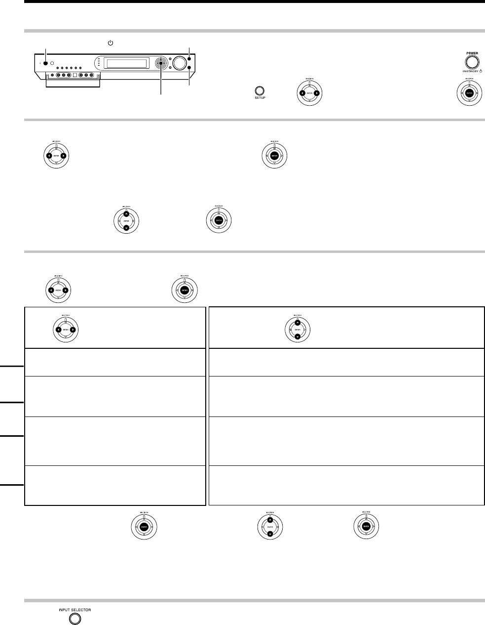
STEP 2 Set up the speakers.
If you use another speaker system want a setup according to it:
Press to select "CUSTOM" and press to select each of the speaker setup items.
After completing the setup, press .
If your selection is correct, press to select "OK" and press .
Now the speaker setup is complete. (Select "CANCEL" to return to the status before setup.)
For details, see "Speaker settings" . ¢ ~ ¶
Press to select the speaker setup item Press to select the setting for each item
SUBW ON: A subwoofer is connected.
SUBW OFF: No speaker is connected.
FRNT Speaker size ?
LRG: Relatively large-size speakers.
NML: Normal-size speakers.
CNTR, SURR, BS Speaker size ?
LRG: Relatively large-size speakers.
NML: Normal-size speakers.
OFF: No speaker is connected.
SUBW
BS/SW BS/SW BS: A surround back speaker is connected to the SURR BACK/SW terminals.
BS/SW SW: A subwoofer is connected to the SURR BACK/SW terminals.
BS/SW OFF: No speaker is connected.
SETUP
POWER ON/STANDBY
MULTI CONTROL %/fi/@/#
ENTER
INPUT SELECTOR
"HTB1 6.1CH": Speaker system KS-3100EX.
"HTB1 5.1CH": Speaker system KS-2100HT.
"HTB2 6.1CH": SPEAKER SYSTEM KS-708HT+KS-308EX or KS-
308HT+ KS-308EX.
"HTB2 5.1CH": Speaker system KS-708HT or KS-308HT.
"HTB3 6.1CH": Speaker system KS-908EX.
"HTB3 5.1CH": Speaker system KS-908HT.
Model availability may differ depending on the country and sales area.
*5462/20-36/EN 04.4.13, 8:01 PM21
22 EN
Let’s play DVD video software
(For Europe and Australia)
DVD
IN
SUB
WOOFER
VIDEO 2
IN
MONITOR
OUT
S VIDEO
VIDEO 2 VIDEO 1 AUXDVD
PLAY IN REC OUT PLAY IN ININ
SURROUND BACK
VIDEO
IN
VIDEO
IN
VIDEO
IN
VIDEO OUT
VIDEO
IN
MONITOR
OUT
SPEAKERS (6
-
8Ω)
RL L
RR LFRONT
CENTER
SURR BACK
/SW
SURR L
SURR R
PRE OUT
1
A
C
B
D
E
12 3 4
2
ANTENNA
AMGNDFM 75 Ω
(ASSIGNABLE)
DIGITAL IN
COAX 2
(VIDEO 2)
COAX 1
(DVD)
OPT 1
(VIDEO 1)
OPT 2
(AUX)
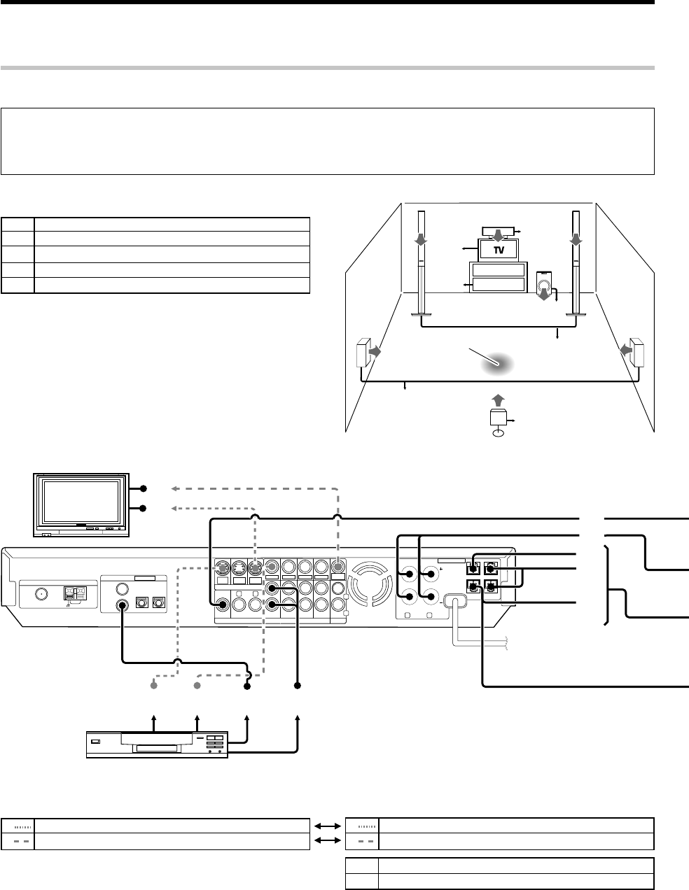
STEP 1 Connect the speakers and TV to the receiver.
For details, see "Setting up the system"8 ~ &
Connection of speakers:
AFront speakers (L,R)
BCenter speaker
CSubwoofer
DSurround speakers (L,R)
ESurround back speaker
÷If you want to connect two surround back speakers (LB and RB)
to the PRE OUT SURROUND BACK jacks, see "PRE OUT
connections".^
CAUTION
Make sure that the power cord plug is disconnected from the AC wall outlet before proceeding to speaker cord connections.
If the conductor wires on the extremity of speaker cord are untwisted, there is a risk of short-circuiting. Be sure to twist them well before
connecting the speaker cord.
Connection of TV monitor:
1S VIDEO connection
2Composite video connection
Connection of DVD player:
1S VIDEO connection
2
Composite video connection
÷For the video input connection from the DVD player and the video
output connection to the TV monitor, use either the S VIDEO or
composite video connection for both of them.
3Digital audio connection (Coaxial cord)
4Analog audio connection
C
LS RS
BS
LR
SW
1
~
1
~
A
C
B
DVD
RECEIVER
D
E
Listening position
*5462/20-36/EN 04.4.13, 8:01 PM22
23 EN
Let’s play DVD video software (For Europe and Australia)
1Connect the power cord to the AC wall outlet and press .
2Press , press to select "SP SETUP" and press .
STEP 2 Set up the speakers.
For details, see "Speaker settings" . ¢ ~ ¶
SETUP
ON/STANDBY
MULTI CONTROL %/fi/@/#
ENTER
INPUT SELECTOR
1
Press to select "DVD".
2
Start playback of the DVD player.
For the operation, also refer to the instruction manual for your DVD player.
÷You can select various listen modes to enjoy surround playback of various kinds of video software. ‚
STEP 3 Play a disc on the DVD player.
÷When the speaker setting is set to "BS/SW OFF", the PL IIx, DTS-ES and DOLBY EX listen modes cannot be selected.
÷More detailed settings such as the volume level of each speaker and distance to each speaker are also available. §¶
If you connect KENWOOD speaker system KS-2100HT, KS-3100EX, KS-708HT, KS-308HT, KS-708HT+KS-308EX, KS-308HT+ KS-308EX, KS-908HT or KS-908EX:
Press to select the model of the connected speaker system and press .
If your selection is correct, press to select "OK" and press . Now the speaker setup is complete. (Select "CANCEL" to return to the status before setup.)
÷When the speaker setting is set to "HTB1 5.1CH", "HTB2 5.1CH" or "HTB3 5.1CH", the PL IIx, DTS-ES and DOLBY EX listen modes cannot be selected.
If you use another speaker system want a setup according to it:
Press to select "CUSTOM" and press to select each of the speaker setup items.
After completing the setup, press .
If your selection is correct, press to select "OK" and press .
Now the speaker setup is complete. (Select "CANCEL" to return to the status before setup.)
Press to select the speaker setup item Press to select the setting for each item
SUBW ON: A subwoofer is connected.
SUBW OFF: No speaker is connected.
FRNT Speaker size ?
LRG: Relatively large-size speakers.
NML: Normal-size speakers.
CNTR, SURR, BS Speaker size ?
LRG: Relatively large-size speakers.
NML: Normal-size speakers.
OFF: No speaker is connected.
SUBW
BS/SW BS/SW BS: A surround back speaker is connected to the SURR BACK/SW terminals.
BS/SW SW: A subwoofer is connected to the SURR BACK/SW terminals.
BS/SW OFF: No speaker is connected.
"HTB1 6.1CH": Speaker system KS-3100EX.
"HTB1 5.1CH": Speaker system KS-2100HT.
"HTB2 6.1CH": SPEAKER SYSTEM KS-708HT+KS-308EX or KS-
308HT+ KS-308EX.
"HTB2 5.1CH": Speaker system KS-708HT or KS-308HT.
"HTB3 6.1CH": Speaker system KS-908EX.
"HTB3 5.1CH": Speaker system KS-908HT.
Model availability may differ depending on the country and sales area.
*5462/20-36/EN 04.4.13, 8:01 PM23
24 EN
Preparing for playback
SETUP
ON/STANDBY
POWER ON/STANDBY
MULTI CONTROL %/fi/@/#
Setup
POWER RCVR
RCV Mode
Multi %/fi/@/#
ENTER
Enter
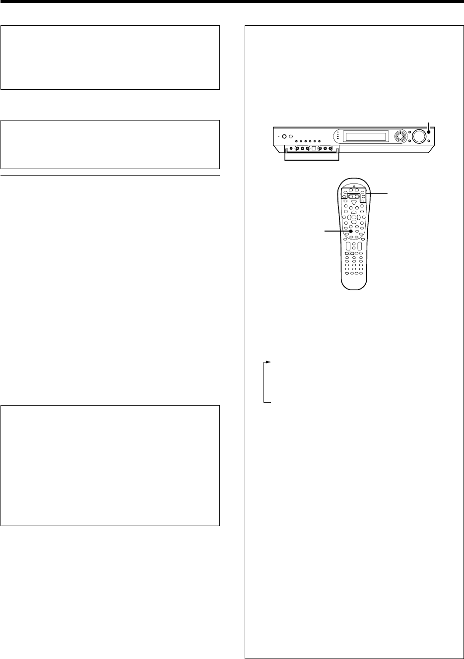
Speaker settings
To enable you to obtain optimum enjoyment from the receiver’s listening
modes, make sure to complete the speaker settings (subwoofer, front,
center, surround and surround back speakers) as described below.
1
Turn on the power to this receiver by pressing the POWER ON/
STANDBY (For U.S.A. and Canada) or ON/STANDBY (For
Europe and Australia) key (or POWER RCVR key).
2
If you want to use the remote control unit, press the RCV Mode
key on the remote to set it to the receiver control mode.
3
Initiate the setup mode.
1Press the SETUP key (or the Setup key).
2Use the MULTI CONTROL @ / # (or the Multi @ / # keys)
for the following displays.
1"SP SETUP"
2"SP LEVEL"
3"DISTANCE"
4"ASSIGN."
5"LFE LEVEL"
6"GAME FUNC"
7"EXIT"
÷While the main setup screen is displayed, the setup mode
can be canceled by pressing the SETUP key (or the Setup
key) or selecting "EXIT" and then pressing the ENTER (or the
Enter key).
4
Select the setup method.
1Select "SP SETUP" and press the ENTER key (or the
Enter key) to select the speaker setup method.
2Use the MULTI CONTROL @ / # (or the Multi @ / # keys)
for the following displays.
1"HTB1 6.1CH": Select "HTB1 6.1CH" if you use speaker
system KS-3100EX. *
2"HTB1 5.1CH": Select "HTB1 5.1CH" if you use speaker
system KS-2100HT. *
3"HTB2 6.1CH": Select "HTB2 6.1CH" if you use speaker
system KS-708HT+KS-308EX or KS-308HT+KS-308EX. *
4"HTB2 5.1CH": Select "HTB2 5.1CH" if you use speaker
system KS-708HT or KS-308HT. *
5"HTB3 6.1CH": Select "HTB3 6.1CH" if you use speaker
system KS-908EX. *
6"HTB3 5.1CH": Select "HTB3 5.1CH" if you use speaker
system KS-908HT.*
7"CUSTOM": Select to set up the speakers according to
the speaker system in use. (Speaker setup is required
every time after the speaker system is changed.)
8"EXIT": Press the ENTER (or the Enter key) again to
return to the main setup displays.
*Model availability may differ depending on the country
and sales area.
÷When the 5.1 channel speaker system configuration is used
or the speaker setting is set to "BS/SW OFF", the PL IIx, DTS-
ES and DOLBY EX listen modes cannot be selected.
If you selected "HTB1 6.1CH", "HTB1 5.1CH", "HTB2 6.1CH",
"HTB2 5.1CH", "HTB3 6.1CH" or "HTB3 5.1CH" in the above:
Press ENTER (or the Enter key), then press MULTI CONTROL
% / fi (or the Multi % / fi keys) to select "OK", and press ENTER
(or the Enter key) again to establish the setup.
÷Select "CANCEL" to return to the status before setup.
÷When you use a KENWOOD speaker system and select
"HTB1 6.1CH", "HTB1 5.1CH", "HTB2 6.1CH", "HTB2 5.1CH",
"HTB3 6.1CH" or "HTB3 5.1CH" set the speaker setup, the
audio will be corrected automatically according to the
speaker characteristics.
If you selected "CUSTOM" in the above:
Press ENTER (or the Enter key) to proceed to detailed setups.
The flow of the SETUP is as follows;
SP SETUP SP LEVEL DISTANCE ASSIGN.
EXIT
LEF LEVEL
GAME FUNC
Front Left
Center
Front Right
Front Left
Right Surround
Surround Back
(Right/Left
Surround Back)
Subwoofer
HTB 1 6.1CH
HTB 1 5.1CH
HTB 2 6.1CH
HTB 2 5.1CH
HTB 3 6.1CH
HTB 3 5.1CH
CUSTOM
EXIT
Subwoofer
Front
Center
Surround
Surround
Back
MANUAL/OFF
AUTO
L
C
R
SR
SL
BS
(RB/LB)
SW
L
C
R
SR
B
S
(RB/LB)
SL
SW
Digital
EXIT
D4 Video
METERS
EXIT
FEET
MODE 1
MODE 2
OFF
BS/SW
amp
Subwoofer
Re-mix
EXIT
÷The subwoofer setting indication "SUBW" appears.
sUBW 0N
Continued to next page
*5462/20-36/EN 04.4.13, 8:01 PM24
25 EN
Preparing for playback
Continued to next page
5
Select a speaker system.
1Use the MULTI CONTROL % / fi (or the Multi % / fi keys)
to select the appropriate subwoofer setting.
1"SUBW ON" :
When a subwoofer is connected.
2"SUBW OFF" :
When no subwoofer is connected.
÷The initial setting is "SUBW ON".
÷When "SUBW OFF" is selected and the selection is established
by pressing MULTI CONTROL # (or the Multi # key) in step 2
below, the front speakers are set automatically to "FRNT LRG"
and the procedure jumps to step 5.
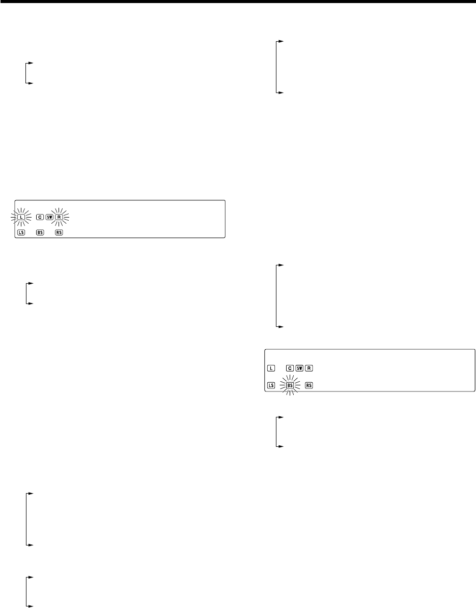
2Use the MULTI CONTROL # (or the Multi # key)
to accept the setting.
÷The front speakers setting indication "FRNT" appears.
FRNT LRG
3Use the MULTI CONTROL % / fi (or the Multi % / fi keys)
to select the appropriate front speakers setting.
1"FRNT LRG" :
Large front speakers are connected to the receiver.
2"FRNT NML" :
Average size front speakers are connected to the
receiver.
÷When the subwoofer setting is "SUBW ON", front speak-
ers setting is "FRNT LRG" and a stereo source is played,
the low frequencies may be reproduced through the
front speakers and no audio output fro the subwoofer in
certain listen modes. In this case, set the subwoofer re-
mix setting in step # to "REMIX ON" to output the low
frequencies from the subwoofer.
4Use the MULTI CONTROL # (or the Multi # key)
to accept the setting.
÷The center speaker setting indication "CNTR" appears.
5Use the MULTI CONTROL % / fi (or the Multi % / fi keys)
to select the appropriate center speaker setting.
If you selected "FRNT LRG" as the front speakers setting:
1"CNTR LRG" :
A large center speaker is connected to the receiver.
2"CNTR NML" :
An average size center speaker is connected to the
receiver.
3"CNTR OFF" :
When no center speaker is connected.
If you selected "FRNT NML" as the front speakers setting:
1"CNTR NML" :
Average size front speakers are connected to the
receiver.
2"CNTR OFF" :
When no center speaker is connected.
6Use the MULTI CONTROL # (or the Multi # key)
to accept the setting.
÷The surround speaker setting indication "SURR" appears.
7Use the MULTI CONTROL % / fi (or the Multi % / fi keys)
to select the appropriate surround speaker setting.
1"SURR LRG" :
Large surround speakers are connected to the receiver.
2"SURR NML" :
Average size surround speakers are connected to the
receiver.
3"SURR OFF" :
When no surround speakers are connected.
÷When "SURR OFF" is selected and the selection is estab-
lished by pressing MULTI CONTROL # in step 8 below, the
procedure jumps to step #. However, if the subwoofer
setting is "SUBW OFF", the procedure jumps to step $ so
that you can complete the speaker setup and proceed to the
speaker volume level adjustment in step 6.
8Use the MULTI CONTROL # (or Multi # key) to ac-
cept the setting.
÷The surround back speaker setting indication "BS" appears.
9Use the MULTI CONTROL % / fi (or the Multi % / fi keys)
to select appropriate surround back speaker setting.
If you selected "SURR LRG" as the surround speaker setting :
1"BS LRG" :
Large surround back speaker is connected to the re-
ceiver.
2"BS NML" :
Average size surround back speaker is connected to the
receiver.
3"BS OFF" :
When no surround back speakers is connected.
Bs LRG
If you selected "SURR NML" as the surround speaker setting :
1"BS NML" :
Average size surround back speaker is connected to the
receiver.
2"BS OFF" :
When no surround back speakers is connected.
0Use the MULTI CONTROL # (or the Multi # key)
to accept the setting.
÷The surround back speaker and subwoofer setting mode
indication "BS/SW" appears.
*5462/20-36/EN 04.4.13, 8:01 PM25
26 EN
Preparing for playback
!Use the MULTI CONTROL % / fi (or the Multi % / fi keys)
to select the appropriate BS/SW amp setting.
1"BS/SW BS":
Select this setting when a surround back speaker is
connected to the SURR BACK/SW terminals. In this
case, the subwoofer signal will be output from the PRE
OUT SUBWOOFER jack.
2 "BS/SW SW":
Select when the subwoofer speaker is connected to the
SURR BACK/SW terminals. In this case, the surround
back signals will be output from the PRE OUT SUR-
ROUND BACK jacks.
3 "BS/SW OFF":
Select when no speaker is connected to the SURR
BACK/SW terminals. In this case, the subwoofer signal
will be output from the PRE OUT SUBWOOFER jack and
the surround back signals will be output from the PRE
OUT SURROUND BACK jacks.
÷If "BS/SW BS" is selected, only one surround back
speaker can be connected to the receiver.
÷If "BS/SW SW" or "BS/SW OFF" is selected, two sur-
round back speakers can be connected to the PRE OUT
SURROUND BACK jacks through an external power
amplifier. ^
@Use the MULTI CONTROL # (or the Multi # key)
to accept the setting.
÷The subwoofer re-mix setting indication "REMIX" appears.
#Use the MULTI CONTROL % / fi (or the Multi % / fi keys)
to select the appropriate subwoofer re-mix setting.
If "REMIX ON" is selected as the subwoofer re-mix setting,
the low frequencies are enhanced by adding the low fre-
quencies of other channels to the subwoofer channel or
adding the low frequencies of the subwoofer to other
channels depending on the speaker setup.
1"REMIX ON" :
Subwoofer re-mix setting mode to the receiver is ON.
2"REMIX OFF" :
Subwoofer re-mix setting mode to the receiver is OFF.
÷The initial setting is "REMIX ON".
÷The subwoofer re-mix setting is possible only when the
subwoofer setting is "SUBW ON" and the front speaker
setting is "FRNT LRG".
$Press ENTER (or the Enter key). If your selection is
correct, press MULTI CONTROL % / fi (or the Multi
% / fi key) to select "OK".
Press the ENTER (or the Enter key) again to return to
the main setup displays.
÷Select "CANCEL" and press the ENTER (or the Enter
key) to return to the status before setup.
÷In steps 6 and 7, indications appear only for the se-
lected channels of the speakers that require adjusting.
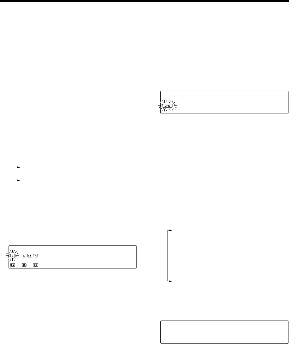
6
Adjust the speaker volume level.
From your usual listening position, adjust the volume levels. The volume
levels from each speaker should be the same.
1Use the MULTI CONTROL @ / # (or the Multi @ / # keys)
to select "SP LEVEL" on setup displays, and press the
ENTER (or the Enter key).
2Use the MULTI CONTROL @ / # (or the Multi @ / # keys)
to select "AUTO", "MANUAL" or "OFF".
1"AUTO": Select this setting to adjust the speaker volume
levels using the test tone. The test tone will be output from
every speaker channel in automatic sequence.
2"MANUAL": Select to select the speaker channel to
output the test tone using MULTI CONTROL@ / #
(or the Multi @ / # key).
3"OFF": Select to adjust the speaker volume levels
using the current output signals. The speaker chan-
nel to output the output signal can be selected using
MULTI CONTROL@ / # (or the Multi @ / # key).
4"EXIT": Press the ENTER (or the Enter key) again to
return to the main setup displays.
When "AUTO" or "MANUAL" is selected and ENTER (or the
Enter key) is pressed again, the test tone output will start.
Use the MULTI CONTROL % / fi (or the Multi % / fi keys)
to adjust the volume level of the test tone output from
the speaker channel to be adjusted.
For
"
AUTO
"
selection, the first test tone is heard from
the front left speaker for 2 seconds. The next test tone
is heard from the speakers in the following sequence
for 2 seconds each.
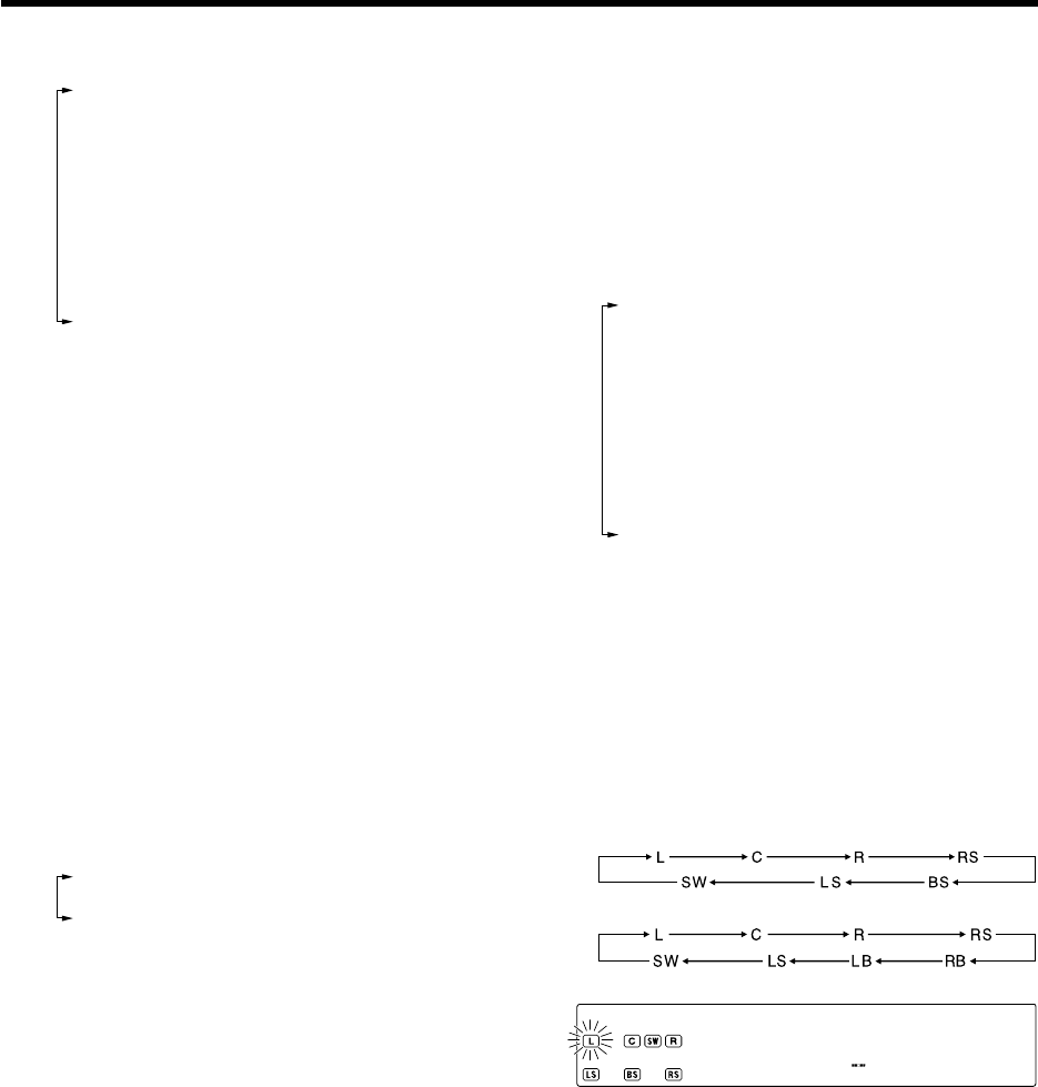
When the "BS/SW BS" has been selected :
When the "BS/SW SW" or "BS/SW OFF" has been selected:
The channel indication blinks while the test tone is being output.
L 1 ) dB
÷If you change the volume level settings for the speakers while
listening to music, the settings referred to on this page are
also changed. w
÷If the speaker setting selects are OFF, the speaker level
settings are reset.
When "MANUAL" or "OFF" is selected, press MULTI
CONTROL @/# (or the Multi @/# key) to select the
speaker channel and then press MULTI CONTROL %/fi
(or the Multi %/fi key) to adjust the speaker volume level.
3Press the ENTER (or the Enter key) again to return to
the main setup displays.
÷The test tone is turned off and return to the main setup
displays.
*5462/20-36/EN 04.4.13, 8:01 PM26
27 EN
Preparing for playback
7
Input the distance to the speakers.
This setting allows the signals output from different speakers to reach
the listening position simultaneously.
Measure the distance from the listening position to each
of the speakers.
Jot down the distance to each of the speakers.
Distance to Front speaker (L) : ____ feet (meters)
Distance to Center speaker (C) : ____ feet (meters)
Distance to Front speaker (R) : ____ feet (meters)
Distance to Surround speaker (RS) : ____ feet (meters)
Distance to Surround back speaker (RB) : ____ feet (meters)
Distance to Surround back speaker (LB) : ____ feet (meters)
Distance to Surround speaker (LS) : ____ feet (meters)
Distance to Subwoofer (SW) : ____ feet (meters)
1Use the MULTI CONTROL @ / # (or the Multi @ / # keys)
to select "DISTANCE" on setup displays, and press the
ENTER (or the Enter key).
2Use the MULTI CONTROL @ / # (or the Multi @ / # key)
to select the unit and press ENTER (or the Enter key).
1"METERS"
2"FEET"
3"EXIT": Press the ENTER (or the Enter key) again to
return to the main setup displays.
3Use the MULTI CONTROL @ / # (or the Multi @ / # keys)
to select the speakers and the MULTI CONTROL % / fi
(or the Multi % / fi keys) to adjust the distance to the
front speakers.
The speaker indicator to be adjusted blinks.
÷The speakers you have selected should appear on the display.
Confirm that all the speakers have been correctly selected.
L 3)M
÷The allowable setting range is 1 to 30 feet (0.3 to 9.0 m),
adjustable in 1 foot (0.3 m) increments.
4Repeat steps 3 to input the distance for each of the
speakers.
5Press the ENTER (or the Enter key) again to return to
the main setup displays.
Indication in meters
8
Adjust the LFE LEVEL (Low Frequency Effects level)
Adjust the level of the low-frequency fields effect (LFE) signal, which is
the signal used exclusively for giving the field effect of bass tone, in the
Dolby Digital or DTS signal.
1Use the MULTI CONTROL @ / # (or Multi @ / # keys)
to select "LFE LEVEL" on setup displays, and press the
ENTER (or the Enter key).
2Use the MULTI CONTROL % / fi (or Multi % / fi keys)
to adjust the LFE LEVEL.
LF ) dEB
÷The LFE LEVEL is adjusted from 0dB to -10dB in 1dB
step decrements.
3Press the ENTER (or the Enter key) again to return to
the main setup displays.
9
Set up the GAME jacks on the front panel.
Perform the setup for convenience of playing a video game using the
receiver.
1Use the MULTI CONTROL @ / # (or Multi @ / # keys)
to select "GAME FUNC" on setup displays, and press
the ENTER (or the Enter key).
2Press MULTI CONTROL % / fi (or the Multi % / fi key)
to select the game mode.
1"MODE 1" :
When the connected game machine is turned ON, the input
selector is switched automatically to "GAME". In addition,
the ACTIVE EQ function is switched to "EQ GAME" and the
listen mode is switched to the appropriate mode for games.
2"MODE 2" :
When the connected game machine is turned ON, the input
selector is switched automatically to "GAME".
3"OFF" :
The game mode is switched OFF.
÷The game mode is not activated if no video signal is input to
the VIDEO jack in the GAME jack section.
÷The game mode is not activated when the DUAL SOURCE
function is switched ON. º
MO 1DE
3Press the ENTER (or the Enter key) again to return to
the main setup displays.
*5462/20-36/EN 04.4.13, 8:01 PM27
28 EN
Preparing for playback
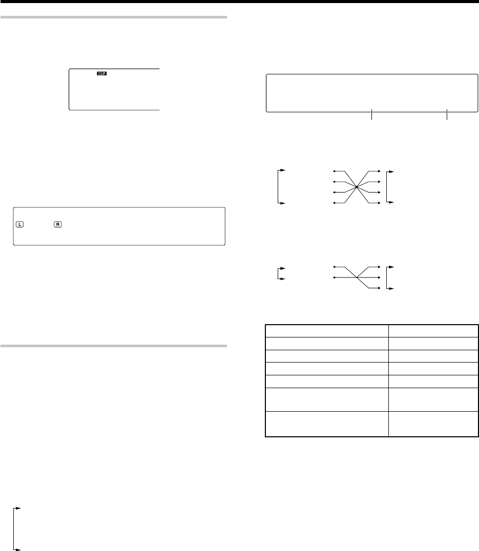
Input level adjustment (analog sources only)
If the input level of an analog source signal is too high, the "CLIP" indicator
will lights up to indicate the source signal. Adjust the input level.
1Press the RCV Mode key on the remote control unit to set
it to the receiver control mode.
2Press the Sound key.
3Use the MULTI CONTROL @ / # (or the Multi @ / # keys) to
select "INPUT", and press the ENTER (or the Enter key).
4Use the MULTI CONTROL % / fi (or the Multi % / fi keys)
to adjust the input level.
IN ) d TUPB
÷The adjustment mode is displayed for approximately 20
seconds.
÷The input level may be adjusted to any one of three settings:
0dB, -3dB, and -6dB. (The initial setting is 0dB.)
÷You can store a separate input level for each input selector.
5Press the Sound key again to return to the input indication.
Re-assignment of rear panel jacks
The assignment of the input selector positions to the digital audio and
component video input jacks can be changed as desired.
1Press the SETUP key (or the Setup key).
2Use the MULTI CONTROL @ / # (or the Multi @ / # keys)
to select "ASSIGN." on setup displays, and press the
ENTER (or the Enter key).
3Use the MULTI CONTROL @ / # (or Multi @ / # keys) to
select "DIGITAL" or "COMPONENT VIDEO", and press
the ENTER (or the Enter key).
1"DIGITAL": Select to change the assignment of the digital
audio input jacks of the receiver.
2"COMPONENT VIDEO"*: Select to change the assignment
of the component video input jacks of the receiver.
3"EXIT": Press the ENTER (or the Enter key) again to
return to the main setup displays.
* For U.S.A. and Canada only.
Input selector position (%/fi)
1"DVD"
2"V2"
3"V1"
4"AUX"
When the "DIGITAL" has been selected :
Input selector position (%/fi)
1"DVD"
2"V2"
3"V1"
Input jack selection (@/#)
1"CPNT1"
2"CPNT2"
When the "COMPONENT" has been selected :
(For U.S.A. and Canada only)
Jack name
COAX2 (VIDEO 2)
OPT1 (VIDEO 1)
OPT2 (AUX)
COMPONENT VIDEO INPUT
IN1 (DVD)
COMPONENT VIDEO INPUT
IN2 (VIDEO 2)
COAX1 (DVD)
4Press MULTI CONTROL @/# (or the Multi @/# key) to select
the input jack name and then press MULTI CONTROL % /fi
(or the Multi % /fi key) to select the input selector position.
CO D V1XAD
÷It is not permitted to assign two input selector positions for
one input jack. In this case, you will have to assign different
input selector positions again.
5Repeat step 4 until you have assigned the desired jacks
to the desired input selector positions.
6Press the ENTER (or the Enter key) again to return to the
main setup displays.
Use the following table for your memorandum.
Input jack Input selector
Assigned input selector
Input jack selection (@/#)
1"COAX1"
2"COAX2"
3"OPT1"
4"OPT2"
*5462/20-36/EN 04.4.13, 8:01 PM28
29 EN
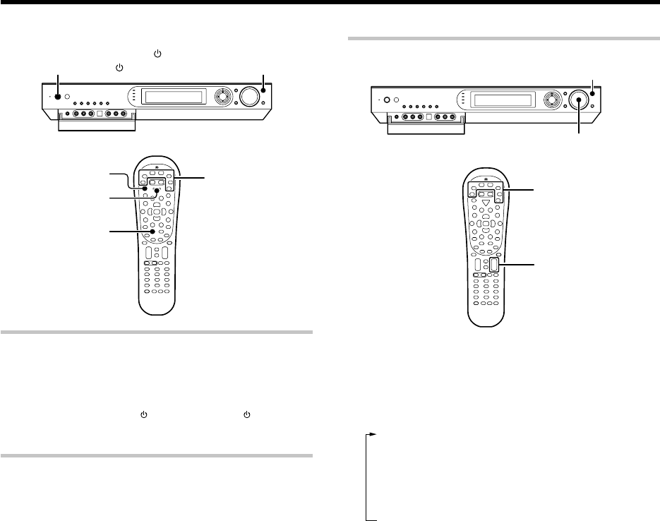
Some preparatory steps are needed before starting playback.
Turning on the receiver
1Turn on the power to the related components.
2Turn on the power to this receiver by pressing the
POWER ON/STANDBY or ON/STANDBY key (or the
POWER RCVR key).
Selecting the input mode
If you have selected a component connected to the COAX 1 (DVD),
COAX 2 (VIDEO 1), OPT 1 (VIDEO 2), OPT 2 (AUX) or DIGITAL IN
(OPTICAL) jacks, make sure that the input mode setting is correct for the
type of audio signal to be used. 8
Normal playback
ON/STANDBY
POWER ON/STANDBY
POWER RCVR
Input Mode
RCV Mode
INPUT SELECTOR
VOL + /
-
VOLUME CONTROL
INPUT SELECTOR
Input selector keys
Input selector keys
Listening to a source component
1
Press the INPUT SELECTOR key (or the Input selector
keys/ DVD, VID1, VID2, AUX, F.AUX, Game, TUNER) to
select the source you want to listen to.
1Tuner (FM/AM broadcast reception)
2"DVD"
3"VIDEO1"
4"VIDEO2"
5"GAME"
6"FRONT AUX"
7"AUX"
2
Start playback from the selected source.
3
Use the VOLUME CONTROL knob (or the VOL +/- keys) to
adjust the volume.
*5462/20-36/EN 04.4.13, 8:01 PM29
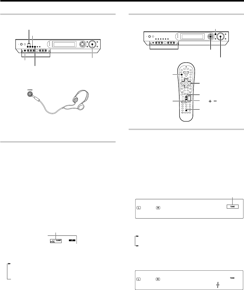
30 EN
Listening with headphones
PHONES
DUAL SOURCE VOLUME 5/∞
DUAL SOURCE INPUT
DUAL SOURCE ON/OFF
VOLUME CONTROL
1Connect headphones to the PHONES jack.
2Use the VOLUME CONTROL knob (or the VOL +/– keys)
to adjust the volume.
Playing difference sources through speakers and
headphones (DUAL SOURCE function)
While you enjoy audio listening through the speakers, another person
can enjoy another source (audio + video) through headphones by
connecting the source to the GAME or FRONT AUX jacks.
1Connect headphones to the PHONES jack.
2Press the DUAL SOURCE ON/OFF key to switch the DUAL
SOURCE function ON.
÷When the DUAL SOURCE function is ON, the video and head-
phone outputs reproduce only the second input source of the
DUAL SOURCE function. Switching the DUAL SOURCE function
OFF restores the main input source signals at these outputs.
3Press the DUAL SOURCE INPUT key to select the second
input source for the DUAL SOURCE function.
1"GAME" :
The "GAME" input is selected as the second input source for
the DUAL SOURCE function.
2"F. AUX" :
The "F. AUX" input is selected as the second input source for
the DUAL SOURCE function.
4Press the DUAL SOURCE VOLUME 5 / ∞ to adjust the
headphone listening volume.
÷When the DUAL SOURCE function is switched ON, the input
mode is fixed at "ANALOG". The listen mode cannot be
changed. 8‚
Lights up
Normal playback
Adjusting the sound
VOLUME CONTROL
VOL /
MULTI CONTROL %/fi/@/#
ENTER
ACTIVE EQ
RCV Mode
Sound
Multi %/fi/@/#
Mute
Active EQ
Enter
Adjusting the TONE
(PCM stereo and analog stereo mode only)
1Press the RCV Mode key on the remote control unit to set
it to the receiver control mode.
2Press the Sound key.
3Use the MULTI CONTROL @ / # (or the Multi @ / # keys)
to select "TONE", and press the ENTER (or the Enter key).
4Use the MULTI CONTROL % / fi (or the Multi % / fi keys) to
select "TONE ON", and pressthe ENTER (or the Enter key).
TO O ENN
5Use the MULTI CONTROL @ / # (or the Multi @ / #
keys) to select "BASS" or "TREBLE".
1"BASS" :
Select this to adjust the low frequency range.
2"TREBLE" :
Select this to adjust the high frequency range.
6Use the MULTI CONTROL % / fi (or the Multi % / fi keys)
to adjust the sound quality.
TR 1ELBE)
7Repeat steps 5 and 6 as required.
÷The bass and treble levels are adjustable from -10 to +10 in
2 step increments.
÷The adjustment item is displayed for approximately 20 sec-
onds.
8Press the Sound key again to return to the input indication.
Lights up
*5462/20-36/EN 04.4.13, 8:01 PM30
31 EN
Normal playback
ACTIVE EQ mode
You can enjoy a more impressive sound effect when ACTIVE EQ is
turned ON.
Press the ACTIVE EQ key (or the Active EQ key) for the following
selections:
1"EQ MUSIC" : (The "ACTIVE EQ" indicator lights up)
Effective when listening to music.
2"EQ CINEMA" : (The "ACTIVE EQ" indicator lights up)
Effective when watching a movie.
3"EQ GAME" : (The "ACTIVE EQ" indicator lights up)
Effective when playing a game.
4"EQ OFF" : (The "ACTIVE EQ" indicator goes off)
The ACTIVE EQ function is turned OFF.
÷The ACTIVE EQ function is not available in when the REC
MODE or virtual mode is ON.
Muting the sound
The Mute key lets you mute the sound of the speakers or headphones.
Press the Mute key.
To cancel
Press the Mute key again so that the "MUTE" indicator
goes off.
÷MUTE ON can also be deactivated by turning the VOLUME
CONTROL knob or pressing the VOL +/– keys.
Blinks
*5462/20-36/EN 04.4.13, 8:01 PM31
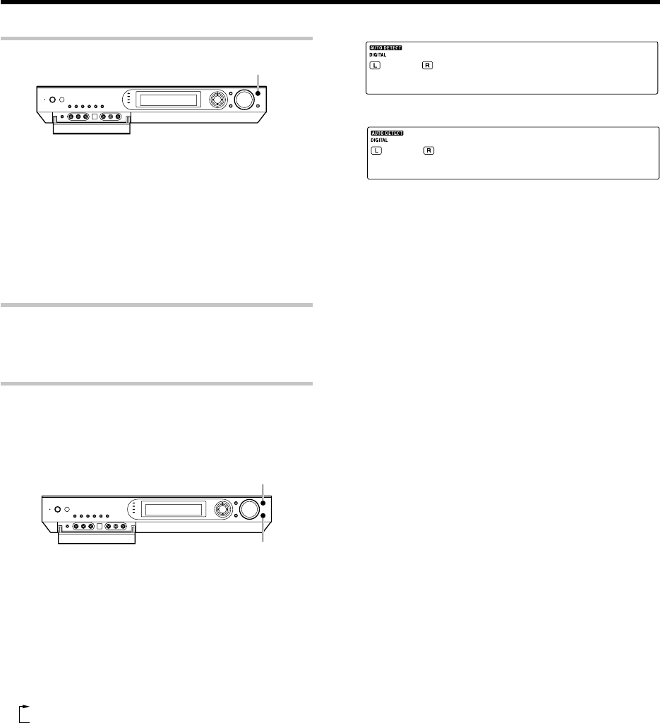
32 EN
Recording
Analog sources
1Use the INPUT SELECTOR key (or the input selector key)
to select the source (other than "VIDEO 1") you want to
record.
2Put the component connected to the VIDEO 1 jacks to the
record-pause mode.
3Start playback, then start recording.
÷Recording may not be normal for some video software. This
is due to the copy guard condition. P
Digital sources
Switch on the REC MODE to record a digital input source.
When the digital mode changes during recording in the REC MODE, the
audio signal may be interrupted momentarily.
Recording music in REC mode
When a multi-channel source such as the Dolby Digital or DTS input signal is
recorded in REC mode, the signal in the current surround mode can be recorded
down-mixed to 2-channel.
INPUT SELECTOR
SETUP
1Use the INPUT SELECTOR key (or the Input Selector
keys) to select the source (DVD, VIDEO 2, AUX, GAME)
you want to record.
2Put the component connected to the VIDEO 1 jacks to the
record-pause mode.
3Press and hold the SETUP key (or Setup key) for more
than 2 seconds to select the "REC MODE".
1 REC mode off
2 "REC MODE": REC mode on
Multi-channel digital signals (DTS or Dolby
Digital) are down-mixed to 2-channel
before being output from the analog
recording (REC OUT) jacks.
INPUT SELECTOR
RMCDOEE
↓
VR2OEDI
The display switches automatically.
4Start playback, then start recording.
*5462/20-36/EN 04.4.13, 8:01 PM32
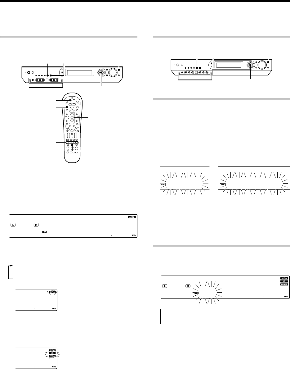
33 EN
Listening to radio broadcasts
AUTO/MONOBAND
INPUT SELECTOR
Auto 7
Tune –
1
/ +
¡
Band
RCV Mode
TUNER
Multi %/fi
MULTI CONTROL %/fi
ENTER
Tuning (non-RDS) radio stations
8)8)
The receiver can store up to 40 stations in the memory and recall them by one-touch operation.Radio stations can be classified into RDS (Radio Data System)
stations and other stations. To listen to or store RDS stations in the preset memory see "Using RDS (Radio Data System) (For Europe)". fi
1
Use the INPUT SELECTOR key (or the TUNER key) to select
the tuner.
2
Use the BAND key (or the Band key) to select the desired
broadcast band.
Each press switches the band.
-- 8 )8 )
3
Use the AUTO/MONO key (or the Auto
7
key) to select the
desired tuning method.
Each press switches the tuning method to either auto or manual tuning.
1Auto tuning:
The "AUTO" indicator lights up
2Manual tuning:
The "AUTO" indicator goes off
÷
Normally, set to "AUTO" (auto tuning). If the radio waves are weak
and there is a lot of interference, switch to manual tuning. (With
manual tuning, stereo broadcasts will be received in monaural.)
4
Use the MULTI CONTROL
%
/
fi
(or Multi
%
/
fi
keys, Tune +/
- keys) to select the station.
Auto tuning:
The next station is tuned automatically.
Manual tuning:
Use the MULTI CONTROL % / fi (or Multi % / fi ) to select the
desired station.
Presetting radio stations
AUTO/MONOBAND
INPUT SELECTOR
MULTI CONTROL %/fi
ENTER
Collective presetting of stations
(For U.S.A., Canada and Australia)
1
Use the INPUT SELECTOR key (or the TUNER key) to select
the tuner.
2
Use the BAND key (or the Band key) to select he broadcast
band to "FM".
3
Press and hold the ENTER for more than 2 seconds.
AU OT
PR TESE
The blinking "AUTO" display and blinking "PRESET" display
appear alternately.
÷A maximum of 40 stations of the band presently being
received will be preset.
÷Use the Manual Preset function if a desired FM station
cannot be preset using the Auto Preset function or when it
is required to preset AM stations.
Presetting radio stations manually
1
Tune to the station you want to store.
2
Press the ENTER while receiving the station.
)1 7 58 5
Proceed to step 3 within 5 seconds. (If more than 5 seconds
elapse, press the ENTER again).
3
Use the MULTI CONTROL
%
/
fi
(or the Multi
%
/
fi
keys) to
select one of the station presets (1 – 40).
4
Press the ENTER again to confirm the setting.
•Repeat steps 1, 2, 3, and 4 to store as many stations as
necessary.
•If you store a station at a previously used preset, the old
station will be replaced by the new one.
"AUTO" indicator lights up in the display.
"TUNED" indicator is displayed when a
station is received."ST." indicator lights
when a broadcast is being received in
stereo.
7585
*5462/20-36/EN 04.4.13, 8:01 PM33
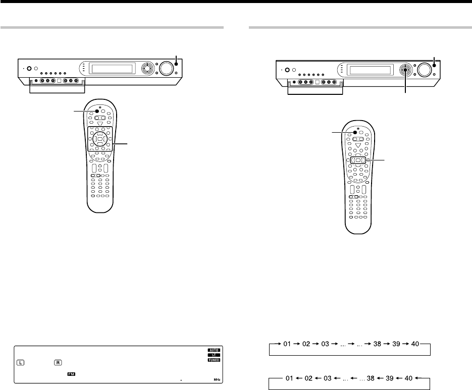
34 EN
Listening to radio broadcasts
Receiving preset stations
TUNER
INPUT SELECTOR
1
Use the INPUT SELECTOR key (or the TUNER key) to select
tune as the source.
2
Enter the number of the preset station you want to receive (up
to "40").
Press the numeric keys in the following order:
For "15", press 0,5
For "20", press 0,0,)
•If you make a mistake entering a two digit number, press the +10
key repeatedly to return to the original display and start again.
)3 7 58 5
Numeric keys
Receiving preset stations in order (P.CALL)
INPUT SELECTOR
TUNER
P.Call
@
/
#
MULTI CONTROL @
/
#
1
Use the INPUT SELECTOR key (or the TUNER key) to select
tune as the source.
2
Use the MULTI CONTROL
@
/
#
(or the P.Call
@
/
#
keys) to
select the desired station.
•Each time you push the Joystick, another preset station is
received in order.
Pushing the Joystick to # does the following:
Pushing the Joystick to @ does the following:
Holding the Joystick on # or @ direction, lets you skip through the
presets, receiving each preset station at 0.5 second intervals.
*5462/20-36/EN 04.4.13, 8:01 PM34
35 EN
Using the RDS Disp. (Display) key
TUNER
RDS Disp.
Pressing the RDS Disp. key changes the contents of the display.
Each press switches the display mode as follows :
1PS (Program Service name) display
2RT (Radio Text) display
3Frequency display
1PS (Program Service name) display :
The station name is displayed automatically when an RDS
broadcast is received.
If no PS data was sent, "NO PS" is displayed.
HI YAWHG
2RT (Radio Text) display :
Text data accompanying the RDS broadcast scrolls across
the display. "NO RT" or "RT
----
" is displayed if the
current RDS station does not provide RT data.
HE T HWLLI
3Frequency display :
Displays the frequency of the current station.
)3 7 9)1L5
RDS is a system that transmits useful information (in the form of
digital data) for FM broadcasts along with the broadcast signal.
Tuners and receivers designed for RDS reception can extract the
information from the broadcast signal for use with various func-
tions, such as automatic display of the station name.
RDS functions:
PTY (Program TYpe Identification) Search fl
Automatically tunes to a station that is currently broadcasting the
specified program type (genre).
PS (Program Service Name) Display
Automatically displays the station name transmitted by the RDS
station.
RDS AUTO MEMORY function fl
Automatically selects and stores up to 40 RDS stations in the preset
memory.
If fewer than 40 RDS stations have been stored in the preset memory,
regular FM stations will be stored in the remaining places.
Radio Text function
Displays the radio text data transmitted by some RDS stations when
you press the RDS Disp. (display) key. There is "NO RT" if no text data
is transmitted.
The "RDS" indicator lights up when an RDS broadcast (signal) is
received.
-- 2 59 )
Note
Some functions and function names may differ for certain countries
and areas.
Before using a function utilizing the RDS, be sure to perform the RDS
Auto Memory operation by referring to the description in "Presetting
RDS stations (RDS AUTO MEMORY)". fl
Using RDS (Radio Data System)
(For Europe only)
*5462/20-36/EN 04.4.13, 8:01 PM35
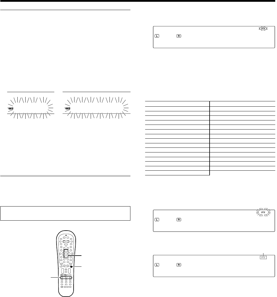
36 EN
1
Press the PTY key to activate the PTY search mode.
NE sW
When an RDS broadcast is received, the program type is shown on the
display. If no PTY data is available, or if the station is not an RDS
station, "NONE" is displayed.
2
While the "PTY" indicator is lit, use the Tune + /
-
keys to
select the program type of your choice.
w
Program type table
Program Type Name Display Program Type Name Display
Pop Music POP M Weather WEATHER
Rock Music ROCK M Finance FINANCE
Easy Listening Music EASY M Children’s Programmes CHILDREN
Light Classical Music LIGHT M Social Affairs SOCIAL
Serious Classical Music CLASSICS Religion RELIGION
Other Music OTHER M Phone In PHONE IN
News NEWS Travel TRAVEL
Current Affairs AFFAIRS Leisure LEISURE
Information INFO Jazz Music JAZZ
Sport SPORT Country Music COUNTRY
Education EDUCATE National Music NATION M
Drama DRAMA Oldies Music OLDIES
Culture CULTURE Folk Music FOLK M
Science SCIENCE Documentary DOCUMENT
Varied Speech VARIED
3
Press the PTY key to start searching.
Example: Searching for a Pop Music broadcast.
Display while searching. Blinks
PO MP
Program type name display
Display when a station is received. Goes out
BB MF1C
Station name display
•No sound is heard while "PTY" is blinking.
•If the desired program type cannot be found, "NO PROG" is
displayed, then after several seconds the display returns to the
original display.
To select another program type.
Repeat steps 1, 2 and 3.
Presetting RDS stations (RDS AUTO MEMORY)
This function automatically stores up to 40 RDS stations in the preset
memory. In order to use the PTY function, the RDS stations must be
stored in the preset memory using the RDS Auto Memory function.
1
Use the INPUT SELECTOR key (or the TUNER key) to select
tune as the source.
2
Use the BAND key (the Band key) to select he broadcast band
to "FM".
3
Press and hold the ENTER for more than 2 seconds will start
AUTO MEMORY.
AU OT
ME YROM
The blinking "AUTO" display and blinking "MEMORY" display
appear alternately.
•After a few minutes, up to 40 RDS stations are preset in
order from channel "01".
•Stations already stored in the preset memory may be replaced by
RDS stations. (i.e., If the RDS AUTO MEMORY function detects
15 RDS stations, the stations currently preset at numbers 01~15
will be replaced by the RDS stations.)
Tuning by Program TYpe (PTY search)
This function lets you set the tuner to automatically search for stations
which are currently broadcasting the type of program (genre) you want
to listen to.
Under certain receiving conditions, it may take more than 1
minute to complete the search.
PTY
Tune –
1
/ +
¡
Band
Multi %/fi
Lights up
Using RDS (Radio Data System) (For Europe only)
Preparations
•Execute the RDS auto memory procedure.
•Set the broadcast band to FM.
•Tune to an RDS station.
*5462/20-36/EN 04.4.13, 8:01 PM36
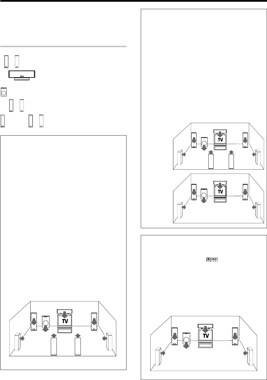
37 EN
Ambience effects
This receiver is equipped with listening modes that allow you to enjoy an
enhanced sonic ambience with a variety of video sources.
In order to obtain the optimum effect from the surround modes, make
sure to input the proper speaker settings beforehand. ¢
Surround modes
Dolby PRO LOGIC
II
x/ Dolby PRO LOGIC
II
Dolby Pro Logic IIx was designed specifically to provide a new sense
of spatiality, directionality and articulation of sounds from Dolby
Surround encoded sources.
This is achieved with an intelligent, built-in feedback logic design, a matrix
surround decoding and the decoding of stereo, full bandwidth surround
outputs. The PRO LOGIC IIx modes programmed into this receiver are
"MOVIE", "MUSIC" and "GAME". The "MOVIE" mode of the PRO LOGIC IIx
has preset characteristics to produce a calibrated, high-level surround
sound playback while the "MUSIC" mode has user-adjustable character-
istics to offer the three optional controls, like "Dimension", "Center Width"
and "Panorama" modes to allow optimization of the soundfields as
desired. The "Dimension" control allows the user to gradually adjust the
soundfield either towards the front or towards the rear; the "Center
Width" control allows various adjustment of the left-center-right speak-
ers’ balance; the "Panaroma" mode extends the front stereo image to
include the surround speakers for an exciting "wraparound" effect with
side wall imaging. The "GAME" mode is designed for playing video games
and enhances the powerful feeling of sound.
Dolby Digital EX
Dolby Digital EX is an extension of Dolby Digital technology, Dolby
Digital EX creates six full-bandwidth output channels from 6.1-chan-
nel sources. This is done using a matrix decoder that derives three
surround channels from the two in the original recording.
This is achieved by using three different surround signals, Left
Surround , Right Surround, and Back Surround, each driving its own
array of speakers. Think of it as adding a center channel for the rear
speakers, which give more diffuse and natural surround effect, even
if you wanted the ability to completely encircle the audience with
sound, positioning sound effects exactly where they wolud be heard
in real life.
Note
For best results, Dolby Digital EX should be used with movie
soundtracks recorded with Dolby Digital Surround EX which contain
a digital flag that will automatically activate this feature. However, for
titles released prior to late 2001, this feature has to be activated
manually.
This model lets you enjoy Dolby Digital (and Dolby Surround) program
sources, even if you connect only the Front Speakers. However, in
order to enjoy the benefit of true 6.1 channel Dolby Digital Surround
EX sound, KENWOOD recommends that you connect a full set of
speakers.
C
SW
RBLB
LR
LS RS
C
RBLB
LR
LS RS
SW
LR
(Front speakers)
C
(Center speaker)
SW
(Subwoofer)
LS RS
(Surround speakers)
BS
or
LB RB
(Surround back speakers)
C
LR
LS RS
SW
Dolby
PRO LOGIC IIx
Dolby
PRO LOGIC II
C
LR
LS RS
SW
Dolby Digital
Dolby Digital surround format lets you enjoy up to 5.1 channels of
digital surround sound from Dolby Digital program sources (such as
Laserdisc or DVD software marked ). Compared with previous
Dolby surround, Dolby Digital provides even better sound quality,
greater spatial accuracy, and improved dynamic range.
This model lets you enjoy Dolby Digital (and Dolby Surround) program
sources, even if you connect only the Front Speakers. However, in
order to enjoy the benefit of true 5.1 channel Dolby Digital surround
sound, KENWOOD recommends that you connect a full set of
speakers.
*5462/37-44/EN 04.4.13, 8:01 PM37
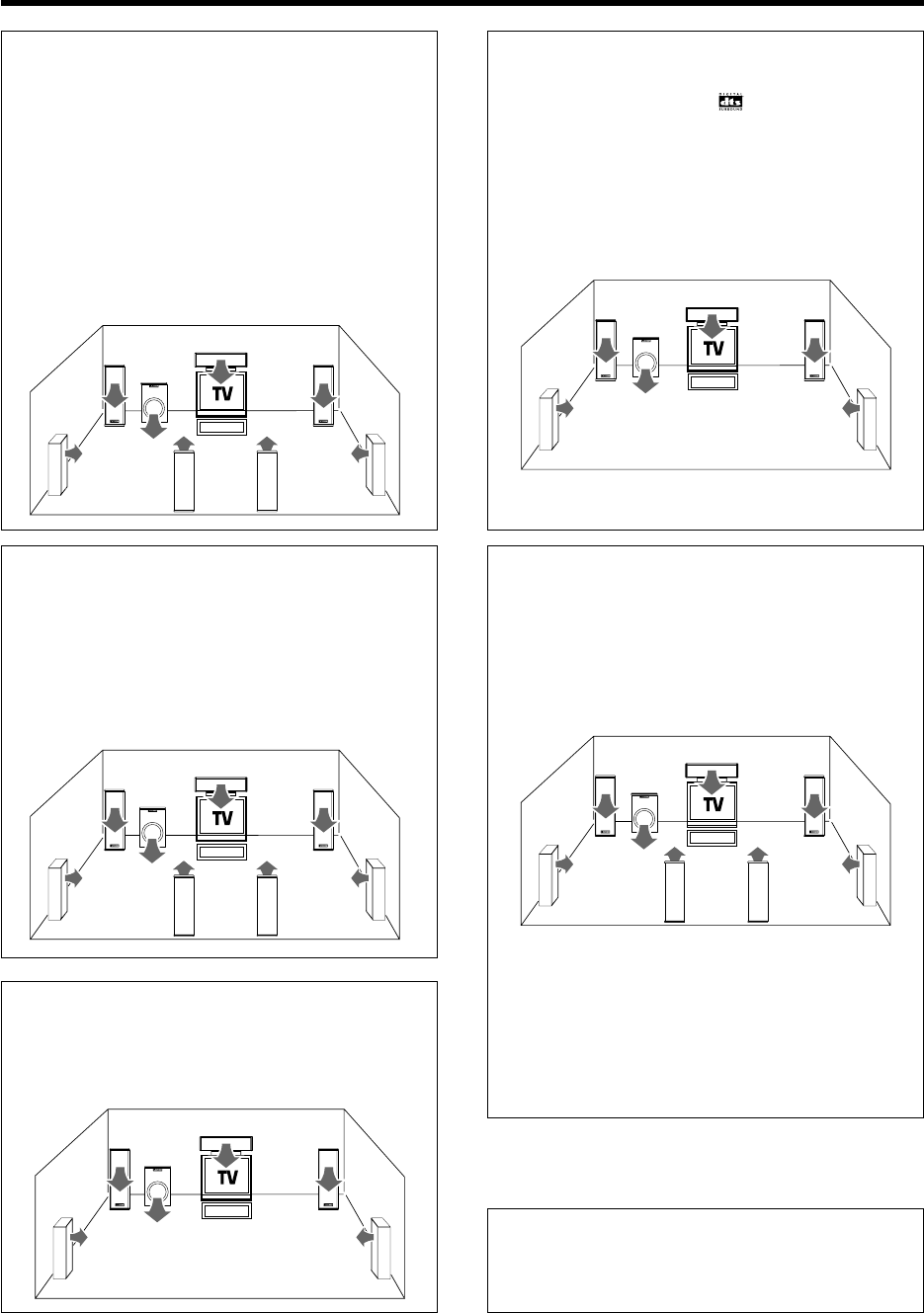
38 EN
Ambience effects
DTS-ES
The DTS-ES (Digital Theater System-Extended Surround) represents
6.1-channel Discrete Surround format, expanding upon 5.1 surround.
DTS-ES format is a 6.1 channel sound system for movie theaters that
includes an additional surround center channel matrixed within sur-
round left and surround right. It’s compatible on predecessor DTS 5.1
system. The extra channel allows more accurate placement and
steering of sound accross the rear soundstage.The DTS-ES receiver
will be required, to experience a discrete 6.1-channel mix.
The DTS-ES decoders used in home cinema systems have decoding
options for utilizing the extra channel, in addition to processing
existing 5.1 channel surround sound :
DTS-ES Discrete 6.1 and DTS-ES Matrix 6.1 add the surround back
channel audio to the DTS 5.1-channel format to improve the acoustic
positioning and makes acoustic image movement more natural with
the 6.1-channel reproduction.
C
RBLB
LR
LS RS
SW
DTS 96/24
The DTS 96/24 enables 5.1-channel playback with broad bandwidth
over 40 kHz and high resolution without affecting the picture quality
of DVD video. As it is compatible with the DTS surround playback, it
makes it possible to play DTS 5.1-channel surround audio even when
the AV amplifier incorporates only the DTS or DTS-ES decoder.
C
LR
LS RS
SW
DSP mode
The DSP mode lets you add the atmosphere of a live concert or hall
to almost any type of program source. These modes are particularly
effective when used with stereo program sources, like CD, television,
and FM radio. You might enjoy trying the ARENA, JAZZ CLUB,
THEATER, STADIUM or DISCO mode the next time you watch a
concert or sporting event!
What's DSP?
DSP stands for Digital Signal Processor.
The way a sound is heard in an actual environment depends on a
variety of different factors. One of the most important is reverberation
(the act of decaying elements of sound echoing in various places).
The DSP modes produce the feeling of presence by using the DSP to
create reverberation, without spoiling the sound quality of the original
signal.
LFE = Low Frequency Effects. This channel delivers separate non-
directional bass signals to the subwoofer for more dynamic deep bass
sound effects.
When there is a LFE channel input in the DOLBY DIGITAL or DTS
format, the "LFE" indicator lights on the display of the receiver.
NEO:6
NEO:6 is a new technology which decodes 2-channel signals into
6-channel signals using high-accuracy digital matrix technology.
For the best results, DTS-ES should be used with movie sound
tracks recorded with DTS-ES format which contain a digital flag
that will automatically activate this feature. However, for some
titles, this feature has to be activated manually.
According to the signals to be played back, DTS NEO:6 uses either
the NEO:CINEMA mode optimized for movie playback or the
NEO:MUSIC mode optimized for music playback.
C
RBLB
LR
LS RS
SW
C
RBLB
LR
LS RS
SW
DTS
The DTS employs a larger amount of data than Dolby Digital to play
surround sound with higher quality. The DTS can be used with DVD
and LaserDisc software carrying the mark. Although the number
of channels is 5.1 and identical to Dolby Digital, the DTS format
features lower audio compression rate in digital recording, which
enables audio with more profoundness and higher S/N. The wider
dynamic range and better channel separation also contribute to make
the surround sound more precise and larger in scale.
C
LR
LS RS
SW
*5462/37-44/EN 04.4.13, 8:01 PM38
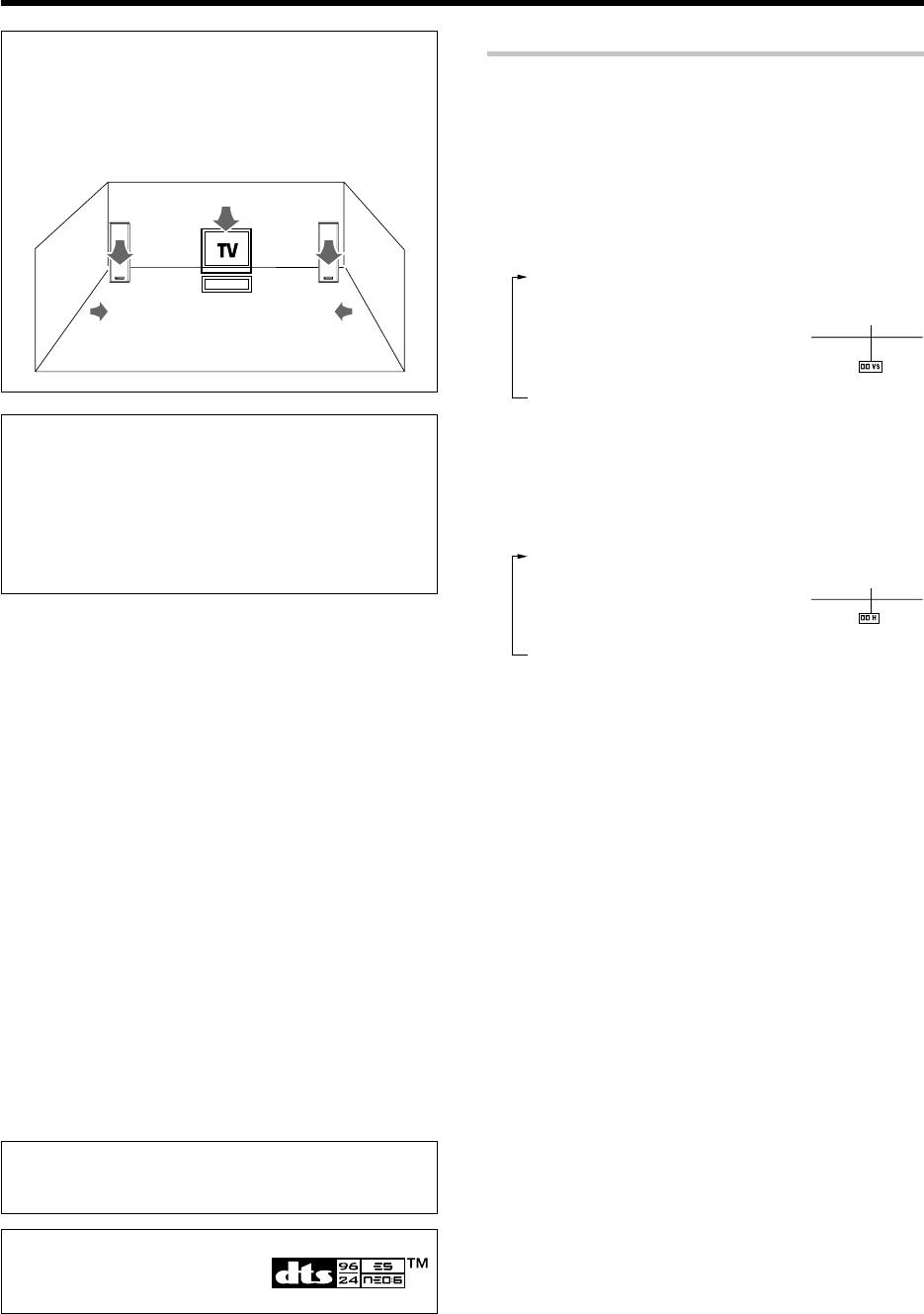
39 EN
“DTS”, “DTS-ES Extended Surround”,
“Neo:6” and “DTS 96/24” are trademarks
of Digital Theater Systems, Inc.
Manufactured under license from Dolby Laboratories. “Dolby”, “Pro
Logic”, “Surround EX” and the double-D symbol are trademarks of
Dolby Laboratories.
Virtual modes
The following modes allow you to enjoy powerful surround audio even
when you use only two speakers or listen through headphones.
÷In the Dolby Virtual Speaker and Dolby Headphone modes, only the listen
modes for 2 channels can be selected. Also, the desired listen mode may
be unable to be selected depending on the reproduced signals. ‚
How to set the Dolby Virtual Speaker mode
(when not using headphones):
Press the Dolby Virtual key for the following selections:
1"DVS WIDE" :
The virtual surround effect can be
given added expansion and spatial
feeling.
2"DVS REF" : *
Standard setting.
3"DVS OFF" : Cancel
* This mode can be selected only when the surround speaker
setting is OFF.
How to set the Dolby Headphone mode
(when using headphones):
Press the Dolby Virtual key for the following selections:
1"DH 1": Small, acoustically dry room.
2"DH 2": More lively room than "DH 1".
3"DH 3": Larger room than "DH 1" for
enhanced feelings of distance and
sound diffusion effect.
4"OFF": Cancel
÷The Dolby Virtual Speaker or Dolby Headphone mode is defeated when
the DUAL SOURCE mode or REC MODE is ON.
Lights up
Lights up
Dolby Virtual Speaker
The Dolby Virtual Speaker features a virtual surround sound field.
This implements an effect as if there are multiple speakers in the
listening room.
C
LR
LS RS
Dolby Headphone
When headphones are used in music listening, the audio of the left (or
right) channel reaches only the left (or right) year so the listener cannot
feel the presence of acoustic images on the front.
The Dolby Headphone simulates a virtual room and include its
acoustic characteristics in the left and right headphone signals. As a
result, the listener can hear the same components as in speaker
listening through the left and right years and therefore feel as if the
sound source is located on the front of the listener.
Ambience effects
*5462/37-44/EN 04.4.13, 8:01 PM39
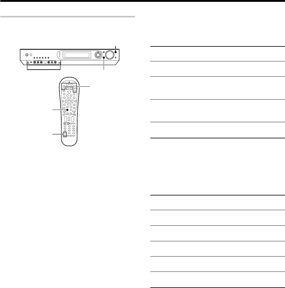
40 EN
Ambience effects
Input Mode
INPUT SELECTOR
LISTEN MODE
Listen Mode5/∞
Preparations
÷Turn ON related components.
÷Complete "Preparing for playback" (speaker settings).¢
÷Use the INPUT SELECTOR key (or Input Selector keys) to select
the component you wish to play back with surround sound.
÷Use the Input Mode key to select the input mode (analog or
digital) for the source you wish to play back. 8
÷Noise will be produced when a DTS source is played by
selecting the analog input.
1
Start playing the video software.
2
Press the LISTEN MODE key (or the Listen Mode
5
/
∞
keys)
to select the listening mode.
The listening mode settings are stored separately for each input
selector.
If the input mode is set to full auto ("AUTO DETECT" lights), this
model selects the optimal listening mode automatically based on the
type of input signal and the speaker settings.
Each press the LISTEN MODE key (or the Listen Mode 5/∞
keys) switches the setting as listed below.
The listening mode settings are different depending on
the type of input signal.
÷The "MULTI CH" indicator lights during playback through
multiple channels.
Surround play
The desired listen mode can be selected according to the input signal.
Main example of medium:
Multi-channel digital source such as DVD.
1"DOLBY D":
DOLBY DIGITAL surround
2"DOLBY D EX":
DOLBY DIGITAL EX surround
3"DOLBY D + PLIIx MOVIE":
DOLBY DIGITAL surround +
DOLBY PRO LOGIC IIx surround MOVIE mode*
4"DOLBY D + PLIIx MUSIC":
DOLBY DIGITAL surround +
DOLBY PRO LOGIC IIx surround MUSIC mode
5"STEREO":
Normal stereo playback.
* Can be selected only when two surround back speakers are con-
nected.
÷You can also adjust the midnight mode as desired. r
Main example of medium:
Multi-channel digital source such as DVD.
1"DTS":
DTS surround
2"DTS + NEO6 CINEMA":
DTS surround + DTS NEO:6 surround CINEMA mode
3"DTS-ES MATRIX 6.1":
DTS-ES 6.1-channel Matrix surround *1
4"DTS-ES DISCRETE 6.1":
DTS-ES 6.1-channel Discrete surround *2
5"DTS 96/24":
DTS 96/24 surround *3
6"STEREO":
Normal stereo playback.
*1 Can be selected only with DTS-ES 6.1ch Matrix Surround.
*2 Can be selected only with DTS-ES 6.1ch Discrete Surround.
*3 Can be selected only with DTS 96/24 Surround.
÷You can also adjust the midnight mode as desired. r
Listen modes available with Dolby Digital EX or Dolby Digital
playback:
("Dolby D" indicator lights up)
Listen modes available with DTS, DTS-ES (Matrix or Discrete)
or DTS-96/24 playback:
("DTS" indicator lights up)
Input selector keys
*5462/37-44/EN 04.4.13, 8:01 PM40

41 EN
Ambience effects
Switching the listen mode temporarily to the stereo mode
Press the Stereo key to switch the current listen mode temporarily to the
Stereo mode. Pressing the key again restores the original listen mode.
÷The original listen mode is also restored when the input selector is
switched or the receiver is turned OFF then ON again.
Main example of medium:
Digital sources including DVD 96 kHz linear PCM and CD.
Analog source such as VCR or radio broadcasting.
1"PL IIx MOVIE":
DOLBY PRO LOGIC IIx surround MOVIE mode *1
2"PL IIx MUSIC":
DOLBY PRO LOGIC IIx surround MUSIC mode *1 *2
3"PL IIx GAME":
DOLBY PRO LOGIC IIx surround GAME mode *1
4"PL II MOVIE":
DOLBY PRO LOGIC II surround MOVIE mode
5"PL II MUSIC":
DOLBY PRO LOGIC II surround MUSIC mode *2
6"PL II GAME":
DOLBY PRO LOGIC II surround GAME mode
7"PRO LOGIC":
DOLBY PRO LOGIC surround
8"NEO6 CINEMA" or "NEO6 96K CINEMA":
DTS NEO:6 surround CINEMA mode
9"NEO6 MUSIC" or "NEO6 96K MUSIC":
DTS NEO:6 surround MUSIC mode *3
0"ARENA":
DSP surround ARENA mode *4
-"JAZZ CLUB":
DSP surround JAZZ CLUB mode *4
="THEATER":
DSP surround THEATER mode *4
~"STADIUM":
DSP surround STADIUM mode *4
!"DISCO":
DSP surround DISCO mode *4
@"STEREO":*5
Normal stereo playback.
*1 Cannot be selected in Dolby Virtual Speaker and Dolby Headphone
modes.
*2 The sound field can be adjusted as desired using the PANORAMA,
DIMENSION and CENTER WIDTH modes. e
*3 The sound field can be adjusted as desired using the CENTER IMAGE
modes. r
*4 Cannot be selected in Dolby Virtual Speaker and Dolby Headphone
modes or with a 96 kHz linear PCM signal input.
The effect level of the DSP surround mode can be adjusted as
desired. w
*5 In Dolby Virtual Speaker and Dolby Headphone modes, the Dolby
Digital signal input cannot be listened to in the stereo mode.
Listen modes available with analog or PCM playback:
3
Adjust the volume.
Note
÷Certain modes may be unavailable depending on the type of input
signal or speaker setting.
÷If an optimum surround effect cannot be obtained or the desired
mode cannot be selected, check the speaker and input mode
settings. 8¢
Dolby Digital Surround EX compliant disc :
Dolby Digital Surround EX compliant disc contains identification signals.
When you choose FULL AUTO during "Input mode settings" (8), this
amplifier detects the identification signals and change the LISTEN mode to
the DOLBY DIGITAL EX (Dolby Digital Surround EX mode) automatically.
But sometimes we find some discs which are Dolby Digital Surround EX
compliant disc but it does not contain the identification signals. If you find the
notice like “Surround EX” on the label of disc or package, you can choose
DOLBY DIGITAL EX, then you can enjoy Dolby Digital Surround EX sound.
*5462/37-44/EN 04.4.13, 8:01 PM41
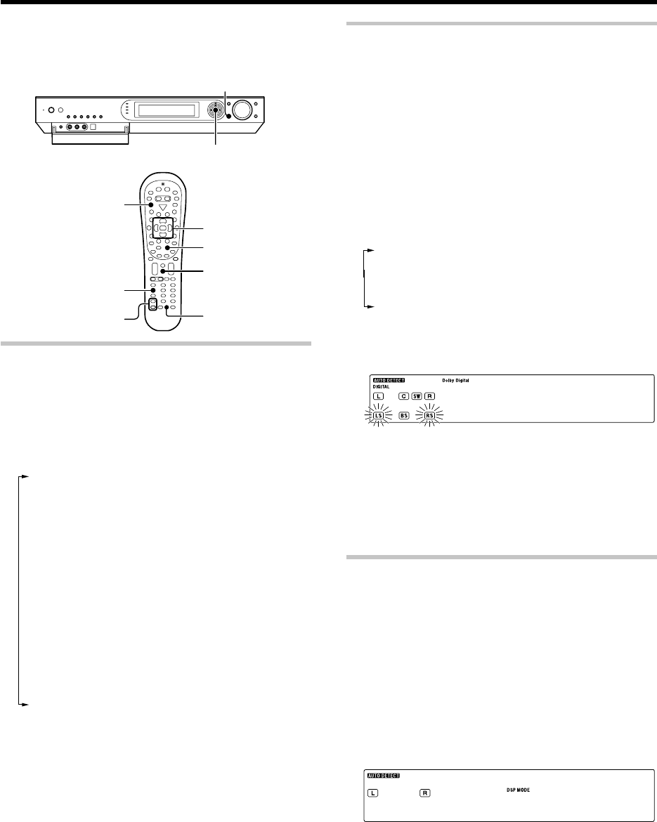
42 EN
LISTEN MODE
MULTI CONTROL %
/
fi
/
@
/
#
Stereo
Listen Mode5/∞
Multi %
/
fi
/
@
/
#
Enter
ENTER
Dimmer
Sound
Sleep
RCV Mode
1Press the RCV Mode key on the remote control unit to set
it to the receiver control mode.
2Press the Sound key
3
Press MULTI CONTROL @ / # (or the Multi@ / # key) to
select the setting item and press ENTER (or the Enter key).
Note that some items are not displayed in certain modes.
1"SP LEVEL": *1
Adjusting the volume level of each channel
2"INPUT": (Analog mode only) •
Input level adjustment
3"TONE": *2 º
Tone level adjustment
4"EFFECT": (DSP mode only)
DSP effect leve adjustment
5"DUAL MONO": *3 e
Selection between Stereo, Main audio, Sub audio and
Main + Sub audio
6"MIDNIGHT": *4 r
Midnight mode adjustment
7"PANORAMA": *5 e
Panorama mode ON/OFF
8"DIMENSION": *5 e
Dimension adjustment
9"C WIDTH": *5 e
Center width adjustment
0"C
IMAGE
": *6 r
Center image mode adjustment
*1 The setting in the SOUND mode is temporary. It returns automati-
cally to the original level set in "Speaker settings" when the
receiver is turned OFF/ON.
*2 PCM stereo and analog stereo mode only.
*3 DOLBY DIGITAL mode only
*4 DOLBY DIGITAL, DTS mode only
*5 Only when the input signal is a 2-channel signal in the DOLBY PRO
LOGIC IIx MUSIC or DOLBY PRO LOGIC II MUSIC mode.
*6 Only when the input signal is a 2-channel signal in the DTS
NEO:6 MUSIC mode.
4Use the MULTI CONTROL % / fi (or the Multi % / fi) to
adjust the setting as desired.
÷The adjustment item is displayed for approximately 20 seconds.
5Press the Sound key again to return to the input indication.
You can make further adjustments to the sound while listening to
playback in the surround mode.
÷The mode using Sound key is defeated when the REC MODE is
ON. ¤
Adjusting the sound
Adjusting the volume level of each channel
The volume levels of the center speaker, subwoofer, surround speaker
and surround back speaker channels can be adjusted during playback.
1Press the RCV Mode key on the remote control unit to set
it to the receiver control mode.
2Press the Sound key
3Use the MULTI CONTROL @ / # (or the Multi @ / # keys)
to select "SP LEVEL" on setup displays, and press the
ENTER (or Enter key).
4Use the MULTI CONTROL @ / # (or the Multi @ / # keys)
to select the speaker.
1Subwoofer level adjustment ("SW" indicator blinks)
2Center speaker level adjustment ("C" indicator blinks)
3Surround speaker level adjustment ("LS", "RS" indicator
blinks)
4Surround back speaker level adjustment ("LB", "RB" or
"BS" indicator blinks)
5Use the MULTI CONTROL % / fi (or the Multi % / fi keys)
to adjust the speaker volume level.
+1 +1 ) d/)B
÷The level of each speaker channel can be adjusted in 1 dB
steps between -10 dB and +10 dB.
6Repeat steps 4 and 5 as required.
7Press the Sound key again to return to the input indication.
÷The setting in the SOUND mode is temporary. It returns automati-
cally to the original level set in "Speaker settings" when the
receiver is turned OFF/ON.
Adjusting the DSP effect level
(DSP mode only)
The DSP effect level can be adjusted when the listen mode is a DSP surround
mode "ARENA", "JAZZ CLUB", "THEATER", "STADIUM" or "DISCO".
1Press the RCV Mode key on the remote control unit to set
it to the receiver control mode.
2Press the Sound key
3Use the MULTI CONTROL @ / # (or the Multi @ / # keys)
to select "EFFECT" on setup displays, and press the
ENTER (or Enter key).
4Use the MULTI CONTROL % / fi (or the Multi % / fi) to
adjust the
EFECT
LEVEL.
EF TCEF3
÷
The DSP effect level can be adjusted in the range between 1 and 5.
5Press the Sound key again to return to the input indication.
Convenient functions
*5462/37-44/EN 04.4.13, 8:01 PM42
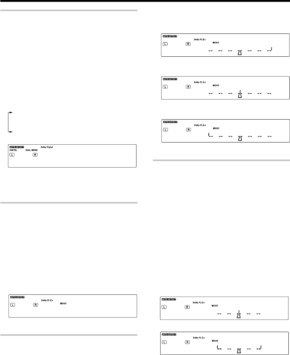
43 EN
Convenient functions
Switching between main audio and sub audio
(DOLBY DIGITAL mode only)
When listening to audio multiplex broadcasting such as two-language
satellite digital broadcasting, the main and sub audio can be switched over.
1Press the RCV Mode key on the remote control unit to set
it to the receiver control mode.
2
Press the Sound key while the "DUAL MONO" indicator is lit.
3Use the MULTI CONTROL @ / # (or the Multi @ / # keys)
to select "DUAL MONO" on setup displays, and press the
ENTER (or the Enter key).
4Use the MULTI CONTROL % / fi (or the Multi % / fi keys)
to select the audio.
1"MAIN": The main audio is output.
2"SUB": The sub audio is output.
3
"MAIN + SUB": The mixture of main audio and sub audio is output.
4"STEREO": The left channel outputs the main audio and the
right channel outputs the sub audio.
MA AIMNI N
5Press the Sound key again to return to the input indication.
÷If the audio multiplex broadcasting is not monaural, the audio cannot
be switched on this receiver. In this case, use the audio switching
function on the tuner.
Panorama mode
(Only when the input signal is a 2-channel signal in the DOLBY PRO
LOGIC
II
x MUSIC or DOLBY PRO LOGIC
II
MUSIC mode)
When listening to music, you will be able to enjoy the "wraparound"
sound effect when you adjust the panorama mode.
1Press the RCV Mode key on the remote control unit to set
it to the receiver control mode.
2Press the Sound key
3Use the MULTI CONTROL @ / # (or the Multi @ / # keys)
to select "PANORAMA" on setup displays, and press the
ENTER (or the Enter key).
4Use the MULTI CONTROL % / fi (or the Multi % / fi) to
select PANORAMA ON or OFF.
ON
5Press the Sound key again to return to the input indication.
Dimension mode
(Only when the input signal is a 2-channel signal in the DOLBY PRO
LOGIC
II
x MUSIC or DOLBY PRO LOGIC
II
MUSIC mode)
When listening to music with certain recordings, you will also be able to
achieve a suitable balance from all the speakers by adjusting the
dimension mode.
1Press the RCV Mode key on the remote control unit to set
it to the receiver control mode.
2Press the Sound key
3Use the MULTI CONTROL @ / # (or the Multi @ / # keys)
to select "DIMENSION" on setup displays, and press the
ENTER (or Enter key).
4Use the MULTI CONTROL % / fi (or the Multi % / fi) to
adjust the soundfield towards the rear or the front.
Soundfield is adjusted towards the front.
R F
↓
Standard setting.
R F
↓
Soundfield is adjusted towards the rear.
R F
5Press the Sound key again to return to the input indication.
Center Width mode
(Only when the input signal is a 2-channel signal in the DOLBY PRO
LOGIC
II
x MUSIC or DOLBY PRO LOGIC
II
MUSIC mode)
Center width adjustment allows you to enjoy an enchanced sound when
listening to music through center image from only center speaker, or left
and right speakers or various combinations adjustments.
1Press the RCV Mode key on the remote control unit to set
it to the receiver control mode.
2Press the Sound key
3Use the MULTI CONTROL @ / # (or the Multi @ / # keys)
to select "C WIDTH" on setup displays, and press the
ENTER (or the Enter key).
÷When the center speaker is switched OFF, this mode will
not be effective.
4Use the MULTI CONTROL % / fi (or the Multi % / fi) to
adjust the left-center-right output.
Center image will be heard from center speaker only.
L R
Center image will be heard from left and right speakers only.
L R
÷When in other position, center image from center speaker,
left and right speakers can be heard simultaneously with
various combinations.
5Press the Sound key again to return to the input indication.
*5462/37-44/EN 04.4.13, 8:01 PM43
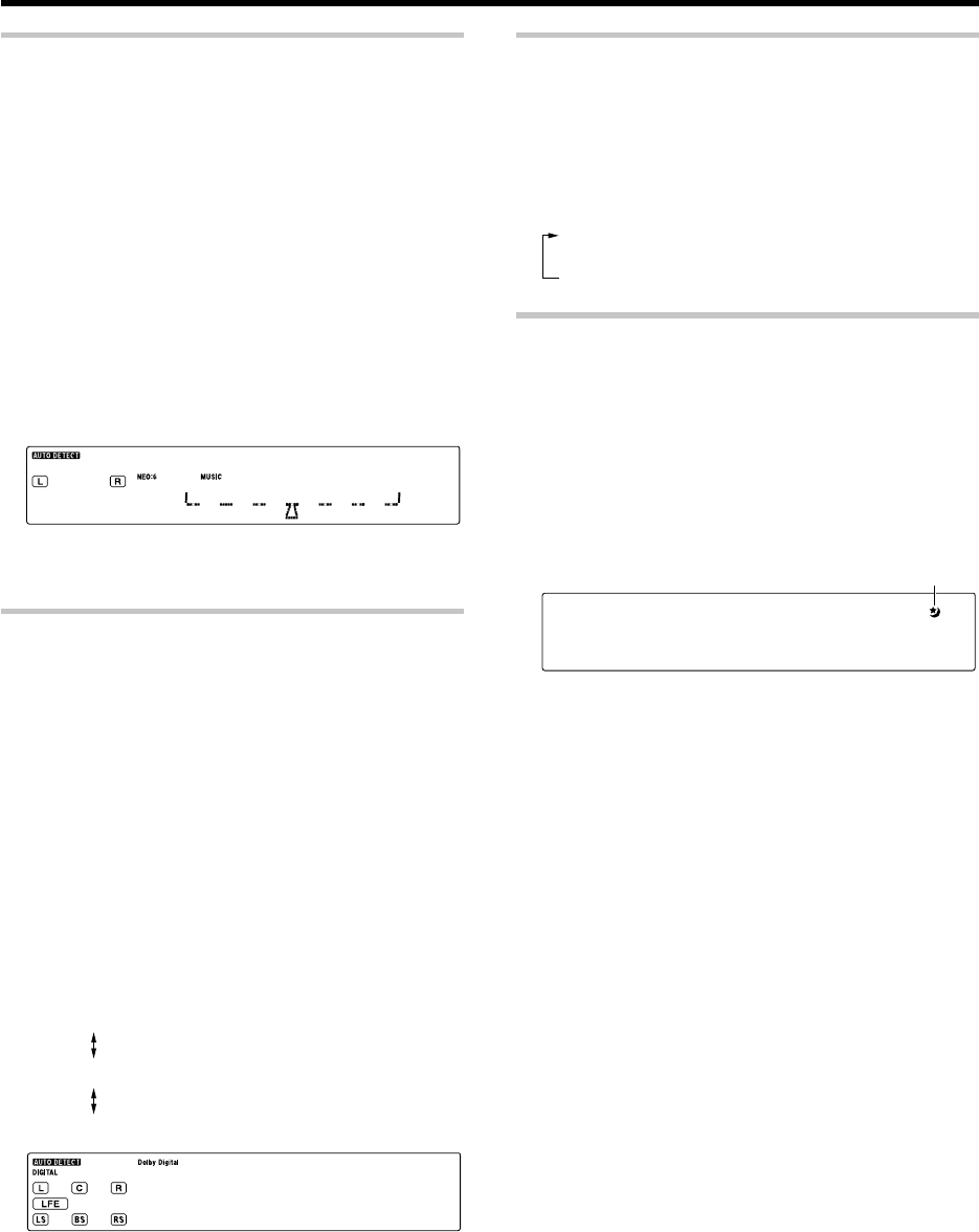
44 EN
Convenient functions
Center Image mode
(Only when the input signal is a 2-channel
signal in the DTS NEO:6 MUSIC mode.)
In the CENTER IMAGE setting mode of the NEO:6 MUSIC listen mode,
it is possible to enhance the center channel audio by adjusting the center
signal component.
1Press the RCV Mode key on the remote control unit to set
it to the receiver control mode.
2Press the Sound key
3Use the MULTI CONTROL @ / # (or the Multi @ / # keys)
to select "C IMAGE" on setup displays, and press the
ENTER (or the Enter key).
÷When the center speaker is switched OFF, this mode will
not be effective.
4Use the MULTI CONTROL % / fi (or the Multi % / fi) to
adjust the left-center-right output.
L R
÷Adjust the center component level.
5Press the Sound key again to return to the input indication.
Midnight mode
(DOLBY DIGITAL and DTS mode only)
When watching movies at night , you might not be able to raise the volume
as loud as normal. Midnight mode compresses the dynamic range of
previously specified parts of the DOLBY DIGITAL or DTS sound track (like
scenes with sudden increases in volume) to minimize the difference in
volume between the specified and non-specified parts. This makes it easy
to hear all of the sound track, even when listening at low volumes.
1Press the RCV Mode key on the remote control unit to set
it to the receiver control mode.
2Press the Sound key
3Use the MULTI CONTROL @ / # (or the Multi @ / # keys)
to select "MIDNIGHT" on setup displays, and press the
ENTER (or the Enter key).
÷This can be selected only if DVD, VIDEO 1, VIDEO 2, AUX
or GAME is selected as the source and the listen mode is set
to "DOLBY DIGITAL" or "DTS".
4Use the MULTI CONTROL % / fi (or the Multi % / fi) to
select the "MIDNIGHT2", "MIDNIGHT1" or "OFF" setting.
1"MIDNIGHT2": Large effect
Suitable for late-night use.
2"MIDNIGHT1": Medium effect
3"OFF"
MI H TGIND1
÷The adjustment item is displayed for approximately 20 sec-
onds.
÷Some DOLBY DIGITAL or DTS software may not be compat-
ible with the Midnight mode.
5Press the Sound key again to return to the input indication.
Display dimmer adjustment
The dimmer function lets you select the brightness of the receiver's
display. You might find this useful if you darken your room to watch
movies or listen to music.
Each time you press the Dimmer key, the display’s brightness
changes among the three available settings.
Select the brightness level you find most pleasing.
1Bright
2Dark
3Dark (Indicators on the receiver are also OFF.)
Sleep timer
The sleep timer function turns the receiver OFF (to the standby mode)
automatically when the set timer period has elapsed. The sleep timer
period can be set in 10-minute steps up to 90 minutes.
Press the Sleep key repeatedly until the desired period before
turning the receiver OFF (standby mode) is displayed.
÷Each press increments the sleep timer period by 10 minutes.
10 = 20 = 30 .....70 = 80 = 90 = Cancel = 10 = 20 = ...
sL O3PEE)
÷Pressing the Sleep key after the sleep timer has started
allows you to check the remaining time period.
÷To cancel the sleep timer, turn the receiver OFF (standby
mode) or press the Sleep key repeatedly until the Sleep
timer indicator disappears.
The sleep timer indicator lights up
*5462/37-44/EN 04.4.13, 8:01 PM44
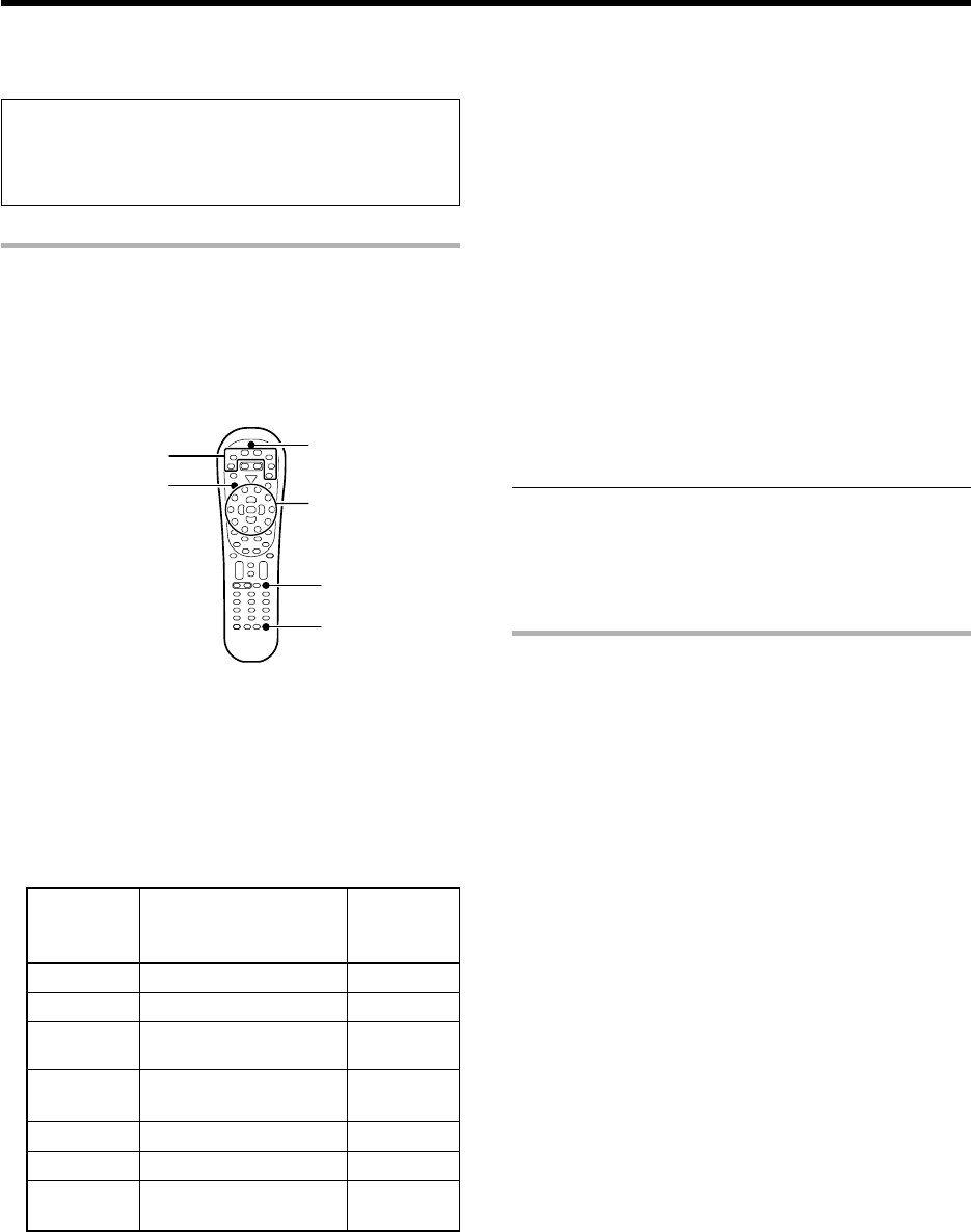
45 EN
Basic remote control operations for other components
The remote control supplied with this receiver is also capable of
controlling components from a variety of manufacturers once you
register the appropriate setup codes into the remote control unit.
Low battery warning
Replace all two batteries with new ones when you notice a shortening
of the distance from which the remote control will operate. The
remote control is designed to retain setup codes in memory while you
change batteries.
Registering setup codes for other components
When the setup code defined for remote control of every system
component is registered in one of the input selector keys of the remote
control unit, you can control that component simply after selecting it
using the corresponding input selector key of the remote control unit.
÷When recording audio on a VCR or MD recorder, for example, you can
also control the system component by switching only the remote
control unit, without switching the input source of the receiver.
1
Find the setup code of the component to be registered.
Refer to the setup code lists to find the setup code for the component
to be registered. uQ
Example: To register a DVD made by KENWOOD, you would enter
"0490" or "0534".
2
Press the input selector key (DVD, VID1, VID2, AUX, F.AUX or
Game) you want to register a system component.
The following table shows the type of components that can be
registered in each input selector key.
÷Make sure that a source belonging to the registerable componentc
is connected to the corresponding input jacks on the receiver.
÷A second DVD recorder, CD player or VCR can also be connected
by changing the assignment of the registerable component de-
vices. See "Re-assigning device keys" on page 46.
3
Press and hold the Remote Setup key until the LED blinks
twice, then release the Remote Setup key.
÷Proceed to the next steps in less than 10 seconds after the LED
blinks twice.
4
Press the numeric key to enter the four-digit code for the
component to be registered.
÷The LED blinks twice when registration is completed successfully.
5
Ensure that the registered component functions properly.
To ensure the proper function, perform the following operation
and check if the component functions as intended.
Point the remote control unit to the component and press the SRC
Power key (or the TV Power key if the component is a TV) once. If the
setup code is registered properly, the component should be turned ON
or OFF. If the component is a VCR, turn the VCR ON and load a video
tape and perform an operation such as playback. The VCR should
function as controlled if its setup code is registered properly.
If the component does not function properly:
If more than one setup code is listed for the component, try
registering another setup code by performing steps 3 to 5.
÷Repeat steps 1 to5 above to register the setup code of
another component.
÷To change the registered setup code, register a new setup
code again by performing steps 1 to 5 above.
Note
Although each setup code is designed to work with a number of
different models, certain codes may not work with some models.
(Also, certain codes may only operate some of the functions available
on a given model.)
Searching for your code
If your component does not respond after trying all the codes listed for
your component, or if your component is not listed at all, try searching for
your code.
For example, to search for a code for your TV.
1
Press the TV key once.
When searching for the setup code of a component other than TV:
Press the desired input selector key instead of the TV key.
2
Press and hold the Remote Setup key until the LED blinks
twice, then release the Remote Setup key.
÷Proceed to the next steps in less than 10 seconds after the LED
blinks twice.
3
Press the numeric key to enter "9 9 1".
÷The LED will blink twice.
4
Point the remote control at the TV and slowly alternate
between pressing the TV Power and TV keys. Stop when the
TV turns on or off.
÷In the search mode, the remote control will send IR codes
from its library to the selected device, starting with the most
popular code first.
When searching for the setup code of a component other than TV:
To search for the setup code of a DVD, CD, MD or VCR, press the
input selector key pressed in 1 and the SRC Power key alternately
and check if the component to be registered is turned ON and OFF.
To search for the setup code of a VCR, turn the VCR ON, load a tape
and press the input selector key pressed in step 1 (i.e. VID1) and an
operation key such as the play key alternately and check if the VCR
is controlled as intended.
5
Press the Remote Setup key once to lock in the code.
LED
Remote
Setup
SRC Power
TV
Input selector keys
Numeric keys
DVD DVD player DVD
VID1 VCR VIDEO1
VID2 VIDEO2
Satellite Receivers
AUX AUX
F. AUX DVD player FRONT AUX
Game DVD player GAME
TV TV (including TVs
-
incorporating VCR)
Input jacks
where the
component is
connected
Registerable component
Cable Converters
CD player,
MD recorder (KENWOOD)
Input selector
key
*5462/45-59/EN 04.5.12, 4:16 PM45
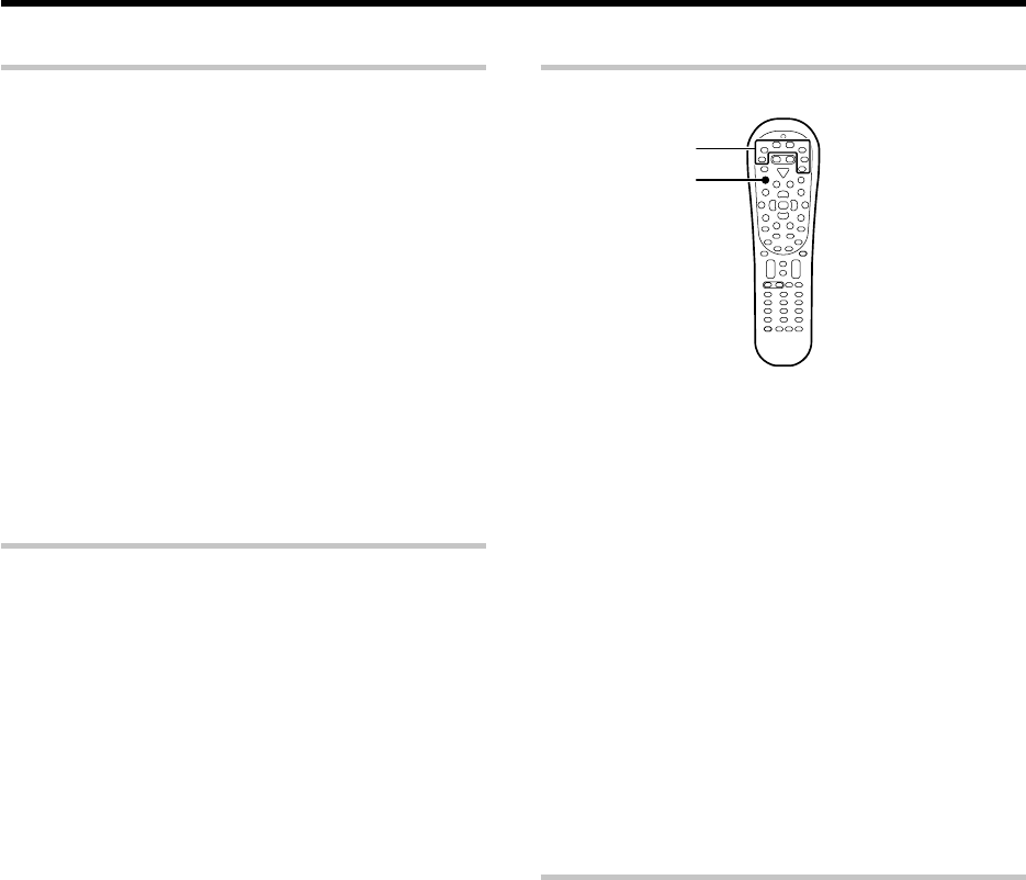
46 EN
Checking the codes
The 4-digit setup codes registered in the input selector keys can be
checked as follows.
1
Press the input selector key in which the setup code of the
desired component is registered.
2
Press and hold the Remote Setup key until the LED blinks
twice, then release the Remote Setup key.
÷Proceed to the next steps in less than 10 seconds after the LED
blinks twice.
3
Press the numeric key to enter "9 9 0".
÷The LED will blink twice.
4
Press the numeric key "1" once.
The LED blinks for the same number of times as the numeral in the
first digit of the 4-digit code. When the registered setup code is
"1338", for example, the LED will blink once. If a code digit is "0", the
LED will not blink.
5
Repeat step
4
three more times for the remaining digit.
Use "2" for the second digit, "3" for the third digit, and "4"
for the fourth digit.
Re-assigning device keys
The type of component device that can be registered is assigned in
advance in each input selector key, but this assignment can be changed
as desired by the user.
For example, the initial status is set so that a VCR can be registered in the
input selector VID1 key. If you want to register the setup code of a DVD
player in the VID1 key just like in the DVD key, reassign the key (change
the registerable component type assignment for the input selector key)
as described below.
1
Press and hold the Remote Setup key until the LED blinks
twice, then release the Remote Setup key.
÷Proceed to the next steps in less than 10 seconds after the LED
blinks twice.
2
Press the numeric key to enter "9 9 2".
÷The LED will blink twice.
3
Press the DVD key once, then press the VID1 key once.
The LED blinks twice, and it is possible to register the setup code
of a DVD player in the VID1 key just like in the DVD key. Now
register the setup code according to the model of the DVD player.
The combination of components assignable to the input selector
keys can be changed by pressing different keys in step 3. For
example, to change the key assignment so that the same compo-
nent as that registered in input selector "B" key can be registered
in input selector "A" key, press the "B" key then the "A" key after
entering "9 9 2" with the numeric keys.
÷
For the originally assigned relationship between the input selector keys
and system component types, see the table on the previous page.
÷To restore the original component type assignment of an input
selector key, press that input selector key twice after entering "9 9 2".
÷It is not possible to register a component in the TUNER key.
Examples of key re-assignment and the order of pressing the keys:
Registration of a DVD player in the VID1 key
To change the VID1 key to another DVD:
"9 9 2" \ "DVD" \ "VID1"
Restoration of the original key assignment
To return the VID1 key to the VID1 key:
"9 9 2" \ "VID1" \ "VID1"
Registration of a VCR in the VID2 key
To change the VID2 key to another VCR:
"9 9 2" \ "VID1" \ "VID2"
Restoration of the original key assignment
To return the VID2 key to the VID2 key:
"9 9 2" \ "VID2" \ "VID2"
Basic remote control operations for other components
Operating other components
This operation lets you operate the registered components.
1
Use the Input Selecter keys to select the component you desire.
When the input selector key is pressed, the system component
registered in the pressed key becomes ready to be controlled. The input
selector of the receiver is also switched accordingly. If you want to
control the component registered in the remote’s input selector key
without switching the receiver’s input selector to that source, press and
hold the input selector key for more than 3 seconds.
÷To put the remote control unit to the receiver control mode, press
the RCV Mode key.
2
Turn the component ON.
÷A DVD player, CD player, MD recorder or VCR registered in one of the
remote’s input selector keys can be turned ON by pressing the
remote’s SRC Power.
÷A TV registered in one of the remote’s input selector keys can be
turned ON by pressing the remote’s TV Power key.
3
Press the operation keys you desire.
÷For the keys that can be used with each system component, see
pages 58 to 59.
Clearing all of the settings registered or
stored in the remote control unit
You can reset the remote control unit to the initial status after purchase,
clearing all of the component registration using setup codes and other
data stored using the learning functions.
1
Press and hold the Remote Setup key until the LED blinks
twice, then release the Remote Setup key.
÷Proceed to the next steps in less than 10 seconds after the LED
blinks twice.
2
Press the numeric key to enter "9 8 1".
÷The LED blinks four times, and all of the data you registered
or stored in the remote control unit is cleared.
SRC Power
Input selector keys
*5462/45-59/EN 04.4.13, 8:01 PM46
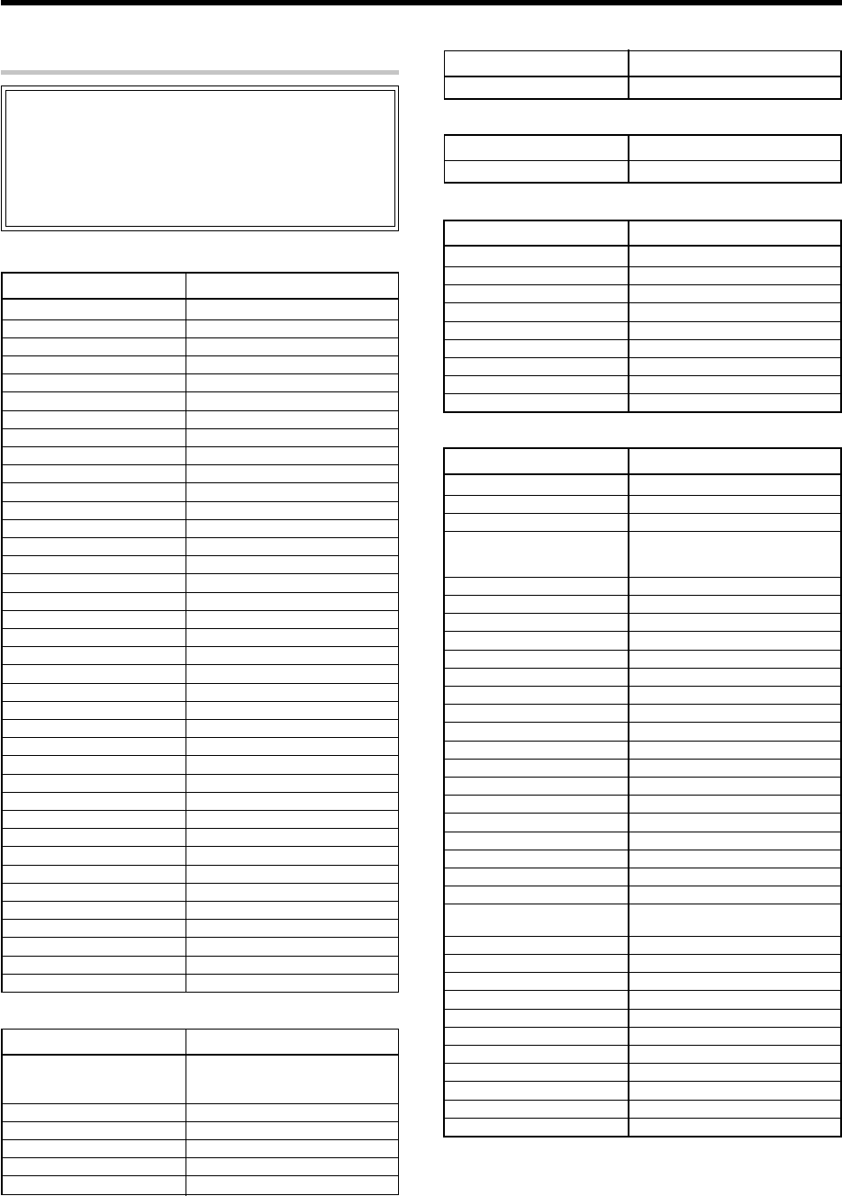
47 EN
Basic remote control operations for other components
ABC 0003, 0008, 0014
Americast 0899
Bell & Howell 0014
Bell South 0899
Clearmaster 0883
ClearMax 0883
Coolmax 0883
Director 0476
General Instrument 0476, 0810, 0276, 0003
GoldStar 0144
Hamlin 0009, 0273
Jerrold 0476, 0810, 0276, 0003, 0014
Memorex 0000
Motorola 0476, 0810, 0276, 1254, 1376
Pace 0237
Panasonic 0000, 0107
Paragon 0000
Philips 0305, 0317
Pioneer 0877, 1877, 0144, 0533
Pulsar 0000
Quasar 0000
RadioShack 0883
Regal 0279, 0273
Runco 0000
Samsung 0144
Scientific Atlanta 877, 1877, 0477, 0008
Sony 1006
Starcom 0003
Supercable 0276
Supermax 0883
Torx 0003
Toshiba 0000
Tristar 0883
V2 0883
Viewmaster 0883
Vision 0883
Vortex View 0883
Zenith 0000, 0525, 0899
Maker Setup codes
Cable Converters
Kenwood 0681, 0826, 0626, 0028, 0037,
0339, 1490, 0338, 0523, 0859,
0190, 0340, 0677, 0858, 1338
Marantz 0626
Optimus 0037
Philips 0626
Sharp 0037
Yamaha 0036
Maker Setup codes
CD player
Kenwood 0681, 0826, 1339
Maker Setup codes
MD recorder
AlphaStar 0772
Chaparral 0216
Crossdigital 1109
DirecTV 0392, 0566, 0639, 1639, 1142,
0247, 0749, 1749, 0724, 0819,
1856, 1076, 1109, 0099
Dish Network System 1005, 0775
Dishpro 1005, 0775
Echostar 1005, 0775
Expressvu 0775
GE 0566
General Instrument 0869
GOI 0775
Hitachi 0819
HTS 0775
Hughes Network Systems 1142, 0749, 1749
JVC 0775
Magnavox 0724, 0722
Memorex 0724
Mitsubishi 0749
Motorola 0869
Next Level 0869
Panasonic 0247, 0701
Paysat 0724
Philips 1142, 0749, 1749, 0724, 1076,
0722, 0099
Proscan 0392, 0566
RadioShack 0869
RCA 0392, 0566, 0855, 0143
Samsung 1276, 1109
SKY 0856
Sony 0639, 1639
Star Choice 0869
Tivo 1142
Toshiba 0749, 1749, 0790, 1285
Uniden 0724, 0722
Zenith 0856, 1856
Maker Setup codes
Satellite Receivers
Macro Image Technology 1383
MyHD 1383
Panasonic 1120
Pioneer 1010
Princeton 0113, 0295
Samsung 1490
Sensory Science 1126
Sharp 1010
Viewsonic 1329
Maker Setup codes
Video Accessories
Kenwood (Sirius Satellite Radio)
2000
Maker Setup codes
Audio Amp/Tuners
Even when a component is manufactured by a maker listed in the setup
code chart, it may be unable to be registered depending on the model and
year of production. Also, when a setup code of a non-KENWOOD maker
is registered, certain component models may be unable to be controlled
or only the limited functions may be controllable. In this case, it is
recommended to use the remote control unit provided with the system
component. For how to register the setup codes, read "Registering
setup codes for other components" carefully. t
Setup code chart (RC-R0730) (For U.S.A., Canada
and Australia)
*5462/45-59/EN 04.4.13, 8:01 PM47

48 EN
Admiral 0093, 0463
Aiko 0092
Aiwa 1914
Akai 0812, 0702, 0030, 0672
Albatron 0843
America Action 0180
Ampro 0751
Anam 0180
AOC 0030
Apex Digital 0748, 0765, 1943
Audiovox 0451, 0180, 0092
Bell & Howell 0154
Bradford 0180
Broksonic 0236, 0463, 1935, 1929, 1938
Candle 0030
Carnivale 0030
Carver 0054
Celebrity 0000
Celera 0765
Changhong 0765
Citizen 0060, 0030, 1928, 0092
Clarion 0180
Contec 0180
Craig 0180
Crosley 0054
Crown 0180
Curtis Mathes 0047, 0054, 0154, 0451, 0093,
0060, 0702, 0030, 0145, 0166,
1919, 1347
CXC 0180
Daewoo 0451, 1661, 0672, 1928, 0092
Denon 0145
Dumont 0017
Durabrand 0180, 0178
Dwin 0720
Electroband 0000
Elektra 0017, 1661
Emerson 0154, 0236, 0463, 0180, 0178,
0171, 1944, 1929, 1928
Envision 0030
Epson 0833
Fisher 0154
Fujitsu 0853, 0809, 0683
Funai 0180, 0171
Futuretech 0180
Gateway 1756, 1755
GE 0047, 0051, 0451, 0178, 1347,
1922, 1919, 1917
Gibralter 0017, 0030
GoldStar 0030, 0178, 1926
Grunpy 0180
Hallmark 0178
Harman/Kardon 0054
Harvard 0180
Havermy 0093
Hello Kitty 0451
Himitsu 0180
Hisense 0748
Hitachi 1145, 0145
Hyundai 0849
Infinity 0054
Inteq 0017
Maker Setup codes
TV
JBL 0054
JCB 0000
JVC 0053
KEC 0180
Kenwood 0030
KLH 0765
KTV 0180, 0030
LG 0856
LXI 0047, 0054, 0154, 0156, 0178
Magnasonic 1928, 1913
Magnavox 0054, 0030, 1454, 0706, 1254,
1931, 1913
Marantz 0054, 0030
Matsushita 0250, 0650
Megatron 0178, 0145
Memorex 0154, 0463, 0150, 0178, 1926
MGA 0150, 0030, 0178
Midland 0047, 0017, 0051
Mitsubishi 0093, 0150, 1250, 0178, 1917
Monivision 0843
Motorola 0093
MTC 0060, 0030
Multitech 0180
NAD 0156, 0178, 0866
NEC 0030, 1704, 0497
Nikko 0030, 0178, 0092
Norcent 0748, 0824
NTC 0092
Onwa 0180
Optimus 0154, 0250, 0166, 1913, 0650
Optonica 0093
Orion 0236, 0463, 1929
Panasonic 0250, 0051, 0650, 1946, 1941,
1919
Penney 0047, 0156, 0051, 0060, 0030,
0178, 1926, 1919, 1347
Philco 0054, 0030
Philips 0054, 1454, 0690
Pilot 0030
Pioneer 0166, 0866, 0679
Portland 0092
Prism 0051
Proscan 0047, 1922
Proton 0178
Pulsar 0017
Quasar 0250, 0051, 1919, 0650
RadioShack 0047, 0154, 0180, 0030, 0178
RCA 0047, 1919, 0090, 1247, 1917,
1948, 1047, 1547, 1922, 0679,
1347
Realistic 0154, 0180, 0030, 0178
Runco 0017, 0030, 0497, 0603
Sampo 0030, 1755
Samsung 0060, 0812, 0702, 0030, 0178,
1060, 0766, 1903
Sansui 0463, 1929
Sanyo 0154, 0799
Scotch 0178
Scott 0236, 0180, 0178
Sears 0047, 0054, 0154, 0156, 0178,
0171, 1926
Sharp 0093, 0688, 1917, 0491, 0851,
0689
Maker Setup codes
TV (Continued)
Basic remote control operations for other components
*5462/45-59/EN 04.4.13, 8:01 PM48
49 EN
Sheng Chia 0093
Sony 0000, 0834, 1925
Soundesign 0180, 0178
Squareview 0171
SSS 0180
Starlite 0180
Supreme 0000
SVA 0748
Sylvania 0054, 0030, 0171, 1944, 1931
Symphonic 0180, 0171, 1913
Tandy 0093
Technics 0250, 0051
Techwood 0051
Teknika 0054, 0180, 0150, 0060, 0092
Telefunken 0702
TMK 0178
TNCi 0017
Toshiba 0154, 0156, 0060, 1935, 0650,
1704, 1945, 1356, 1936, 0832
TVS 0463
Vector Research 0030
Victor 0053
Vidikron 0054
Vidtech 0178
Viewsonic 1755
Wards 0054, 0030, 0178, 0866
Waycon 0156
White Westinghouse 0463
Yamaha 0030, 0769, 0833
Zenith 0017, 0463, 0178, 0092, 1929
Maker Setup codes
TV (Continued)
Ampro 0751
Dwin 0720
Epson 0833
NEC 0497
RCA 0047
Runco 0603, 0497
Sanyo 0799
Sharp 0688, 0491, 0851, 0689
Sony 0834
Toshiba 0832
Yamaha 0833
Zenith 0017
Maker Setup codes
Video Projector
Aiwa 1914
America Action 0180
Audiovox 0180
Broksonic 1929
Citizen 1928
Curtis Mathes 1919
Daewoo 1928
Emerson 0236, 1929, 1928
GE 1922, 1919, 1917
GoldStar 1926
Magnasonic 1928, 1913
Magnavox 1913, 1931
Maker Setup codes
TV/VCR Combination
Memorex 1926
Mitsubishi 1917
Optimus 1913
Orion 1929
Panasonic 1919
Penney 1926, 1919
Quasar 1919
RCA 1922, 1919, 1917
Sansui 1929
Sears 1926
Sony 1925
Sylvania 1931
Symphonic 1913
Toshiba 1936
Zenith 1929
Maker Setup codes
TV/VCR Combination (Continued)
Apex Digital 1943
Broksonic 1935
Panasonic 1941
RCA 1948
Samsung 1903
Sylvania 0171
Toshiba 1935
Admiral 0048
Aiwa 0037
American High 0035
Asha 0240
Audiovox 0037
Beaumark 0240
Bell & Howell 0104
Broksonic 0184, 0121
Calix 0037
Canon 0035
Carver 0081
Citizen 0037
Craig 0037, 0047, 0240
Curtis Mathes 0060, 0035, 0162
Cybernex 0240
Daewoo 0045
Denon 0042
Durabrand 0039
Electrohome 0037
Electrophonic 0037
Emerex 0032
Emerson 0037, 0184, 0121, 0043
Fisher 0047, 0104
Fuji 0035, 0033
GE 0060, 0035, 0240
GoldStar 0037
Harman/Kardon 0081
HI-Q 0047
Hitachi 0042
Hughes Network Systems 0042
JVC 0067
KEC 0037
Maker Setup codes
VCR
TV/DVD Combination
Maker Setup codes
Basic remote control operations for other components
*5462/45-59/EN 04.4.13, 8:01 PM49
50 EN
Kenwood 0067
Kodak 0035, 0037
LXI 0037
Magnavox 0035, 0039, 0081
Magnin 0240
Marantz 0035, 0081
Marta 0037
Matsushita 0035, 0162
MEI 0035
Memorex 0035, 0162, 0037, 0048, 0039,
0047, 0240, 0104
MGA 0240, 0043
MGN Technology 0240
Minolta 0042
Mitsubishi 0067, 0043
Motorola 0035, 0048
MTC 0240
NEC 0104, 0067
Nikko 0037
Noblex 0240
Olympus 0035
Optimus 0162, 0037, 0048, 0104
Orion 0184
Panasonic 0035, 0162, 0616
Penney 0035, 0037, 0240, 0042
Pentax 0042
Philco 0035
Philips 0035, 0081, 0618
Pilot 0037
Pioneer 0067
Polk Audio 0081
Profitronic 0240
Proscan 0060
Pulsar 0039
Quasar 0035, 0162
Radix 0037
Randex 0037
RCA 0060, 0240, 0042, 0880
Realistic 0035, 0037, 0048, 0047, 0104
ReplayTV 0616
Runco 0039
Samsung 0240, 0045
Sanky 0048, 0039
Sansui 0067
Sanyo 0047, 0240, 0104
Scott 0184, 0045, 0121, 0043
Sears 0035, 0037, 0047, 0042, 0104
Sharp 0048
Shogun 0240
Sonic Blue 0616
Sony 0035, 0032, 0033, 0636
STS 0042
Sylvania 0035, 0081, 0043
Technics 0035, 0162
Teknika 0035, 0037
Tivo 1503, 0636, 0618
TMK 0240
Toshiba 0045, 0043, 1503
Totevision 0037, 0240
Unitech 0240
Vector 0045
Video Concepts 0045
Videomagic 0037
Videosonic 0240
Wards 0060, 0035, 0048, 0047, 0081,
0240, 0042
XR-1000 0035
Zenith 0039, 0033
VCR (Continued)
Maker Setup codes
VCR (Continued)
Maker Setup codes
Panasonic 0616
Philips 0618
ReplayTV 0616
Sonic Blue 0616
Sony 0636
Tivo 0636, 0618
Maker Setup codes
PVR
Allegro 0869
Apex Digital 0672, 0717, 0796, 0794, 1061
Blaupunkt 0717
Blue Parade 0571
CineVision 0876, 0869
CyberHome 0816
Daewoo 0784, 0833
Denon 0490
DVD2000 0521
Emerson 0591, 0675
Enterprise 0591
Fisher 0670
Funai 0675
GE 0522, 0815, 0717
Go Video 0715, 0783
Greenhill 0717
Hitachi 0573, 0664
Hiteker 0672
Initial 0717
InterAct 0697
JVC 0558, 0623, 0867
Kenwood 0490, 0534
KLH 0717, 1020
Koss 0651
Lasonic 0798
Mad Catz 1108, 1002
Magnavox 0503, 0675
Marantz 0539
Microsoft 0522
Mintek 0717
Mitsubishi 1521, 0521
Nesa 0717
Norcent 1003
Onkyo 0503
Oritron 0651
Panasonic 0490, 1762
Pelican Accessories 0731
Philips 0503, 0539, 0646
Pioneer 0525, 0571
Polk Audio 0539
Proscan 0522
Maker Setup codes
DVD player
Basic remote control operations for other components
*5462/45-59/EN 04.4.13, 8:01 PM50
51 EN
Maker Setup codes
DVD player (Continued)
Qwestar 0651
RCA 0522, 0571, 0717, 0822
Rio 0869
Rotel 0623
Saitek 0731
Samsung 0490, 0573, 1075, 0820
Sanyo 0670, 0873
Sharp 0630
Shinsonic 0533
Sonic Blue 0869
Sony 0533, 0864, 0772, 1033
Sylvania 0675
Symphonic 0675
Technics 0490
Theta Digital 0571
Thrustmaster 0498
Toshiba 0503
Tredex 0799
Urban Concepts 0503
Xbox 0522
Yamaha 0490, 0539, 0545
Zenith 0503, 0591, 0869
Even when a component is manufactured by a maker listed in the setup
code chart, it may be unable to be registered depending on the model and
year of production. Also, when a setup code of a non-KENWOOD maker
is registered, certain component models may be unable to be controlled
or only the limited functions may be controllable. In this case, it is
recommended to use the remote control unit provided with the system
component. For how to register the setup codes, read "Registering
setup codes for other components" carefully. t
Basic remote control operations for other components
Setup code chart (RC-R0730E) (For Europe)
ADB 1063
Birmingham
Cable Communications 0276
Cable & Wireless 1068
Decsat 0423
Filmnet 0443
Golden Channel 1110, 1063
HyperVision 0619
Jerrold 0276
MNET 0443
Noos 0817
NTL 1068
Ono 1068
Pace 1068, 1060
Philips 0619
Sagem 0817
Supercable 0276
Tele Danmark 1016
Tele+1 0443
Telewest 1068
Thomson 1110
Visionetics 1064
Maker Setup codes
Cable Converters
Arcam 0157
Audio Research 0157
Audiolab 0157
Audiomeca 0157
Audioton 0157
Cairn 0157
Cyrus 0157
DMX Electronics 0157
Grundig 0157
Kenwood 0028, 0190, 0626, 1059, 0523,
0692, 0681 0338, 0339, 0826,
0340, 0858, 0859, 1490, 1338
Linn 0157
Marantz 0157
Matsui 0157
Meridian 0157
Micromega 0157
Myryad 0157
Naim 0157
Philips 0157, 0626
Quad 0157
Revox 0157
Rotel 0157
Sharp 0037
Simaudio 0157
Maker Setup codes
CD player
*5462/45-59/EN 04.4.13, 8:01 PM51

52 EN
TAG McLaren 0157
Thorens 0157
Thule 0157
Toshiba 0692
Trio 0677
Universum 0157
Yamaha 0036
Maker Setup codes
CD player (Continued)
Kenwood 1059, 0681, 1339
Maker Setup codes
MD recorder
@sat 1300
@Sky 1334
ABsat 0123
Amstrad 0847, 0811, 0501
Arcon 1205
Aston 1261
Astro 0173, 0548, 0501
Atsat 1300
AtSky 1334
Blaupunkt 0173
British Sky Broadcasting 0847, 1175, 1848
Canal Digital 0853
Canal Satellite 0853, 1339
Canal+ 0853
CityCom 0115, 1176
Clark 0811
Conrad 0115
Cyrus 0200
D-box 0873
Daewoo 1201, 1296
Digenius 1161, 0299
Distratel 0885
DMT 1075
DNT 0200
Dream Multimedia 1237
Echostar 0853, 0167, 0610, 1086, 0511,
0871, 0775
Engel 1017
Fidelity 0811
Force NO AS 1101, 1194
Fracarro 0871
FTE 0811, 1121, 0863
Galaxis 1111, 0283, 1101, 0863
GbSAT 1214
GOI 0775
Gold Box 0853
Gooding 0571
Goodmans 1284
Grundig 0847, 0173, 0750, 1150, 0571,
0805, 1330
Hauppauge 1298
HDT 1011, 1159
Hirschmann 0173, 0573, 0501, 1085, 0882
HTS 0775
Humax 0283, 1176, 1048, 0863
Hyundai 1159, 1011
InVideo 0871
Maker Setup codes
Satellite Receivers
Maker Setup codes
Satellite Receivers (Continued)
JVC 0571, 0775
Kathrein 0173, 0200, 1057, 0658, 1221,
0123, 0249, 1058
Kreiselmeyer 0173
Labgear 1296
Logix 1017
Lorenzen 0299
Luxor 0573
Manhattan 1083, 1017
Marantz 0200
Maspro 0750
Matsui 0571
MediaSat 0853
Medion 1232
Metronic 1216, 1210, 1334
Micronik 1003
Minerva 0571
Morgan's 1103
Multichoice 0879, 0642
Myryad 0200
Netgem 1322
Neuhaus 0501
NextWave 1239, 1143, 1119
Nokia 0751, 0873, 1023, 1311, 1310,
1223, 1723, 0573
Opentel 1232
Optex 1069
Orbitech 1100, 0501
Pace 0847, 1175, 0241, 0867, 1323,
0791
Palladium 0571
Palsat 0501
Panasat 0879
Panasonic 0847, 1104, 1320
Philips 0853, 0200, 0805, 0133, 0750,
0571
Pioneer 0853, 0352, 0329
Pixx 0552
Praxis 0629
Preisner 1262
Radiola 0200
Radix 1317, 0882
Rebox 1214
RFT 0200
Saba 0885
Sagem 0820, 1114, 1307
Samsung 1244, 1243, 1293, 1017, 1292
Sat Control 1300
SatPartner 0811
Satstation 1083
Schneider 0805
Schwaiger 1111, 0552
SEG 1191, 1087
Siemens 0173
SKY 0847, 1175, 1848
SM Electronic 1200, 0587
Sony 0847, 0278
Strong 0879, 1105, 1158, 1157, 1146,
1159
Supermax 1143
TechniSat 0501, 1100, 1099, 0548
Technosat 0839
Basic remote control operations for other components
*5462/45-59/EN 04.4.13, 8:01 PM52

53 EN
Telestar 1100, 0501, 1202
Thomson 0853, 1046, 0265, 1291
Topfield 1207, 1206
TPS 0820, 1307
Triasat 0501
Triax 0115
Universum 0173, 0571
Ventana 0200
Vortec 0815
WinsTec 1240, 1241
Wisi 0173
Wisplus 1258
Xsat 0123, 1323
Zehnder 1075, 0552, 1251
Maker Setup codes
Satellite Receivers (Continued)
Maker Setup codes
TV (Continued)
Maker Setup codes
TV
Acura 0009
Admiral 0087, 0163
Adyson 0217
AGB 0516
Aiwa 1916, 0701
Akai 0361, 0208, 0602, 0516, 0696
Akura 0264, 0218
Alba 0037, 0668, 0218, 0036, 0235,
0009, 0581, 0371
Amplivision 0217
Amstrad 0037, 0433, 0412, 0009, 0371,
0516, 0177
Anitech 0009
Arcam 0216, 0217
ASA 0104, 0087
Asuka 0218
Atlantic 0206
Audiosonic 0037, 0109
Autovox 0206, 0087
Bang & Olufsen 0565, 0087
Barco 0479, 0410
Basic Line 0218, 0009
Baur 0037, 0361, 0512, 0349
Beaumark 0178
Beko 0714, 0486, 0715, 0370
Beon 0037
Binatone 0217
Blaupunkt 0195, 0191
Blue Sky 0668, 1037, 0218
Blue Star 0282
Boots 0217
BPL 0282
Brandt 0109, 0335
Brionvega 0087
Britannia 0216
Bruns 0087
BTC 0218
Bush 0037, 0668, 1037, 0698, 0218,
0036, 0282, 0371, 0581, 0009,
0355, 0519, 0349, 0374, 1900
Carrefour 0036
Cascade 0009
Cathay 0037
Centurion 0037
Century 0087
Cimline 0009
Clarivox 0037
Clatronic 0370
Condor 0370, 0320
Conrac 0808
Contec 0036, 0009, 0216
Crosley 0087
Crown 0037, 0370, 0579, 0009, 0418
CS Electronics 0216
Cybertron 0218
Daewoo 0037, 0634, 1909, 0374, 1902,
0009, 0499
Dainichi 0218
Dansai 0037
Dayton 0009
De Graaf 0548, 0208
Decca 0037, 0516, 0072
Digatron 0037
Dixi 0037, 0009
Dual 0519
Dual Tec 0217
Dumont 0087, 0070
Eiki 0735
Elbe 0259
Elin 0037, 0548
Elite 0218, 0320
Elta 0009
Emerson 1909, 0361, 0087
Erres 0037, 0012
Europhon 0516
Expert 0206
Ferguson 0037, 0560, 0073, 0193, 0190,
0335, 0109, 0238
Fidelity 0361, 0216, 0193
Finlandia 0208, 0346
Finlux 0037, 0070, 0104, 0411, 0087,
0346, 0072, 0105, 0516
Firstline 0668, 0216, 0009, 0217
Fisher 0370, 0208, 0104, 0217
Flint 0455
Forgestone 0193
Formenti 0037, 0087, 0320
Frontech 0264, 0163
Fujitsu 0683, 0206, 0072, 0853
Funai 0264
GE 1907, 0735, 1922
GEC 0037, 0072, 0516, 0217
Geloso 0009
Genexxa 0218, 0163
GoldStar 0037, 0217, 0178, 0109, 0377
Goodmans 0037, 0634, 1909, 0036, 0072,
0371, 0235, 0499, 0217, 0374,
1900
Gorenje 0370
GPM 0218
Graetz 0361, 0163
Granada 0037, 0208, 0516, 0072, 0339,
0045, 0217
Grandin 0610, 0282
Grundig 0556, 0195, 0487, 0587, 0070,
1935, 0191
Basic remote control operations for other components
*5462/45-59/EN 04.4.13, 8:01 PM53

54 EN
Maker Setup codes
TV (Continued)
Hanimex 1908
Hanseatic 0556, 0037, 0361, 0320
Hantarex 0516
Havermy 0093
HCM 0412, 0282, 0009
Hinari 0037, 0218, 0036, 1908, 0009
Hisawa 0455, 0282
Hitachi 0548, 1037, 0036, 0225, 0105,
0217, 0356, 0578,0044, 0163,
0349, 0744, 1225, 0109, 0481,
0719, 1045
Huanyu 0374, 0216
Hypson 0037, 0264, 0282
ICE 0264, 0371, 0217
ICeS 0218
Imperial 0370, 0418
Indiana 0037
Ingelen 0163
Inno Hit 0072, 0516
Interfunk 0037, 0361, 0163, 0512
Intervision 0037, 0264, 0102, 0377, 0217
Isukai 0218
ITS 0371
ITT 0548, 0361, 0163
JVC 0606, 0036, 0653, 0371, 0683,
0190
Kaisui 0218, 0216, 0282, 0009, 0217
Kapsch 0206, 0163
Karcher 0610
Kathrein 0556
Kendo 0037, 0235
Kingsley 0216
Kneissel 0435, 0259
Konka 0725, 0726
Korpel 0037
Korting 0087
Koyoda 0009
L&S Electronic 0808
Leyco 0037, 0264, 0072
LG 0037, 0714, 1934, 0823
Liesenk & Tter 0037
Loewe 0790, 0512, 0087, 0791, 0633
Luma 0206
Luxor 0361, 0194, 0356, 0349
M Electronic 0037, 0480, 0104, 0163, 0374,
0109, 0346, 0009, 0105, 0217
Magnadyne 0516, 0102, 0087
Magnafon 0516, 0102
Magnin 1907
Magnum 0648
Manesth 0264, 0235, 0217, 0320
Manhattan 0778
Marantz 0556, 0037
Marelli 0087
Mark 0037
Matsui 0037, 0487, 0036, 0579, 0035,
0072, 0217, 0371, 0516, 0011,
0208, 0355, 0009, 0177, 0235,
0443
Maxivideo 0792
Mediator 0037, 0012
Medion 0668, 1037, 0808
Memorex 1037, 0009
Memphis 0337
Metronic 0625
Metz 0275, 0746, 0087, 0447, 0367
MGA 1907
Micromaxx 0808
Microstar 0808
Minerva 0487, 0070
Minoka 0412
Mirror 1900
Mitsubishi 0036, 0108, 0087, 0512
Mivar 0292, 0216, 0609, 0516
MTC 0512, 0349
Multitech 0216, 0102, 0009
Myryad 0556
NEC 0704, 0170, 1704
Neckermann 0556, 0037, 0087, 0349, 0191
NEI 0037, 0337
Nikkai 0037, 0264, 0218, 0035, 0216,
0337, 0072
Nobliko 0102
Nokia 0548, 0606, 0361, 1912, 0480,
0631
Nordmende 0560, 0109
Oceanic 0361, 0163
Onwa 0433
Orion 0037, 0177, 0355, 0655, 0320,
0516, 0235, 0443
Osaki 0264, 0218, 0217, 0412, 0072
Oso 0218
Osume 0072
Otto Versand 0556, 0037, 0036, 0512, 0191,
0349, 0320, 0217
Palladium 0370, 0418
Panama 0264, 0217
Panasonic 0650, 0226, 0163, 1930, 0367,
1650, 0850
Pathe Cinema 0320, 0238, 0216
Pausa 0009
Penney 1907
Perdio 0320
Philco 0087
Philips 0556, 0037, 0087, 0374, 0012,
0193, 0721
Phoenix 0087
Phonola 0037, 0012, 0087
Pioneer 0760, 0163, 0109
Plus 0771
Polytron 0697
Prandoni-Prince 0516
Profex 0361, 0009
Protech 0037, 0668, 0264, 0009, 0217,
0418, 0102, 0337
Pye 0037, 0012
Quelle 0037, 0361, 0011, 0104, 0070,
0512
Questa 0036
R-Line 0037
Radiola 0037, 0012
Radiomarelli 0087, 0516
Rank Arena 0036
RBM 0070
RCA 1922, 1907
Rediffusion 0361
Maker Setup codes
TV (Continued)
Basic remote control operations for other components
*5462/45-59/EN 04.4.13, 8:01 PM54
55 EN
Reoc 0714
Revox 0037
Rex 0264, 0206, 0163, 0259
RFT 0087
Roadstar 0264, 0218, 0009, 0418
Saba 0109, 0087, 0335, 0163
Saccs 0238
Sagem 0610, 0830
Saisho 0264, 0011, 0009, 0235, 0177,
0516
Salora 0548, 0361, 0194, 0163, 0356,
0349
Sambers 0516, 0102
Samsung 0556, 0037, 0264, 0370, 0587,
0618, 0009, 0217, 0644, 0060
Sandra 0216
Sansui 0655
Sanyo 0036, 0104, 0735, 0011, 0072,
0339, 1907, 0045, 0208, 0799
SBR 0037, 0012, 0193
Schaub Lorenz 0361
Schneider 0037, 0668, 1137, 0218, 0371
SEG 0668, 1037, 0264, 0036, 0217
SEI 0177, 0102, 0087, 0516
Seleco 0206, 0163, 0411, 0259
Sentra 0035
Sharp 0036, 1193, 0818, 0093
Siarem 0516, 0102, 0087
Siemens 0037, 0195, 0191
Silver 0036
Singer 0087
Sinudyne 0087, 0235, 0177, 0102, 0516
Skantic 0356
Skysonic 0696
Solavox 0163
Sonitron 0208
Sonoko 0037, 0009
Sonolor 0163, 0208
Sontec 0037
Sony 1505, 0036, 0011, 0732, 0353,
1010, 0742, 1651
Soundwave 0037, 0418
Standard 0218, 0009, 0217
Stern 0163, 0259, 0206
Sunkai 0355
Susumu 0218
SVA 0587
Sysline 0037
T + A 0447
Tandy 0218, 0163, 0072, 0217
Tashiko 0036, 0217
Tatung 0037, 0217, 0072, 0516
TCM 0808
Teac 0037, 0698, 0712, 1949, 0721
Tec 0217
Technema 0320
Technics 0650
Telefunken 0625, 0335, 0109
Telemagic 0735
Telemeister 0320
Teletech 0009
Teleton 0036, 0349, 0217, 0206
Tensai 0218, 0320
Texet 0218, 0216
Thomson 0625, 0560, 0349, 0109
Thorn 0037, 0361, 0190, 0499, 0035,
0104, 0072, 0193, 0512
Tomashi 0282
Toshiba 0036, 0618, 0508, 0035, 1508,
0070, 0718
Triumph 0177, 0516
Uher 0320, 0206
Ultravox 0102
Universum 0037, 0264, 0370, 0104, 0346,
0492, 0421, 0105, 1901
Vestel 0037
Videotechnic 0217
Vision 0320
Voxson 0163, 0087
Wallis 0792
Waltham 0356, 0217
Watson 0037, 0320
Watt Radio 0102
Wega 0036, 0087
White Westinghouse 0037, 0216, 0320
Yoko 0037, 0264, 0217
Zanussi 0206
Maker Setup codes
TV (Continued)
Maker Setup codes
TV (Continued)
Barco 0479, 0410
Eiki 0735
GE 0735
JVC 0683
LG 0823
Maxivideo 0792
Plus 0771
Sanyo 0799, 0735
Sony 0742, 0732, 0353
Wallis 0792
Maker Setup codes
Video Projector
Aiwa 1916
Daewoo 1909
Emerson 1909
GE 1907, 1922
Goodmans 1909
Hanimex 1908
Hinari 1908
LG 1934
Magnin 1907
MGA 1907
Nokia 1912
Panasonic 1930
Penney 1907
RCA 1922, 1907
Sanyo 1907
Maker Setup codes
TV/VCR Combination
Basic remote control operations for other components
*5462/45-59/EN 04.4.13, 8:01 PM55

56 EN
Bush 1037, 1900
Daewoo 1902
Goodmans 1900
Grundig 1935
Mirror 1900
Teac 0698, 1949 1935
TV/DVD Combination
Maker Setup codes
Aiwa 0348, 0000, 0307
Akai 0315, 0106, 0041
Alba 0278, 0315
Amstrad 0000
ASA 0081, 0037
Asuka 0037
Baird 0000, 0041
Bang & Olufsen 0499
Basic Line 0278
Blaupunkt 0226, 0034
Brandt 0320
Brandt Electronic 0041
Bush 0278
CGE 0000
Crown 0278
Cyrus 0081
Daewoo 0278, 0637, 0642, 0561
De Graaf 0042, 0166
Decca 0081, 0000
Denon 0042
Dual 0041
Dumont 0081, 0000, 0105
Emerson 0637, 0561
ESC 0278, 0240
Fast 0897
Ferguson 0320, 0041
Fidelity 0000
Finlandia 0081
Finlux 0081, 0000, 0042, 0105
Firstline 0037, 0045, 0043
Fisher 0047, 0046
Funai 0000
GEC 0081
GoldStar 0037
Goodmans 0278, 0637, 0037, 0000
Graetz 0041, 0240
Granada 0081, 0046
Grandin 0037, 0000
Grundig 0081, 0226, 0034, 0349, 0080,
0347
Hanseatic 0037
Hinari 0240
Hitachi 0000, 0042, 0240, 0041, 0166,
0105
Imperial 0000
Interfunk 0081
ITT 0384, 0106, 0041, 0240, 0046
ITV 0278, 0037
JVC 0384, 0067, 0041, 0008
Kendo 0106
Kenwood 0041
Lenco 0278
Loewe 0081, 1562, 0037, 0080, 0866
Maker Setup codes
VCR
Maker Setup codes
VCR (Continued)
Logik 0240
Luxor 0048, 0043, 0106, 0046
M Electronic 0000
Manesth 0045
Marantz 0081, 0146
Matsui 0348
Medion 0348
Memorex 0037, 0000, 0046
Metronic 0081
Metz 1562, 0037, 0347
Mitsubishi 0081, 0067, 0043
Multitech 0000
Murphy 0000
Myryad 0081
NEC 0067, 0041
Neckermann 0081
Nokia 0106, 0046, 0041, 0240
Nordmende 0320, 0384, 0041
Oceanic 0000, 0041
Okano 0348, 0315
Orion 0348
Osaki 0037, 0000
Otto Versand 0081, 0080
Palladium 0037, 0041
Panasonic 1562, 0226
Pathe Marconi 0041
Pentax 0042, 0105
Perdio 0000
Philips 0081, 0384, 0080, 0146
Phonola 0081, 0080
Pioneer 0081, 0067
Profitronic 0240
Proline 0000
Pye 0081
Quartz 0046
Quelle 0081, 0080
Radiola 0081
Reoc 0348
Rex 0384, 0041
Roadstar 0278, 0037, 0240
Saba 0320, 0384, 0041
Salora 0043, 0106, 0046
Samsung 0432, 0240
Sansui 0067, 0041
Sanyo 0046
SBR 0081, 0080, 0146
Schaub Lorenz 0000, 0041
Schneider 0081, 0000, 0897
SEG 0240
SEI 0081
Seleco 0041
Sharp 0048, 0569
Siemens 0081, 0037, 0146
Silva 0037
Singer 0045
Sinudyne 0081
Sonolor 0046
Sontec 0037
Sony 0032, 0034, 0033, 1032
Sunkai 0348
Sunstar 0000
Suntronic 0000
Basic remote control operations for other components
*5462/45-59/EN 04.4.13, 8:01 PM56

57 EN
Maker Setup codes
VCR (Continued)
Maker Setup codes
DVD player (Continued)
Tashiko 0000
Tatung 0081, 0000, 0041
Technics 0226
Teleavia 0041
Telefunken 0320, 0384, 0041
Tensai 0000
Thomson 0320, 0384, 0067, 0722, 0041
Thorn 0041
Tivo 0722
Toshiba 0081, 0384, 0045, 0043, 0041,
1008
Uher 0240
Universum 0081, 0037, 0000, 0106, 0240
Videomagic 0037
Villain 0000
Wharfedale 0615
Yoko 0240
Maker Setup codes
DVD player
Acoustic Solutions 0730
Afreey 0698
Aiwa 0641
Alba 0717
Amoisonic 0764
Amstrad 0713
Apex Digital 0795, 0672
Bush 0811, 0713, 0690
Cat 0789, 0787, 0786
Clatronic 0788
Clayton 0713
CyberHome 0714, 0816
Cytron 0716
Daewoo 0770, 0833, 0832
Dansai 0770
Decca 0770
Denon 0490, 0634
Denver 0778
DiViDo 0705
Enterprise 0591
Gamester 1030
GoldStar 0741
Goodmans 0790, 1004
GPX 0769
Greenhill 0717
Grundig 0539, 0695, 0775, 0705, 0701
H & B 0841, 0818
Harman/Kardon 0702
Himage 0518
Hitachi 0664
Hiteker 0672
HiMAX 0843
Jaton 0665
JMB 0695
Joytech 0776
JVC 0623, 0558
Kenwood 0490, 0737, 0534
Kiss 0841, 0665
Konka 0711
Lasonic 0743
Lecson 0696
Lenco 0774
Lenoxx 0819
LG 0741, 0591
Limit 0768
Logix 0783
Mebeteck 0562
Mediencom 0746
Metronic 0690
MiCO 0723
Minato 0752
Minowa 0712
Mirror 0752
Mitsubishi 0521
Monyka 0665
Mustek 0730
NAD 0692
Olidata 0672
Onkyo 0627
Optim 0747
Oritron 0651
Panasonic 0490, 1010
Philco 0690
Philips 0539, 0646
Pioneer 0571, 0525, 0631
Proline 0686
REC 0689
Redstar 0763, 0748
Remotec 0767
Reoc 0752
Revoy 0699
Roadstar 0689
Rotel 0623
Samsung 0573, 0744
Sanyo 0670
Schneider 0783
Schwaiger 0752
Scott 0718
Sharp 0630
Sherwood 0633
Shinco 0717
Skyworth 0766
SM Electronic 0730, 0690
Sony 0533, 0772, 1533, 1033
Tatung 0770, 0771
Teac 0759
Technics 0490
TerraTec 0825
Thomson 0551, 0522
Tokai 0665
Toshiba 0503, 1045
Tredex 0799, 0843
Umax 0531, 0690
Universum 0591
Wesder 0699
Wharfedale 0686, 0696
Xbox 0522
Xoro 0806
Xwave 0709
Yamada 1004
Yamakawa 0765, 0710, 0665
Yelo 0780
Basic remote control operations for other components
*5462/45-59/EN 04.4.13, 8:01 PM57
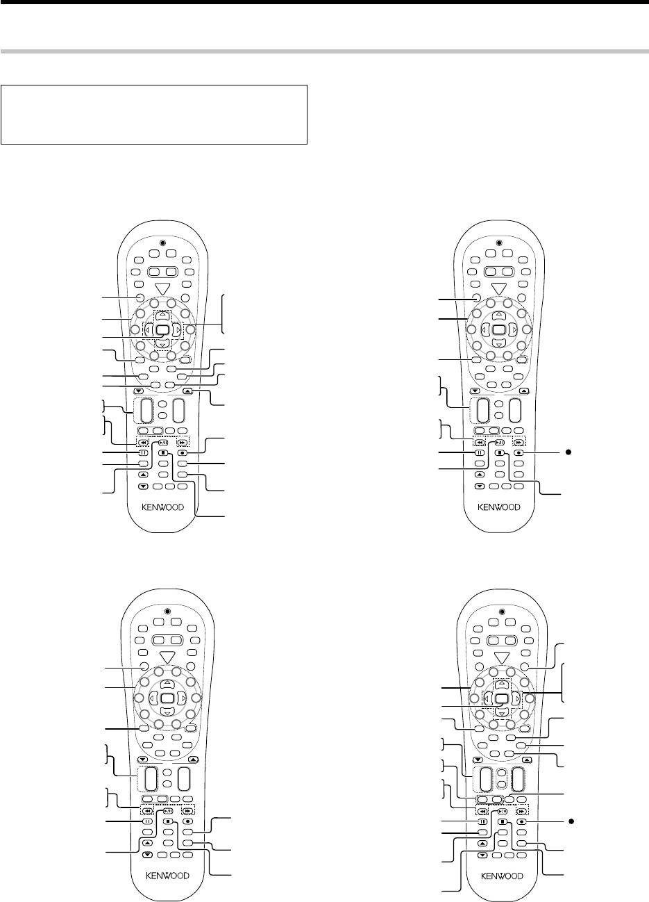
58 EN
Basic remote control operations for other components
+100 key
(Select tracks)
¢ (Skip up)
4 (Skip down)
33 (Search)
22 (Search)
3 (Play)
8 (Pause)
7 (Stop)
S
R
C
P
o
w
e
r
T
V
P
o
w
e
r
5
6
8
9
4
3
2
1
0
7
Dimmer
Tune –Tune +Band
Setup
Last
Top MenuAuto
Info
Listen Mode
Retern
Exit
Sound
Mute
TV
VOL
4
¢
VOL
+
–
CH
+
–
Menu
Sleep
Disc Skip
Input Sel.
Disk Sel.
OSD
Guide
Page
TV Mute
Angle
Audio Subtitle
+ 10+
100
Multi
Multi
P. Call
P. Call
Enter
GAME
RCV
Mode
POWER
RCVR
VID2
VID1
DVD
AUX
F.AUX
TUNER
Net
Mode
M.Card
Mode
–+
TV Input
TV
Stereo
Dolby
Vurtual
Active
EQ
Input
Mode
Remote
Setup
(Record)
SRC Power
(Source power)
Numeric keys/+10 key
(Select tracks)
Disc Sel.
(Select disc)
Disc Skip
(Select disc)
33 (Search)
22 (Search)
38 (Play/Pause)
8 (Pause)
7 (Stop)
S
R
C
P
o
w
e
r
T
V
P
o
w
e
r
5
6
8
9
4
3
2
1
0
7
Dimmer
Tune –Tune +Band
Setup
Last
Top MenuAuto
Info
Listen Mode
Retern
Exit
Sound
Mute
TV
VOL
4
¢
VOL
+
–
CH
+
–
Menu
Sleep
Disc Skip
Input Sel.
Disk Sel.
OSD
Guide
Page
TV Mute
Angle
Audio Subtitle
+ 10+
100
Multi
Multi
P. Call
P. Call
Enter
GAME
RCV
Mode
POWER
RCVR
VID2
VID1
DVD
AUX
F.AUX
TUNER
Net
Mode
M.Card
Mode
–+
TV Input
TV
Stereo
Dolby
Vurtual
Active
EQ
Input
Mode
Remote
Setup
¢ (Skip up)
4 (Skip down)
SRC Power
(Source power)
+100
(Select disds)
Numeric keys/+10 key
(Select tracks)
CD player operation keys
MD recorder operation keys (made by KENWOOD)
DVD player , MD recorder CD player & TV operations
Refer to the following for the type of remote control operations available for each component.
÷When pressing keys in succession, press each key firmly and be sure
to wait at least 1 second before pressing the next key.
÷Numeric keys function the same as the numeric keys on the original
remote.
1Select the input source.
2Press the keys corresponding to the operations you
desire. Refer to the following sections for details.
These keys can be used to perform the basic operations of KENWOOD and other manufacturers’ components which the setup code for each
component had been entered beforehand. uQ
DVD player operation keys
33 (Search)
22 (Search)
7 (Stop)
Menu
+100 key
(Select tracks)
Audio
Enter
Subtitle
S
R
C
P
o
w
e
r
T
V
P
o
w
e
r
5
6
8
9
4
3
2
1
0
7
Dimmer
Tune –Tune +Band
Setup
Last
Top MenuAuto
Info
Retern
Exit
Sound
Mute
TV
VOL
4
¢
VOL
+
–
CH
+
–
Menu
Sleep
Disc Skip
Input Sel.
Disk Sel.
OSD
Guide
Page
TV Mute
Angle
Audio Subtitle
+ 10+
100
Multi
Multi
P. Call
P. Call
Enter
GAME
RCV
Mode
POWER
RCVR
VID2
VID1
DVD
AUX
F.AUX
TUNER
Net
Mode
M.Card
Mode
–+
TV Input
TV
Stereo
Dolby
Vurtual
Active
EQ
Input
Mode
Remote
Setup
Return
%(Cursor up)
fi(Cursor down)
@(Cursor left)
#(Cursor right)
Listen Mode
8 (Pause)
3 (Play)
SRC Power
Angle
Disc Sel.
(Select discs)
Disc Skip
(Select discs)
Numeric keys/+10 key
(Select tracks)
¢ (Skip up)
4 (Skip down)
OSD
(On screen display)
Page 5/∞
(Page down or up)
Top Menu
(Title)
Numeric keys/+10 key
TV Input
(Record)
CH +/–
(Channel +/–)
TV VOL +/–
33 (Fast forward)
22 (Rewind)
7 (Stop)
Guide
Menu
TV Mute
Enter
Subtitle
S
R
C
P
o
w
e
r
T
V
P
o
w
e
r
5
6
8
9
4
3
2
1
0
7
Dimmer
Tune –Tune +Band
Setup
Last
Top MenuAuto
Info
Retern
Exit
Sound
Mute
TV
VOL
4
¢
VOL
+
–
CH
+
–
Menu
Sleep
Disc Skip
Input Sel.
Disk Sel.
OSD
Guide
Page
TV Mute
Angle
Audio Subtitle
+ 10+
100
Multi
Multi
P. Call
P. Call
Enter
GAME
RCV
Mode
POWER
RCVR
VID2
VID1
DVD
AUX
F.AUX
TUNER
Net
Mode
M.Card
Mode
–+
TV Input
TV
Stereo
Dolby
Vurtual
Active
EQ
Input
Mode
Remote
Setup
Exit
TV Power
% (Cursor up)
fi (Cursor down)
@ (Cursor left)
# (Cursor right)
Listen Mode
8 (Pause)
3 (Play)
Info
(Display)
Last
(Last channel)
TV operation keys
(including TVs incorporating VCR)
*5462/45-59/EN 04.4.13, 8:01 PM58
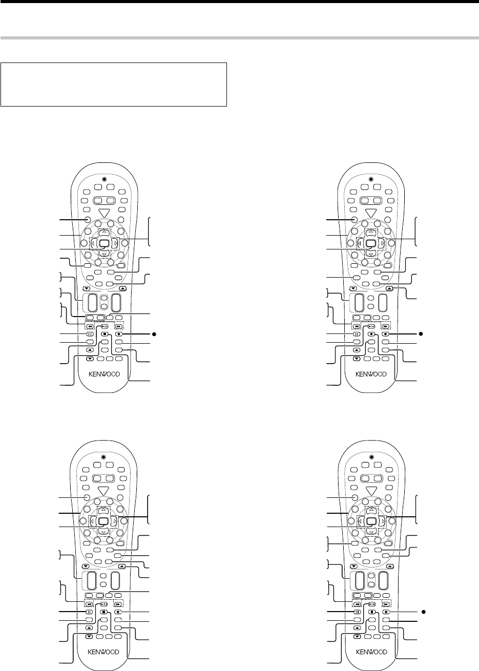
59 EN
Basic remote control operations for other components
Numeric keys
TV Input
(Record)
Last
(Last channel)
CH +/–
(Channel +/–)
TV VOL +/–
33 (Fast forward)
22 (Rewind)
7 (Stop)
Guide
Menu
TV Mute
Enter
Info
(Display)
S
R
C
P
o
w
e
r
T
V
P
o
w
e
r
5
6
8
9
4
3
2
1
0
7
Dimmer
Tune –Tune +Band
Setup
Last
Top MenuAuto
Info
Retern
Exit
Sound
Mute
TV
VOL
4
¢
VOL
+
–
CH
+
–
Menu
Sleep
Disc Skip
Input Sel.
Disk Sel.
OSD
Guide
Page
TV Mute
Angle
Audio Subtitle
+ 10+
100
Multi
Multi
P. Call
P. Call
Enter
GAME
RCV
Mode
POWER
RCVR
VID2
VID1
DVD
AUX
F.AUX
TUNER
Net
Mode
M.Card
Mode
–+
TV Input
TV
Stereo
Dolby
Vurtual
Active
EQ
Input
Mode
Remote
Setup
Exit
% (Cursor up)
fi (Cursor down)
@ (Cursor left)
# (Cursor right)
Listen Mode
8 (Pause)
3/8 (Play/Pause)
SRC Power
(Source power)
Input Sel.
(Input selection)
VCR operation keys
VCR , Satellite receiver & Cable converter operations
Refer to the following for the type of remote control operations available for each component.
÷When pressing keys in succession, press each key firmly and be sure
to wait at least 1 second before pressing the next key.
÷Numeric keys function the same as the numeric keys on the original
remote.
1Select the input source.
2Press the keys corresponding to the operations you
desire. Refer to the following sections for details.
These keys can be used to perform the basic operations of KENWOOD and other manufacturers’ components which the setup code for each
component had been entered beforehand. uQ
Guide
Menu
Enter
Audio
S
R
C
P
o
w
e
r
T
V
P
o
w
e
r
5
6
8
9
4
3
2
1
0
7
Dimmer
Tune –Tune +Band
Setup
Last
Top MenuAuto
Info
Retern
Exit
Sound
Mute
TV
VOL
4
¢
VOL
+
–
CH
+
–
Menu
Sleep
Disc Skip
Input Sel.
Disk Sel.
OSD
Guide
Page
TV Mute
Angle
Audio Subtitle
+ 10+
100
Multi
Multi
P. Call
P. Call
Enter
GAME
RCV
Mode
POWER
RCVR
VID2
VID1
DVD
AUX
F.AUX
TUNER
Net
Mode
M.Card
Mode
–+
TV Input
TV
Stereo
Dolby
Vurtual
Active
EQ
Input
Mode
Remote
Setup
Exit
Listen Mode
SRC Power
(Source power)
Numeric keys
CH +/–
(Channel +/–)
8 (Pause)
3 (Play)
Info
(Display)
% (Cursor up)
fi (Cursor down)
@ (Cursor left)
# (Cursor right)
Page 5/∞
(Page down or up)
(Record)
Input Sel.
(Input selection)
Last
(Last channel)
7 (Stop)
33
22
Numeric keys
TV Input
(Record)
Last
(Last channel)
Input Sel.
(Input selection)
CH +/–
(Channel +/–)
7 (Stop)
Guide
Menu
Enter
Info
(Information)
S
R
C
P
o
w
e
r
T
V
P
o
w
e
r
5
6
8
9
4
3
2
1
0
7
Dimmer
Tune –Tune +Band
Setup
Last
Top MenuAuto
Info
Retern
Exit
Sound
Mute
TV
VOL
4
¢
VOL
+
–
CH
+
–
Menu
Sleep
Disc Skip
Input Sel.
Disk Sel.
OSD
Guide
Page
TV Mute
Angle
Audio Subtitle
+ 10+
100
Multi
Multi
P. Call
P. Call
Enter
GAME
RCV
Mode
POWER
RCVR
VID2
VID1
DVD
AUX
F.AUX
TUNER
Net
Mode
M.Card
Mode
–+
TV Input
TV
Stereo
Dolby
Vurtual
Active
EQ
Input
Mode
Remote
Setup
Exit
% (Cursor up)
fi (Cursor down)
@ (Cursor left)
# (Cursor right)
Listen Mode
8 (Pause)
3 (Play)
Subtitle
Page 5/∞
(Page down or up)
SRC Power
(Source power)
33
22
Cable converter operation keys
Satellite receiver operation keys
CH +/–
(Channel +/–)
Menu
+100 key/
TV Mute
Enter
S
R
C
P
o
w
e
r
T
V
P
o
w
e
r
5
6
8
9
4
3
2
1
0
7
Dimmer
Tune –Tune +Band
Setup
Last
Top MenuAuto
Info
Retern
Exit
Sound
Mute
TV
VOL
4
¢
VOL
+
–
CH
+
–
Menu
Sleep
Disc Skip
Input Sel.
Disk Sel.
OSD
Guide
Page
TV Mute
Angle
Audio Subtitle
+ 10+
100
Multi
Multi
P. Call
P. Call
Enter
GAME
RCV
Mode
POWER
RCVR
VID2
VID1
DVD
AUX
F.AUX
TUNER
Net
Mode
M.Card
Mode
–+
TV Input
TV
Stereo
Dolby
Vurtual
Active
EQ
Input
Mode
Remote
Setup
Listen Mode
Subtitle
SRC Power
(Source power)
Numeric keys/+10 key
33
22
Exit
8 (Pause)
3/8 (Play/Pause) Last
(Last channel)
7 (Stop)
Info
(Display)
Input Sel.
(Input selection)
(Record)
% (Cursor up)
fi (Cursor down)
@ (Cursor left)
# (Cursor right)
Sirius operation keys (made by KENWOOD)
*5462/45-59/EN 04.4.13, 8:01 PM59

60 EN
In case of difficulty
Amplifier
Symptom
Resetting the Microcomputer
The microcomputer may malfunction (unit cannot be operated, or
shows an erroneous display) if the power cord is unplugged while
the power is ON, or due to some other external factor. If this
happens, execute the following procedure to reset the microcom-
puter and return the unit to its normal operating condition.
Unplug the power cord from the wall outlet, then plug it back in
while holding down the POWER ON/STANDBY (For U.S.A and
Canada) or ON/STANDBY key (For Europe and Australia).
÷Please note that resetting the microcomputer will clear the contents
of the memory and returns the unit to the state it was in when it left
the factory.
Remedy
No sound from the speakers.
Sound is not output from the speaker,
or their sound is very small.
The standby indicator blinks and sound
is not output.
The audio and video of a different
channel are output.
The video is not output.
Audio cannot be recorded.
A video source cannot be recorded
normally.
When playing a digital source signal,
the sound is cut off soon after it starts.
Dolby Digital or DTS audio software
cannot be played in multi-channel audio.
The audio of a satellite digital
broadcasting cannot be switched.
The input for the unit is set automatically
to "GAME" when the unit is turned ON.
÷Connect them properly referring to "Connecting the speakers"#
÷If muting is ON, release it. ⁄
÷If headphones are connected, disconnect them. º
÷Press the Input Mode key to select to full auto mode. 8
÷Check if the assignment of digital audio input jacks is correct. •
÷Connect them properly referring to "Connecting the speakers"#
÷See "Speaker settings" and check if the setting for all of the speakers is correct. ¢
÷Select a surround mode.
÷Adjust the speaker levels using the test tone. §
÷The protection circuitry is activated because speaker cords are short-circuited. Disconnect the
power cord from the AC wall outlet, switch the receiver OFF, remove the short-circuiting and turn
the receiver ON again.
÷The protection circuitry is activated because the output power is too high. Turn this unit OFF
then ON again and reduce the output volume level.
÷The protection circuitry activated due to extreme rise in temperature. Turn this unit OFF then
ON again and reduce the output volume level.
÷The protection circuitry is activated because the impedance of the speakers in use is lower
than specified. Use speakers of the specified impedance.
÷Check if the assignment of digital audio input jacks and component video jacks is correct. •
÷Connect the video source to be played to this unit and this unit to the monitor TV using the same
type of cords (Component video cords, S VIDEO cords or yellow RCA video cords) correctly. 0
÷Connect the equipment correctly by referring to "Connecting video components, audio
components" and "Digital connections". 0@
÷If it is the digital audio that you attempt to record, set up the unit correctly by referring to
"Recording music in REC mode". ¤
÷Copy-guarded video software cannot be recorded.
÷The S VIDEO and component video inputs cannot be recorded. Connect the video source to
the yellow RCA video jack. 0
÷There are many possible causes for this problem, depending on the type of player used.
Switch the input mode to DIGITAL MANUAL during playback of the digital source, and restart the
playback from the beginning. 8
÷Check if the digital output setting of the digital audio player is correct.
÷With certain broadcasting, the audio cannot be switched on the receiver. In this case, switch the
audio on your satellite digital tuner.
÷The GAME mode function is activated. ¶
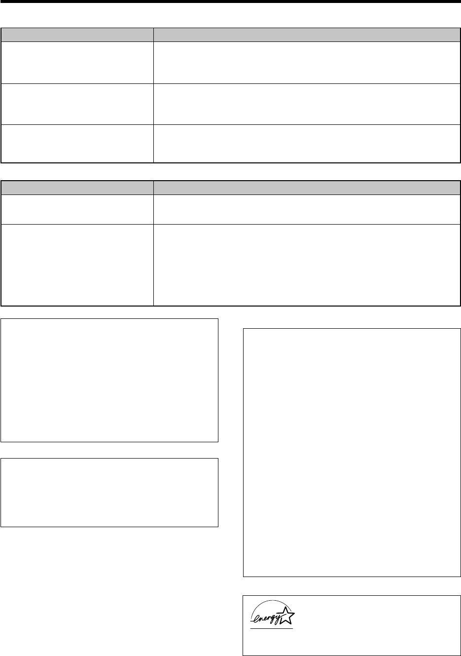
61 EN
In case of difficulty
÷Register its setup code correctly. t
÷Press the input selector key and select the optimum control mode.
÷Replace with new batteries.
÷Point the remote control unit to the remote sensor of the receiver. (
÷Connect them properly referring to "Setting up the system"
÷The remote control has not been set to the operation mode for the component you wish to
control. Press the source select keys or SRC Power key to activate the operation mode for the
component you want to control before operation. y
Control of another component is
impossible.
Remote control operation is not
possible.
Remote control unit
Symptom Remedy
Memory back-up function
If the power supply to the receiver is shut down for about a day
or more, the following settings will be reset to the initial condi-
tions. Please be careful.
÷Power mode = OFF
÷Volume level =
-
66 dB
÷Dimmer level = OFF (Brightest condition)
÷Broadcast band = FM
÷Frequency setting = 87.50 MHz
÷Tuning mode = AUTO
As an ENERGY STAR® Partner, Kenwood Corpora-
tion has determined that this products meets the
ENERGY STAR® guidelines for energy efficiency.
This product can save energy. Saving energy reduces
air pollution and lowers utility bills.
FCC WARNING
This equipment may generate or use radio frequency energy. Changes
or modifications to this equipment may cause harmful interference
unless the modifications are expressly approved in the instruction
manual. The user could lose the authority to operate this equipment
if an unauthorized change or modification is made.
NOTE:
This equipment has been tested and found to comply with the limits
for a Class B digital device, pursuant to Part 15 of the FCC Rules.
These limits are designed to provide reasonable protection against
harmful interference in a residential installation. This equipment may
cause harmful interference to radio communications, if it is not
installed and used in accordance with the instructions. However,
there is no guarantee that interference will not occur in a particular
installation. If this equipment does cause harmful interference to
radio or television reception, which can be determined by turning the
equipment off and on, the user is encouraged to try to correct the
interference by one or more of the following measures:
– –
Reorient or relocate the receiving antenna.
– –
Increase the separation between the equipment and receiver.
– –
Connect the equipment into an outlet on a circuit different from
that to which the receiver is connected.
– –
Consult the dealer or an experienced radio / TV technician for help.
For the U.S.A.
Note to CATV system installer
This reminder is provided to call the CATV system installer's attention
to Article 820-40 of the NEC that provides guidelines for proper
grounding and, in particular, specifies that the cable ground shall be
connected to the grounding system of the building, as close to the
point of cable entry as practical.
÷Connect an antenna properly. *
÷Set the broadcast band properly.
÷Tune the frequency of the desired station. ‹
÷Install the outdoor antenna away from the road.
÷Turn off the power to the appliance.
÷Install the receiver farther away from the TV.
÷Preset a station with a receivable frequency.
Radio stations cannot be received.
Interference.
A station which was preset cannot be
received by pressing the corresponding
numeric key.
Tuner
Symptom Remedy
For the U.S.A.
For the U.S.A.
*5462/60-64/EN 04.4.13, 8:02 PM61

62 EN
Specifications (For U.S.A., Canada and Australia)
AUDIO section
For U.S.A., and Canada
Rated power output during STEREO operation
Effective power output during STEREO operation ...
130 W + 130 W
(1 kHz, 10% T.H.D. at 6 Ω)
For Australia
Rated power output during STEREO operation
Rated power output during STEREO operation .. 100 W + 100 W
DIN/IEC (20 Hz ~ 20 kHz, 0.7% T.H.D. at 6 Ω )
Effective power output during STEREO operation ...
130 W + 130 W
(1 kHz, 10% T.H.D. at 6 Ω)
Effective power output during SURROUND operation
FRONT ................................................................... 100 W + 100 W
......................... (1 kHz, 0.5% T.H.D. at 6 Ω one channel driven)
FRONT ................................................................... 130 W + 130 W
(1 kHz, 10% T.H.D. at 6 Ω one channel driven)
CENTER ................................................................................ 100 W
(1 kHz, 0.5% T.H.D. at 6 Ω one channel driven)
CENTER ................................................................................ 130 W
(1 kHz, 10% T.H.D. at 6 Ω one channel driven)
SURROUND .......................................................... 100 W + 100 W
(1 kHz, 0.5% T.H.D. at 6 Ω one channel driven)
130 W + 130 W
(1 kHz, 10% T.H.D. at 6 Ω one channel driven)
SURROUND BACK/SUBWOOFER ..................................... 100 W
(1 kHz, 0.5% T.H.D. at 6 Ω one channel driven)
130 W
(1 kHz, 10% T.H.D. at 6 Ω one channel driven)
Total harmonic distortion .......................... 0.09% (1 kHz, 50 W, 6 Ω)
Frequency response
DIGITAL IN (DVD, VIDEO 1, VIDEO 2, AUX, GAME)
...... 10 Hz ~ 44 kHz, Sampling frequency 96kHz, +0 dB ~ –3.0 dB
Signal to noise ratio
DIGITAL IN (DVD, VIDEO 1, VIDEO 2, AUX, GAME) ........... 96 dB
Input sensitivity / impedance
LINE (DVD, VIDEO 1, VIDEO 2, AUX, FRONT AUX, GAME)
.............................................................................. 400 mV / 47 kΩ
Output level / impedance
REC OUT ................................................................ 400 mV / 1 kΩ
PRE OUT (SURROUND BACK) ..................................... 1 V / 1 kΩ
PRE OUT (SUBWOOFER) ............................................. 1 V / 1 kΩ
Tone control
BASS................................................................ ±10 dB (at 100 Hz)
TREBLE ............................................................ ±10 dB (at 10 kHz)
DIGITAL AUDIO section
Sampling frequency ...... 32 kHz, 44.1 kHz, 48 kHz,88.2 kHz, 96 kHz
Input level / impedance / wave length
Optical (VIDEO 1, AUX, GAME)
....................................... (–15 dBm ~ –24 dBm), 660 nm ±30 nm
Coaxial (DVD, VIDEO 2) ....................................... 0.5 Vp-p / 75 Ω
VIDEO section
Input sensitivity / impedance
Composite (DVD, VIDEO 1, VIDEO 2, FRONT AUX, GAME)
.................................................................................. 1 Vp-p / 75 Ω
S VIDEO (DVD, VIDEO 2) (For Austrslia)
Luminance signal ................................................ 1 Vp-p / 75 Ω
Chrominance signal ..................................... 0.286 Vp-p / 75 Ω
COMPONENT VIDEO (DVD, VIDEO 2) (For U.S.A. and Canada)
Luminance signal ................................................ 1 Vp-p / 75 Ω
CB/CR-signal .................................................. ±0.32 Vp-p / 75 Ω
Output level / impedance
Composite (VIDEO 1, MONITOR OUT) ................. 1 Vp-p / 75 Ω
S VIDEO (MONITOR OUT) (For Austrslia)
Luminance signal ................................................ 1 Vp-p / 75 Ω
Chrominance signal ..................................... 0.286 Vp-p / 75 Ω
COMPONENT VIDEO (MONITOR OUT) (For U.S.A. and Canada)
Luminance signal ................................................ 1 Vp-p / 75 Ω
CB/CR-signal .................................................. ±0.32 Vp-p / 75 Ω
FM tuner section
Tuning frequency range..................................... 87.5 MHz ~ 108 MHz
Usable sensitivity (MONO)
................... 1.3 µV (75 Ω)/ 13.2 dBf (75 kHz dev, SINAD 30 dB)
50 dB quieting sensitivity
STEREO .............................. 28 µV (75 Ω)/ 40.2 dBf (75 kHz dev)
Total harmonic distortion (1 kHz)
MONO.......................................................... 0.5% (71.2 dBf input)
STEREO ....................................................... 0.7% (71.2 dBf input)
Signal to noise ratio (1 kHz)
MONO........................................................ 75 dB (71.2 dBf input)
STEREO ..................................................... 68 dB (71.2 dBf input)
Selectivity (±400 kHz) ................................................................. 70 dB
Stereo separation (1 kHz) ........................................................... 40 dB
Frequency response (30 Hz ~ 15kHz) ..................... +0.5 dB, –3.0 dB
AM tuner section
Tuning frequency range
For U.S.A., and Canada .............................. 530 kHz ~ 1,700 kHz
For Australia ................................................ 531 kHz ~ 1,602 kHz
Usable sensitivity (30% mod, S/N 20 dB) ......... 16 µV / (600 µV/m)
Signal to noise ratio (30% mod, 400 Hz)
......................................................... 50 dB (60 dBµ V EMF input)
GENERAL
Power consumption .................................................................... 85 W
Dimensions ....................................................... W: 440 mm (17-5/16")
H: 079 mm (3-1/8")
D: 364 mm (14-5/16")
Weight (Net) ....................................................................4.4 kg (9.7 lb)
70 watts per channel minimum RMS, both channels driven,
at 8 Ω from 20 Hz to 20 kHz with no more than 0.7% total
harmonic distortion. (FTC)
Notes
1.KENWOOD follows a policy of continuous advancements in development. For this reason specifications may be changed without notice.
2.The full performance may not be exhibited in an extremely cold location (under a water-freezing temperature).
100 watts per channel minimum RMS, both channels driven,
at 6 Ω from 20 Hz to 20 kHz with no more than 0.7% total
harmonic distortion.
70 watts per channel minimum RMS, both channels driven,
at 8 Ω from 20 Hz to 20 kHz with no more than 0.7% total
harmonic distortion. (FTC)

63 EN
Specifications (For Europe)
AUDIO section
Rated power output during STEREO operation ...... 100 W + 100 W
DIN/IEC (20 Hz ~ 20 kHz, 0.7% T.H.D. at 6 Ω )
Effective power output during STEREO operation ..... 130 W + 130 W
(1 kHz, 10% T.H.D. at 6 Ω )
Effective power output during SURROUND operation
FRONT ................................................................... 100 W + 100 W
......................... (1 kHz, 0.5% T.H.D. at 6 Ω one channel driven)
FRONT ................................................................... 130 W + 130 W
(1 kHz, 10% T.H.D. at 6 Ω one channel driven)
CENTER ................................................................................ 100 W
(1 kHz, 0.5% T.H.D. at 6 Ω one channel driven)
CENTER ................................................................................ 130 W
(1 kHz, 10% T.H.D. at 6 Ω one channel driven)
SURROUND .......................................................... 100 W + 100 W
(1 kHz, 0.5% T.H.D. at 6 Ω one channel driven)
130 W + 130 W
(1 kHz, 10% T.H.D. at 6 Ω one channel driven)
SURROUND BACK/SUBWOOFER ..................................... 100 W
(1 kHz, 0.5% T.H.D. at 6 Ω one channel driven)
130 W
(1 kHz, 10% T.H.D. at 6 Ω one channel driven)
Total harmonic distortion .......................... 0.09% (1 kHz, 50 W, 6 Ω)
Frequency response
DIGITAL IN (DVD, VIDEO 1, VIDEO 2, AUX, GAME)
...... 10 Hz ~ 44 kHz, Sampling frequency 96kHz, +0 dB ~ –3.0 dB
Signal to noise ratio
DIGITAL IN (DVD, VIDEO 1, VIDEO 2, AUX, GAME) ........... 96 dB
Input sensitivity / impedance
LINE (DVD, VIDEO 1, VIDEO 2, AUX, FRONT AUX, GAME)
.............................................................................. 400 mV / 47 kΩ
Output level / impedance
REC OUT ................................................................ 400 mV / 1 kΩ
PRE OUT (SURROUND BACK) ..................................... 1 V / 1 kΩ
PRE OUT (SUBWOOFER) ............................................. 1 V / 1 kΩ
Tone control
BASS................................................................ ±10 dB (at 100 Hz)
TREBLE ............................................................ ±10 dB (at 10 kHz)
DIGITAL AUDIO section
Sampling frequency ...... 32 kHz, 44.1 kHz, 48 kHz,88.2 kHz, 96 kHz
Input level / impedance / wave length
Optical (VIDEO 1, AUX, GAME)
....................................... (–15 dBm ~ –24 dBm), 660 nm ±30 nm
Coaxial (DVD, VIDEO 2) ....................................... 0.5 Vp-p / 75 Ω
VIDEO section
Input sensitivity / impedance
Composite (DVD, VIDEO 1, VIDEO 2, FRONT AUX, GAME)
............................................................................... 1 Vp-p / 75 Ω
S VIDEO (DVD, VIDEO 2)
Luminance signal ................................................ 1 Vp-p / 75 Ω
Chrominance signal ..................................... 0.286 Vp-p / 75 Ω
Output level / impedance
Composite (VIDEO 1, MONITOR OUT)
............................................................................... 1 Vp-p / 75 Ω
S VIDEO (MONITOR OUT)
Luminance signal ................................................ 1 Vp-p / 75 Ω
Chrominance signal ..................................... 0.286 Vp-p / 75 Ω
FM tuner section
Tuning frequency range..................................... 87.5 MHz ~ 108 MHz
Usable sensitivity (DIN at 75 Ω)
MONO........................ 1.3 µV/ 13.2 dBf (40 kHz dev, S/N 26 dB)
STEREO ................ 45 µV/ 42.1 dBf (40 + 6 kHz dev, S/N 46 dB)
Total harmonic distortion (DIN at 1 kHz)
MONO.......................................................... 0.2% (71.2 dBf input)
STEREO ....................................................... 0.8% (71.2 dBf input)
Signal to noise ratio (DIN weighted at 1 kHz)
MONO........................................................ 65 dB (71.2 dBf input)
STEREO ..................................................... 60 dB (71.2 dBf input)
Selectivity (DIN ±300 kHz) .......................................................... 64 dB
Stereo separation (1 kHz) ........................................................... 36 dB
Frequency response (30 Hz ~ 15kHz) ..................... +0.5 dB, –3.0 dB
AM tuner section
Tuning frequency range..................................... 531 kHz ~ 1,602 kHz
Usable sensitivity (30% mod, S/N 20 dB) ......... 16 µV / (600 µV/m)
Signal to noise ratio (30% mod, 400 Hz)
......................................................... 50 dB (60 dBµ V EMF input)
GENERAL
Power consumption .................................................................... 85 W
Dimensions ....................................................... W: 440 mm (17-5/16")
H: 079 mm (3-1/8")
D: 364 mm (14-5/16")
Weight (Net) ....................................................................4.4 kg (9.7 lb)
Notes
1.KENWOOD follows a policy of continuous advancements in development. For this reason specifications may be changed without notice.
2.The full performance may not be exhibited in an extremely cold location (under a water-freezing temperature).

For your records
Record the serial number, found on the back of the unit, in the spaces
designated on the warranty card, and in the space provided below. Refer
to the model and serial numbers whenever you call upon your dealer for
information or service on this product.
Model__________________ Serial Number ________________________
*5462/60-64/EN 04.4.13, 8:02 PM64
