Keri Systems NXT_2D 4D_Controller_Installation_Guide_I NXT 2D And 4D Installation Guide Controller
User Manual: Keri Systems NXT-2D and NXT-4D Installation Guide Installation Guide
Open the PDF directly: View PDF ![]() .
.
Page Count: 6
NXT 2-D/4-D Controller
Installation Guide
Page 1 of 6 P/N: 01997-001 Rev. I
1.0 Wiring and Layout Diagrams
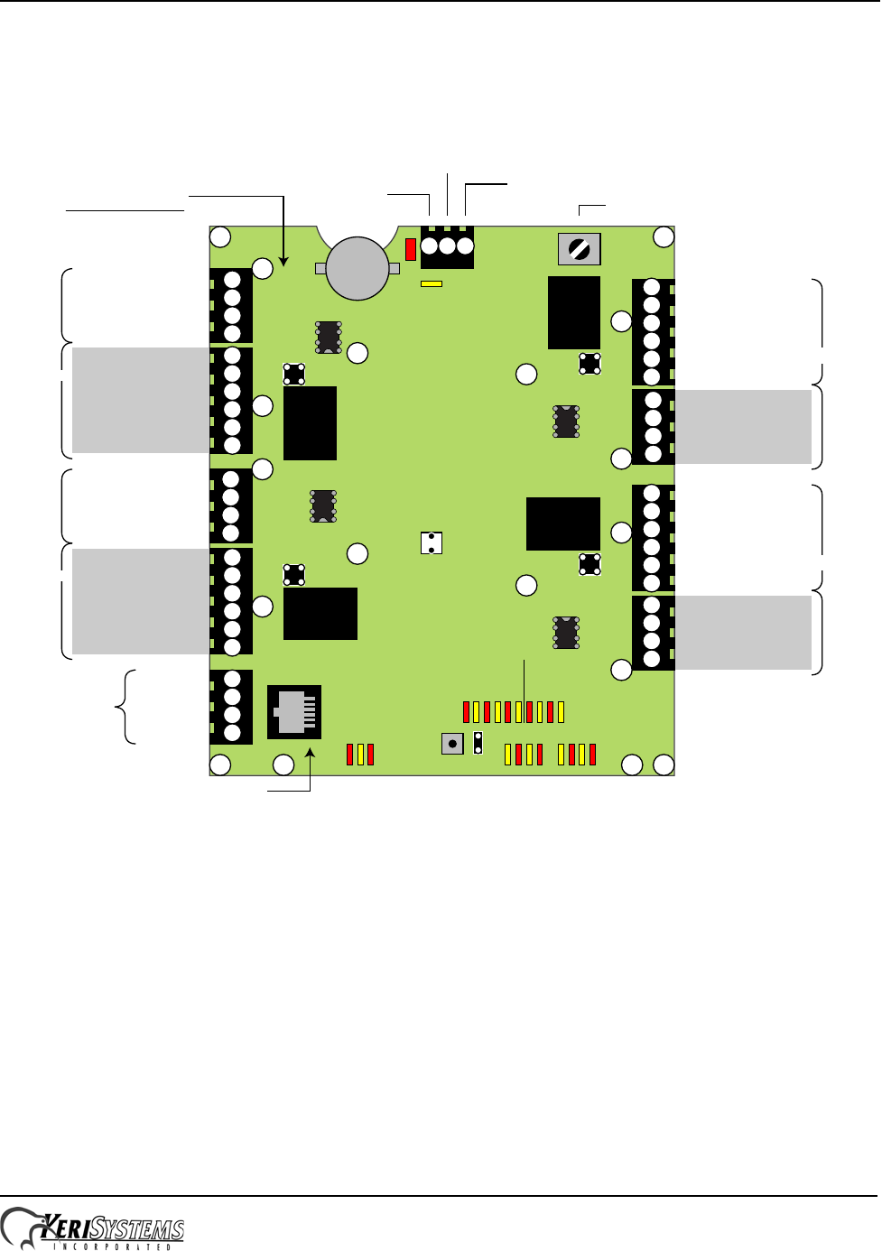
1.1 NXT-2D/-4D Controller
See Table 1 on page 2 for LED definitions.
NOTE: This equipment has been tested and found to comply with the limits for a Class A digital device, pursuant to Part 15 of the FCC Rules. These
limits are designed to provide reasonable protection against harmful interference when the equipment is operated in a commercial environment. This
equipment generates, uses, and can radiate radio frequency energy and, if not installed and used in accordance with the instruction manual, may cause
harmful interference to radio communications. Operation of this equipment in a residential area may cause harmful interference in which case the
owner will be required to correct the interference at the owner’s expense.
TB1
TB2
TB3
TB4
TB5
TB6
TB7
TB8
TB9
TB10
J2
J7
J8J9
J10
S1
TB5, TB6, TB7, TB8,
U34, U35, and Relays
ARE NOT INSTALLED
on 2-Door Controllers
J1
+12 VDC
Earth Ground
Power Ground
6
5
4
3
2
1
123
4
3
2
1
1
2
3
4
1
2
3
4
1
2
3
4
4
3
2
1
6
5
4
3
2
1
1
2
3
4
5
6
1
2
3
4
5
6
IO-Minus (White)
IO-Plus (Green)
Ground (Black)
+12 VDC (Red)
IO-Minus (White)
IO-Plus (Green)
Ground (Black)
+12 VDC (Red)
(Red) +12 VDC
(Black) Ground
(Green) IO-Plus
( White) IO-Minus
(Red) +12 VDC
(Black) Ground
(Green) IO-Plus
(White) IO-Minus
TX-Minus
TX-Plus
RX-Minus
RX-Plus
Ethernet RJ-45 Connection
Tamper
Switch
Bus 1
Bus 2
Bus 3
Bus 4
Ethernet
Direct Connection
J6
PCB Earth Ground Lug
P/N: 01997-002 - Rev. D
J3
RS-485
RS-485
RS-485
RS-485
Battery
abc
de f gh i
jklm nopq
r
s
NXT-2D/4D Installation Drawing
Relay
Relay
Relay
Relay
tuvw
U32 U33
U34
U35
NO - Relay
Common / Door Lock - Relay
NC - Relay
Door Switch - Input
Ground
REX - Input
NO - Relay
Common / Door Lock - Relay
NC - Relay
Door Switch - Input
Ground
REX - Input
REX - Input
Ground
Door Switch - Input
NC - Relay
Common / Door Lock - Relay
NO - Relay
REX - Input
Ground
Door Switch - Input
NC - Relay
Common / Door Lock - Relay
NO - Relay
Power LED
Thermal Fuse
LED
Ethernet
Activity LEDs
RS-485 Bus
Activity LEDs
Relay State
LEDs
Utility LEDs Overcurrent LEDs
Port 1
Port 2
Port 3
Port 4
NXT 2-D/4-D Controller
Installation Guide
Page 2 of 6 P/N: 01997-001 Rev. I
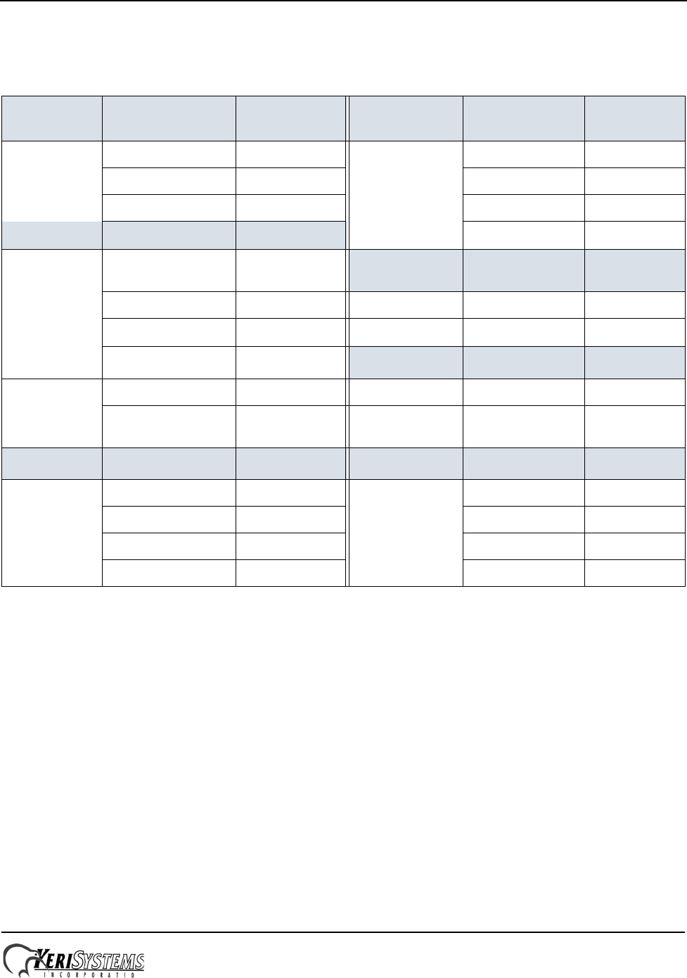
1.2 LED Definitions Table
Table 1: NXT Controller LEDs a
a. PCBs at revision F or greater have the RS-485 Bus Over Current LEDs t, u, v, and w. PCB revisions earlier
than revision F do NOT have these LEDs.
Ethernet
Comm Purpose LED Relay State Purpose LED
10/100 a (D21) Relay 1 active n (D3)
Link b (D22) Relay 2 active o (D8)
Activity c (D33) Relay 3 active p (D13)
Utility Purpose LED Relay 4 active q (D18)
Standard FW
Config Reset d (D48) Power Purpose LED
Host Channel Active e (D49) indicator r (D26)
Firmware Upgrade f (D50)
Event Channel Active g (D51) Thermal Fuse b
b. If LED s is green, the power wires are reversed; if LED s is red, the unit is drawing too much current.
Purpose LED
unused h (D52) indicator s (D23)
Mercury FW
Config Reset i (D53)
RS-485 Bus Purpose LED RS-485 Bus c
c. If LED t, u, v, or w is red, that individual bus is drawing too much current and the bus is shut down to protect
the controller. When this condition is corrected, the LED will turn off and the bus will be activated.
Purpose LED
Bus 1 Tx j (D1) Bus 1 Over Current t (D54)
Bus 2 Tx k (D6) Bus 2 Over Current u (D55)
Bus 3 Tx l (D11) Bus 3 Over Current v (D56)
Bus 4 Tx m (D16) Bus 4 Over Current w (D57)
NXT 2-D/4-D Controller
Installation Guide
Page 3 of 6 P/N: 01997-001 Rev. I
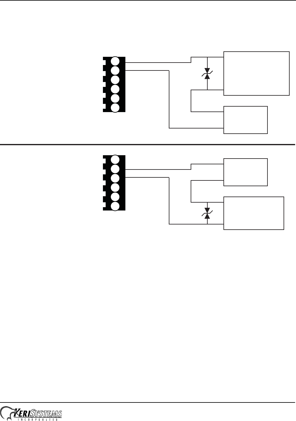
1.3 Port Protection
Transorbs are provided with the controller ship kit. They are used to protect the controller from voltage spikes induced on
the port wiring by absorbing the excess voltage and slowly releasing it back into the circuit. Keri strongly recommends
wiring in the transorbs provided with the controller ship kit. Refer to the Transorb Wiring Diagram below.
NOTE: The Transorbs that Keri provides are non-polar; they can be installed in either orientation.
1.4 Isolation Relays
For locking devices that may induce heavy voltage spikes – Mag Locks and devices with heavy-duty solenoids such as
turnstiles, vehicle gates, and overhead doors – Keri recommends using isolation relays. Keri has an Isolation Relay Kit
(p/n IRP-1). Please refer to the IRP-1 Isolation Relay Installation Guide (p/n 01833-001) for detailed information.
1
2
3
4
5
6
NO - Relay
Common - Lock / Alarm - Relay
NC - Relay
Door Switch - Input
Ground
REX - Input –
+
Power
Supply
Fail-Secure
Electric Lock Device
or
Alarm
–
+
1
2
3
4
5
6
NO - Relay
Common - Lock - Relay
NC - Relay
Door Switch - Input
Ground
REX - Input
–
+Power
Supply
Fail-Safe
Electric Lock
Device
–
+
Port
Terminal Block
Port
Terminal Block

NXT 2-D/4-D Controller
Installation Guide
Page 4 of 6 P/N: 01997-001 Rev. I
2.0 Specifications
2.1 NXT-2D/-4D Dimensions
• NXT Controller PCB
- 6.50 inches high by 5.50 inches wide by 1.00 inch deep, not including wiring connectors
- 16.51 cm by 13.97 cm by 2.54 cm
• NXT Enclosure
- 13.00 inches high by 10.5 inches wide by 3.00 inches deep
- 33.02 cm by 26.67 cm by 7.62 cm
2.2 Linear Power Supply Requirements
• 10 to 14 VDC @ 2.5 A (maximum current draw for a fully loaded NXT-2D/-4D controller)
2.3 Current Requirements at 12 VDC
• 650 mA max for an NXT-4D Controller
• 570 mA max for an NXT-2D Controller
• 250 mA max for each NXT-4x4
• 120 mA max for each NXT-1R, NXT-3R, NXT-4R, or NXT-5R Reader
• 115 mA max for each NXT-6RK Reader
• 100 mA max for each NXT-RM Reader Interface Module
NOTE: Keri recommends using separate power supplies for the controller and the electronic locking device (magnetic
lock, door strike, etc.). Only linear power supplies or Keri approved switching power supplies should be used for the
controller (refer to the Recommended Peripherals document – p/n 01924-001). Use isolation relays (Keri p/n IRP-1)
between the controller and the electronic locking device to prevent spikes or surges from the locking device from affecting
the controller.
2.4 Relay Contact Rating
• 1 A @ 24 VDC
2.5 Operating Conditions
• 32°F to 150°F (0°C to 60°C) – 0% to 90% Relative Humidity, non-condensing
2.6 Battery/Memory Retention
• 5-year lithium battery backup to support controller RAM and real-time clock
2.7 Cable Options
RS-485 bus runs can daisy-chain together an NXT-4x4 and NXT-Reader on one line. The total cable run distance should
be no more than 500 feet from the NXT controller for runs with 4x4s and no more than 1,000 feet for Reader-only runs.
Refer to Table 2 on page 5 and Table 3 on page 5.
NOTE: Cable resistance causes a drop in voltage at the end of long cable runs. Ensure the appropriate power and current
for your device is available at the device at the end of the cable run. Heavier gauge cable reduces this effect.
NOTE: Keri does not recommend hot-plugging a Reader, RIM, or 4x4 into an NXT controller.
Remove power from the controller prior to connecting these devices.
NXT 2-D/4-D Controller
Installation Guide
Page 5 of 6 P/N: 01997-001 Rev. I
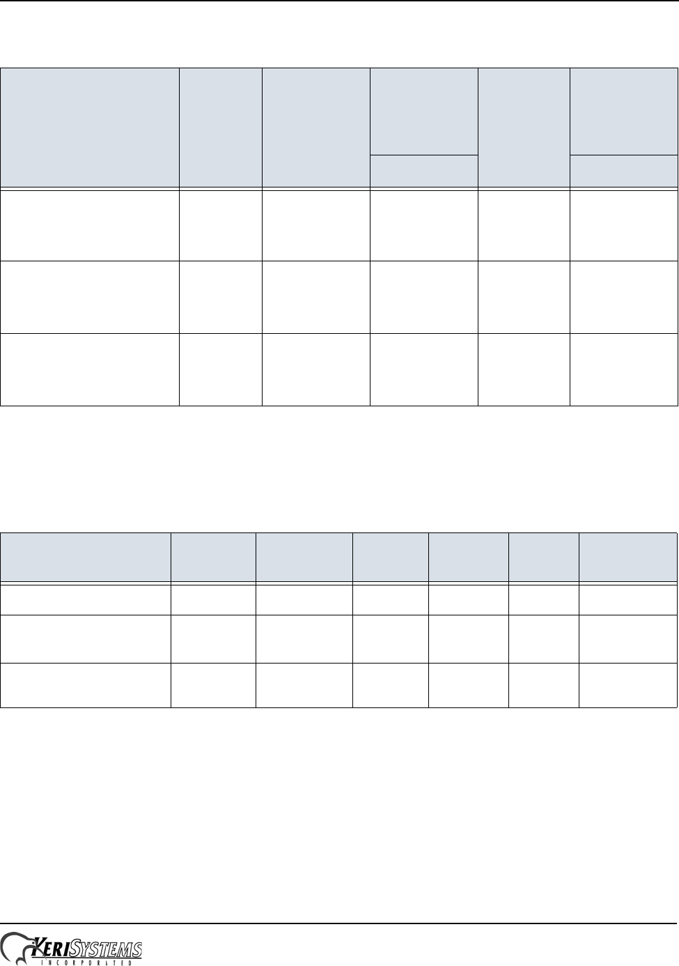
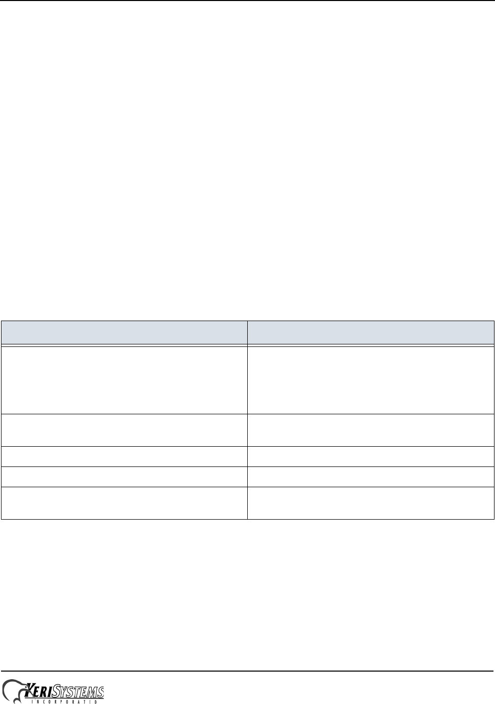
Table 2: Reader and 4x4 Cable Options
Connection Type Total Run
Length Minimum
AWG
Shielded,
Stranded,
2 Twisted-
Paira
a. Keri recommends this cable type for best system performance.
CAT-5b
b. Keri’s preferred low-cost option. Keri has no suggested vendor for this type of cable.
Shielded,
Stranded,
4-Conductorc
c. Use care when routing this type of cable as it can make the system more susceptible to EMI.
Suggest Suggest
RS-485 bus
from NXT-2D/-4D
to NXT-4x4 only
up to
500 feet 18 - Power
22 - Data Belden
8723 shielded Windy City:
414302-S
Tappan:
1880AB4M-CM
RS-485 bus
from NXT-2D/-4D
to NXT-4x4
and NXT Readers
up to
500 feet 18 - Power
22 - Data Belden
8723 shielded Windy City:
414302-S
Tappan:
1880AB4M-CM
RS-485 bus
from NXT-2D/-4D
to NXT Readers only
up to
1,000 feet 18 - Power
22 - Data Belden
8723 shielded Windy City:
416303-S
Tappan:
2280AB4M-CM
Table 3: Controller Power, Inputs, and Outputs Cable Requirements
Connection Total Run
Length # of
Conductors Shielded Stranded AWG Belden
Equivalent
controller power 250 feeta
a. To meet CE and C-tick regulations, the length of the controller power line can be no longer than
3 Meters (9.85 feet).
2 N Y 18 8461
earth ground shortest
pathb
b. Use the shortest possible path from earth ground point to PCB. Connect the earth ground only to the desig-
nated pin on the terminal block. This is important as all transient protection for the unit is made through this
earth ground connection. For unit protection, the earth ground connection should always be made first.
1 N N 18 no specific
requirement
inputs and outputsc
c. Values listed are minimums. Individual input and output devices may have more specific
requirements.
500 feet 2 N Y 22 no specific
requirement
NXT 2-D/4-D Controller
Installation Guide
Page 6 of 6 P/N: 01997-001 Rev. I
3.0 Resetting Controllers
Keri recommends resetting NXT controllers the first time these controllers are powered on. Also, under certain
circumstances NXT controllers may need to be reset.
NOTE: Resetting a standard NXT controller will restore the controller to a factory default state. It removes all network
configuration data assigned to the controller such as the IP Address, Subnet Mask, and Gateway address.
3.1 Reset a Standard NXT Controller
1. Remove power from the NXT controller.
2. Ensure a Jumper is across the J3 header (refer to the drawing on page 1). The Jumper can remain on J3 at all times.
3. Press the S1 switch and hold it down while applying power. Keep the button pressed until the Reset LED (D48) is lit.
This indicates the reset routine has begun. Once the LED is lit, the button can be released.
4. DO NOT REMOVE POWER FROM THE NXT CONTROLLER WHILE THE RESET LED IS LIT.
5. The Reset is complete when the Reset LED goes off.
3.2 Restore Configuration Information to a Reset Controller
1. In Doors.NET under Setup > Hardware Setup > Panels, click on the controller that was reset.
2. When the Communication field shows the controller is Online click the Update Network icon on the ribbon bar.
3. Click the Live Events tab and watch for the Update Network Completed event message. When this message is posted
the controller’s configuration information is restored.
4.0 Contact Keri Systems
End of document.
Keri USA Keri UK, Ireland, Europe
2305 Bering Drive
San Jose, CA 95131 Unit 17
Park Farm Industrial Estate
Ermine Street
Buntingford
Herts SG9 9AZ UK
Telephone: (800) 260-5265
(408) 435-8400 Telephone: + 44 (0) 1763 273 243
Fax: (408) 577-1792 Fax: + 44 (0) 1763 274 106
Web: www.kerisys.com Web: www.kerisystems.co.uk
E-mail: sales@kerisys.com
techsupport@kerisys.com E-mail: sales@kerisystems.co.uk
tech-support@kerisystems.co.uk
