Keri Systems Ip2000 SM 2000 Intelli Prox Quick Start Guide
User Manual: Keri Systems SM-2000 IntelliProx Quick Start Guide Product Guide
Open the PDF directly: View PDF ![]() .
.
Page Count: 10
- Contents
- 1.0 Features of the IntelliProx System
- 2.0 Specifications
- 3.0 Cautions
- 4.0 Jumper Settings
- 5.0 IntelliProx Connections in Stand-Alone Mode
- 6.0 IntelliProx Connections in 26-Bit Wiegand Reader Mode
- 7.0 Lock Connection Options
- 8.0 IntelliProx to D-Lite Connections
- 9.0 First Time Power On Procedure: PIN and Memory Reset, LED Mode
- 10.0 Standard Operation
- 11.0 Troubleshooting the IntelliProx
- 12.0 Ordering Information

IntelliProx – SM-2000
2305 Bering Drive 01830-003 Rev. H
San Jose, CA 95131 USA
(800) 260-5265 (408) 435-8400 FAX (408) 577-1792
Web: www.kerisys.com E-mail: sales@kerisys.com Page 1 of 10
IntelliProxQuick Start Guide
Contents
1. Features of the IntelliProxTM System
2. Specifications
3. Cautions
4. Jumper Settings
5. IntelliProx Connections in Stand-alone Mode
6. IntelliProx Connections in 26-Bit Wiegand Reader Mode
7. Lock Connection Options
8. IntelliProx to D-LiteTM Connections
9. First Time Power On Procedure: Pin and Memory Reset, LED Mode
10. Standard Operation
11. Troubleshooting the IntelliProx
12. Ordering Information
13. CE Declaration of Conformity
1.0 Features of the IntelliProx System
The IntelliProx is capable of operating as a stand-alone single-door entry control system or as a Wiegand output reader
with optional, back-up local door control. Small and unobtrusive, the IntelliProx can be mounted almost anywhere
within 500 feet of the reader (depending upon the type of reader and the maximum cable run allowed by that reader).
When used with a host controller, the IntelliProx can be mounted up to 500 feet from the host. Therefore, with the
appropriate reader, the reader to host distance can be as great as 1,000 feet.
1.1 Stand-alone Entry Control System
The IntelliProx has a capacity of 500 user cards, maintained in nonvolatile memory. The cards are held in "slots" within
the IntelliProx's internal memory. A Form-C relay output provides normally open and normally closed contacts for
door lock control. A door sense input provides door status for local annunciation if the door is held open. Programming
is accomplished using either D-Lite card database management software or the Keri Hand-Held Programmer (P/N:
HPP-22). With both the D-Lite program and the Hand-Held Programmer, access to the IntelliProx is controlled with
Personal Identification Numbers (PINs). A user must enter the PIN associated with the IntelliProx, and the PIN
associated with the host computer (when using D-Lite), before access to the IntelliProx unit is granted.
D-Lite is a simple, spreadsheet based IntelliProx slot/card management program that can enroll cards, upload a set of
cards to an IntelliProx unit, or download a set of cards from an IntelliProx unit. Refer to the D-Lite Users Manual for
programming instructions, P/N 01869-001. D-Lite can be used when the IntelliProx is used as a stand-alone entry
system; it is not compatible with the IntelliProx when the IntelliProx is used as a 26-bit Wiegand output reader.
Communication between a host computer (with the D-Lite program) and the IntelliProx unit is done through an RS-232
serial connection.
The Hand-Held Programmer works like a television remote-control unit, issuing commands to the IntelliProx with
simple two or three step push-button functions. Refer to the HPP-22 Quick Start Guide for programming instructions,
P/N 01831-003.

IntelliProx – SM-2000
2305 Bering Drive 01830-003 Rev. H
San Jose, CA 95131 USA
(800) 260-5265 (408) 435-8400 FAX (408) 577-1792
Web: www.kerisys.com E-mail: sales@kerisys.com Page 2 of 10
Quick Start GuideIntelliProx
1.2 Wiegand Output Reader
The IntelliProx has a standard 26-bit output, allowing reader data to be passed through to a host controller. The
IntelliProx's LED can be driven by two control lines or by a single control line to accommodate the host controller's
configuration. Optionally, the door lock control relay may be used for back-up local door control should the host
controller go down. An IntelliProx unit can be easily integrated with larger access systems relying on the host
controller's larger database, or it can be used in conjunction with the host database for alternative applications. Host
controllers that provide 5 to 12 VDC can power the IntelliProx.
NOTE: For proper Wiegand operation, KC26X, PKT26X, or MT96X credentials must be used.
1.3 RS-232 Output
The RS-232 serial connection used for D-Lite communication also transmits card read data. If the IntelliProx unit is in
stand-alone mode, Keri proximity card ID data is sent out the RS-232 serial data lines. If the IntelliProx unit is in
Wiegand Output mode, Wiegand card ID data is sent out the Data 0/Data 1 lines and the RS-232 serial data lines. A host
computer or access panel can use the RS-232 serial data lines as an alternative method for receiving card ID data from
the IntelliProx unit. Data is transmitted in an ASCII stream at 9600 baud with 8 data bits, 1 stop bit, and no parity.
However, when receiving data in this manner, the host computer or access panel cannot transmit data back to the
IntelliProx unit through the RS-232 serial data lines. Whenever the IntelliProx unit receives data through the RS-232
serial data lines, the IntelliProx unit assumes it should be in D-Lite communication mode and automatically switches to
D-Lite communication mode. When in D-Lite communication mode the IntelliProx unit’s LED fashes Red when the
first byte is received. The unit continues flashing Red and ignores card reads until the unit switches out of D-Lite mode
(done by a disconnect command from the D-Lite software or after 60 seconds of no communication).
2.0 Specifications
The IntelliProx system is made up of an SM-2000 smart module and a standard Keri Systems proximity reader.
Smart Module SM-2000 (see Figure 1):
Input Voltage 5 to 14 Volts DC
Current Consumption 50 mA, Nominal
Operating Temperature Range 0º to 65º Centigrade
User Capacity up to 500 Cards or Tags
Relay Contact Rating 1 Amp at 30 Volts DC or AC
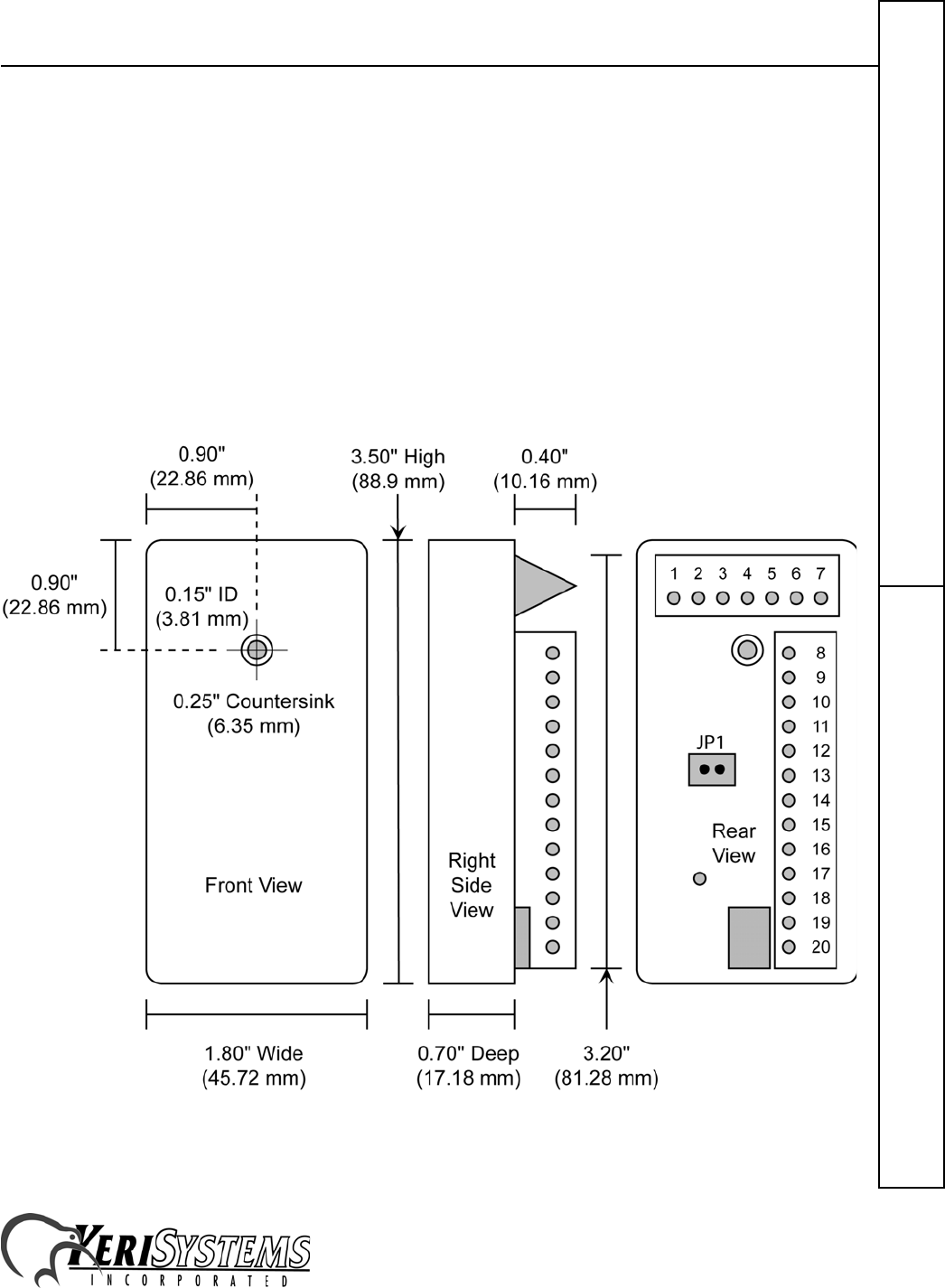
Dimensions 3.5" High x 1.8" Wide x 0.7" Deep (8.89 cm x 4.57 cm x 1.78 cm)
Weight 5 Ounces (0.14 kg)
Door Unlock Time 7 Seconds (factory default cannot be changed)
Door Held Open Time 7 Seconds (factory default cannot be changed)
SM-2000 plus Reader (refer to the appropriate Reader Quick Start Guide):
Current Consumption with Readers
IP-2003/-2004 100 mA, Typical (MS-3000/MS-4000 Reader)
IP-2005 150 mA, Typical (MS-5000 Reader)
IP-2007 250 mA, Typical (MS-7000 Reader)1
1. If the host controller provides 5 VDC reader power, the MS-7000 reader should be powered by a separate
power supply to ensure they have enough power for proper operation
IntelliProx – SM-2000
2305 Bering Drive 01830-003 Rev. H
San Jose, CA 95131 USA
(800) 260-5265 (408) 435-8400 FAX (408) 577-1792
Web: www.kerisys.com E-mail: sales@kerisys.com Page 3 of 10
IntelliProxQuick Start Guide
3.0 Cautions
An IntelliProx must have clean power to ensure best operating conditions. Regulated, linear power supplies are
recommended. Switching power supplies and rectified AC power supplies cannot be used as they are known sources for
radiated electromagnetic interference that affects IntelliProx operation.
When using the IntelliProx in place of standard proximity readers ensure that Keri KC-26 (or compatible) 26-bit cards
are used. The use of alternate format cards will not output a proper 26-bit identification number to the host system,
making card enrollment difficult if not impossible.
A jumper is available for resetting the IntelliProx's PIN and memory. The IntelliProx will not operate if JP1 is
installed; JP1 must be removed for normal system operation. If JP1 is installed and power is applied to the IntelliProx,
the PINs are reset to the factory default values and to the Dual-Line LED control configuration. If power is applied
again with JP1 still installed, all information in system memory is erased and cannot be recovered unless it had been
previously uploaded to a data file stored by the D-Lite program.
Figure 1: The IntelliProx SM-2000
IntelliProx – SM-2000
2305 Bering Drive 01830-003 Rev. H
San Jose, CA 95131 USA
(800) 260-5265 (408) 435-8400 FAX (408) 577-1792
Web: www.kerisys.com E-mail: sales@kerisys.com Page 4 of 10
Quick Start GuideIntelliProx
4.0 Jumper Settings
There are no switches or jumpers required for normal operation. JP1 is used only for clearing the IntelliProx's PIN and
system memory (see Figure 1). This should be done the first time the IntelliProx is powered on, prior to entering slot/
card data, to remove any spurious information that may be in the IntelliProx's database. Once the database is cleared,
any information that was in the database is erased and can only be recovered if the database had been saved using the D-
Lite program. JP1 must be removed for normal system operation. Refer to Section 9 - First Time Power On Procedure:
Pin and Memory Reset, LED Mode for instructions.
5.0 IntelliProx Connections in Stand-Alone Mode
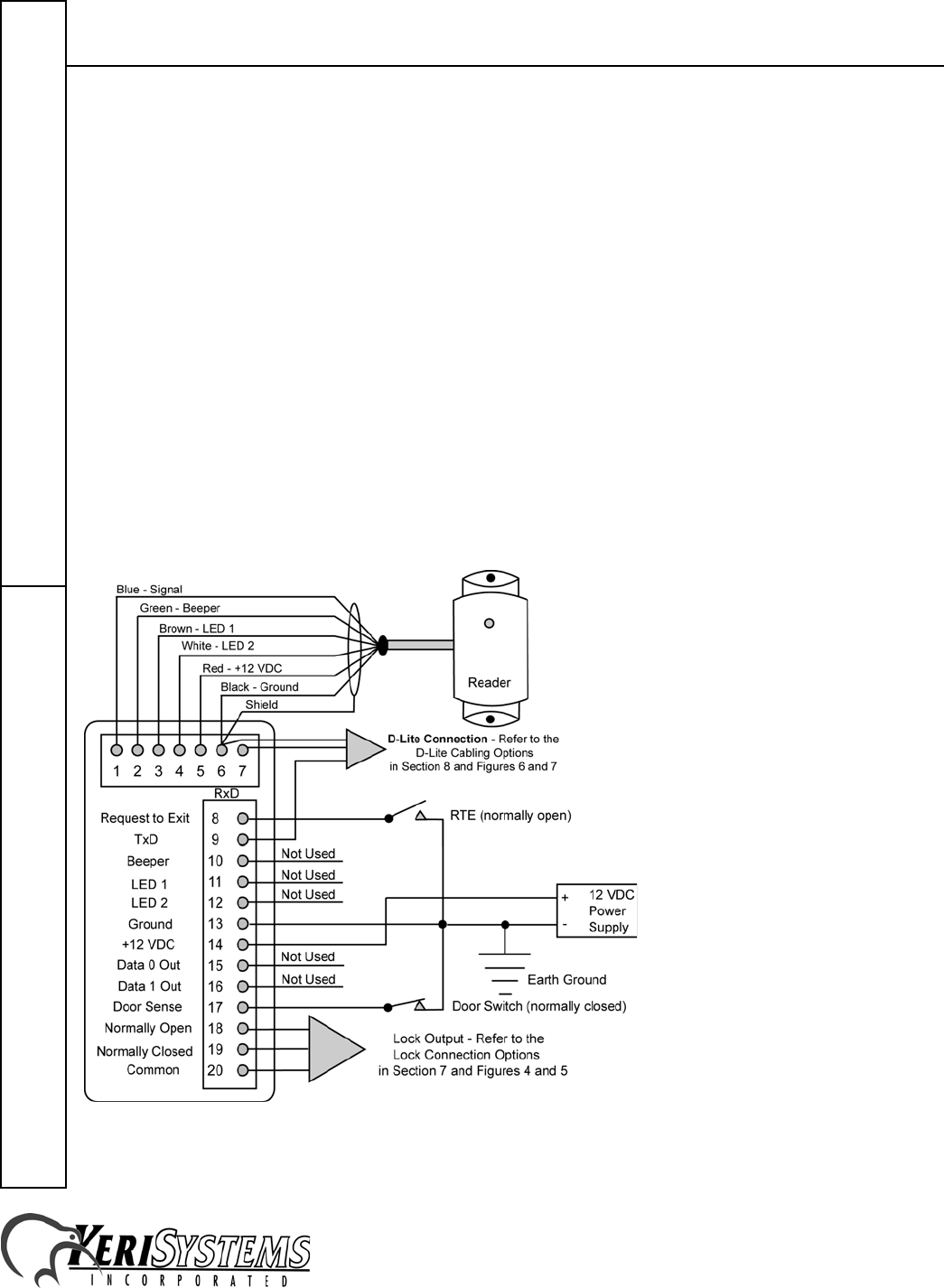
When connecting the IntelliProx unit (see Figure 2):
• There must be a quality earth ground connected to either the negative terminal of the power supply or to Pin-13 of
the IntelliProx.
• When wiring the reader to the IntelliProx, connect the reader cable's shield wire to Pin-6.
• For best operating conditions, attach a transient suppression device (such as a 1.5KE39C transorb or a Keri
Systems Isolation Relay, p/n IRP-1) across the power lines of the electric lock device.
• A door contact switch (normally closed) can be used to indicate the status of the door - open or closed. If a door
contact switch is not used, a jumper must be attached between Pin-17 (Door Sense Input) and Pin-13 (Ground).
• A request to exit (RTE) switch (normally open) can be used to indicate if a request to exit through a secure door has
been made. When the IntelliProx receives an RTE signal the door is unlocked to allow exit.
Figure 2: Stand-Alone Controller Mode Connections
IntelliProx – SM-2000
2305 Bering Drive 01830-003 Rev. H
San Jose, CA 95131 USA
(800) 260-5265 (408) 435-8400 FAX (408) 577-1792
Web: www.kerisys.com E-mail: sales@kerisys.com Page 5 of 10
IntelliProxQuick Start Guide
6.0 IntelliProx Connections in 26-Bit Wiegand Reader Mode
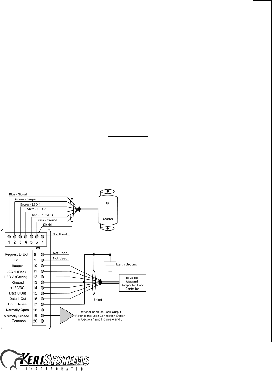
When connecting the IntelliProx unit (see Figure 3):
• KC26X, PKT26X, or MT26X credentials must be used for proper Wiegand operation.
• There must be a quality earth ground connected to either the negative terminal of the power supply or to Pin-13 of
the IntelliProx.
• Power for the IntelliProx may be provided by the host controller or by a separate power supply. If the IntelliProx
is powered by a separate power supply, ensure the grounds for the IntelliProx and the host controller are connected
to provide a common ground reference for Wiegand data.
• When wiring the reader to the IntelliProx, connect the reader cable's shield wire to Pin-6.
• For best operating conditions if the lock relay is used to provide optional back-up door control, attach a transient
suppression device (such as a 1.5KE39C transorb or a Keri Systems Isolation Relay, p/n IRP-1) across the power
lines of the electric lock device.
• A jumper must be attached between Pin-17 (Door Sense Input) and Pin-13 (Ground).
• Except for a quick BEEP and LED flash when a card or tag is presented, the host controller is responsible for
driving the beeper and the LED.
• The LED display mode may be programmed for either 2-line operation or 1-line operation. Instructions for setting
the LED display mode are found in section 10, Standard Operation.
- In 2-line operation, grounding the LED 1 signal (Pin 11) changes the reader's LED from Amber to Green and
grounding the LED 2 signal (Pin 12) changes the reader's LED from Amber to Red.
- In 1-line operation the LED 1 signal is not used. If the LED 2 signal is high, the reader's LED is Red. If it is
low, the reader's LED is Green. If it is toggling at 1 kHz, the reader's LED is Amber.
• To use the IP as a backup door controller (one that continues to control a door if the host controller is offline) you
must enroll cards into the IntelliProx using either an HPP-22 or the D-Lite software package. These cards would
only be used when the host controller is offline.
Figure 3: 26-Bit Wiegand Reader Mode Connections
IntelliProx – SM-2000
2305 Bering Drive 01830-003 Rev. H
San Jose, CA 95131 USA
(800) 260-5265 (408) 435-8400 FAX (408) 577-1792
Web: www.kerisys.com E-mail: sales@kerisys.com Page 6 of 10
Quick Start GuideIntelliProx
7.0 Lock Connection Options
When installing a door lock there are two things to consider: safety versus security, or should the door lock be "fail-
safe" or "fail-secure”.
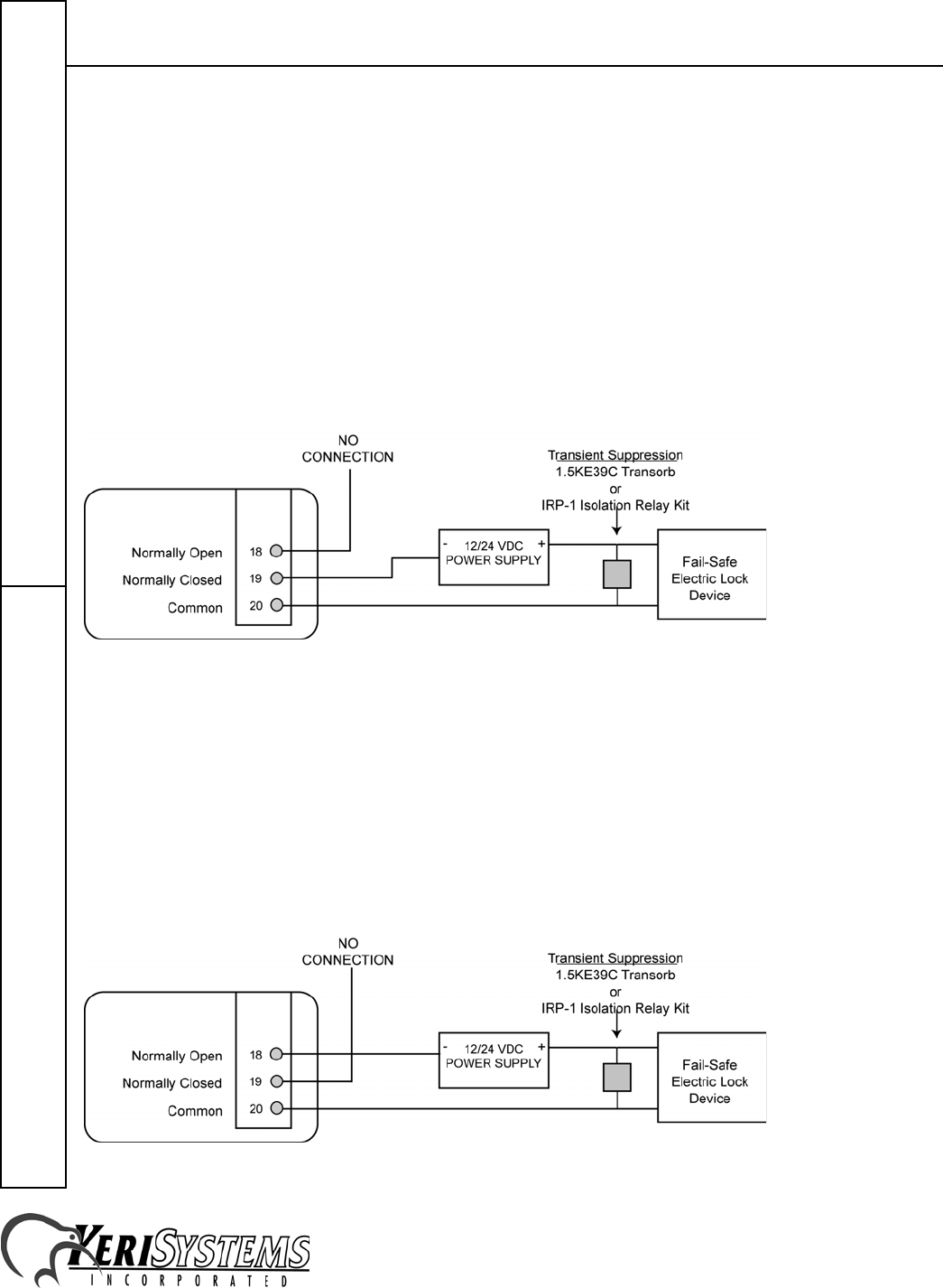
7.1 Fail-Safe Door Lock
Fail-safe means that if the power should fail at a door (perhaps due to a power outage or equipment failure), the door
will automatically unlock allowing entrance or egress. Power is required to keep the door locked. A fail-safe door
ensures people will be able to enter and exit through that door in the case of an emergency. A typical fail-safe
application may use a magnetic lock. In this application, the controller energizes the lock relay causing the lock relay to
open, breaking the power to the magnetic lock, and allowing the door to be opened. Refer to Figure 4 for a sample
wiring diagram.
NOTE: DO NOT share the 24VDC Lock Power Supply with the IntelliProx unit.
Figure 4: Sample Fail-Safe Wiring Diagrams
7.2 Fail-Secure Door Lock
Fail-secure means that if the power should fail at a door (perhaps due to a power outage or equipment failure), the door
will automatically lock and not allow entrance but can continue to allow egress if a mechanical override device is
present. Power is required to unlock the door. A fail-secure door ensures a secure area remains secure regardless of the
situation. A typical fail-secure application may use a door strike. In this application, the controller energizes the lock
relay, causing the lock relay to close, providing power to the release mechanism on the door strike, and allowing the
door to be opened. Refer to Figure 5 for a sample wiring diagram.
NOTE: DO NOT share the 24VDC Lock Power Supply with the IntelliProx unit.
Figure 5: Sample Fail-Secure Wiring Diagrams
IntelliProx – SM-2000
2305 Bering Drive 01830-003 Rev. H
San Jose, CA 95131 USA
(800) 260-5265 (408) 435-8400 FAX (408) 577-1792
Web: www.kerisys.com E-mail: sales@kerisys.com Page 7 of 10
IntelliProxQuick Start Guide
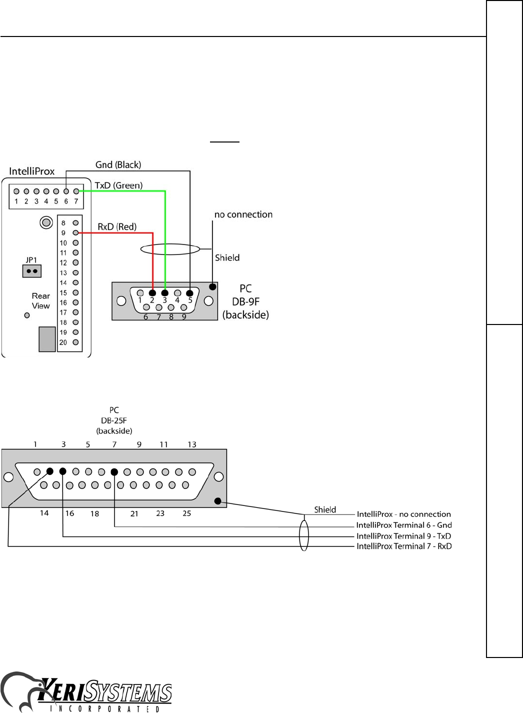
8.0 IntelliProx to D-Lite Connections
Communication between the IntelliProx and the D-Lite software is done between the RS-232 serial port in the
IntelliProx and a serial port in the host computer. The most common connection is made through a three-conductor,
shielded cable using a DB-9F connector to connect to the host computer. Some computers might use a DB-25F
connector. Refer to Figures 6 and 7 as appropriate for the computer you are using.
NOTE: Wire colors may be differenet than shown. Always verify pin to pin connections.
Figure 6: IntelliProx to DB-9F Connection
Figure 7: IntelliProx to DB-25F Connection
NOTE: Keri Systems does not supply the IntelliProx to DB-25F cable.

IntelliProx – SM-2000
2305 Bering Drive 01830-003 Rev. H
San Jose, CA 95131 USA
(800) 260-5265 (408) 435-8400 FAX (408) 577-1792
Web: www.kerisys.com E-mail: sales@kerisys.com Page 8 of 10
Quick Start GuideIntelliProx
9.0 First Time Power On Procedure: PIN and Memory Reset, LED
Mode
Before powering on an IntelliProx for the first time, its system memory must be cleared. This removes any spurious
information that may be in the IntelliProx's database. This will also reset the IntelliProx's PINs to the factory default
values: "1234" for the IntelliProx and "0000" for the host computer (for use with D-Lite).
9.1 To Reset the PINs to the Default Values
1. Ensure the IntelliProx power is OFF.
2. Install JP1 (see Figure 1).
3. Turn the IntelliProx power ON. If the original PINs are not at the factory default values, they are changed to the
default values, the reader's LED is steady Green and the beeper is beeping. If the original PINs are at the default
values, the reader's LED is steady Red and the beeper is beeping.
4. Turn the IntelliProx power OFF.
5. Remove JP1. The IntelliProx's PINs are now at the default values of "1234" for the IntelliProx and "0000" for the
host computer (for use with D-Lite).
NOTE: If JP1 is removed before the power is turned OFF, not only will the PINs be returned to the factory default
values, but also the IntelliProx's database is cleared.
9.2 To Clear Unit Memory
Ensure the IntelliProx power is OFF.
1. Install JP1 (see Figure 1).
2. Turn the IntelliProx power ON.
3. If the original PINs are not at the default values, they are changed to the default values, the reader's LED is steady
Green, and the beeper is beeping. Turn the IntelliProx's power OFF and then ON again. The IntelliProx's PINs are
now set to the default values of "1234" for the IntelliProx and "0000" for the host computer (for use with D-Lite).
4. If the original PINs are at the default values, the reader's LED is steady Red, the beeper is beeping, and the
IntelliProx is ready for the memory to be cleared.
5. With the power ON, the reader's LED blinking Red, and the beeper beeping remove JP1. The IntelliProx's memory
is cleared and the IntelliProx is ready for programming.
From this point on, JP1 should never be installed on the IntelliProx unless it is necessary to reset the PINs, or clear
system memory and rebuild its database from scratch. Applying power with JP1 installed irretrievably resets the PIN.
Applying power a second time and removing JP1 irretrievably erases all card holder data. A database can be restored if
the database has been saved using the D-Lite program prior to being cleared.
9.3 Setting LED Single-line or Dual-line Operation
LED line operating mode is set using a Keri Systems proximity card programmed with a unique card value (Keri
Systems P/N: 05509-401). The operating mode toggles from its current state to the other state every time the reader
reads the LED Operating Mode card. For example, if the IntelliProx is in single-line LED operating mode, presenting
the LED Operating Mode card will toggle the IntelliProx's to dual-line LED operating mode.
On power-up, the IntelliProx will beep twice and its LED will blink Red when in single-line mode, and it will beep
twice and its LED will blink Green when in dual-line mode.

IntelliProx – SM-2000
2305 Bering Drive 01830-003 Rev. H
San Jose, CA 95131 USA
(800) 260-5265 (408) 435-8400 FAX (408) 577-1792
Web: www.kerisys.com E-mail: sales@kerisys.com Page 9 of 10
IntelliProxQuick Start Guide
If no signal lines are connected to pins 11 and 12 of the IntelliProx to control the operation of the LEDs, the steady state
color when waiting for a card will be Red when in 1-line LED operating mode and Amber when in 2-line LED
operating mode.
10.0 Standard Operation
10.1 As a Wiegand Reader
When the IntelliProx is used as a Wiegand reader, the host controller is responsible for driving the beeper and the LED.
When a card or tag is presented to the reader, the IntelliProx will send a quick BEEP and an LED flash to acknowledge
the card has been read. The host controller then drives the beeper and LED's responses to the card/tag presentation.
10.2 As a Stand-alone Reader
The reader's LED will reflect the IntelliProx's operating status as follows.
The reader's beeper will reflect the IntelliProx's operating status as follows.
10.3 When in Programming Mode with the HPP-22
When the HPP-22 is being used to enter cardholder information, the IntelliProx cannot handle door access requests and
cannot communicate with the host computer/D-Lite program.
10.4 When in Programming Mode with the D-Lite Program
When D-Lite is being used to upload or download cardholder database information, the IntelliProx can handle door
access requests, but cannot receive commands from an HPP-22.
Color State Meaning
Amber Steady On Power On – Normal
Operation
Green Single Flash Valid Card Presented
Red Single Flash Invalid Card or Access
Denied
Tone Meaning
Short BEEP Valid Card Read
Continuous Beeping Alarm Condition
IntelliProx – SM-2000
2305 Bering Drive 01830-003 Rev. H
San Jose, CA 95131 USA
(800) 260-5265 (408) 435-8400 FAX (408) 577-1792
Web: www.kerisys.com E-mail: sales@kerisys.com Page 10 of 10
Quick Start GuideIntelliProx
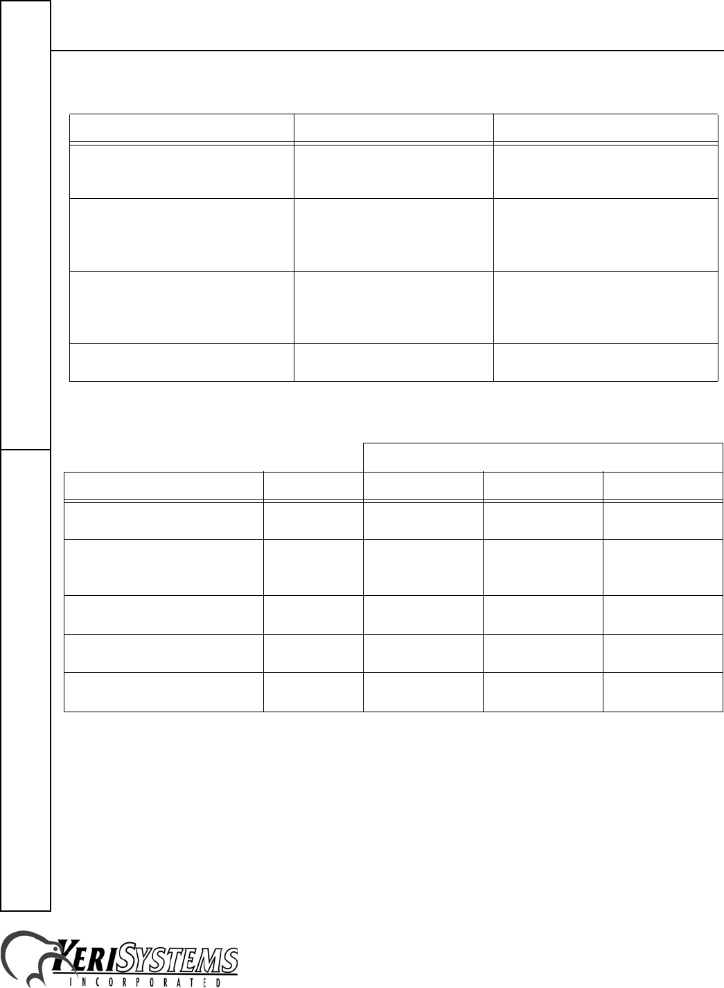
11.0 Troubleshooting the IntelliProx
12.0 Ordering Information
NOTE: Due to the physical size difference between cards and tags, tags provide approximately 50% less read range
than cards.
Problem Probable Cause Corrective Action
When a valid card is presented and the
door is opened, the Reader BEEPs
continually.
The door switch is not connected
or is not being used. Connect the door switch or install a
jumper across Pins 13 and 17.
The IntelliProx is not granting access
to any card. JP1 is installed. Turn power OFF and remove JP1.
NOTE: Your card database and PIN
are may be erased and may have to be
restored.
When using the IntelliProx for
optional back-up door control, a card
continues to have access after being
voided from the host system.
The card is still enrolled in the
IntelliProx database. Delete the card from the IntelliProx.
IntelliProx LED not lit RS–232 communication line
interrupted. Verify communication line is
functioning properly.
Reader Range
Model P/N at 5 VDC at 12 VDC at 24 VDC
IntelliProx
Smart Module SM–2000 – – –
IntelliProx + MicroStar
Door Frame Mullion Mount
Reader
IP–2003 up to 3 inches
(7.6 cm) up to 4 inches
(10.2 cm) –
IntelliProx + ShootingStar
Vandal Resistant Reader IP–2004 up to 1 inch
(2.5 cm) up to 1 inch
(2.5 cm) –
IntelliProx + MiniStar
Wall Switch Mount Reader IP–2005 up to 4 inches
(10.2 cm) up to 6 inches
(15.2 cm) –
IntelliProx + SuperStar
Medium Range Reader IP–2007 – up to 14 inches
(35.5 cm) –
