Kettler Riga 07042 700 Users Manual 7042+43 900 1064m 0210
07042-700 to the manual d45f5d99-ec94-43ff-8b83-eb8c89bd9264
2015-02-02
: Kettler Kettler-Riga-07042-700-Users-Manual-434851 kettler-riga-07042-700-users-manual-434851 kettler pdf
Open the PDF directly: View PDF ![]() .
.
Page Count: 17
Montageanleitung Tischtennistische
„RIGA“ und „RIGA PRO“
Art.-Nr. 07042-700, 07043-700, 07042-900, 07043-900
Der Umwelt zuliebe: Wir drucken auf 100% Altpapier!
F
D
GB
NL
E
I
PL

3
Assembly Instructions
Before assembling or using the table-tennis table, please read the following instructions carefully. They contain impor-
tant information for use and maintenance of the equipment as well as for your personal safety. Keep these instructions
in a safe place for maintenance purposes or for ordering spare parts.
All KETTLER products are designed in accordance with the latest safety regulations and undergo a constant process of quality control
during manufacturing. The knowledge gained in this process is used to constantly improve and develop our products. In order to offer
our customers the very best in product quality, we reserve the right to make technical changes at any time. In spite of this, should you
have any cause for complaint, please contact your KETTLER dealer.
GB
Note on Safety
■The table-tennis table should be used only for its intended pur-
pose, i.e. for playing with suitable table-tennis bats and balls.
■All other uses are prohibited and may be dangerous. The man-
ufacturer cannot be held liable for damage or injury caused by
improper use of the table.
■Damaged or worn components may endanger your safety or
shorten the lifespan of the table-tennis table. Replace worn or
damaged components immediately and remove the table from
use until this has been done. Use only spare parts manufactured
by KETTLER.
■The table-tennis table complies with all safety regulations. In-
correct repairs, alterations to the design (removal of original
parts, addition of other components etc.) may endanger the
safety of the user.
■Instruct other persons (in particular children) using the table in
its correct use, and draw their attention to any potential source
of danger, especially when setting up or dismantling the table.
■When setting up or dismantling the table, stay clear of its fold-
ing radius.
■When folded up, the table-tennis table presents a large surface
to the wind. For this reason, ensure that it is stored in a shel-
tered position.
■The table-tennis table may be pushed only into the transport po-
sition because there is otherwise a danger of injury.
■The unit complies with the standard EN 14468–1:2004.
■Depending on frequency of use, check all screws, bolts etc. reg-
ularly to ensure that they are in good condition.
■Caution: While assembly of the product keep off children’s
reach (Choking hazard - contains small parts).
■In case of enquiry, please contact your KETTLER dealer.
Handling the equipment
■Do not use the table-tennis table until it has been fully and cor-
rectly assembled and checked.
■Ensure that table-tennis tables which are not weatherproof are
not exposed to dampness or rain. Keep them well away from
direct sources of heat. Should the surface become warped, lay
the table on a level surface for a few days.
■Set the table up on a level surface.
■Do not cover it with plastic foil, under which condensation may
form. We recommend the weatherproof KETTLER tarpaulin, art.
no. 07032-000.
■For practising without a partner, the table halves can be folded
up singly.
■For more information on the sport of table-tennis, you are re-
ferred to the specialist literature on the subject.
■Do not use corrosive or abrasive materials to clean the equip-
ment. Ensure that such materials are not allowed to pollute the en-
vironment. In most cases, a slightly dampened cloth is sufficient.
■Waste Disposal: KETTLER products are recyclable. At the end of
its useful life please dispose of this article correctly and safely
(local refuse sites).
Ersatzteilbestellung
Geben Sie bei Ersatzteilbestellungen bitte die vollständige Arti-
kelnummer, die Ersatzteilnummer, die benötigte Stückzahl sowie
die Seriennummer (siehe Ersatzteilzeichnung) an.
Bestellbeispiel: Art.-Nr. 07042-700/Ersatzteil-Nr. 10100016/
Stück /Seriennummer: ........
Wichtig: Zu verschraubende Ersatzteile werden grundsätzlich
ohne Verschraubungsmaterial berechnet und geliefert. Falls Be-
darf an entsprechendem Verschraubungsmaterial besteht, ist die-
ses durch den Zusatz „mit Verschraubungsmaterial“ bei der Er-
satzteilbestellung anzugeben.
HEINZ KETTLER GmbH & Co. KG SERVICECENTER
Henry-Everling-Str. 2 D-59174 Kamen
Tel.: 02307 / 974-21 11 Fax: 02307 / 974-22 95
www.kettler.de Mail: service.sport@kettler.net
KETTLER Austria GmbH · Ginzkeyplatz 10 · 5020 Salzburg
Trisport AG · Im Bösch · CH–6331 Hünenberg
www.kettler.de
CH
A
D
cherung) mit einem Schraubenschlüssel richtig fest. Kontrollieren
Sie alle Schraubverbindungen nach dem Montageschritt auf
festen Sitz. Achtung: wieder gelöste Sicherheitsmuttern werden
unbrauchbar (Zerstörung der Klemmsicherung) und sind durch
Neue zu ersetzen.
■Aus fertigungstechnischen Gründen behalten wir uns die Vor-
montage von Bauteilen (z.B. Rohrstopfen) vor.
■Bewahren Sie die Originalverpackung des Gerätes gut auf, da-
mit sie später u. U. als Transportverpackung verwendet werden
kann. Warenretouren sind nur nach Absprache und mit trans-
portsicherer (Innen-) Verpackung, möglichst im Originalkarton
vorzunehmen. Wichtig ist eine detaillierte Fehlerbeschrei-
bung/Schadensmeldung!.
Wichtige Hinweise
D
4
Lire attentivement les présentes instructions avant le montage et la première utilisation de l'appareil. Elles contiennent
des renseignements importants relatifs à la sécurité des personnes ainsi qu'à l'emploi et à l'entretien des plateaux de
tennis de table. Conserver soigneusement lesdites instructions pour d'éventuels renseignements ainsi que pour effec-
tuer l'entretien de l'appareil ou commander des pièces de rechange.
Tous les produits KETTLER sont conçus conformément à l’état actuel des prescriptions de sécurité et fabriqués sous une surveillance
constante de la qualité. Les connaissances acquises sont utilisées lors de notre travail de développement. Pour cette raison, nous nous
réservons le droit de procéder à des modifica tions de la technique et de la stylique, afin de pouvoir toujours proposer à nos clients des
produits de qualité optimale. Au cas où vous au riez malgré tout un motif de réclama tion, veuillez vous adresser à votre vendeur spé-
cialisé.
Instructions de montage
F
Pour votre sécurité
■Les plateaux de tennis de table ne doivent être utilisés que pour
jouer avec des raquettes et des balles de ping-pong appropriées.
■Toute autre utilisation est interdite et peut être dangereuse. Le fa-
bricant ne pourra être tenu responsable des dommages dus à
une utilisation non conforme.
■Les composants endommagés peuvent affecter la sécurité des
personnes et la longévité de l’appareil. Aussi y a-t-il lieu de rem-
placer immédiatement les composants usés ou endommagés et
d’interdire l’emploi de la table jusqu’à ce qu’elle soit remise en
état. Pour le remplacement de pièces, n’utiliser que des pièces
KETTLER d’origine.
■Les plateaux répondent aux directives de sécurité prescrites. Le
fait de ne pas effectuer correctement les réparations et de pro-
céder à des modifications (démontage de pièces d’origine,
montage de pièces non autorisées, etc.) peut représenter des
risques pour l’utilisateur.
■Attirer l’attention des autres joueurs et surtout des enfants sur les
risques possibles - surtout lors du montage et du démontage de
la table de ping-pong.
■Au montage et au démontage de la table, faire attention à la
partie où les deux moitiés se plient.
■Ne pas perdre de vue que pour le transport, la surface de la
table de ping-pong est soumise aux coups de vent. Aussi faut-il
la mettre à l’abri du vent.
■La table de ping-pong ne doit être déplacée que dans sa posi-
tion de transport, sinon on s‘expose au risque de blessure.
■L´appareil est conforme à la norme EN 14468–1:2004.
■Si on s’en sert régulièrement pour jouer, on devra en contrôler de
temps en temps toutes les pièces et tout particulièrement les vis.
■Attention ! Pendant le montage du produit, maintenir les enfants
à l'écart (petites pièces risquant d'être avalées)
■On cas de doute, on est prié de s'adresser à son concession-
naire KETTLER.
Assembly Instructions
GB
Instructions for Assembly
■The equipment must be assembled with due care by two adult
persons.
■Ensure that you have received all the parts required (see check
list) and that they are undamaged. Should you have any cause
for complaint, please contact your KETTLER dealer.
■Before assembling the equipment, study the drawings carefully
and carry out the operations in the order shown by the dia-
grams. The correct sequence is given in capital letters.
■Please note that there is always a danger of injury when work-
ing with tools or doing manual work. Therefore please be care-
ful when assembling this machine.
■Ensure that your working area is free of possible sources of dan-
ger, for example don’t leave any tools lying around. Always dis-
pose packaging material in such a way that it may not cause
any danger. There is always a risk of suffocation if children
play with plastic bags!
■The fastening material required for each assembly step is shown
in the diagram inset. Use the fastening material exactly as in-
structed.
■Bolt all the parts together loosely at first, and check that they
have been assembled correctly. Tighten the locknuts by hand
until resistance is felt, then use spanner to finally tighten nuts
completely against resistance (locking device). Then check that
all screw connections have been tightened firmly. Attention:
once locknuts have been unscrewed they no longer function cor-
rectly (the locking device is destroyed), and must be replaced.
■For technical reasons, we reserve the right to carry out prelimi-
nary assembly work (e.g. addition of tubing plugs).
■Please keep original packaging of this article, so that it may be
used for transport at a later date, if necessary. Goods may only be
returned after prior arrangement and in (internal) packaging, which
is safe for transportation, in the original box if possible. It is impor-
tant to provide a detailed defect description / damage report!
List of spare parts
When ordering spare parts, always state the full item number,
spare-partnumber, the quantity required and the S/N of the pro-
duct (see spare parts drawing).
Example order: item no. 07042-700 / spare-part no. 10100016
/ 2 pieces / S/N......
Important: spare part prices do not include fastening material; if
fastening material (bolts, nuts, washers etc.) is required, this
should be clearly stated on the order by adding the words „with
fastening material“.
KETTLER GB Ltd. · KETTLER House, Merse Road · North
Moons Moat · Redditch, Worcestershire B98 9HL
KETTLER International Inc. 1355 London Bridge Road · Vir-
ginia Beach, VA 23453
http://www.kettler.net
USA
GB
11
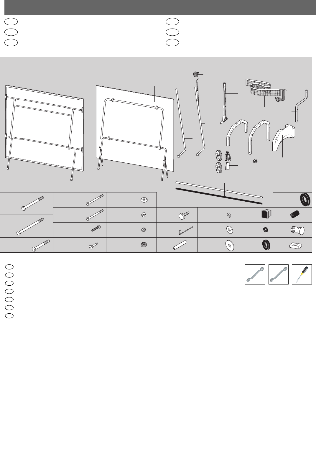
2x M8
8x M6
4x M6
22x ø12
18x ø16
10x ø25
8x
4x
4x
4x M8 2x ø20
2x
4x M6x55
4x M8x45
4x M6x60
4x M6x35
6x M6x36
4x M8x110
2x M8x120
4x
2x
2x
2x
1x
2x
2x
2x
1x
2x
1x
2x
4x
2x
(7042)
2x
(7043)
2x
4x
2x
2x1x 2x
6x
2x
4x ø26
SW13 SW10
2x 2x 1x
GB E
F
NL
I
PL
Checkliste (Packungsinhalt)
Checklist (contents of packaging)
Liste de vérification (contenu de l’emballage)
Checklijst (verpakkingsinhoud)
Lista de control (contenido del paquete)
Lista di controllo (contenuto del pacco)
Lista kontrolna (zawartość opakowania)
Sie benötigen zusätzlich folgendes Werkzeug (Gehört nicht zum Lieferumfang):
You also need the following tools (Not included):
Vous avez besoin de cet util en complément (con compris dans la livraison)
U heeft tevens volgend gereedschap nodig (Is niet in de levering ingesloten):
Usted necesita adicionalmente la siguiente herramienta (no pertenece al volumen de suministro):
Per eseguire il montaggio, Vi occorre il seguente attrezzo (non è incluso nel volume di fornitura):
Dodatkowo potrzebne są następujące narzędzia (nie objęte zakresem dostawy):
PL
I
E
NL
F
GB
D
12
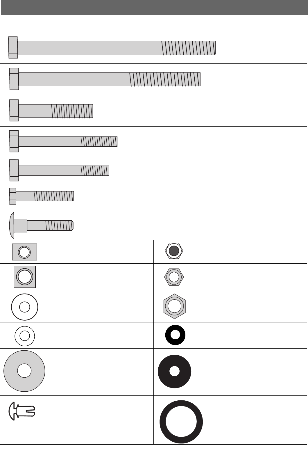
Actuel size of hardware
M8x120
M8x110
M8x45
M6x60
M6x55
M6x35
M6x37
M6
M8
ø16x6
ø12x6
ø25x8
6x9.5
M6
M6
M8
ø12x6
ø20x6
ø26x19
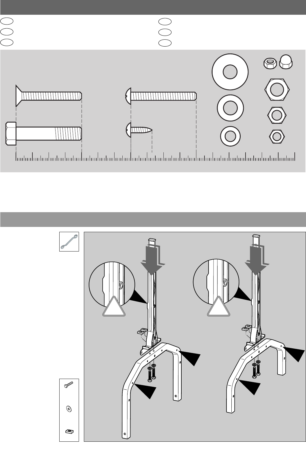
13
Messhilfe für Verschraubungsmaterial
Measuring help for screw connections
Gabarit pour système de serrage
Meethulp voor schroefmateriaal
Ayuda para la medición del material de atornilladura
Misura per materiale di avvitamento
Wzornik do połączeń śrubowych
GB
F
NL
E
I
PL
0 10 20 30 40 50 60 70 80 90 100 110 120 130 140 150 160 170
M5x40
M8x40
M8
˘22
˘16
˘12
M6
M5
˘3,9x13
Beispiele Examples Examples Bij voorbild Ejemplos
M5x40
1
4x
M6x35
4x
4x
ø12
!
!
14
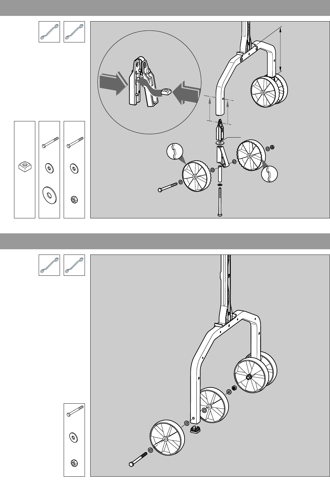
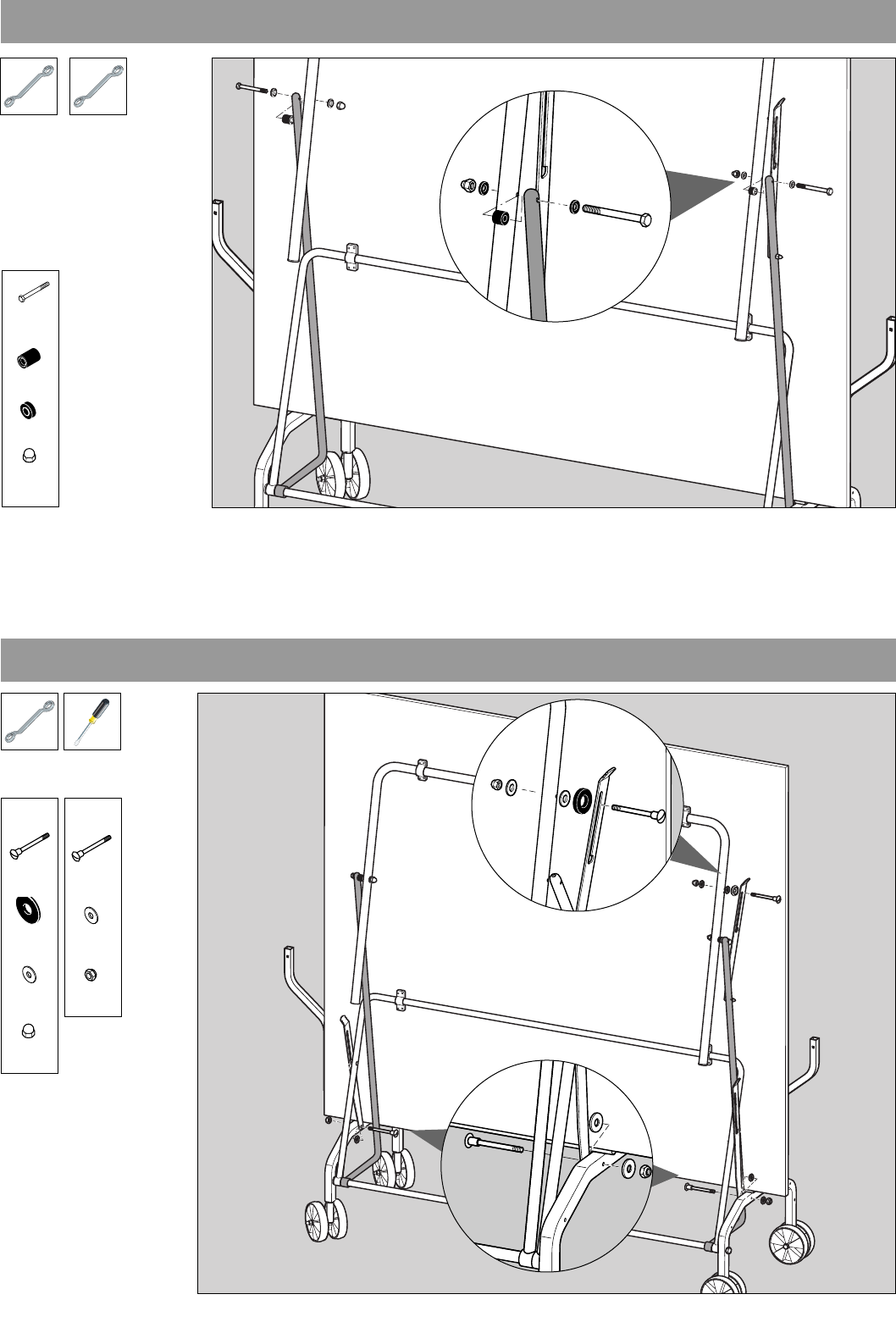
2
18,6cm
C
A
D
A
ø25
AB
B
2x
M8x120
2x
ø16
2x
ø25
2x
M8
C
2x
M8x110
8x
ø16
2x
M8
2x
M8x110
8x
ø16
2x
3
15
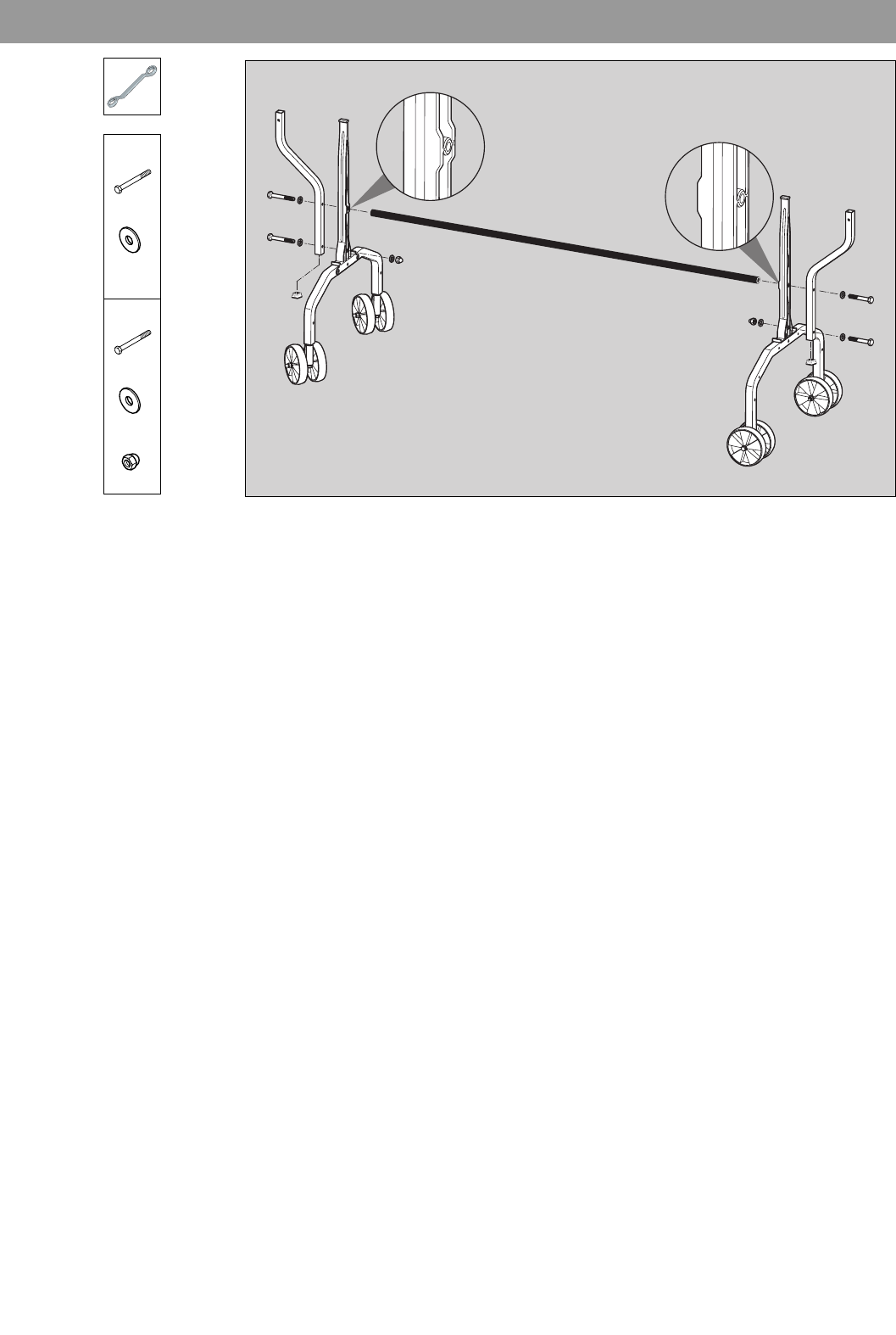
4
A
2x
M6x55
B
2x
ø16
B
2x
M6x55
4x
ø16
2x
A
B
A
16
5
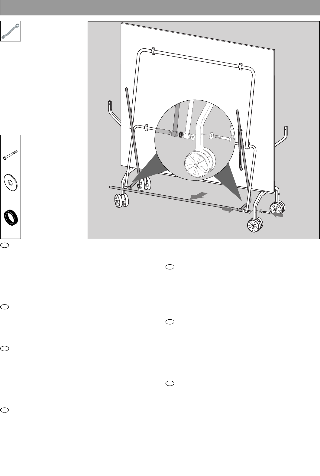
B: Die Streben des Tragrahmens müssen hierbei ein wenig
zur Seite gebogen werden; gehen Sie hierbei vorsichtig vor!
C: Setzen Sie nun eine Plattenhälfte auf. Sichern Sie die Plat-
tenhälfte für die folgenden Montageschritte unbedingt gegen
Abrutschen und/oder Umkippen! Lassen Sie von einer zwei-
ten Person auf jeder Seite die Schubstrebe und die Tragrah-
menstrebe auf das letzte Verbindungsrohr aufschieben.
D: Das Verbindungsrohr wird nun mit den Seitenteilen ver-
schraubt.
B: To do this, the braces for the frame must be bent slightly to
the side. Proceed with care when doing this.
C: Position one of the table halves and ensure that it cannot
slip or tilt over. Ask another person to attach the push bar and
the support-frame brace to the last connecting bar.
D: The connecting bar is now bolted to the side elements.
B: Pour cela les jambes de forces du cadre porteur doivent
être pliées un peu de côté; pratiquer là avec précaution.
C: Poser un plateau. Il est absolument nécessaire de sécuriser
les plateaux pour les opérations de montage qui suivront, afin
qu’ils ne puissent ni glisser ni se renverser. Demander à une
autre personne de glisser de chaque côté l’entretoise et la
jambe de force du cadre porteur sur le dernier tube de jonc-
tion.
D: Visser ensuite le tube de jonction aux pièces de côté.
B: De stangen van het draagframe moeten hierbij aan de
kant enigszins gebogen worden; ga bierbij voorzichtig te
werk!
C: Stel een bladhelft op. Blokkeer deze bladhelft voor het vol-
gende deel van de montage tegen wegglijden en/of kante-
len. Laat een volwassene aan elke zijde de schuifstang en het
NL
F
GB
D
draagframe over de laatste verbindinggsbuis schuiven.
D: De verbindingsbuis moet nu aan de zijdelen worden vast-
geschroefd.
B: Los puntales del marco soporte tienen que ser ligeramente
doblados; ¡ejecute este proceso con cuidado!
C: Ponga la mitad de la plancha. ¡Asegure la mitad de la
plancha para los próximos pasos de montaje contra desliza-
miento y/o vuelco! Deje que una segunda persona empuje a
cada lado el puntal de empuje y el puntal del marco en el úl-
timo tubo de unión.
D: El tubo de unión es atornillado con las partes laterales.
B: A questo proposito è necessario piegare leggermente verso
il lato i montanti della staffa di supporto; procedere con cautela!
C: Dispore un semipiano. Assicurarsi che il semipiano sia fis-
sato bene, in modo da non scivolare o ribaltarsi durante le
fasi successive di montaggio! Da una seconda persona far
posizionare i sostegni scorrevoli su ciascun lato e il sostegno
del telaio portante sull’ultimo tubolare di collegamento.
D: Il tubolare di collegamento adesso avvitato con i compo-
nenti laterali.
B: Poprzeczki pałąka podporowego muszą zostać przy tym
nieznacznie rozgięte na zewnątrz. Zachować przy tym
ostrożność!
C: Po jednej stronie ułożyć połówkę płyty. Dla następnych
operacji montażowych należy koniecznie zabezpieczyć
połówkę płyty przed ześlizgnięciem się i/lub przewróceniem
się! Poprosić drugą osobę o nasunięcie po obu stronach po-
pychaczy ukośnych i podpór ukośnych ramy na ostatnią rurę
łączącą.
D: ura łącząca skręcona zostaje teraz z częściami bocznymi.
PL
I
E
2x
M8x45
4x
ø25
D
A
A
B
C
2x
ø26
17
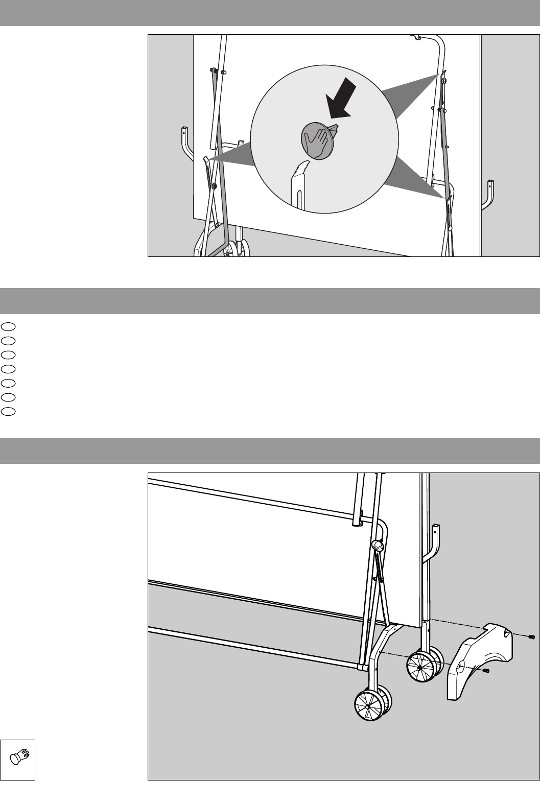
6
2x
M6x60
4x
2x
2x
M6
7
4x
ø12
2x
M6
1x
M6
1x
M6x36
2x
M6x36
2x
ø12
1x
ø20
A
A
B
B
B
A
B
18
10
9
8
Führen Sie die Schritte 5 bis 8 für die zweite Plattenhälfte durch. Denken Sie auch hier wieder an die Sicherung der Platte!
Carry out steps 5–8 for the second half of the table. Again, ensure that the table cannot slip or tilt over!
Effectuer les opérations 5 à 8 pour la deuxième moitié de table. Là non plus, ne pas oublier la sécurisation du plateau.
Voer de montagestappen 5 tot 8 voor de tweede bladhelft uit. Denk ook hierbij weer aan de vergrendeling van het blad!
Ejecute los pasos 5 a 8 para la segunda mitad de la plancha.
Ripetere le operazioni da 5 a 8 anche per il sesondo semipiano
Powtórzyć kroki 5 do 8 dla drugiej połówki płyty.
D
GB
F
NL
E
I
PL
CLICK!
CLICK!
19
Herunterklappen der Plattenhälften
Lowering the table halve
Rabattre les moitiés de la table
Neerslaan van de plaathelften
Despliegue de los dos segmentos de la placa
Ribaltare le metà del tavolo
Opuszczanie płyt stołu
GB E
F
NL
I
PL
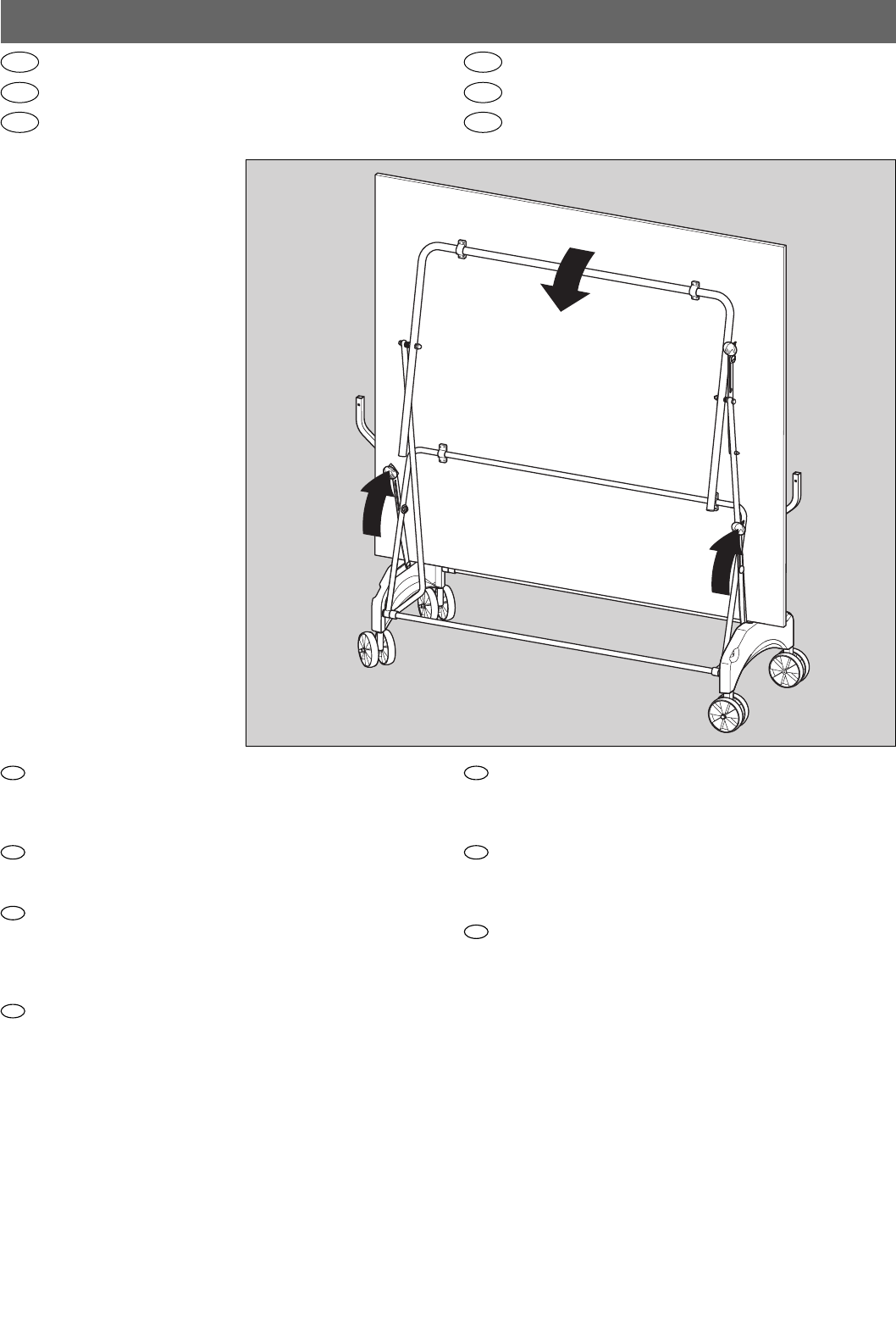
Drücken Sie die rechte Kippsicherung. Anschließend die Plat-
te mit einer Hand festhalten, linke Kippsicherung drücken und
Platte langsam herunterklappen (Platte unter keinen Umstän-
den einfach fallen lassen!).
Press the right-hand tip lock. Hold the table firmly with one
hand, press the left-hand lock and lower the table-half slowly
into position. Never allow it to drop down!
Appuyer sur la sécurité de basculement de droite. Tenir en-
suite le plateau d’une main, appuyer sur la sécurité de bas-
culement de gauche et laisser descendre lentement le plateau
(en aucun cas on ne pourra le laisser tout simplement tom-
ber).
Druk de rechter kiepvergrendeling in. Houd het blad dan met
een hand vast, druk op de linker kiepvergrendeling en klap
het blad langzaam naar beneden (laat het blad in geen ge-
val zomaar vallen!).
NL
F
GB
D
Presione el seguro derecho. Sujete a continuación la plancha
con una mano y presione el seguro izquierdo contra vuelco.
Baje lentamente la plancha (¡no deje caer la plancha por
ningún motivo!).
Premiere il pulsante antiribaltamento destro. Sostenendo il pi-
ano con una mano, premere il pulsante antiribaltamento si-
nistro e abbassare lentamente il piano stesso (per nessun mo-
tivo lasciare il piano in caduta libera!)
Nacisnąć prawe zabezpieczenie przed przewróceniem się.
Następnie przytrzymać płytę jedną ręką, nacisnąć zabez-
pieczenie przed przewróceniem się po lewej stronie i powo-
li opuścić płytę (pod żadnym pozorem nie pozwolić płycie
opaść pod własnym ciężarem!).
PL
I
E
C
A
B
20
Zusammenklappen der Plattenhälften
Collapsing the table halves
Replier les moitiés de la table
Tesamenslaan van de plaathelften
Plegar los segmentos de las placas
Chiudere le metà del tavolo
Składanie płyt stołu
GB E
F
NL
I
PL
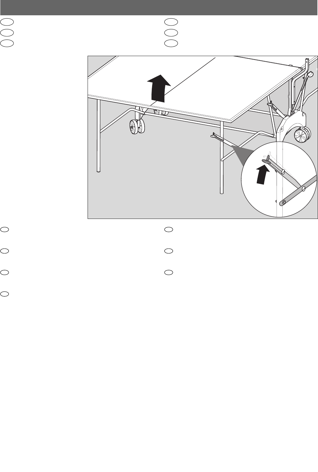
Drücken Sie den Hebel der Standsicherung nach oben und
heben Sie die Plattenhälfte an. Behalten Sie in der Anfangs-
phase des Hochklappens den Druck bei.
Press the locking lever up and lift the table half upwards. Con-
tinue to press the lever during the first part of the upward mo-
tion.
Pousser le levier de la sécurité vers le haut et soulever le demi-
plateau. Maintenir la pression dans la phase initiale du re-
dressement.
Druk de linker kiepvergrendeling naar boven en til de blad-
helften op. In het begin dient u hierbij druk uit te oefenen.
F
GB
D
NL
Presione la palanca de seguro de la estabilidad hacia arriba
y levante la mitad de la mesa. Mantenga la presión en la
fase inicial del levantamiento.
Premere verso l’alto la leva del dispositivo stabilizzatore e
sollevare il semipiano. Mantenere la pressione nella fase ini-
ziale del sollevamento del semipiano.
Obrócić dźwignie podpór w górę i podnieść połówkę płyty.
W początkowej fazie podnoszenia należy nadal naciskać
zabezpieczenia.
E
I
PL
A
B
21
2
1
2x
M5x32 M5
B
A
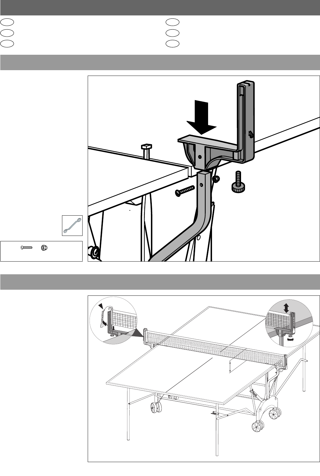
C
Montage des Netzhalters
Instructions for Assembling the net set
Instructions de montage pour l’ensemble poteaux-filet
Montage van de netpost
Montaje del portared
Montaggio dell’attacco della rete
Montaż uchwytu siatki
GB E
F
NL
I
PL
15 cm
22
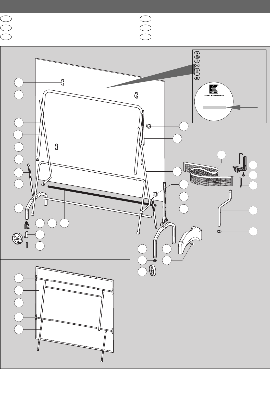
Ersatzteilzeichnung
Spare parts drawing and list
Dessin et liste des pièces de rechange
Reserveonderdeeltekening en -lijst
Designación y lista de las piezas de recambio
Disegno ed elenco dei pezzi di ricambio
Rysunek i lista części zamiennych
GB E
F
NL
I
PL
8
1
9
3
4
15
14
21
11
12
21
17
5
2
20
27 16
24
18
13
10
1
2
4
10
28
19
31
32
35
30
33
34
36
5
6
7042
7043
Typenschild – Seriennummer
Type label – Serial number
Plaque signalétique – Numèro de serie
Typeplaatje – Seriennummer
Placa identificativa – Número de serie
Targhetta tecnica – Numero di serie
Tabliczka identyfikacyjna – Numer serii
HEINZ KETTLER GmbH & Co. KG
D-59469 Ense-Parsit
Art.-Nr. 07044-000
1-334 O - 1801 00001
geprüft nach prEN 14468-1, -2
Klasse C, Typ 4
Made in Germany
23
1 TT-Platte (BITTE UNBEDINGT ARTIKEL-NUMMER DES TT-TISCHES ANGEBEN!) 2 94130117 94130000 94130125 94130003
2 Fussbügel/-gestell mit Bodenschonern 2 94111232 94111232 94111247 94111247
3 Bodenschoner 4 70130540 70130540 70130540 70130540
4 Stützbügel (mit Rohrverbindern, Sicherungen, Bundschrauben M6x30mm) 2 94111237 94111237 94111250 94111250
5 Sicherungshebel 1 4 94111234 94111234 94111234 94111234
6 Sicherungshebel 2 2 94111233 94111233 94111233 94111233
8 Rohrschelle für ø25mm 4 94110341 94110341 – –
9 Rohrschelle für ø18mm 4 94110192 94110192 – –
10 Lagerböckchen 8 – – 10128028 10128028
11 Schubstange 2 94111239 94111239 94111239 94111239
12 Schubstange mit Sicherungshebel 2 94111240 94111240 94111240 94111240
13 Verbindungsstange 2 94110912 94110912 94110912 94110912
14 Grundbügel (714mm) 1 94111242 94111242 94111242 94111242
15 Radhalter 2 70130811 70130811 70130811 70130811
16 Grundbügel (895mm) mit Stopfen für VKT 25mm 1 94111246 94111246 94111246 94111246
17 Abweisstange 2 70130607 70130607 70130607 70130607
18 Seitenverkleidung 2 70130608 70130608 70130608 70130608
19 Räder-Satz (4 Stück) mit Radverbinder 2 94180177 94180177 94180177 94180177
20 Radverbinder 2 70130812 70130812 70130812 70130812
21 Handdruckplatte 6 70130532 70130532 70130532 70130532
22 Bundschraube M6x37mm (o.Abb.) 6 10201209 10201209 10201209 10201209
24 Stopfen für VKT 25mm 2 10100046 10100046 10100046 10100046
25 6kant-Schraube M8x120mm (o.Abb.) 2 10206084 10206084 10206084 10206084
26 6kant-Schraube M8x110mm (o.Abb.) 4 10206081 10206081 10206081 10206081
27 Distanzrohr ø12x1,8x64mm 2 97201453 97201453 97201453 97201453
28 Spreizniet ø6x9,5 4 10418503 10418503 10418503 10418503
29 Schraubenbeutel (o. Abb.) 1 94180338 94180338 94180338 94180338
30 Netzhalter Automatik 2 94110103 94110103 94110103 94110103
31 Netz (kpl.) 1 94180065 94180065 94180065 94180065
32 Spannlasche 2 10128002 10128002 10128002 10128002
33 Netzhalter 2 94111243 94111243 94111243 94111243
34 Stopfen für VKT 20mm 2 10100095 10100095 10100095 10100095
35 Rändelschraube 2 10106000 10106000 10106000 10106000
36 Verbindungsstange 1 94111241 94111241 94111241 94111241
37 Schraubenbeutel für Netzmontage (o. Abb.) mit Stopfen für VKT 20mm 1 94180143 94180143 94180143 94180143
Teil Bezeichnung Stück Ersatzteil-Nr. Ersatzteil-Nr. Ersatzteil-Nr. Ersatzteil-Nr.
Nr. 07042-700 07042-900 07043-700 07043-900
blau/schwarz grün/schwarz blau/schwarz grün/schwarz
nicht wetterfest nicht wetterfest wetterfest wetterfest
Ersatzteilliste
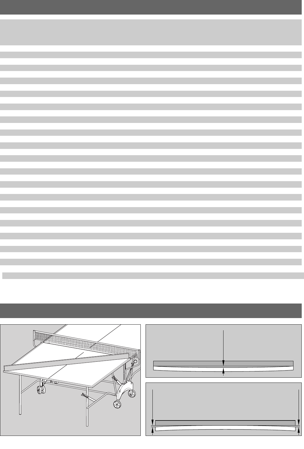
max 1 cm = ok.
max 1 cm = ok.
max 1 cm = ok.

docu 1064m/02.10
HEINZ KETTLER GmbH & Co. KG · Postfach 1020 · D-59463 Ense-Parsit
www.kettler.net
