King of Fans 52SNMS2 52 inch Noah User Manual HDC 52in Noah was Sonoma IM English 01052016
King of Fans, Inc. 52 inch Noah HDC 52in Noah was Sonoma IM English 01052016
UserManual.wiki
>
King of Fans
>
52SNMS2 User Manual
User manual
Navigation menu
Upload a User Manual
Namespaces
Wiki Guide
HTML
PDF
Info
Views
User Manual
Discussion / Help
Navigation
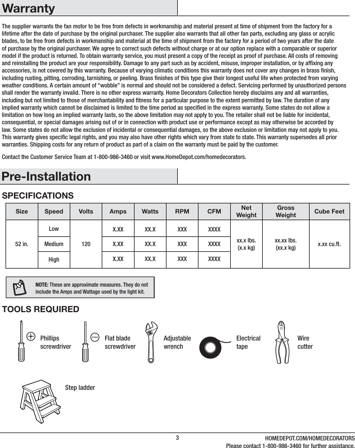
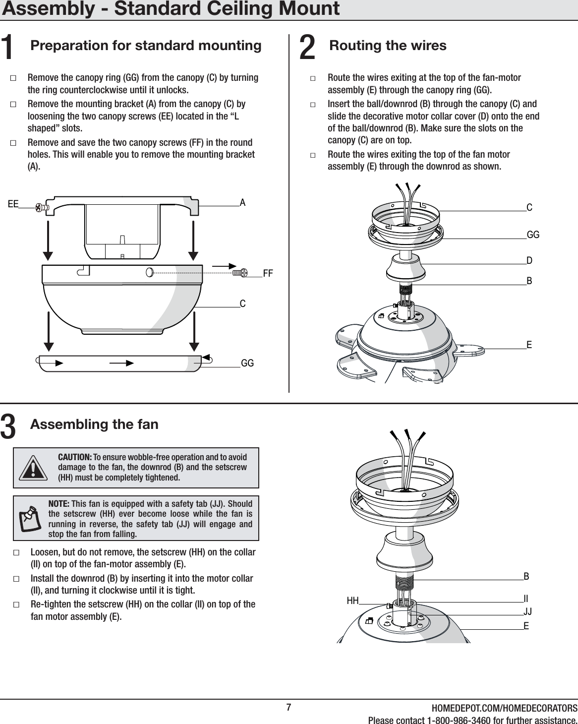

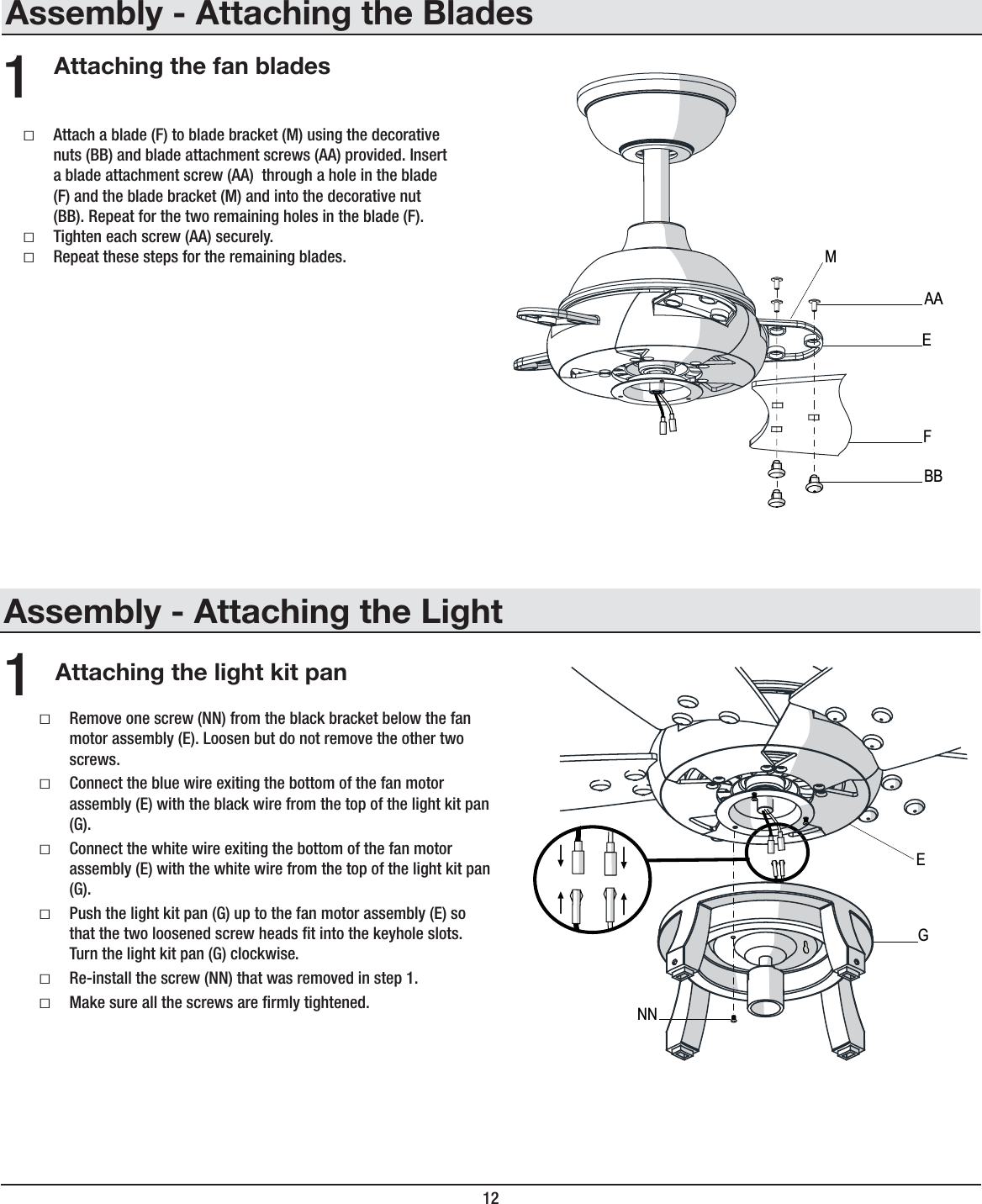

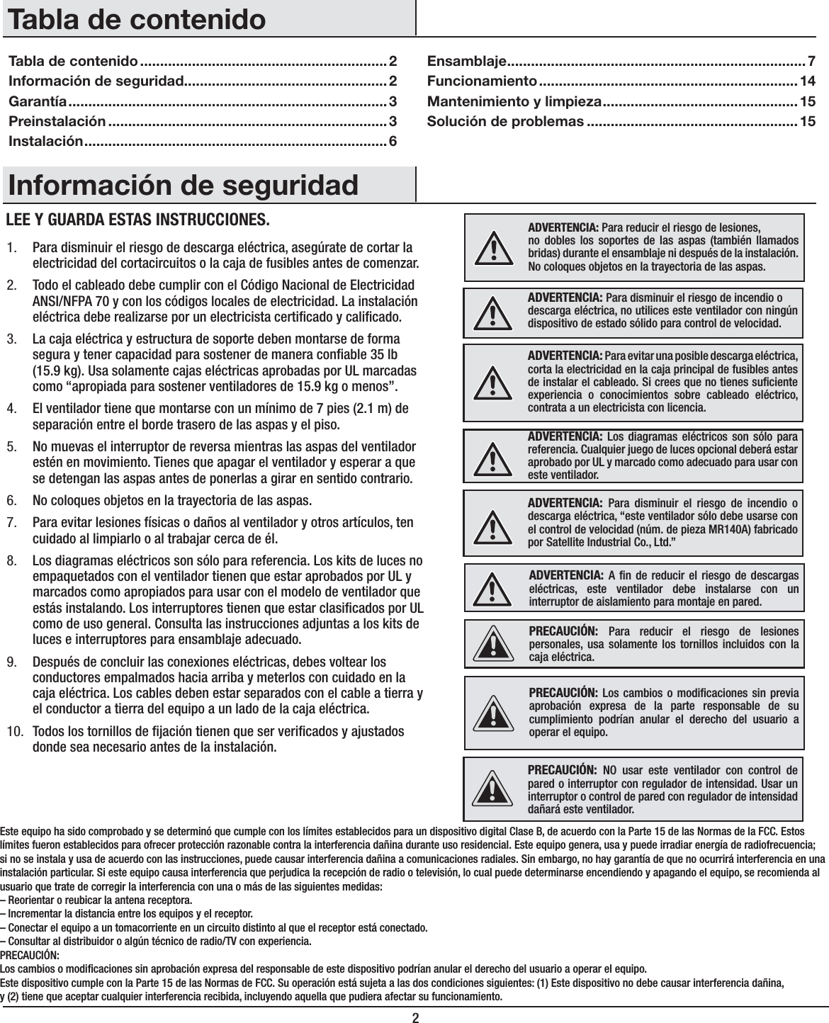
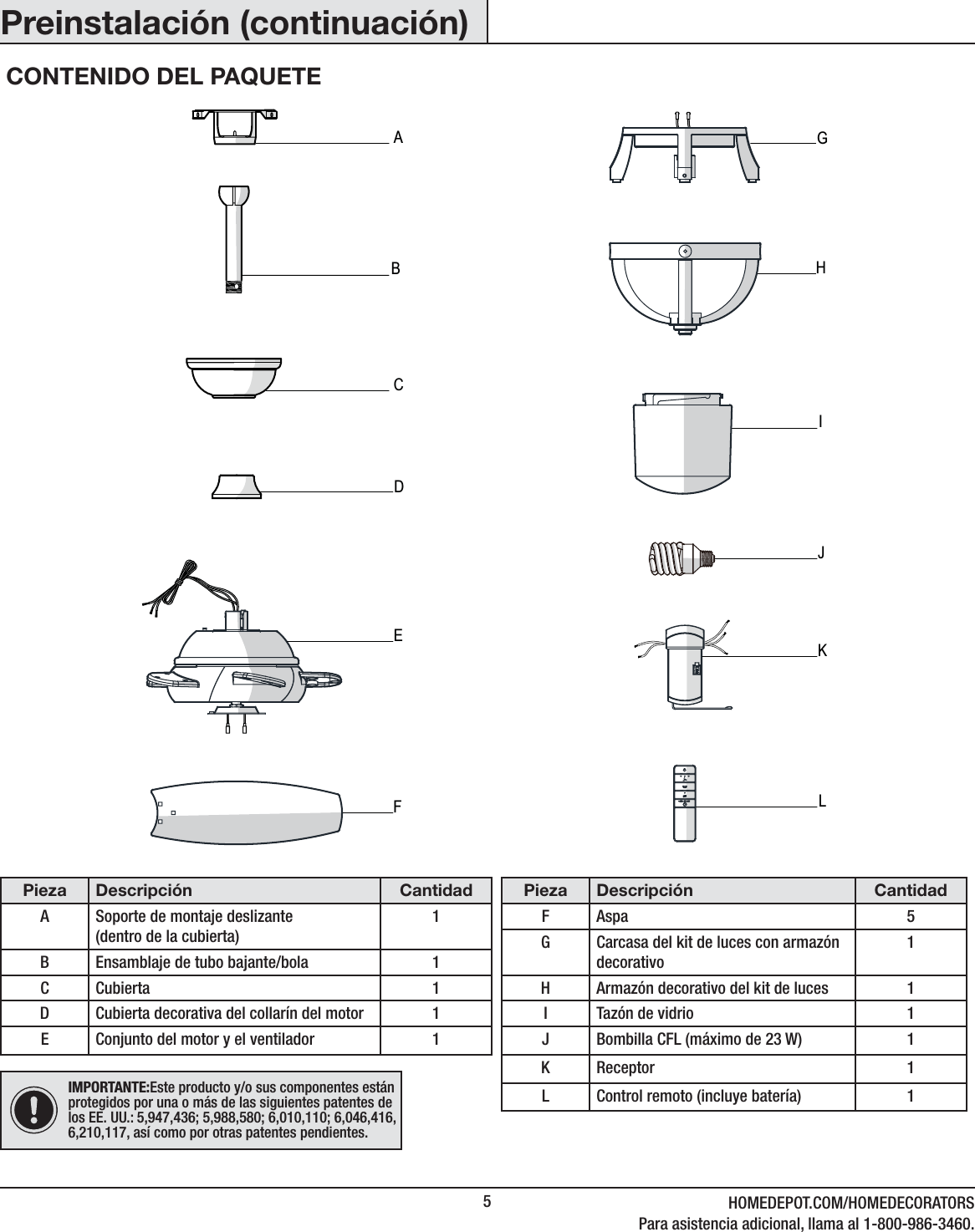
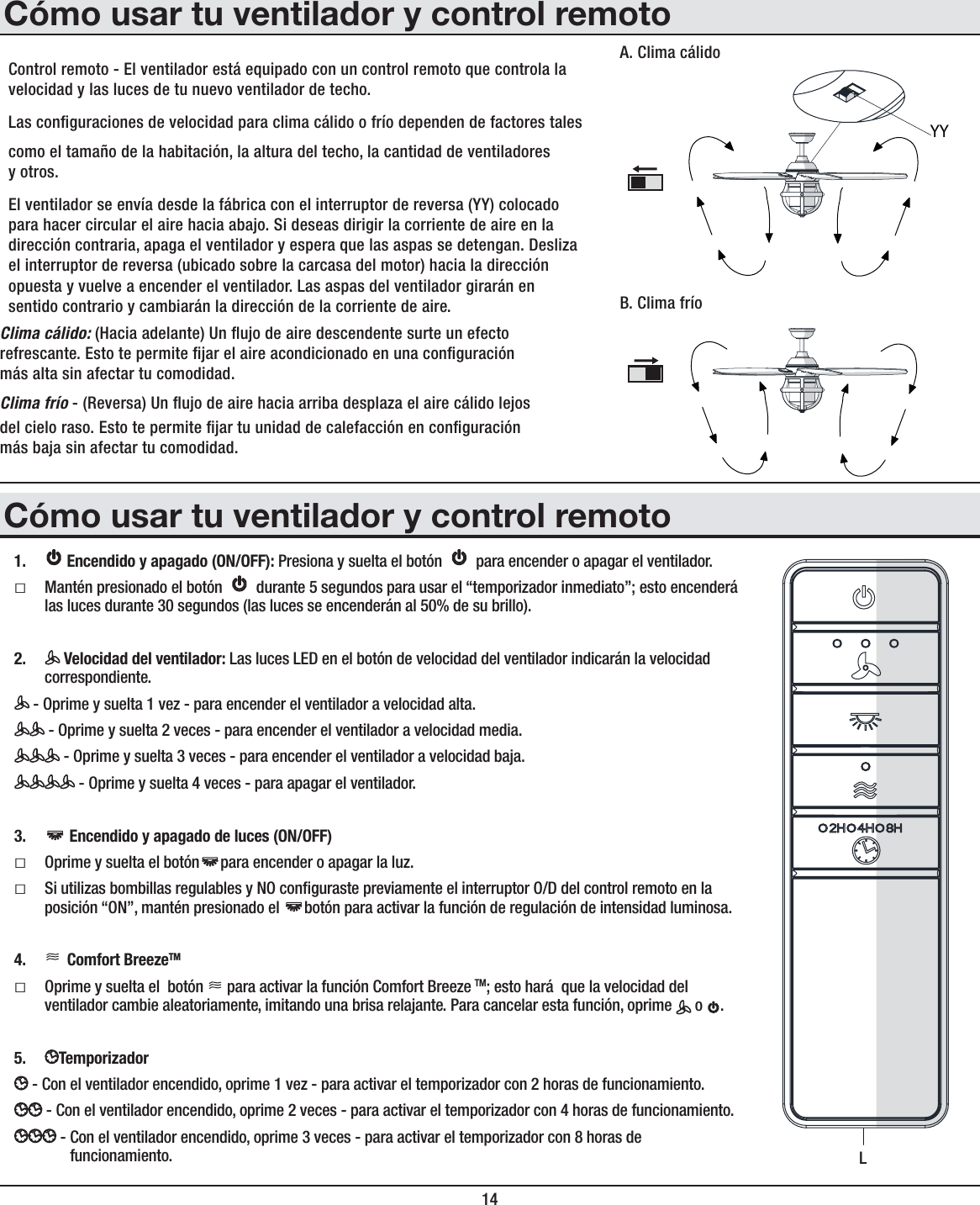
![6InstalaciónOPCIONES DE MONTAJE(+=,9;,5*0(! Para reducir el riesgo de incendio, descarga eléctrica o lesiones personales, instala en una caja eléctrica clasicada como “apropiada para sostener ventiladores de 35 lb (15.9 kg) o menos” y usa los tornillos que vienen con ella. Las cajas eléctricas utilizadas comúnmente para el soporte de lámparas pueden no servir como soporte para ventilador y tal vez sea necesario reemplazarlas. En caso de duda, consulta a un electricista calicado.Si tu ventilador de techo no tiene una caja de montaje aprobada por UL, instala una siguiendo las instrucciones a continuación:ƑDesconecta la energía retirando los fusibles o apagando loscortacircuitos.ƑAsegura la caja eléctrica directamente a la estructura de la edicación. Usa los sujetadores y materiales apropiados. La caja eléctrica y su soporte tienen que sostener completamente el peso en movimiento del ventilador [al menos 35 libras (15.9kg)]. No uses una caja eléctrica de plástico.Las ilustraciones a continuación muestran tres formas distintas de montar la caja eléctrica.Si la cubierta (C) toca el conjunto del tubo bajante/bola (B), retira la tapa inferior decorativa de la cubierta y gira 180º esta última (C) antes de jarla a la placa de montaje.Para colgar el ventilador donde hay una lámpara pero ninguna viga de techo, tal vez necesites una barra colgante, como se muestra más arriba(disponible en cualquier tienda de The Home Depot).56;(! Tal vez necesites un tubo bajante más largo para mantener la altura mínima adecuada de las aspas, al instalar el ventilador en un techo inclinado. El ángulo máximo permitido es 30º desde la horizontal.CajaEléctricaCaja eléctricaCajaeléctricaempotradaProvee soporte fuertePlaca paramontajeen el techoCaja eléctricaBarra para colgar](https://usermanual.wiki/King-of-Fans/52SNMS2/User-Guide-3477495-Page-22.png)
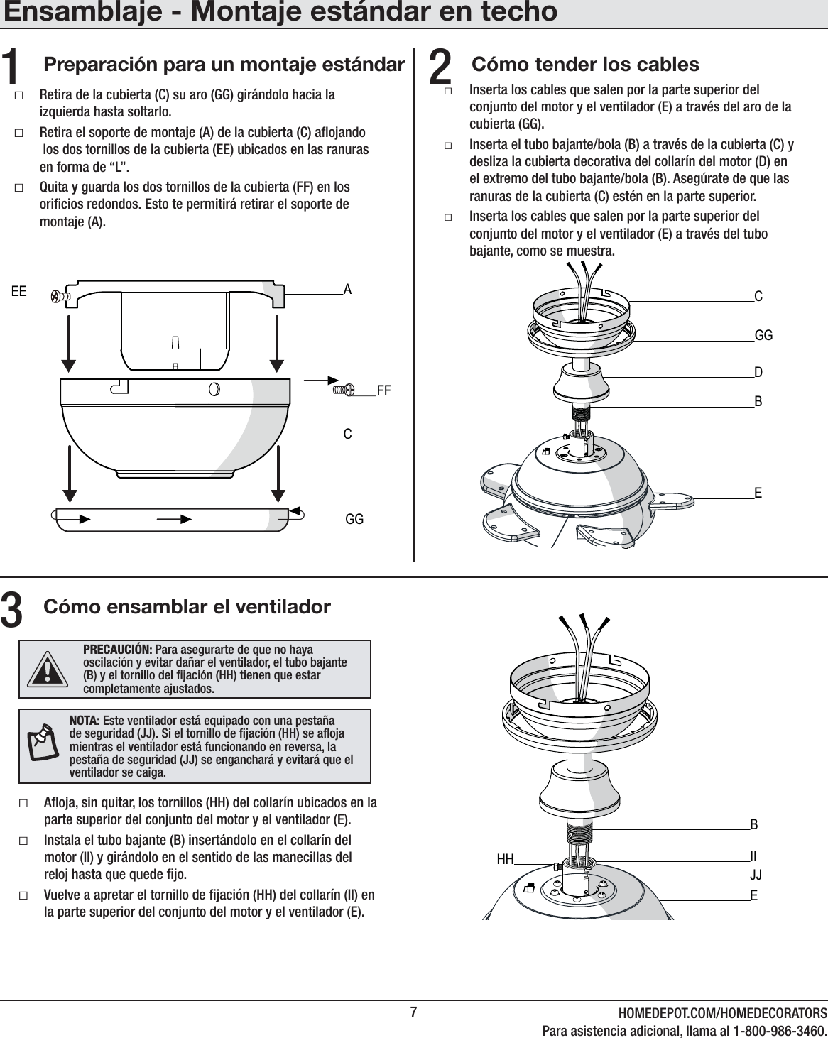
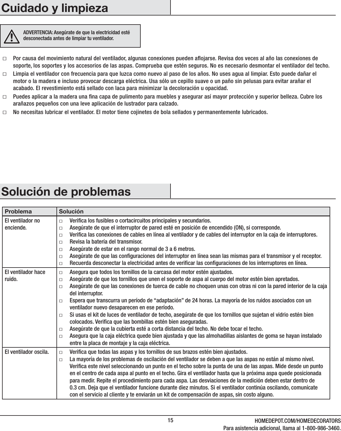
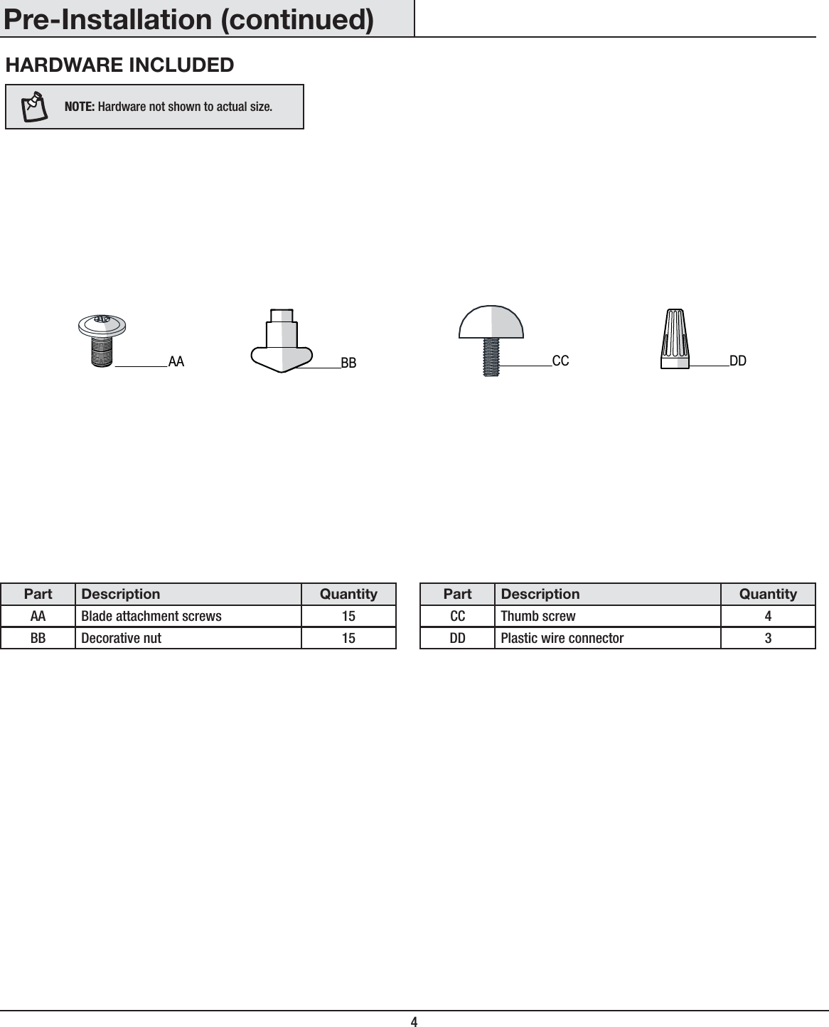
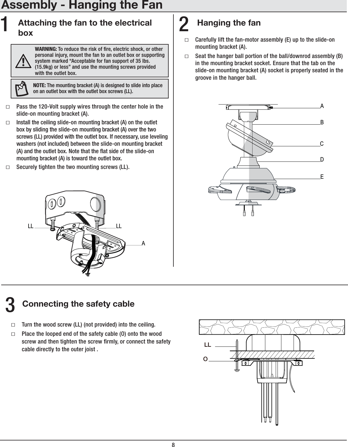
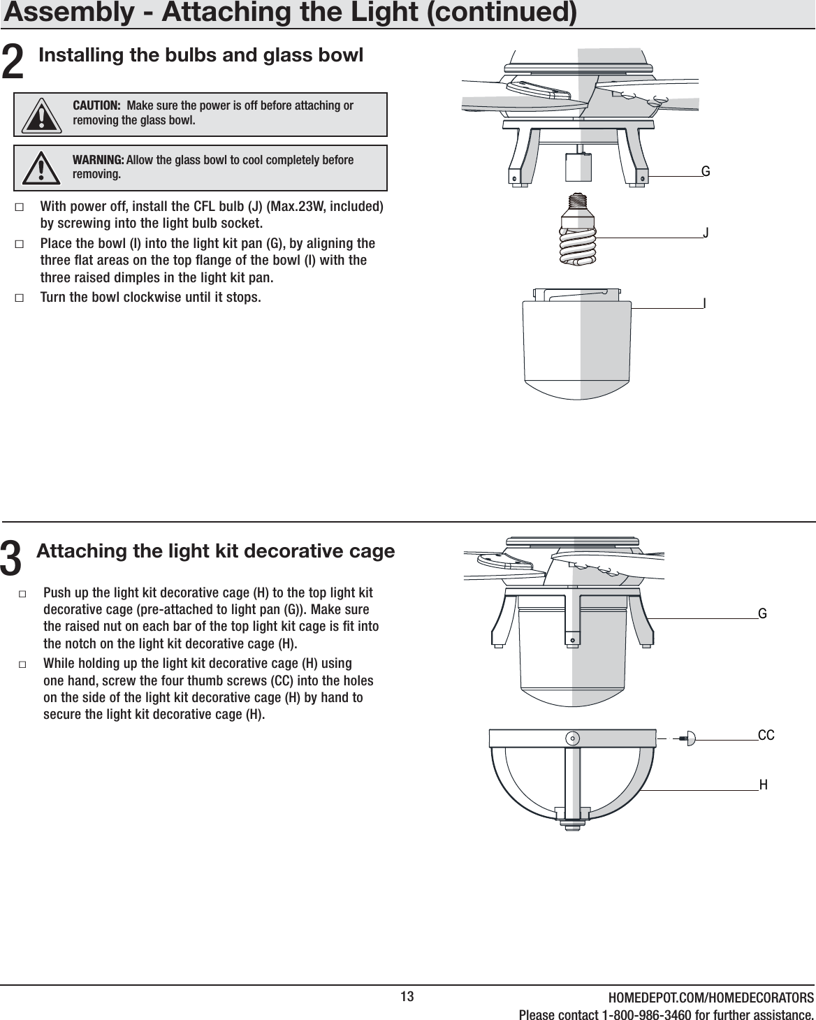
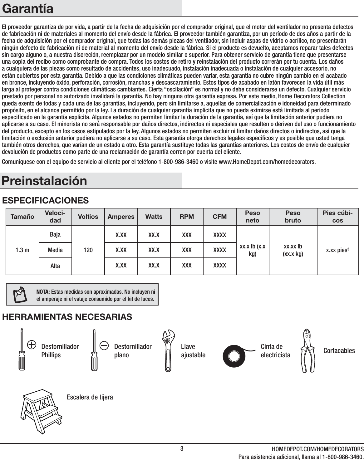
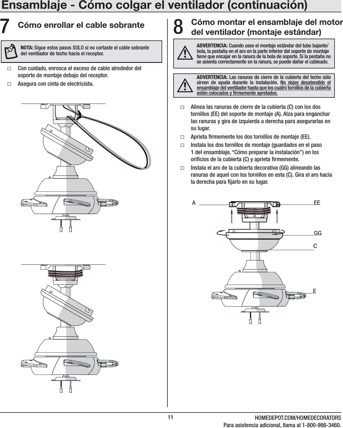
![10Ensamblaje - Cómo colgar el ventilador (continuación)5Cómo cablear el receptor al cableado del hogar04769;(5;,! Usa las tuercas de conexión de cables (DD) que vienen con tu ventilador. Sujeta los conectores con cinta de electricista y asegura que no haya conexiones ni cables sueltos.(+=,9;,5*0(! Cada tuerca para cable suministrada con este ventilador está diseñada para aceptar hasta un cable doméstico de calibre 12 y dos cables del ventilador. Si tienes un cableado doméstico que exceda del calibre 12 o más de un cable doméstico para conectar al cableado del ventilador, consulta a un electricista para el tamaño adecuado de las tuercas para cables a usar.ƑSepara los cables de manera que el verde y el blanco queden de un lado de la caja eléctrica y el negro quede del otro lado. ƑConecta los cables verdes del ventilador al cable con conexión a tierra de la casa (este puede ser verde o pelado) con una tuerca de conexión de cables (DD).ƑConecta el cable rojo del receptor (K) al cable negro (positivo) del hogar, usando una tuerca de conexión de cables (DD).ƑConecta el cable blanco del receptor (K) al cable blanco del hogar (neutro), usando una tuerca de conexión de cables (DD).ƑAsegura cada tuerca de conexión de cables con cinta de electricista.RojoNegroVerde (o pelado)VerdeCaja eléctrica en el techo (MM)ReceptorAntenaBlancoReceptor (K)DD (x3)1234ON DIP(+=,9;,5*0(! Para evitar una posible descarga eléctrica, apaga la electricidad en la caja principal de fusibles antes de instalar el cableado. Si crees que no tienes suciente conocimiento o experiencia sobre cableado eléctrico, contacta a un electricista certicado.Cómo cablear el ventilador al receptorƑEl ventilador viene con cables terminales de 1.37 m para usar con un ensamblaje extendido de tubo bajante/bola. Si usas el ensamblaje de tubo bajante/bola (B) de 15.2 cm incluido, puedes recortar los cables terminales al largo deseado (no menos de 34.3 cm). Esto dejará más espacio en la cubierta (C). Si no quieres cortar los cables, deberás enrollarlos cuidadosamente. ƑConecta el cable blanco del motor del ventilador al cable blanco del receptor usando una tuerca de conexión de cables (DD).ƑConecta el cable negro del motor del ventilador al cable negro del receptor usando una tuerca de conexión de cables (DD).ƑConecta el cable azul del motor del ventilador al cable azul del receptor usando una tuerca de conexión de cables (DD).ƑAsegura cada tuerca de conexión de cables con cinta de electricista. ƑGira la tuerca de conexión de cables (DD) hacia arriba y coloca el cableado dentro de la caja eléctrica (MM).604769;(5;,! Usa las tuercas de conexión de cables (DD) que vienen con tu ventilador. Sujeta los conectores con cinta de electricista y asegura que no haya conexiones ni cables sueltos.56;(!El ventilador viene con cables terminales de 1.37 m para usar con un ensamblaje extendido de tubo bajante/bola. Si usas el ensamblaje de tubo bajante/bola (B) de 15.2 cm (6 plg) incluido, puedes recortar los cables terminales al largo deseado [no menos de 34.3 cm (13.5 plg)].04769;(5;,!Si luego de este paso decides vericar que las conexiones se establecieron exitosamente, es fundamental instalar el kit de luces usando el conector rápido antes de proceder a la vericación. El ventilador funcionará sólo si el kit de luces está conectado al ventilador.Caja eléctrica en el techo (MM)Receptor (K)AzulReceptorAntenaNegro BlancoVerdeDD (x3)1234ON (ENCENDIDO)DIP](https://usermanual.wiki/King-of-Fans/52SNMS2/User-Guide-3477495-Page-26.png)
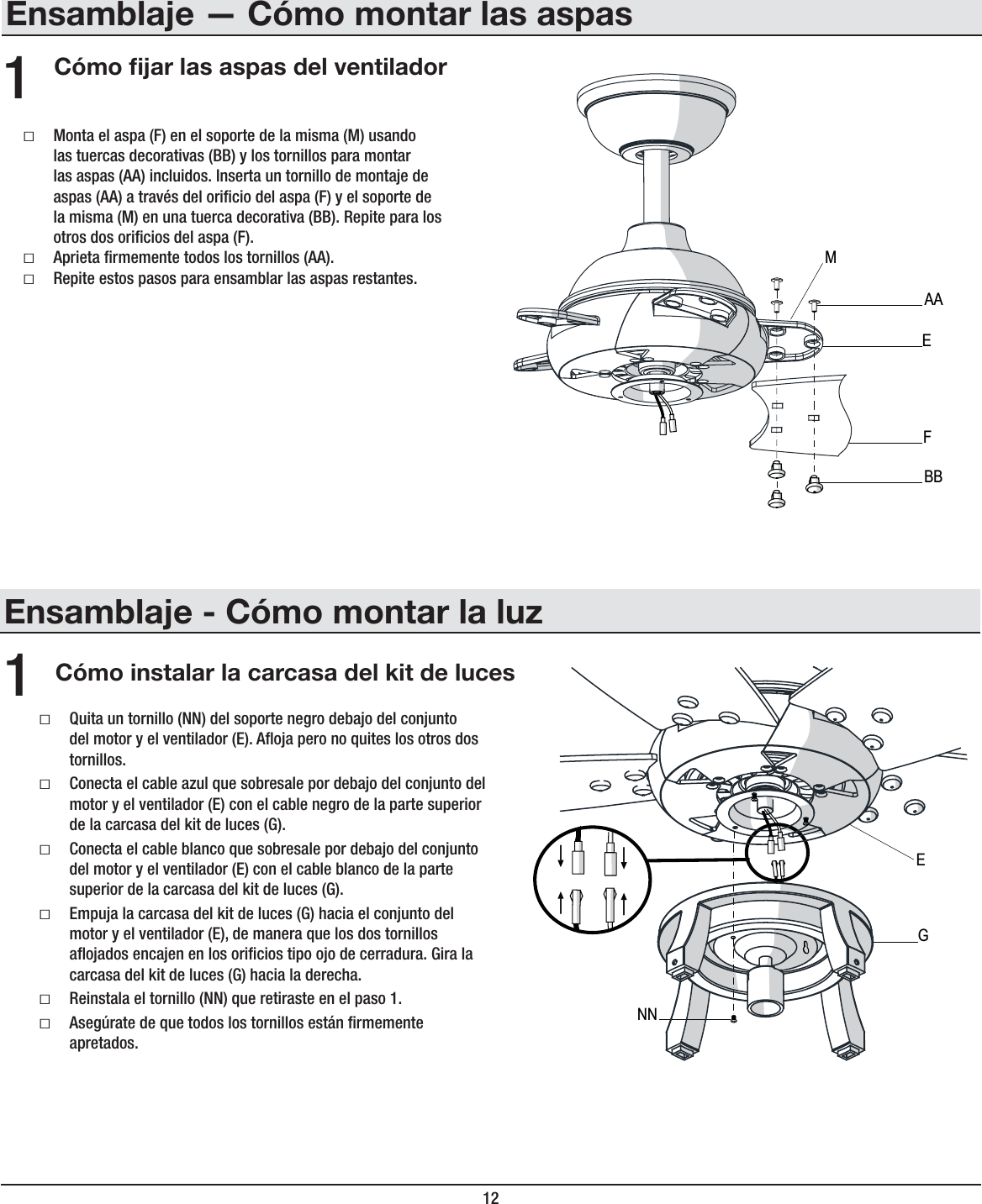
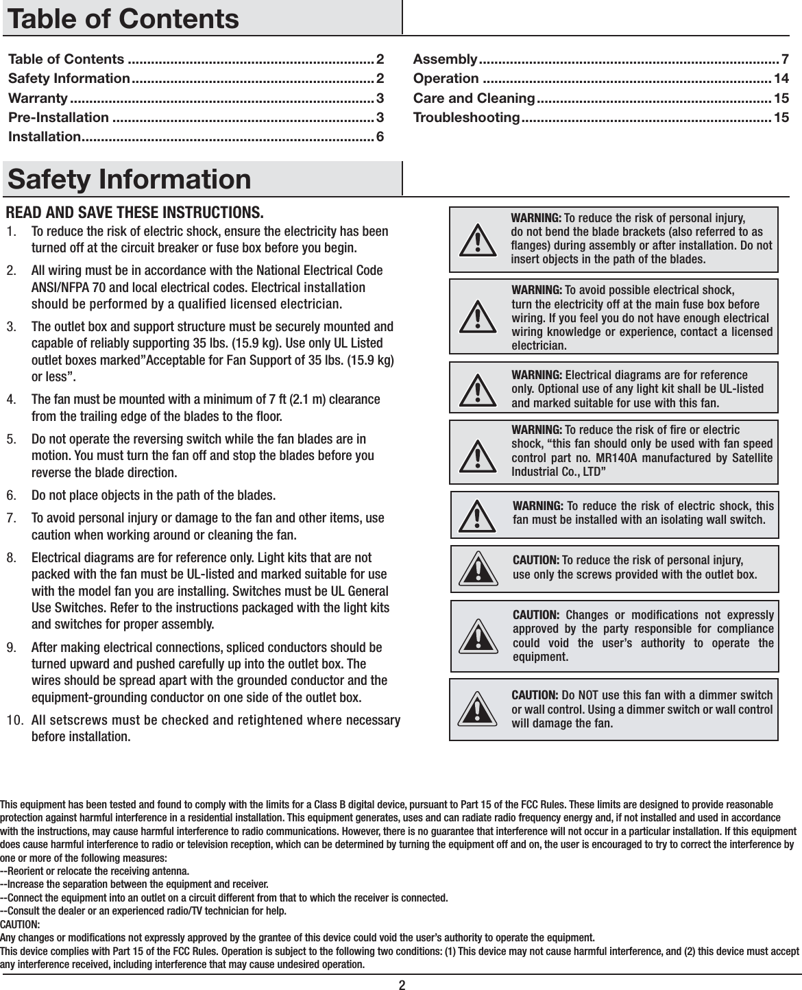
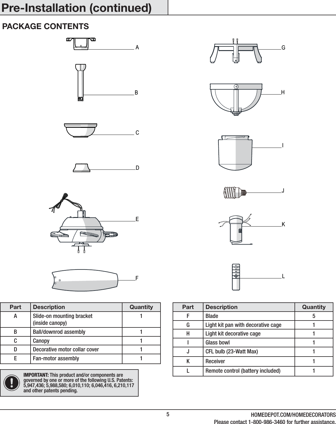
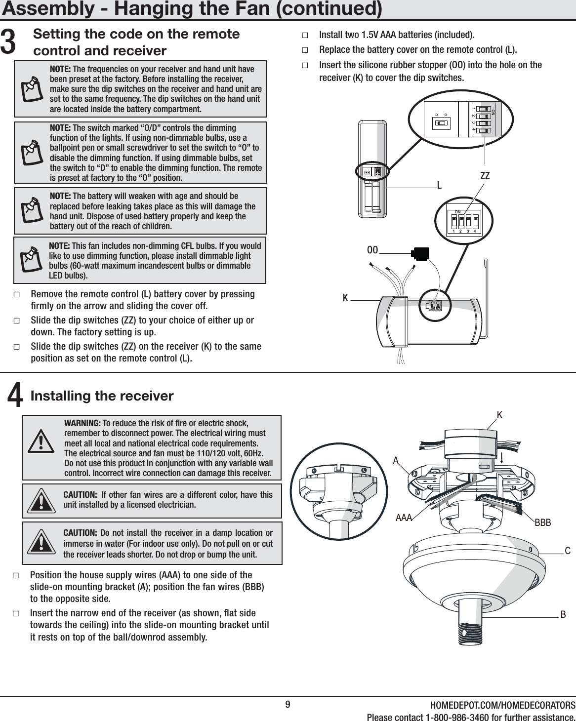
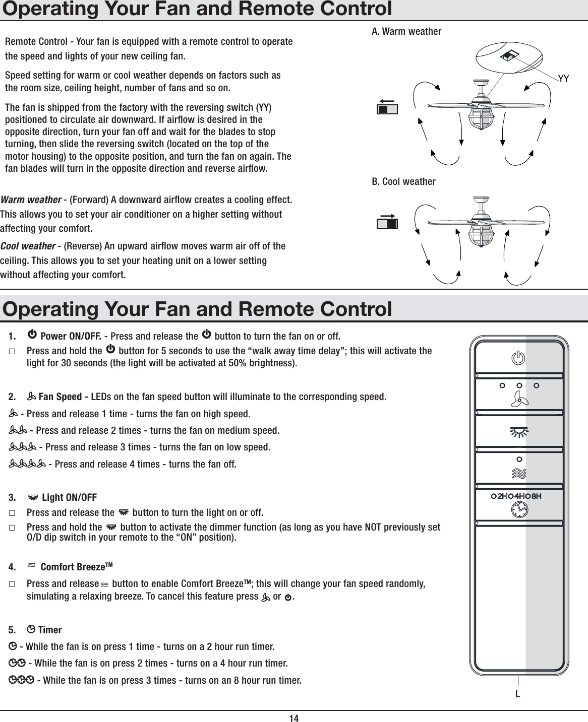
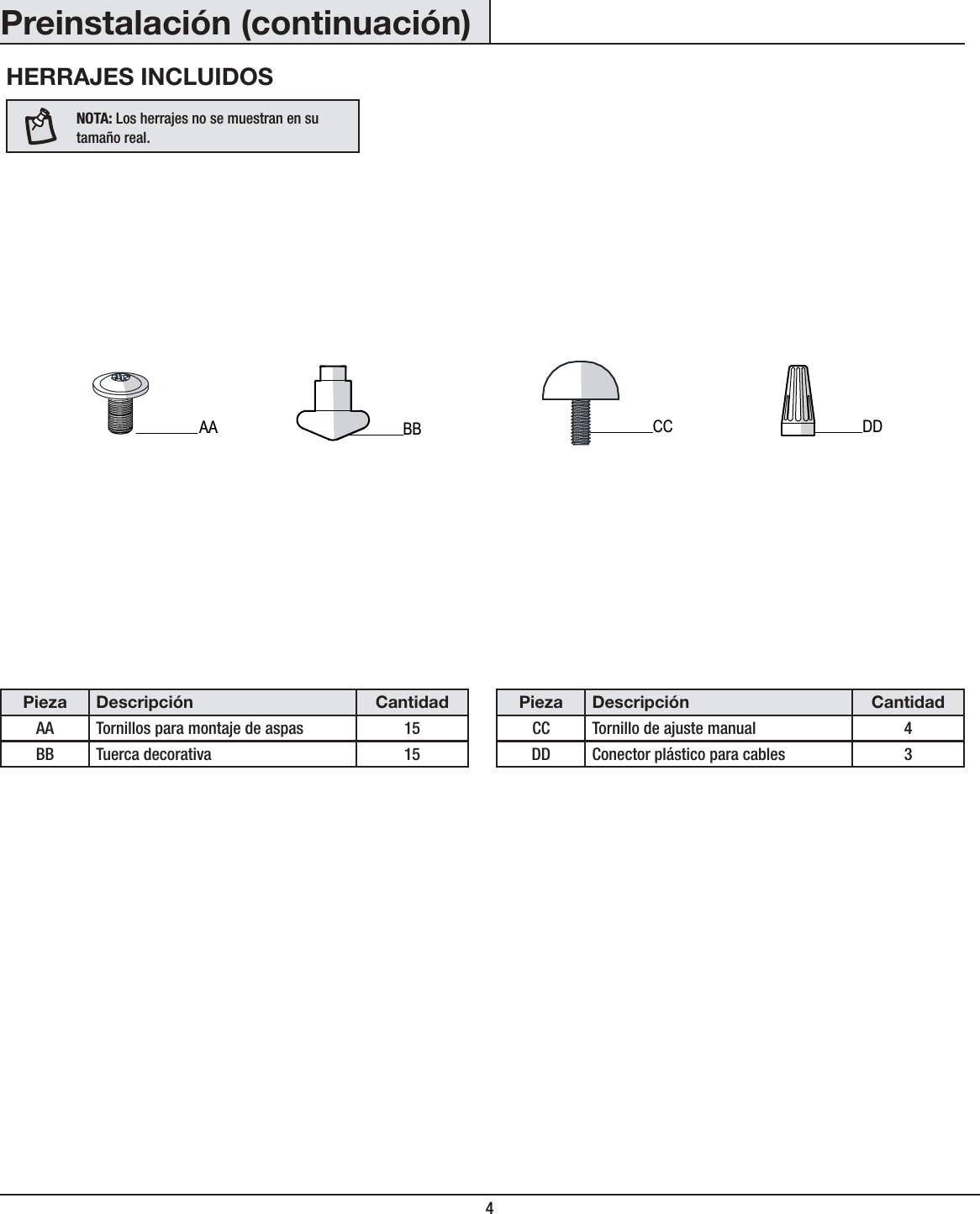
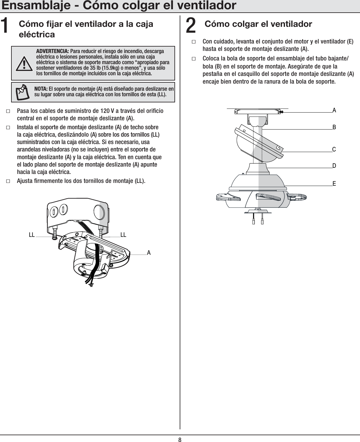
![13 HOMEDEPOT.COM/HOMEDECORATORSPara asistencia adicional, llama al 1-800-986-3460.Ensamblaje - Cómo montar la luz (continuación)Cómo instalar las bombillas y el tazón de vidrio2ƑCon el ventilador apagado, instala la bombilla CFL (J) (máximo 23 W, incluida) enroscándola en los portabombillas.ƑColoca el tazón (I) en la carcasa del kit de luces (G), alineando las tres áreas planas en el reborde superior del tazón (I) con las tres muescas salientes de la carcasa (G).ƑGira el tazón hacia la derecha hasta que se detenga.79,*(<*0Ô5! Asegúrate de que la corriente está cortada antes de montar o retirar el tazón de vidrio.(+=,9;,5*0(! Espera que el tazón de vidrio se enfríe completamente antes de retirarlo.JIGCómo instalar el armazón decorativo del kit de luces3ƑAlza el armazón decorativo del kit de luces (H) hasta el armazón decorativo superior del kit de luces [preinstalado en la carcasa del kit de luces (G)]. Asegúrate de que la tuerca elevada de cada barra del armazón decorativo superior del kit de luces esté adecuadamente ubicada dentro de la muesca del armazón decorativo del kit de luces (H).ƑMientras sostienes con una mano el armazón decorativo del kit de luces (H), enrosca con la otra mano los cuatro tornillos de ajuste manual (CC) en los oricios ubicados al lado del armazón decorativo (H) para asegurarlo (H).GCCH](https://usermanual.wiki/King-of-Fans/52SNMS2/User-Guide-3477495-Page-29.png)