Kirisun Communication DP585 DMR Two Way Radio User Manual
Kirisun Communications Co., Ltd. DMR Two Way Radio
UserManual.wiki
>
Kirisun Communication
>
DP585 User Manual
User Manual
Navigation menu
Upload a User Manual
Namespaces
Wiki Guide
HTML
PDF
Info
Views
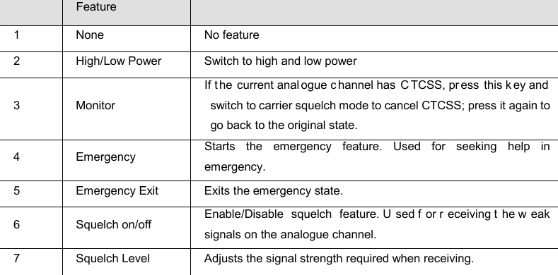
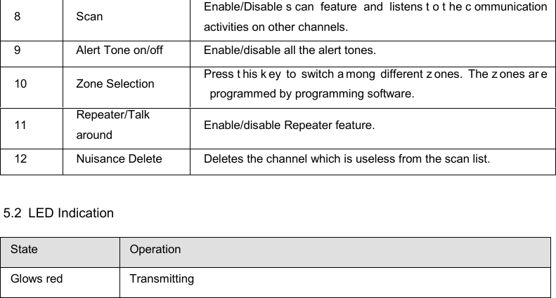
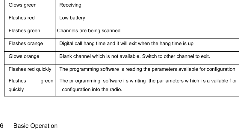
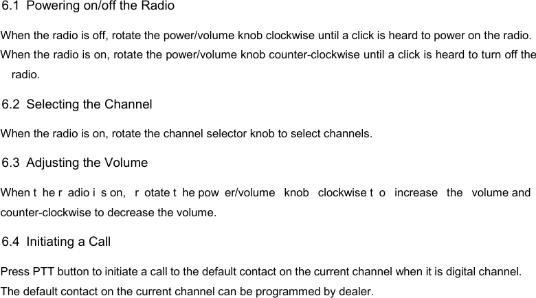
User Manual
Discussion / Help
Navigation