Kirisun Communication DP990 DMR Two Way Radio User Manual
Kirisun Communications Co., Ltd. DMR Two Way Radio
User Manual

DP990 DMR Two Way Radio User Manual
III
User Manual
DP990
DMR Two Way Radio
We are very grateful for your purchasing Kirisun brand two-way radio produced by Kirisun
Communications Co., Ltd
We believe Kirisun two-way radio, which always incorporates the latest technology, can bring
great convenience to your life and work. We also believe that the quality and function of
Kirisun two-way radio can meet your demands for reliable communication.

DP990 DMR Two Way Radio User Manual
Notice
◆ Please carefully read this instruction manual before using the product for your easy
operation. We will consider that you have read this manual when you use the product.
◆ Please carefully keep the manual for future reference.
◆ In order to protect your legal rights from infringement, please carefully fill in the warranty
card and claim valid receipt.
◆Kirisun and our authorized partners own the intellectual property of all the parts of this
product (including accessories). Any design and materials may not be modified, copied,
extracted or translated without authorization of Kirisun or its authorized parities.
◆This product may involve update or modification in future, and Kirisun owns the right to
change the specifications of software and hardware described in this manual without further
notice. Specifications and information contained in this manual are for reference only.
◆ All the contents are carefully proofread, but mistake may be inevitable. The rights of final
explanation are preserved by Kirisun.

DP990 DMR Two Way Radio User Manual
Safety Precaution
◆The radio can only be repaired or maintained by professional technicians. The user must not
disassemble the radio at liberty.
◆In order to avoid problems caused by electromagnetic interference or electromagnetic
incompatibility, please turn off the radio in the place such as hospital, plane and other health
care centers where there is a sign such as “Turn off Your Radio”.
◆In the car with air bags, please do not keep your radio at the place within possible reach of
the air bag spread.
◆Please turn off your radio before entering flammable or explosive environment.
◆ Do not change or charge the battery in flammable or explosive environment.
◆ Please turn off your radio when getting closer to the blast zone or thunder zone.
◆Do not use any radio with damaged antenna, which may cause slight burning to the skin in
contact.
◆Please make sure that the antenna is properly attached when using the radio.
◆Please keep the radio vertical when it is transmitting, and also keep the microphone 5 cm
away from your mouth.
◆Please make sure that the antenna is 2.5cm away from your body when the radio is
transmitting.
DP990 DMR Two Way Radio User Manual
Battery
◆If the conductive substance on human body makes contact with the exposed battery terminal,
it may damage your belongings, and/or do harm, such as burning, to human body. Conductive
material includes jewelry, keys or bead-like necklace. They can form a loop (it causes short
circuit) with battery and cause skin burn after the rapid temperature rise. Be cautious when
managing a charged battery, especially when you put it in the pocket, wallet or container with
metallic objects. To decrease the risk of being harmed, the battery cannot be exposed in the
file, disassembled or squeeze.
◆ The highest environment temperature around the power supply device or voltage
transformer must not be higher than 40°C (104°F).
◆ Please turn off the radio attached with battery when charging. Using radio during charging
will affect its charging process.
◆ Please do not put the radio and battery into the charger when they are not in need of
charging, and constant charging will shorten the battery life. Do not use the charger as a store
to radio.
◆ To achieve optimal performance, we recommend changing battery after one-year use.

DP990 DMR Two Way Radio User Manual
Content
1 UNPACKING AND CHECKING ................................................................................... - 2 -
2 BATTERY INFORMATION ........................................................................................... - 3 -
3 INTRODUCTION............................................................................................................ - 7 -
4 BASIC OPERATION ..................................................................................................... - 9 -
5 INITIATING/RECEIVING A CALL .............................................................................. - 13 -
6 SHORT MESSAGE ..................................................................................................... - 14 -
7 EMERGENCY .............................................................................................................. - 19 -
8 CALL LOG ................................................................................................................... - 21 -
9 GENERAL SETTING ................................................................................................... - 23 -
10 ADVANCED FEATURES ........................................................................................ - 29 -
11 TROUBLESHOOTING ............................................................................................. - 40 -

DP990 DMR Two Way Radio User Manual
1 Unpacking and Checking
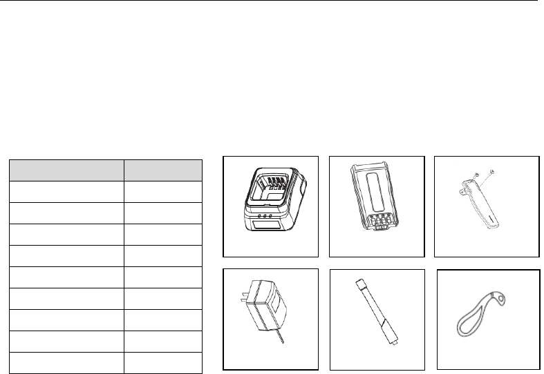
Please carefully open the box, and check if the accessories listed below are contained in the package. For
any missed or damaged item, please contact your local dealer for solution.
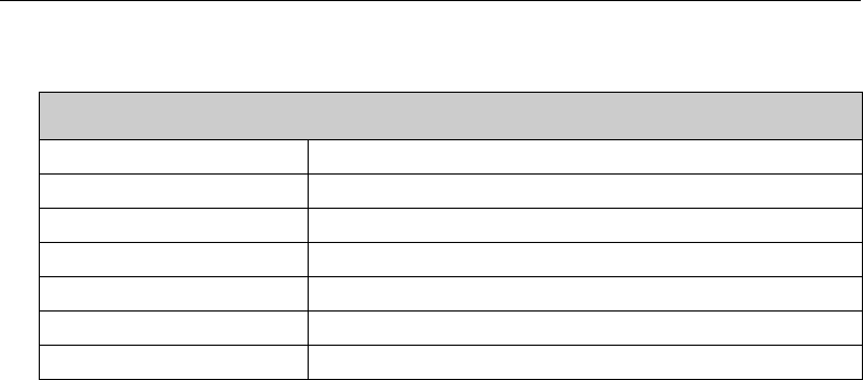
1.1 Supplied Accessories
Material
Quantity
Radio
1
Charger
1
Power Adaptor
1
Battery
1
Belt Clip
1
Antenna
1
Strap
1
Certificate
1
User Manual
1
Strap
Belt clip + Screw
Charger
Battery
Antenna
Power Adaptor
DP990 DMR Two Way Radio User Manual
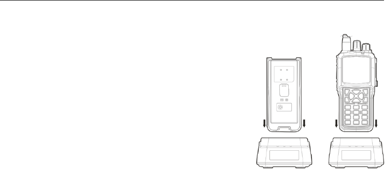
2 Battery Information
2.1 Battery Charging
1) Plug the power adaptor in the proper socket of AC power.
2) Plug the cable of the power adaptor at the back of the socket,
and the green indicator glows.
3) Plug the battery or radio in the charger
Make sure that the battery is in proper contact with the charger
terminal, and the red indicator glows.
4) After the battery is charged for 5 hours, the red light goes out,
indicating that the battery is fully charged.
When the green indicator glows, keep the battery on the charger
for 1-2 hours before taking it out so as to achieve the optimal
performance.
5) Take out the power adaptor from the socket of AC power output.
Note:
The battery is not charged before delivery from the factory, so please charge the battery before
your first use.
If the battery which is stored for over 2 months or a new battery is charged for the first time,
DP990 DMR Two Way Radio User Manual
it should be charged repeatedly to gain full battery capacity. The battery should be at least
charged once every three months.
When the battery is fully charged or the battery power is above the level of low power alert,
do not charge the battery, or it may affect the battery life and performance. Please take out
the battery from the charger after it is fully charged.
When the radio enters the state of low voltage alarm, please charge the battery before using
it and do not force to power on the radio in case that the battery life and performance is
impaired.
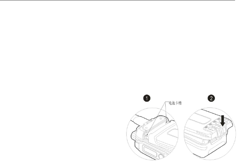
2.2 Attaching the Battery
As shown in ①, align the battery with the main unit
and push it from the bottom . Press the battery until
a click is heard as shown in ②
DP990 DMR Two Way Radio User Manual
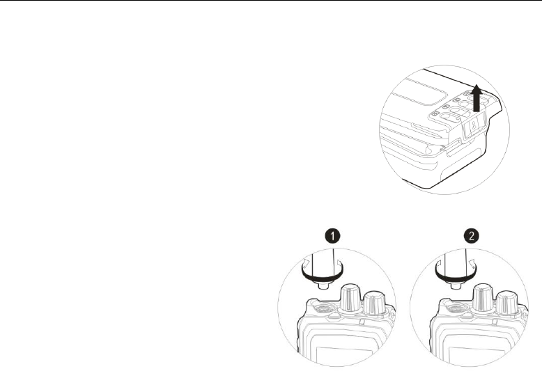
2.3 Detaching the Battery
For detaching the battery, please turn off the radio. As shown on the
right picture, lift the battery latch to bounce the battery, and slide the
battery downwards to take it out.
Note:
Do not throw the battery terminals with short circuit or
battery into fire.
Do not remove the battery case without permission.
2.4 Attaching the Antenna
As shown in ①, align the antenna with the
interface at the radio top, and turn it clockwise to
fasten.
For detaching the antenna, turn the antenna
counter-clockwise as shown in ② to take it out.
DP990 DMR Two Way Radio User Manual
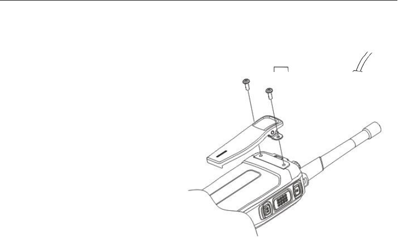
2.5 Attaching the Audio Accessories
Connect the audio accessory in the port
and fix it with screw
2.6 Attaching the Belt Clip
Align the two screw holes in the belt clip
with the holes at the back of the radio,
and fix them together with screws.
Loosen the screws to detach the belt
clip.
DP990 DMR Two Way Radio User Manual
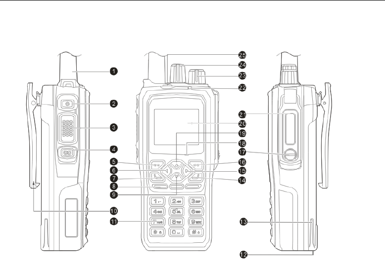
3 Introduction
DP990 DMR Two Way Radio User Manual
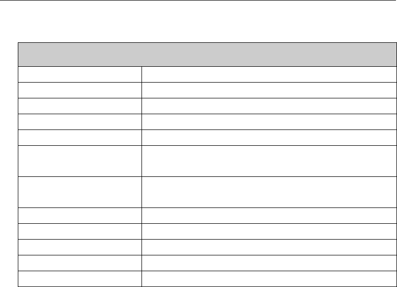
No.
Part Name
No.
Part Name
No.
Part Name
1
Antenna
10
Belt Clip
19
Up Key
2
Side Key 1
11
Digital Key
20
LCD Display Screen
3
PTT Key
12
Battery Latch
21
Comm Port
4
Side Key 2
13
Battery
22
LED Indicator
5
Menu/OK Key
14
Hang-up /Menu Key
23
Power/Volume Knob
6
Left Key
15
Right Key
24
Channel Selector Knob
7
Dial Key
16
Return Key
25
Top Key
8
Speaker
17
Cover Screw
-
-
9
Down Key
18
Microphone
-
-

DP990 DMR Two Way Radio User Manual
4 Basic Operation
4.1 Powering on/off
To power on the radio, turn the power/volume knob clockwise until a click is heard; the LCD screen
displays the power-on image and the backlight is on automatically; an alert tone and a sligt vibrating hint
(created by motor)will sound and shake at the same time .
To power off the radio, turn the power/volume knob counter-clockwise until a click is heard
4.2 Adjusting the Volume
When the radio is on, turn the power/volume knob to adjust the volume. Turn it clockwise to increase the
volume and counter-clockwise to decrease
After turning the power/volume knob counter-clockwise to the minimum volume, and keep turning it until a
click is heard.
4.3 Selecting the Zone
Zone is a group of channels. You can put channels of the same kind into a zone and you can quickly switch
to different channel group in different working environment. It supports a maximum of 248 zones, and
each supports a maximum of 128 channels.
1) Press to enter the manual.
2) Select and enter “ zone menu.
3) Press【Up】/【Down】 key to select the target zone.

DP990 DMR Two Way Radio User Manual
4) Press【OK】 key to switch to the selected zone.
4.4 Selecting the Channel
Turn the channel selector knob to select channel
Each channel can be configured as analogue or digital. Turn the channel selector knob to switch between
digital and analogue channel.
When the channel is switched from digital to analogue, certain features are no longer available such as
short message and etc.
4.5 PTT Key
The PTT key has two basic applications below:
1) The PTT key can transmit signals to other radios when the radio is calling
2) The PTT key can initiate a new call when the radio is not calling.
Note:
Press PTT key to talk during a call
Release PTT key to receive and wait for calls.
When other radio is calling, you cannot press PTT key to transmit.
4.6 Menu Operation
5) Press to visit menu.
6) Press to select menu item.
DP990 DMR Two Way Radio User Manual
7) Press to enter the menu item
8) Press to return to the last menu or the main interface.
9) Press to return to the main interface.
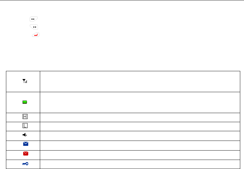
4.7 Icon
Signal strength
More bars indicate stronger signal and less bars weak signal. It only show up when
receiving.
Battery indicator
Less space indicates more battery power. When the battery is low, the icon will turn
red
High power
Low power
Mute
Unread message
Full mailbox
Keypad lock
DP990 DMR Two Way Radio User Manual
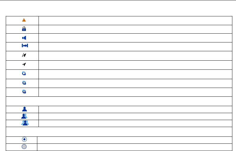
Emergency
Encryption
Man Down
Talkaround
GPS is receiving
GPS positioned
Icon whirling indicates it is scanning
The scan stays on priority channel 1
The scan stays on priority channel 2
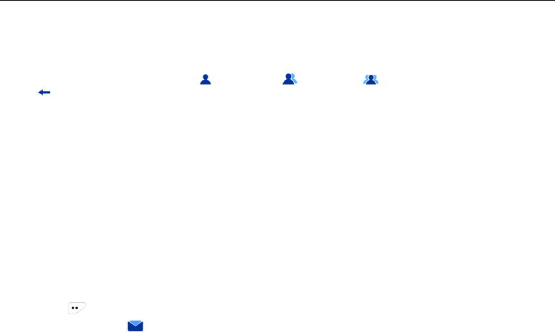
IDType:
Private call
Group call
All call
Menu Selection:
Selected
Not selected

DP990 DMR Two Way Radio User Manual
4.8 LED Indication
Red Indicator glows:the radio is transmitting.
Green Indicator glows: the radio is receiving signals (speech message, text message and data) or it
detected activity on the channel.
Orange indicator glows: orange indicator glows during the call hang time in digital mode or auto reset time
in analog mode.
Orange indicator flashes: the radio is in emergency state or is receiving emergency alarm; missed call alert;
the radio is scanning; the radio is roaming.
Red indicator flashes: the radio is in low power.
5 Initiating/Receiving a Call
5.1 Initiating a call to the default contact
If default contact is preset on the current channel, you can press the PTT key direct to initiate a call to the
default contact
You can preset a default contact on each digital channel via dealer
5.2 Selecting the Contact and Initiating a Call
Enter the “contact” menu and select a contact in the contact list; press the PTT key to talk
5.3 Dialing Manually and Initiating a Call
Enter the contact menu and select “manual dial” to enter the call ID before pressing PTT key to initiate a
call.
DP990 DMR Two Way Radio User Manual
5.4 Receiving/Responding to a Call
1) LED indicator glows.
2) LCD displays icon of call type ( private call, group call, all call), alias or ID and incoming
icon .
3) Broadcasts received call.
4) You can press the PTT key during the call hang time to call the current contact.
Note:
For receiving call from group, the radio must be a member of the group (set by dealer with programming
software).
6 Short Message
The radio can receive/transmit short message and the message supports a maximum of 300 characters
6.1 Edit and send short message
1) Press to enter menu.
2) Select and enter “ short message” menu.
3) Select “New Message” and enter the editing interface.
4) In the editing interface, you can:
a) The cursor indicates the current editing position.

DP990 DMR Two Way Radio User Manual
b) Enter text contents through keypad.
c) Press to move the cursor to the right/left.
d) Press【#】 key to switch typewriting and 【*】 key to switch to lower/upper case.
e) In the non-digital input mode, press【1】 key to enter punctuation.
f) Press the delete key to delete the character right before the cursor.
5) Press OK key after the message is edited and send, save or delete the message.
6) Select “send” and enter the “contact” interface.
7) Select contact list and enter the list.
8) Select the target contact and press OK key to send message; or you can select manual dial in the
contact interface and enter the target number and press OK key to send the edited message.
9) After the message is sent, “Message Sent” indication will show on the LCD screen and the radio will
return to the short message interface.
If the message failed to deliver, ”Message Failed” will show on the LCD screen and the radio returns to the
short message interface.
The sent message is saved in the sent mailbox。
6.2 Sending Quick Message
The radio supports a maximum of 10 quick messages (message is edited by dealer through programming
software)
You can edit the pre-defined quick message before sending it.
1) In the home screen, press and enter the menu.
2) Select and enter “ short message” menu.

DP990 DMR Two Way Radio User Manual
3) Select “template” and enter quick message list.
4) Select the target quick message in the list and press OK key to enter the editing interface.
You can edit the quick message.
1) Press OK key to send, save or delete the edited message.
2) Select “Send” and enter the “Contact” interface.
3) Select the contact list and press OK key to enter.
4) Select the target contact and press OK key to send the edited message. Or you can select “Manual
Dial” in the “Contact” interface and enter the target contact number before pressing OK key to send it.
5) When the quick message is successfully sent, “Message Sent” will show on the LCD screen and then it
returns to the message list interface.
If the message failed to deliver, “Message Failed” will show on the LCD and then it returns to the message
list interface.。
The sent message will be saved in the outbox。
6.3 Sending Status Message
If the radio supports status message feature, you can receive and transmit status code which is agreed on
with other radios.
The radio supports a maximum of 1024 status messages (programmed by dealer).
1) Press to enter the menu in the home screen.
2) Select and enter “ short message” menu.

DP990 DMR Two Way Radio User Manual
3) Select “Status Message” and enter status message list.
4) Select the target status message and press OK key to enter the interface of status message.
5) Press “Send” key and enter the “Contact” interface.
6) Select “Contact List” and press OK key to enter the contact list interface.
7) Select the target contact and press OK key to send the selected status message.
Or you can select “Manual Dial” in the “Contact” interface and enter the target contact number before
pressing OK key to send the message.
8) After the status message is sent, “Message Sent” will show on the LCD screen and then it returns to
the message list interface.
If the status message failed to deliver, “Message Failed” will show on the LCD screen and then it returns to
the interface of status message.
The sent status message is saved in outbox.
6.4 Receiving Short Message
When the radio receives a message, the LCD will remind you of the new message and display the icon of
unread message on the status bar.
You can enter inbox and read message.
1) Press to enter the menu in the home screen.
2) Select and enter “ short message” menu.
3) Select “inbox” and enter.
4) Select an unread message and press OK key to read the message.

DP990 DMR Two Way Radio User Manual
6.5 Deleting Short Message
You can delete the message that is sent, received or saved.
6.5.1 Deleting the Message by Batch
1) Press to enter the menu.
2) Select and enter “ short message” menu.
3) Select “Delete Message” and enter the interface.
4) Select the mailbox of the message to be deleted (inbox, outbox or draft box) and press OK key to
delete the message in the box.
Or you can select “Delete All” to delete all the messages.
6.5.2 Deleting the Message Individually
1) Select the target message in one box (inbox, outbox or draft box) and delete.
2) Press the option key to check details and to save or delete the target message.
3) Select “Delete”.
4) Press OK key to delete.

DP990 DMR Two Way Radio User Manual
7 Emergency
During emergency, you can send a confirmed emergency alarm and an emergency voice message to the
specified radio group. You can initiate an emergency alarm anytime even when it is receiving signals.
The radio supports three kinds of emergency alarm mode.
Emergency Alarm
Emergency Alarm and Emergency Call
Emergency Alarm and Auto Background Tone
There are alarm types below:
1) Siren Only—— after the radio enters the emergency state, the siren only sounds locally and the control
center will not receive any alarm signal.
2) Conventional—— the radio sends emergency alarm and audio/visual alert.
3) Secret —— the radio sends emergency alarm but no audio/visual alert; the speaker will not turn on
when receiving speech signal until the PTT button is pressed to talk.
4) Secret with Voice—— the radio sends emergency alarm and it receives call but no audio/visual alert
until the PTT button is pressed.
In addition, when the alarm type is set as “Siren Only” and after the radio enters the emergency state, the
siren will only sound locally and the control center will not receive any alarm signal.
7.1 Sending Emergency Alarm
1) Press the programmable button which is programmed as “Emergency” and enter the emergency state;
the icon will show in the status bar; the LCD displays the emergency group call alias or ID. Emergency

DP990 DMR Two Way Radio User Manual
icon is and the outgoing call icon is .
2) When the radio receives response, the LCD will show “Emergency Alarm Succeeded”.
If the radio failed to receive response and when the retry count is used up, the LCD will show “Emergency
Alarm Failed”。
3) The radio exits the emergency mode and returns to the home screen.
Note:
If you radio is set as “Secret” or “Secret with Voice”, there will be no audio/visual alert.
After the emergency alarm with voice responded, the two parties can communicate on the emergency
channel.
The emergency with voice will then open the radio mic, which allows user to talk without having to
press PTT button. The automatic mic activation is called Hot Mic (set by dealer with programming
software).
7.2 Receiving Emergency Alarm
If the radio enabled “Emergency Indication” feature, it can receive emergency alarm. Otherwise, the
emergency alarm will be ignored (set by dealer through programming software).
For receiving emergency alarm, the radio must be set as a group member(set by dealer through
programming software).
1) When the radio receives emergency alarm, the LCD status bar will show the emergency icon .
2) The LCD displays the alias or ID of the emergency radio. The radio periodically sounds the alarm alert
and the red LED flashes quickly. Press any key to cancel the emergency alarm..

DP990 DMR Two Way Radio User Manual
7.3 Exiting Emergency Alarm
The radio will exit the alarm mode under the circumstances listed below:
Receives emergency alarm response on Emergency alarm mode.
The emergency alarm retry count is used up and no response is received.
Press and hold the programmable button programmed as “Emergency Exit”
8 Call Log
Through the call log, you can check and manage recent outgoing call, incoming calls and missed calls onthe
radio. The call log records private call only.
8.1 Checking Latest Call
1) Press in the home screen to enter the menu.
2) Select and enter “ call log” menu.
3) Select the call log (missed calls, outgoing calls and incoming calls)and enter the interface.
4) Select and enter the call list(missed calls, outgoing calls and incoming calls).
5) Select the target call log. Press OK key to check, save or delete the target record.
6) Select “Details” and press OK key to check the record details.
7) Press PTT key to call the contact on the record.
8.2 Saving ID in the Contact List
1) Select the target record in the call list.

DP990 DMR Two Way Radio User Manual
2) Select the target record which needs to be saved and you can press OK key to check, save or delete
the target record.
3) Select “Save” and enter the interface for adding contact.
4) Enter the contact name.
5) Press Ok key to save the contact..
8.3 Deleting Call from the Call List
8.3.1 Deleting all the Records from the List.
1) Press in the home screen to enter the menu.
2) Select and enter “ call log” menu.
3) Select the call log(missed calls, outgoing calls and incoming calls)and enter the interface.
4) Select “Delete All”.
5) Press Ok key to delete all the records in the list.
8.3.2 Deleting Individual Record
1) Select the target record in the call list.
2) Press OK key to check, save or delete the target record.
3) Select “Delete”。
4) Press OK key to delete the record.

DP990 DMR Two Way Radio User Manual
9 General Setting
9.1 Language Selection
You can switch the radio languages.
1) Press in the home screen to enter the menu.
2) Select and enter “setting” menu.
3) Select “Language Selection” and enter the interface.
4) Select the language and press OK key for switching to the language.
9.2 Alert Tone Setting
You can enable/disable the alert tone and adjusts the volume.
9.2.1 Enable/disable the Alert Tone
1) Press in the home screen to enter the menu.
2) Select and enter “ setting” menu.
Select “Alert Tone Setting” and enter the interface for alert tone setting:
“All Alert Tone Off” – disables all the alert tones.
“All Alert Tone On” –enables all the alert tones.
“Outgoing Alert Tone” – enables/disables the outgoing alert tone.
“Private Call Alert Tone” – enables/disables the alert tone of receiving private call.
“Group Call Alert Tone” – enables/disables the alert tone of receiving group call
“Key Alert Tone” – enables/disables the key alert tone.

DP990 DMR Two Way Radio User Manual
“Information Alert Tone” – enables/disables the alert tone of receiving short message.
“Finished Call Alert Tone” – enables/disables the alert tone of finished call.
Press OK key and the LCD will show “Operation Succeeded” and save the alert tone.
9.2.2 Adjusting the Volume of Alert Tone
1) In the alert tone setting interface, select and enter the “Alert Tone Volume” interface.
2) Press【Up】 key or 【Left】 key to increase the alert tone volume. Press【Down】 key or 【Right】
key to decrease the volume.
3) Press OK key and the LCD shows “Operation Succeeded” . The alert tone volume will be saved.
9.3 Vibration Setting
You can enable/disable the vibration feature.
1) Press in the home screen to enter the menu.
2) Select and enter “ setting” menu.
3) Select “Vibration Setting” and enter the interface.
You can enable/disable the vibration alerts below:
“All Vibration Off” –disable vibration of all types.
“All Vibration On” – enable vibration of all types.
“Call Alert” – enables/disables the vibration call alert.
“Incoming Call” – enables/disables the vibration alert of private call.
“Short Message” – enables/disables the vibration alert of receiving short message.
“Emergency Alarm”- enables/disables the emergency vibration alert.

DP990 DMR Two Way Radio User Manual
4) Press OK key and the LCD will show “Operation Succeeded”. The vibration alert will be saved.
9.4 Power Level Setting
You can set high/low power for each channel.
1) Press in the home screen to enter the menu.
2) Select and enter “ setting ” menu.
3) Select “Power Setting” and enter the interface.
4) Select “High” or “Low” power and set the power level.
5) Press OK key and the LCD will show “Operation Succeeded”. The power level will be saved.
9.5 Keypad Lock Setting
You can lock the radio keypad in case of incorrect operation.
9.5.1 Manually Locking the Keypad
1) Press in the home screen to enter the menu.
2) Select and enter “ setting” menu.
3) Select “keypad lock setting” and enter the interface.
4) Select “Locking Keypad”。
5) Press OK key and the LCD will show “Operation Succeeded” . The keypad is locked.
9.5.2 Automatically Locking the Keypad
1) In the keypad lock interface, select and enter the interface of “Auto Lock”.
2) Select the delay time of auto keypad lock.

DP990 DMR Two Way Radio User Manual
3) Press OK key and the LCD will show “Operation Succeeded”. The auto lock time is saved.
During the set time, the keypad will be locked automatically if no operation is performed on it.
9.5.3 Locking the Keypad Quickly
Press 【*】key in any interface to lock the keypad.
9.5.4 Unlocking the Keypad
When the keypad is locked, press and then 【*】key to unlock the keypad.
9.6 Screen Brightness Setting
You can adjust the brightness of the screen based on different situation.
1) Press in the home screen to enter the menu.
2) Select and enter “ setting” menu.
4) Select “Brightness” and enter the interface.
5) Press【Up】 key or 【Left】 key to increase the brightness; press【Down】 key or 【Right】key to
decrease the brightness.
6) Press OK key and the LCD will show “Operation Succeeded”. The brightness setting will be saved.
9.7 Screen Backlight Setting
You can set the backlight duration of the screen based on different situation to save battery power.
1) Press in the home screen to enter the menu.
2) Select and enter“setting” menu
3) Select “Backlight” and enter the interface.。

DP990 DMR Two Way Radio User Manual
4) Select the backlight duration for the screen.
5) Press OK key and the LCD will show “Operation Succeeded”. The time setting for turning off the screen
will be saved.
During the set time, the radio will turn off the screen if no operation is performed. Press any key to restore
the brightness。
9.8 Indicator Setting
You can turn on/off the LED indicator based on different situation.
1) Press in the home screen to enter the menu.
2) Select and enter“setting” menu.
3) Select “LED indication” and enter the interface.
4) Select “On” or “Off” and turn on/off the indicator.
5) Press OK key and the LCD will show “Operation Succeeded”. The LED indication setting is saved.
9.9 Talk Around/Repeater Setting
You can switch the work mode based on different situation (talk around or repeater mode).
1) Press in the home screen to enter the menu.
2) Enter the“ setting” interface.
3) Select “Talk Around/ Repeater” and enter the interface.
4) Select “Talk Around/ Repeater” and switch work mode.
5) Press OK key and the LCD will show “Operation Succeeded”. The work mode will be saved.

DP990 DMR Two Way Radio User Manual
9.10 Squelch Level Setting
You can adjust the squelch level based on different situation to remove unnecessary calls in weak signals。
This setting is valid on analogue channel.
1) Press in the home screen to enter the menu.
2) Select and enter “ setting” menu.
3) Select “Squelch Level” and enter.
4) Press【Up】 key or【Left】 key to increase the squelch level and 【Down】 key or 【Right】 key to
decrease the squelch level.
5) Press OK key to save the squelch level and return to the setting interface.
9.11 Checking Radio Information
You can check information such as radio ID, serial number, firmware version, hardware version and
vocoder.
1) Press in the home screen to enter the menu.
2) Press and enter “ setting” menu.
3) Select and enter the “Radio Information” interface

DP990 DMR Two Way Radio User Manual
10 Advanced Features
10.1 Radio Check
Radio Check feature is used to check whether the target radio is activated in the system. The target user
will automatically send a response to the caller radio without any audible or visual indication.
1) Press in the home screen to enter the menu.
2) Select and enter“ contact” menu.
Or you can press in the home screen to directly enter the “Contact” menu.
3) Select and enter the “Contact List” interface. Select the target private call contact for radio check.
4) Press OK key and enter the “Contact” interface.
5) Select “Radio Check” and confirm.
The screen will show the alias or ID of the target private call contact and indicates that the radio is sending
radio check; the red indicator glows.
6) Waiting for response from the target radio
If the target radio is activated in the system and it succeeded to respond, the radio will show “Radio
Available”.
Note:
If you press during radio check, the radio will exit the radio check process.
If the retry count is used up and no response is received, the radio will exit the radio check and show
“Radio Unavailable”

DP990 DMR Two Way Radio User Manual
10.2 Call Alert
Call Alert feature allows the caller radio to request the target radio to call back.
10.2.1 Receiving and Responding to Call Alert
1) When the radio received call alert, it will automatically reply if call alert decode is enabled.
The LCD shows “Call Alert…” , the alias or ID of caller radio.
The radio periodically sounds alert tone and orange LED is flashing.
2) Press 【PTT】key to respond to the caller radio or any other key to ignore the call alert.
10.2.2 Initiating Call Alert
1) Press in the home screen to enter the menu.
2) Select and enter “ contact ” menu.
Or you can press in the home screen and directly enter “Contact” Menu.
3) Select and enter “Contact List” interface. Select the target private call contact.
4) Press OK key and enter the “Contact” interface.
5) Select “Call Alert” and confirm.
The LCD screen displays the alias or ID of the target radio and indicates that the radio is sending call alert;
the red LED glows.
6) Waiting for response from the target radio.
If the target radio succeeded to respond, the caller radio show “Call Alert Succeeded” on the screen, or it
shows “Call Alert Failed”.

DP990 DMR Two Way Radio User Manual
Note:
If you press when sending “call alert”, the radio will exit the call alert mode.
If the retry count is used up and no response is received, the radio will automatically stop sending call
alert and display “Call Alert Failed” on the screen.
10.3 Radio Stun/Un-stun
Stun/Un-stun feature allows the radio to stun/un-stun the target radio through air signaling. The stunned
radio cannot transmit nor receive and it can only be activated by un-stun signaling of the authorized radio.
This feature is used to prevent from being used without authorization or used by others when lost.
10.3.1 Receiving Stun/Un-stun Signaling
After the target radio receives the stun/un-stun signaling and succeeded to be stunned / un-stunned, it will
automatically send operation success indication to the caller radio.
The radio which is stunned can only display channel alias and group alias when it returns to the home
screen without the ability to receive all the other information except the un-stun signaling. All the operation
on the radio is valid except powering on/off.
After the target radio receives the un-stun signaling and succeeded to be un-stunned, it will automatically
send operation success indication to the caller radio.
The activated radio will go back to normal from being stunned.
10.3.2 Sending Stun and Un-stun Signaling
1) Press in the home screen to enter the menu.
2) Select and enter “management feature” menu.

DP990 DMR Two Way Radio User Manual
3) Select “Stun/Un-stunned”.
4) Enter “Contact List” and select the target private call contact.
The screen shows the alias or ID of the target radio and the radio indicates that it is sending stun/un-stun
signaling. The red indicator glows.
5) Waiting for response from the target radio.
If the response from the target radio is received, the screen will show “Stun Succeeded”/“Un-stun
Succeeded”, or it shows “Stun Failed”/“Un-stun Failed”.
Note:
If you press in the process of sending signaling, the radio will stop sending stun/un-stun signaling.
If the retry count is used up and no response is received, the radio will automatically stop sending
signaling and indicate that the transmission failed.
10.4 Radio Kill
Kill feature allows the user to kill the target radio through air signaling. After the target radio is killed, the key
configuration data will be cleared and the radio is powered off automatically. You cannot operate the radio
after powering it on.
The killed radio can only be revived by the authorized dealer or supplier.
This feature is used to prevent the lost radio from being used and the key configuration data from being
stolen.

DP990 DMR Two Way Radio User Manual
Note:
Once the radio is killed, the configuration data will be lost and the radio cannot go back to normal after
reboot, so please operate with due care!
The killed radio can only be revived by authorized dealer or supplier.
10.5 Remote Monitor
Remote Monitor allows the user to turn on the microphone of the target radio through air signaling. There will
be no audible or visual indication on the target radio. You can use this feature to monitor the surroundings of
the target radio.
1) Press in the home screen to enter the menu.
2) Select and enter “ management” menu.
3) Select “Remote Monitor”.
4) Enter “Contact List” and select the target private contact.
The screen displays the alias or ID of the target radio and indicates that the radio is sending remote control
signaling. The red indicator glows.
5) Waiting for response from the target radio.
If the response from the target radio is received, the screen shows “Remote Control Succeeded”, or it
shows “Remote Control Failed”.

DP990 DMR Two Way Radio User Manual
Note:
If you press when the radio is sending remote monitor signaling, it will stop and exit the remote
monitor mode.
If the retry count is used up and no response is received, the radio automatically exits the mode and
shows”Remote Control Failed”.
10.6 Scan
In order to receive voice and data from multiple channels, the radio can be programmed to scan these
channels. The radio supports up to a maximum of 128 scan lists and each scan list supports a maximum of
16 channels. Mixed scan of analogue and digital channels are available. You can relate different channel to
different scan list.
By editing the scan list, you can add or delete the channels on the scan list and set priority channel.
10.6.1 Checking the Scan List
1) Press in the home screen to enter the menu.
2) Select and enter “ Scan” menu.
3) Select “Checking Scan List” to check the members on the list ( represents priority channel 1;
represents priority channel 2; represents conventional channel).
Note:
If priority channel is set, the priority icon will be displayed on the right of the member alias, indicating that
the member is on priority channel 1/priority channel 2. It can’t be multiple priority channel 1 or priority
channel 2 on the same scan list. If there is no priority channel, the icon indication will not exist.

DP990 DMR Two Way Radio User Manual
10.6.2 Editing the Scan List
1) Press in the home screen to enter the menu.
2) Select and enter “ Scan” menu.
3) Select “Editing Scan List”.
You can operate as below on the scan list:
Add: add the target channel to the scan list.
Delete: delete the target channel from the scan list.
Editing Priority: set the channel priority on the scan list.
10.6.3 Enabling/disabling Scan
1) Press in the home screen to enter the menu.
2) Select and enter “ Scan” menu.
3) Select “Scan Switch”.
4) Select to enable/disable scan
Note:
During the scan, the radio receives data (short message, GPS, telemetry or PC data) and digital signaling
only on the selected channel.
10.6.4 Responding during Scan
During the scan, when the radio detected a channel with activity, it will stay on this channel for certain time,
and the time is called the scan hang time (programmed by dealer through programming software).
1) Keep your mouth 1-2 inches from the microphone.
2) Press PTT button during the scan hang time and the red indicator glows.

DP990 DMR Two Way Radio User Manual
3) Wait for the alert tone of transmission permission to end and speak to the microphone.
4) Release PTT key to receive.
5) If you did not respond during the scan hang time,the radio will go on to scan other channels.
10.7 Man Down
1) Press in the home screen to enter the menu.
2) Select and enter “ Application” menu.
3) Select “Man Down” and enter the interface.
4) Select “On” or “Off” to enable/disable Man Down.
10.8 VOX
If VOX is enabled on the radio, you can directly speak to the microphone and transmit without having to
press PTT button.
You can enable/disable VOX through the menu and adjust the microphone sensitivity.
10.8.1 Enabling/Disabling VOX
1) Press in the home screen to enter the menu.
2) Select and enter “ Application” menu.
3) Select “VOX” and enter “VOX” interface.
4) Select and enter the “VOX Switch” interface.
5) Select “On” or “Off” to enable/disable VOX.
10.8.2 Adjusting VOX Level
1) Press in the home screen to enter the menu.

DP990 DMR Two Way Radio User Manual
2) Select and enter“ Application” menu.
3) Select “VOX” and enter “VOX” interface.
4) Select and enter “VOX Level” interface.
5) Press【Up】key or【Left】key to increase VOX level or【Down】key or【Right】key to decrease VOX
level.
6) Press OK key and save the VOX level and return to the VOX setting interface.
10.9 GPS
If GPS is enabled, the radio will display the location information and offer location information to the
software server (set by dealer through programming software).
10.9.1 Checking the Current Location
1) Press in the home screen to enter the menu.
2) Select and enter “ Application” menu.
3) Select “GPS” and enter “GPS” interface.
4) Select and enter “GPS interface” interface to check information such as date, time, longitude, latitude,
and satellite number.
10.9.2 Enabling/disabling GPS
1) Press in the home screen to enter the menu.
2) Select and enter “ Application” menu.
3) Select “GPS” and enter the interface.

DP990 DMR Two Way Radio User Manual
4) Select and enter “GPS Switch” interface.
5) Select “On” or “Off” to enable/disable GPS.
10.9.3 Enabling/disabling GPS
1) Press in the home screen and enter the menu.
2) Select and enter “ Application” menu.
3) Select “GPS” and enter “GPS” interface.
4) Select and enter “GPS Report On/Off” interface.
5) Select “On” or “Off” to enable the GPS Report feature.
10.10 Time
1) Press in the home screen to enter the menu.
2) Select and enter “ Application” menu.
3) Select “Time” to set the display status and format of time and date.
10.11 Network
1) Press in the home screen and enter the menu.
2) Select and enter “ Application” menu.
3) Select “Network” and check the transmitting and receiving frequency on the current channel.

DP990 DMR Two Way Radio User Manual
10.12 Bluetooth
1) Press in the home screen and enter the menu.
2) Select and enter “ Bluetooth” menu.
3) Select “Bluetooth Switch” and enter the interface.
4) Select “Enable Bluetooth” or “Disable Bluetooth” to enable/disable Bluetooth.
5) After the bluetooth is enabled, go back to the Bluetooth menu and select “Device Available”.
6) Select “Search Device” to search for device that matches.
7) Select “Connect”.

DP990 DMR Two Way Radio User Manual
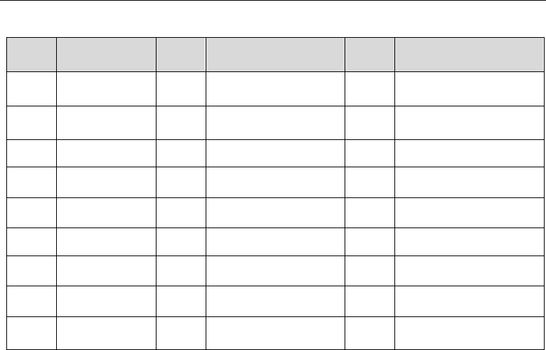
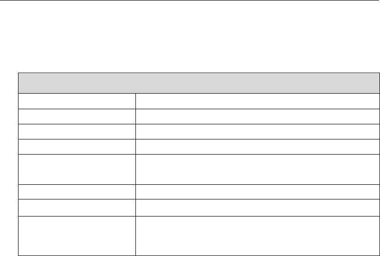
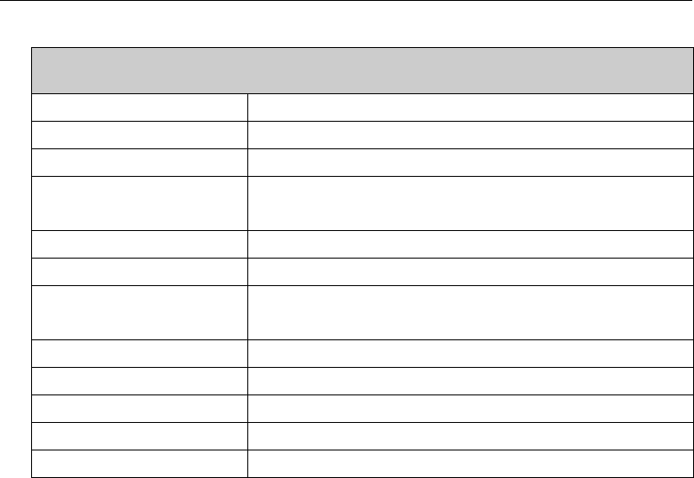
11 Troubleshooting
No.
Troubleshooting
Causes and Solutions
1
Failed to power on
A.Check if the battery is used up –charge the battery or change it if
the power is out.
B. Check if the power connecting pole is in proper contact with
battery –try again after re-attachment.
C. Check if the battery contact is contaminated or in poor contact
–clean the contact.
2
Communication
failed
A. Inconsistent frequency between radios – select a channel with
the same frequency.
B. Different CTCSS/CDCSS signaling –re-set with PC.
C. Beyond communication scope.

DP990 DMR Two Way Radio User Manual
3
Failed to receive
signals
A. Poor antenna contact – fix the antenna.
B. Wrong RX/TX frequency – select the same TX/RX frequency.
C. Beyond communication scope.
4
The green indicator
glows but no sound
is received
A. Check if the volume is at its lowest level – increase volume.
B. Check if the speaker is broken - change the speaker.
5
GPS failed to locate
A. Check if the antenna is dual mode - change to a dual-mode
antenna.
B. Check if GPS is properly set – reset GPS.
C. The radio is placed in a blocked environment - place it in an
open location.
6
Abnormal
programming
A. Improper connection – check cable connection.
B. PC USB driver is not installed - install the driver.
C. The earpiece interface is in poor contact - change the
interface.
DP990 DMR Two Way Radio User Manual
12 Major Technical Specification
General Specification
Frequency Range
UHF: 400-470MHz,
Channel Capacity
1024
Channel Spacing
12.5kHz/20kHz/25kHz
Weight
386 g (with battery and antenna)
Size
(height*width*thickness)
135.8mm*63.5mm*39.1mm
Display
1.8 inches 65535 kind of color display
Battery Capacity
7.4V 2000mAH lithium-ion battery
Working Hour (5-5-90)
Analogue: 12 hours
Digital: 16 hours.
DP990 DMR Two Way Radio User Manual
Work Environment
Work Temperature
-30℃~+60℃
Storage Temperature
-40℃~+85℃
IP Rating
IP67
Electrostatic Protection
±4kV (in contact) / ±8kV (air)
Military Standard
MIL-STD-810 C/D/E/F/G
Damp proof
MIL-STD-810 C/D/E/F/G
Shock and Vibration
MIL-STD-810 C/D/E/F/G
DP990 DMR Two Way Radio User Manual
RX
Frequency Stability
±1.5ppm
Analogue RX Sensitivity
0.3uV(12dB SNR)/0.22uV(12Db SNR, typical)
Digital RX Sensitivity
0.3uV(5% bit error rate)
Inter-modulation
ETSI: 65dB TIA603: 70dB
Adjacent Channel Selectivity
ETSI/TIA603:60dB@12.5kHz,70dB@20/25kHz
Spurious Response
Suppression
ETSI/TIA603:70dB
Conduction Spurious
Radiation
-57dBm
Block
ETSI:84dB TIA603:80dB
Rated Audio Power
0.5W
Rated Audio Distortion
<3% (typical)
Voice and Noise
-40dB@12.5kHz/-43dB@20kHz/-45dB@25kHz
Audio Response
+1dB ~ -3dB
DP990 DMR Two Way Radio User Manual
TX
Frequency Stability
±2.5ppm
TX Power
Low: 1W; High: 4W
Voice and Noise
-40dB@12.5kHz
Conduction Spurious
Radiation
-36dBm@<1GHz,-30dBm@>1GHz
Adjacent Channel Power
60dB@12.5kHz
FM Modulation
9K84F3E@12.5kHz
4FSK Modulation
12.5kHz(data only):7K24FXD
12.5kHz(data + voice):7K24FXW
Modulation Limit
±2.5kHz@12.5kHz,
Audio Response
+1dB~-3dB
Audio Distortion
3% (Typical)
Vocoder
AMBE++
Digital Protocol
ETSI TS 102 361-1, -2, -3
DP990 DMR Two Way Radio User Manual
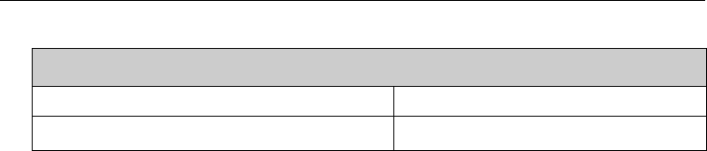
GPS
TTFF(cold start)initial positioning time
<1 min
TFF(hot start)initial positioning time
<10 seconds

DP990 DMR Two Way Radio User Manual
13 FCC STATEMENT
This device complies with Part 15 of the FCC Rules. Operation is subject to the following
two conditions:
(1) This device may not cause harmful interference, and
(2) this device must accept any interference received, including interference that may
cause undesired operation.
NOTE 1: This equipment has been tested and found to comply with the limits for a Class
B digital device, pursuant to part 15 of the FCC Rules. These limits are designed to
provide reasonable protection against harmful interference in a residential installation.
This equipment generates, uses and can radiate radio frequency energy and, if not
installed and used in accordance with the instructions, may cause harmful interference to
radio communications. However, there is no guarantee that interference will not occur in
a particular installation. If this equipment does cause harmful interference to radio or
television reception, which can be determined by turning the equipment off and on, the
user is encouraged to try to correct the interference by one or more of the following
measures:
- Reorient or relocate the receiving antenna.
- Increase the separation between the equipment and receiver.
-Connect the equipment into an outlet on a circuit different from that to which the
receiver is connected.

DP990 DMR Two Way Radio User Manual
-Consult the dealer or an experienced radio/TV technician for help.
NOTE 2: Any changes or modifications to this unit not expressly approved by the party
responsible for compliance could void the user's authority to operate the equipment.
Output power listed is rated conducted. This device must be restricted to work-related
operations only in an Occupational/Controlled RF exposure environment and must
operate with a duty factor not exceeding 50%. This transmitter may operate with the
antenna(s) documented in this filing in Push-to-Talk and body-worn configurations.
RF exposure compliance is limited to the specific belt-clip and accessory
configurations as documented in this filing and the separation distance between user
and the device or its antenna shall be at least 2.5 cm. All qualified end-users of this
device must have the knowledge to control their exposure conditions and/or duration
to comply with occupational/controlled Exposure limit and requirements. The highest
reported SAR values for Face-held, body-worn and simultaneous transmission
conditions are 2.77 W/Kg, 3.70 W/Kg and 3.74W/Kg respectively.
This device contains Bluetooth and Two Way Radio transmitters.