Kirisun Communication DR60001 DMR Repeater/Transceiver User Manual 1
Kirisun Communications Co., Ltd DMR Repeater/Transceiver 1
Contents
- 1. User Manual 1
- 2. User Manual 2
User Manual 1

DR600 , DR600-01
DR600 , DR600-01

Kirisun DR600,DR600-01 digital repeater manufactured
which always incorporates the
We believe Kirisun DR600,DR600-01 digital repeater,
DR600, DR600- 01
User Manual
Digital Repeater
We are very grateful for your purchasing
by Kirisun Communications Co., Ltd.
technology,
brings great convenience to your life and work and meets demands for reliable
communication.
latest

II
Notice
◆ Please carefully read this instruction manual before using the product for your easy operation.
We will consider that you have read this manual once you use the product.
◆ Please carefully keep this manual for future reference.
◆ In order to protect your legal rights from infringement, please carefully fill in the warranty card
and claim valid receipt.
◆Kirisun and its authorized partners own the intellectual property of all the parts of this product
(including accessories). Any design and materials may not be modified, copied, extracted or
translated without authorization of Kirisun or its authorized parities.
◆This product may involve update or modification in future, and Kirisun owns the right to change
the specifications of software and hardware described in this manual without further notice.
Specifications and information contained in this manual are for reference only.
◆ All the contents are carefully proofread, but mistakes may be inevitable. The rights of final
explanation are reserved by Kirisun.

III
Safety Precaution
◆The radio can only be repaired or maintained by professional technicians. The user must
not disassemble the radio at liberty.
◆The settings and installation shall be approved by local radio management department.
◆Lightning protection is required when installing the repeater antenna.
◆Please use qualified power supply, antenna, thunder preventer, feeder and other
accessories during installation, otherwise the repeater may be damaged.
IV
Contents
1
Unpacking and Checking ........................................................................................................... - 1 -
1.1
Accessories ........................................................................................................................ - 1 -
2
Overview .................................................................................................................................... - 3 -
2.1
Power Switch ...................................................................................................................... - 5 -
2.2
ACCY Interface................................................................................................................... - 5 -
2.3
Panel LED Indicator ........................................................................................................... - 8 -
3
Basic Operation .......................................................................................................................... - 9 -
3.1
Power on /off Repeater ...................................................................................................... - 9 -
3.2
Voice and Data Transmission ............................................................................................ - 9 -
3.3
IP Interface ....................................................................................................................... - 10 -
3.4
Emergency Alarm ............................................................................................................. - 10 -
3.5
Programming Software ..................................................................................................... - 10 -
3.6
IP Connect* ...................................................................................................................... - 16 -
4
Trouble shooting ...................................................................................................................... - 16 -
5
Parameters ............................................................................................................................... - 17 -

- 1 -
1 Unpacking and Checking
Please carefully open the box and make sure the items listed below are included. For items
missing or damaged during delivery, please contact the local dealers for help.
1.1 Accessories
Item Quantity
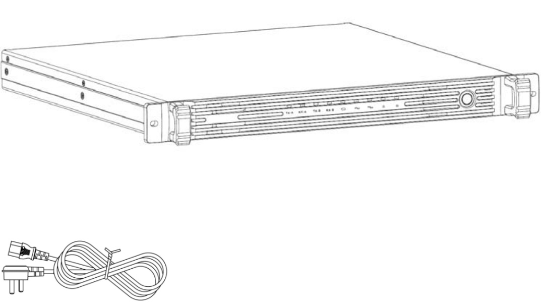
Repeater 1
Power Cable 1
User Manual 1
Certificate 1
- 2 -
Repeater:
Power Cable:
- 3 -
2 Overview

- 4 -
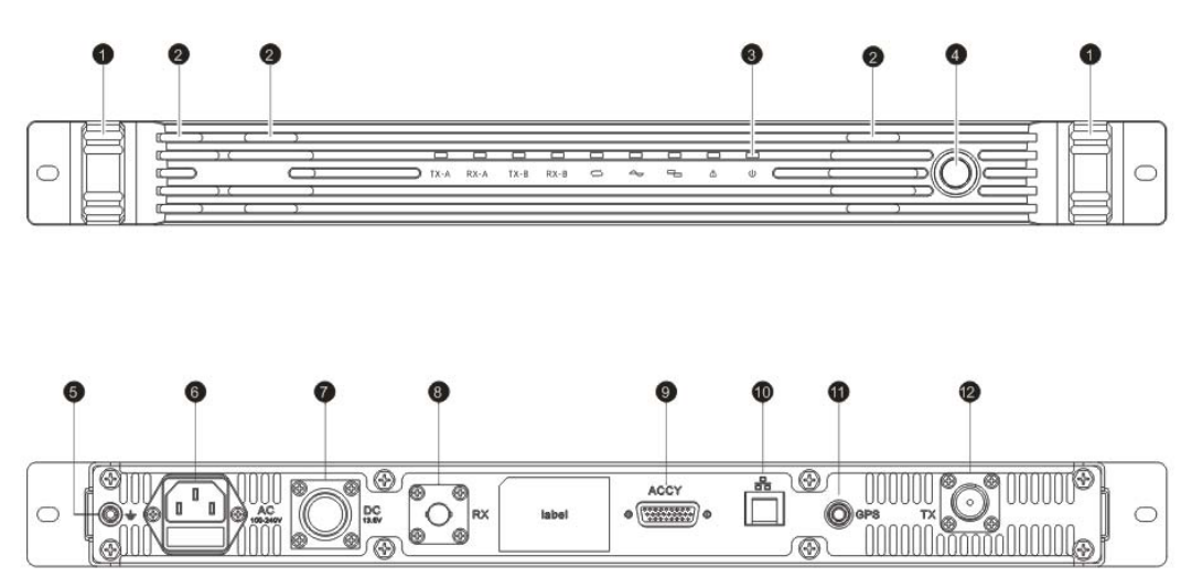
No. Part Name
1 Handle
2 Fan
3 Indicator
4 Power Switch
5 Ground Interface
6 100-240V AC Inteface
7 13.6V DC Interace
8 RX Signal Interface
9 ACCY Interface
10
Ethernet Interface
11 GPS Interface
12 TX Signal Inteface
- 5 -
2.1 Power Switch
Press this button to power on/off the repeater.
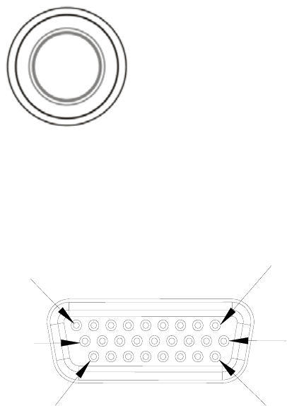
2.2 ACCY Interface
1
9
10
18
19
26

PIN1 DC 13.6V Output
- 6 -
2.2.1 PIN Description
Pin Description
PIN2 Ground Cable
PIN3 Null
PIN4 Null
PIN5 Null
PIN6 Null
PIN7 External PTT Signal input, High level active .when connected with Pin20,
enter transmission mode used for testing and bridge connection;
PIN8 SPEAKER-
PIN9 SPEAKER+
PIN10 ACC_MAP_ID2; used for testing
PIN11 ACC_MAP_ID1; used for testing
PIN12 Null
PIN13 RS232 serial port RXD
PIN14 RS232 serial port TXD
PIN15 Ground Cable

- 7 -
PIN16 Null
PIN17 Ground Cable
PIN18 External Analogue Audio Input
PIN19 Ground Cable
PIN20 High level electrical signal output
PIN21 Squelch is on when it is connected to PIN20 and it is used for testing
PIN22 Null
PIN23 Null
PIN24 PTT output; used for bridge connection
PIN25 Null
PIN26 Null
2.2.2 External Interface Description
• To Activate the External PTT
Connect PIN7 and PIN20 of ACCY interface to activate the external PTT, and you can test the TX signal
of repeater.
• Test the Analogue Receiving
Connect PIN10 and PIN20 of ACCY interface to test the analogue receiving.
• Reset IP Address
- 8 -
Connect PIN10 and PIN20 of ACCY interface. The repeater changes the IP address and gateway
address to the IP on the label, but the data of them are not changed. After re-boot, the configured IP
address and gateway address will be recovered.
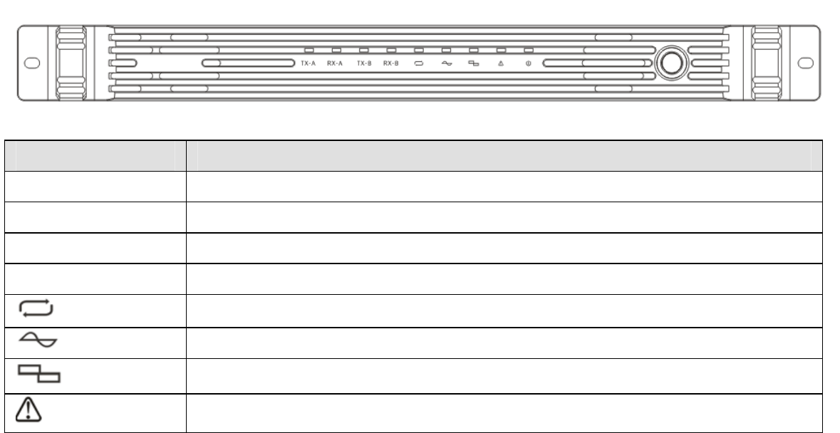
2.3 Panel LED Indicator
Indicator Description
TX-A Time Slot 1 TX Indicator
RX-A Time Slot 1 RX Indicator
TX-B Time Slot 2 TX Indicator
RX-B Time Slot 2 RX Indicator
Signal Transmission Indicator
Analogue Mode Indicator
Digital Mode Indicator
Emergency Indicator
- 9 -
Indicator Description
Power Indicator
3 Basic Operation
3.1 Power on /off Repeater
When the repeater is off, press the power switch to power it on. When the indicator glows,
the system starts to operate, and the indicator or will indicate the current work mode.
Press the power switch to power off the repeater when it is on.
3.2 Voice and Data Transmission
The TX frequency and RX frequency on the repeater channel are different. The signals received on the
current channel will be transmitted on the same channel, and in the meantime, the weak signals will be
switched to stronger signals before transmission to increase the communication distance. The
indicator glows when transmitting/receiving. The indicator flashes when analogue signal is
being received or transmitted and the indicator flashes when digital signal is being received or
transmitted. Parameters such as RX/TX frequency, CTCSS on the channels can be programmed by
- 10 -
dealers.
One analogue channel or digital/analogue adaptive channel can edit one group of CTCSS/CDCSS
codec list, and when CTCSS/CDCSS is received on this channel, the repeater will transmit the
correspondent CTCSS/CDCSS codec list.
3.3 IP Interface
Default IP address: 192.168.1.100. You can upgrade software, configure the programming parameters
and perform extended development through this interface.
3.4 Emergency Alarm
The emergency indicator glows during abnormal situations, for example, when RX frequency lost lock,
the emergency indicator flashes every one second and when TX frequency lost lock, two seconds.
When both TX and RX frequency lost lock, the indicator glows constantly. Please turn to professional
technician for help when abnormal situations happen.
3.5 Programming Software
Please check the network status before programming the repeater. First make sure the network button
on the tool bar is pressed(the IP address option will be greyed out if it is not pressed) and also make
sure the connection button is pressed. In case of the connection button is pressed, the programming
software will automatically connect to the matched repeater through IP according to the IP address; the
status bar will show ”XX network” after the connection is completed. If there is another programming
are available, or you can define fr
400-470MHz
- 11 -
software trying to connect to the same repeater, it shows busy network status on the second software,
meanwhile, the connection button will pop up automatically, and you need to click it for re-connection.
3.5.1 Menu
New: creates new channel information. The repeater creates new channel information configuration file
and one analogue channel by default with default parameters.
Open: open the file saved on the device.
Save: saves information configuration on the current channel.
If the channel information is newly created or read from the repeater, the save path should be selected
(similar to “Save as”) .
Save as: choose a path to save the configuration.
Exit: exits the programming software.
3.5.2 Radio Type
Radio Type: select repeater for radio type. Frequency 136-174MHz,
equency band yourself. The self-defined frequency band
should be within the available range.
3.5.3 Edit Menu
• General Settings
Equipment ID:the only identity on the device. It is used for recognition to multi-station networking and
base station.
- 12 -
Group Call Hang Time: during group call on the terminal, if no PTT button is pressed on any terminals,
the repeater will keep call hang time and does not accept signals of other group. If there is any one of
the members press PTT button during the call hang time, the hang time will be counted again. After the
call hang time is over, the call ends and the channel resources are released. Value range: 0~7000
milliseconds; step value: 500 milliseconds; 4000 milliseconds by default.
Private Call Hang Time: after a private call is initiated on the terminal, and if no PTT button is pressed
on both parties, the repeater will keep call hang time for the terminals. During the call hang time, the
repeater does not accept other calls. After the call hang time is over, the call ends and the channel
resources will be released. Value range: 0~7000 milliseconds; step value is 500 milliseconds; 4000
milliseconds by default.
Emergency Call Hang Time: after an emergency call is initiated, and if no PTT button is pressed on
both parties, the repeater will keep call hang time for the terminals. During the call hang time, the
repeater does not accept other calls. After the call hang time is over, the call ends and the channel
resources will be released. Value range: 0~7000 milliseconds; step value is 500 millisecond; 4000
milliseconds by default.
Call Hang Time: after the terminal call ends, the repeater keep call hang time for the terminal. During
this time, press PTT button without having to establish connection to continue the call. Value range:
0~7000 milliseconds; step value: 500 milliseconds; 4000 milliseconds by default.
- 13 -
• Internet Settings
Local IP:repeater IP address, such as 192.168.1.100.
Subnet Mask: the repeater subnet mask in local area network, such as 255.255.255.0.
Gateway: the repeater gateway in the local area network, such as 192.168.1.1.
DNS:configure the domain name server or set it as 0.0.0.0.
Networking Modes: supports three modes including: no network, as server or as slave device. When it is
used as server, the local monitor port should be configured and the slave device is connected to system
network through this port. When it is used as slave device, the serve IP(or domain name) and port
should be configured.
Network Time Slot Configuration: both two time slots can be equipped with or without network. In case of
network status, the internet time slot ID should be configured. When the repeater is networked, it will
determine whether it should transmit data according to network time slot ID. It transmits data when the
ID is different while it does not transmit data if the ID is different.
Indicator Setting: in the networked status, the repeater will transmit signals regularly according to
indicator settings, so that the portable radios can perform roaming according to signals. The time interval
to activate the repeater is ranged from 10 seconds to 600 seconds; 30 seconds by default. The continual
time to activate the repeater is ranged from 200 milliseconds to 7000 milliseconds, 1000 milliseconds by
default.
Encryption Setting: encryption is optional. The password is set to be 10 hexadecimal characters, such as:
8A4428331D.
- 14 -
Message Delay Setting: the delay setting is used to prevent network latency. The user can set the delay
time based on the network status. Value range: 60 milliseconds to 960 milliseconds; step value is 60
milliseconds.
• Temperature Control
Fan Control Mode: the fan can be turned on constantly or turned on automatically according to power
amplification temperature.
Power Amplification Protection Temperature: when the power amplification temperature exceeds
the specified threshold, the power amplifier will be disabled automatically. 85℃ by default.
Fan Enable Threshold Temperature: when the temperature is higher than the specified threshold, the
fan will be turned on automatically. 40℃ by default.
Fan Disable Threshold Temperature: when the temperature is lower than the specified threshold, the fan
will be turned off automatically. 30℃ by default.
Standing Wave Ratio: used to test whether the antenna is well matched with transmitter. Default value:
3.0.
• Channel Settings
Band Width: select channel spacing for current channel. Options: 12.5kHz、
25 kHz. Default
value: 12.5 kHz.
Color Code: select color code for current channel. Only radios with same frequency and color code can
communicate with each other. Value range: 0~15. Default value: 1.
Squelch Type: select RX mode for current channel. Options: CSQ, CTCSS, CDCSS, -CDCSS. Default
value: CSQ.
Squelch Level: set the squelch electrical level.
25kHz not for FCC used.
- 15 -
CTCSS Frequency: when the CTCSS squelch mode is selected, you need to select one CTCSS
frequency value, otherwise the call between two parties is not possible. Value range: 0~254.1Hz; step
value is 0.1 Hz; default value: 67 Hz.
CDCSS: if the squelch type is CDCSS or –CDCSS, you have to select one CDCSS value, otherwise the
call between two parties is impossible. Value range: 0~777; step value: 1; default value: 023.
Notice:
(1)The squelch level is only applied to analogue channel.
(2) The carrier cannot be selected for mixed channel receiving. It must choose CTCSS, CDCSS or
–CDCSS.
3.5.4 Programming Menu
Read: read data from repeater.
There will be a progress bar indicating progress during the reading process, and you can set to
automatically exit the data window when the data is fully read.
Write: write the configured data into repeater.
There will be a progress bar indicating progress during the writing process, and you can set to
automatically exit the data window when the data is fully written.
Notice:
(1) Check the network status before reading data and make sure that internet option is ticked. The IP
on the software tool bar should be same as the repeater IP.
(2) When the connection is completed, it shows “internet OK” on the status bar, or it shows “internet
- 16 -
XX”.
Upgrade: you can download each function module from PC to repeater and configure with main
parameters.
Select the path for upgrade package before upgrade.
3.6 IP Connect*
An IP connected system can be composed of multiple repeaters through network. This system includes
one master device and multiple slave devices (32 members max.). The master device records and
maintains all the device information for repeater, and when certain slave device joins in or leaves, the
master device will inform other devices. If the master device goes faulty and is not able to maintain, other
devices maintain the same working status.
In the same IP connected network, when one repeater receives signal from certain portable, it will
transmit the signal to the rest of the members. As long as the ID of wide area network is the same, it can
transmit without limitation to time slot and frequency.
In case of feature conflict, the IP connected system will make adjustable assignment so as to arrange
the same features being processed in the same system at the same time.
Note: features marked with “*” is option and please contact your dealer if you need it.
4 Trouble shooting
A. Programming Software Connection Failure
Wrong repeater IP entered on the programming software or the user forgets repeater IP.
400-470MHz
- 17 -
B. Transmission Failure
Check if the frequency configuration between the portable and repeater is the same and whether their
modes are matched.
5 Parameters
Frequency Range: 136-174MHz, ,
AC: 100-240V@2.5A 50/60 Hz
DC : 10.8-15.6V@15A
DC Insurance: 13.6V15A
AC Insurance: 2.5A 250VAC, 5x20mm
Insurance Type: HRC ceramic, Time lag (T)
Supplied Power: 200W
TX Power: 40W(UHF) / 45W(VHF)
Size: 482.6mm(Length)*450mm(Width)*44mm(Height)
1.5dBi (VHF), 0dBi(UHF)
100 cm away from your body, in
Installation de l'antenne: Installez l'antenne portable au moins 100 cm de votre
FCC & ISED Statement
a at least
:2005; Canada
strength limits of RSS requirement
adhere to the following procedures:
The device complies with RF field
only. In terms of measuring
and is authorized by the FCC for occupational use
or controlled RF exposure environment
th the FCC RF exposure limits for occupational
Antenna Installation: Install the mobile antenn
RFEnergyExposureCompliance
ƽ Your radio is designed and tested to comply with a number of national and international
standards and guidelines (listed below) regarding human exposure to radio frequency
electromagnetic energy. This radio complies wi
RF energy for compliance with the FCC exposure guidelines, your radio radiates measurable
RF energy only while it is transmitting (during talking), not when it is receiving (listening) or
in standby mode.
ƽ
Your radio complies with the following of RF energy exposure
standards and guidelines
ƽ United States Federal Communications Commission, Code of Federal Regulations; 47CFR
part 2 sub-part J
ƽ American National Standards Institute (ANSI)/Institute of Electrical and Electronic Engineers
(IEEE) C95. 1
ƽ Institute of Electrical and Electronic Engineers (IEEE) C95. 1-2005 Edition
ƽ International Commission on Non-Ionizing Radiation Protection (ICNIRP) 1998
ƽ To ensure optimal performance and compliance with the occupational/controlled environment
RF energy exposure limits in the above standards and guidelines, users should transmit no
ƽ Gain of antenna must not exceed
ƽ
accordance with the requirements of the antenna manufacturer/supplier.
ƽ
respecter les
Pour assurer une performance optimale et le respect du travail / contrôlée
limites d'exposition à l'environnement de l'énergie RF dans les normes et les
lignes directrices ci-dessus, les utilisateurs
procédures suivantes:
corps, conformément
avec les prescriptions du fabricant de l'antenne / fournisseur.
ƽ
ƽ
ƽ
RSS-119 Issue 12, MAY 2015; RSS-247 Issue 1 May 2015
Gain de l'antenne ne doit pas dépasser 1.5 dBi(VHF),0dBi(UHF)
Operation is subject to the following two conditions: 1. This device may not cause harmful
interference, and 2. This device must accept any interference received, including
interference that may cause undesired operation.
Note:” Changes or modifications to this unit not expressly approved by the party
responsible for compliance could void the user’s authority to operate the equipment.”
This device complies with Industry Canada licence-exempt RSS standard (s).
Operation is subject to the following two conditions: (1) this device may not cause
interference, and (2) this device must accept any interference,including interference
that may cause undesired operation of the device.
Le présent appareil est conforme aux CNR d'Industrie Canada applicables aux
appareils radio exempts de licence.
L'exploitation est autorisée aux deux conditions suivantes:
(1) l'appareil ne doit pas produire de brouillage, et
(2) l'utilisateur de l'appareil doit accepter tout brouillage radioélectrique subi, même
si le brouillage est susceptible d'en compromettre le fonctionnement.

- 18 -