Kirisun Communication PT420801 Two-way Radio User Manual
Kirisun Communications Co., Ltd Two-way Radio Users Manual
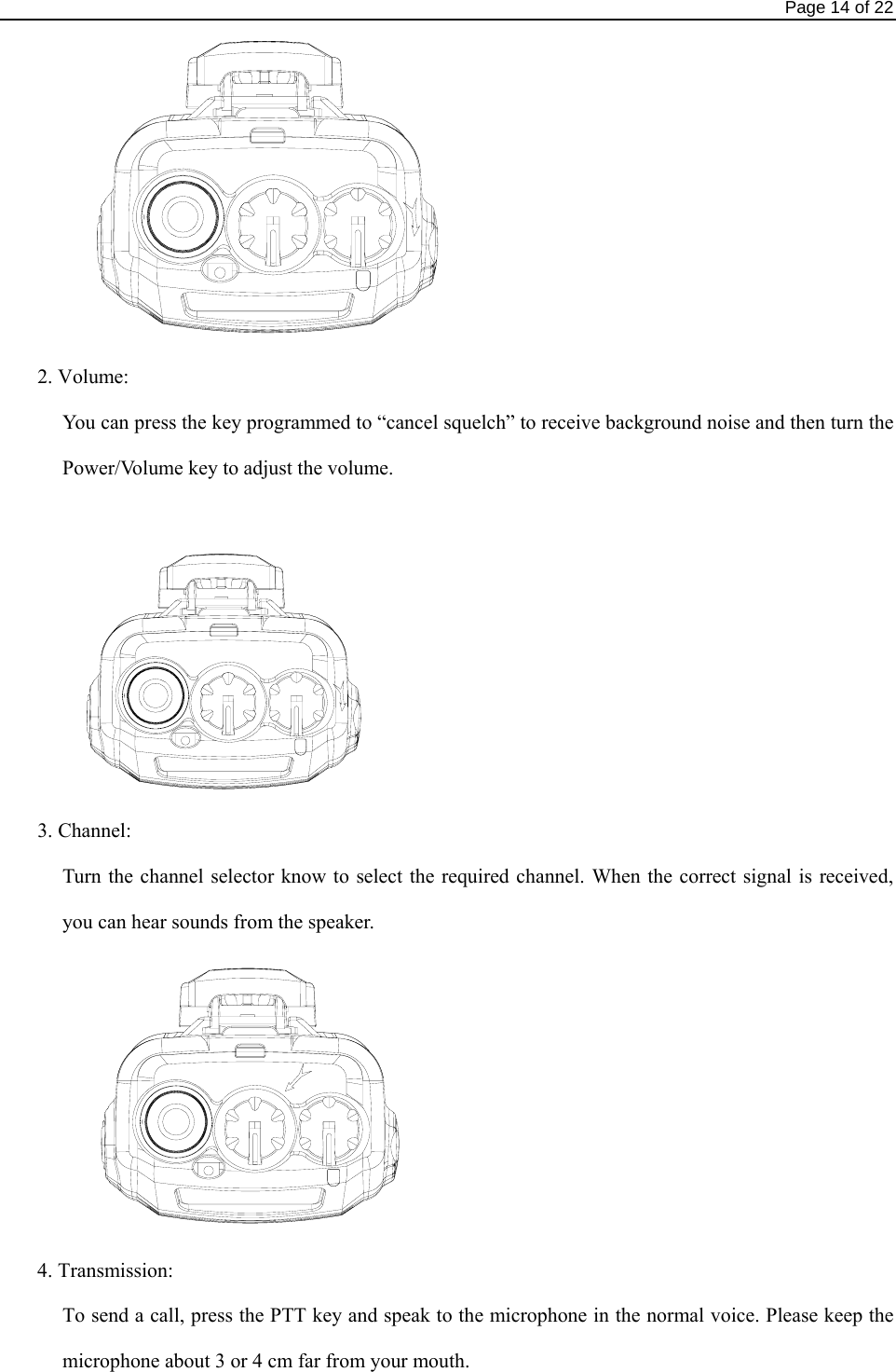
UserManual.wiki
>
Kirisun Communication
>
PT420801 User Manual
User Manual
Navigation menu
Upload a User Manual
Namespaces
Wiki Guide
HTML
PDF
Info
Views
User Manual
Discussion / Help
Navigation


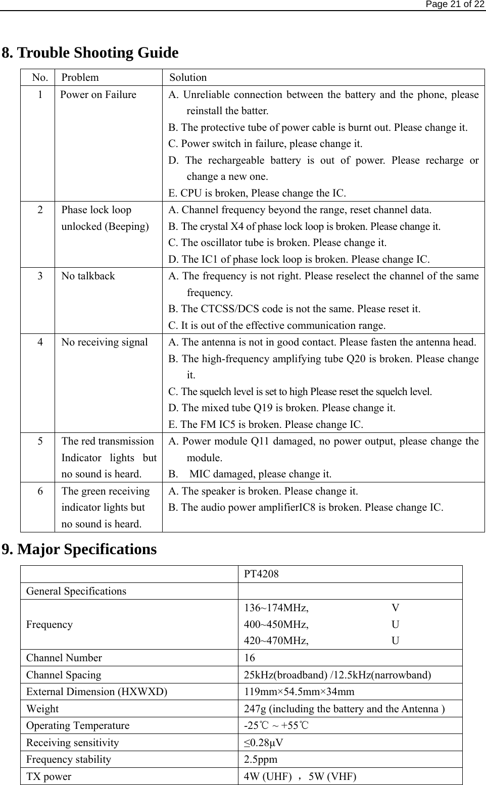
![Page 20 of 22 6.10 Lone worker If Lone worker is set to be enabled, press the key “Lone worker” to enable the Lone Worker Mode. Start the Lone worker timer and when the preset Lone worker time is reached, the station will alarm, after the alarm time, the station will enter the Emergency Alarm Mode and give out the Emergency Alarm. In the Lone worker Mode, press the “Lone worker” key again to quit the Lone worker mode. In the Lone worker Mode, press the key programmed for “Lone worker reset” (the specific key to select lone worker reset mode) or any key (any key to select lone worker reset mode), the Lone worker timer will start timing again. 6.11 Emergency Alarm Press the key programmed for “Emergency Alarm” (the time of pressing must be longer than the de-bounce time of the emergency alarm switch) to enter the Emergency Alarm mode. “E” will be displayed. You can set alarm tone according to the programming software or send your own ID or background tone to your friend or the system. In the Emergency Alarm Mode, press the key “Emergency Alarm Off” to quit the Emergency Alarm Mode and disable the alarm tone or stop sending it and resume normal operation. 7. Wired Clone Mode If the wired clone function is enabled, the radio will not quit after entering the wired clone mode. To return to normal user mode, the user needs to restart the machine. The operating steps go as follows: 1. Press [P1] keys for power-on until show “C” and enter the clone mode. If the function is disabled, it will enter the user mode. 2. Connect the slave radio with the wired clone cable first, and then turn on. 3. Press key [P2] on the master radio for starting clone. During transmitting the data, the master radio lightens red, and the slave radio lightens green and indicates “P”. After the slave radio receiving all the data, the red light on the master radio is off, and the slave radio restarts. 4. You can keep copying according to step 3 above. Note: The master displays success and the slave automatically restart upon successfully receipt of all data.](https://usermanual.wiki/Kirisun-Communication/PT420801/User-Guide-1092095-Page-20.png)