Kirisun Communication PT650001A Two-way Radio User Manual
Kirisun Communications Co., Ltd Two-way Radio
User Manual

PT6500 User’s Manual
Page 1 of 26
PT6500 User’s Manual
CONTENTS
■ Unpacking and checking
◆ Supplied accessories
■ Preparation
◆ Charging the battery
◆ Installing/Removing the battery pack
◆ Installing the antenna
◆ Installing the optional speaker/microphone
◆ Installing the belt clip
■ Getting acquainted
■ Basic Operation
■ Programmable Button functions
■ VOX
■ Copy mode
■ Whole setting
◆ Time-out Timer(TOT)
◆ Battery Saving
◆ Low battery warning
◆ Voice Annunciation of Channel Number
◆ CTCSS/ DCS
■ User’s resolution
◆ Busy Channel Lockout(BCL)
◆ Receiving squelch mode
◆ DTMF signaling
◆ 2TONE signaling
◆ Transmit start/over signaling (PTT ID)
■ Problems and troubleshooting
■ Major Specifications
■ Status setting
PT6500 User’s Manual
Page 2 of 26
█ Unpacking and checking
Unpack the transceiver carefully. We recommend that you identify the items listed in the following table
before discarding the packing material. If any items are missing or have been damaged during
shipment, please contact the dealer immediately.
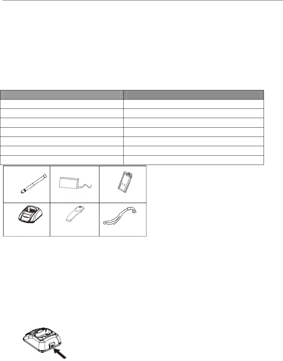
Supplied accessories
Item Quantity
Antenna 1
Battery 1
Belt clip 1
Charger 1
Power adapter 1
Hand strap 1
User’s Manual 1
█Preparation
◆Charging the battery
Connect the power adapter with the battery charger. Plug the adapter into an AC wall outlet
and the indicator turns green.
Place the battery or transceiver into the charger slot, and make sure the transceiver has
been turned off.
Make sure the battery is well connected with charger, then the indicator turns red or flashes,
then the charger gets in the state of charging automatically.
A
ntenna
P
ower a
d
a
p
te
r
B
atter
y
Ch
ar
g
e
r
B
e
l
t c
lip
H
an
d
stra
p

PT6500 User’s Manual
Page 3 of 26
When battery is fully charged the indicator turns green.
The performance will be at the best condition if you remove the battery when the green
indicator is on. Then remove the power adaptor from the wall outlet.
The charger will enter the protection mode when the yellow indicator flashes, which means
the temperature or the circuit is abnormal. Do not charge the battery at this moment, just
remove the battery and turn off the power of the charger.
Notes:
* The battery is not fully charged in the factory. Before the initial use, please charge the new
battery.
KB-36C Li-ion battery of this company is adaptable with this machine.
* When you charge the battery the first time or after long time storage (2 months), several
times of charging is needed. Make sure the battery is charged at least once every three
months.
* Do not charge the battery again if it is charged fully or not in the low-pressure warning
mode, otherwise, its life will be shortened or it will be damaged. Remove the battery from
the charger after charging.
* There is a protection circuit in KB-36C battery, so the power will be cut off at too low
battery.
PT6500 User’s Manual
Page 4 of 26
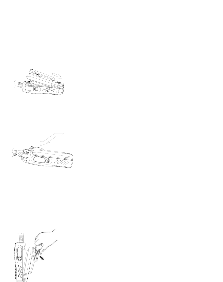
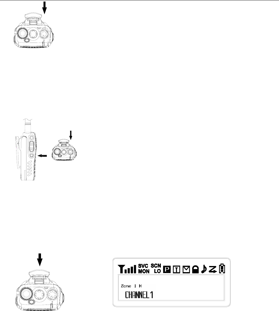
◆Installing/Removing the battery pack
To install the battery pack:
Match the 3 bulges of the battery pack with the corresponding holes at the rear Button of
the transceiver.
To install the battery pack:
Then firmly press the battery pack downwards to lock it in place until a click is heard.
To remove the battery pack:
Use your thumb to press the belt clip, and one side of your index finger to press the release
button; and then pull the battery away from the transceiver.
Notes:
* Do not cause short-circuit or throw the battery to the fire.
* Do not disassemble the battery by your self.
PT6500 User’s Manual
Page 5 of 26
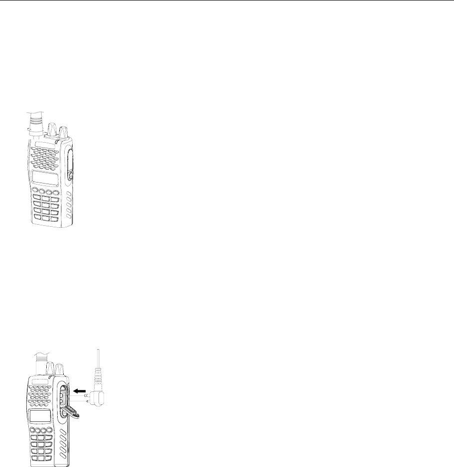
◆Installing the antenna
Screw the antenna into the connector at the top of the transceiver by holding the Button of
the antenna and turn it clockwise until secure.
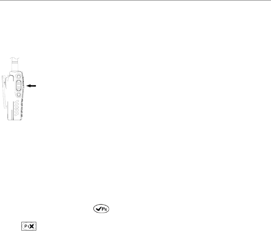
◆ Installing the optional speaker/microphone
Insert the speaker/microphone plug into the jacks of the versatile connector, and fix it with
the supplied snail screw.
7
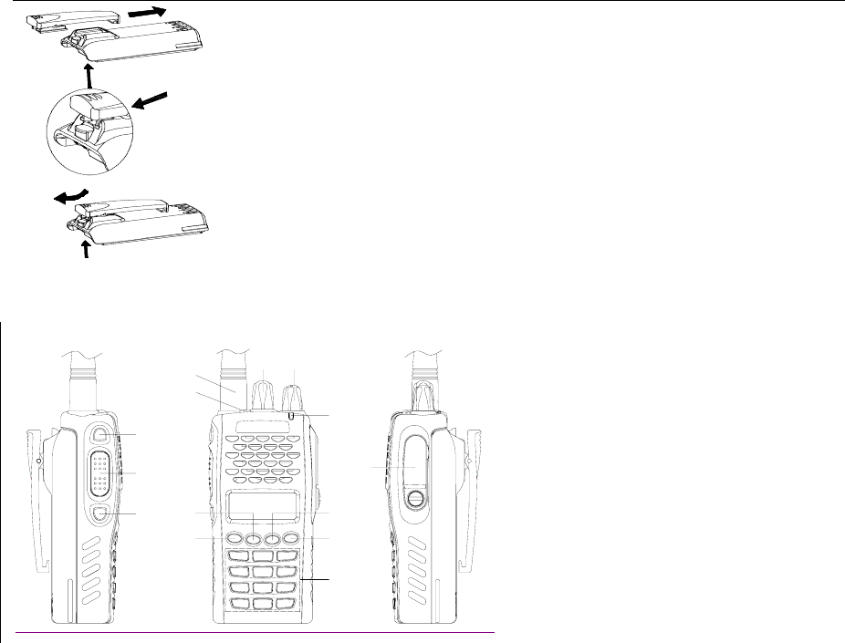
◆ Installing the belt clip
Match the grooves of the belt clip with those on the rear of the battery. Then press the
support belt clip downwards to lock it in place. Push the card by inserting your nail or tool
into the groove at the upper part of the clip to remove the belt clip.
PT6500 User’s Manual
Page 6 of 26
Getting acquainted
D
E
A
CB
G
H
F
N
J
IL
K
M
The functions of the components are as follows:
A. LED Indicator
Lights red while transmitting;
Lights green while receiving a signal.
B. Power/Volume Switch
Turn clockwise till a click is heard to switch on the radio.
Turn counterclockwise till a click is heard to switch off the radio.
Rotate to adjust the volume after turning on the radio.
C. Channel Selector
Rotate to select the channel 1-128.
D. Antenna
E. Top Button (programmable button)
It is recommended to be set as the emergency warning Button.
F. Side button 1 (programmable button)
G. PTT(PUSH-TO-TALK):
To make a call, press and hold the PTT button, then speak into the microphone with
PT6500 User’s Manual
Page 7 of 26
normal voice.
H. Side button 2 (programmable button)
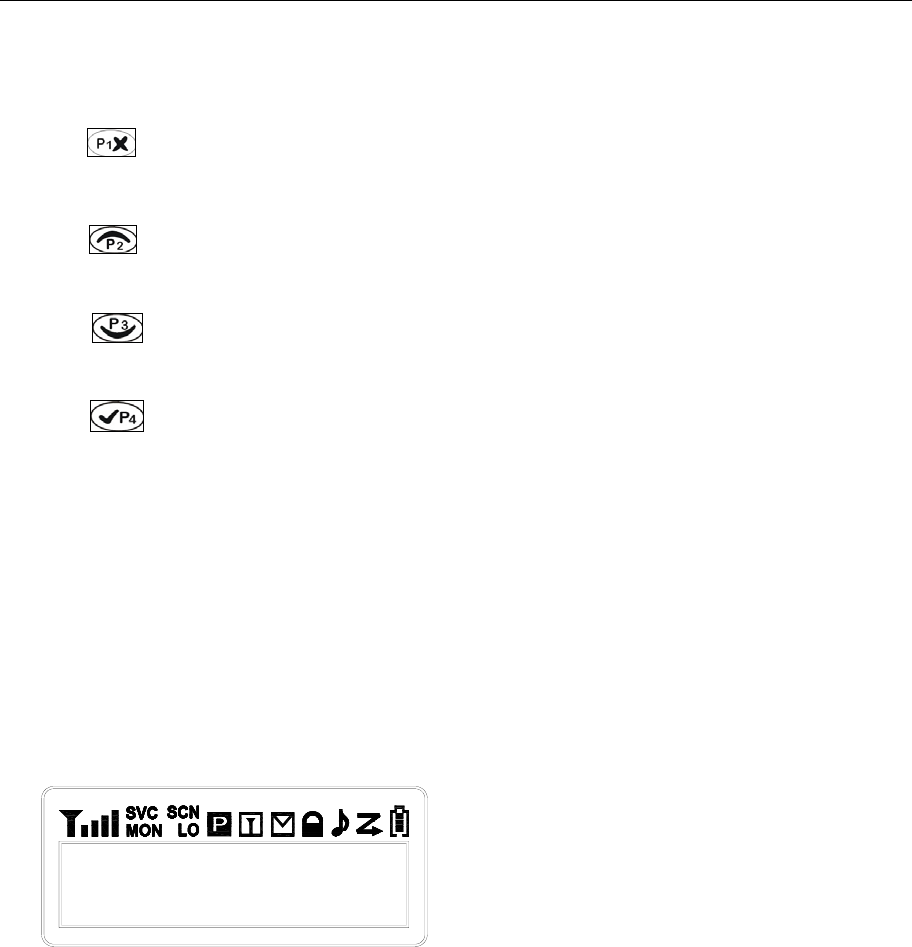
I. Button
Return and delete button in the menu.
J. Button
Select Button.
K. Button
Select Button.
L. Button
Enter and Confirm Button.
M. Numeric keypad
N. Microphone/speaker jacks
For connecting microphone/speaker.
Explanation for the screen
Basic Operation
1. Switch On
Switch on the radio by turning the Power/Volume switch clockwise
till a click is heard, then the radio will be in the state of stand by
and you will hear a beep if the dealer has set it.
PT6500 User’s Manual
Page 8 of 26
2. Adjust Volume
Press the button preset as canceling squelch to listen to the background noise and rotate
the Power/Volume switch to adjust volume.
3. Select a Channel
Rotate the channel selector to select channels. You will hear voice from the speaker while
receiving proper signals.
As shown in the above right figure:
Zone 1 is the zone of current channel (8 zones from 0 to 7).
H is the transmit power of the channel, H stands for high power,
CHANNEL 1 is the current channel (128 zones from 1 to 128).
PT6500 User’s Manual
Page 9 of 26
4. Make a Call
To make a call, press PTT, and speak in normal voice and please keep your mouth 3~4
cm away from the microphone.
5. Receive a Call
Release the PTT button to receive a call.
Your dealer can set CTCSS, DCS, 2 Tone signaling on you radio channels by PC software.
If you select a channel that has been preset with the tone signaling, you will not hear any
other calls except those from your own system.
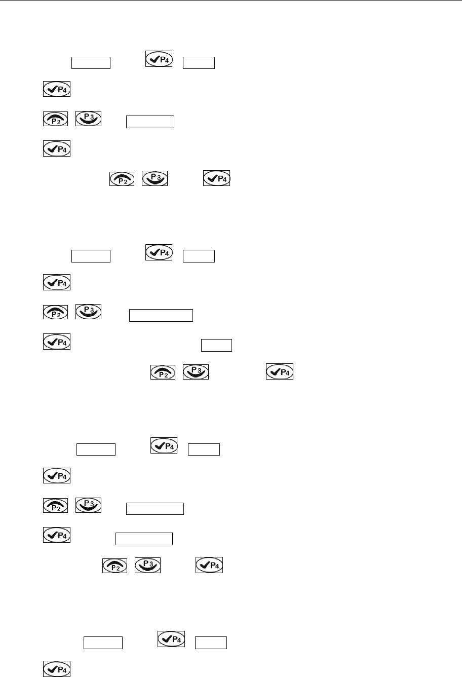
6. Operation on menu: press “ ”button to enter the menu or confirm any contents;
press “ ” button to return to the previous menu or cancel the set. When entered the
menu, select the sub-menu with the “channel selector”, “ “or “ ”.
The menu is as follows:
O
pen
/
c
l
ose
O
pen
/
c
l
ose
O
pen
/
c
l
ose
O
pen
/
c
l
ose
L
eve
l
0
-
9
Hi
g
h
, m
iddl
e,
low
M
e
n
u
S
e
l
ect s
q
ue
l
c
h
mo
d
e
N
um
b
er
li
st
S
e
l
ect zone
PT6500 User’s Manual
Page 10 of 26
If can not enter that way, you have to set in PC communications;
Set back light:
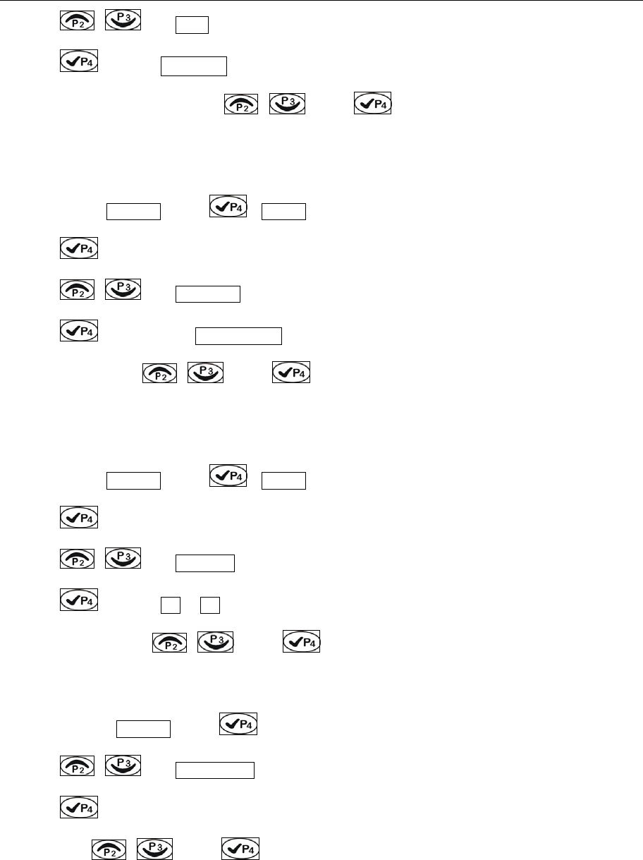
1. As shown: in CH 1 , press , utilities is shown.
2. Press to enter select mode,
3. Press / , and Back Light is shown,
4. Press to select On or Off,
5. Select On or Off with / , press to confirm.
Set the squelch level:
1. As shown: in CH 1 , press , utilities is shown.
2. Press to enter select mode,
3. Press / , then Squelch Level is shown,
4. Press to select squelch level, e.g., Leve 0
5. Change the squelch level with / , then press to confirm.
Set Companding:
1.As shown: in CH 1 , press , utilities is shown.
2. Press to enter select mode,
3. Press / , and Companding is shown,
4. Press to select Companding,
5. Select On or Off by / , press to confirm.
Set saving:
1.As shown: in CH 1 , press , utilities is shown.
2. Press to enter select mode,
PT6500 User’s Manual
Page 11 of 26
3. Press / , and Save is shown,
4. Press to select Save 1:4,
5. Chang the save percentage with / , press to confirm.
Set scrambler:
1.As shown: in CH 1 , press , utilities is shown.
2. Press to enter select mode,
3. Press / , and Scrambler is shown,
4. Press to select, e.g., Scrambler Off,
5. Select On or Off by / , press to confirm.
Set key tone:
1.As shown: in CH 1 , press , utilities is shown.
2. Press to enter select mode,
3. Press / , and Key Tone is shown,
4. Press to select Off or On,
5. Select On or Off with / , press to confirm.
Set speak On mode:
1.As shown: in CH 1 , press to enter select mode,
2. Press / , and Speak Mode is shown,
3. Press to select the speak on mode,
4. Select with / , press to confirm.
Set call list:

PT6500 User’s Manual
Page 12 of 26
1.As shown: in CH 1 , press to enter select mode,
2. Press / , and Call is shown,
3. Press to select the call list,
4. Select with / , press PTT to transmit.
■Programmable Button functions
The dealer can program the 2 Side Buttons and 1 top Button with one of the following auxiliary
functions.
None
Off (“do not set the functions”)
Scan
Separate working
Contact list
Show or hide the channel alias
Busy Channel Lockout (BCL)
Key lock
Squelch level selector
Companding
Scrambler
Battery power
Zone
Monitoring
Cancel Squelch
Emergency Alert
Back light
Rptr/Talkarnd
Express select channel 1
Express select channel 2
Call 1, 2, 3 or 4
Channel lock
Adjust display contrast

PT6500 User’s Manual
Page 13 of 26
Notes: programmable key can be set as short key or long key.
The following functions can be programmed by the dealer:
● None
Set of None。
● Scan
Press the button set as Scan to start scanning. While in scanning, the radio checks every channel (any
channel in any zone) and stops on the channel on which a signal is detected until that signal disappears.
If the delay time between signal disappearing and continuing scanning has been preset, the radio will
remain on that channel. Only when there are two channels added in the scan list and the scan function
has been activated, the radio can start scanning.
▲ It can be set as: short key: scan, long key:off.
1. Press the programmable key once to start scanning (it should be effective in the channel scan list).
2. Press once to quit.
Notes: there are 8 zones from 0 (default zone) to 7; and there can be 128 channels to the most in
each zone. There are totally 16 scan lists; you can select any scan list. Every scan list can scan
any channels in different channels (16 channels to the most).
● Separate working
Press the button set as Separate Working to start separate working. This mode is to ensure the safety
of the user while using the transceiver separately.
▲It can be set as: short key: personal working, long key:off.
1. Press the programmable key once to start personal working;
2. Press once again to quit.
Notes: the separate working is connected with the automotive checking in the programming
software, and will be effective when both are set.
● Contact list
Enter the Contact list quickly:
▲ It can be set as: short key: contact list, long key:off.
1. Press the programmable key once to enter the contact list Call
PT6500 User’s Manual
Page 14 of 26
2. Press again to enter the content interface of the contact list, e.g.: Dtmf Call
3. Select the options in the contact list with /
4. Press PTT to transmit
5. Press to quit.
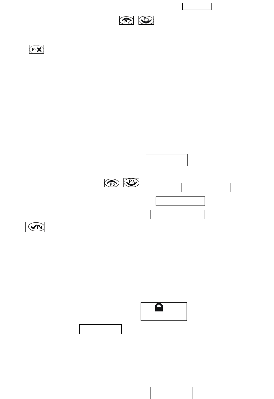
●Busy Channel Lockout (BCL)
Busy Channel Lockout can prevent you from interfering other radios that using the same channel.
Press the PTT button when the channel is busy, the radio with BCL function active will make warning
sound and prohibit transmitting. To stop the warning sound, please release the PTT button and the radio
returns to receiving mode.
▲It can be set as: short key: Busy Channel Lockout, long key:off.
1. Press the programmable key once, will be shown,
2. Select the character you need with / , e.g.:
3、Press to confirm.
●Key lock
Press the key programmed as “key lock” for one second to lock/unlock the keys for the transceiver.
▲ It can be set as: short key: key lock, long key:off.
1. Press the programmable key once, will be shown,
2. Press it again, will be shown.
●Squelch level Selector
Enter the “Select squelch level” instantaneously, 0~9 levels are available with the channel selector.
▲ It can be set as: short key: Select squelch level, long key:off.
1. Press the programmable key once,
will be shown,
BCL none
BCL none
BCL carry?
BCL carryPL?
CHANNEL
CHANNEL
Level 2
PT6500 User’s Manual
Page 15 of 26
2. Select squelch level with / , e.g.:
3. Press to confirm.
●Companding
Enter the Companding mode when press the key programmed as “Companding”,
▲ It can be set as: short key: Companding, long key:off.
1. Press the programmable key once to open the Companding mode,
will be shown,
2. Cancel the mode by pressing it again, will be shown.
●Scrambler
Press the key programmed as “scrambler” to prevent any third party to hear you talking on the phone.
▲ It can be set as: short key: scrambler, long key:off.
1. Press the programmable key once to open the scrambler mode,
will be shown,
2. Cancel the mode by pressing it again,
will be shown.
●Battery volume checking
Display the battery power.
▲It can be set as: short key: battery power checking, long key:off.
Level 3
Level 4
Level 5
Zone
CHANNEL 1
Zone
CHANNEL 1
CHANNEL 1
CHANNEL 1

PT6500 User’s Manual
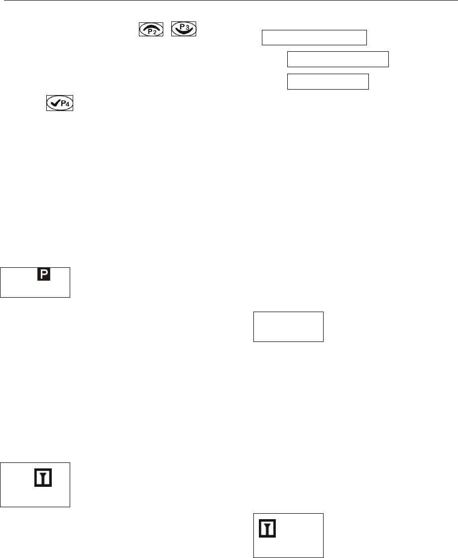
Page 16 of 26
1. Press the programmable key once: the battery power will be shown,
2. Press again: close the display.
● Monitoring
Press the programmed as “monitor trigger” to shut up the CTCSS、DCS、2Tone and DTMF signal, and
you can listen to the signals can not be heard in normal operation, press the key again to return to
normal operation.
▲It can be set as: short key: monitor, long key:off.
1. Press the programmable key once to start monitoring, Moni Moment ON
will be shown,
2. Press again: stop monitoring, Moni Moment OFF will be shown.
●Cancel squelch
Press the key, no matter what the signal or carrier wave is (including optional signal), squelch will be
cancelled.
▲It can be set as: short key: cancel squelch, long key:off.
1. Press the programmable key once to start squelch constantly,
2. If you do not press it, the squelch will still work.
●Emergency Alert
If press the top key programmed as “Emergency Alert”, you can set the warning ring according to the
programming software, or send your identity or background music to your companion or the system.
▲It can be set as: short key: emergency alert, long key:off.
1. Press the programmable key once to start alert,
2. Press it again to stop the alert.
●Back light
Turn on/off the back light.
▲It can be set as: short key: back light, long key:off.
1. Press and hold this key, the back light is on,
2. Release it to recover the normal mode.
PT6500 User’s Manual
Page 17 of 26
●Rptr/Talkarnd
When press the key programmed as “Rptr/Talkarnd”, the next transmission will be at the same
frequency as at which it is received.
▲It can be set as: short key: Rptr/Talkarnd, long key:off.
1. Press the key once, Rptr/Talkarnd will be shown,
2. Press to enter,
3. Press / to select the character you need: e.g.: Repeater Mode or Talkarnd mode,
4. Press to confirm.
●Instantaneously select the channel
Shift to the channel you selected instantaneously, so that you can communicate at the channel you are
used to.
▲It can be set as: short key: instantaneously select channel 1, long key:off.
1. Press the key once to instantaneously select the channel, e.g.:CHANN 15
2. Press again to return.
●Call 1, 2, 3, or 4
Press the side button programmed as Call 1, 2, 3, or 4 to transmit the specified code stored in the
contact list. Release “Call” button, and speak to the microphone to call with the PTT button still
pressed.
▲It can be set as: short key: Call 1, long key:off.
1. Press the key once to make a call(within the current channel), and will quit automatically after the
call.
●Voice Annunciation of Channel Number
Select or delete the voice annunciation function.
●Adjust display contrast
You can adjust the display contrast as per your need.
▲It can be set as: short key: display contrast, long key:off.
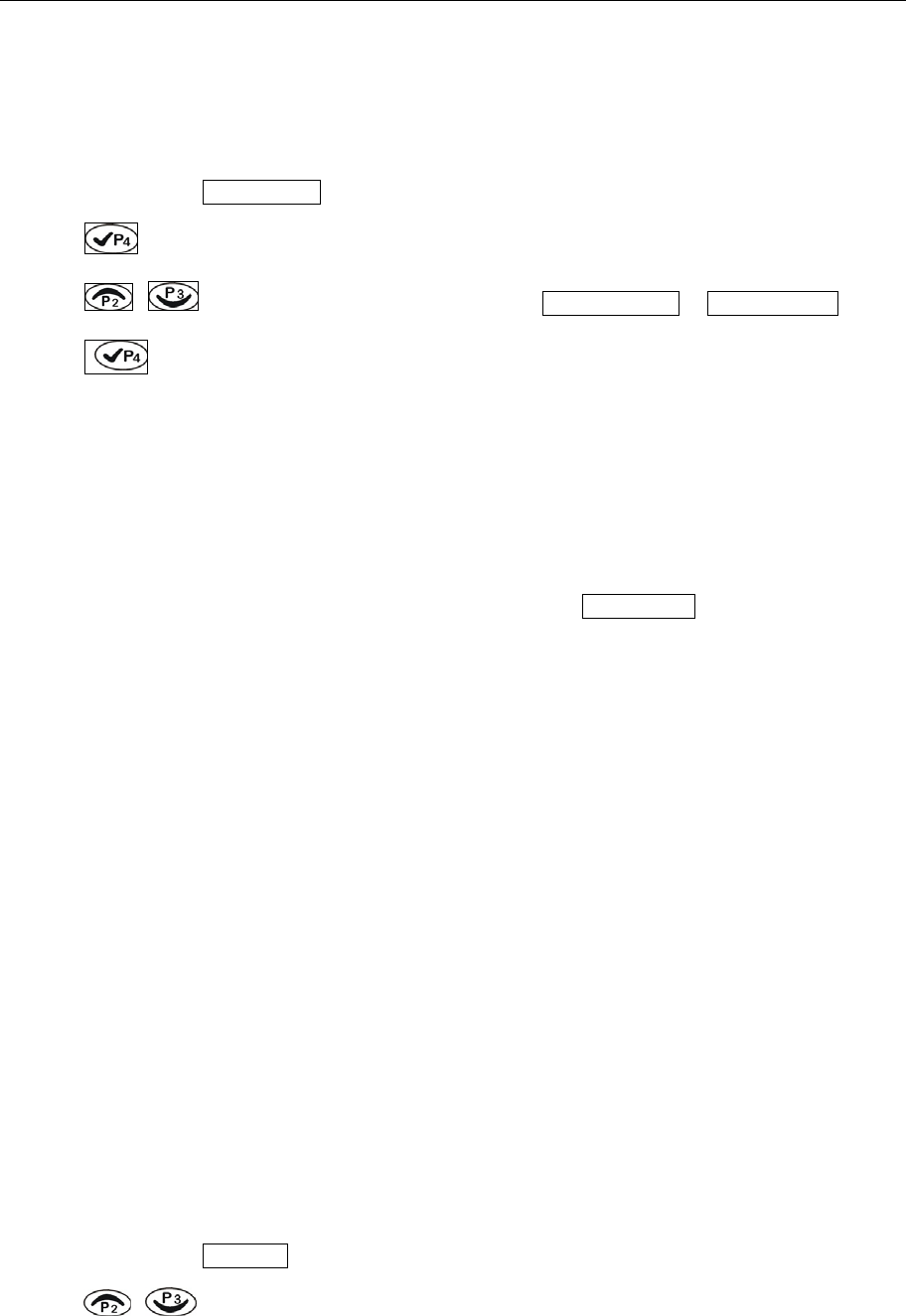
1. Press the key once, Contrast will be shown,
2. Press / to select the character you need,
PT6500 User’s Manual
Page 18 of 26
3. Press to confirm.
●Manual programming
The dealer can open the manual programming rights of:
Channel frequency set, CTCSS,DCS.
Basic operations of programmable keys:
You can set the programmable keys with the “key set” in PC software, as follows:
▲It can be set as: short key: display channel frequency, channel alias and channel No., long key:off.
1. Press the key once, display the channel alias, e.g.:
,
2. Press it again, the channel frequency will be shown, e.g.:
3. Press it a third time,the channel alias will be shown, e.g.:
▲It can be set as: short key: Zone, long key:off.
1. Press the key once, Zone No will be shown,
2. Select zone No. with / ,
3. Press to confirm.
▲It can be set as: short key: channel lock, long key:off.
1. Press the key once to perform channel lock, then you can not choose the
channel, will be shown.
2. Press it again to cancel channel lock, will be shown.
■ VOX
VOX function enables you to use the radio without manual operations. This function can only be set by
the dealer, and you have to be equipped with the specified earphones.
Before using VOX, you must set VOX gain level. Such setting enables the radio to identify the voice
volume. If the microphone is too sensitive, the background noise will trigger the radio to transmit. If the
microphone is not sensitive enough, it cannot receive your voice when you speak. Make sure to adjust
CHANNEL 1
401.66500
CH 1
CHANNEL 1
CHANNEL 1

PT6500 User’s Manual
Page 19 of 26
VOX gain level to proper sensitivity.
■ Auxiliary Functions (programmed with PC)
◆ Time-out Timer (TOT)
TOT timer:
Time-out timer can prevent any caller from occupying one certain channel for an extended period of the
time.
The radio is set with a continuously transmitting limit. If the radio is continuously transmitting longer than
the time preset by the dealer, the radio will stop transmitting and warning
TOT forbidden period:
A period in which the radio is forbidden to transmit after its overtime activity.
During the period, if the PTT key is pressed, there will be a warning tone, and transmitting is forbidden.
TOT pre-warning:
The pre-warning will sound before the TOT action.
After the sound of the warning, the timer will take action when the transmitting time has gone beyond
the limit.
TOT reset:
The time delay from releasing the PTT key to the resetting of the timer is limited.
The countdown will go on if the time after releasing the PTT key is shorter than the reset time.
◆ Battery Saving
The dealer can set the type of this function by programming.
If the battery saving function is on, 10 seconds after the radio hasn't receive any signals or no operation
is being conducted, the radio enters battery saving mode. When a signal is received or any operation
occurs, it exits battery saving mode automatically.
The types include: 1:1, 1:2, 1:4 and off.
The automatic battery saving function decreases the power consumption.
◆ Voice Annunciation of Channel Number
The dealer can turn on or turn off this function by programming.
While switching to another channel, you can hear the voice annunciation of the current channel number.
◆CTCSS/ DCS
The dealer can set CTCSS/DCS tones on radio channels, which enable you to ignore (not hear) calls

PT6500 User’s Manual
Page 20 of 26
from other irrelevant parties who are using the same channel.
When you receive a signal that has a tone different from the one set on your radio, you will not hear the
signal. Likewise, signals that you transmit will only be received by parties whose CTCSS/DCS tones are
the same as yours.
Note: Using a CTCSS/DCS channel doesn't mean your calls are private. If other parties' CTCSS/DCS
tones are identical with yours, they can hear your calls.
■User’s resolution
◆Busy Channel Lockout (BCL)
Busy Channel Lockout can prevent you from interfering other radios that using the same channel.
Press the PTT button when the channel is busy, the radio with BCL function active will make warning
sound and prohibit transmitting. To stop the warning sound, please release the PTT button and the radio
returns to receiving mode.
The dealer may provide the following two lock mode:
Carrier wave: it will be locked if there is any Carrier wave;
Carrier wave+ CTCSS/DCS:transmitting is permitted if there are matched CTCSS/DCS in the channel.
◆Receiving squelch mode
The dealer may set the condition under which to turn on the speakers:
1. CTCSS/DCS and audio squelch: only when the CTCSS/DCS and optional signaling are patchable.
2. Audio squelch: once the optional signaling is matchable.
3. CTCSS/DCS squelch: when the CTCSS/DCS is matchable.
4. Carrier wave squelch: once there is any Carrier wave.
5. CTCSS/DCS and audio squelch: when the CTCSS/DCS is matchable, or when optional signaling
are matchable.
◆DTMF signaling
The dealer can set this function by programming.
There are 4 systems of which the parameters can be set, e.g.: group call ID No., * and # sound, etc.
After set a DTMF code in the “code sequence” , select DTMF system in the “DTMF code”, then select
the correspondent DTMF code cable in the “user’s resolution” and transfer it with PTT. Set a DTMF
code in the “deenencoding sequence”, add the sequence into the decoding cable in “DTMF decoding”,
then select the correspondent decoding cable. The dealer may also set the “decoding replay”.

PT6500 User’s Manual
Page 21 of 26
◆2TONE signaling
The dealer can set this function by programming.
There are 4 systems of which the parameters can be set, e.g.: the duration of the first and the second
tone, the duration of the long tone and audio spacing, etc. Select the audio frequency(3106.0~
288.0hz step size 0.1hz)in “encoding sequence”, and whether the tones sent are long or two tones,
select 2TONE system in “2TONE List”, then select the correspondent 2TONE code cable in the “user’s
resolution” and transfer it with PTT. Select the audio frequency(3106.0~288.0hz step size 0.1hz)in
“decoding sequence”, and whether the tones received are long or two tones, then select the
correspondent decoding cable in the “user’s resolution”. The dealer may also set the “decoding
replay”.
◆ Transmit start/over signaling (PTT ID)
The identify signal of transmit start/over are used to maintain or disconnect some repeaters or phone
system.
“Transmit start” is used to connect routine repeaters and auxiliary facilities. If the ID transmitted is
matchable with that of the repeaters, the repeaters and auxiliary facilities are available.
“Transmit over” is used to disconnect routine repeaters and auxiliary facilities. If the ID transmitted is
matchable with that of the repeaters, the repeaters and auxiliary facilities are disconnected.
■ Problems and troubleshooting
No. Problems Solution
1 No display
after switched on.
A.Battery power may be insufficient. Recharge or replace the
battery pack.
B.The power switch may be broken, replace the switch.
C.CPU may be broken, replace the IC.
D.Regulator tube Q45 may be broken,replace the IC.
2 Phase locked loop
unlocked (with “tick,
tick” )
A.Phase locked loop Crystal Oscillator X1 may be broken,
replace it.
B.Oscillator tube may be broken, replace it.
C.Phase locked loop IC2 may be broken,replace the IC.
3 Cannot transmit. A. The frequencies of both users are not the same, select the
same frequency channel again.

PT6500 User’s Manual
Page 22 of 26
B.The CTCSS/DCS signaling of both users are not the same,
set it with PC.
C.Beyond the efficient communication range.
4 No signal A.Make sure the antenna is well connected.
B.Low sensibility, trimming “computer test mode”。
C.HF amplifier may be broken, replace it.
D.The squelch level is too high, which makes the squelch
unable to switch on, reset it by PC.
E.Mixer tube Q19 may be broken, replace the tube.
F.Frequency Modulation IC4 may be broken, replace the IC.
5 The transmitting red
light is on, but no
voice is heard
A.Power-amplifier tube, no power output, replace the tube.
B.Replace the microphone if it is broken.
C.Operational Amplifier IC14 may be broken, replace it.
6 Receiving green light
is on, but no voice is
heard
A.Replace the speaker if it is broken.
B.Audio power amplifier IC9 may be broken, replace it.
C.Switch Tube Q48 may be broken, replace it.
D.Operational Amplifier IC6 may be broken, replace it..
7 Abnormal
programming
A.Make sure the wires are well connected.
B.Abnormal output of the RS-232 serial port of the computer,
check the computer .
C.Abnormal connection of MIC and SPK jack, check the jack.
■ Major Specifications
General specification
Model PT6500
Frequency (1) (136 ~ 174) MHz
Modulation 16KФF3E/11KФF3E
Number of
Channels
128
Channel Spacing 25 kHz/12.5kHz
MF 1st MF:51.65MHz 2nd MF:450kHz
Working Voltage 7.5V cathode Grounding
Working
Temperature
-25 ~ +55℃℃
Antenna 50Ω

PT6500 User’s Manual
Page 23 of 26
Microphone
Impedance
2.2kΩ
Battery (Standard)
Model
Model:KB-36C,li-ion battery DC 7.4V , 1750mAh
time of use:8 hours (5:5:90 period)
Dimensions 56X120X35mm
Weight 413(with battery and antenna)
■ Status setting (by the dealer)
Model:___________ Serial No.: _____________
a) Channel setting:
Channel
No.
Receiving
frequency
Transmitting
frequency
CTCSS/DCS
decoding
CTCSS/DCS
encoding Power Band
width
Scannin
g BCL
1
2
3
4
5
6
7
8
9
10
11
12
13
14
15
16
17
18
---
128
b) Optional function:
2.1 Time-out timer(T
OT):
15——600 s
2.2 Squelch level:
1——9
2.3 Voice annunciation:
On □ Off □ 2.4 Battery saving:
Off □ 1:1 □ 1:2 □ 1:4 □
c) Auxiliary functions button setting:

PT6500 User’s Manual
Page 24 of 26
Top button
None
Voice reporting selector
Rptr/Talkarnd
Call1/2/3/4
Separate working
Emergency alert
Cancel emergency alert
Rewind
Scanning
High/low power shift
Squelch level adjuster
Monitoring open/Cancel
Squelch open/Cancel
Lock key
Companding
Scrambler
Battery volume
□ □
□ □
□
□
□
□
□
□
□
□
□
□
□
□
□
□
□
Side button1
None
Voice reporting selector
Rptr/Talkarnd
Call1/2/3/4
Separate working
Rewind
Scanning
High/low power shift
Squelch level adjuster
Monitoring open/Cancel
Squelch open/Cancel
Lock key
Companding
Scrambler
Battery volume
□ □
□ □
□
□
□
□
□
□
□
□
□
□
□
□
□
Side button2
None
Voice reporting selector
Rptr/Talkarnd
Call1/2/3/4
Separate working
Rewind
Scanning
High/low power shift
Squelch level adjuster
Monitoring open/Cancel
Squelch open/Cancel
Lock key
Companding
□ □
□ □
□
□
□
□
□
□
□
□
□
□
□

PT6500 User’s Manual
Page 25 of 26
Scrambler
Battery volume
□
□
Warning:
Compliance with RF Energy Exposure Standards
Your two-way radio is designed and tested to comply with a number of national and international
standards and guidelines (listed below) regarding human exposure to radio frequency
electromagnetic energy. This radio complies with the IEEE (FCC) and ICNIRP exposure limits for
occupational/controlled RF exposure environment at duty cycles of up to 50% talk-50% listen and
should be used for occupational use only. In terms of measuring RF energy for compliance with the
FCC exposure guidelines, your radio radiates measurable RF energy only while it is transmitting
(during talking), not when it is receiving (listening) or in standby mode.
Note: The approved batteries supplied with this radio are rated for a 5-5-90 duty cycle (5% talk-5%
listen-90% standby), even though this radio complies with the FCC occupational RF exposure limits
at duty cycles of up to 50% talk.
Your two-way radio complies with the following of RF energy exposure standards and
guidelines:
• United States Federal Communications Commission, Code of Federal Regulations; 47CFR part 2
sub-part J
• American National Standards Institute (ANS)/Institute of Electrical and Electronic Engineers
(IEEE) C95. 1-1992
• Institute of Electrical and Electronic Engineers (IEEE) C95. 1-1999 Edition
• International Commission on Non-Ionizing Radiation Protection (ICNIRP) 1998
• Ministry of Health (Canada) Safety Code 6. Limits of Human Exposure to Radiofrequency
Electromagnetic Fields in the Frequency Range from 3kHz to 300GHz, 1999
• Australian Communications Authority Radiocommunications (Electromagnetic Radiation-Human
Exposure) Standard 1999 (applicable to wireless phones only)
Operational Instructions and Training Guidelines
To ensure optimal performance and compliance with the occupational/controlled environment RF
energy exposure limits in the above standards and guidelines, users should transmit no more than
50% of the time and always adhere to the following procedures:
Transmit and Receive
To transmit (talk), push the Push-To-Talk (PTT) button; to receive, release the PTT button.
Hand-held radio operation
Hold the radio in a vertical position with the microphone one to two inches (2.5 to 5 cm) away from
the lips.
Body-worn operation
• Always place the radio in an approved clip, holder, holster, case, or body harness for this product.
Use of non- approved accessories may exceed FCC RF exposure guidelines.

PT6500 User’s Manual
Page 26 of 26
• If you do not use a approved body-worn accessory and are not using the radio in the intended use
position in front of the face, then ensure the antenna and the radio are kept 2.5 cm (one inch) from
the body when transmitting.
Antennas & Batteries
• Use only approved, supplied antenna or approved replacement antenna. Unauthorized antennas;
modifications, or attachments could damage the radio and may violate FCC regulations.
OWNER’S MANUAL
• Use only approved, supplied batteries or approved
replacement batteries. Use of non -approved batteries
may exceed FCC RF exposure guidelines.
Approved Accessories
For a list of approved accessories see the accessories page of this user manual or visit the following
website which lists approved accessories
FCC Compliance
This equipment has been tested and found to comply with the limits for a Class B digital device,
pursuant to part 15 of the FCC Rules. These limits are designed to provide reasonable protection
against harmful interference in a residential installation. This equipment generates uses and can
radiate radio frequency energy and, if not installed and used in accordance with the instructions,
may cause harmful interference to radio communications. However, there is no guarantee that
interference will not occur in a particular installation. If this equipment does cause harmful
interference to radio or television reception, which can be determined by turning the equipment
off and on, the user is encouraged to try to correct the interference by one or more of the following
measures:
• Reorient or relocate the receiving antenna.
• Increase the separation between the equipment and receiver.
• Connect the equipment into an outlet on a circuit different from that to which the receiver is
connected.
• Consult the dealer or an experienced radio/TV technician for help.