Kirisun Communication PT800001 Mobile Radio User Manual
Kirisun Communications Co., Ltd Mobile Radio
UserManual.wiki
>
Kirisun Communication
>
PT800001 User Manual
User Manual
Navigation menu
Upload a User Manual
Namespaces
Wiki Guide
HTML
PDF
Info
Views
User Manual
Discussion / Help
Navigation
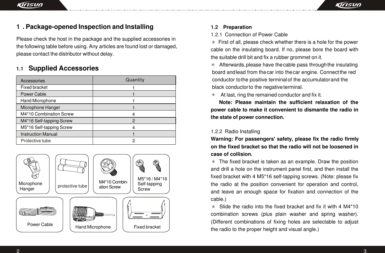
![11108. Public Address Press the button programmed for "Public Address", "b" will be displayed.Press the PTT button, the voice from the MIC of the radio will be directly sent to the external speakers through the interface on the back. Press the "Public Address" button again to disable the public address function. 9. Lone worker If Lone worker is set to be enabled, press the button "Lone worker" to enable the Lone Worker Mode. Start the Lone worker timer and when the preset Lone worker time is reached, the radio will alarm, after the alarm time, the radio will enter the Emergency Alarm Mode. In the Lone worker Mode, press the "Lone worker" button again to quit the Lone worker mode. In the Lone worker Mode, press the button programmed for "Lone worker reset" the specific button to select lone worker reset mode or any button (any button to select lone worker reset mode), the Lone worker timer will reset and start timing again. 12. Wired Clone Mode If the wired clone function is enabled, the radio will not quit after entering the wired clone mode. To return to normal user mode, the user needs to restart the machine. The operating steps go as follows: 1. Press [P1] buttons for power-on until show "C" and enter the software or send Your own ID or background voice to your partner or the system. In the Emergency Alarm Mode, press the button "Emergency Alarm Off" to quit the Emergency Alarm Mode and disable the alarm tone or stop sending it and resume normal operation. 11. Remote kill, stun, activate and revive If the radio received DTMF code programmed as remote stun, the radio will enter the remote stun status, after replying according to the setting, "u" will be displayed. The radio can only receive signals and cannot send signals. If the radio received DTMP code programmed as remote un-stun, the radio will quit the remote stun status and enter normal operation. If the radio received DTMF code programmed as remote kill, the radio will enter the remote kill status, after replying according to the setting, "h" will be displayed. The radio cannot send or receive signals. If the radio received DTMP code is programmed as revive, the radio will quit the remote kill status and enter normal operation. 10. Emergency Alarm Press the button programmed for "Emergency Alarm" (the time of pressing must be longer than the de-bounce time of the emergency alarm switch) to enter the Emergency Alarm mode. "E" will be displayed. You can set alarm tone according to the programming](https://usermanual.wiki/Kirisun-Communication/PT800001/User-Guide-1154788-Page-9.png)
![12 13 2. Connect the slave radio with the wired clone cable first, and then turn on. 3. Press button [P2] on the master radio for starting clone. During transmitting the data, the master radio lightens red, and the slave radio lightens green and indicates "P". After the slave radio recei- -ving all the data, the red light on the master radio is off, and the slave radio restarts. 4. You can keep cloning according to step 3 above. 13. Trouble Shooting Guide ProblemPower on FailurePhase lock loop unlocked (Beeping)No talkback No receiving signal SolutionA. The power cable is not connected with the accumulator or the host reliably. Please connect the power cable reliably.B. The protective tube of power cable is burnt out. Please change it.C. The power button is of poor contact. Please change the silica gel button or PCB button.D. The rechargeable battery is out of power. Please recharge or change a new one.E. CPU is broken, Please change the IC.A. Channel frequency beyond the range, reset channel data.B. The crystal X1 of phase lock loop is broken. Please change it.C. The oscillator tube is broken. Please change it.D. The IC3 of phase lock loop is broken. Please change IC.A. The frequency is not right. Please reselect the channel of the same frequency.B. The CTCSS/DCS code is not the same. Please reset it.C. It is out of the effective communication range.A. The antenna is not in good contact. Please fasten the antenna head.N Problem SolutionThe red transmission Indicator lights but no sound is heard.The green receiving indicator lights but no sound is heard.10B. The high-frequency amplifying tube Q18 is broken. Please change it.C. The squelch level is set to high Please reset the squelch level.D. The mixed tube Q19 is broken. Please change it.E. The FM IC6 is broken. Please change IC.A. Power module IC1 damaged, no power output, please change the module.B. MIC damaged, please change it.A. The speaker is broken. Please change it.B. The audio power amplifierIC7 is broken. Please change IC.14. Major Specifications Frequency Range: 136MHz~174MHz 438MHz~490MHz 400 -450 470MHz~512MHz Channel Number: 8 Channel Spacing: 25kHz (wide band)/12.5kHz (narrow band)Operating Voltage: 13.6V Dc 10%Operating Temperature: -25 -+55External Dimension: machine only: 150mm*53mm*130mm; plus fixed bracket: 165mm*62mm*130mmWeight: machine only: 1030g; Plus fixed bracket: 1310gMHz MHz clone mode. If the function is disabled, it will enter the user mode.N561234O.O.](https://usermanual.wiki/Kirisun-Communication/PT800001/User-Guide-1154788-Page-10.png)