Kirisun Communication TM84001 DMR Mobile Radio User Manual
Kirisun Communications Co., Ltd DMR Mobile Radio Users Manual
Users Manual
TM840 DMR Mobile RadioQuick User Guide

TM840 DMR Mobile RadioQuick User Guide
Quick User Guide
TM840
DMR Mobile Radio
We are very grateful for your purchasing KIRISUN DMR Mobile Radio
produced by Kirisun Communications Co., Ltd.
We believe KIRISUN DMR Mobile Radio, which always incorporates
the latest technology, can bring great convenience to your life and
work.
We also believe that the quality and function of KIRISUN DMR Mobile
Radio can meet your demands for reliable communication.

TM840 DMR Mobile RadioQuick User Guide
1
1 Safety Information
The government bans on operation the radio transmitter without permission in the jurisdiction
scope. Illegal operation will punished with fine or arrest. This product can only be maintained
by the professional technicians.
Safety: It’s very important for users to realize the generally dangerous of using the radio.
Warning: Please turn off the radio when you are refueling in the explosive atmosphere (such
as gas, dust and smog, etc.) or park at the gas station.
TM840 DMR Mobile Radio Quick User Guide
2
2 First Use
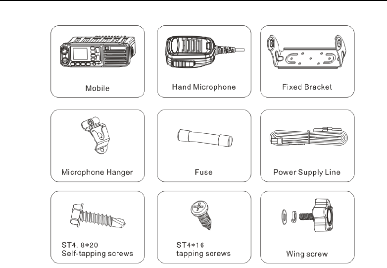
2.1 Unpacking and Checking
Please unpack carefully and check all the items listed in the following table before discarding the
packing material. If any damage or loss occurs during shipment, please contact your dealer.
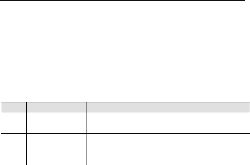
2.1.1 Standard Accessories
No.
Material
Quantity
1
Mobile
1
2
Hand Microphone
1
3
Fixed Bracket
1
4
Power Supply Line
1
5
Fuse
2
6
Microphone Hanger, with two ST4*16tapping screws
1

TM840 DMR Mobile RadioQuick User Guide
3
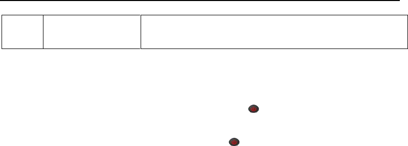
7
Plastic handle screw, contain matching flat washer and spring
washer
2
8
ST4.8*20 Self-tapping screws
6
9
Certificate of Approval
1
10
Quick User Guide
1
TM840 DMR Mobile Radio Quick User Guide
4

TM840 DMR Mobile RadioQuick User Guide
5
2.2 Preparing Your Mobile for Use
2.2.1 Installing your Mobile
1)Using six ST4.8*20 self-tapping self-drilling screws to fasten the bracket at the suitable place
inside the vehicle.
2)Using two Plastic handle screw to fasten the mobile on the bracket.
3) Connect the Power Supply Cable
First, arrange the 5 meter power cable (First, find that if there is a hole on the thermal baffle can
cross the power line. If there don’t have one, please drill a hole use the suitable drill bit and put on
rubber hole. Then let the power line through the thermal baffle into the engine compartment), and
connect the engine battery or other power supply to the open end (the power supply can’t exceed
16 Volt). Attention that the red line connect positive pole, the black line connect the negative pole.
Put in the suitable protective tube (random provided, please apply the protective tube from the
suppliers if you change it in the late, avoid causing other damage), put the plug insert the power
interface socket at the tail of turn-table.
4)Connect the Antenna

TM840 DMR Mobile Radio Quick User Guide
6
5)Connect the hand Microphones
Install hand microphone
Put the direction indicative plane of the hand microphone plug on the top and insert it into the
microphone interface of the mobile. Then clockwise rotate the self-lock cover on the microphone
plug until the self-lock cover against the card slot. At this moment, please press down a little bit
and continue rotate in clockwise until it can’t be rotated.
Uninstall hand microphone
Anticlockwise rotate the self-lock cover on the hand microphone until you can’t be rotated, then
pull the plug out.
Install Microphone Hanger Clip
Using two ST4*16 tapping screw to install the microphone Hanger clip at the place where it is
convenient for your use (the microphone and the microphone line should install at the place
doesn’t impact the safe drive), put the hand microphone hang on the microphone hanger.
TM840 DMR Mobile RadioQuick User Guide
7
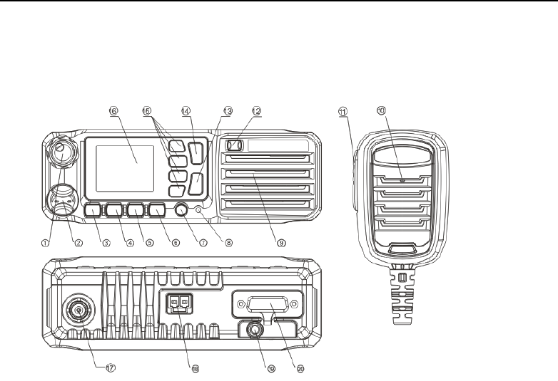
3 Product Overview
3.1 Control Parts Introduction

TM840 DMR Mobile Radio Quick User Guide
8
No.
Part Name
No.
Part Name
1
Volume Control Knob
11
PTT Key(Hand Microphone)
2
Microphone/Programming Cable Interface
12
Emergency Button
3
The Menu/Ok Button
13
Hook off Key
4
Up Key
14
Dial Key
5
Down Key
15
P1~P4 (Programmable Keys)
6
Return Button
16
LCD Display
7
On/Off Button
17
Antenna Connector
8
LED Indicator
18
Power Cable Connector
9
Speaker
19
GPS Antenna Connector
10
Microphone
20
26 Pin Connector
TM840 DMR Mobile RadioQuick User Guide
9
3.2 Programmable Buttons
For the convenience of users to operate the radio according to their own habits, the following buttons
can be programmed as short cuts to radio functions by dealer.
P1 to P4 can be programmed to “long press” and short press.
Note:
Short Press:Pressing and releasing rapidly.
Long Press: Pressing and holding for the programmed duration. (This time can be set via the
programming settings)
No.
Shortcut Keys
Description
1
None
No function. The error alert will be heard when the key
pressed.
2
High/Low
Toggles power level between high and low.
3
Monitor
Press monitor key to enter to “carrier squelch” mode when the
current channel is with CTC/DCS, thus the radio will unmute

TM840 DMR Mobile Radio Quick User Guide
10
when receiving carrier.
4
Squelch Off
To always unmute the speaker no matter whether carrier is
present or not. (Analog mode).
5
Squelch Level
Adjust the signal stress required for the radio to unmute.
6
Scan
Toggles scan on or off. To receive signal from other channels
7
LCDBrightness
Adjust the brightness level by entering to "LCD Brightness".
8
LCD Backlight Type
To adjust off time of LCD backlight in this option.
9
Repeater/Talkaround
Toggle between using a repeater and communicating directly
with another radio.
10
Zone Selection
To change the current call zone.
11
Home Screen
To quickly return to the home screen.
12
Nuisance Delete
To temporarily ignore unwanted channel activity.
13
Scramble/Encryption
Toggles scramble/encryption on or off.
14
Contacts
Provides directly access to the contact list
15
Message
Selects the message menu. Only works on digital mode.

TM840 DMR Mobile RadioQuick User Guide
11
16
Call log
Selects the call log menu. Only valid in digital mode.
17
Monitor Channel
On/off monitor channel. Exit monitor channel function when
pressing PTT.
18
Permanent Monitor
Channel
On/off permanent monitor channel. Don’t exit monitor channel
function when pressing PTT.
19
Sending Interrupt
To interrupt other user to initiating a call at the current channel.
20
Public Address1
Allows the user to toggle the audio routing from incoming audio
or radio microphone to the connected external public address
(PA) speaker at rear port 1.
21
Public Address2
Allows the user to toggle the audio routing from incoming audio
or radio microphone to the connected external public address
(PA) speaker at rear port 2.
22
External
Alarm/Speaker/Light
When the mobile received emergency call/alarm, call alert or
private call and without operation during the programmed time,
the valid level will output from GPIO. The level can drive the
TM840 DMR Mobile Radio Quick User Guide
12
external alarm device (light or speaker) connected to GPIO to
alarm.
4 Basic Operation
4.1 Powering On/Off the Radio
In the power off status, long press the Radio On-Off button to power on the mobile. The power
on screen will be shown, backlight will light and the power on alert will be heard.
In the power on status, long press Radio On-Off button until power off screen is shown to power
off the mobile.
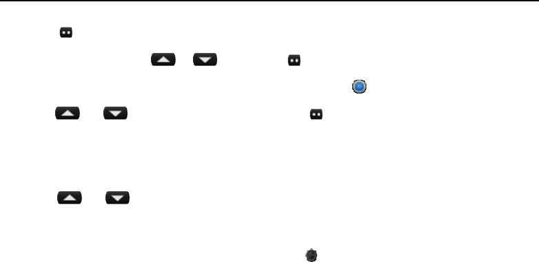
4.2 Selecting a Zone
A Zone is a group of channels exhibiting the same property, allowing users quickly switch from a
channel group to a different channel group. The radio can be set to have up to 248 zones, each with
a maximum of 128 channels.
You may select a zone through the following way:
TM840 DMR Mobile RadioQuick User Guide
13
1)Press key to enter the main menu in home screen.
2) Access to zone item by or , then press to select.
3) All the zones are listed here. The current zone is indicated by .
4) Press or key to required zone and press to select.
5) This display shows "Zone Selected "and return to selected zone screen.
4.3 Selecting a Channel
Pressing or key to select channel on home screen.
4.4 Adjusting the Volume
After the radio power on, rotate the volume knob clockwise to increase radio volume or
counter-clockwise to decrease the volume.
4.5 Making a Call
You can initiate a call by following method.

TM840 DMR Mobile Radio Quick User Guide
14
When a call is initiated, the red LED lights on. The call type (private call icon , group call icon ),
alias or ID and outgoing call icon is displayed on the LCD
4.5.1 Initiate a Call to the Default Contact
In the home screen, hold down the PTT key to initiate a call to the default contact which has be set
for the current channel in CPS software. The contact can be set to private call, group call, or all call
by CPS.
4.5.2 Selecting a Contact and Initiate a Call
You can also make a call via contacts. Enter contact list menu and select one specific contact, then
hold down PTT to initiate a call.
4.5.3 Manual Dial and Initiate a Call
You can also make a call by "Manual Dial". Enter the "Contacts" menu and then enter "Manual Dial"
sub-menu, directly enter contacts’ ID number, and press PTT key to initiate a call.
4.6 Receiving and Answering the Call

TM840 DMR Mobile RadioQuick User Guide
15
When a call is received in the standby mode:
Green LED indicator lights on. The call type (private call icon , group call icon ), alias or ID and
incoming call icon is displayed on the LCD.
You can hold down PTT to call back to current contact within the hang time duration.
Note:
To receive a group call, your radio must be configured as part of that group. (Dealer set it via CPS).
You cannot respond to an All Call.
TM840 DMR Mobile Radio Quick User Guide
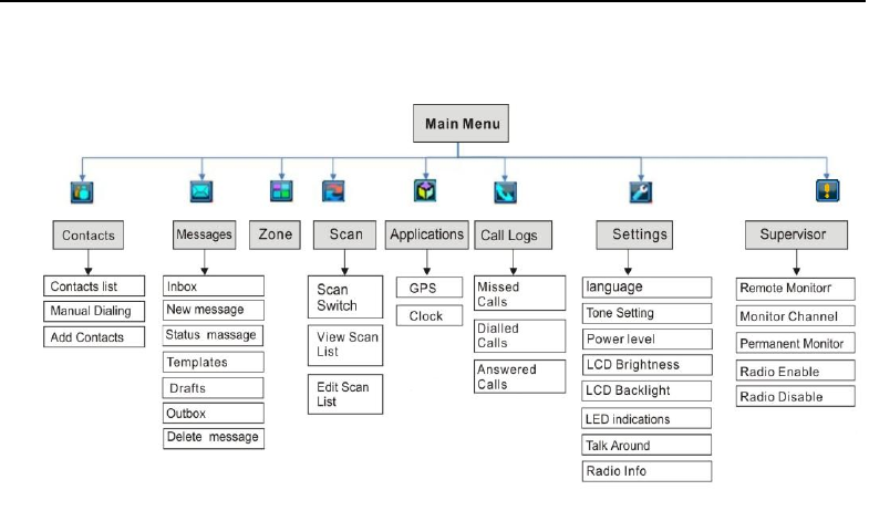
16
5 Menu Bar
TM840 DMR Mobile RadioQuick User Guide
17
6 Status Indicator
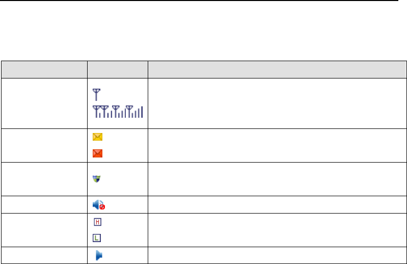
6.1 LCD Icon
Icon Name
Icon
Radio Status
Signal Strength
Indication
No signal
The number of bars indicates the received signal strength.
Four bars are the strongest.
Message
There is new message/unread message.
Message inbox is full.
Encryption or
Scrambling
Analog scrambling or digital encryption is available.
Speaker Mute
Speaker is muted.
Transmitting
Power
High TX power for the current channel
Low TX power for the current channel
Channel
Channel is being monitored
TM840 DMR Mobile Radio Quick User Guide
18
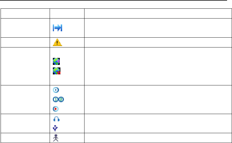
Monitoring
Talk Around
Talk-around mode is active for repeater mode; or the current
channel is direct mode.
Emergency Alarm
Emergency alarm mode
GPS feature
GPS feature is available and the radio is receiving valid GPS
data.
GPS feature is available, but the radio has not got valid
location information.
Scan
Scanning is in process.
Scanning stops on apriority channel 1 or apriority channel 2.
Scanning stops on anon-priority channel.
Accessory
Connecting Status
External MIC/Speaker is connected.
USB cable is connected
Lone Work
Lone work function is enable
TM840 DMR Mobile RadioQuick User Guide
19
6.2 LED Indicator
LED Indicator
Radio Work Status
Red LED lights on
Radio is transmitting.
Green LED lights on
Radio is receiving (voice, short message, or data) or there is an
activity on the channel.
Orange LED lights on
The radio is in the call hang time period, you can press PTT to talk
back while the orange LED lights on.
Orange LED flashes
Radio is in emergency status; or there is a missed call / incoming
call alert; or the radio is scanning.
Red LED flashes
Radio is receiving emergency alarm.

TM840 DMR Mobile Radio Quick User Guide
20
7 Maintenance and Cleaning
In order to derive optimum performance and long service life from this product, please read the
following maintenance and cleaning information carefully for better daily care and clean.
7.1 Maintenance
Please do not puncture or scratch the mobile with hard objects.
Please make sure the mobile located at the good ventilation and good heat dissipation place for
every components working normally.
Please do not put unrelated objects on top of mobile to make sure the efficient heat dissipation.
Please do not soak the mobile in all kinds of etchant, solution or water.
7.2 Cleaning
Please regular do the daily cleaning for the mobile. Wiping away the dust attached to the parts of
mobile by using clean and dry lint free cloth or hairbrush, keep it clean and prevent bad contact.
If the key, control knob, display screen and interface became dirty, using non-woven fabrics dipped
with neutral detergent to clean them. Don’t use the strong corrosive chemicals like decontaminant,

TM840 DMR Mobile RadioQuick User Guide
21
alcohol, spray or oil preparations and so on. After cleaning, must ensure that the vehicle terminal
completely dry, otherwise don’t use it.
Note:Please turn off the power supply of the vehicle terminal before your cleaning.
FCC Statement
This device complies with part 15 of the FCC Rules. Operation is subject to the following two
conditions: (1) This device may not cause harmful interference, and (2) this device must accept any
interference received, including interference that may cause undesired operation.
This equipment
generates or uses radio frequency energy. Changes or modifications to this
equipment may cause harmful interference unless the modifications are expressly approved in the
instruction manual. The user could lose the authority to operate this equipment if an unauthorized
change or modification is made.

TM840 DMR Mobile Radio Quick User Guide
22
FCC Radiation Exposure Statement:
This equipment complies with FCC radiation exposure limits set forth for a controlled environment.
This equipment should be installed and operated with minimum distance 0.7m between the radiator
antenna & your body.
This transmitter must not be co-located or operating in conjunction with any other antenna or
transmitter.
Note: This equipment has been tested and found to comply with the limits for a Class B digital device,
pursuant to part 15 of the FCC Rules. These limits are designed to provide reasonable protection
against harmful interference in a residential installation. This equipment generates uses and can
radiate radio frequency energy and, if not installed and used in accordance with the instructions,
may cause harmful interference to radio communications. However, there is no guarantee that
interference will not occur in a particular installation. If this equipment does cause harmful
interference to radio or television reception, which can be determined by turning the equipment off
and on, the user is encouraged to try to correct the interference by one or more of the following
measures:

TM840 DMR Mobile RadioQuick User Guide
23
—Reorient or relocate the receiving antenna.
—Increase the separation between the equipment and receiver.
—Connect the equipment into an outlet on a circuit different from that to which the receiver is
connected.
—Consult the dealer or an experienced radio/TV technician for help.
IC RSS warning
This device complies with Industry Canada licence-exempt RSS standard (s). Operation is subject to
the following two conditions: (1) this device may not cause interference, and (2) this device must
accept any interference,including interference that may cause undesired operation of the device.
Le présent appareil est conforme aux CNR d'Industrie Canada applicables aux appareils radio
exempts de licence.
L'exploitation est autorisée aux deux conditions suivantes:
(1) l'appareil ne doit pas produire de brouillage, et
(2) l'utilisateur de l'appareil doit accepter tout brouillage radioélectrique subi, même si le brouillage
est susceptible d'en compromettre le fonctionnement.

TM840 DMR Mobile Radio Quick User Guide
24
Under Industry Canada regulations, this radio transmitter may only operate using an antenna of a
type and maximum (or lesser) gain approved for the transmitter by Industry Canada. To reduce
potential radio interference to other users, the antenna type and its gain should be so chosen that,
the equivalent isotropically radiated power (e.i.r.p.) is not more than that necessary for successful
communication.
Conformément à la réglementation d'Industrie Canada, le présent émetteur radio peut fonctionner
avec une antenne d'un type et d'un gain maximal (ou inférieur) approuvé pour l'émetteur par
Industrie Canada. Dans le but de réduire les risques de brouillage radioélectrique à l'intention des
autres utilisateurs, il faut choisir le type d'antenne et son gain de sorte que la puissance isotrope
rayonnée équivalente (p.i.r.e.) ne dépasse pas l'intensité nécessaire à l'établissement d'une
communication satisfaisante.
IC Radiation Exposure Statement:
This equipment complies with IC RF radiation exposure limits set forth for an controlled environment.

TM840 DMR Mobile RadioQuick User Guide
25
This transmitter must not be co-located or operating in conjunction with any other antenna or
transmitter.This equipment should be installed and operated with minimum distance 0.7m between
the radiator & your body.
IC exposition aux radiations:
Cet équipement est conforme avec IC les limites d'exposition aux rayonnements définies pour
contrôlé environnement. Cet émetteur ne doit pas être co-localisés ou fonctionner en conjonction
avec une autre antenne ou émetteur.Cet équipement doit être installé et utilisé avec un minimum de
0,7 m de distance entre le radiateur et votre corps.
Mandatory Safety Instruction to Installers and Users
Use only manufacturer or dealer supplied antennas.
Antenna Minimum Safe Distance:70 cm(27.6 inches),50% duty Cycle.
Antenna Gain: 0dBi referenced to a dipole.
The Federal Communications Commission has adopted a safety standard for human exposure to
RF(Radio Frequency) energy which is below the OSHA(Occupational Safety and Health Act) limits.
Antenna Mounting: The antenna supplied by the manufacturer or radio dealer must not be mounted

TM840 DMR Mobile Radio Quick User Guide
26
at a location such that during radio transmission, any person or persons can come closer than the
above indicated minimum safe distance to the antenna, i.e. 70cm(27.6 inches), 50% duty Cycle.
To comply with current FCC RF Exposure limits, the antenna must be installed at or exceeding the
minimum safe distance shown above, and in accordance with the requirements of the antenna
manufacturer or supplier.
Vehicle installation: The antenna can be mounted at the center of a vehicle metal roof or trunk lid, if
the minimum safe distance is observed.
Antenna substitution: Do not substitute any antenna for the one supplied or recommended by the
manufacturer or radio dealer.
You may be exposing person or persons to excess radio frequency radiation.
You may contact your radio dealer or the manufacturer for further instructions.
You, as the qualified end-user of this radio device must control the exposure conditions of
bystanders to ensure the minimum separation distance (above) is maintained between the antenna
and nearby persons for satisfying RF Exposure compliance. The operation of this transmitter must
satisfy the requirements of Occupational/Controlled Exposure Environment, for work-related use,

TM840 DMR Mobile RadioQuick User Guide
27
transmit only when person(s) are at least the minimum distance from the properly installed,
externally mounted antenna. Transmit only when people outside the vehicle are at least the
recommended minimum lateral distance away from the antenna/vehicle.