Kirisun Communication TP620 Two Way Radio User Manual TP620
Kirisun Communications Co., Ltd Two Way Radio TP620
user manual
TP620 Digital Portable Radio Quick Instruction Manual
II
FCC ID:Q5ETP620
II
Quick Instruction Manual
TP620
We are very grateful for your purchasing KIRISUN brand two-way radios produced
by Kirisun Communications Co., Ltd.
We believe KIRISUN two-way radio, which always incorporates the latest
technology, can bring great convenience to your life and work.
We also believe that the quality and function of KIRISUN two-way radio can meet
your demands for reliable communication.
Quick Instruction Manual
Frequency:400-470MHz

1
Declaration of Conformity
CE0700!
We, Kirisun Communications Co.,Ltd. 3-6Flrs, ROBETA Building, No.1, QiMin Road, Song Ping
Shan Area, Science&Industry Park, Nanshan District Shenzhen 518057 P.R. China
Declare on our sole responsibility that this equipment complies with the Annex IV of Council
Directive 1999/5/EC on radio equipment and telecommunications equipment and the mutual
recognition of their conformity, and that any applicable Essential Test Suits measurement has been
performed.
Description of equipment: UHF DMR Portable
Model No.: Kirisun/TP620
This compliances is based on conformity with the following harmonized standards or documents:
(1).ETSI EN 300 086-2 V1.3.2
ETSI EN 300 113-2 V1.5.1
(2). ETSI EN 301 489-1 V1.9.2(2011-09)
ETSI EN 301 489-5 V1.3.1(2002-08)
(3) EN 60950-1:2006+A11:2009+A1:2010+A12:2011
Quick Instruction Manual

TP620 Digital Portable Radio Quick Instruction Manual
2
(4) EN 50385:2002
FCC
We, Kirisun Communications Co.,Ltd. 3-6Flrs, ROBETA Building, No.1, QiMin Road, Song Ping
Shan Area, Science&Industry Park, Nanshan District Shenzhen 518057 P.R. China
Declare on our sole responsibility that this equipment complies with the FCC Part15 rules
These limits are designed to provide reasonable protection against harmful interference in a
residential installation. This equipment generates and can radiate radio frequency energy and, if not
installed and used in accordance with the instructions, may cause harmful interference to radio
communications. However, there is no guarantee that interference will not occur in a particular
installation. If this equipment does cause harmful interference to radio or television reception,
which can be determined by turning the equipment off and on, the user is encouraged to try to
correct. The interference by one or more of the following measures:
● Reorient or relocate the receiving antenna. Increase the separation between the equipment
and receiver.
● Connect the equipment into an outlet on a circuit different from that to which the receiver is

3
connected.
● Consult the dealer or an experienced radio/TV technician for help. Operation is subject to the
following two conditions: 1.This device may not cause harmful interference, and
2. This device must accept any interference received, including interference that may cause
undesired operation.
Note:” Changes or modifications to this unit not expressly approved by the party responsible for
compliance could void the user’s authority to operate the equipment.”
1. Safety
Before using this radio, read this operating instruction carefully for safe and convenient usage.
This product can only be maintained by the professional technicians. Do not disassemble the radio
by yourself.
To avoid of the problems caused by electromagnetic interference or electromagnetic compatibility,
turn off the radio in any facilities where posted notices instruct you to do so, such as hospital and
other health care facilities. And when on board an aircraft, turn off the radio if instructed to do so too.
Quick Instruction Manual

4
In the vehicle with an air bag, do not place the radio in the area over an air bag or in the air bag
deployment area.
Turn off the radio before entering any area with a potentially explosive atmosphere or blasting caps.
Do not operate the radio, disassemble or charge the battery in the potentially flammable and
explosive atmosphere (such as gas station, coal gas station, etc.).
Do not place the radio under the direct sunlight or near the area with heating devices.
Do not place the radio in the area with great dust, moisture or drips, or on the unstable surface.
Contact us or your local dealer for help if you want to redevelop or modify the radio.
Do not use any portable radio that has a damaged antenna. If a damaged antenna comes into
contact with your skin, a minor burn can result.
Make sure the antenna is correctly installed when using. The radio without antenna may cause
damage in the process of transmission.
2. First Use
2.1 Unpacking and Checking
Standard Accessories
Please unpack carefully and check all the items listed in the following table before discarding the
Quick Instruction Manual
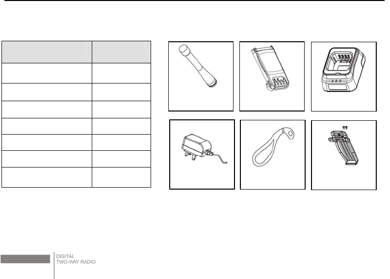
5
packing material. If any damage or loss occurs during shipment, please contact your dealer.
Item Quantity
Antenna 1
Belt Clip 1
Charger 1
Battery 1
Hand Strap 1
Power Adapter 1
Instruction Manual 1
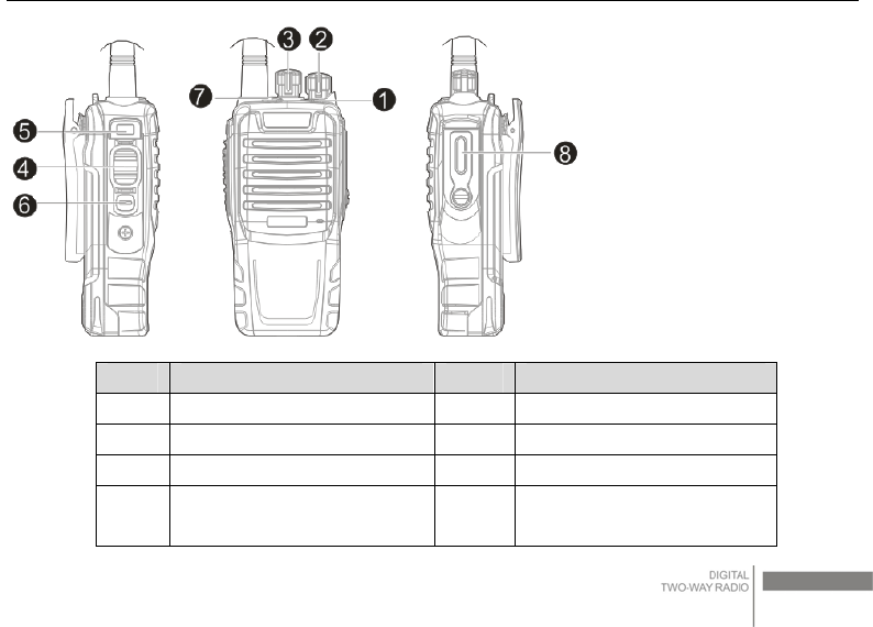
2.2 Product Overview
Identification of buttons
Battery
Antenna Charger
Hand strap
Power Adapter
Belt Cli
p
and
Screws
Quick Instruction Manual
6
No Part Name No Part Name
1 LED Indicator 5 Side Button1
2 Power/Volume Switch 6 Side Button2
3 Channel Knob 7 Top Button
4 PTT Button 8 External speaker /
microphone interface
Quick Instruction Manual

7
Programmable Buttons
Authorized Dealer can program the programmable buttons as shortcuts to various radio features.
Each button can has two features and can be activated through Long Press or Short Press.
LED Status Indicator
The LED indicator shows the operational status of your radio.
Solid red – Radio is transmitting
Solid green- Radio is powering up or receiving a non-privacy-enabled call or data, or detecting
activity over the air.
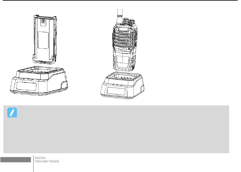
2.3 Preparing your product for use
Charging the Battery
Note:
Short Press – Pressing and releasing quickly
Long press – Pressing and holding for the programmed duration
Quick Instruction Manual

8
Please refer to the following steps to charge your batter.
1) Plug the adaptor in the rear power jack of the intelligent charger, and plug the adaptor into the
suitable AC socket. The three LED lights will flash for about one second and turn green when
everything is properly set.
2) Put the battery or the radio with battery into the charger, and please turn off the radio before
charging.
3) Make sure the battery is properly attached to the charger. The charging begins when the red
light is on.
4) The red light is off after five-hour charging, and then the green light is on, indicating the charging
is completed.
Quick Instruction Manual
9
.
Note:
The yellow light flashing indicates abnormality in charging temperature or in the circuit, and
the charger will then enter the state of protection. During this state, do not impose charging
anymore and take out the battery before unplugging the charger.
Please use only the charger and battery provided by Kirisun.
Quick Instruction Manual
10
Charging LED Indicator
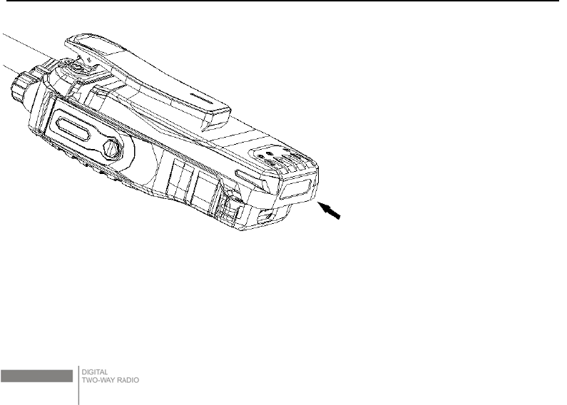
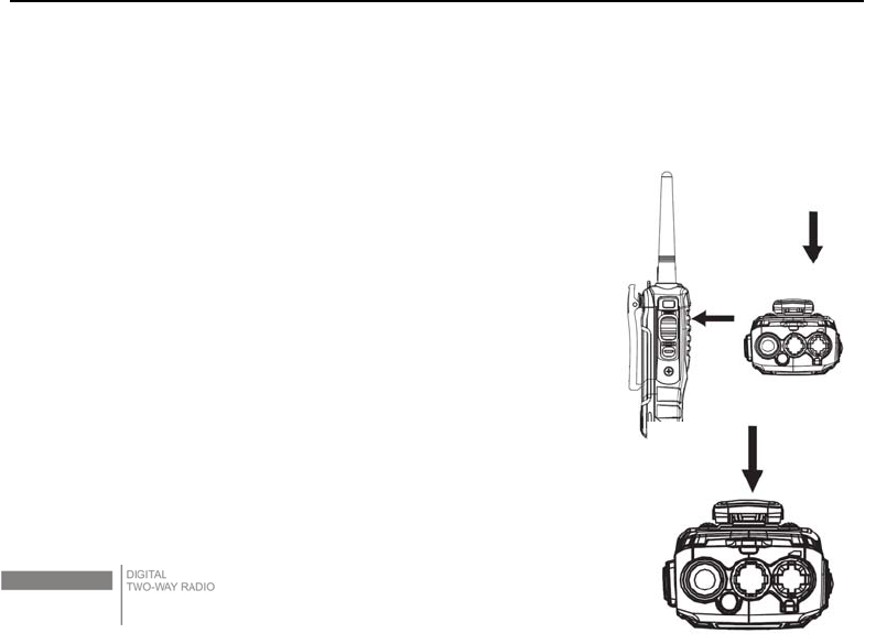
Installing/Uninstalling the Battery
Installing the Battery
Press the top of the belt clip, and align the battery with the slots on the back of the radio. Press the
battery firmly, and slide upward until the latch snaps into place.
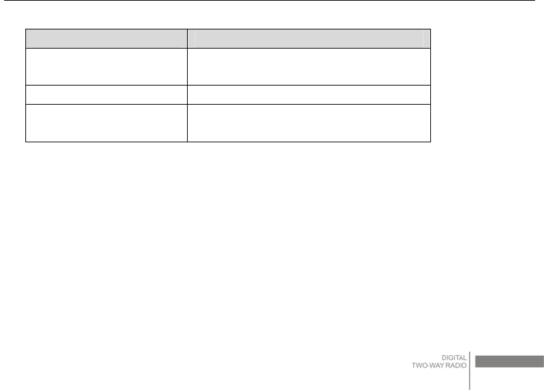
LED Charging Status
Yellow light flashes. Abnormality in charging temperature or in
the circuit.
The red led lights. The battery is in charging.
The green led lights. The battery is full charged or Standby(no
load)
Quick Instruction Manual
11
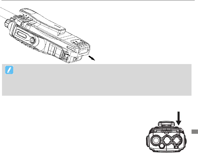
Uninstalling the Battery
For detaching the battery, push downward the battery latch at the radio bottom and then push the
battery in the direction of the arrow shown in the picture until the battery is completely detached from
the radio.
Quick Instruction Manual
12
3. Basic Operation
Powering on/off
Turn the power/volume knob clockwise for powering on. If the dealer
Note:
Please do not throw the short-circuit battery terminal or battery into fire. Please do not
short-circuit the battery terminal or throw the battery into fire.
Do not disassemble the battery casing by yourself
Quick Instruction Manual
13
set an alert tone, the radio will make a beep. Turn the power/volume knob counterclockwise for
powering off.
Adjusting the Volume
To increase the volume, turn the Volume Knob clockwise. To
decrease the volume, turn this knob counterclockwise.
Selecting a Channel
Turn the channel knob to select the channel you need. A sound from the
speaker indicates that the valid signal is received.
Quick Instruction Manual
14
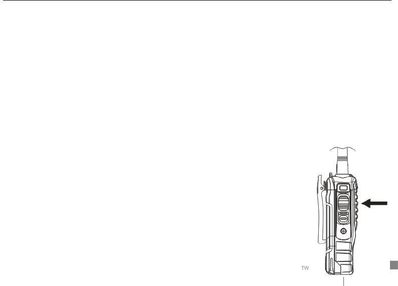
Push-To-TALK (PTT) Button
The PTT button in the radio’s side (Push To Talk, press to talk), this button have functions below:
To initiate a new call;
In the talking process, you can call other user of this channel.
Operation Steps;
cm) from your mouth. Then press and hold the PTT
button and speak clearly into the microphone. Release PTT button to receive.
Selecting a Zone
A zone is a group of channels. Your radio supports up to a maximum 2
zones with every zone supporting up to a maximum of 16 channels.
Procedure:
1) Press the programmed zone button
2) A positive alert tone indicates the radio switched from zone 1 to zone 2.
Quick Instruction Manual
Hold the radio vertically 1 inches (2.5

15
A negative alert tone indicates the radio switched from zone 2 to zone 1.
Selecting a Radio ChannelProcedure:
Once the required zone is programmed (if you have multiple zones in your radio), turn the Channel
Selector Knob to select the channel.
4. Making/Receiving a Call
Making a Call
Hold down the PTT button to initial a call to the default contact which has set for current channel in
programming software. The contact can be set to private call, group call or all call by programming
software.
Receiving and Answering a Call
When a call is receive, the green LED lights on, you can hear the talking. After receiving, you can
press and hold on the PTT button to reply this call within call hang time duration.
Quick Instruction Manual
16
5. Other Functions
Except making a call and receiving a call, the radio also supports many other functions. These
functions need to be programmed before using. You can connect your local dealer to use these
functions.
Functions
Send a Message You can send a quick message by one touch
button
Radio Enable encode Allows stolen/lost radios to be enabled over the
air.
Radio Disable encode Allows stolen/lost radios to be disabled over the
air.
Radio Check Decode It checks whether radios are active on system
without disturbing user.
Call Alert Enables a user to page another and request a
return call when convenient.
Remote Monitor Decode Enables supervisor radios to listen in on remote
radios to maximize employee safety and
Quick Instruction Manual
17
instantly assess situation.
Digital Encryption Enhance communication security.
Emergency Variety emergency calls can be confirmed to
maximize employee safety.
Scan A scan helps ensure all relevant calls are heard.
DTMF Encode and
Decode
DTMF function can allow users to send a PTT ID
or realize kinds of calls.
. .
6. Troubleshooting
No. Problem Causes and Solutions
1 Powered-on Failure
A. The battery may be used up. Charge or change the battery
to try again.
B. The On/Off key may be in poor contact. Clean the metal
dome with alcohol and try again.
Quick Instruction Manual

18
C. The power binding post isn’t connected with battery.
Re-install it and try again.
2 Communication
Failure
A. The frequency settings may be different from others. Set
your TX/RX frequencies to be the same as others.
B. The CTCSS/CDCSS signaling maybe different from others.
Set your CTCSS/CDCSS signaling to be the same as others.
C. Beyond the radio’s coverage area. Your place may be too
far from the others.
3 Failed Receiving of
Signal
A. The antenna may get loose or may be improperly installed –
Re-install the antenna.
B. The frequency settings may be different from others. Set
your TX/RX frequencies to be the same as others.
C. Beyond the radio’s coverage area. Your place may be too
far from the others.
Quick Instruction Manual
19
4
The LED lights up
solid green without
any voice received
A. Check whether the volume level is at its lowest or not.
Increase the volume level and try again.
B. Check whether the speaker is broken or not. Change the
speaker and try again.
5 Failed CPS
Programming
A. Wrong wire connection. Check and try again.
B. Check if the USB driver is installed or not. Install a USB
driver and try again.
C. Poor contact of the earpiece interface board – Change the
earpiece interface board and try again.
Quick Instruction Manual
SAFETYTRAININGINFORMATION
Your radiogeneratorsRFelectromagneticenergyduring
transmitmode.Thisradioisdesignedforandclassifiedas“OccupationalUseOnly”,meaningitmustbeusedonlyduringthe
courseofemploymentbyindividualsawareofthehazards,andthewaysToMinimizeSuchhazards.ThisradioisNOTintended
forusebythe“GeneralPopulation”inanuncontrolledenvironment.ThisradiohasbeentestedandcomplieswiththeFCCRF
exposurelimitsfor“OccupationalUseOnly”.Inaddition,your
radiocomplieswith
thefollowingStandardsandGuidelineswithregardtoRFenergyandelectromagneticenergylevelsandevaluationofsuch
levelsforexposuretohumans:
�
to Radio Frequency Electromagnetic Fields.
�American National Standards Institute (C95.1-1992), IEEE Standard for Safety Levels with Respect to Human
Exposure to Radio Frequency Electromagnetic Fields, 3 kHz to 300 GHz.
�American National Standards Institute (C95.3-1992), IEEE Recommended Practice for the Measurement of
Potentially Hazardous Electromagnetic Fields– RF and Microwave.
�The following accessories are authorized for use with this product. Use of accessories other than those (listed in the
instruction) specified may result in RF exposure levels exceed the FCC requirements for wireless RF exposure.
Toensureyou’reyourexposetoRFelectromagneticenergyiswithintheFCCallowablelimitsforoccupationaluse,always
adheretothefollowingguidelines
TheinformationlistedaboveprovidestheuserwiththeinformationneededtomakehimorherawareofRFexposure,
andwhattodotoas‐surethatthisradiooperateswiththeFCCRFexposurelimitsofthisradio.
ElectromagneticInterference/Compatibility
Duringtransmissions, radiogeneratesRFenergythatcanpossiblycauseinterference
withotherdevicesorsystems.Toavoidsuchinterference,turnofftheradioinareaswheresignsarepostedtodoso.DONOT
operatethetransmitterinareasthataresensitivetoelectromagneticradiationsuchashospitals,aircraft,andblastingsites.
Occupational/ControlledUse
Theradiotransmitterisusedinsituationsinwhichpersonsareexposedasconsequenceoftheiremploymentprovided
thosepersonsarefullyawareofthepotentialforexposureandcanexercisecontrolovertheirexposure.
FCC OET Bulletin 65 Edition 97-01 Supplement C, Evaluating Compliance with FCC Guidelines for Human Exposure
Attention:
This radio complieswith IEEE and ICNIRP exposure limits for occupational/controlled RF exposure
emvironment at operating duty factors of up to 50% and is authorized by the FCC for occupational
use only. An appropriate warning lable is affixed to all units.
In order to comply with RF exposure requirements, a minimum distance of 2.5cm must be maintained
when held-to-face, and body-worn operations are restricted to the approved original acessories (belt clip).
Do not use this device when antenna shows obvious damages
Kirisun Communications Co., Ltd
Kirisun Communications Co., Ltd
Kirisun Communications Co., Ltd