Kirisun Communication TR85001 DMR Repeater User Manual
Kirisun Communications Co., Ltd DMR Repeater Users Manual
Users Manual
TR850 DMR Repeater Instruction Manual
II

TR850 DMR Repeater Instruction Manual
II
Instruction Manual
TR850
DMR Repeater
We are very grateful for your purchasing TR850 produced by Kirisun Communications
Co., Ltd. We believe TR850 can bring great convenience to your life and work.
TR850 DMR repeater which always incorporates the advanced technology and
exquisite craft, we hope that the quality and function of this product could make you
feel satisfied.

TR850 DMR Repeater Instruction Manual
II
Notice to User
◆ Please read this Instruction Manual carefully before any operation to this product.
When you start to use the product, we deem that you have read this manual carefully.
◆ Please save this Instruction Manual in a safe place for inference in need.
◆ In order to preserve your rights and interests, please fill in the Warranty Card
seriously and actually when you purchase this product, and ask for the valid purchasing
certificate.
◆ Kirisun and the authorized parties own the related intellectual property of all the
product parts include accessories. Any design and materials may not be modified, copied,
extracted or translated without the authorization of Kirisun or its authorized parties.
◆ Due to the update or modification of the product, Kirisun owns the right to change the
specifications of software and hardware described in this manual without further notice.
Specifications and information contained in this manual are for reference only.
◆ All described information in this manual are verified, if any missing or mistakes,
Kirisun reserves the rights to the interpretation of this manual.

TR850 DMR Repeater Instruction Manual
III
Safety Information
In order to use the indoor digital repeater effectively, please read the following
information.
◆This product can only be maintained by the professional technicians. Do not
disassemble the radio by yourself.
◆The repeater setting and mounting must be approved by the local Radio Management
Departments.
◆Installing the antenna of repeater must be do well of lightning protection, otherwise life
or property damage may be occurred.
◆Please use the qualified power, antenna, lightning protection device, power divider and
corresponding accessories and make sure they are installed correctly, otherwise
repeater damage will be occurred.

TR850 DMR Repeater Instruction Manual
I
Contents
1 Unpacking and checking .......................................................................................... 1
1.1 Standard Accessories .............................................................................................. 1
2 Radio Overview ....................................................................................................... 3
2.1 Power On/Off Button ................................................................................................ 5
2.2 ACCY Connector ..................................................................................................... 5
2.2.1 Pin Instruction .......................................................................................................... 5
2.2.2 External Connector Instruction ................................................................................. 7
2.3 LED Indicators ......................................................................................................... 8
3 Basic Operations ..................................................................................................... 9
3.1 Powering On/Off ...................................................................................................... 9
3.2 Voice and Data Transfer .......................................................................................... 9
3.3 IP Connecting .......................................................................................................... 9
3.4 Warning ................................................................................................................. 10
3.5 Programming Software .......................................................................................... 10
3.5.1 File Menu ............................................................................................................... 10
3.5.2 Model Menu ........................................................................................................... 11
3.5.3 Edit Menu ............................................................................................................... 11
4 Program Menu ....................................................................................................... 15
5 Installation Guide (refit guide) ................................................................................ 18
6 Frequently Asked Questions (FAQ) ....................................................................... 22
7 Recommend Duplexer Parameters ........................................................................ 23
TR850 DMR Repeater Instruction Manual
1
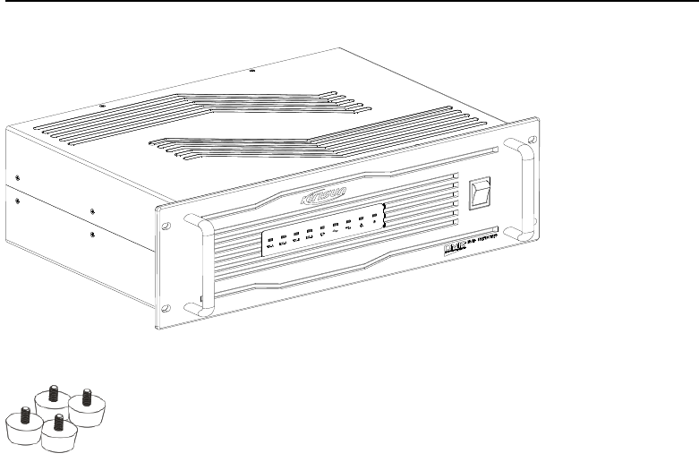
1 Unpacking and Checking
Please unpack carefully and check all the items listed in the following table before discarding the
packing material. If any damage or loss occurs during shipment, please contact your dealer.
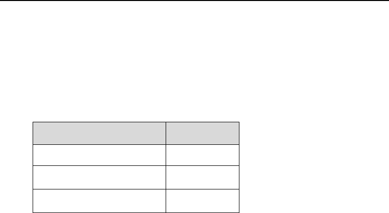
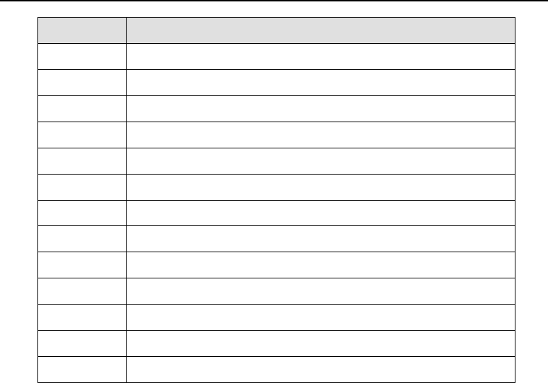
1.1 Standard Accessories
Item
Quantity
Repeater
1
Foot pad(4 pcs)
1
Instruction Manual
1
TR850 DMR Repeater Instruction Manual
2
TR850 DMR Repeater Instruction Manual
3
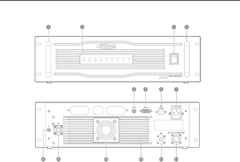
2 Radio Overview
TR850 DMR Repeater Instruction Manual
4
No.
Part Name
1
Handles
2
Frond Panel LED Indicators
3
Power Switch
4
GPS Antenna Connector
5
ACCY Connector
6
Network Connector(IP)
7
100-240V AC Cable Connector
8
GND Screw
9
Tx Connector
10
Fan
11
Cooler
12
RX Connector
13
13.6V DC Connector
TR850 DMR Repeater Instruction Manual
5
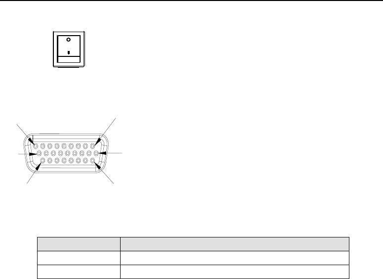
2.1 Power On/Off Button
Power on/off the repeater.
2.2 ACCY Connector
2.2.1 Pin Instruction
Pin
Instruction
PIN1
Undefined
PIN2
Undefined
1
9
10
18
19
26

TR850 DMR Repeater Instruction Manual
6
PIN3
Undefined
PIN4
GND
PIN5
ACC_MAP_ID2: It is used for test.
PIN6
ACC_MAP_ID1: It is used for test.
PIN7
Undefined
PIN8
GND
PIN9
+SPEAKER
PIN10
-SPEAKER
PIN11
MIC
PIN12
GND
PIN13
Undefined
PIN14
Undefined
PIN15
Undefined
PIN16
GND
PIN17
External PTT,High level is effective
PIN18
GND
PIN19
Undefined
PIN20
Undefined
PIN21
Undefined

TR850 DMR Repeater Instruction Manual
7
PIN22
PRGM_IO_7, External high level signal input
PIN23
Undefined
PIN24
Undefined
PIN25
Undefined
2.2.2 External Connector Instruction
The method to activate external PTT:
Short connect the Pin17 with Pin22 of VGA to activate external PTT. It can test the transmitting
signal of repeater.
Test Analog Receiving:
Short connect Pin5 with Pin22 of VGA.
Reset IP address:
Short connect PIN6 with PIN22 of VGA to reset the IP and gateway address to the IP address on
the label, but it will not change data of IP address and gateway address, The IP address and
gateway address will recover to configure address after restart.
TR850 DMR Repeater Instruction Manual
8
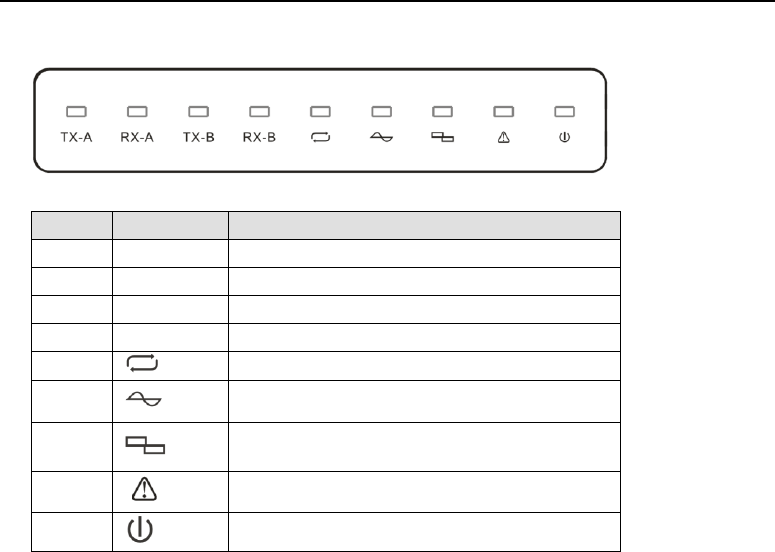
2.3 LED Indicators
No.
Indicator
Description
1
TX-A
Slot 1 transmitting indicator
2
RX-A
Slot 1 receiving indicator
3
TX-B
Slot 2 transmitting indicator
4
RX-B
Slot 2 receiving indicator
5
Repeater signal indicator
6
Analog mode indicator
7
Digital mode indicator
8
Alarm indicator
9
Power indicator

TR850 DMR Repeater Instruction Manual
9
3 Basic Operations
3.1 Powering On/Off
When the repeater is turned off, press the power switch " " to power on the repeater. Then the
light " "is on. After the system working normally, the light " "、" " indicates the
present working mode. Press to power off the repeater.
3.2 Voice and Data Transfer
The receiving and transmitting frequency are different on the repeater. Repeater will turn the weak
receiving signal into strong transmitting signal and transmit on the same channel. When
transmitting, the light is on. If it is analog signal, flashes, if it is digital signal,
flashes. The receiving and transmitting frequency and CDCSS/CTCSS can be set by CPS.
An analog channel or a smart analog/digital detecting channel can be programmed with one group
of CDCSS/CTCSS encoding and decoding list. When receiving CDCSS/CTCSS on the channel,
repeater will transmit according to preprogrammed CDCSS/CTCSS encoding and decoding list.
3.3 IP Connecting
Default IP address:192.168.1.100. Application update, parameters configuration and second

TR850 DMR Repeater Instruction Manual
10
development can be made through this port.
3.4 Warning
When unusual situation happens, warning indicator light will be enlightened. For example, when
Receiving Frequency unlocks, the warning light will flash once one second; Transmitting
frequency unlocks, the warning light will flash once two seconds; When both transmitting and
receiving frequency unlock, the alarm indicator will stay light on. When the repeater occurs
unusual situation, please let the related professional to check and recover the repeater.
3.5 Programming Software
IP connecting status should be checked before programming. Make sure that the network button
in the tools bar is pressed down, (If the button is not pressed down, the IP address bar will be grey,
disabled), also need to make sure the connect button is pressed down (the default status of
connect and network buttons are pressed down), under the status of connect button pressed
down, the software will connect to the repeater by the IP in the address bar. While the connectivity
is successfully built, the status bar will show “Network is OK”, or the address bar will show
“Network XX”. If other programming software connects to the repeater, the late connect software
will show“Repeater is busy”, then the connect button will pop up automatically, and need to press
the connect button to re-connect.
3.5.1 File Menu

TR850 DMR Repeater Instruction Manual
11
New:Add new channel information, repeater will create new channel configuration files, a default
analog channel, and set the default configurations,
Open: Open a configuration file that saved in the storage device.
Save: Save the current channel configuration, in order to open the file conveniently next time.
If a new created channel or a channel read from the repeater, when saving them, you need to
select a new save path (similar with “save as”).
Save as: Select a new path to save the current configuration file.
Exit: Exit the software, if the configuration file has not been saved, software will ask user to save it.
3.5.2 Model Menu
Model Type: to select a model type, which includes the frequencies of 136MHz-174MHz,
400MHz-470MHz or custom frequency. The custom frequency cannot exceed the range of the
frequencies the repeater provides.
3.5.3 Edit Menu
General Setting
Device ID:Sets an individual ID that uniquely identifies the radio. In the Multiple Site IP system,
this ID is used to uniquely the different repeater.
Working Mode:Now, it only supports working in the single site.

TR850 DMR Repeater Instruction Manual
12
Work Alone:Work as single repeater, not networking with other repeaters.
Connect Working Mode:If exceed one single repeater’s coverage, this mode enables the
repeater to connect with other repeaters to expand the coverage.
Group Call Hang Time:When a terminal radio initiates a group call, and no PTT presses,
repeater shall hang on for a period of time. During this time, the channel is being taken up, and
communication is regarded still going, no accept to other signal relay. If any presses PTT, then the
hang time recounts. Once the hang time is over, this communication is over too, channel will be
released.
Value Range: 0~7000ms, the step is 500ms, the default value is 4000ms.
Individual Call Hang Time: When a terminal radio initiates an individual call and no PTT presses,
repeater shall hang on for a period of time. During this time, the channel is being taken up, and
communication is regarded still going, no accept to other signal relay. If any presses PTT, then the
hang time recounts. Once the hang time is over, this communication is over too, channel will be
released.
Value Range: 0~7000ms, stepping is 500ms, the default value is 4000ms.
Emergency Call Hang Time: When a terminal radio initiates an emergency call and no PTT
presses, repeater shall hang on for a period of time. During this time, the channel is being taken
up, and communication is regarded still going, no accept to other signal relay. If any presses PTT,
then the hang time recounts. Once the hang time is over, this communication is over too, channel
will be released.

TR850 DMR Repeater Instruction Manual
13
Value Range:0~7000ms, stepping is 500ms, the default value is 4000ms.
Calling Hang Time: When a call ends, the repeater will hang on for a period of time, during this
time, when a terminal radio presses the PTT, no need to build connect again, just communicate
directly.
Value Range: 0~7000ms, the stepping is 500ms, the default value is 4000ms.
Network Setting: When networking, different repeaters can address to build a connecting by
setting the network parameters.
Local IP: The IP address of repeater, like 192.168.1.100.
Local Port: The repeaters use the UDP local port to connect to the server. The range of the port
is 0~65535.
Server IP: When networking, the IP of the server that repeater connects to.
Server Port: The repeater uses TCP server, TCP server connects needs a specific server port.
The range value of the port is from 0~65535.
Gateway IP:When networking, the gateway IP that repeaters interconnect to each other.
Transmit Frequency: To set the transmit frequency in the current channel. The range cannot
exceed what the repeater limits.
Receive Frequency: To set the receive frequency in the current channel. The range cannot
exceed what the repeater limits.
Power: To select current channel’s RF power level
Fan Control: User can set the Fan Work Threshold, Power Amplifier Protect Threshold and

TR850 DMR Repeater Instruction Manual
14
Standing Wave Ratio.
Power Amplifier Protect Threshold: As long as the temperature is higher than the threshold
value, it stops working , the default threshold value is 80℃
Fan Work Threshold: As long as the temperature is higher the threshold value, the fan starts
working. The default threshold value is 45℃.
Fan Stop Work Threshold:As long as the temperature is higher the threshold value, the fan
stops working. The default threshold value is 35℃.
Standing Wave Ratio: It is used to shows if it’s the antenna match with the radio. The default
value is 3.0
Bandwidth: It’s used to select the channel spacing of the current channel. Options are, 12.5 kHz,
20 kHz, 25 kHz, and for FCC only 12.5KHz channel bandwidth is allowed.
Colour Code: It is used to select the colour code of the current channel. As long as the radios
with same colour code in the same frequency can communicate with each other.
Value Range: 0~15, default value is 1.
Squelch Type: It is used to select the receive mode of current channel.
Options: CSQ, CTCSS, CDCSS, -CDCSS.
Default Option: CSQ
Squelch Level: It is used to set the squelch electrical level.
CTCSS: If select this option, needs to select a CTCSS value, or the transmitter and receiver

TR850 DMR Repeater Instruction Manual
15
cannot communicate with each other.
Value Range: The CTCSS ranges from 0~254.1Hz, the stepping is 0.1 Hz, default value is 67 Hz.
CDCSS: If select CDCSS or –CDCSS, needs to select a CDCSS value, or the transmitter and
receiver cannot communicate with each other.
Value Range: 0~777(octal number), the stepping is 1, the default value is 023.
Notes:
1. Squelch level only use for analog channel.
2. Mix channel cannot select CSQ, must select CTCSS, CDCSS or –CDCSS.
4 Program Menu
Read Data:Read data from the repeater
When reading data, a bar pops up and shows the reading process. When finish reading, software
will pop up a dialog box, shows “Read data successfully”.
When you try to read data, tick the option “Exit after finish”, when finish reading data, the dialog
box will exit automatically. If not tick this option, users have to press “Exit” manually to close the
box.
Write Data: Write the configurations into the repeaters.
When writing data, a bar pops up and shows the writing process. When finish writing, software will

TR850 DMR Repeater Instruction Manual
16
pop up a dialog box, shows“ Write data successfully”.
When you try to write data, tick the option “Exit after finish”, when finish writing data, the dialog box
will exit automatically. If not tick this option, users have to press “Exit” manually to close the box.
Notes
(1) When try to read data, have to check the network, make sure the program menu tick the
“Network” option, make sure the IP on the tools bar is the IP of the repeater you are going to
program.
(2) When the connectivity is successful, the top of the dialog box of “Reading data” and status bar
will show “Network is OK”, otherwise will be shown “Network XX”.
Upgrade software: the main function is to download different function modules from PC to the
repeater, then set the main parameters on them.
Under the “Program” menu, find “Program Download”, then you can upgrade. But before
upgrading, you should select the path of the update package. If is a standard update package,
after select the path, each update file’s paths will be auto filled.
Upgrade Boot Loader
(1)Before upgrading, repeater should be power off, boot mode select 0101, select “Download
boot loader” and find the correct serial port between PC and repeater. If necessary, select the boot
loader file and uboot file.
(2)Press “Download” button, then a upgrade dialog box pops up, select “Yes”.
(3)When the control program shows “Wait for boot me……” the interface power on (Note: if the

TR850 DMR Repeater Instruction Manual
17
below interface flashes back, maybe fail to open the serial port. Please check the serial port
connectivity, or other program takes up the serial port.
(4)if the update is finished, software will note that. Please don’t forget to switch the boot mode
back to 1000.
Upgrading the System
(1)Boot mode should be 1000 while upgrading. Choose the system programs to be downloaded,
and remove unnecessary components according to needs. (For example: if the repeater could
work normally and connecting the PC network before upgrade, then you could remove the hook
behind the environment variable).
(2)Click “download” button to proceed. When upgrading, there is a progress bar to show the
upgrading status. And there will be a prompt message after the process is finished.
Upgrading the system
(1)Boot mode should be 1000 while upgrading. Choose the system programs to be downloaded,
and remove unnecessary components according to needs.
(2)Click “download” button to proceed. When upgrading, there is a progress bar to show the
upgrading status. And there will be a prompt message after the process is finished.
TR850 DMR Repeater Instruction Manual
18
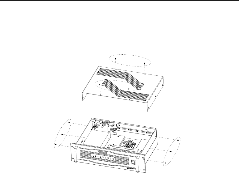
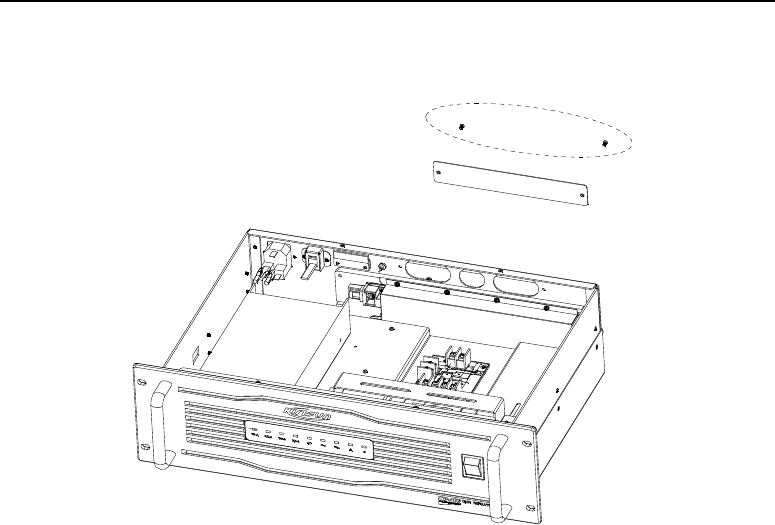
5 Installation Guide (refit guide)
Duplexer Installation
(1)Disassembly:As the figure below, take off the 4 screws and 6 screws of two sides of the top
cover, and then slightly open the top cover.
TR850 DMR Repeater Instruction Manual
19
(2)Take off the two screws of duplexer baffle, remove the duplexer.
TR850 DMR Repeater Instruction Manual
20
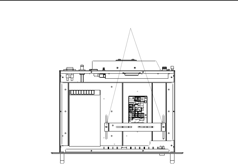
(3)Slightly loosen the two screws of fixed duplexer bracket on installed clapboard to the bracket,
and do not too loosen. Refer to following figure.
TR850 DMR Repeater Instruction Manual
21
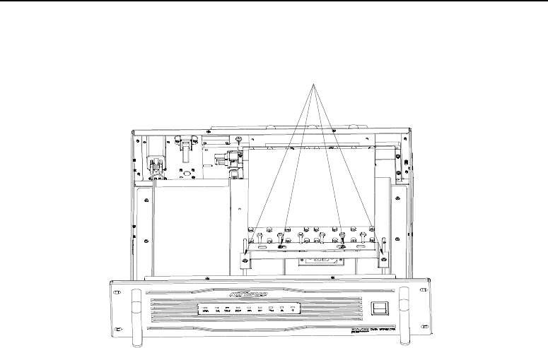
(4)Fixed the duplexer tail screws to the duplexer bracket. Push the duplexer to the end three
duplexer connection holes until the duplexer is locked. Then fasten the duplexer bracket and
install screw. Refer to following figure.

TR850 DMR Repeater Instruction Manual
22
6 Frequently Asked Questions (FAQ)
Can’t connect to the PC programming software
The IP of repeater input is error in the programming software. Or the user forgets the IP of
repeater.
Can’t transfer
Please confirm the frequency and the working mode of the radio is the same with the repeater.
TR850 DMR Repeater Instruction Manual
23
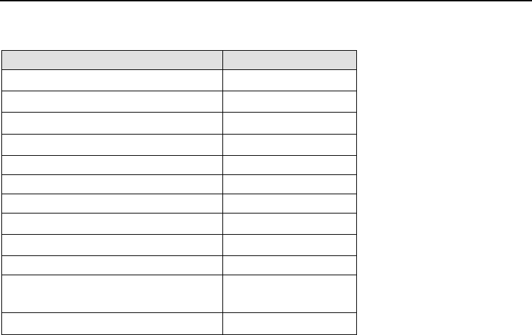
7 Recommend Duplexer Parameters
Model
SGQ-450 A / D
Duplexer’Frequency Range(MHz)
380~520
Bandwidth(KHz)
±400
Frequency Spacing(MHz)
10
Insertion Loss(dB)
<1.0
Isolation (dB)
>80
Suppression(dB)
>80
V.S.W.R
<1.3
NormaI lmpedance(Ω)
50
Max Power Input(W)
30 / 50
Standard Termination
N/BNC
Dimensions(mm)
223×154×31.5
223×191×39
Weight(KG)
1.2 / 2.0

between the antenna radiator& your body.
TR850 DMR Repeater Instruction Manual
24
FCC Statement:
Any Changes or modifications not expressly approved by the party responsible for compliance
could void the user’s authority to operate the equipment.
This device complies with part 15 of the FCC Rules. Operation is subject to the following two
conditions: (1) This device may not cause harmful interference, and (2) this device must accept
any interference received, including interference that may cause undesired operation.
FCC Radiation Exposure Statement:
This equipment complies with FCC radiation exposure limits set forth for an controlled
environment. This equipment should be installed and operated with minimum distance 1.0m
This transmitter must not be co-located or operating in
conjunction with any other antenna or transmitter.
IC RSS warning
This device complies with Industry Canada licence-exempt RSS standard (s). Operation is subject
to the following two conditions: (1) this device may not cause interference, and (2) this device
must accept any interference,including interference that may cause undesired operation of the
device.
Le présent appareil est conforme aux CNR d'Industrie Canada applicables aux appareils radio
exempts de licence.

TR850 DMR Repeater Instruction Manual
25
L'exploitation est autorisée aux deux conditions suivantes:
(1) l'appareil ne doit pas produire de brouillage, et
(2) l'utilisateur de l'appareil doit accepter tout brouillage radioélectrique subi, même si le brouillage
est susceptible d'en compromettre le fonctionnement.
Under Industry Canada regulations, this radio transmitter may only operate using an antenna of a
type and maximum (or lesser) gain approved for the transmitter by Industry Canada. To reduce
potential radio interference to other users, the antenna type and its gain should be so chosen that,
the equivalent isotropically radiated power (e.i.r.p.) is not more than that necessary for successful
communication.
Conformément à la réglementation d'Industrie Canada, le présent émetteur radio peut fonctionner
avec une antenne d'un type et d'un gain maximal (ou inférieur) approuvé pour l'émetteur par
Industrie Canada. Dans le but de réduire les risques de brouillage radioélectrique à l'intention des
autres utilisateurs, il faut choisir le type d'antenne et son gain de sorte que la puissance isotrope
rayonnée équivalente (p.i.r.e.) ne dépasse pas l'intensité nécessaire à l'établissement d'une
communication satisfaisante.
IC Radiation Exposure Statement:
This equipment complies with IC RF radiation exposure limits set forth for an controlled

TR850 DMR Repeater Instruction Manual
26
environment. This transmitter must not be co-located or operating in conjunction with any other
antenna or transmitter.This equipment should be installed and operated with minimum distance
1.0m between the radiator & your body.
IC exposition aux radiations:
Cet équipement est conforme avec IC les limites d'exposition aux rayonnements définies pour
contrôlé environnement. Cet émetteur ne doit pas être co-localisés ou fonctionner en conjonction
avec une autre antenne ou émetteur.Cet équipement doit être installé et utilisé avec un minimum
de 1,0 m de distance entre le radiateur et votre corps.