Kiwi Technology TLM922S LoRa Module User Manual
Kiwi Technology Inc. LoRa Module Users Manual
Users Manual
t
aifatech Confidential Documentation
TLM922S-P01A
Product Specification
V.2.0.0

k
iwitec Confidential Documentation
History
Date Version Revision Description Writer
2016/6/3 V. 0.9 First release LiuKen
2016/6/28
V.1.0 LiuKen
2016/7/4 V1.0.1 Correct Typo LiuKen
2016/8/3 V1.0.2 Support baudrate, echo and, duty cycle. LiuKen
2016/9/05
V1.0.3 LiuKen
2016/9/08
V1.0.4 Fix Typo LiuKen, Terry
2016/9/27 V1.0.5 Add note for firmware upgrade and M0 Jesse
2016/10/04
V1.0.6 Support deep sleep LiuKen
2016/11/01
V1.1.0 Support channel plan setting, remove set_band/get_band LiuKen, Terry
2016/11/14
V1.1.1 Update pinout and support wakeup from wakeup pin LiuKen, Terry
2017/1/23 V1.1.2 Remove mod dio command, add battery setting command Terry
2017/4/25 V1.1.3 Add UART interface timing diagram Cliff
2017/7/12 V1.1.4 Update "General Characteristics" Cliff
2017/9/11 V2.0.0 Update to V2.0.0 and ADB922. LiuKen

k
iwitec Confidential Documentation i
Table of Contents
1.
Introduction ........................................................................................................................................ 1
1.1.
Hardware Characteristics ........................................................................................................... 2
1.1.1.
Pin Configuration ........................................................................................................................ 2
1.1.2.
PCB Description and Dimension ................................................................................................. 3
1.1.3.
UART Interface ........................................................................................................................... 4
1.1.4.
I2C and SPI Interfaces ................................................................................................................. 4
1.1.5.
Reference Schematic .................................................................................................................. 5
1.2.
Software Characteristics ............................................................................................................. 6
1.3.
TLM922S-P01A EVB .................................................................................................................... 7
1.4.
TLM922S-P01A Arduino Shield ................................................................................................... 9
2.
Command Reference ..........................................................................................................................11
2.1.
Command Format .....................................................................................................................11
2.2.
Module Commands ...................................................................................................................11
2.2.1.
mod factory_reset .................................................................................................................... 11
2.2.2.
mod get_ver ............................................................................................................................. 11
2.2.3.
mod get_hw_deveui ................................................................................................................. 11
2.2.4.
mod get_hw_model ................................................................................................................. 11
2.2.5.
mod sleep <Deep> <INTwake> <Period> ................................................................................. 12
2.2.6.
mod set_baudrate <Baudrate> ................................................................................................ 12
2.2.7.
mod set_echo <Status> ............................................................................................................ 12
2.2.8.
mod reset ................................................................................................................................. 12
2.2.9.
mod save .................................................................................................................................. 12
2.3.
LoRaWAN Commands ...............................................................................................................13
2.3.1.
lorawan join <Mode> ............................................................................................................... 15
2.3.2.
lorawan get_join_status ........................................................................................................... 15
2.3.3.
lorawan tx <Type> <PortNum> <Data> .................................................................................... 16
2.3.4.
lorawan set_deveui <DevEUI> ................................................................................................. 16
2.3.5.
lorawan set_appeui <AppEUI> ................................................................................................. 16
2.3.6.
lorawan set_appkey <AppKey> ................................................................................................ 17
2.3.7.
lorawan set_devaddr <DevAddr> ............................................................................................. 17
2.3.8.
lorawan set_nwkskey <NwkSessionKey> ................................................................................. 17
2.3.9.
lorawan set_appskey <AppSessionKey> .................................................................................. 17
2.3.10.
lorawan set_pwr <PowerIndex> .............................................................................................. 18

k
iwitec Confidential Documentation ii
2.3.11.
lorawan set_dr <DataRate> ...................................................................................................... 18
2.3.12.
lorawan set_adr <State> .......................................................................................................... 18
2.3.13.
lorawan set_txretry <RetryCount> ........................................................................................... 18
2.3.14.
lorawan set_rxdelay1 <Delay> ................................................................................................. 18
2.3.15.
lorawan set_rx2 <DataRate> <Frequency> .............................................................................. 19
2.3.16.
lorawan set_ch_freq <ChannelId> <Frequency>...................................................................... 19
2.3.17.
lorawan set_ch_dr_range <ChannelId> <MinDR> <MaxDR> ................................................... 19
2.3.18.
lorawan set_ch_status <ChannelId> <Status> ......................................................................... 19
2.3.19.
lorawan set_linkchk .................................................................................................................. 20
2.3.20.
lorawan set_dc_ctl <Status> .................................................................................................... 20
2.3.21.
lorawan set_dc_band <BandID> <MinFreq> <MaxFreq> <DutyCycle> .................................... 20
2.3.22.
lorawan set_join_ch <ChannelID> <Status> ............................................................................. 20
2.3.23.
lorawan set_upcnt <UplinkCounter> ....................................................................................... 21
2.3.24.
lorawan set_downcnt <DownlinkCounter>.............................................................................. 21
2.3.25.
lorawan set_class <Class> ........................................................................................................ 21
2.3.26.
lorawan set_pwr_table <Index> <Power> ............................................................................... 21
2.3.27.
lorawan set_max_payload_table <DRIndex> <MaxPayload> .................................................. 21
2.3.28.
lorawan set_dl_freq <ChannelID> <Frequency> ...................................................................... 22
2.3.29.
lorawan update_payload_table <DwellTime> ......................................................................... 22
2.3.30.
lorawan set_battery <BatteryLevel> ........................................................................................ 22
2.3.31.
lorawan set_multicast_key <Index> <Address> <NwkSkey> <AppSkey>................................. 22
2.3.32.
lorawan set_uplink_dwell_table <Index> <MinFreq> <MaxFreq> <UplinkDwell> (AS923
Only) 23
2.3.33.
lorawan set_lbt_retry <RetryCount> ....................................................................................... 23
2.3.34.
lorawan save ............................................................................................................................. 23
2.3.35.
lorawan get_devaddr ............................................................................................................... 23
2.3.36.
lorawan get_deveui .................................................................................................................. 23
2.3.37.
lorawan get_appeui .................................................................................................................. 24
2.3.38.
lorawan get_nwkskey ............................................................................................................... 24
2.3.39.
lorawan get_appskey ............................................................................................................... 24
2.3.40.
lorawan get_appkey ................................................................................................................. 24
2.3.41.
lorawan get_dr ......................................................................................................................... 24

k
iwitec Confidential Documentation iii
2.3.42.
lorawan get_pwr ...................................................................................................................... 24
2.3.43.
lorawan get_adr ....................................................................................................................... 24
2.3.44.
lorawan get_txretry .................................................................................................................. 25
2.3.45.
lorawan get_rxdelay ................................................................................................................. 25
2.3.46.
lorawan get_rx2........................................................................................................................ 25
2.3.47.
lorawan get_ch_para <ChannelId> .......................................................................................... 25
2.3.48.
lorawan get_ch_status <ChannelId> ........................................................................................ 25
2.3.49.
lorawan get_dc_ctl ................................................................................................................... 26
2.3.50.
lorawan get_dc_band <BandID> .............................................................................................. 26
2.3.51.
lorawan get_join_ch ................................................................................................................. 27
2.3.52.
lorawan get_upcnt ................................................................................................................... 27
2.3.53.
lorawan get_downcnt .............................................................................................................. 27
2.3.54.
lorawan get_class ..................................................................................................................... 27
2.3.55.
lorawan get_pwr_table <Index> .............................................................................................. 27
2.3.56.
lorawan get_max_payload_table <DRIndex> .......................................................................... 28
2.3.57.
lorawan get_dl_freq <ChannelID> ........................................................................................... 28
2.3.58.
lorawan get_battery ................................................................................................................. 28
2.3.59.
lorawan get_multicast_key <Index> ........................................................................................ 29
2.3.60.
lorawan get_lbt_retry .............................................................................................................. 29
2.4.
P2P Commands .........................................................................................................................30
2.4.1.
p2p rx <RxWindowTime> ......................................................................................................... 30
2.4.2.
p2p tx <Data> ........................................................................................................................... 30
2.4.3.
p2p set_freq <Frequency> ....................................................................................................... 30
2.4.4.
p2p set_pwr <Power> .............................................................................................................. 31
2.4.5.
p2p set_sf <SpreadingFacotr> .................................................................................................. 31
2.4.6.
p2p set_bw <BandWidth> ........................................................................................................ 31
2.4.7.
p2p set_cr <CodingRate> ......................................................................................................... 31
2.4.8.
p2p set_prlen <PreambleLength> ............................................................................................ 31
2.4.9.
p2p set_crc <State> .................................................................................................................. 32
2.4.10.
p2p set_iqi <Invert>.................................................................................................................. 32
2.4.11.
p2p set_sync <SyncWord> ....................................................................................................... 32
2.4.12.
p2p save .................................................................................................................................... 32

k
iwitec Confidential Documentation iv
2.4.13.
p2p get_freq ............................................................................................................................. 32
2.4.14.
p2p get_pwr ............................................................................................................................. 33
2.4.15.
p2p get_sf ................................................................................................................................. 33
2.4.16.
p2p get_bw ............................................................................................................................... 33
2.4.17.
p2p get_prlen ........................................................................................................................... 33
2.4.18.
p2p get_crc ............................................................................................................................... 33
2.4.19.
p2p get_iqi ................................................................................................................................ 34
2.4.20.
p2p get_cr ................................................................................................................................. 34
2.4.21.
p2p get_sync ............................................................................................................................ 34
3.
Example .............................................................................................................................................35
3.1.
LoRaWAN .................................................................................................................................35
3.1.1.
ABP and Uplink ......................................................................................................................... 35
3.1.2.
OTA and Uplink ......................................................................................................................... 36
3.1.3.
Confirmed Uplink and Downlink .............................................................................................. 36
3.2.
P2P ...........................................................................................................................................37
4.
Firmware Upgrade ..............................................................................................................................38

k
iwitec Confidential Documentation 1
1. Introduction
TLM922S-P01A is a small size and ultra-low power UHF wireless module based on LoRa technology of Sem-
tech. TLM922S-P01A module integrates a 32bit MCU, Cypress S6E1C32, and a single-chip radio transmitter,
Semtech SX1272, designed for high performance at very low-power and low-voltage operation in
cost-effective wireless systems. All filters are integrated, thus removing the need for costly external SAW and
IF filters. The device is mainly intended for the ISM (Industrial, Scientific, and Medical) frequency bands at
902-928 MHz. The module integrated many RF functions and PA to make the maximum output power up to
+20dBm and signal coverage can reach up 10km.
General Characteristics
PARAMETER TYPICAL CONDITION/NOTE
Operating supply Voltage DC 2.2 ~ 3.6V
Frequency 902MHz~928MHz Programmable
Frequency Accuracy ±10KHz
Modulation LoRa
Transmit Power +2 ~ +20dBm Output power programmable
Receive Sensitivity Up to -138dBm
TX Current Consumption < 140mA Po= +20dBm
Standby State Current Consumption
< 6.2mA DC 3.3V
Sleep State current consumption
< 1uA (w/o RTC)
< 3uA (w / RTC) DC 3.3V
Data Rate 0.244 18.2Kbps(LoRa) Programmable
Spurious Emissions and Harmonics < -30dBm TX power +20dBm
Communication Distance 10Km 0.244Kbps Baud data rata, BW=125K
Output power = +20dBm.
Antenna Impedance 50ohm
Operating Temperature -40°C ~ +85 °C
Storage Temperature Range -40°C ~ +90°C
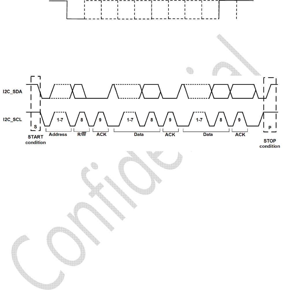
Dimension 23.5mm×23.2mm×3.1mm
LoRaWAN Certification LoRaWAN 1.0.2
Certification NCC, TELEC
Test operating conditions Ta=25°C VCC=3.3V if nothing else stated.
Note
1. The module transmission data rate will affect transmission distance, the higher the data rate, the closer
the distance, and the lower the receiving sensitivity.
2. The supply voltage to the module will affect TX power, in the operating supply voltage range, the lower
the voltage to get the lower the TX power.
3. The antenna will strongly affect the communication distance, please select matched antenna and connect
it correctly.
4. The module mount will affect the communication distance.

k
iwitec Confidential Documentation 2
1.1. Hardware Characteristics
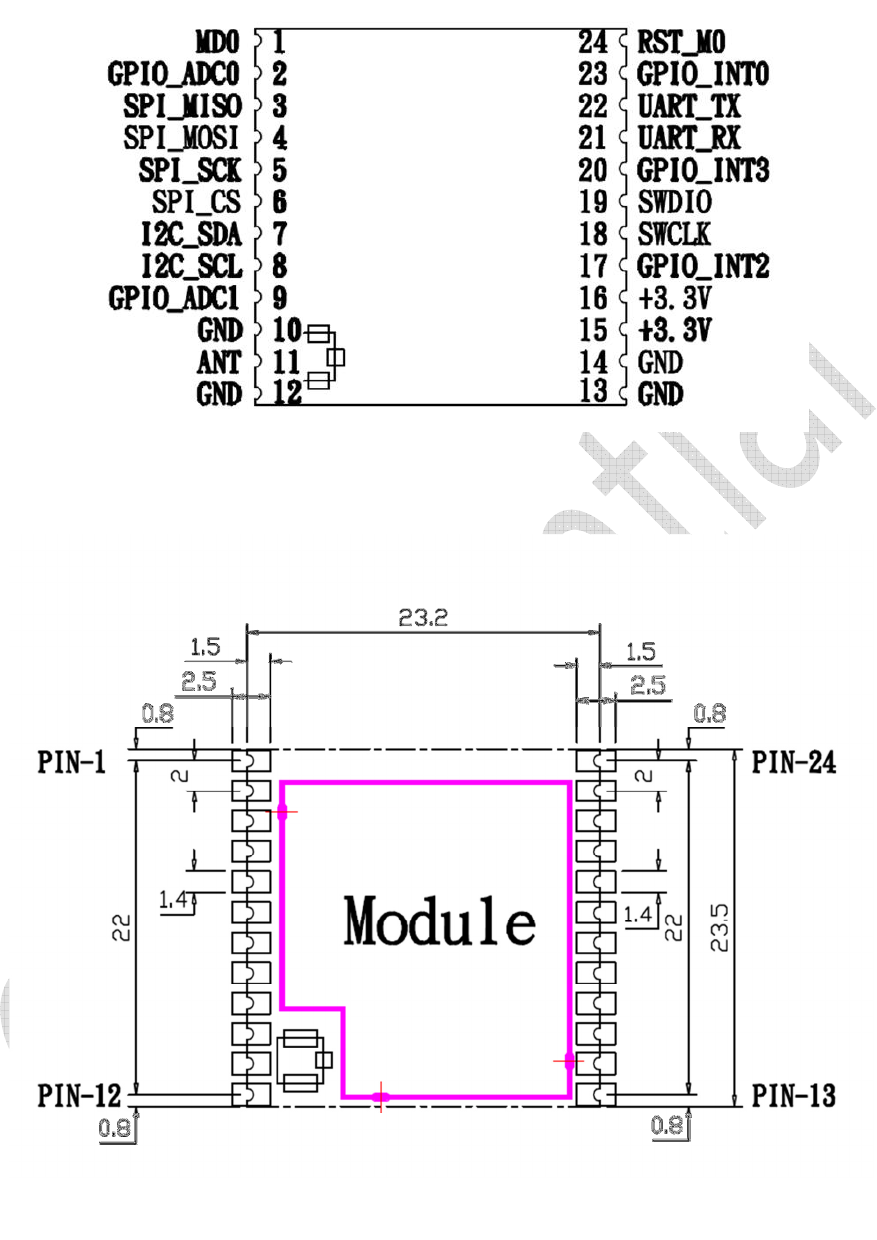
1.1.1. Pin Configuration
PIN
PIN NAME Description
1 MD0
During normal operation, input MD0="L".
During serial programming to Flash memory, input MD0="H".*
* this is only for Cypress programming tool
2 GPIO_ADC0 A/D converter analog input pin and general-purpose I/O
3 SPI_MISO SPI interface
4 SPI_MOSI SPI interface
5 SPI_SCK SPI interface
6 SPI_CS SPI interface
7 I2C_SDA I2C interface
8 I2C_SCL I2C interface
9 GPIO_ADC1 A/D converter analog input pin and general-purpose I/O
10
GND RF ground
11
ANT RF output signal
12
GND RF ground
13
GND System ground
14
GND System ground
15
+3.3V Power source
16
+3.3V Power source
17
GPIO_INT2 External interrupt request and general-purpose I/O
18
SWCLK Serial wire debug interface clock input pin
19
SWDIO Serial wire debug interface data input output pin
20
GPIO_INT3 External interrupt request and general-purpose I/O
21
UART_RX UART interface
22
UART_TX UART interface
23
GPIO_INT0 External interrupt request and general-purpose I/O
24
RST_M0 External Reset Input pin, active low.
Note:
1. The module power supply voltage range is DC 2.2 3.6V, above DC 3.6V, the module will damage. It is
recommended work at DC 3.3 V.
2. The module interface uses half circle pad to soldering on the system PCB board, the GND must soldering
to the system digital GND reliably, or use connector to connect main board.
3. The antenna must the get to the module’s ANT pin as close as possible.
4. The module’s pin GPIO_ADC and GPIO_INT are general digital I/O ports, they also can be programmable
to A/D converter analog input pin and external interrupt pin.
k
iwitec Confidential Documentation 3
1.1.2. PCB Description and Dimension
k
iwitec Confidential Documentation 4
1.1.3. UART Interface
TLM922S-P01A module provides a UART interface to use LoRa
TM
and LoRaWAN
TM
commands that supports in
TLM922S-P01A module. The baud rate of UART interface is fixed at 115200-8N1 on PIN21 and PIN22 in de-
fault. Following figure illustrates the timing of UART interface. For details please refer to document of Cypress
MCU "S6E1C3 Series".
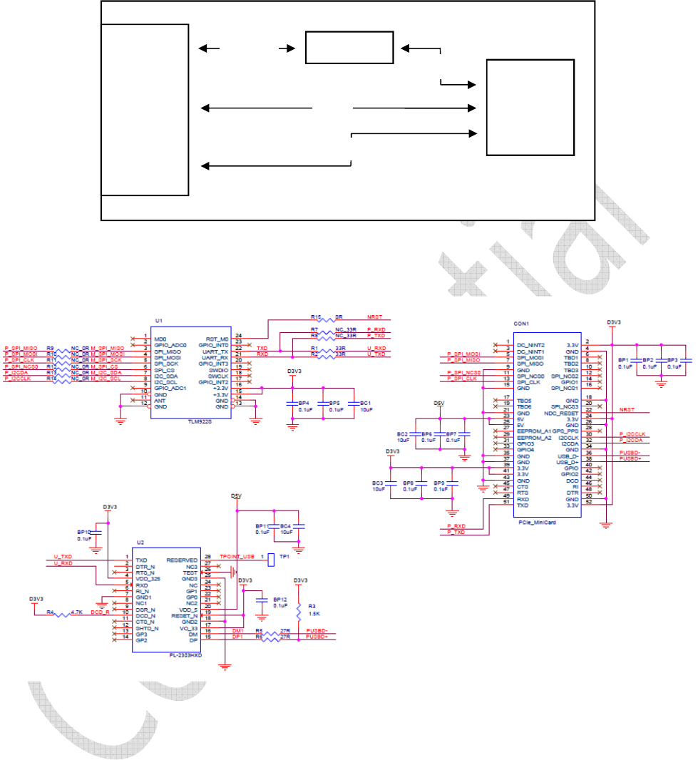
1.1.4. I2C and SPI Interfaces
The I2C and SPI interfaces of TLM922S-P01A module are used to access external devices, like sensors. Below
timing is general timing diagram of I2C. Detail information please refer to document of Cypress MCU "S6E1C3
Series".
Bit 2
Bit 3
Bit 4
Bit 5
Bit 6
Bit 7
Bit 8
Logic 1
Logic 0
Idle
Start
bit
Stop
bit
Idle
k
iwitec Confidential Documentation 5
1.1.5. Reference Schematic
The schematic is an example of interface conversion from UART to USB with PCIe connector. Interfaces of SPI
and I2C of TLM922S-P01A are also connected PCIe connector.
CON1
-
PCIe
Bit 1
PL2303HXD
TLM922S
-P01A
UART
SPI
D+/D
-
I2C
k
iwitec Confidential Documentation 6
1.2. Software Characteristics
TLM922S-P01A module provides a command interface to use LoRa
TM
and LoRaWAN
TM
communication
through UART interface. The LoRaWAN
TM
protocol has been certified by LoRa Alliacne.
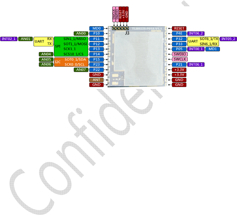
TLM922S-P01A can be controlled by connecting PIN 21 and PIN 22 of TLM922S-P01A, which are equivalent to
P32 and P33 shown in Figure 1, to UART interface of PC or other MCU. Then, the control commands can be
sent from PC or other MCU to TLM922S-P01A. The baud rate of TLM922S UART is fixed at 115200-8N1. Figure
1 also illustrates that each pin is multifunction, and can be also configured and controlled through command
interface.
Figure 1-1 TLM922S-P01A Pinout
k
iwitec Confidential Documentation 7
1.3. TLM922S-P01A EVB
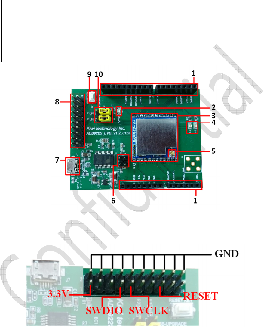
For faster development, kiwitec also provides an EVB for TLM922S-P01A. The EVB equips with a USB-UART
bridge and can be powered by USB. Furthermore, an SMA antenna connector is also provided for easily in-
stalling antenna. Figure 1-2 and following table depict this EVB and its connector.
1. Arudino Interface (J1, J3, J4, J5)
2. Power LED (D2)
3. TLM922S-P01A
4. UART TX/RX LED (D4, D5)
5. Antenna Connector
6. Serial Programming Jumper (J6, J11)
7. USB Device Connector (J7)
8. J-Link/SWD Connector (J2)
9. Reset Button (SW1)
10. USB Serial Mode Select (J9, J10)
Figure 1-2 TLM922S-P01A EVB
J2 is a J-Link port connected to module’s SWD for debug purpose. Following figure is function of each pin.
k
iwitec Confidential Documentation 8
To quickly start to use TLM922S-P01A EVB, the first step is using USB cable to connect EVB to PC via J7. Next
step is checking whether the USB bridge driver is properly installed on your PC. If PC cannot recognize the
device, the driver can be downloaded from Prolific’s website
1
(the model name of USB bridge model is
PL2303HXD). After successful installation of USB driver, you can use any terminal program to connect to EVB
and the default setting is 115200-8N1. Then, the command interface can be used through the terminal pro-
gram.
Figure 1-3 Connection with PC
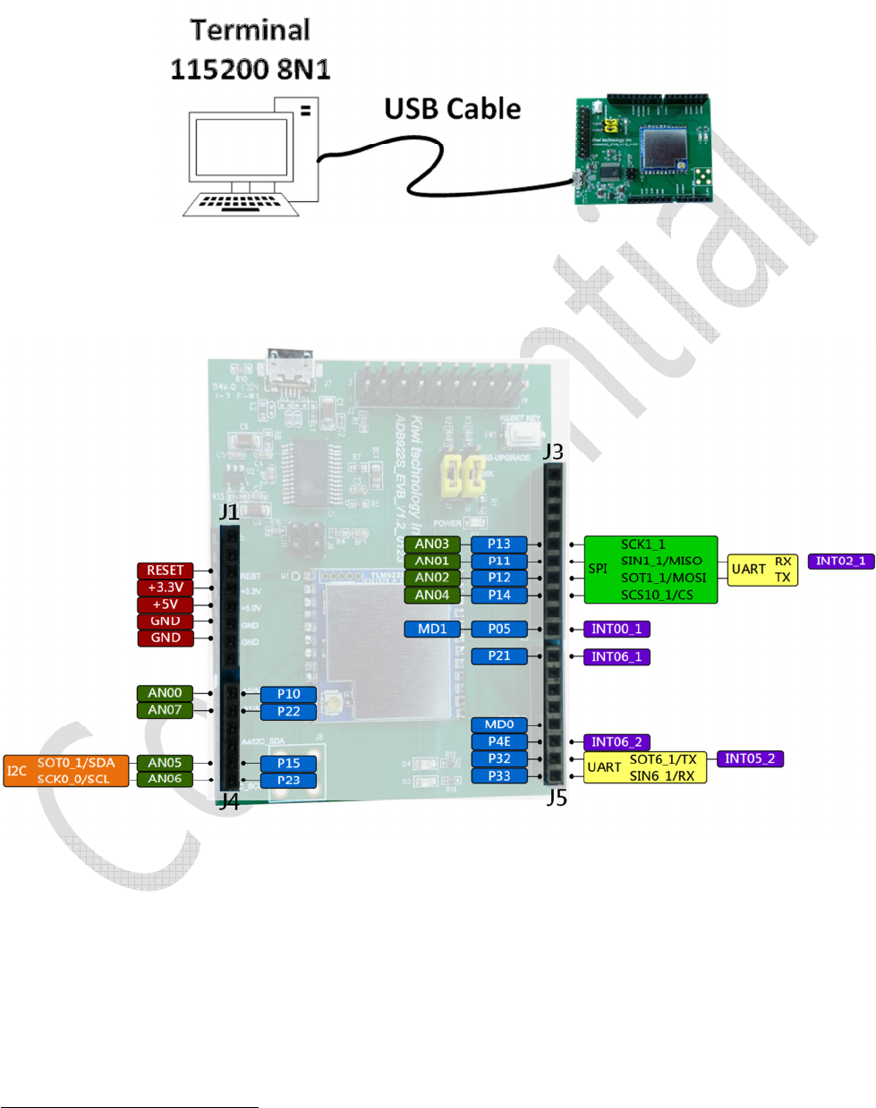
As stated at 1.2, TLM922S-P01A provides multifunction pins. Theses pins are also exported on EVB as Figure
1-4 shown.
Figure 1-4 TLM922S-P01A EVB Pinout
1
http://www.prolific.com.tw/US/ShowProduct.aspx?p_id=225&pcid=41
k
iwitec Confidential Documentation 9
1.4. TLM922S-P01A Arduino Shield
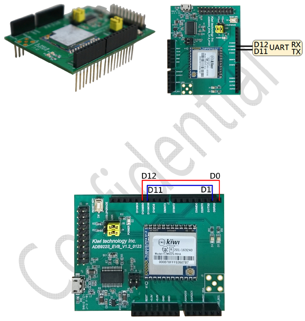
There is also another type of development board of TLM922S-P01A, called ADB922. This is an Arduino Shield
which has Arduino-compatible pin header. Instead of the pin header, the hardware component and schematic
is identical to TLM922S-P01A EVB. However, to cooperate with Arduino, the default UART pin and configura-
tion is also different.
Figure 1-5 ADB922
Figure 1-6 Pinout of ADB922
Figure 1-6 shows default UART pin of ADB922S and the default UART setting is 9600-8N1.
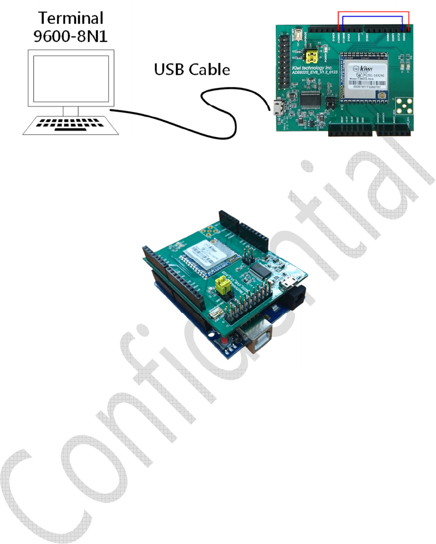
To quickly start to use ADB922S Arduino shield, the first step is using USB cable to connect shield to PC via
micro-USB connector. Then wire the D0 to D12 and D1 to D11, as Figure 1-7 shown.
Figure 1-7 Wire Connection for Quick Start
k
iwitec Confidential Documentation 10
Next step is checking whether the USB bridge driver is properly installed on your PC. After successful installa-
tion of USB driver, you can use any terminal program to connect to shield and the default setting is 9600-8N1.
Then, the command interface can be used through the terminal program.
Figure 1-8 Connection with PC
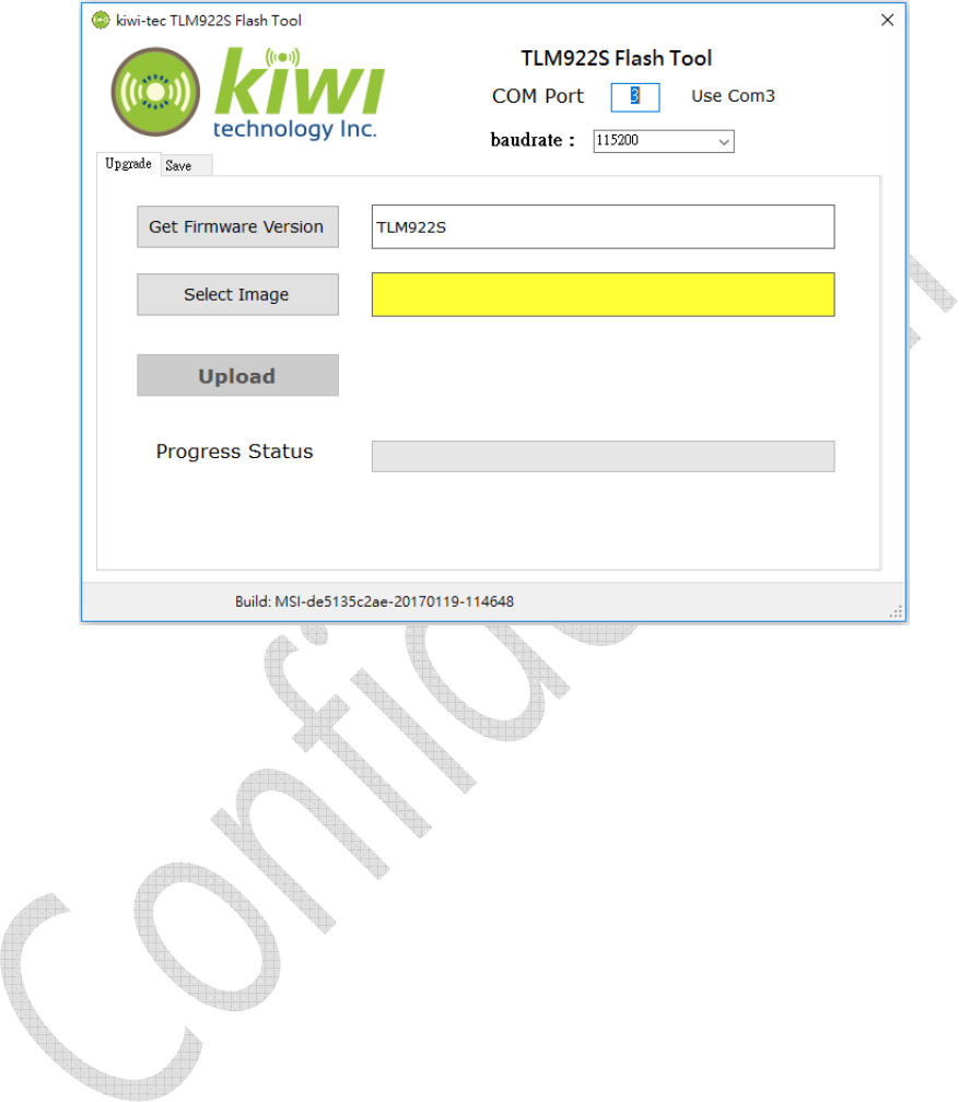
The usual use of this shield is mounted on Arduino, as Figure 1-9 shown.
Figure 1-9 Mount on Arduino Uno

k
iwitec Confidential Documentation 11
2. Command Reference
2.1. Command Format
TLM922S-P01A’s commands can be categorized into 3 types: module command, LoRaWAN
TM
command, and
P2P command. Module commands are control commands not related to radio transmission. LoRaWAN
TM
commands are used to utilize LoRaWAN
TM
protocol. P2P commands can be used to send and receive raw
packet.
The command interface is readable ASCII string. TLM922S-P01A starts to accept command after outputting a
'>' character, and the response string from TLM922S-P01A starts with two '>' characters. TLM922S-P01A will
output message"> TLM922S-P01A <" when boot module. The first line of following example is a module
command, and the second line is the response from TLM922S-P01A.
Example:
> mod get_ver
>> V1.3.1-Jan 20 2017-11:41:14
Note that the input command must end with a CR.
2.2. Module Commands
2.2.1. mod factory_reset
Response: Ok.
All LoRaWAN, radio and module configuration parameters will be set to default value.
Example:
> mod factory_reset
>> Ok
2.2.2. mod get_ver
Response: a string representing firmware version, bulid date and bulid time.
Get current firmware version.
Example:
> mod get_ver
>> V1.3.1-Jan 20 2017-11:41:14
2.2.3. mod get_hw_deveui
Response: a string representing hardware EUI in hexadecimal.
Get hardware EUI.
Example:
> mod get_hw_deveui
>> 000b78ffff000000
2.2.4. mod get_hw_model
Response: a string representing hardware model and UUID.
Get hardware model name.
Example:
> mod get_hw_model
>> TLM922S-P01A-117012000001

k
iwitec Confidential Documentation 12
2.2.5. mod sleep <Deep> <INTwake> <Period>
<Period>: a string representing sleep time in second, can be from 0 to 65535 (0 means infinite sleep,
wakeup by P21).
<INTWake>: enable wakeup by P21 or not, can be 0 (disable) or 1 (enable).
<Deep>: deep sleep mode or not, 0 is normal sleep mode, and 1 is deep sleep mode.
Response: Ok, if <Period> and <Deep> string is valid
Invalid, if <Period> and <Deep> string is not valid.
Module will be in sleep mode for <Period> seconds.
If <INTWake> is enable, module also returns from sleep while P21 is triggered. To use P21 as a wakeup
pin in sleep, P21 needs to set LOW before entering sleep. Once P21 changes from LOW to HIGH, module
would return from sleep.
Example:
> mod sleep 0 0 10
>> Ok
2.2.6. mod set_baudrate <Baudrate>
<Baudrate>: a string representing UART barudrate used for command interface, can be from 9600,
19200, 57600, 115200.
Response: Ok, if <Baudrate> string is valid
Invalid, if <Baudrate> string is not valid.
Module will use <Baudrarte> for command interface.
Example:
> mod set_baudrate 9600
>> Ok
2.2.7. mod set_echo <Status>
<Status>: a string representing echo status, can be on or off.
Response: Ok, if <Status> string is valid.
Invalid, if <Status> string is not valid.
Enable or disable UART echo mode.
Example:
> mod set_echo on
>> Ok
2.2.8. mod reset
Response: no response.
Reset TLM922S-P01A.
Example:
> mod reset
2.2.9. mod save
Response: Ok
Save module configuration (baudrate and echo status) to flash.
Example:
> mod save
>> Ok

k
iwitec Confidential Documentation 13
2.3. LoRaWAN Commands
TLM922S-P01A Command Interface has several built-in configuration tables that can be used to customize for
fulfilling different channel requirements. Before diving into these tables, data rate settings must be intro-
duced first. Table 2-1 shows TLM922S-P01A Command Interface’s data rate settings which are originally de-
fined in LoRaWAN standard. The DR7, using FSK, is not supported by TLM922S-P01A. Thus the DR number can
be used in TLM922S-P01A Command Interface is from 0 to 6.
Table 2-1 Data Rate Settings
DR Setting
Configuration Indicative bit rate (bit/s)
Supported byTLM922S-P01A
DR0 SF12 BW125KHz
250 Yes
DR1 SF11 BW125KHz
440 Yes
DR2 SF10 BW125KHz
980 Yes
DR3 SF9 BW125KHz
1760 Yes
DR4 SF8 BW125KHz
3125 Yes
DR5 SF7 BW125KHz
5470 Yes
DR6 SF7 BW250KHz
11000 Yes
DR7 FSK 50bps 50000 No
There is two different data rate settings which are only used at US915 and AU915 separately, as Table 2-2 and
Table 2-3 shown.
Table
2
-
2
Data Setting for US915 and US915_HYBRID
DR Setting
Configuration
Indicative bit rate
(bit/s)
DR0 SF10 125KHz 980
DR1 SF9 125KHz 1760
DR2 SF8 125KHz 3125
DR3 SF7 125KHz 5470
DR4 SF8 500KHz 12500
DR5~DR7 NA NA
DR8 SF12 500KHz 980
DR9 SF11 500KHz 1760
DR10 SF10 500KHz 3900
DR11 SF9 500KHz 7000
DR12 SF8 500KHz 12500
DR13 SF7 500KHz 21900
DR14~DR15
NA NA
Table
2
-
3
Data Setting for AU915
DR Setting
Configuration
Indicative bit rate
(bit/s)
DR0 SF10 125KHz 250
DR1 SF12 125KHz 440
DR2 SF11 125KHz 980
DR3 SF10
BW125KHz
1760
DR4 SF9 125KHz 3125
DR5 SF8 125KHz 5470
DR6 SF7 125KHz 12500
DR7 NA NA
DR8 SF12 500KHz 980
DR9 SF11 500KHz 1760
DR10 SF10 500KHz 3900
DR11 SF9 500KHz 7000
DR12 SF8 500KHz 12500
DR13 SF7 500KHz 21900
DR14~DR15
NA NA

k
iwitec Confidential Documentation 14
The first configurable table is frequency table that sets frequencies used by TLM922S-P01A. There are 16
channels allowed to set. There are plenty of settings can be set for each channel as shown at Table 2-4. The
Frequency of each channel can be set by set_ch_freq command. Max. DR and Min. DR are the maximum and
minimum data rate supported in this channel and can be set by set_ch_dr_range command. Enable indicates
whether this channel is enabled or disabled and set_ch_status command is used to enable or disable the
channel. Join Channel uses to determine does this channel can be used in OTA and set_join_ch is used to set
this. Band ID is which band in duty cycle table belongs to. All settings in frequency table except Band ID are
can be configured by commands. Band ID is automatically determined from duty cycle table.
Table 2-4 Frequency Table
Index Frequency Min. DR Max. DR Enable Join Channel
Band ID
0
1
2
…
15
Duty cycle table, Table 2-5, defines transmission duty cycle for different frequency bands. set_dc_band
command is used to define duty cycle of each frequency band. TLM922S-P01A allows to configure 16 differ-
ent bands.
Table 2-5 Duty Cycle Table
Band ID Min Frequency Max Frequency Duty Cycle
0
1
2
...
15
Table 2-6 shows the TX power table used in TLM922S-P01A. The TX power index is used within LoRaWAN
protocol for referring to different transmission power. TLM922S-P01A only supports 6 different TX power set-
tings. set_pwr_table is the command used to change transmission power. Table 2-7 is the maximum payload
size for each DR which defines at Table 2-1. To change maximum payload size uses set_max_payload_table
commands.
Table
2
-
6
TX Power Table
Index TX Power (dBm)
0
1
2
3
4
5
Table
2
-
7
Max. Payload
Size
Table
Index DR Max. Payload Size (bytes)
0 DR0
1 DR1
2 DR2
3 DR3
4 DR4
5 DR5
6 DR6

k
iwitec Confidential Documentation 15
Table 2-8 is a downlink frequency table which is used to implement DlChannel in LoRaWAN 1.0.2. This table
defines downlink frequencies for each uplink channel defined at Table 2-4. TLM922S-P01A also provide a
command, set_dl_freq, to configure downlink frequency table.
Table 2-8 Downlink Frequency Table
Channel Index Downlink Frequency
0
1
2
…
15
The last table is only use at AS923 channel plan, called uplink dwell table. Each row of table is used to enable
uplink dwell of specified frequency range (Min. Frequency ~ Max. Frequency). TLM922S-P01A supports up to
16 different frequency range of uplink dwell setting. This table can be accessed by set_uplink_dwell_table
and get_uplink_dwell_table.
Table 2-9 Uplink Dwell Table (AS923 Only)
Index Min. Frequency Max. Frequency Uplink Dwell
0
1
2
…
15
2.3.1. lorawan join <Mode>
<Mode>: a string representing join mode of LoRaWAN, can be otaa (over-the-air activation) or abp (ac-
tivation by personalization).
Response: there is two responses after entering this command. The first response, used to indicate that
whether command is valid or parameters is set appropriately, will be received after entering command.
The second response will be received after join procedure.
First response: Ok, if <Mode> string is valid.
Invalid, if <Mode> string is not valid.
keys_not_init, keys are not configured.
no_free_ch, no channels are available.
busy, internal state is busy.
Second response: accepted, successfully join LoRaWAN.
unsuccess, join procedure is unsuccessful.
Star join procedure of LoRaWAN.
Example:
> lorawan join abp
>> Ok
>> accepted
2.3.2. lorawan get_join_status
Response: a string representing whether module is joined successfully.
Returned string can be: joined, unjoined.
Get join status of LoRaWAN.
Example:
> lorawan get_join_status
>> joined

k
iwitec Confidential Documentation 16
2.3.3. lorawan tx <Type> <PortNum> <Data>
<Type>: a string representing type of transmitting message, can be cnf (confirmed) or ucnf (uncon-
firmed).
<PortNum>: a decimal string representing port number used for transmission, can be from 1 to 233.
<Data>: a hexadecimal string representing data to be transmitted.
Response: there is two responses after entering this command. The first response will be received after
entering command. The second response will be received after transmission.
First response: Ok, if <Type>, <PortNum> and <Data> strings are valid.
Invalid, if <Type>, <PortNum> and <Data> strings are not valid.
not_joined, module is not joined LoRaWAN.
no_free_ch, no channels are available.
busy, internal state is busy.
invalid_data_length, data length is greater than allowed data length.
Second response: tx_ok, successfully transmit data.
rx <portnum> <data>, there is downlink data.
<portnum> - a decimal string representing receiving port
<data> - a hexadecimal string representing received data.
err, acknowledgement is not received, if confirmed message is used.
Star transmission LoRaWAN.
Example:
> lorawan tx ucnf 15 98ba34fd
>> Ok
>> tx_ok
> lorawan tx ucnf 15 6805
>> Ok
>> rx 15 6432
If the device class is set to class C, a downlink data would be received at any time. The downlink data of
class C is outputted by TLM922S-P01A in rx <portnum> <data> format.
Example:
>
>> rx 15 6432
2.3.4. lorawan set_deveui <DevEUI>
<DevEUI>: an 8-byte hexadecimal string representing Device EUI used for LoRaWAN.
Response: Ok, if <DevEUI> string is valid
Invalid, if <DevEUI> string is not valid.
Set Device EUI used for LoRaWAN.
Example:
> lorawan get_deveui 000b78ffff000000
>> Ok
2.3.5. lorawan set_appeui <AppEUI>
<AppEUI>: an 8-byte hexadecimal string representing Application EUI used for LoRaWAN.
Response: Ok, if <AppEUI> string is valid
Invalid, if <AppEUI> string is not valid.
Set Application EUI used for LoRaWAN.
Example:
> lorawan set_appeui 0000000000000000
>> Ok

k
iwitec Confidential Documentation 17
2.3.6. lorawan set_appkey <AppKey>
<AppKey>: a 16-byte hexadecimal string representing Application Key used for LoRaWAN.
Response: Ok, if <AppKey> string is valid
Invalid, if <AppKey> string is not valid.
Set Network Session Key used for LoRaWAN.
Example:
> lorawan set_appkey 2b7e151628aed2a6abf7158809cf4f3c
>> Ok
2.3.7. lorawan set_devaddr <DevAddr>
<DevAddr>: a 4-byte hexadecimal string representing Device Address used for LoRaWAN.
Response: Ok, if <DevAddr> string is valid
Invalid, if <DevAddr> string is not valid.
Set Device Address used for LoRaWAN.
Example:
> lorawan set_devaddr 12345678
>> Ok
2.3.8. lorawan set_nwkskey <NwkSessionKey>
<NwkSessionKey>: a 16-byte hexadecimal string representing Network Session Key used for LoRaWAN.
Response: Ok, if <NwkSessionKey> string is valid
Invalid, if <NwkSessionKey> string is not valid.
Set Network Session Key used for LoRaWAN.
Example:
> lorawan set_nwkskey 2b7e151628aed2a6abf7158809cf4f3c
>> Ok
2.3.9. lorawan set_appskey <AppSessionKey>
<AppSessionKey>: a 16-byte hexadecimal string representing Application Session Key used for Lo-
RaWAN.
Response: Ok, if <AppSessionKey> string is valid
Invalid, if <AppSessionKey> string is not valid.
Set Application Session Key used for LoRaWAN.
Example:
> lorawan set_appskey 2b7e151628aed2a6abf7158809cf4f3c
>> Ok

k
iwitec Confidential Documentation 18
2.3.10. lorawan set_pwr <PowerIndex>
<PowerIndex>: a decimal string representing index of transmitting power in TX power table, can be 0 to
5.
Response: Ok, if <PowerIndex> string is valid
Invalid, if <PowerIndex> string is not valid.
Set transmitting power index.
Example:
> lorawan set_power 1
>> Ok
2.3.11. lorawan set_dr <DataRate>
<DataRate>: a decimal string representing data rate used for LoRaWAN, can be from 0 to 6.
Response: Ok, if <DataRate> string is valid
Invalid, if <DataRate> string is not valid.
Set data rate used for LoRaWAN.
Example:
> lorawan set_dr 0
>> Ok
2.3.12. lorawan set_adr <State>
<State>: a string representing whether ADR is on or off.
Response: Ok, if <State> string is valid
Invalid, if <State> string is not valid.
Set the state of ADR.
Example:
> lorawan set_adr on
>> Ok
2.3.13. lorawan set_txretry <RetryCount>
<RetryCount>: a decimal string representing retry number of transmission, can be from 0 to 255.
Response: Ok, if <RetryCount> string is valid
Invalid, if <RetryCount> string is not valid.
Set retry number of transmission.
Example:
> lorawan set_txretry 8
>> Ok
2.3.14. lorawan set_rxdelay1 <Delay>
<Delay>: a decimal string representing delay interval in milliseconds used for receive window 1, can be
from 0 to 65535. Delay interval of receive window 2 will be set to <Delay>+1000.
Response: Ok, if <Delay> string is valid
Invalid, if <Delay> string is not valid.
Set delay interval of receive window 1.
Example:
> lorawan set_rxdelay1 1000
>> Ok

k
iwitec Confidential Documentation 19
2.3.15. lorawan set_rx2 <DataRate> <Frequency>
<DataRate>: a decimal string representing data rate of second receive window, can be 0 to 6.
<Frequency>: a decimal string representing operation frequency of second receive window in Hz, can be
from 902000000 to 928000000.
Response: Ok, if <DataRate> and <Frequency> strings are valid
Invalid, if <DataRate> and <Frequency> strings are not valid.
Set data rate and operation frequency used for second receive window.
Example:
> lorawan set_rx2 0 902000000
>> Ok
2.3.16. lorawan set_ch_freq <ChannelId> <Frequency>
<ChannelId>: a decimal string representing channel number, can be from 0 to 15.
<Frequency>: a decimal string representing operation frequency of specified channel in Hz, can be from
902000000 to 928000000.
Response: Ok, if <ChannelId> and <Frequency> strings are valid.
Invalid, if <ChannelId> and <Frequency> strings are not valid.
Set operation frequency of specified channel.
Example:
> lorawan set_ch_freq 0 902000000
>> Ok
2.3.17. lorawan set_ch_dr_range <ChannelId> <MinDR> <MaxDR>
<ChannelId>: a decimal string representing channel number, can be from 0 to 15.
<MinDR>: a string representing minimum data rate, can be from 0 to 6.
<MaxDR>: a string representing maximum data rate, can be from 0 to 6.
Response: Ok, if <ChannelId>, <MinDR> and <MaxDR> strings are valid.
Invalid, if <ChannelId>, <MinDR> and <MaxDR> strings are not valid.
Set data rate range of specified channel.
Example:
> lorawan set_ch_dr_range 0 0 6
>> Ok
2.3.18. lorawan set_ch_status <ChannelId> <Status>
<ChannelId>: a decimal string representing channel number, can be from 0 to 15.
<Status>: a string representing whether the specified channel is on or off.
Response: Ok, if <ChannelId> and <Status> strings are valid.
Invalid, if <ChannelId> and <Status> strings are not valid.
Enable of disable specified channel.
Example:
> lorawan set_ch_status 0 on
>> Ok

k
iwitec Confidential Documentation 20
2.3.19. lorawan set_linkchk
Response: Ok.
Next packet sent to server will include a Link Check MAC command. The downlink of sent packet will
contain the response of Link Check MAC command. The response includes:
DemoMargin: link margin in dB of the last successfully received Link Check MAC command, value
from 0 to 255
NbGateways: gateway number that successfully received the last Link Check MAC command, val-
ue from 0 to 255
Example:
> lorawan set_linkchk
>> Ok
> lorawan tx ucnf 11 55
>> Ok
>> DemodMargin = 19
>> NbGateways = 1
>> tx_ok
2.3.20. lorawan set_dc_ctl <Status>
<Status>: a string representing duty cycle status, can be on or off.
Response: Ok, if <Status> string is valid.
Invalid, if <Status> string is not valid.
Enable or disable duty cycle check at transmitting packet.
Example:
> lorawan set_dc_ctl on
>> Ok
2.3.21. lorawan set_dc_band <BandID> <MinFreq> <MaxFreq> <DutyCycle>
<BandID>: a decimal string representing band number, can be from 0 to 15.
<MinFreq>: a decimal string representing minimum frequency of specified band in Hz, can be from
902000000 to 928000000.
<MaxFreq>: a decimal string representing maximum frequency of specified band in Hz, can be from
902000000 to 928000000.
<DutyCycle>: a decimal string representing duty cycle of specified band, can be from 0 to 65535.
0: means 0%.
1-65535: duty cycle is equal to 1/<duty cycle>.
Response: Ok, if <BandID>, <MinFreq>, <MaxFreq> and <DutyCycle> strings are valid.
Invalid, if <BandID>, <MinFreq>, <MaxFreq> and <DutyCycle> strings are not valid.
Set frequency range and duty cycle of specified band.
Example:
> lorawan set_dc_band 1 902000000 928000000 100
>> Ok
2.3.22. lorawan set_join_ch <ChannelID> <Status>
<ChannelID>: a decimal string representing channel number, can be from 0 to 15.
<Status>: a string representing whether the specified join channel is on or off.
Response: Ok, if <ChannelID> and <Status> string is valid.
Invalid, if <ChannelID> and <Status> string is not valid.
Set frequency channel for join request.
Example:
> lorawan set_join_ch 1 on
>> Ok

k
iwitec Confidential Documentation 21
2.3.23. lorawan set_upcnt <UplinkCounter>
<UplinkCounter>: a decimal string representing uplink counter, can be from 1 to 4294967295.
Response: Ok, if <UplinkCounter> string is valid.
Invalid, if <UplinkCounter> string is not valid.
Set uplink counter that will be used for next uplink transmission.
Example:
> lorawan set_upcnt 1
>> Ok
2.3.24. lorawan set_downcnt <DownlinkCounter>
<DwonlinkCounter>: a decimal string representing downlink counter, can be from 0 to 4294967295.
Response: Ok, if <DownlinkCounter> string is valid.
Invalid, if <DownlinkCounter> string is not valid.
Set downlink counter that will be used for next downlink reception.
Example:
> lorawan set_downcnt 1
>> Ok
2.3.25. lorawan set_class <Class>
<Class>: A or C.
Response: Ok, if <Class> is valid.
Invalid, if <Class> is not valid.
Set class type of LoRaWAN.
Example:
> lorawan set_class C
>> Ok
2.3.26. lorawan set_pwr_table <Index> <Power>
<Index>: 0 to 5.
<Power>: a decimal string representing TX output power, can be from 2 to 20.
Response: Ok, if <Index> and <Power> are valid.
Invalid, if <Index> and <Power> are not valid.
Set TX power table.
Example:
> lorawan set_pwr_table 1 14
>> Ok
2.3.27. lorawan set_max_payload_table <DRIndex> <MaxPayload>
<DRIndex>: 0 to 6.
<MaxPayload>: a decimal string representing maximum payload of given DRIndex, can be from 0 to 242.
Response: Ok, if <DRIndex> and <MaxPayload> are valid.
Invalid, if <DRIndex> and <MaxPayload> are not valid.
Set maximum payload size in bytes of given DRIndex.
Example:
> lorawan set_max_payload_table 1 11
>> Ok

k
iwitec Confidential Documentation 22
2.3.28. lorawan set_dl_freq <ChannelID> <Frequency>
<ChannelID>: a decimal string representing index of downlink channel, can be from 0 to 15.
<Frequency>: a decimal string representing downlink frequency in Hz, can be from 902000000 to
928000000.
Response: Ok, if <ChannelID> and <Frequency> are valid.
Invalid, if <ChannelID> and <Frequency> are not valid.
Set downlink frequency of each uplink channel. This command is supported since LoRaWAN 1.0.2.
Example:
> lorawan set_dl_freqe 1 902000000
>> Ok
2.3.29. lorawan update_payload_table <DwellTime>
<DwellTime>: a decimal string representing maximum transmission time in milliseconds, can be from
100 to 4000.
Response: Ok, if <DwellTime> is valid.
Invalid, if <DwellTime> is not valid.
Setup maximum payload size table according to given DwellTime.
Example:
> lorawan update_payload_table 400
>> Ok
2.3.30. lorawan set_battery <BatteryLevel>
<BatteryLevel>: a decimal string representing battery level, can be from 0 to 255.
Response: Ok, if <BatteryLevel> is valid.
Invalid, if <BatteryLevel> is not valid.
Setup module battery level, battery level can be get by lorawan server(use DevStatusReq command).
Example:
> lorawan set_battery 0
>> Ok
2.3.31. lorawan set_multicast_key <Index> <Address> <NwkSkey> <AppSkey>
<Index>: a decimal string representing index of multicast, can be 0 to 2.
<Address>: a 4-byte hexadecimal string representing Multicast Address used for LoRaWAN.
<NwkSkey>: a 16-byte hexadecimal string representing Network Session Key used for LoRaWAN.
<AppSkey>: a 16-byte hexadecimal string representing Application Session Key used for LoRaWAN.
Response: Ok, if <Address>, <NwkSkey> and <AppSkey> are valid.
Invalid, if <Address>, <NwkSkey> and <AppSkey> are not valid.
Set multicast address and session key. Currently, TLM922S-P01A supports 3 multicast addresses.
Example:
> lorawan set_multicast_key 0 ffabcdef 2b7e151628aed2a6abf7158809cf4f3c
2b7e151628aed2a6abf7158809cf4f3c
>> Ok

k
iwitec Confidential Documentation 23
2.3.32. lorawan set_uplink_dwell_table <Index> <MinFreq> <MaxFreq> <UplinkDwell>
(AS923 Only)
<Index>: a decimal string representing index of uplink dwell table, can be from 0 to 15.
<MinFreq>: a decimal string representing minimum frequency of specified band in Hz, can be from
902000000 to 928000000.
<MaxFreq>: a decimal string representing maximum frequency of specified band in Hz, can be from
902000000 to 928000000.
<UplinkDwell>: enable or disable uplink dwell, can be 0(no 400ms limit) or 1(has 400ms limit).
Response: Ok, if <Index>, <MinFreq>, <MaxFreq> and <Uplink Dwell> are valid.
Invalid, if <Index>, <MinFreq>, <MaxFreq> and <Uplink Dwell> are not valid.
Set uplink dwell of specified frequency range.
Example:
> lorawan set_uplink_dwell_table 0 902000000 928000000 1
>> Ok
2.3.33. lorawan set_lbt_retry <RetryCount>
<RetryCount>: a decimal string representing retry number of transmission, can be from 0 to 255.
Response: Ok, if <RetryCount> string is valid
Invalid, if <RetryCount> string is not valid.
Set retry number of lbt.
Example:
> lorawan set_lbt_retry 8
>> Ok
2.3.34. lorawan save
Response: Ok
Save LoRaWAN configuration parameters to flash.
Example:
> lorawan save
>> Ok
2.3.35. lorawan get_devaddr
Response: a hexadecimal string representing Device Address used for LoRaWAN.
Return Device Address used for LoRaWAN.
Example:
> lorawan get_devaddr
>> 12345678
2.3.36. lorawan get_deveui
Response: a hexadecimal string representing Device EUI used for LoRaWAN.
Return Device EUI used for LoRaWAN.
Example:
> lorawan get_deveui
>> 000b78ffff000000

k
iwitec Confidential Documentation 24
2.3.37. lorawan get_appeui
Response: a hexadecimal string representing Application EUI used for LoRaWAN.
Return Application EUI used for LoRaWAN.
Example:
> lorawan get_appeui
>> 0000000000000000
2.3.38. lorawan get_nwkskey
Response: a hexadecimal string representing Network Session Key used for LoRaWAN.
Return Network Session Key used for LoRaWAN.
Example:
> lorawan get_nwkskey
>> 2b7e151628aed2a6abf7158809cf4f3c
2.3.39. lorawan get_appskey
Response: a hexadecimal string representing Application Session Key used for LoRaWAN.
Return Application Session Key used for LoRaWAN.
Example:
> lorawan get_appskey
>> 2b7e151628aed2a6abf7158809cf4f3c
2.3.40. lorawan get_appkey
Response: a hexadecimal string representing Application Key used for LoRaWAN.
Return Application Key used for LoRaWAN.
Example:
> lorawan get_appkey
>> 2b7e151628aed2a6abf7158809cf4f3c
2.3.41. lorawan get_dr
Response: a decimal string representing data rate used for LoRaWAN, can be from 0 to 6.
Return data rate used for LoRaWAN.
Example:
> lorawan get_dr
>> 0
2.3.42. lorawan get_pwr
Response: a decimal string representing index of transmitting power in TX power Table, can be from 0 to
5.
Return transmitting power index.
Example:
> lorawan get_power
>> 1
2.3.43. lorawan get_adr
Response: a string representing whether ADR is on or off.
Return the state of ADR.
Returned string can be: on, off.
Example:
> lorawan get_adr
>> on

k
iwitec Confidential Documentation 25
2.3.44. lorawan get_txretry
Response: a decimal string representing retry number of transmission, can be from 0 to 255.
Get retry number of transmission.
Example:
> lorawan get_txretry
>> 8
2.3.45. lorawan get_rxdelay
Response: <rxdelay1> <rxdelay2>
<rxdelay1> - delay interval in milliseconds used for receive window 1, can be from
0 to 65535.
<rxdelay2> - delay interval in milliseconds used for receive window 2, can be from
0 to 65535.
Get delay interval of receive window 1 and receive window 2.
Example:
> lorawan get_rxdelay
>> 1000 2000
2.3.46. lorawan get_rx2
Response: <DR> <freq>
<DR> - data rate of second receive window, can be 0 to 6.
<freq> - operation frequency of second receive window in Hz, can be from
902000000 to 928000000.
Get data rate and operation frequency used for second receive window.
Example:
> lorawan get_rx2
>> 0 902000000
2.3.47. lorawan get_ch_para <ChannelId>
<ChannelId>: a decimal string representing channel number, can be from 0 to 15.
Response: <freq> <minimum DR> <maximum DR>, if <ChannelId> is valid.
<freq> - operation frequency of specified channel in Hz, can be from 902000000 to
928000000.
<minimum DR> - minimum DR can be used, can be from 0 to 6.
<maximum DR> - maximum DR can be used, can be from 0 to 6.
Invalid, if <ChannelId> string is not valid.
Get operation frequency, maximum DR and minimum DR of specified channel.
Example:
> lorawan get_ch_para 0
>> 928000000 0 5
2.3.48. lorawan get_ch_status <ChannelId>
<ChannelId>: a decimal string representing channel number, can be from 0 to 15.
Response: on or off, state of specified channel.
Invalid, if <ChannelId> string is not valid.
Get state of specified channel. on means the channel is enabled, and off means the channel is disabled.
Example:
> lorawan get_ch_status 0
>> on

k
iwitec Confidential Documentation 26
2.3.49. lorawan get_dc_ctl
Response: state of duty cycle, on or off.
Default: off
Get state of duty cycle checking. on means the checking is enabled, and off means the checking is disa-
bled.
Example:
> lorawan get_dc_ctl
>> on
2.3.50. lorawan get_dc_band <BandID>
<BandID>: a decimal string representing band number, can be from 0 to 15.
Response: <minimum freq> <maximum freq> <duty cycle>, if <BandID> is valid.
<minimum freq> - minimum frequency of specified band in Hz, can be from
902000000 to 928000000.
<maximum freq> - maximum frequency of specified band in Hz, can be from
902000000 to 928000000.
<duty cycle> - duty cycle of specified band, can be from 0 to 65535.
0: means 0%.
1-65535: duty cycle is equal to 1/<duty cycle>.
Invalid, if <BandID> string is not valid.
Get frequency range and duty cycle of specified band. If a specific frequency is overlapped with more
than one band ID, the smallest band ID will be selected.
Example:
> lorawan get_dc_band 2
>> 902000000 928000000 1000

k
iwitec Confidential Documentation 27
2.3.51. lorawan get_join_ch
Response: a list of channel ID for join request.
Default: 0, 1, 2
Get frequency channel ID for join request. The default channel ID for join request is 0, 1, 2.
Example:
> lorawan set_join_ch
>> 0 1 2
2.3.52. lorawan get_upcnt
Response: uplink counter that will be used at next transmission.
Default: 1
Get uplink counter that will be used at next transmission.
Example:
> lorawan get_upcnt
>> 9
2.3.53. lorawan get_downcnt
Response: downlink counter that will be used at next transmission.
Default: 0
Get downlink counter that will be used at next transmission.
Example:
> lorawan get_downcnt
>> 5
2.3.54. lorawan get_class
Response: class type of LoRaWAN, can be A or C.
Default: A
Get class type of LoRaWAN.
Example:
> lorawan get_class
>> A
2.3.55. lorawan get_pwr_table <Index>
<Index>: 0 to 5.
Response: a decimal string representing TX power of given index.
Default: following is the default TX power table:
Index TX Power (dBm)
0 20
1 14
2 11
3 8
4 5
5 2
Get TX power in dBm of given index.
Example:
> lorawan get_pwr_table 1
>> 14

k
iwitec Confidential Documentation 28
2.3.56. lorawan get_max_payload_table <DRIndex>
<DRIndex>: 0 to 6.
Response: a decimal string representing maximum payload of given DRIndex.
Default: following is the default maximum payload table:
DRIndex Maximum Payload
Size (bytes)
0 51
1 51
2 115
3 242
4 242
5 242
6 242
Get maximum payload in bytes of given DRIndex.
Example:
> lorawan get_pwr_table 1
>> 14
2.3.57. lorawan get_dl_freq <ChannelID>
<ChannelID>: 0 to 15.
Response: a frequency in Hz representing ChannelID’s downlink frequency.
Get downlink frequency of given ChannelID.
Example:
> lorawan get_dl_freq 0
>> 915500000
2.3.58. lorawan get_battery
Response: a decimal string representing battery level.
Default: 0
Get module battery level.
Example:
> lorawan get_battery
>> 0

k
iwitec Confidential Documentation 29
2.3.59. lorawan get_multicast_key <Index>
<Index>: 0 to 2.
Response: <Address> <NwkSkey> <AppSkey>, if <Index> is valid.
<Address>: a 4-byte hexadecimal string representing Multicast Address used for LoRaWAN.
<NwkSkey>: a 16-byte hexadecimal string representing Network Session Key used for LoRaWAN.
<AppSkey>: a 16-byte hexadecimal string representing Application Session Key used for LoRaWAN.
Get multicast information at <Index>.
Example:
> lorawan get_multicast_key 0
>> ffabcdef 2b7e151628aed2a6abf7158809cf4f3c
2b7e151628aed2a6abf7158809cf4f3c
2.3.60. lorawan get_lbt_retry
Response: a decimal string representing retry number of transmission, can be from 0 to 255.
Default: 3
Get retry number of LBT.
Example:
> lorawan get_lbt_retry
>> 3

k
iwitec Confidential Documentation 30
2.4. P2P Commands
2.4.1. p2p rx <RxWindowTime>
<RxWindowTime>: a decimal string representing receiving window in milliseconds, can be from 0 to
65535. 0 means waiting until receiving a packet or get a "Ctrl+C" input.
Response: there is two responses after entering this command. The first response, used to indicate that
whether command is valid or not, will be received after entering command. The second response will be
received after received a packet or time out occurred.
First response: Ok, if <RxWindowTime> string is valid.
Invalid, if <RxWindowTime> string is not valid.
Second response: radio_rx <data> <rssi> <snr>, if reception is successful.
<data> - received data representing in hexadecimal.
<rssi> - received signal strength in decimal.
<snr> - received sinal-to-noise value in decimal.
radio_err, if reception failed.
radio_err_timeout, if reception time out occurred.
Example:
> p2p rx 1000
>> Ok
>> radio_rx 5432 -90 -50
2.4.2. p2p tx <Data>
<Data>: a hexadecimal string representing data to be transmitted.
Response: there is two responses after entering this command. The first response, used to indicate that
whether command is valid or not, will be received after entering command. The second response will be
received after transmitted.
First response: Ok, if <Data> string is valid.
Invalid, if <Data> string is not valid.
Second response: radio_tx_ok, if transmission is successful.
radio_err_timeout, if transmission time out occurred.
Example:
> p2p tx 5ab69f
>> Ok
>> radio_tx_ok
2.4.3. p2p set_freq <Frequency>
<Frequency>: a decimal string representing communication frequency in Hz, can be from 902000000 to
928000000.
Response: Ok, if <Frequency> string is valid
Invalid, if <Frequency> string is not valid.
Set current communication frequency.
Example:
> p2p set_freq 915000000
>> Ok

k
iwitec Confidential Documentation 31
2.4.4. p2p set_pwr <Power>
<Power>: a decimal string representing transmitting power in dBm, can be from 2 to 20.
Response: Ok, if <Power> string is valid
Invalid, if <Power> string is not valid.
Set current transmitting power.
Example:
> p2p set_pwr 14
>> Ok
2.4.5. p2p set_sf <SpreadingFacotr>
<SpreadingFactor>: a string representing spreading factor used for communication, can be: 7, 8, 9, 10,
11, 12.
Response: Ok, if <SpreadingFactor> string is valid
Invalid, if <SpreadingFactor> string is not valid.
Set current spreading factor.
Example:
> p2p set_sf 8
>> Ok
2.4.6. p2p set_bw <BandWidth>
<BandWidth>: a string representing signal bandwidth in kHz, can be: 125, 250, 500.
Response: Ok, if <BandWidth> string is valid
Invalid, if <BandWidth> string is not valid.
Set current signal bandwidth.
Example:
> p2p set_bw 250
>> Ok
2.4.7. p2p set_cr <CodingRate>
<CodingRate>: a string representing coding rate, can be: 4/5, 4/6, 4/7, 4/8.
Response: Ok, if <CodingRate> string is valid
Invalid, if <CodingRate> string is not valid.
Set current coding rate used for communication.
Example:
> p2p set_cr 4/5
>> Ok
2.4.8. p2p set_prlen <PreambleLength>
<PreambleLength>: a decimal string representing preamble length, can be from 0 to 65535.
Response: Ok, if <PreambleLength> string is valid
Invalid, if <PreambleLength> string is not valid.
Set current preamble length.
Example:
> p2p set_prlen 12
>> Ok

k
iwitec Confidential Documentation 32
2.4.9. p2p set_crc <State>
<State>: a string representing whether the CRC header is on or off.
Response: Ok, if <State> string is valid
Invalid, if <State> string is not valid.
Set current status of the CRC header.
Example:
> p2p set_crc on
>> Ok
2.4.10. p2p set_iqi <Invert>
<Invert>: a string representing whether the Invert IQ functionality is on or off.
Response: Ok, if <Invert> string is valid
Invalid, if <Invert> string is not valid.
Set the status of Invert IQ functionality.
Example:
> p2p set_iqi off
>> Ok
2.4.11. p2p set_sync <SyncWord>
<SyncWord>: a hexadecimal string representing sync word, can be from 0 to FF.
Response: Ok, if <SyncWord> string is valid
Invalid, if <SyncWord> string is not valid.
Set the sync word used for communication.
Example:
> p2p set_sync 12
>> Ok
2.4.12. p2p save
Response: Ok
Save p2p configuration parameters to flash.
Example:
> p2p save
>> Ok
2.4.13. p2p get_freq
Response: a decimal string representing communication frequency in Hz.
Default: 922500000
Return current communication frequency.
Returned string can be from 902000000 to 928000000.
Example:
> p2p get_freq
>> 922500000

k
iwitec Confidential Documentation 33
2.4.14. p2p get_pwr
Response: a decimal string representing transmitting power in dBm.
Default: 14
Return current transmitting power.
Returned string can be from 2 to 20.
Example:
> p2p get_pwr
>> 14
2.4.15. p2p get_sf
Response: a string representing spreading factor used for communication.
Default: 7
Return current spreading factor.
Returned string can be: 7, 8, 9, 10, 11, 12.
Example:
> p2p get_sf
>> 7
2.4.16. p2p get_bw
Response: a string representing signal bandwidth in kHz.
Default: 125
Return current signal bandwidth.
Returned string can be: 125, 250, 500.
Example:
> p2p get_bw
>> 125
2.4.17. p2p get_prlen
Response: a decimal string representing preamble length.
Default: 12
Return current preamble length.
Returned strings can be from 0 to 65535.
Example:
> p2p get_prlen
>> 12
2.4.18. p2p get_crc
Response: a string representing whether the CRC header is on or off.
Default: on
Return current status of the CRC header.
Returned string can be: on, off.
Example:
> p2p get_crc
>> on

k
iwitec Confidential Documentation 34
2.4.19. p2p get_iqi
Response: a string representing whether the Invert IQ functionality is on or off.
Default: off
Return current status of the Invert IQ functionality.
Returned string can be: on, off.
Example:
> p2p get_iqi
>> off
2.4.20. p2p get_cr
Response: a string representing current coding rate.
Default: 4/6
Return current coding rate used for communication.
Returned string can be: 4/5, 4/6, 4/7, 4/8.
Example:
> p2p get_cr
>> 4/6
2.4.21. p2p get_sync
Response: a hexadecimal string representing current sync word.
Default: 12
Return current sync word used for communication.
Example:
> p2p get_sync
>> 12

k
iwitec Confidential Documentation 35
3. Example
This section gives several complete examples on how to use TLM922S-P01A command interface. All examples
include many comments followed by double slash. This comments are for clearly explanation and should not
be inputted to TLM922S-P01A through command interface.
3.1. LoRaWAN
3.1.1. ABP and Uplink
> lorawan set_ch_freq 0 926500000 // Set channel frequency
>> Ok //
Channel number and frequency depends
> lorawan set_ch_freq 1 926700000 // on gateway configuration.
>> Ok
> lorawan set_ch_freq 2 926900000
>> Ok
. . .
// Set following according to LoRaWAN configuration
> lorawan set_devaddr 00220009
>> Ok
> lorawan set_nwkskey 965F6942F29C9EBE5747E25F07DA5114
>> Ok
> lorawan set_appskey A46847D184323C21C992D8F9EF4B7CE9
>> Ok
// Activation by Personalization
> lorawan join abp
>> Ok
>> accepted
// Send unconfirmed uplink on port 15
> lorawan tx ucnf 15 1234
>> Ok
>> tx_ok

k
iwitec Confidential Documentation 36
3.1.2. OTA and Uplink
> lorawan set_ch_freq 0 926500000 // Set channel frequency
>> Ok
// Channel number and frequency depends
> lorawan set_ch_freq 1 926700000 // on gateway configuration.
>> Ok
> lorawan set_ch_freq 2 926900000
>> Ok
. . .
// Set following according to LoRaWAN configuration
> lorawan set_deveui 000b78fffe441959
>> Ok
> lorawan set_appeui 70B3D57ED000059E
>> Ok
> lorawan set_appkey C1FE94B0F5F6A50E83015B3C45C933A9
>> Ok
// Over-the-Air Activation
> lorawan join otaa
>> Ok
>> accepted
// Send unconfirmed uplink on port 15
> lorawan tx ucnf 15 1234
>> Ok
>> tx_ok
3.1.3. Confirmed Uplink and Downlink
Before starting this example, make sure TLM922S-P01A has been activated, ABP or OTA, as above sections
described.
// Send confirmed uplink on port 15
> lorawan tx cnf 15 1234
>> Ok
>> tx_ok
> lorawan tx cnf 15 1234
>> Ok
>> err // Fail to get confirm from server
> lorawan tx cnf 15 1234
>> Ok
>> rx 15 6432 // Receive downlink from server on port 15

k
iwitec Confidential Documentation 37
3.2. P2P
> p2p set_sync 12 // Set SyncWord to 0x12
>> Ok
> p2p set_freq 926500000 // Set frequency to 926500000Hz
>> Ok
> p2p set_sf 7 // Set spreading factor to 7
>> Ok
> p2p set_bw 125 // Set bandwidth to 125KHz
>> Ok
// Send LoRa packet
> p2p tx 1234567890
>> Ok
>> radio_tx_ok
// Receive LoRa packet
> p2p rx 1000 // Open an 1000ms receive window
>> Ok
>> radio_rx 1234567890 -90 7.2 // Received data, RSSI and SNR
k
iwitec Confidential Documentation 38
4. Firmware Upgrade
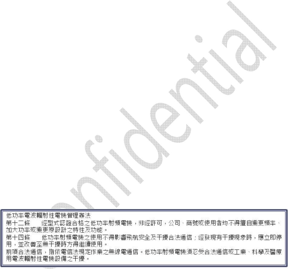
TLM922S-P01A’s firmware can be upgraded through UART by using TLM922S-P01A Flash Tool as shown in
Figure 5. Please make sure the COM port number is the UART interface connected to TLM922S-P01A.
Please be noted that the process should be under normal operation mode.
Figure 4-1
k
iwitec Confidential Documentation 39
FCC Notices
This device complies with Part 15 of the FCC Rules. Operation is subject to the following two conditions: (1) this device
may not cause harmful interference, and (2) this device must accept any interference received, including interference
that may cause undesired operation. This equipment has been tested and found to comply with the limits for a Class B
digital device, pursuant to Part 15 of the FCC Rules. These limits are designed to provide reasonable protection against
harmful interference in a residential installation. This equipment generates, uses and can radiate radio frequency energy
and, if not installed and used in accordance with the instructions, may cause harmful interference to radio communica-
tions. However, there is no guarantee that interference will not occur in a particular installation. If this equipment does
cause harmful interference to radio or television reception, which can be determined by turning the equipment off and
on, the user is encouraged to try to correct the interference by one or more of the following measures:
--Reorient or relocate the receiving antenna.
--Increase the separation between the equipment and receiver.
--Connect the equipment into an outlet on a circuit different from that to which the receiver is connected.
--Consult the dealer or an experienced radio/TV technician for help.
CAUTION:
Any changes or modifications not expressly approved by the grantee of this device could void the user's authority to
operate the equipment.
RF exposure warning:
The equipment complies with FCC RF exposure limits set forth for an uncontrolled environment.
The equipment must not be co-located or operating in conjunction with any other antenna or transmitter.
This equipment should be installed and operated with minimum distance 20cm between the radiator and your body. It
could be removed.
End Product Labeling
This transmitter module is authorized only for use in device where the antenna may be installed such that 20cm may be
maintained between the antenna and users. The final end product must be labeled in a visible area with the following:
"Contains FCC ID: 2AKIBTLM922S”
Information for the OEMs and Integrators
The following statement must be included with all versions of this document supplied to an OEM or integrator, but
should not be distributed to the end user.
1) This device is intended for OEM integrators only.
2) Please see the full Grant of Equipment document for other restrictions.
Manual Information To the End User
The OEM integrator has to be aware not to provide information to the end user regarding how to install or remove this
RF module in the user’s manual of the end product which integrates this module.
The end user manual shall include all required regulatory information/warming as shown in this manual.
k
iwitec Confidential Documentation 40
Antenna List
M
odel
G
ain
Supplier
SPEC
-
RFA
-
09
-
C2M2
-
U
-
M70
-
1
2
dBi
A
ristotle
SPEC
-
RFA
-
09
-
C2M2
-
U
-
M70
2
dBi
A
ristotle
3GD
-
D02
2dBi
GSC
-
TECH
3GD
-
D0
5
2dBi
GSC
-
TECH
3GD
-
D0
6
2dBi
GSC
-
TECH
3GD
-
D0
7
2dBi
GSC
-
TECH