Kmart 02969460 1 User Manual TRACTOR Manuals And Guides 1012096L
User Manual: Kmart 02969460-1 02969460-1 KMART TRACTOR - Manuals and Guides View the owners manual for your KMART TRACTOR #029694601. Home:Lawn & Garden Parts:Kmart Parts:Kmart TRACTOR Manual
Open the PDF directly: View PDF ![]() .
.
Page Count: 92
perator's
I:RnFrSMRN°
LAWN TRACTOR
21 HP, Variation Speed
46" Deck
Model No. 247.28885
•Espanol, P. 58
This product has a low emission engine which operates differently
from previously built engines. Before you start the engine, read and
understand this Operator's Manual.
Before using this equipment,
read this manual and follow
all safety rules and operating
instructions.
For answers to your questions about
this product, Call:
1-800=659=5917
CraftsmanTractorHelp Line
7am = 7 pm CT, Mort. =Sun.
Sears Brands Management Corporation, Hoffman Estates, IL 60179 U.S.A.
Visit our website: www.craftsman.com FormNo.769-06474
(November15,2010)
Off-Season Storage ........................................................ 27
Trou bleshooting .............................................................. 28
Labels ............................................................................. 29
Parts List ......................................................................... 30
Espafiol ............................................................................ 58
Service Numbers ............................................. Back Cover
CRAFTSMAN TWO YEAR FULL WARRANTY
FORTWOYEARSfromthedate of purchase,if anynon-expendablepart of this ridingequipmentfailsdue to adefect inmaterialor workman-
ship,visit www.craftsman.com or call 1-800-659-5917to arrangefor free in-homerepair.
Theframeandfrontaxle will berepairedfreeof chargefor fiveyearsfromthedate of purchaseif defectiveinmaterialorworkmanship.
In allcases,ifrepairprovesimpossible,the ridingequipmentwillbe replacedfree of chargewiththe sameoran equivalentmodel.
Thebatterywill be replacedfree of chargefor 90 daysfromthe dateof purchaseif defectiveinmaterialor workmanship(ourtestingprovesthatit
willnot holda charge).
Thiswarrantyisvoidif thisproductiseverusedwhile providingcommercialservicesorif rentedto anotherperson.
This warranty covers ONLYdefects in materialand workmanship. Warranty coverage does NOTinclude:
• Expendableitemsthatcanwearout fromnormalusewithinthe warrantyperiod,includingbut not limitedto blades,sparkplugs,air
cleaners,belts,andoilfilters.
• Standardmaintenanceservicing,oilchanges,or tune-ups.
Tire replacementor repaircausedby puncturesfromoutsideobjects,suchas nails,thorns,stumps,or glass.
Tireorwheel replacementor repairresultingfromnormalwear,accident,or improperoperationor maintenance.
Repairsnecessarybecauseof operatorabuse,includingbutnot limitedto damagecausedby towingobjectsbeyondthecapabilityof
the ridingequipment,impactingobjectsthatbendthe frameor crankshaft,or over-speedingtheengine.
Repairsnecessarybecauseof operatornegligence,includingbut not limitedto,electricalandmechanicaldamagecausedbyimproper
storage,failureto usethe propergradeandamountof engineoil, failureto keepthe deckclear of flammabledebris,or failureto
maintainthe ridingequipmentaccordingto the instructionscontainedinthe operator'smanual.
• Engine(fuelsystem)cleaningor repairscausedby fuel determinedto becontaminatedoroxidized(stale).In general,fuel shouldbe
usedwithin30 daysof itspurchasedate.
Normaldeteriorationandwearof the exteriorfinishes,or productlabelreplacement.
Thiswarrantygivesyou specificlegalrights,andyou mayalso haveotherrightswhichvaryfromstateto state.
Sears Brands ManagementCorporation, HoffmanEstates, IL 60179
EngineOil: SAE30
Fuel: UnleadedGasoline
SparkPlug: Champion®RC12YC
Engine: Briggs& Stratton
Model Number:
Serial Number:
Dateof Purchase:
Recordthe modelnumber,serialnumber,
anddateof purchaseabove.
© KCDIRLLC 2
Thissymbolpointsout importantsafetyinstructionswhich,if not
followed,couldendangerthepersonalsafetyand/orpropertyof
yourselfandothers. Readandfollowall instructionsin thismanual
beforeattemptingto operatethismachine.Failureto complywith
theseinstructionsmayresultin personalinjury.Whenyou seethis
symbol,HEEDITSWARNING!
CALIFORNIA PROPOSITION 65
EngineExhaust,someof itsconstituents,andcertainvehicle
componentscontainoremit chemicalsknownto Stateof California
to causecancerandbirthdefectsorother reproductiveharm.
Batteryposts,terminals,and relatedaccessoriescontainleadand
leadcompounds,chemicalsknownto the Stateof Californiato
causecancerandreproductiveharm.Washhandsafterhandling.
Thismachinewasbuiltto beoperatedaccordingto the safeopera-
tion practicesinthis manual.As withanytypeof powerequipment,
carelessnessorerroron the partof the operatorcan resultin serious
injury.Thismachineis capableof amputatingfingers,hands,toes
andfeetandthrowingdebris.Failureto observethe followingsafety
instructionscouldresultin seriousinjuryor death.
Your Responsibility--Restrictthe use of this powermachineto
personswho read,understandandfollowthewarningsand instruc-
tionsin thismanualandon the machine.
SAVE THESE INSTRUCTIONS!
GENERAL OPERATION
•Read,understand,andfollowall instructionson the machineand
in themanual(s)beforeattemptingto assembleandoperate.
Keepthis manualina safeplacefor futureand regularreference
andfor orderingreplacementparts.
• Befamiliarwithall controlsandtheir properoperation.Knowhow
to stopthe machineanddisengagethemquickly.
• Neverallowchildrenunder14yearsoldto operatethis machine.
Children14yearsoldandover shouldreadandunderstandthe
operationinstructionsandsafetyrulesinthismanualandshould
betrainedandsupervisedbya parent.
• Neverallowadultsto operatethis machinewithoutproper
instruction.
• Tohelpavoidbladecontactor a thrownobjectinjury,keep
bystanders,helpers,childrenandpetsat least75feetfromthe
machinewhile it is in operation.Stopmachineif anyoneenters
the area.
• Thoroughlyinspectthe areawherethe equipmentis to be used.
Removeallstones,sticks,wire,bones,toys,andotherforeign
objectswhichcouldbe pickedupandthrownby the blade(s).
Thrownobjectscan causeseriouspersonalinjury.
• Planyour mowingpatternto avoiddischargeof materialtoward
roads,sidewalks,bystandersandthe like.Also,avoiddischarg-
ingmaterialagainstawall orobstructionwhichmaycause
dischargedmaterialto ricochetbacktowardthe operator.
• Alwayswear safetyglassesor safetygogglesduringoperation
andwhile performingan adjustmentor repairto protectyoureyes.
Thrownobjectswhichricochetcancauseseriousinjuryto the
eyes.
• Wearsturdy,rough-soledworkshoesandclose-fittingslacksand
shirts.Loosefittingclothesandjewelrycanbe caughtin movable
parts.Neveroperatethismachineinbarefeetorsandals.
• Beawareof the mowerandattachmentdischargedirectionand
do not pointit at anyone.Donot operatethe mowerwithoutthe
dischargecoverorentiregrasscatcherin its properplace.
Donot put handsor feetnearrotatingpartsor underthe cutting
deck. Contactwiththe blade(s)can amputatehandsandfeet.
A missingor damageddischargecovercan causebladecontact
or thrownobjectinjuries.
• Stoptheblade(s)whencrossinggraveldrives,walks,or roads
andwhile notcuttinggrass.
• Watchfor trafficwhenoperatingnearorcrossingroadways.This
machineis not intendedfor useonany public roadway.
• Donot operatethe machinewhile underthe influenceof alcohol
or drugs.
• Mowonly indaylightorgoodartificiallight.
Nevercarrypassengers.
• Disengageblade(s)beforeshiftinginto reverse.Backup slowly.
Alwayslookdownandbehindbeforeandwhile backingto avoida
back-overaccident.
3
• Slowdownbeforeturning.Operatethe machinesmoothly.Avoid
erraticoperationandexcessivespeed.
Disengageblade(s),setparkingbrake,stopengineandwaituntil
the blade(s)cometo a completestopbeforeremovinggrass
catcher,emptyinggrass,uncloggingchute,removinganygrassor
debris,or makinganyadjustments.
Neverleavea runningmachineunattended.Alwaysturnoff
blade(s),setparkingbrake,stopengineandremovekeybefore
dismounting.
Useextracare whenloadingorunloadingthe machineintoa
trailerortruck.Thismachineshouldnot bedrivenupor down
ramp(s),becausethe machinecouldtip over,causingserious
personalinjury.The machinemustbe pushedmanuallyon
ramp(s)to loador unloadproperly.
Mufflerandenginebecomehotandcan causea burn.Do not
touch.
Checkoverheadclearancescarefullybeforedrivingunderlow
hangingtree branches,wires,dooropeningsetc.,wherethe
operatormaybe struckor pulledfromthe machine,whichcould
resultinseriousinjury.
Disengageallattachmentclutchesanddepressthe brakepedal
completelybeforeattemptingto start engine.
Yourmachineisdesignedto cutnormalresidentialgrassof a
heightnomorethan 10".Do not attemptto mowthroughunusually
tall,dry grass(e.g.,pasture)orpiles of dry leaves.Drygrassor
leavesmaycontactthe engineexhaustand/or builduponthe
mowerdeckpresentinga potentialfire hazard.
Useonlyaccessoriesandattachmentsapprovedfor this machine
by the machinemanufacturer.Read,understandandfollowall
instructionsprovidedwiththe approvedaccessoryor attachment.
Fora list of approvedaccessoriesandattachments,call 1-800-
659-5917.
Dataindicatesthatoperators,age60yearsandabove,are
involvedin a largepercentageof ridingmower-relatedinjuries.
Theseoperatorsshouldevaluatetheirabilityto operatethe riding
mowersafelyenoughto protectthemselvesandothersfrom
seriousinjury.
If situationsoccurwhicharenot coveredinthismanual,usecare
andgoodjudgment.Contact1-800-659-5917for informationand
assistance.
SLOPE OPERATION
Slopesarea majorfactorrelatedto lossof controlandtip-over
accidentswhichcan resultinsevereinjuryor death.Allslopesrequire
extracaution.If youcannotbackupthe slopeor if youfeel uneasyon
it, do not mowit.
Foryoursafety,use the SlopeGuideincludedas partof this manual
to measureslopesbeforeoperatingthis machineona slopedor hilly
area. Ifthe slopeis greaterthan15degreesas shownonthe Slope
Guide,do notoperatethis machineonthatareaor seriousinjurycould
result.
Do:
oMowupanddown slopes,not across.Exerciseextremecaution
whenchangingdirectionon slopes.
• Watchfor holes,ruts,bumps,rocks,orother hiddenobjects.
Uneventerraincouldoverturnthe machine.Tallgrasscan hide
obstacles.
Useslowspeed.Choosea lowenoughspeedsettingso that
you will nothaveto stopor shiftwhileon the slope.Tiresmay
lose tractionon slopeseventhoughthe brakesarefunctioning
properly.Alwayskeepmachinein gearwhen goingdownslopes
to takeadvantageof enginebrakingaction.
• Followthe manufacturer'srecommendationsfor wheelweights
or counterweightsto improvestability.Forrecommendations,call
1-800-659-5917.
• Useextracarewithgrasscatchersor otherattachments.These
can changethe stabilityof the machine.
Keepallmovementonthe slopesslowandgradual.Do not make
suddenchangesinspeedor direction.Rapidengagementor
brakingcouldcausethe frontof the machineto lift andrapidlyflip
overbackwardswhichcouldcauseseriousinjury.
• Avoidstartingorstoppingona slope.Iftireslosetraction,disen-
gagethe blade(s)andproceedslowlystraightdownthe slope.
DoNot:
• Donot turnon slopesunlessnecessary;then,turnslowlyand
graduallydownhill,if possible.
• Donot mowneardrop-offs,ditchesor embankments.The mower
could suddenlyturnover if a wheelis overthe edgeof a cliff,
ditch,or if an edgecavesin.
• Donot try to stabilizethe machineby puttingyourfooton the
ground.
• Donot usea grasscatcheron steepslopes.
• Donot mowon wetgrass.Reducedtractioncouldcausesliding.
• Donot attemptto coastdownhill.Over-speedingmaycausethe
operatorto lose controlof the machineresultingin seriousinjury
or death.
• Donot towheavypull behindattachments(e.g.loadeddumpcart,
lawn roller,etc.)on slopesgreaterthan5 degrees.Whengoing
down hill,the extraweighttendsto pushthe tractorandmay
causeyou to loosecontrol(e.g.tractormay speedup, brakingand
steeringabilityarereduced,attachmentmayjack-knifeandcause
tractorto overturn).
4
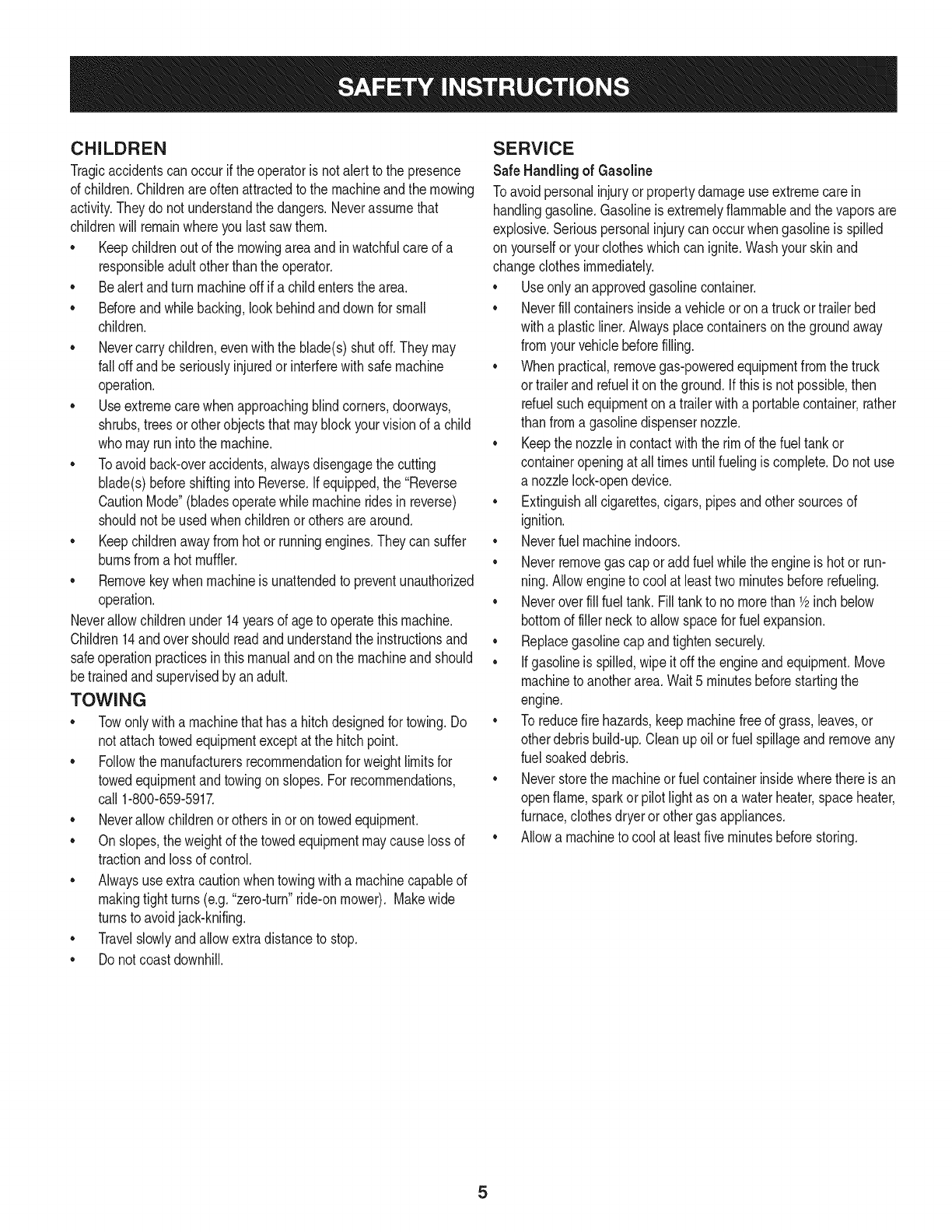
CHILDREN
Tragicaccidentscanoccurifthe operatoris notalert to the presence
of children.Childrenareoftenattractedto the machineandthe mowing
activity.Theydo notunderstandthe dangers.Neverassumethat
childrenwill remainwhereyou lastsawthem.
• Keepchildrenout of the mowingareaand inwatchfulcare of a
responsibleadultotherthanthe operator.
• Bealert andturnmachineoff ifa childentersthe area.
• Beforeandwhilebacking,lookbehindanddownfor small
children.
Nevercarrychildren,evenwiththe blade(s)shutoff.Theymay
fall offandbe seriouslyinjuredorinterferewithsafemachine
operation.
• Useextremecarewhenapproachingblindcorners,doorways,
shrubs,treesor otherobjectsthatmayblockyourvisionof a child
whomayrunintothe machine.
Toavoidback-overaccidents,alwaysdisengagethe cutting
blade(s)beforeshiftingintoReverse.Ifequipped,the "Reverse
CautionMode"(bladesoperatewhilemachineridesinreverse)
shouldnotbe usedwhenchildrenor othersarearound.
Keepchildrenawayfromhotor runningengines.Theycansuffer
burnsfroma hotmuffler.
• Removekeywhenmachineisunattendedto preventunauthorized
operation.
Neverallowchildrenunder14yearsof ageto operatethis machine.
Children14andovershouldreadandunderstandthe instructionsand
safeoperationpracticesinthismanualandon the machineandshould
betrainedandsupervisedbyan adult.
TOWING
Towonlywitha machinethathasa hitchdesignedfor towing.Do
not attachtowedequipmentexceptat the hitchpoint.
Followthe manufacturersrecommendationforweightlimitsfor
towedequipmentandtowingonslopes.For recommendations,
call 1-800-659-5917.
Neverallowchildrenor othersinoron towedequipment.
Onslopes,theweightof thetowedequipmentmaycauselossof
tractionandlossof control.
Alwaysuseextracautionwhentowingwitha machinecapableof
makingtightturns(e.g."zero-turn"ride-onmower). Makewide
turnsto avoidjack-knifing.
Travelslowlyandallowextradistanceto stop.
Do notcoastdownhill.
SERVICE
SafeHandlingof Gasoline
Toavoidpersonalinjuryorpropertydamageuse extremecarein
handlinggasoline.Gasolineisextremelyflammableandthe vaporsare
explosive.Seriouspersonalinjurycanoccurwhengasolineis spilled
on yourselforyour clotheswhichcan ignite.Washyourskinand
changeclothesimmediately.
• Useonly anapprovedgasolinecontainer.
Neverfill containersinsidea vehicleoron a truckortrailer bed
witha plasticliner.Alwaysplacecontainerson the groundaway
fromyourvehiclebeforefilling.
Whenpractical,removegas-poweredequipmentfromthe truck
or trailerandrefueliton theground.Ifthis isnot possible,then
refuelsuchequipmentona trailerwitha portablecontainer,rather
than froma gasolinedispensernozzle.
Keepthe nozzleincontactwiththe rim of the fueltankor
containeropeningat all timesuntilfuelingiscomplete.Donot use
a nozzlelock-opendevice.
Extinguishall cigarettes,cigars,pipesandothersourcesof
ignition.
• Neverfuel machineindoors.
Neverremovegascap or addfuelwhilethe engineis hotor run-
ning.Allowengineto coolat leasttwominutesbeforerefueling.
Neveroverfill fuel tank. Filltankto no morethan 1/2inchbelow
bottomof filler neckto allowspaceforfuel expansion.
• Replacegasolinecap andtightensecurely.
• Ifgasolineis spilled,wipeitoff the engineandequipment.Move
machineto anotherarea.Wait5 minutesbeforestartingthe
engine.
• To reducefire hazards,keepmachinefree of grass,leaves,or
otherdebrisbuild-up.Cleanup oilor fuel spillageandremoveany
fuel soakeddebris.
• Neverstorethe machineor fuelcontainerinsidewherethere isan
openflame,sparkor pilotlight as ona waterheater,spaceheater,
furnace,clothesdryeror othergasappliances.
Allowa machineto coolat leastfiveminutesbeforestoring.
GeneralService
• Neverrunanengineindoorsorinapoorlyventilatedarea.Engine
exhaustcontainscarbonmonoxide,anodorless,anddeadlygas.
• Beforecleaning,repairing,orinspecting,makecertainthe
blade(s)andallmovingpartshavestopped.Disconnectthespark
plugwireandgroundagainsttheenginetopreventunintended
starting.
• Periodicallychecktomakesurethebladescometocomplete
stopwithinapproximately(5)fivesecondsafteroperatingthe
bladedisengagementcontrol.Ifthebladesdonotstopwithinthe
thistimeframe,yourmachineshouldbeservicedprofessionally
byaSearsorotherqualifiedservicedealer.
• Checkbrakeoperationfrequentlyasitissubjectedtowearduring
normaloperation.Adjustandserviceasrequired.
• Checktheblade(s)andenginemountingboltsatfrequent
intervalsforpropertightness.Also,visuallyinspectblade(s)
fordamage(e.g.,excessivewear,bent,cracked).Replacethe
blade(s)withtheoriginalequipmentmanufacturer's(O.E.M.)
blade(s)only,listedinthismanual.Useofpartswhichdonot
meettheoriginalequipmentspecificationsmayleadtoimproper
performanceandcompromisesafety!
• Mowerbladesaresharp.Wrapthebladeorweargloves,anduse
extracautionwhenservicingthem.
• Keepallnuts,bolts,andscrewstighttobesuretheequipmentis
insafeworkingcondition.
• Nevertamperwiththe safetyinterlocksystemor othersafety
devices.Checktheir properoperationregularly.
• Afterstrikinga foreignobject,stopthe engine,disconnectthe
sparkplugwire(s)andgroundagainstthe engine.Thoroughly
inspectthe machinefor anydamage.Repairthe damagebefore
startingandoperating.
• Neverattemptto makeadjustmentsor repairsto the machine
whilethe engineis running.
• Grasscatchercomponentsandthe dischargecoverare subject
to wearanddamagewhichcouldexposemovingpartsor allow
objectsto bethrown.Forsafetyprotection,frequentlycheck
componentsand replaceimmediatelywithoriginalequipment
manufacturer's(O.E.M.)partsonly,listedinthis manual.Useof
partswhichdo not meetthe originalequipmentspecificationsmay
leadto improperperformanceandcompromisesafety!
• Donot changethe enginegovernorsettingsorover-speedthe
engine.The governorcontrolsthe maximumsafeoperatingspeed
of the engine.
Maintainor replacesafetyandinstructionlabels,as necessary.
• Observeproperdisposallawsandregulationsfor gas,oil, etc.to
protecttheenvironment.
• Accordingto the ConsumerProductsSafetyCommission(CPSC)
andthe U.S.EnvironmentalProtectionAgency(EPA),this product
has anAverageUsefulLifeof seven(7)years,or 270hours
of operation.At the endof the AverageUsefulLife,buy anew
machineor havethe machineinspectedannuallybya Searsor
otherqualifiedservicedealerto ensurethatall mechanicaland
safetysystemsareworkingproperlyandnot wornexcessively.
Failureto doso can resultinaccidents,injuriesor death.
DO NOT MODIFY ENGINE
Toavoid seriousinjuryor death,do notmodifyengineinanyway.
Tamperingwiththe governorsettingcanleadto a runawayengineand
causeit to operateat unsafespeeds.Nevertamperwithfactorysetting
of enginegovernor.
NOTICE REGARDING EMISSIONS
Engineswhicharecertifiedto complywithCaliforniaandfederal
EPAemissionregulationsfor SORE(SmallOffRoadEquipment)are
certifiedto operateon regularunleadedgasoline,andmayinclude
the followingemissioncontrolsystems:EngineModification(EM)and
ThreeWayCatalyst(TWO)if so equipped.
SPARK ARRESTOR
Thismachineis equippedwithan internalcombustionengineand
shouldnotbe usedonor nearanyunimprovedforest-covered,
brushcoveredorgrass-coveredlandunlessthe engine'sexhaust
systemisequippedwitha sparkarrestormeetingapplicablelocalor
statelaws(if any).
Ifa sparkarrestoris used,it shouldbe maintainedin effectiveworking
orderby the operator.Inthe Stateof Californiatheaboveis required
by law (Section4442of the CaliforniaPublicResourcesCode).Other
statesmayhavesimilarlaws.Federallawsapplyonfederallands.
A sparkarrestorfor the muffleris availablethroughyournearestSears
PartsandRepairServiceCenter.
6
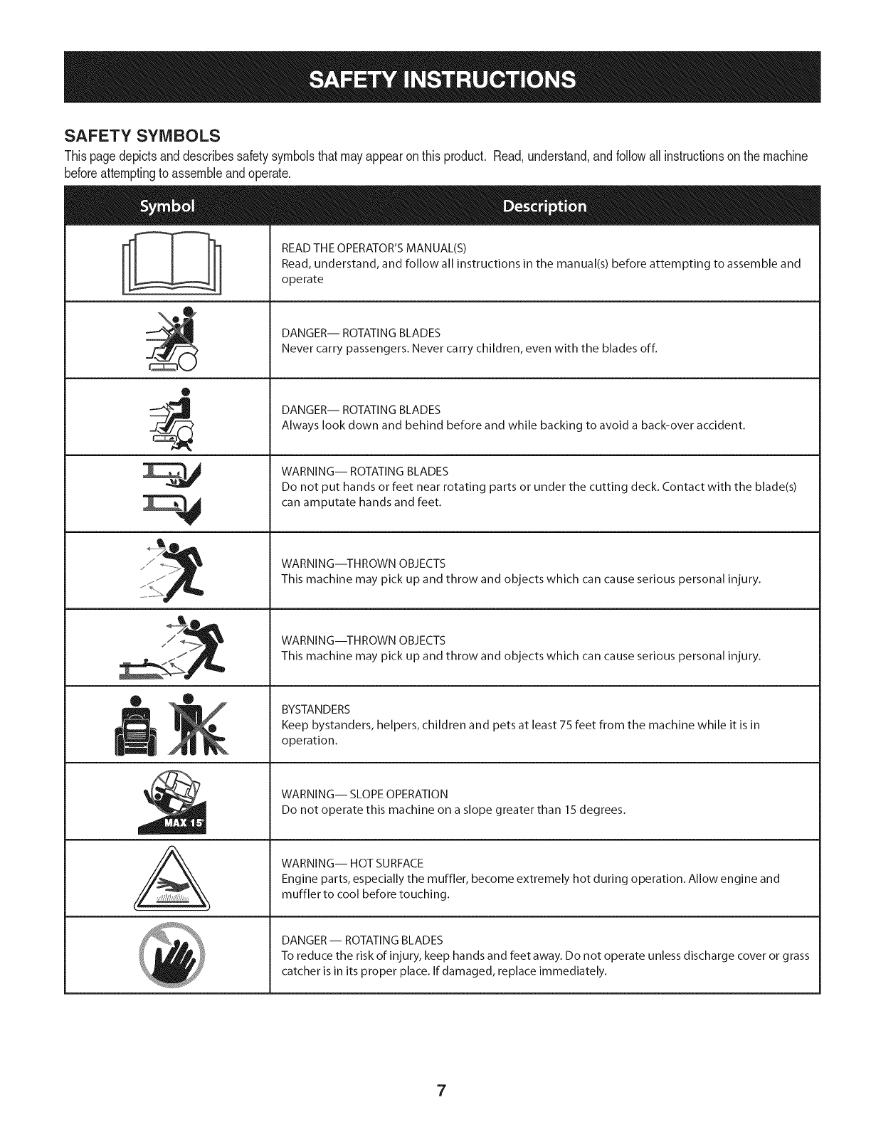
SAFETY SYMBOLS
Thispagedepictsanddescribessafetysymbolsthatmayappearonthis product. Read,understand,andfollowallinstructionson the machine
beforeattemptingto assembleandoperate.
O
A
READ THE OPERATOR'S MANUAL(S)
Read, understand, and follow all instructions in the manual(s) before attempting to assemble and
operate
DANGER-- ROTATING BLADES
Never carry passengers. Never carry children, even with the blades off.
DANGER-- ROTATING BLADES
Always look down and behind before and while backing to avoid a back-over accident.
WARNING-- ROTATING BLADES
Do not put hands or feet near rotating parts or under the cutting deck. Contact with the blade(s)
can amputate hands and feet.
WARNING--THROWN OBJECTS
This machine may pick up and throw and objects which can cause serious personal injury.
WARNING--THROWN OBJECTS
This machine may pick up and throw and objects which can cause serious personal injury.
BYSTANDERS
Keep bystanders, helpers, children and pets at least 75 feet from the machine while it is in
operation.
WARNING-- SLOPE OPERATION
Do not operate this machine on a slope greater than 15 degrees.
WARNING-- HOT SURFACE
Engine parts, especially the muffler, become extremely hot during operation. Allow engine and
muffler to cool before touching.
DANGER- ROTATING BLADES
To reduce the risk of injury, keep hands and feet away. Do not operate unless discharge cover or grass
catcher is in its proper place. If damaged, replace immediately.
7
0o
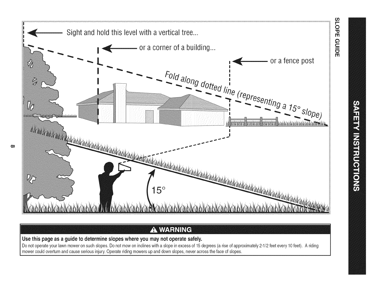
Sight and hold this levelwith a vertical tree...
or a corner of a building...
15 °
Use this page as a guideto determine slopes where you may not operate safely.
Donot operateyourlawnmoweron suchslopes.Do notmowon inclineswitha slope inexcessof 15degrees(a rise of approximately2-1/2feetevery10feet). A riding
mowercouldoverturnand causeseriousinjury.Operateridingmowersupanddownslopes,neveracrossthe faceof slopes.
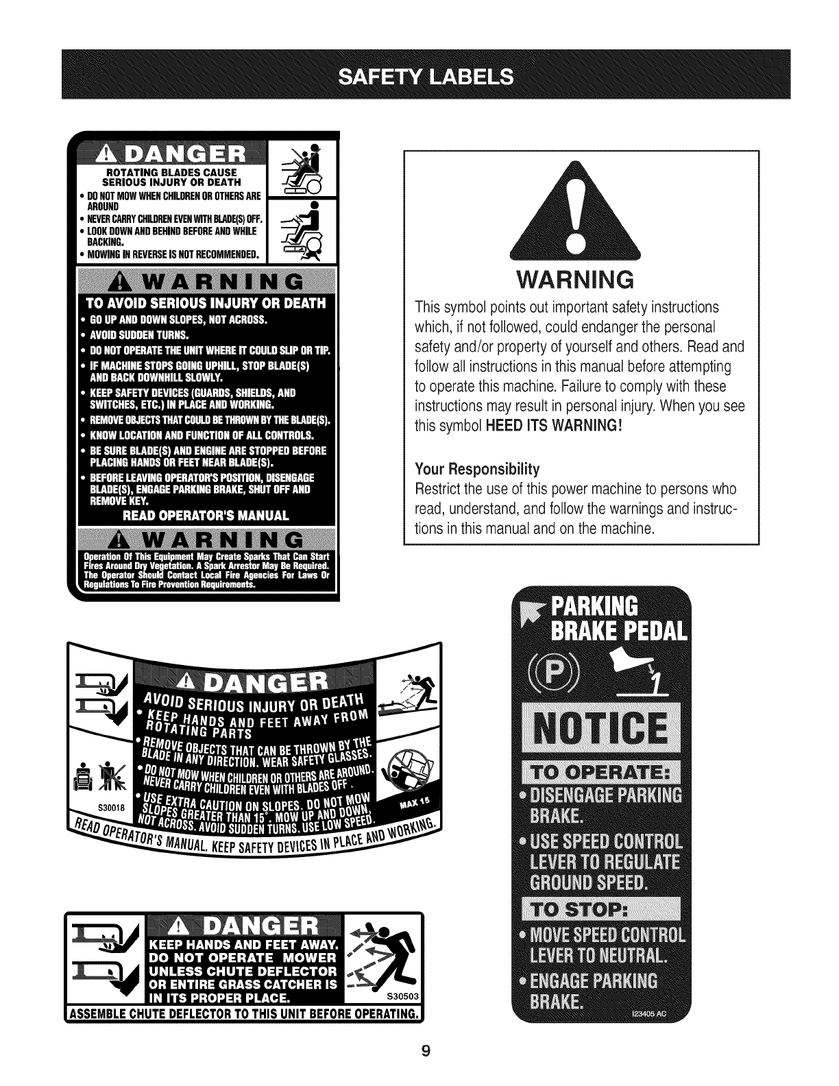
ROTATING BLADES CAUSE
SERIOUS INJURY OR DEATH
DONOTMOWWHENCHILDRENOROTHERSARE
AROUND
NEVERCARRYCHILDRENEVENWITHBLADE(S)OFF.
LOOKDOWNANDBEHINDBEFOREANDWHILE
BACKING.
MOWINGINREVERSEISNOTRECOMMENDED.
WARNING
This symbol points out important safety instructions
which, if notfollowed, could endangerthe personal
safety and/or property of yourself and others. Readand
follow all instructions inthis manual before attempting
to operatethis machine. Failure to comply with these
instructions may result in personal injury.When you see
this symbol HEED ITS WARNING!
Your Responsibility
Restrictthe use of this power machineto persons who
read, understand,and follow the warnings and instruc-
tions in this manual and on the machine.
9
IMPORTANT:Yourtractoris shippedwithmotoroil in theengine.
However,you MUSTcheckthe oil levelbeforeoperating.Referto the
Service& Maintenancesectionfor instructionson checkingtheoil
level.
Attaching the Battery Cables
CALIFORNIA PROPOSITION 65
Batteryposts,terminals,andrelatedaccessoriescontainleadand
leadcompounds,chemicalsknownto the Stateof Californiato
causecancerandreproductiveharm.Washhandsafterhandling.
Whenattachingbatterycables,alwaysconnectthe POSITIVE(Red)
wireto its terminalfirst,followedby the NEGATIVE(Black)wire.
Forshippingreasons,bothbatterycablesonyourequipmenthave
beenleftdisconnectedfromthe terminalsat the factory.Toconnect
the batterycables,proceedas follows:
NOTE:Thepositivebatteryterminalis markedPos.(+).The negative
batteryterminalis markedNeg.(i).
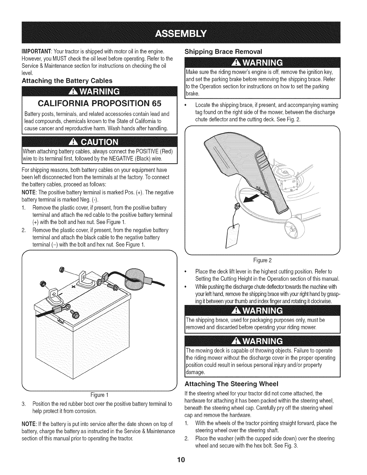
1. Removethe plasticcover,if present,fromthe positivebattery
terminaland attachthe redcableto the positivebatteryterminal
(+)withthe bolt andhexnut.See Figure1.
2. Removethe plasticcover,if present,fromthe negativebattery
terminaland attachthe blackcableto the negativebattery
terminal(-) withthe bolt andhex nut.SeeFigure1.
f
J
Figure1
3. Positionthe redrubberbootoverthe positivebatteryterminalto
helpprotectit fromcorrosion.
NOTE:If thebatteryis put into serviceafterthe dateshownon topof
battery,chargethe batteryas instructedinthe Service& Maintenance
sectionof this manualpriorto operatingthe tractor.
Shipping Brace Removal
Makesurethe ridingmower'sengineis off, removetheignitionkey,
andset the parkingbrakebeforeremovingthe shippingbrace.Refer
Itothe Operationsectionfor instructionsonhowto setthe parking
lbrake.
• Locatethe shippingbrace,if present,andaccompanyingwarning
tag foundonthe rightsideof the mower,betweenthe discharge
chutedeflectorandthe cuttingdeck. SeeFig.2.
Figure2
Placethe decklift leverinthe highestcuttingposition.Referto
SettingtheCuttingHeightin the Operationsectionof thismanual.
Whilepushingthedischargechuteddlectortowardsthemachinewith
yourlefthand,removetheshippingbracewithyourrighthandbygrasp-
ingitbetweenyourthumbandindexfingerandrotatingitclockwise.
The shippingbrace,usedfor packagingpurposesonly,mustbe
removedand discardedbeforeoperatingyour ridingmower.
The mowingdeck iscapableof throwingobjects.Failureto operate
the ridingmowerwithoutthe dischargecoverin the properoperating
Ipositioncould resultin seriouspersonalinjuryand/orproperty
ldamage.
Attaching The Steering Wheel
Ifthe steeringwheelfor yourtractordid notcomeattached,the
hardwarefor attachingit has beenpackedwithinthe steeringwheel,
beneaththe steeringwheelcap.Carefullypry off the steeringwheel
cap andremovethe hardware.
1. Withthe wheelsof the tractorpointingstraightforward,placethe
steeringwheeloverthe steeringshaft.
2. Placethe washer(withthe cuppedsidedown)overthe steering
wheeland securewiththe hex bolt.SeeFig.3.
10
f..-
\
Figure3
3. Placethe steeringwheelcap overthe centerof the steering
wheeland pushdownwarduntilit "clicks"intoplace.
Attaching The Seat
NOTE:Forshippingreasons,the seatis eitherfastenedtothe tractor
seat'spivotbracketwitha plastictie,or mountedbackwardto the pivot
bracket.Ineithercase,free the seatfromits shippingpositionbeing
carefulnotto bendor kinkthe wiringharnessandfollowtheinstruc-
tionsbelowto attach it.
1. Removethetwo hexscrewsandnutsfromthe seatpivotbracket.
2. Alignthefrontholesof the seatmountingbracketwiththe holesin
the seatpivotbracketon yourtractorand securewith previously
removedhex screwsandnuts. SeeA in Figure4.
3. Plugthe wiringharnessintothe seatsafetyswitchinthe bottomof
the seat,as shownin Bof Figure4.
NOTE:The tractorwill not operatewiththe wiringharness
disconnected.
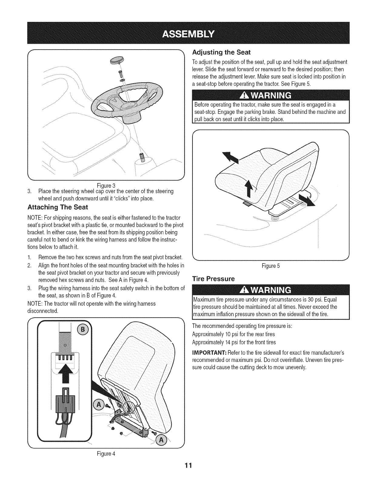
Adjusting the Seat
Toadjustthe positionof the seat,pullupandholdthe seatadjustment
lever.Slidethe seatforwardor rearwardto thedesiredposition;then
releasethe adjustmentlever.Makesure seatis lockedintopositionin
a seat-stopbeforeoperatingthe tractor.SeeFigure5.
Beforeoperatingthe tractor,makesurethe seatis engagedina
seat-stop.Engagethe parkingbrake.Standbehindthe machineand
pull backon seatuntil it clicksintoplace.
Figure5
Tire Pressure
Maximumtire pressureunderany circumstancesis 30 psi.Equal
tire pressureshouldbe maintainedat all times.Neverexceedthe
_maxmum nfat onpressureshownonthe s dewa of thet re.
The recommendedoperatingtire pressureis:
Approximately10psi forthe reartires
Approximately14psifor the fronttires
iMPORTANT: Referto the tire sidewallfor exacttire manufacturer's
recommendedormaximumpsi.Donot overinfiate.Uneventirepres-
surecouldcausethe cuttingdeckto mowunevenly.
Figure4
11
B
C
D
E
G
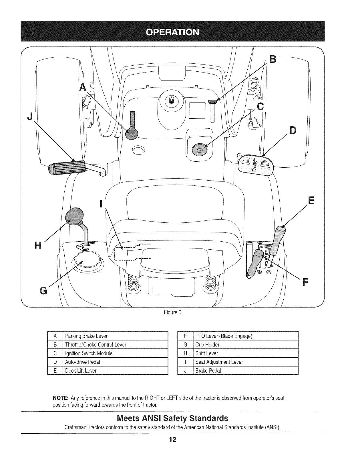
Figure6
F
J
A ParkingBrakeLever
B Throttle/ChokeControlLever
C IgnitionSwitchModule
D Auto-drivePedal
E DeckLift Lever
F PTOLever(BladeEngage)
G Cup Holder
H ShiftLever
I SeatAdjustmentLever
J BrakePedal
NOTE: Any referencein thismanualto the RIGHTor LEFTsideof the tractoris observedfromoperator'sseat
positionfacingforwardtowardsthe frontof tractor.
Meets ANSi Safety Standards
CraftsmanTractorsconformto the safetystandardof theAmericanNationalStandardsInstitute(ANSI).
12
PARKING BRAKE LEVER
Toset the parkingbrake: Fullydepressthe brakepedal. Movethe
parkingbrakeleverintothe parkingbrakeposition.Releasethe brake
pedalto allowthe parkingbraketo engage.
To release the parkingbrake: Depressthe brakepedalandthe park-
ingbrakeleverwill moveoutof the parkingbrakepositionon itsown.
Theparkingbrakewillthen bereleased.Releasethe brakepedal.
NOTE: The parkingbrakemustbe setif the operatorleavesthe seat
withthe enginerunningor the enginewill automaticallyshutoff.
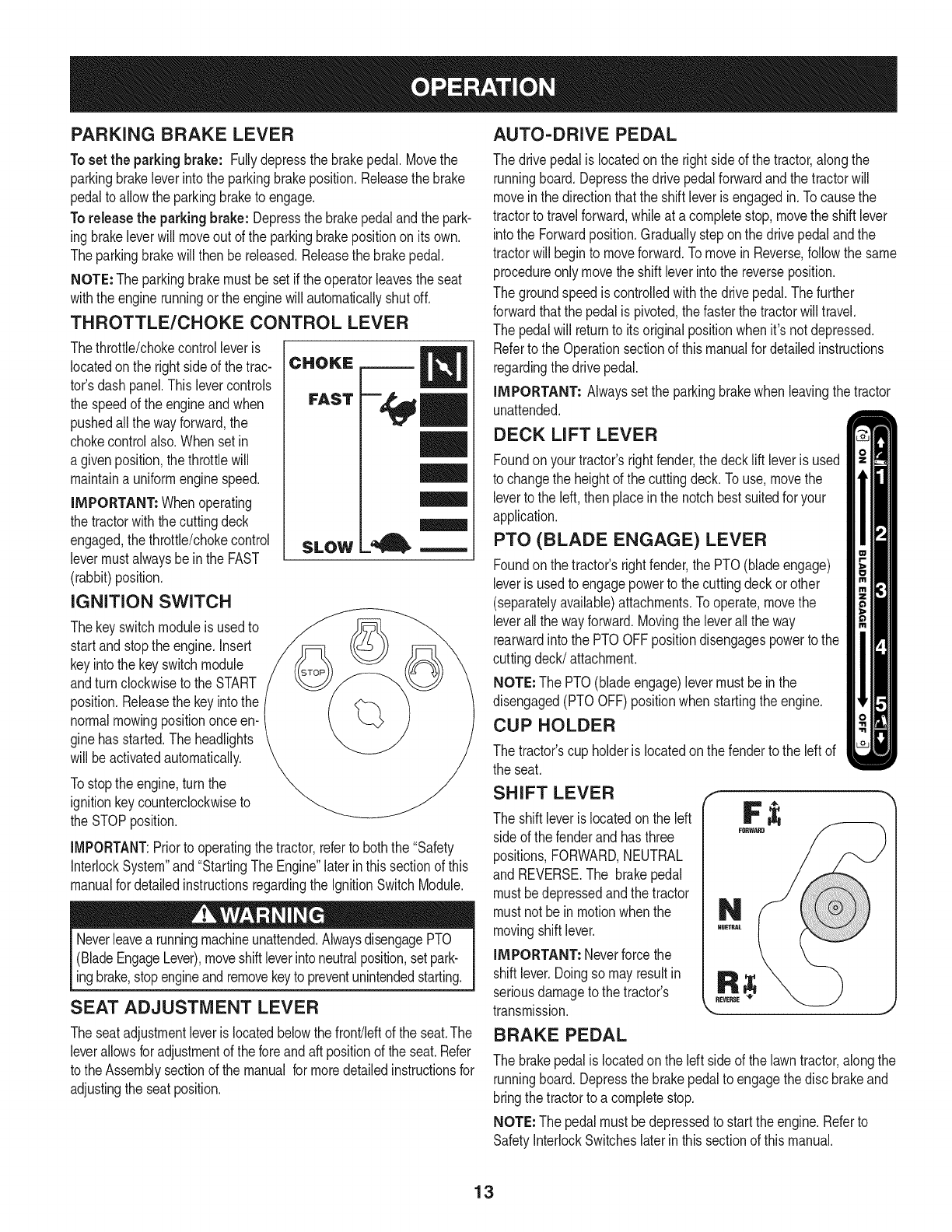
THROTTLE/CHOKE CONTROL LEVER
Thethrottle/chokecontrolleveris
locatedonthe right sideof the trac-
tor'sdash panel.This levercontrols
the speedof the engineand when
pushedall thewayforward,the
chokecontrolalso.Whensetin
a givenposition,thethrottlewill
maintaina uniformenginespeed.
IMPORTANT: Whenoperating
the tractorwiththe cuttingdeck
engaged,thethrottle/chokecontrol
levermustalwaysbe inthe FAST
(rabbit)position.
IGNITION SWITCH
Thekeyswitchmoduleisusedto
startand stopthe engine.Insert
keyintothe keyswitchmodule
andturnclockwiseto theSTART
position.Releasethe keyintothe
normalmowingpositiononceen-
ginehasstarted.The headlights
will beactivatedautomatically.
Tostopthe engine,turnthe
ignitionkeycounterclockwiseto
the STOPposition.
CHOKE
FAST
SLOW
l=, m
IMPORTANT:Priorto operatingthe tractor,referto boththe "Safety
InterlockSystem"and"StartingThe Engine"laterinthissectionof this
manualfor detailedinstructionsregardingthe IgnitionSwitchModule.
Neverleavea runningmachineunattended.AlwaysdisengagePTO
(BladeEngageLever),moveshiftleverintoneutralposition,setpark-
ingbrake,stopengineandremovekeyto preventunintendedstarting.
SEAT ADJUSTMENT LEVER
Theseatadjustmentleveris locatedbelowthe front/leftof the seat.The
leverallowsfor adjustmentof the foreandaft positionof the seat.Refer
to theAssemblysectionof themanual formoredetailedinstructionsfor
adjustingthe seatposition.
AUTO-DRIVE PEDAL
The drivepedalislocatedonthe rightside of the tractor,alongthe
runningboard.Depressthe drivepedalforwardandthe tractorwill
moveinthe directionthatthe shiftleveris engagedin. Tocausethe
tractorto travelforward,whileat acompletestop,movethe shift lever
intothe Forwardposition.Graduallysteponthe drivepedalandthe
tractorwill beginto moveforward.Tomovein Reverse,followthe same
procedureonlymovetheshift leverintothe reverseposition.
The groundspeediscontrolledwiththe drivepedal.Thefurther
forwardthatthe pedalis pivoted,thefasterthe tractorwill travel.
The pedalwill returnto its originalpositionwhenit'snot depressed.
Referto the Operationsectionof thismanualfor detailedinstructions
regardingthedrive pedal.
IMPORTANT= Alwayssetthe parkingbrakewhenleavingthe tractor
unattended.
DECK LIFT LEVER
Foundonyour tractor'srightfender,the deckliftleveris used
to changethe heightof the cuttingdeck.To use,movethe
leverto the left, thenplaceinthe notchbestsuitedfor your
application.
PTO (BLADE ENGAGE) LEVER
Foundonthe tractor'srightfender,the PTO(bladeengage)
leveris usedto engagepowerto the cuttingdeckorother
(separatelyavailable)attachments.Tooperate,movethe
leverall thewayforward.Movingthe leverallthe way
rearwardintothe PTOOFFpositiondisengagespowerto the
cuttingdeck/attachment.
NOTE=The PTO(bladeengage)levermustbe inthe
disengaged(PTOOFF)positionwhenstartingthe engine.
CUP HOLDER
The tractor'scup holderis locatedon the fenderto the left of
the seat.
SHIFT LEVER
The shift leveris locatedonthe left
sideof the fenderand hasthree
positions,FORWARD,NEUTRAL
and REVERSE.The brakepedal
mustbedepressedandthe tractor
mustnotbe in motionwhenthe
movingshift lever.
IMPORTANT: Neverforcethe
shiftlever.Doingso mayresultin
seriousdamageto the tractor's
transmission. REVERSE
_J
BRAKE PEDAL
The brakepedalis locatedon the leftside of the lawntractor,alongthe
runningboard.Depressthe brakepedalto engagethe discbrakeand
bringthe tractorto a completestop.
NOTE=The pedalmustbe depressedto startthe engine.Referto
SafetyInterlockSwitcheslaterin thissectionof thismanual.
13
GAS AND OiL FILL-UP
0il
IMPORTANT: Yourtractoris shippedwithmotoroil inthe engine.
However,you MUSTcheckthe oil levelbeforeoperating.Becareful
notto overfill.
Forinstructionsonhowto checkthe engineoil, referto CheckingThe
EngineOilin the ServiceandMaintenancesectionof this manual.
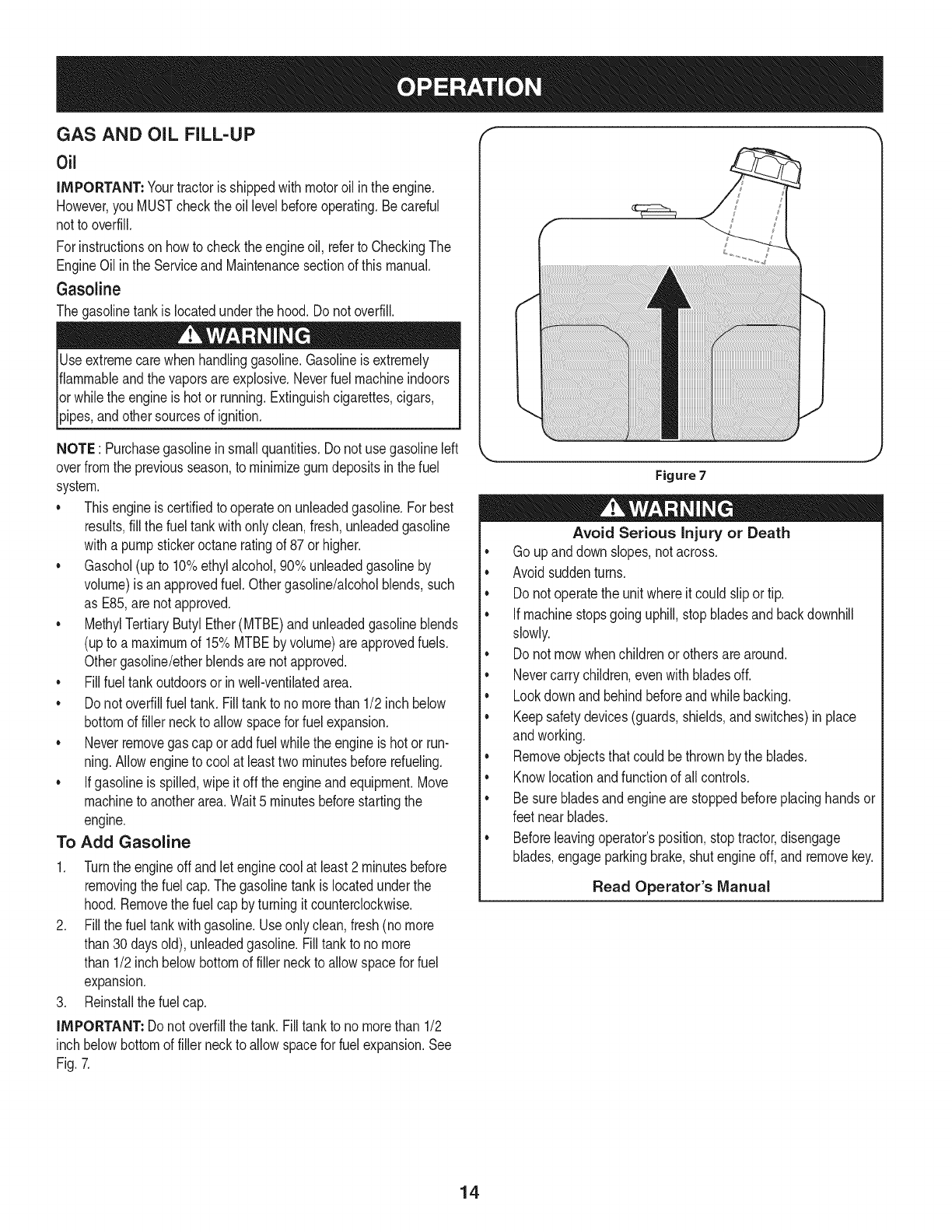
Gasoline
Thegasolinetankis locatedunderthe hood.Do notoverfill.
Useextremecarewhenhandlinggasoline.Gasolineis extremely
flammableandthe vaporsareexplosive.Neverfuel machineindoors
orwhilethe engineis hotor running.Extinguishcigarettes,cigars,
_ppes,andothersourcesof gn t on.
NOTE : Purchasegasolineinsmallquantities.Do notuse gasolineleft
overfromthe previousseason,to minimizegumdepositsin the fuel
system.
• Thisengineis certifiedto operateon unleadedgasoline.For best
results,fill the fueltankwithonlyclean,fresh,unleadedgasoline
witha pumpstickeroctaneratingof 87or higher.
• Gasohol(upto 10%ethylalcohol,90%unleadedgasolineby
volume)is anapprovedfuel.Othergasoline/alcoholblends,such
as E85,arenot approved.
• MethylTertiaryButylEther(MTBE)andunleadedgasolineblends
(upto a maximumof 15%MTBEby volume)are approvedfuels.
Othergasoline/etherblendsare notapproved.
• Fillfuel tankoutdoorsorin well-ventilatedarea.
• Do notoverfillfuel tank. Filltankto no morethan 1/2inch below
bottomof filler neckto allowspacefor fuel expansion.
• Neverremovegas capor addfuel whilethe engineis hot or run-
ning.Allowengineto cool at leasttwo minutesbeforerefueling.
• Ifgasolineis spilled,wipe it off theengineandequipment.Move
machineto anotherarea.Wait5 minutesbeforestartingthe
engine.
To Add Gasoline
1. Turnthe engineoff andlet enginecool at least2 minutesbefore
removingthe fuelcap.The gasolinetankis locatedunderthe
hood.Removethe fuel cap byturningit counterclockwise.
2. Fillthe fuel tankwithgasoline.Useonlyclean,fresh(nomore
than30 daysold), unleadedgasoline.Filltankto nomore
than 1/2inch belowbottomof filler neckto allowspacefor fuel
expansion.
3. Reinstallthe fuelcap.
IMPORTANT: Donot overfillthe tank.Fill tankto no morethan 1/2
inch belowbottomof filler neckto allowspacefor fuel expansion.See
Fig.7.
Figure7
Avoid Serious Injury or Death
• Go upanddownslopes,notacross.
• Avoidsuddenturns.
• Donot operatethe unitwhereit could slipor tip.
• Ifmachinestopsgoinguphill,stopbladesand backdownhill
slowly.
• Donot mowwhenchildrenorothersare around.
• Nevercarrychildren,evenwith bladesoff.
• Lookdownand behindbeforeandwhilebacking.
• Keepsafetydevices(guards,shields,and switches)inplace
andworking.
• Removeobjectsthat couldbethrownby the blades.
• Knowlocationandfunctionof all controls.
• Besurebladesandenginearestoppedbeforeplacinghandsor
feetnearblades.
• Beforeleavingoperator'sposition,stoptractor,disengage
blades,engageparkingbrake,shutengineoff, and removekey.
Read Operator's Manual
14
SAFETY iNTERLOCK SYSTEM
Thesafetyinterlocksystemisdesignedfor safeoperationof thetrac-
tor.Ifthis systemshouldever malfunction,do not operatethe tractor.
Immediatelycontact1-800-4-MY-HOMEto havethe systemserviced.
•Thesafetyinterlocksystempreventsthe enginefromstarting
unlessthe parkingbrakeis engagedandthe PTO(BladeEngage)
leveris in thedisengaged(OFF)position.
•Thesafetyinterlocksystemwill automaticallyshutoffthe engineif
the operatorleavesthe seatbeforeengagingthe parkingbrake.
•Thesafetyinterlocksystemwill automaticallyshutoffthe engine
ifthe operatorleavesthe tractor'sseatwiththe PTO(Blade
Engage)leverengaged,regardlessof whetherthe parkingbrake
is engaged.
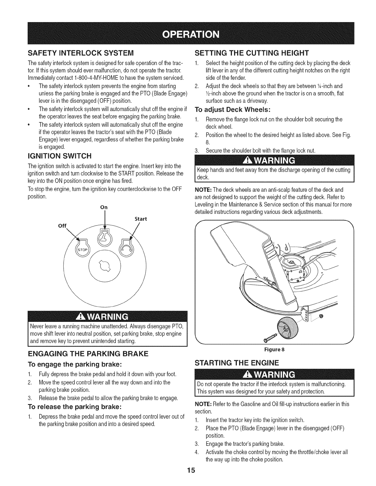
IGNITION SWITCH
Theignitionswitchis activatedto startthe engine,insertkeyintothe
ignitionswitchandturnclockwiseto the STARTposition.Releasethe
keyintothe ON positiononce enginehas fired.
Tostopthe engine,turnthe ignitionkeycounterclockwiseto the OFF
position.
On
Start
off
Neverleavea runningmachineunattended.AlwaysdisengagePTO,
moveshift leverintoneutralposition,setparkingbrake,stopengine
andremovekeyto preventunintendedstarting.
ENGAGING THE PARKING BRAKE
To engage the parking brake:
1. Fullydepressthe brakepedalandholdit downwithyour foot.
2. Movethe speedcontrolleverallthe waydownandintothe
parkingbrakeposition.
3. Releasethe brakepedalto allow theparkingbraketo engage.
To release the parking brake:
1. Depressthe brakepedalandmovethe speedcontrolleverout of
the parkingbrakepositionandintoa desiredspeed.
SETTING THE CUTTING HEIGHT
1. Selectthe heightpositionof the cuttingdeckby placingthe deck
liftleverinanyof the differentcuttingheightnotcheson the right
sideof the fender.
2. Adjustthe deck wheelssothattheyarebetween1A-inchand
Y2-inchabovethe groundwhenthe tractoris ona smooth,fiat
surfacesuchas a driveway.
To adjust Deck Wheels:
1. Removethe flangelocknuton the shoulderbolt securingthe
deckwheel.
2. Positionthe wheelto thedesiredheightas listedabove.SeeFig.
8.
3. Securethe shoulderboltwiththe flangelocknut.
Keephandsandfeetawayfromthe dischargeopeningof the cutting
deck.
NOTE: Thedeckwheelsarean anti-scalpfeatureof the deckand
are notdesignedto supportthe weightof the cuttingdeck. Referto
Levelinginthe Maintenance& Servicesectionof thismanualfor more
detailedinstructionsregardingvariousdeckadjustments.
Figure8
STARTING THE ENGINE
Donot operatethe tractorif the interlocksystemis malfunctioning.
Thissystemwasdesignedfor yoursafetyand protection.
NOTE: Referto the GasolineandOil fill-up instructionsearlierin this
section.
1. Insertthe tractorkeyintothe ignitionswitch.
2. Placethe PTO(BladeEngage)leverin thedisengaged(OFF)
position.
3. Engagethe tractor'sparkingbrake.
4. Activatethechokecontrolby movingthethrottle/chokeleverall
the wayupintothechokeposition.
15
5. Turnthe ignitionkeyclockwiseto the STARTposition.Afterthe
enginestarts,releasethe key.It will returnto the ON (orNormal
Mowing)position.
Do NOTholdthe keyin the STARTpositionfor longerthanten
secondsat a time.Doingso maycausedamageto yourengine's
electricstarter.
6. Afterthe enginestarts,deactivatethe chokecontroland placethe
throttlecontrolinthe FASTposition.
NOTE: Do NOTleavethechokecontrolonwhileoperatingthe tractor.
Doingso will resultina "rich"fuel mixtureandcausethe engineto run
poorly.
STOPPING THE ENGINE
If youstrikea foreignobject,stopthe engine,disconnectthe spark
plugwire(s)andgroundagainstthe engine.Thoroughlyinspectthe
machinefor anydamage.Repairthe damagebeforerestartingand
operating
1. Ifthe bladesareengaged,placethe PTO(BladeEngage)leverin
thedisengaged(OFF)position.
2. Turnthe ignitionkeycounterclockwiseto the STOPposition.
3. Removethe keyfromthe ignitionswitchto preventunintended
starting.
DRIVING THE TRACTOR
Avoidsuddenstarts,excessivespeedand suddenstops.
Donot leavethe seatof the tractorwithoutfirst placingthe PTO
(BladeEngage)leverin the disengaged(OFF)position,depressing
the brakepedalandengagingthe parkingbrake.If leavingthe tractor
unattended,also turnthe ignitionkeyoff andremovethe key.
Alwayslook downandbehindbeforeandwhile backingupto avoida
back-overaccident.
1. Depressthe brakepedalto releasethe parkingbrakeandthen let
the pedalup.
2. Movethethrottleleverintothe FAST(rabbit)position.
3. Placethe shift leverineitherthe FORWARDor REVERSE
position.
IMPORTANT: Do NOTuse the shiftleverto changethedirection
of travelwhenthe tractoris in motion.Alwaysusethe brakepedalto
bringthe tractorto acompletestopbeforeshifting.
4. Graduallybeginto applypressureto the drivepedal.Thefurther
downthe pedalis pushed,thefasterthe tractorwilltravelinthe
desireddirectionbasedon the positionof the shift lever.
5. The lawntractoris broughtto a stopby releasingthedrive pedal
andthen depressingthe brakepedal.
Beforeleavingthe operator'spositionfor any reason,disengagethe
blades,placethe shift leverinneutral,engagethe parkingbrake,
shutengineoff andremovethe key.
Whenstoppingthetractorfor any reasonwhileon agrasssurface,
always:
1. Placethe shift leverinneutral,
2. Engagethe parkingbrake,
3. Shutengineoffand removethe key.Doingso will minimizethe
possibilityof havingyour lawn"browned"byhot exhaustfrom
yourtractor'srunningengine.
16
DRiViNG ON SLOPES
Referto the SLOPEGAUGEinthe SafetyInstructionssectionof the
manualto helpdetermineslopeswhereyou mayoperatethis tractor
safely.
Do notmowon inclineswitha slopein excessof 15degrees(a rise
of approximately2-1/2feetevery 10feet). Thetractorcouldoverturn
andcauseseriousinjury.
• Mowupanddownslopes,NEVERacross.
Exerciseextremecautionwhenchangingdirectionon slopes.
Watchfor holes,ruts,bumps,rocks,or otherhiddenobjects.
Uneventerraincouldoverturnthemachine.Tallgrasscan hide
obstacles.
Avoidturnswhendrivingona slope.Ifa turn mustbemade,turn
downthe slope.Turningupa slopegreatlyincreasesthechance
of a rollover.
Avoidstoppingwhendrivingupa slope.Ifit is necessaryto stop
whiledrivingupa slope,start up smoothlyandcarefullyto reduce
the possibilityof flippingthe tractoroverbackward.
ENGAGING THE BLADES
Engagingthe PTO(BladeEngage)transferspowerto the cuttingdeck
orother (separatelyavailable)attachments.Toengagethe blades,
proceedas follows:
1. Movethe throttle/chokecontrolleverto the FAST(rabbit)position.
2. Graspthe PTO(BladeEngage)leverandpivotit all the way
forwardintothe engaged(ON)position.
3. Keepthe throttleleverinthe FAST(rabbit)positionforthe most
efficientuseof thecuttingdeckor other(separatelyavailable)
attachments.
NOTE: The enginewill automaticallyshutoff if the PTOis engaged
withthe shiftleverin positionfor reversetravelwiththe ignitionkeyin
the ONposition.
MULCHING
A mulchkit is availableasan attachment.Mulchingis a processof
recirculatinggrassclippingsrepeatedlybeneaththe cuttingdeck.The
ultra-fineclippingsarethenforcedbackintothe lawnwheretheyact as
a naturalfertilizer.
A mulchkit canbe purchasedthroughthe retaillocationinwhich you
purchasedthistractor.For more information, simply contact Sears
at 1-800-4-MY-HOME®.
USING THE DECK LIFT LEVER
Toraisethe cuttingdeck,movethe decklift levertothe left,then place
it in the notchbestsuitedfor yourapplication.Referto SettingThe
CuttingHeightearlierinthis section.
MOWING
Tohelpavoidbladecontactora thrownobjectinjury,keepbystand-
ers,helpers,childrenandpetsat least75feetfromthe machine
while it is in operation.Stopmachineif anyoneentersthe area.
The followinginformationwill be helpfulwhenusingthe cuttingdeck
withyourtractor:
Planyourmowingpatternto avoiddischargeof materialstoward
roads,sidewalks,bystandersandthe like.Also,avoiddischarging
materialagainstawall or obstructionwhichmaycausedischarged
materialto ricochetbacktowardthe operator.
Donot mowat highgroundspeed,especiallyif a mulchkit or
grasscollectoris installed.
• Forbestresultsit is recommendedthatthe first twolaps becut
withthe dischargethrowntowardsthe center.Afterthe firsttwo
laps,reversethedirectionto throwthe dischargeto theoutside
for the balanceof cutting.Thiswill givea betterappearanceto the
lawn.
• Donot cutthe grasstoo short. Shortgrassinvitesweedgrowth
andyellowsquicklyin dry weather.
• Mowingshouldalwaysbedonewiththe engineat full throttle.
• Underheavierconditionsit maybe necessaryto go backoverthe
cut areaa secondtimeto get a cleancut.
• Do NOTattemptto mowheavybrushandweedsandextremely
tall grass.Yourtractoris designedto mowlawns,NOTclear
brush.
• Keepthe bladessharpand replacethe bladeswhenworn.Refer
to CuttingBladesinthe Servicesectionof thismanualfor proper
bladesharpeninginstructions.
HEADLIGHTS
•The lampsare ONwheneverthe tractor'sengineis running.
• The lampsturn OFFwhenthe ignitionkeyis movedto the STOP
position.
17
MAINTENANCE SCHEDULE
Beforeperforminganytypeof maintenance/service,disengageall
controlsandstoptheengine.Waituntilallmovingpartshavecometo
acompletestop.Disconnectsparkplugwireandgrounditagainstthe
enginetopreventunintendedstarting.Alwayswearsafetyglassesduring
operationor whileperforminganyadjustmentsor repairs.
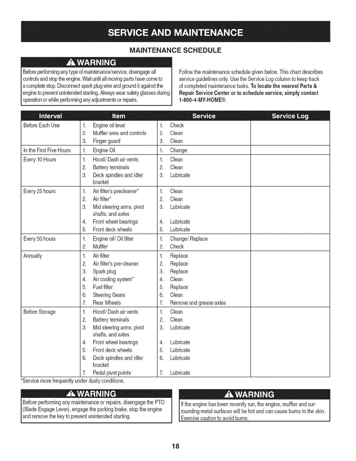
Followthe maintenanceschedulegivenbelow.Thischartdescribes
serviceguidelinesonly.Usethe ServiceLogcolumnto keeptrack
of completedmaintenancetasks.To locate the nearest Parts&
Repair Service Centeror to scheduleservice,simplycontact
1-800-4-MY-HOME®.
BeforeEachUse
In the FirstFiveHours
Every10Hours
Every25 hours
Every50 hours
Annually
BeforeStorage
1. Engineoil level
2. Mufflerareaandcontrols
3. Fingerguard
1. EngineOil
1. Hood/Dashairvents
2. Batteryterminals
3. Deckspindlesand idler
bracket
1. Air filter'sprecleaner*
2. Air filter*
3. Midsteeringarms,pivot
shafts,andaxles
4. Frontwheelbearings
5. Frontdeckwheels
1. Engineoil/Oil filter
2. Muffler
1. Air filter
2. Air filter'spre-cleaner
3. Sparkplug
4. Air coolingsystem*
5. Fuelfilter
6. SteeringGears
7. RearWheels
1. Hood/Dashairvents
2. Batteryterminals
3. Midsteeringarms,pivot
shafts,andaxles
4. Frontwheelbearings
5. Frontdeckwheels
6. Deckspindlesand idler
bracket
7. Pedalpivotpoints
1. Check
2. Clean
3. Clean
1. Change
1. Clean
2. Clean
3. Lubricate
1. Clean
2. Clean
3. Lubricate
4. Lubricate
5. Lubricate
1. Change/Replace
2. Check
1. Replace
2. Replace
3. Replace
4. Clean
5. Replace
6. Clean
7. Removeandgreaseaxles
1. Clean
2. Clean
3. Lubricate
4. Lubricate
5. Lubricate
6. Lubricate
7. Lubricate
*Servicemorefrequentlyunderdustyconditions.
Beforeperformingany maintenanceor repairs,disengagethe PTO
(BladeEngageLever),engagethe parkingbrake,stopthe engine
and removethe keyto preventunintendedstarting.
Ifthe enginehasbeen recentlyrun,the engine,mufflerandsur-
roundingmetalsurfaceswill behotand cancauseburnsto the skin.
Exercisecautionto avoidburns.
18
ENGINE MAINTENANCE
Checking the Engine Oil
Onlyuse highqualitydetergentoil ratedwithAPIserviceclassification
SF,SG,SH,or SJ, Selectthe oil's SAEviscositygradeaccordingto
the expectedoperatingtemperature.Followthe chartbelow.
Althoughmulti-viscosityoils (5W20,10W30,etc.)improvestarting
in coldweather,theywill resultinincreasedoil consumptionwhen
usedabove32°E Checkyour engineoillevelmorefrequentlyto avoid
possibleenginedamagefromrunninglowonoil.
('_older _ 32°F _War me'_r
Oil Viscosity Chart
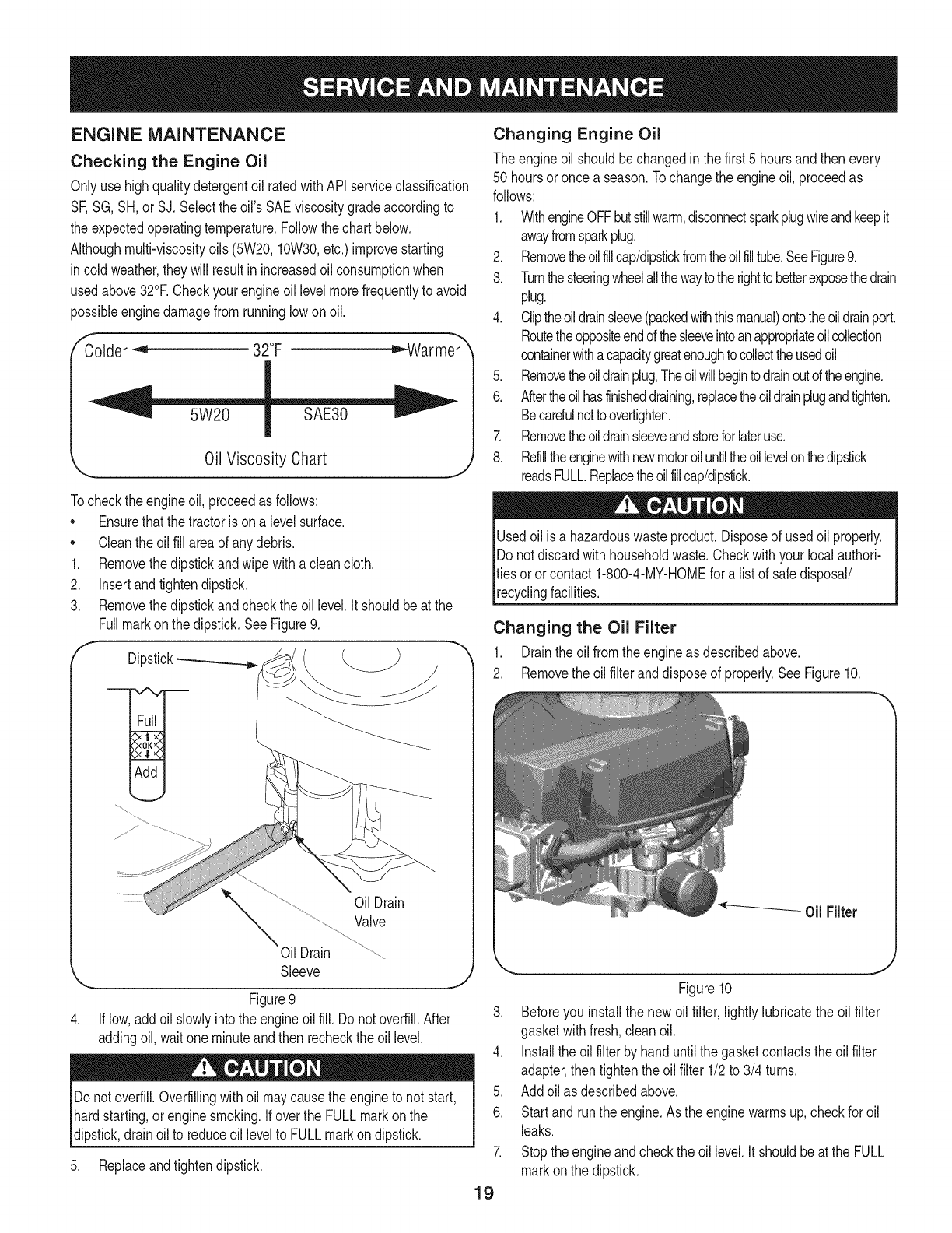
Tocheckthe engineoil, proceedas follows:
• Ensurethatthe tractoris ona levelsurface.
• Cleantheoil fill areaof anydebris.
1. Removethedipstickandwipe withaclean cloth.
2. Insertandtightendipstick.
3. Removethedipstickandcheckthe oil level.It shouldbeat the
Fullmarkonthe dipstick.SeeFigure9.
fDipstick-_
OilDrain
Valve
Oil Drain
Sleeve J
Figure9
If low,addoil slowlyintothe engineoilfill. Do notoverfill.After
addingoil, waitone minuteand then recheckthe oil level.
Donotoverfill.Overfillingwithoil maycausethe engineto not start,
hardstarting,orenginesmoking.If overthe FULLmarkonthe
dipstick,drainoil to reduceoil levelto FULLmarkondipstick.
5. Replaceandtightendipstick.
Changing Engine Oil
The engineoil shouldbechangedinthe first 5 hoursand thenevery
50 hoursoronce a season.Tochangethe engineoil, proceedas
follows:
1. WithengineOFFbutstillwarm,disconnectsparkplugwireandkeepit
awayfromsparkplug.
2. Removetheoilfillcap/dipstickfromtheoilfilltube.SeeFigure9.
3. Turnthesteeringwheelallthewaytothe righttobetterexposethedrain
plug.
4. Cliptheoildrainsleeve(packedwiththismanual)ontotheoildrainport.
Routetheoppositeendofthesleeveintoanappropriateoilcollection
containerwithacapacitygreatenoughtocollecttheusedoil.
5. Removetheoildrainplug,Theoilwillbegintodrainoutoftheengine.
6. Aftertheoilhasfinisheddraining,replacetheoildrainplugandtighten.
Becarefulnottoovertighten.
7. Removetheoildrainsleeveandstoreforlateruse.
8. Refilltheenginewithnewmotoroiluntiltheoillevelonthedipstick
readsFULL.Replacetheoilfillcap/dipstick.
Usedoil is a hazardouswasteproduct.Disposeof usedoil properly.
Do notdiscardwithhouseholdwaste.Checkwithyour localauthori-
ties oror contact1-800-4-MY-HOMEfor alist of safedisposal/
recyclingfacilities.
Changing the Oil Filter
1. Drainthe oil fromthe engineas describedabove.
2. Removethe oilfilteranddisposeof properly.See Figure10.
Figure10
3. Beforeyou installthe newoil filter, lightlylubricatethe oil filter
gasketwithfresh,cleanoil.
4. Installthe oil filterbyhanduntilthe gasketcontactstheoil filter
adapter,then tightenthe oilfilter 1/2to 3/4 turns.
5. Addoil as describedabove.
6. Startand runthe engine.Asthe enginewarmsup,checkfor oil
leaks.
7. Stoptheengineandcheckthe oil level.It shouldbeat the FULL
markonthe dipstick.
19
Fuel Filter Air Cleaner
Gasolineand itsvaporsareextremelyflammableandexplosive.Fire
orexplosioncan causesevereburnsor death.
•Keepgasolineawayfromsparks,openflames,pilotlights,heat,
andotherignitionsources.
•Checkfuel lines,tank,cap,andfittingsfrequentlyforcracksor
leaks.Replaceif necessary.
•Beforereplacingthe fuelfilter,drainthe fueltankas perthe
instructionsbelow.
•Do notdrainfuel whenthe engineishot.Allowthe engine
adequatetimeto cool. Drainfuel intoan approvedcontainer
outdoors,awayfromopenflame.
•Drainanylargevolumeof fuelfromthe tankby disconnectingthe
fuel linefromthe in-linefuelfilterneartheengine.
•Removethe fuel linefromthe In-lineside (sidetowardsthe fuel
tank)of thefuel filter.
•Replacementpartsmustbethe sameand installedin the same
positionas theoriginalparts.
•Iffuel spills,waituntil itevaporatesbeforestartingengine.
•Beforereplacingthe fuelfilter,drainthe fueltank. Otherwisefuel
can leakout andcausea fireor explosion.
To Drainthe fuel:
1. Locatethefuelfilter,whichis routedonthe leftsideofthe engine
betweenthe fueltankandthe carburetor,andmaybeattachedto
theenginewitha tie strap.Cutthetie strap,ifpresent,then pinch
thein-lineclamponthefuelfilterwitha pairof pliers,slidethe
clampupthefuelline.Pullthe fuellinefreefromthefilterandplace
theopenendof the lineintoanapprovedcontainerto drainthefuel.
Tochangethe fuel filter:
1. Usepliersto squeezethe tabsonthe otherclamp(theout-line
sideof the fuel filter),thenslidethe clampawayfromthe fuel filter.
Twistandpull the fuellineoff of the fuelfilter.SeeFigure11.
Clamp Fuel
Line
Tab
Figure11
.J
2. Checkthe fuel linesfor cracksor leaks.Replaceif necessary.
3. Replacethe fuel filterwithan originalequipmentreplacement
filter.Call1-800-4-MY-HOME®to purchasethe originalequip-
mentreplacementfilter.
4. Securethe fuel lineswiththe clamps.
Iffilters,or coversare notinstalledcorrectlyseriousinjuryordeath
could resultfrombackfire.Do notattemptto startthe enginewith
themremoved.
Donot use pressurizedair or solventsto cleanthe aircleaner
cartridge.
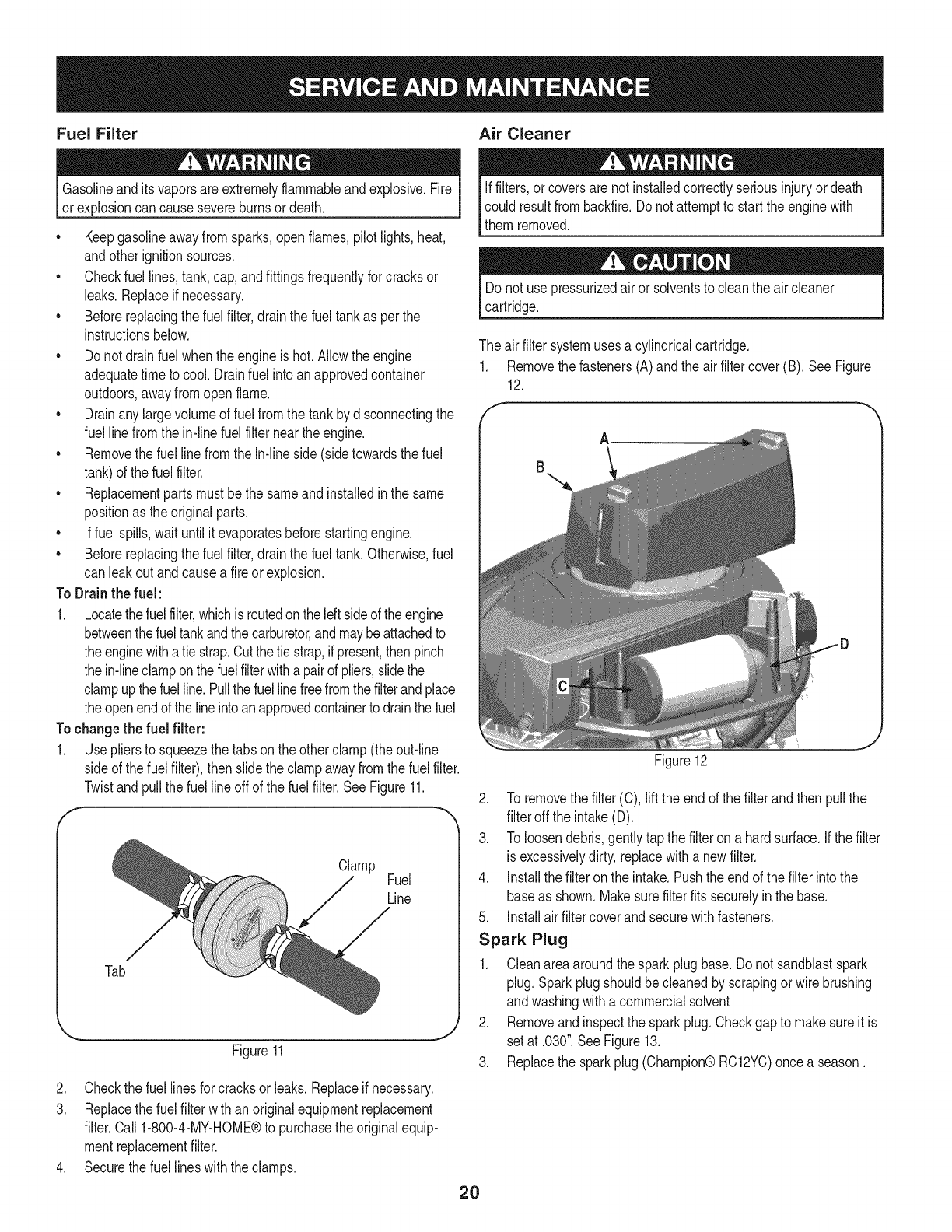
The airfiltersystemusesa cylindricalcartridge.
1. Removethe fasteners(A) andthe airfiltercover (B). SeeFigure
12.
A
Figure12
2. To removethe filter(C),liftthe endof the filterandthen pullthe
filteroff the intake(D).
3. To loosendebris,gentlytapthe filteron a hardsurface,if thefilter
is excessivelydirty,replacewitha newfilter.
4. installthe filteronthe intake.Pushthe endof the filterintothe
baseas shown.Makesurefilterfits securelyin the base.
5. installairfiltercoverandsecurewithfasteners.
Spark Plug
1. Cleanareaaroundthe sparkplugbase.Donot sandblastspark
plug. Sparkplugshouldbecleanedby scrapingor wirebrushing
andwashingwitha commercialsolvent
2. Removeandinspectthe sparkplug.Checkgapto makesureitis
setat .030".SeeFigure13.
3. Replacethe sparkplug(Champion®RC12YC)oncea season.
2O
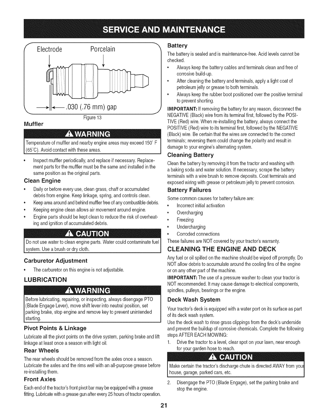
fElectrode Porcelain
J
Temperatureof mufflerand nearbyengineareasmayexceed 150° F
(65°0).Avoidcontactwiththeseareas.
• inspectmufflerperiodically,and replaceif necessary.Replace-
mentpartsfor the mufflermustbethe sameand installedin the
samepositionas the originalparts.
Clean Engine
•Dailyor beforeeveryuse,cleangrass,chaff oraccumulated
debrisfromengine.Keeplinkage,spring,andcontrolsclean.
• Keepareaaroundandbehindmufflerfreeofanycombustibledebris.
• Keepingenginecleanallowsair movementaroundengine.
• Enginepartsshouldbe keptcleanto reducethe riskof overheat-
ingandignitionof accumulateddebris.
Do notuse waterto cleanengineparts.Watercouldcontaminatefuel
system.Usea brushordry cloth.
Carburetor Adjustment
• Thecarburetoron thisengineis not adjustable.
LUBRICATION
Beforelubricating,repairing,or inspecting,alwaysdisengagePTO
(BladeEngageLever),moveshift leverinto neutralposition,set
parkingbrake,stopengineand removekeyto preventunintended
starting.
Pivot Points &Linkage
Lubricateall the pivotpointson thedrive system,parkingbrakeand lift
linkageat leastoncea seasonwithlightoil.
Rear Wheels
Battery
The batteryis sealedandis maintenance-free.Acidlevelscannotbe
checked.
• Alwayskeepthe batterycablesandterminalscleanandfree of
corrosivebuild-up.
• Aftercleaningthe batteryandterminals,applya lightcoatof
petroleumjelly orgreaseto bothterminals.
• Alwayskeepthe rubberbootpositionedoverthe positiveterminal
to preventshorting.
IMPORTANT: if removingthe batteryfor any reason,disconnectthe
NEGATIVE(Black)wirefromitsterminalfirst,followedby the POSI-
TIVE(Red)wire.When re-installingthe battery,alwaysconnectthe
POSITIVE(Red)wire to its terminalfirst,followedbythe NEGATIVE
(Black)wire.Becertainthatthe wiresareconnectedto the correct
terminals;reversingthemcouldchangethe polarityandresult in
damageto yourengine'salternatingsystem.
Cleaning Battery
Cleanthe batteryby removingit fromthe tractorandwashingwith
a bakingsodaandwatersolution.Ifnecessary,scrapethe battery
terminalswitha wirebrushto removedeposits.Coatterminalsand
exposedwiringwithgreaseor petroleumjelly to preventcorrosion.
Battery Failures
Somecommoncausesfor batteryfailureare:
• incorrectinitialactivation
• Overcharging
• Freezing
• Undercharging
• Corrodedconnections
Thesefailuresare NOTcoveredbyyourtractor'swarranty.
CLEANING THE ENGINE AND DECK
Any fuelor oil spilledon the machineshouldbewipedoff promptly.Do
NOTallowdebristo accumulatearoundthe coolingfinsof the engine
or onany otherpartof the machine.
IMPORTANT: The useof a pressurewasherto cleanyourtractoris
NOTrecommended.Itmaycausedamageto electricalcomponents,
spindles,pulleys,bearingsor the engine.
Deck Wash System
Yourtractor'sdeckis equippedwitha waterporton itssurfaceas part
of itsdeckwashsystem.
Usethe deckwashto rinsegrassclippingsfromthe deck'sunderside
and preventthe buildupof corrosivechemicals.Completethe following
stepsAFTEREACHMOWING:
1. Drivethe tractorto a level,clear spoton yourlawn,nearenough
for yourgardenhoseto reach.
The rearwheelsshouldbe removedfromthe axlesoncea season.
Lubricatethe axlesandthe rimswell withanall-purposegreasebefore
re-installingthem.
Front Axles
Eachendof thetractor'sfrontpivotbarmaybeequippedwithagrease
fitting.Lubricatewithagreasegunafterevery25hoursoftractoroperation.
Makecertainthe tractor'sdischargechuteis directedAWAYfromyoul
house,garage,parkedcars,etc.
2. Disengagethe PTO(BladeEngage),setthe parkingbrakeand
stopthe engine.
21
3. Threadthe hosecoupler(packagedwithyourtractor'sOperator's
Manual)ontothe endof your gardenhose.
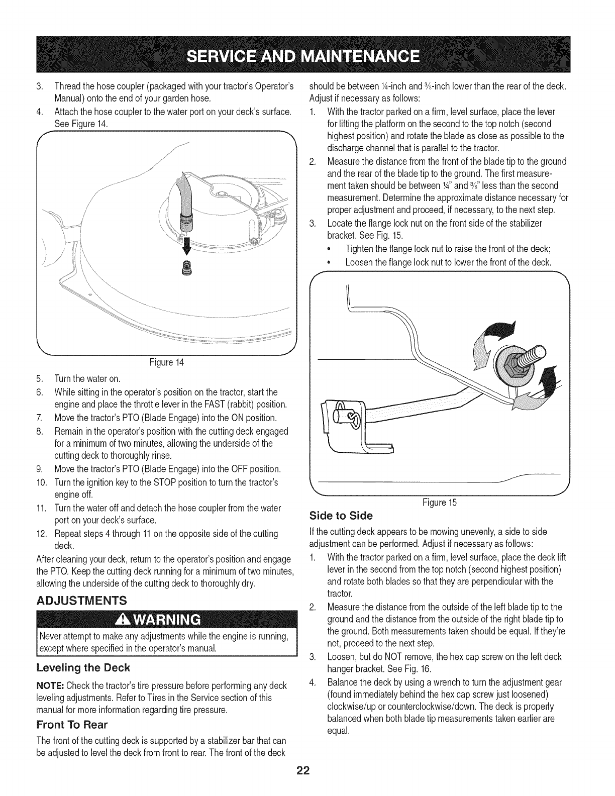
4. Attachthe hosecouplerto the waterport onyourdeck'ssurface.
SeeFigure14.
J
j,
/
f
J _; .......... ........
8
Figure14
5. Turnthe wateron.
6. Whilesittinginthe operator'spositiononthe tractor,startthe
engineandplacethe throttleleverinthe FAST(rabbit)position.
7. Movethe tractor'sPTO(BladeEngage)intothe ON position.
8. Remaininthe operator'spositionwiththecuttingdeckengaged
for a minimumof two minutes,allowingthe undersideof the
cuttingdeckto thoroughlyrinse.
9. Movethe tractor'sPTO(BladeEngage)intothe OFFposition.
10. Turnthe ignitionkeytothe STOPpositionto turnthe tractor's
engineoff.
11. Turnthe wateroff anddetachthe hosecouplerfromthe water
port onyourdeck'ssurface.
12. Repeatsteps4through11on the oppositeside of the cutting
deck.
Aftercleaningyourdeck, returnto the operator'spositionandengage
the PTO.Keepthe cuttingdeckrunningfor a minimumof twominutes,
allowingthe undersideof thecuttingdeckto thoroughlydry.
ADJUSTMENTS
Neverattemptto makeanyadjustmentswhilethe engineis running,
exceptwherespecifiedin the operator'smanual.
Leveling the Deck
NOTE: Checkthe tractor'stire pressurebeforeperforminganydeck
levelingadjustments.Referto Tiresinthe Servicesectionof this
manualfor moreinformationregardingtire pressure.
Front To Rear
Thefrontof the cuttingdeckis supportedby a stabilizerbarthatcan
beadjustedto levelthe deckfromfrontto rear.Thefrontof the deck
shouldbe between_A-inchand3A-inchlowerthanthe rearof the deck.
Adjustif necessaryas follows:
1. Withthe tractorparkedona firm, levelsurface,placethe lever
for liftingthe platformonthe secondto the top notch(second
highestposition)and rotatethe bladeas closeas possibleto the
dischargechannelthatis parallelto the tractor.
2. Measurethedistancefromthe frontof the bladetip to the ground
andthe rearof the bladetip to theground.Thefirst measure-
menttakenshouldbe between_A"and3A"lessthanthe second
measurement.Determinethe approximatedistancenecessaryfor
properadjustmentandproceed,if necessary,to the nextstep.
3. Locatethe flangelocknut onthe frontsideof the stabilizer
bracket.SeeFig.15.
•Tightenthe flangelocknut to raisethe frontof the deck;
Loosentheflangelock nutto lowerthe frontof thedeck.
o
f
f__
Side to Side
Figure15 J
Ifthe cuttingdeckappearsto be mowingunevenly,a sideto side
adjustmentcan beperformed.Adjustif necessaryas follows:
1. Withthe tractorparkedona firm, levelsurface,placethe decklift
leverin the secondfromthe top notch(secondhighestposition)
and rotatebothbladessothat theyare perpendicularwiththe
tractor.
2. Measurethedistancefromthe outsideof the left bladetip to the
groundandthe distancefromthe outsideof the rightbladetip to
the ground.Bothmeasurementstakenshouldbeequal.Ifthey're
not, proceedto the nextstep.
3. Loosen,but do NOTremove,the hexcap screwonthe leftdeck
hangerbracket.SeeFig. 16.
4. Balancethedeckby usinga wrenchto turn theadjustmentgear
(foundimmediatelybehindthehex cap screwjust loosened)
clockwise/uporcounterclockwise/down.Thedeckis properly
balancedwhen bothbladetip measurementstakenearlierare
equal.
22
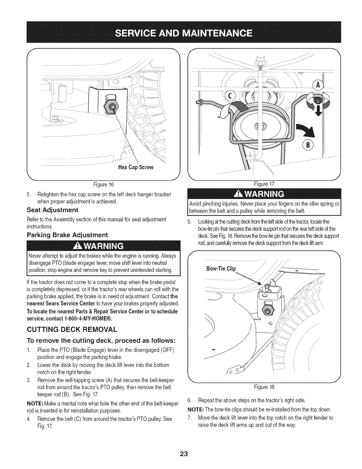
He× Cap Screw
'_._. j
Figure16
5. Retightenthe hexcap screwon the left deckhangerbracket
whenproperadjustmentis achieved.
Seat Adjustment
Referto the Assemblysectionof thismanualfor seatadjustment
instructions.
Parking Brake Adjustment
Neverattemptto adjustthe brakeswhiletheengineis running.Always
disengagePTO(bladeengage)lever,moveshiftleverintoneutral
position,stopengineandremovekeyto preventunintendedstarting.
If thetractordoes notcometo acompletestopwhenthe brakepedal
is completelydepressed,or if the tractor'srearwheelscan rollwiththe
parkingbrakeapplied,the brakeis in needof adjustment.Contactthe
nearest Sears Service Centerto haveyourbrakesproperlyadjusted.
Tolocatethe nearest Parts& Repair ServiceCenteror to schedule
service,contact 1-800-4-MY-HOME®.
CUTTING DECK REMOVAL
To remove the cutting deck, proceed as follows:
1. Placethe PTO(Blade Engage)leverin the disengaged(OFF)
positionandengagethe parkingbrake.
2. Lowerthe deck by movingthe deck lift lever intothe bottom
notchon the rightfender.
3. Removetheself-tappingscrew(A) thatsecuresthe belt-keeper
rodfromaroundthe tractor'sPTOpulley,thenremovethe belt
keeperrod(B). SeeFig. 17.
NOTE: Makea mentalnotewhatholethe otherendof the belt-keeper
rodisinsertedinfor reinstallationpurposes.
4. Removethebelt (C) fromaroundthetractor'sPTOpulley.See
Fig.17.
Figure17
Avoidpinchinginjuries.Neverplaceyourfingerson the idlerspringor
betweenthe beltanda pulleywhileremovingthe belt.
Lookingatthecuttingdeckfromtheleftsideofthetractor,locatethe
bow-tiepinthatsecuresthedecksupportrodontherearIdtsidedthe
deck.SeeFig.18.Removethebow-tiepinthatsecuresthedecksupport
rod,andcarefullyremovethedecksupportfromthedeckliftarm.
Figure18
6. Repeatthe abovestepson the tractor'srightside.
NOTE: The bow-tieclipsshouldbe re-installedfromthe top down.
7. Movethe decklift leverintothe top notchon the rightfenderto
raisethe decklift armsupandout of the way.
23
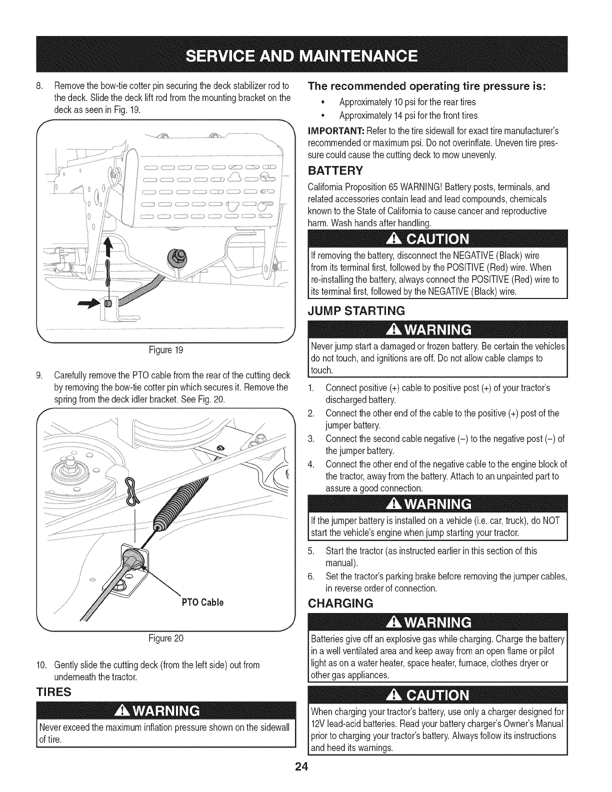
.Removethe bow-tiecotterpin securingthe deckstabilizerrodto
thedeck. Slidethe decklift rodfrom the mountingbracketon the
deckas seenin Fig.19.
..........._'_¢& _ .......................................
Figure19
.
f
Carefullyremovethe PTOcablefromthe rearof the cuttingdeck
by removingthe bow-tiecotterpinwhichsecuresit. Removethe
springfromthe deckidlerbracket.SeeFig.20.
PTOCable
Figure20
10. Gentlyslidethe cuttingdeck(fromthe left side)out from
underneaththe tractor.
TIRES
Neverexceedthe maximuminflationpressureshownonthe sidewall
of tire.
The recommended operating tire pressure is:
• Approximately10psi for the reartires
• Approximately14psi for the fronttires
IMPORTANT: Referto the tire sidewallfor exacttire manufacturer's
recommendedormaximumpsi.Donot overinflate.Uneventire pres-
surecould causethe cuttingdeckto mowunevenly.
BATTERY
CaliforniaProposition65 WARNING!Batteryposts,terminals,and
relatedaccessoriescontainleadandleadcompounds,chemicals
knownto the Stateof Californiato causecancerandreproductive
harm.Washhandsafter handling.
If removingthe battery,disconnectthe NEGATIVE(Black)wire
fromits terminalfirst,followedbythe POSITIVE(Red) wire.When
re-installingthe battery,alwaysconnectthe POSITIVE(Red)wire to
Its termna f rst,fo owedby the NEGATVE (Back) w re.
JUMP STARTING
Neverjump starta damagedorfrozenbattery.Becertainthevehicles
do not touch,and ignitionsareoff. Do notallowcable clampsto
touch.
1. Connectpositive(+)cableto positivepost(+)of yourtractor's
dischargedbattery.
2. Connecttheotherendof thecableto the positive(+)postof the
jumperbattery.
3. Connectthesecondcable negative(-) to the negativepost(-) of
the jumperbattery.
4. Connecttheotherendof thenegativecableto the engineblockof
the tractor,awayfromthe battery.Attachto anunpaintedpartto
assurea goodconnection.
Ifthejumper batteryis installedona vehicle(i.e.car,truck),do NOT
startthe vehicle'senginewhenjump startingyourtractor.
5. Startthe tractor(as instructedearlierin thissectionof this
manual).
6. Set the tractor'sparkingbrakebeforeremovingthejumpercables,
in reverseorderof connection.
CHARGING
give offan explosivegas whilecharging.Chargethe batteryI
Batteries
ina wellventilatedareaandkeepawayfroman openflameor pilot
ght as ona waterheater,spaceheater,furnace,c othesdryeror |
othergas appliances. J
Whenchargingyourtractor'sbattery,useonlya chargerdesignedfor I
12Vlead-acidbatteries.Readyourbatterychargers Owners Manual
priorto chargingyourtractors battery.Alwaysfollowits instructions I
land heed ts warnngs. j
24
If yourtractorhasnot beenputinto usefor anextendedperiodof time,
chargethe batteryas follows:
1. Setyour batterychargerto delivera maxof 10amperes.
If yourbatterychargeris automatic,chargethe batteryuntilthe
chargerindicatesthatchargingis complete.Ifthe chargeris not
automatic,chargefor nofewerthaneight hours.
FUSE
One20AMPfuseis installedin yourtractor'swiringharnessto protect
the tractor'selectricalsystemfromdamagecausedbyexcessive
amperage.
If theelectricalsystemdoesnot function,or yourtractor'senginewill
not crank,first checkto be certainthatthe fusehasnot blown.It can
befoundat the rear of the unit,underneaththefenderlocatedby the
battery.
Alwaysusea fusewiththe sameamperagecapacityfor replacement.
CUTTING BLADES
Shutthe engineoff andremoveignitionkeybeforeremovingthe
cuttingblade(s)for sharpeningor replacement.Protectyourhands
by usingheavygloveswhengraspingthe blade.
Periodicallyinspectthe bladeand/or spindlefor cracksordamage,
especiallyafter you'vestrucka foreignobject. Donot operatethe
machineuntil damagedcomponentsare replaced.
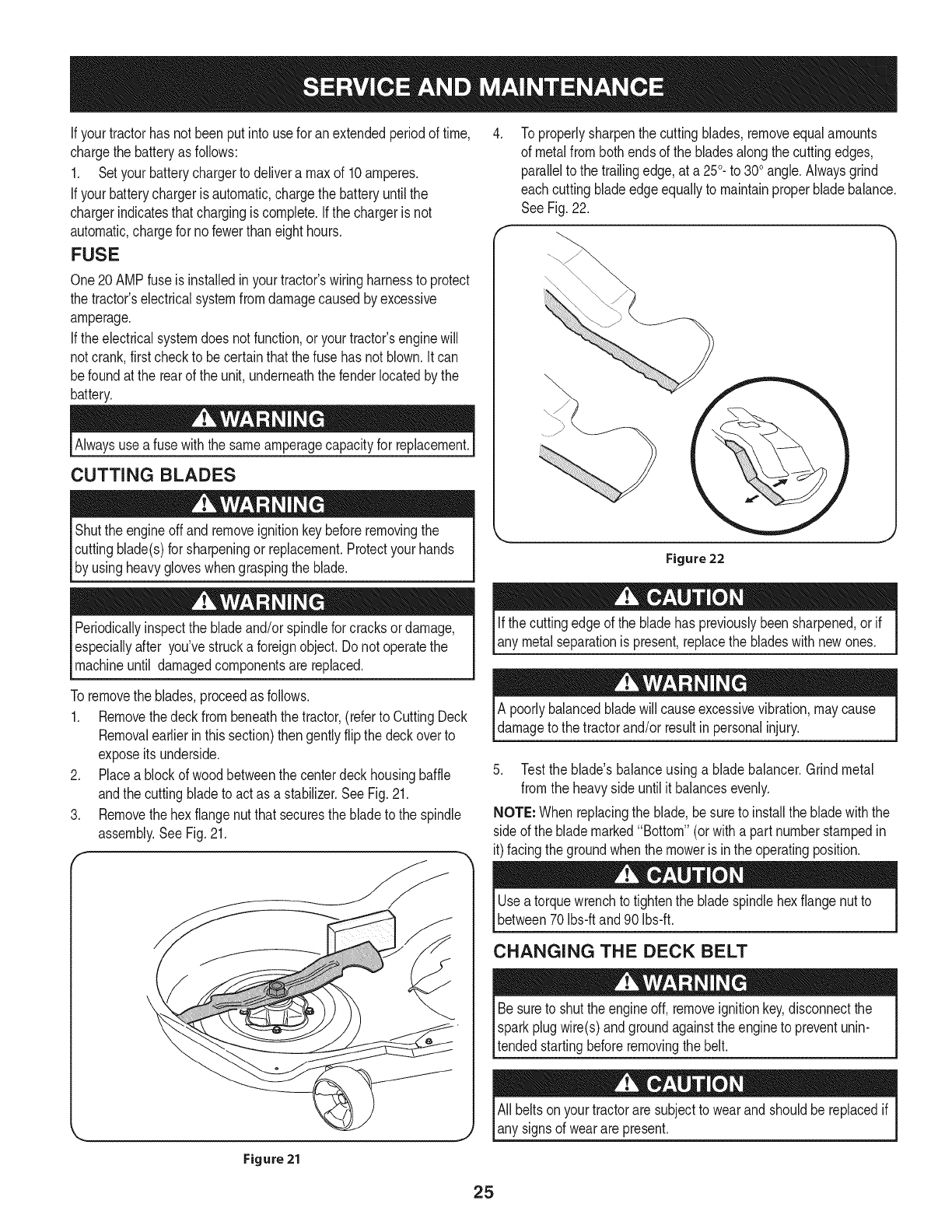
To properlysharpenthe cuttingblades,removeequalamounts
of metalfrombothendsof the bladesalongthe cuttingedges,
parallelto the trailingedge,at a250.to 300angle.Alwaysgrind
eachcutting bladeedgeequallyto maintainproperbladebalance.
SeeFig.22.
Figure 22
Ifthe cuttingedgeof the bladehas previouslybeensharpened,or if
any metalseparationis present,replacethe bladeswith newones.
Toremovethe blades,proceedas follows.
1. Removethedeckfrombeneaththe tractor,(referto CuttingDeck
Removalearlierinthis section)thengentlyflip thedeckoverto
exposeitsunderside.
2. Placea blockof woodbetweenthe centerdeckhousingbaffle
andthe cuttingbladeto actas a stabilizer.SeeFig.21.
3. Removethehex flangenutthat securesthe bladeto the spindle
assembly.SeeFig.21.
A poorlybalancedbladewill causeexcessivevibration,maycause
damageto the tractorand/or resultin personalinjury.
5. Testthe blade'sbalanceusinga bladebalancer.Grindmetal
from the heavyside untilit balancesevenly.
NOTE: Whenreplacingthe blade,be sureto installthe bladewiththe
sideof the blademarked"Bottom"(orwitha part numberstampedin
it)facingthe groundwhenthe moweris inthe operatingposition.
Figure 21
Usea torquewrenchto tightenthe bladespindlehexflangenut to
between70Ibs-ftand 90Ibs-ft.
CHANGING THE DECK BELT
Besureto shutthe engineoff, removeignitionkey,disconnectthe
Isparkplugwire(s)andgroundagainstthe engineto preventunin-
ltended startingbeforeremovingthe belt.
All beltsonyourtractoraresubjectto wearandshouldbereplacedif
any signsof wearare present.
25
IMPORTANT: The V-beltfoundon yourtractoris speciallydesigned
to engageanddisengagesafely.A substitute(non-OEM)V-beltcan
bedangerousby notdisengagingcompletely.Fora properworking
machine,useidenticalequipmentbeltsas listedin the partspagesof
thisOperator'sManual.
Tochangeor replacethe deckbelt onyourtractor,proceedas follows:
1. Removethe deckas instructedearlierinthis section.
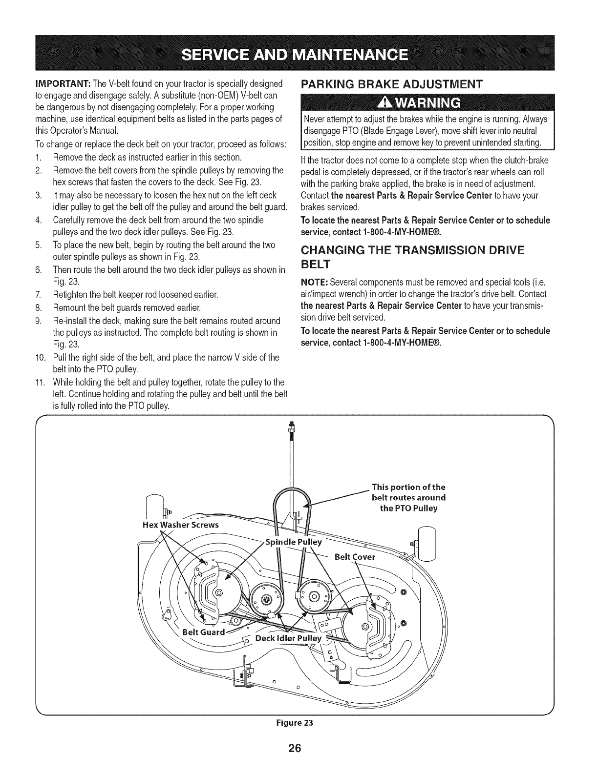
2. Removethe beltcoversfromthe spindlepulleysby removingthe
hexscrewsthatfastenthecoversto the deck.SeeFig.23.
3. It mayalso benecessaryto loosenthe hex nuton the leftdeck
idlerpulleyto getthe belt offthe pulleyandaroundthe beltguard.
4. Carefullyremovethe deckbeltfromaroundthe twospindle
pulleysandthetwo deckidlerpulleys,SeeFig,23,
5. Toplacethe newbelt,beginby routingthe belt aroundthe two
outerspindlepulleysas shownin Fig,23,
6. Thenroutethe beltaroundthe twodeckidlerpulleysas shownin
Fig.23,
7. Retightenthe belt keeperrodloosenedearlier.
8. Remountthebelt guardsremovedearlier,
9. Re-installthedeck, makingsurethe belt remainsroutedaround
the pulleysas instructed.Thecompletebelt routingis shownin
Fig,23.
10. Pullthe rightside ofthe belt,and placethe narrowVside of the
belt intothe PTOpulley.
11. Whileholdingthe beltandpulleytogether,rotatethepulleyto the
left. Continueholdingandrotatingthe pulleyand beltuntilthe belt
is fullyrolledintothe PTOpulley.
PARKING BRAKE ADJUSTMENT
Neverattemptto adjustthe brakeswhiletheengineis running.Always
disengagePTO(BladeEngageLever),moveshiftleverintoneutral
position,stopengineandremovekeyto preventunintendedstarting.
Ifthe tractordoesnot cometo a completestopwhenthe clutch-brake
pedalis completelydepressed,or if the tractor'srearwheelscan roll
withthe parkingbrakeapplied,the brakeis inneedof adjustment.
Contactthe nearest Parts & RepairService Centerto haveyour
brakesserviced,
To locatethe nearestParts& RepairServiceCenteror to schedule
service, contact 1-800-4-MY-HOME®.
CHANGING THE TRANSMISSION DRIVE
BELT
NOTE: Severalcomponentsmust beremovedandspecialtools(i.e.
air/impactwrench)inorderto changethetractor'sdrivebelt.Contact
the nearest Parts & Repair Service Centerto haveyourtransmis-
sion drivebelt serviced.
Tolocatethe nearestParts& RepairServiceCenteror to schedule
service, contact 1-800-4-MY-HOME®.
Hex Washer Screws
Belt Cover
This portion of the
belt routes around
the PTO Pulley
BeltGuard
_ _oo Deckidier Pu,,ey
Figure 23
26
Neverstorelawntractorwithfuel intankindoorsor in poorly
ventilatedareaswherefuel fumesmayreachan openflame,spark,
orpilot lightas ona furnace,waterheater,clothesdryer,or gas
appliance.
PREPARING THE ENGINE
IMPORTANT:Fuelleftin thefuel tankduringwarmweatherdeterio-
ratesandwill causeseriousstartingproblems.
To preventgumdepositsfromforminginsidethe engine'scarburetor
andcausingpossiblemalfunctionof theengine,thefuel systemmust
be eithercompletelyemptied,orthe gasolinemustbe treatedwitha
stabilizerto preventdeterioration.
1. Ifusingafuel stabilizer:
a. Readthe productmanufacturer'sinstructionsandrecom-
mendations.
b. Addto clean,freshgasolinethe correctamountof stabilizer
for the capacityof the fuel system.
c. Fillthe fueltankwithtreatedfuel andrunthe enginefor 2-3
minutesto get stabilizedfuel intothe carburetor.
2. Ifemptyingthe fuel system:
a. Donot drainfuel whenthe engineis hot.Allowthe engine
adequatetimeto cool.Drainfuelinto anapprovedcontainer
outdoors,awayfromopenflame.
b. Drainany largevolumeof fuel fromthetank bydisconnect-
ing thefuel linefromthe in-linefuel filternearthe engine.
Seethe completeinstructionsfor DrainingThe Fuellaterin
this section.
Gasolineis extremelyflammableandcan beexplosiveundercertain
conditions.Draingasolinebeforestoringthe equipmentfor extended
periods.Drainfuel only intoanapprovedcontaineroutdoors,away
froman openflame.Allowengineto cool.Extinguishcigarettes,
cigars,pipes,andothersourcesof ignitionpriorto drainingfuel.
Storegasolineinan approvedcontainerinsafelocation.
c. Reconnectthe fuel lineandrunthe engineuntil it startsto
falter,thenuse thechoketo keeptheenginerunninguntilall
fuel in thecarburetorhas beenexhausted.
d. Disconnectthefuel lineanddrainany remaininggasoline
fromthe system.
DRAiNiNG THE FUEL
1. Locatethe fuel filter,whichis locatedonthe leftsideof the
engine,andmaybe attachedto the enginewitha tie strap.
2. Cutthe tie strap,if present,then pinchthe in-lineclamponthe
fuel filterwitha pairof pliers,slidethe clampupthe fuel line.
3. Pullthe fuel linefreefromthe filterandplacethe openendof the
lineintoanapprovedcontainerto drainthe fuel.
PREPARING THE LAWN TRACTOR
1. Cleanandlubricatetractorthoroughlyas describedinthe lubrica-
tion instructions.
2. Donot usea pressurewasheror gardenhoseto cleanyour unit.
3. Storemowerin a dry,cleanarea. Do notstore nextto corrosive
materials,suchas fertilizer.
Gasolineis a toxicsubstance.Disposeof gasolineproperly.Contact
your localauthoritiesfor approveddisposalmethods.
3. Removethe sparkplugandpourone(1)ounceof engineoil
throughthe sparkplugholeintothe cylinder.Cranktheengine
severaltimesto distributethe oil. Replacethe sparkplug.
27
Enginefailsto start
Enginerunserratically
1. PTO/BladeEngageleverengaged.
2. Parkingbrakenotengaged.
3. Sparkplugwire(s)disconnected.
4. Throttle/Chokecontrollevernot incorrect
startingposition.
5. Chokenotactivated
6. Fueltankempty,or stalefuel.
7. BIockedfuelline.
8. Faultysparkplug(s).
9. Engineflooded.
10. BlownFuse(s)
1. UnitrunningwithCHOKEactivated.
2. Sparkplugwire(s)loose.
3. Blockedfuel lineor stalefuel.
4. Ventingas cap plugged.
5. Waterordirt infuel system.
6. Dirtyair cleaner.
Engineoverheats 1. Engineoillevellow. 1.
2. Airflowrestricted. 2.
Enginehesitatesat highRPM 1. Sparkpluggaptoo close. 1.
Engineidles rough 1. Sparkplugfouled,faultyor gaptoo wide. 1.
2. Dirtyair cleaner. 2.
Excessivevibration
Mowerwill not mulchgrass
Unevencut
1. Cuttingbladelooseor unbalanced.
2. Damagedor bentcuttingblade.
1. Enginespeedtoo low.
2. Wetgrass.
3. Excessivelyhighgrass.
4. Dullblade.
1. Decknot leveledproperly.
2. Dullblade.
3. Uneventire pressure.
1. Placeleverindisengaged(OFF)position.
2. Engageparkingbrake.
3. Connectwire(s)to sparkplug(s).
4. PlaceThrottle/Chokeleverintothe FASTposition.
5. MovetheThrottle/Chokeleverintothe Choke
position.
6. Filltankwithclean,fresh(lessthan30 daysold) gas.
7. Replacethe fuel lineandreplacefuel filter.
8. Clean,adjustgapor replaceplug(s).
9. Crankenginewiththrottlein FASTposition.
10. ReplaceFuse(s)
1. Deactivatethe CHOKE.
2. Connectsparkplugwire(s).
3. Replacethe fuel line;fill tankwithclean,fresh
gasolineandreplacefuel filter.
4. Clearventor replacecap if damaged.
5. Drainfuel tank. Refillwithclean,freshgasoline.
6. Replaceair cleanerpaperelementor cleanfoam
pre-cleaner,if equipped.
Fillcrankcasewith properamountandweightof oil.
Cleangrassclippingsanddebrisfromaroundthe
engine'scoolingfinsandhousing.
Removesparkplugandresetthe gap.
Replacesparkplug.Set pluggap.
Replaceair cleanerelementand/orclean pre-
cleaner.
1. Tightenbladeandspindle.
2. Replaceblade.
1. Placethrottlein FAST(rabbit)position.
2. Do notmulchwhengrassis wet.
3. Mowonce at a highcuttingheight,then mowagain
at desiredheightor makea narrowercuttingswath.
4. Sharpenor replaceblade.
1. Performside-to-sidedeckadjustment.
2. Sharpenor replaceblade.
3. Checktire pressureinallfour tires.
NEED MORE HELP?
Find this and aLLyour other product manuals online,
Get answers from our team of home experts.
Get a personalized maintenance plan for your home,
Find information and tools to help with home projects.
_o #At 1o ye b:_ Sea_s
28
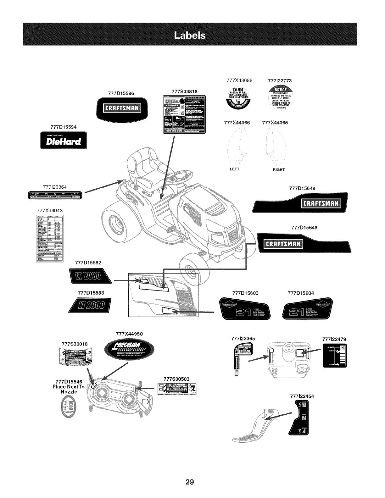
777D15594
777D15596 777S33818
777X43688 777122773
DONOT
USE EN5OR FUEL STEERINGWHEEL
CONTAININGMORE MOUNTINGHARDWARE
THAN 10% ETHANOL UNDER CAR BEFORE
OPERATIONSECURE
STEERING WHEEL TO
SHAFT ACCORDING
TO MANUAL
777X44366 777X44365
LEFT RIGHT
777123364
777)(44943
777D15582
777D15649
777D15648
777D15583 777D15603 777D15604
777S30018
777X44950 777123365 777122479
777D15546
Place Next To
Nozzle
777S30503
777122454
29
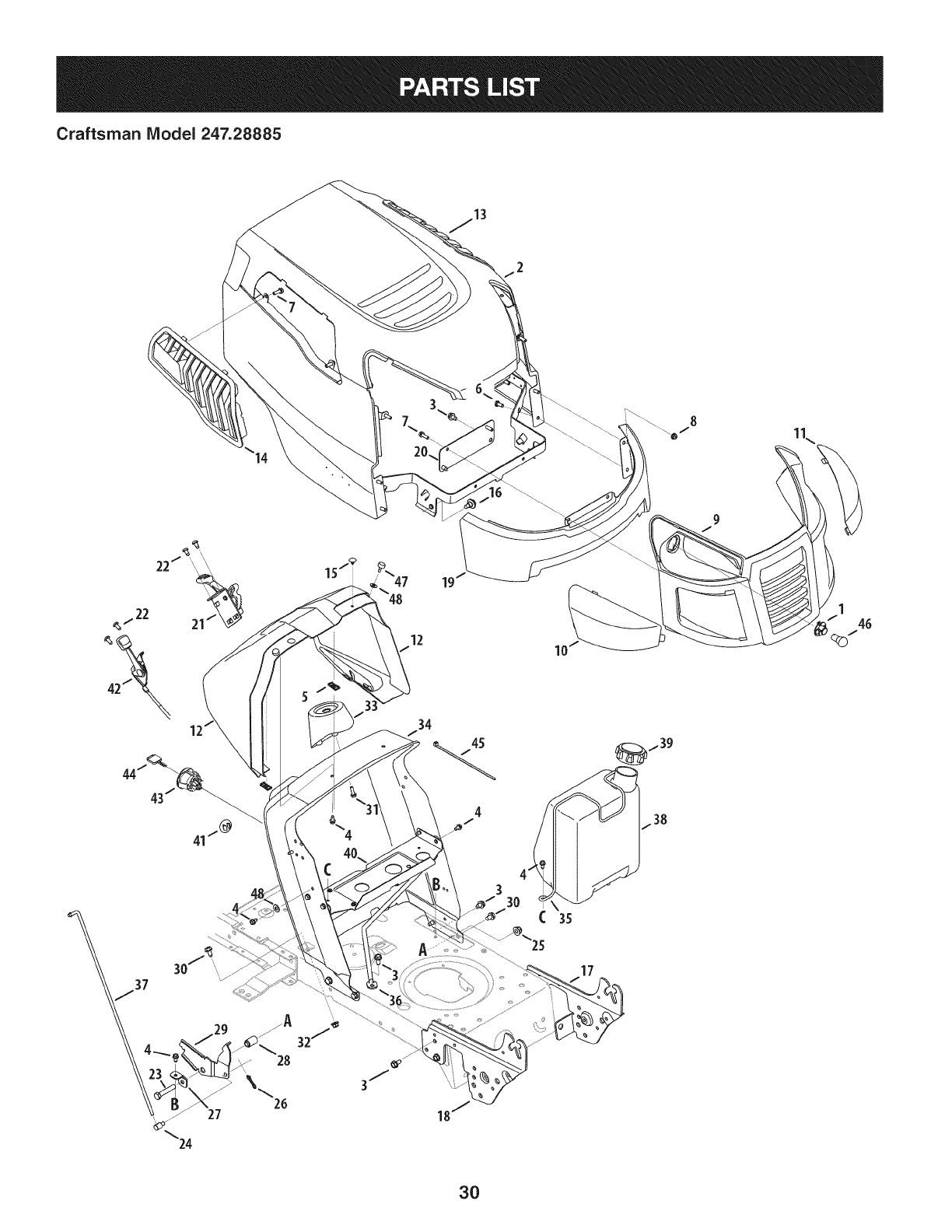
Craftsman IViodel 247.28885
12 10
17
3O
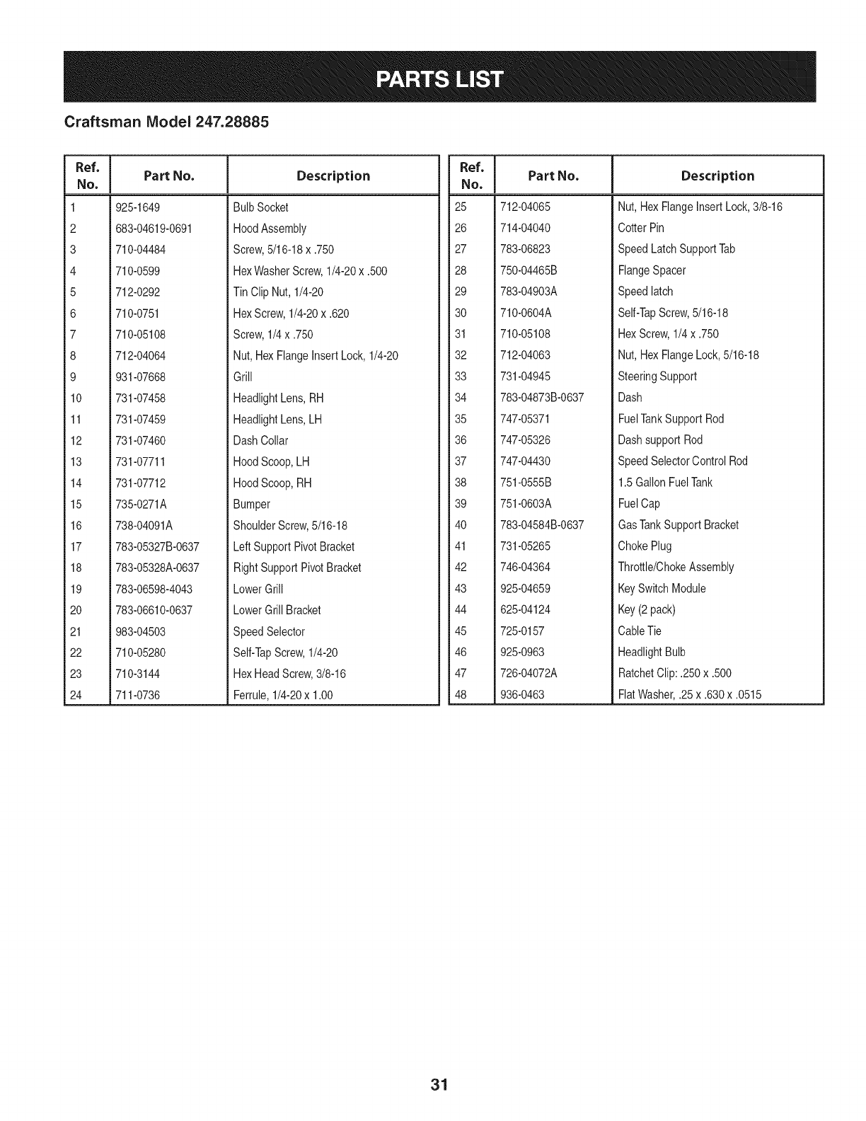
Craftsman Model 247.28885
Ref. I
No,
1 925-1649
2 683-04619-0691
3 710-04484
4 710-0599
5 712-0292
6 710-0751
7 710-05108
8 712-04064
9 931-07668
10 731-07458
11 731-07459
12 731-07460
13 731-07711
14 731-07712
15 735-0271A
16 738-04091A
17 783-05327B-0637
18 783-05328A-0637
19 783-06598-4043
20 783-06610-0637
21 983-04503
22 710-05280
23 710-3144
24 711-0736
Part No. Description
BulbSocket
HoodAssembly
Screw,5/16-18x .750
HexWasherScrew,1/4-20x .500
Tin Clip Nut, 1/4-20
HexScrew,1/4-20x .620
Screw,1/4x .750
Nut,HexFlangeInsertLock,1/4-20
Grill
HeadlightLens,RH
HeadlightLens,LH
DashCollar
HoodScoop,LH
HoodScoop,RH
Bumper
ShoulderScrew,5/16-18
LeftSupportPivotBracket
RightSupportPivotBracket
LowerGrill
LowerGrillBracket
SpeedSelector
Self-TapScrew,1/4-20
HexHeadScrew,3/8-16
Ferrule,1/4-20x 1.00
Ref. I
No,
25 712-04065
26 714-04040
27 783-06823
28 750-04465B
29 783-04903A
30 710-0604A
31 710-05108
32 712-04063
33 731-04945
34 783-04873B-0637
35 747-05371
36 747-05326
37 747-04430
38 751-0555B
39 751-0603A
40 783-04584B-0637
41 731-05265
42 746-04364
43 925-04659
44 625-04124
45 725-0157
46 925-0963
47 726-04072A
48 936-0463
Part No. Description
Nut, HexFlangeInsertLock,3/8-16
CotterPin
SpeedLatchSupportTab
FlangeSpacer
Speedlatch
Self-TapScrew,5/16-18
HexScrew,1/4x .750
Nut, HexFlangeLock,5/16-18
SteeringSupport
Dash
FuelTankSupportRod
Dashsupport Rod
SpeedSelectorControl Rod
1.5GallonFuelTank
FuelCap
GasTankSupportBracket
ChokePlug
Throttle/ChokeAssembly
KeySwitchModule
Key(2 pack)
CableTie
HeadlightBulb
RatchetClip:.250x .500
FlatWasher,.25x .630x .0515
31
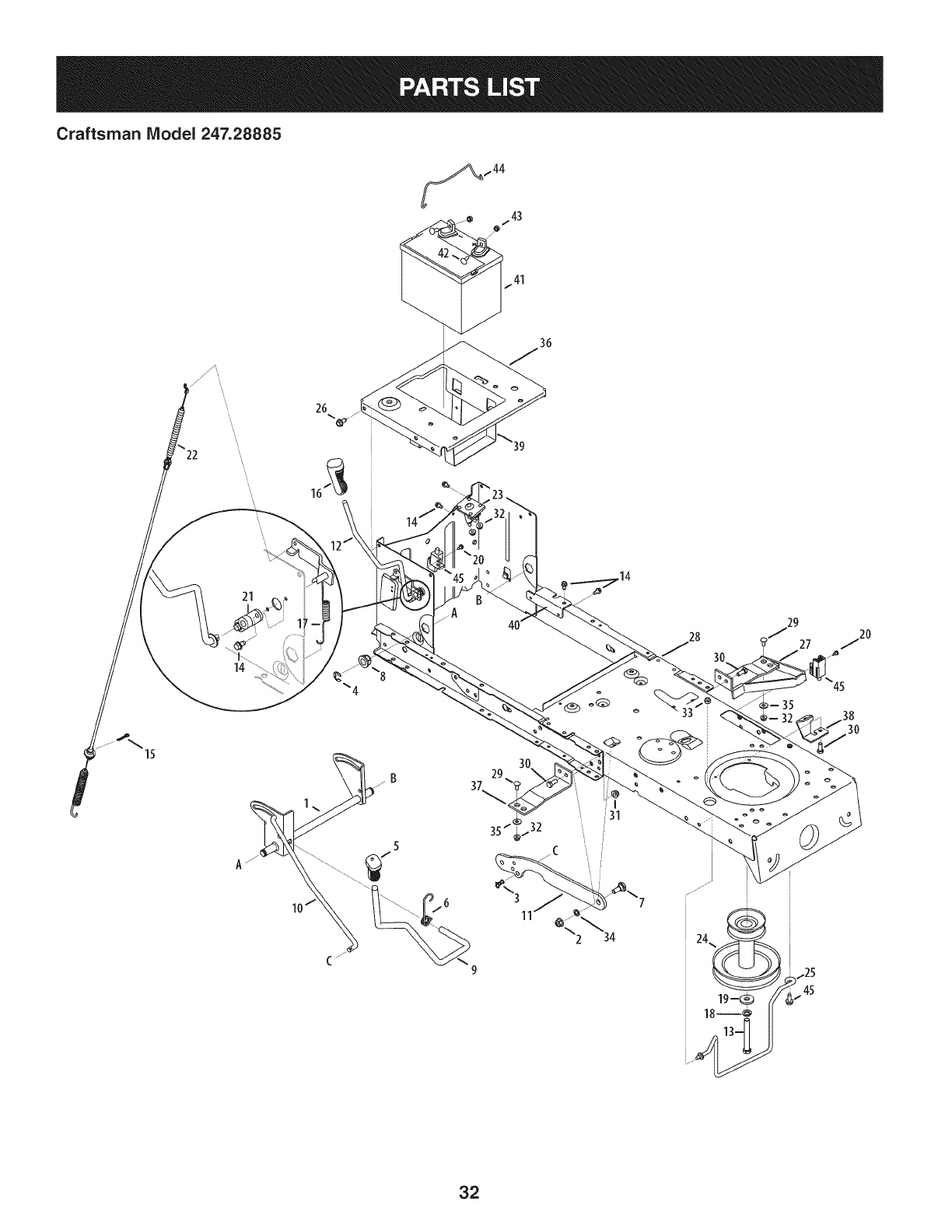
Craftsman IViodel 247.28885
15
21
14
37 29
45
30
32
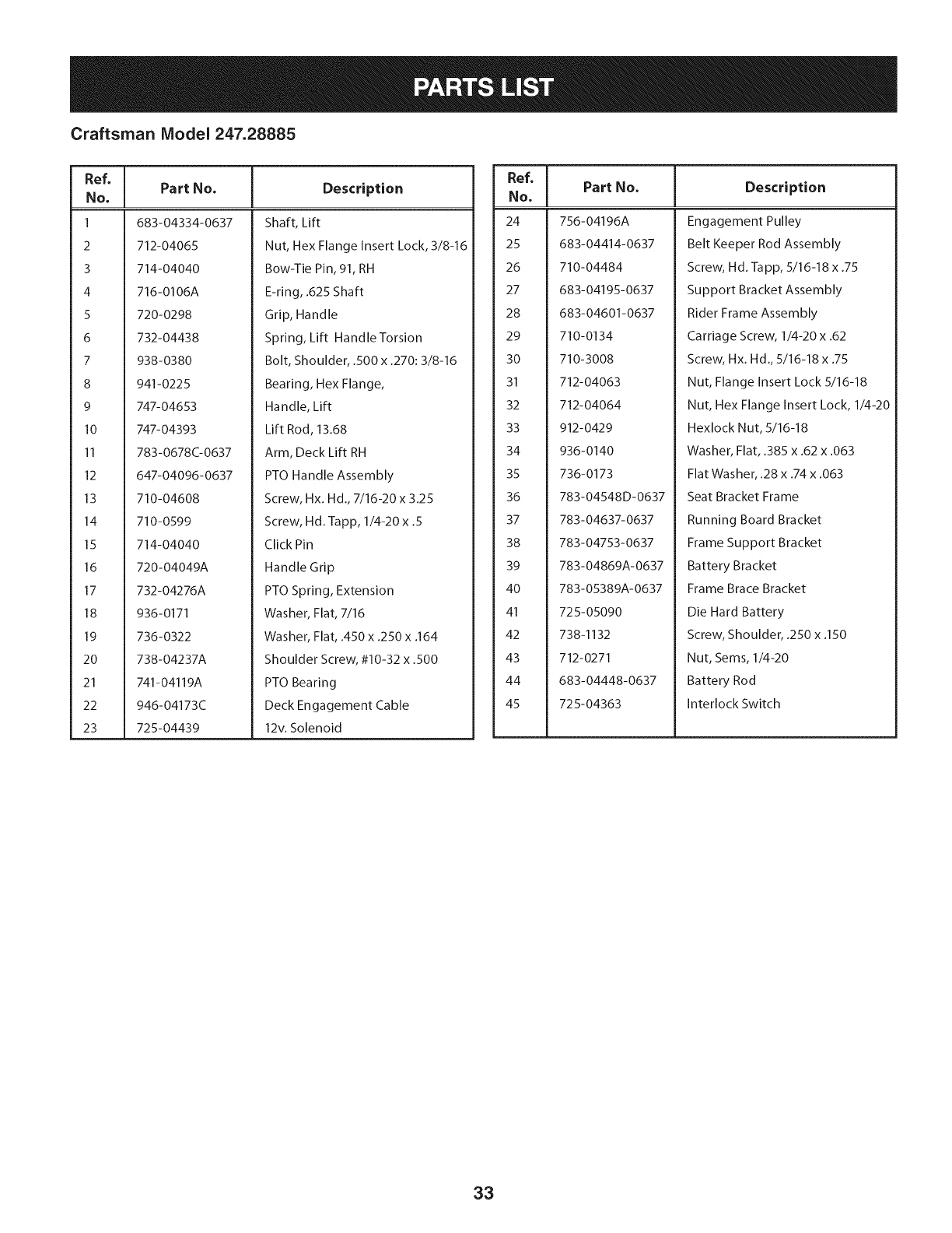
Craftsman Model 247.28885
Ref, ]
No,
1 683-04334-0637
2 712-04065
3 714-04040
4 716-0106A
5 720-0298
6 732-04438
7 938-0380
8 941-0225
9 747-04653
10 747-04393
11 783-0678C-0637
12 647-04096-0637
13 710-04608
14 710-0599
15 714-04040
16 720-04049A
17 732-04276A
18 936-0171
19 736-0322
20 738-04237A
21 741-04119A
22 946-04173C
23 725-04439
Part No, Description
Shaft, Lift
Nut, Hex Flange Insert Lock, 3/8-16
Bow-Tie Pin, 91, RH
E-ring, .625 Shaft
Grip, Handle
Spring, Lift Handle Torsion
Bolt, Shoulder, .500 x .270:3/8-16
Bearing, Hex Flange,
Handle, Lift
Lift Rod, 13.68
Arm, Deck Lift RH
PTO Handle Assembly
Screw, Hx. Hd., 7/16-20 x 3.25
Screw, Hd. lapp, 1/4-20 x .5
Click Pin
Handle Grip
PTO Spring, Extension
Washer, Flat, 7/16
Washer, Flat, .450 x .250 x .164
Shoulder Screw, #10-32 x .500
PTO Bearing
Deck Engagement Cable
12v. Solenoid
Ref, I
No,
24 756-04196A
25 683-04414-0637
26 710-04484
27 683-04195-0637
28 683-04601-0637
29 710-0134
30 710-3008
31 712-04063
32 712-04064
33 912-0429
34 936-0140
35 736-0173
36 783-04548D-0637
37 783-04637-0637
38 783-04753-0637
39 783-04869A-0637
40 783-05389A-0637
41 725-05090
42 738-1132
43 712-0271
44 683-04448-0637
45 725-04363
Part No, Description
Engagement Pulley
Belt Keeper Rod Assembly
Screw, Hd. Tapp, 5/16-18 x .75
Support Bracket Assembly
Rider Frame Assembly
Carriage Screw, 1/4-20 x .62
Screw, Hx. Hd., 5/16-18 x .75
Nut, Flange Insert Lock 5/16-18
Nut, Hex Flange Insert Lock, 1/4-20
Hexlock Nut, 5/16-18
Washer, Flat, .385 x .62 x .063
Flat Washer, .28 x .74 x .063
Seat Bracket Frame
Running Board Bracket
Frame Support Bracket
Battery Bracket
Frame Brace Bracket
Die Hard Battery
Screw, Shoulder, .250 x .150
Nut, Seres, 1/4-20
Battery Rod
Interlock Switch
33
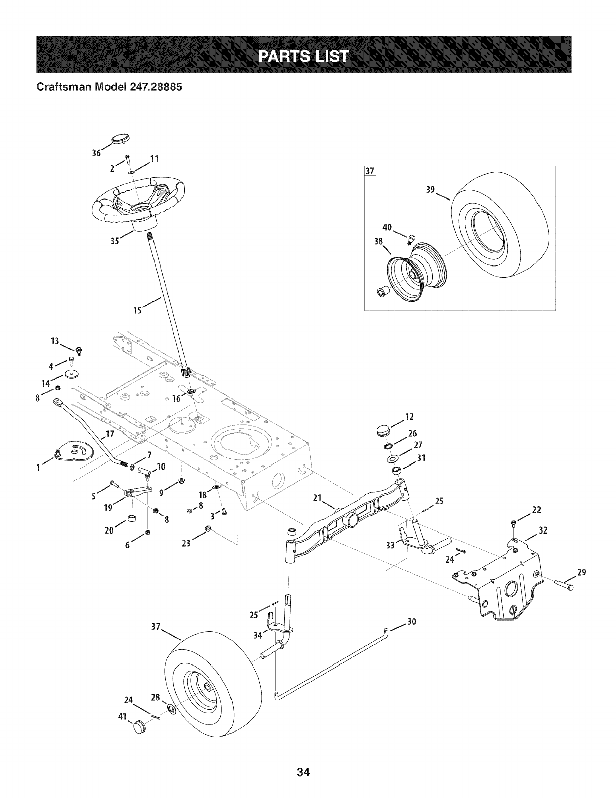
Craftsman IViodel 247.28885
24 28
41
24_ ..........
29
34
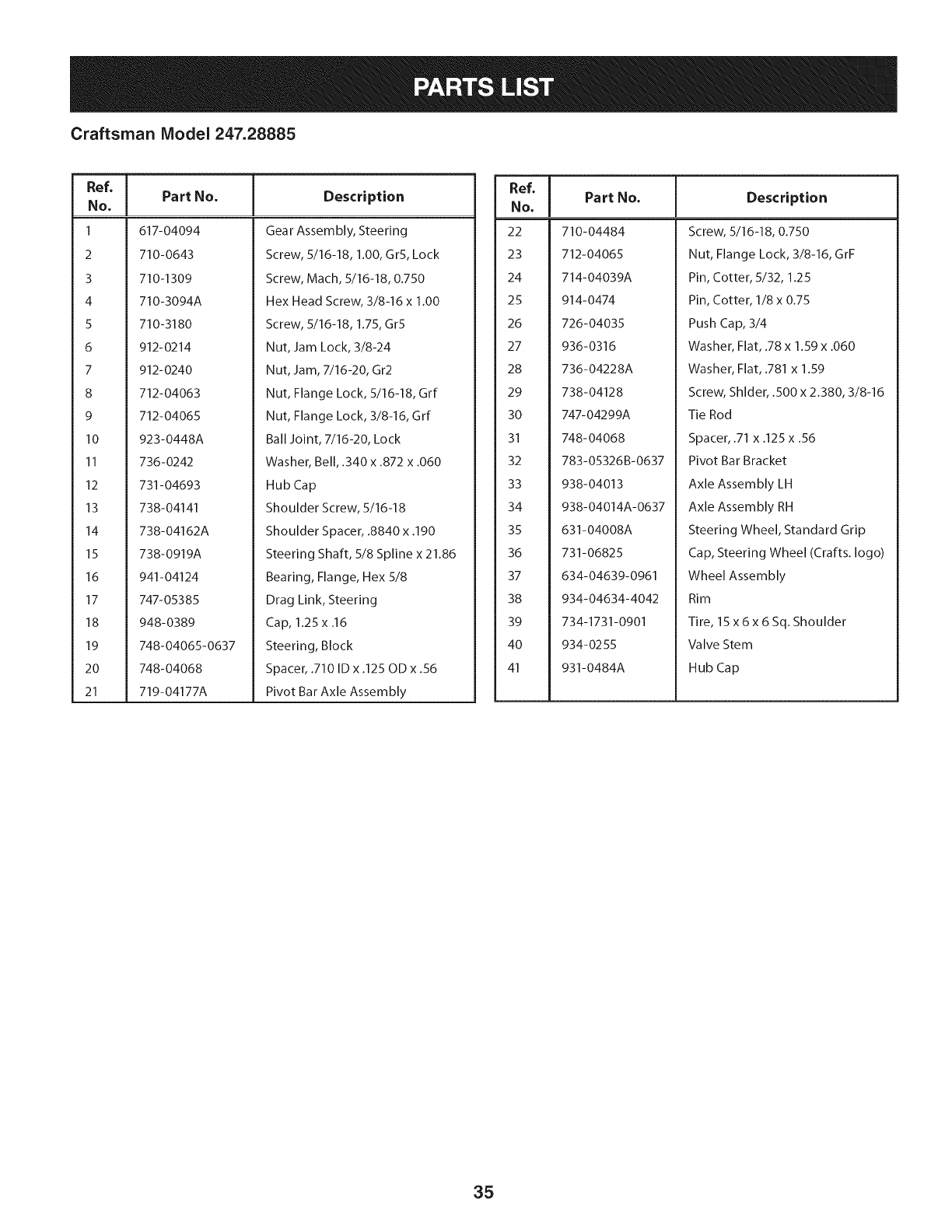
Craftsman Model 247.28885
Ref, I
No,
1 617-04094
2 710-0643
3 710-1309
4 710-3094A
5 710-3180
6 912-0214
7 912-0240
8 712-04063
9 712-04065
10 923-0448A
11 736-0242
12 731-04693
13 738-04141
14 738-04162A
15 738-0919A
16 941-04124
17 747- 05385
18 948-0389
19 748-04065-0637
20 748-04068
21 719-04177A
Part No. Description
Gear Assembly, Steering
Screw, 5/16-18, 1.00, GrS, Lock
Screw, Mach, 5/16-18, 0.750
Hex Head Screw, 3/8-16 x 1.00
Screw, 5/16-18, 1.75, Gr5
Nut, Jam Lock, 3/8-24
Nut, Jam, 7/16-20, Gr2
Nut, Flange Lock, 5/16-18, Grf
Nut, Flange Lock, 3/8-16, Grf
Ball Joint, 7/16-20, Lock
Washer, Bell, .340 x .872 x .060
Hub Cap
Shoulder Screw, 5/16-18
Shoulder Spacer, .8840 x .190
Steering Shaft, 5/8 Spline x 21.86
Bearing, Flange, Hex 5/8
Drag Link, Steering
Cap, 1.25 x .16
Steering, Block
Spacer, .710 ID x .125 OD x .56
Pivot Bar Axle Assembly
Ref, I
No,
22 710-04484
23 712-04065
24 714-04039A
25 914-0474
26 726-04035
27 936-0316
28 736-04228A
29 738-04128
30 747-04299A
31 748-04068
32 783-05326B-0637
33 938-04013
34 938-04014A-0637
35 631-04008A
36 731-06825
37 634-04639-0961
38 934-04634-4042
39 734-1731-0901
40 934-0255
41 931-0484A
Part No. Description
Screw, 5/16-18, 0.750
Nut, Flange Lock, 3/8-16, GrF
Pin, Cotter, 5/32, 1.25
Pin, Cotter, 1/8 x 0.75
Push Cap, 3/4
Washer, Flat, .78 x 1.59 x .060
Washer, Flat, .781 x 1.59
Screw, Shlder, .500 x 2.380, 3/8-16
Tie Rod
Spacer, .71 x .125 x .56
Pivot Bar Bracket
Axle Assembly LH
Axle Assembly RH
Steering Wheel, Standard Grip
Cap, Steering Wheel (Crafts. logo)
Wheel Assembly
Rim
Tire, 15 x6x 6 Sq. Shoulder
Valve Stem
Hub Cap
35
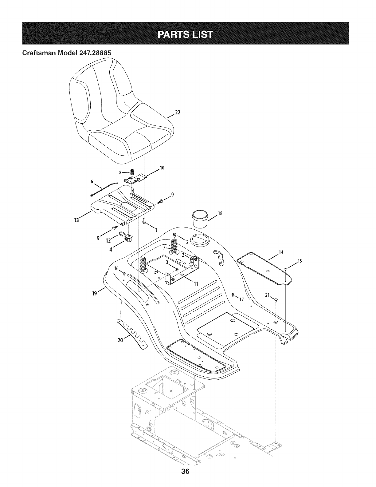
Craftsman Model 247.28885
13
\
11
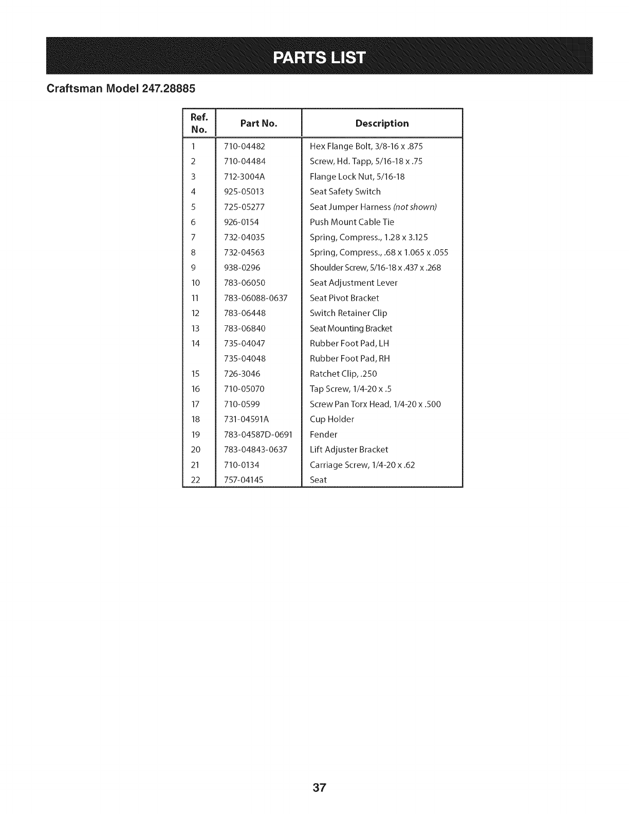
Craftsman Model 247.28885
Ref, [
No,
I 710-04482
2 710-04484
3 712-3004A
4 925-05013
5 725-05277
6 926-0154
7 732-04035
8 732-04563
9 938-0296
10 783-06050
11 783-06088-0637
12 783-06448
13 783-06840
14 735-04047
735-04048
15 726-3046
16 710-05070
17 710-0599
18 731-04591A
19 783-04587D-0691
20 783-04843-0637
21 710-0134
22 757-04145
Part No. Description
Hex Flange Bolt, 3/8-16 x .875
Screw, Hd.-lapp, 5/16-18 x .75
Flange Lock Nut, 5/16-18
Seat Safety Switch
Seat Jumper Harness (notshown)
Push Mount Cable Tie
Spring, Compress., 1.28 x 3.125
Spring, Compress., .68 x 1.065 x .055
Shoulder Screw, 5/16-18 x .437 x .268
Seat Adjustment Lever
Seat Pivot Bracket
Switch Retainer Clip
Seat Mounting Bracket
Rubber Foot Pad, LH
Rubber Foot Pad, RH
Ratchet Clip, .250
Tap Screw, 1/4-20 x .5
Screw Pan Torx Head, 1/4-20 x .500
Cup Holder
Fender
Lift Adjuster Bracket
Carriage Screw, 1/4-20 x .62
Seat
37
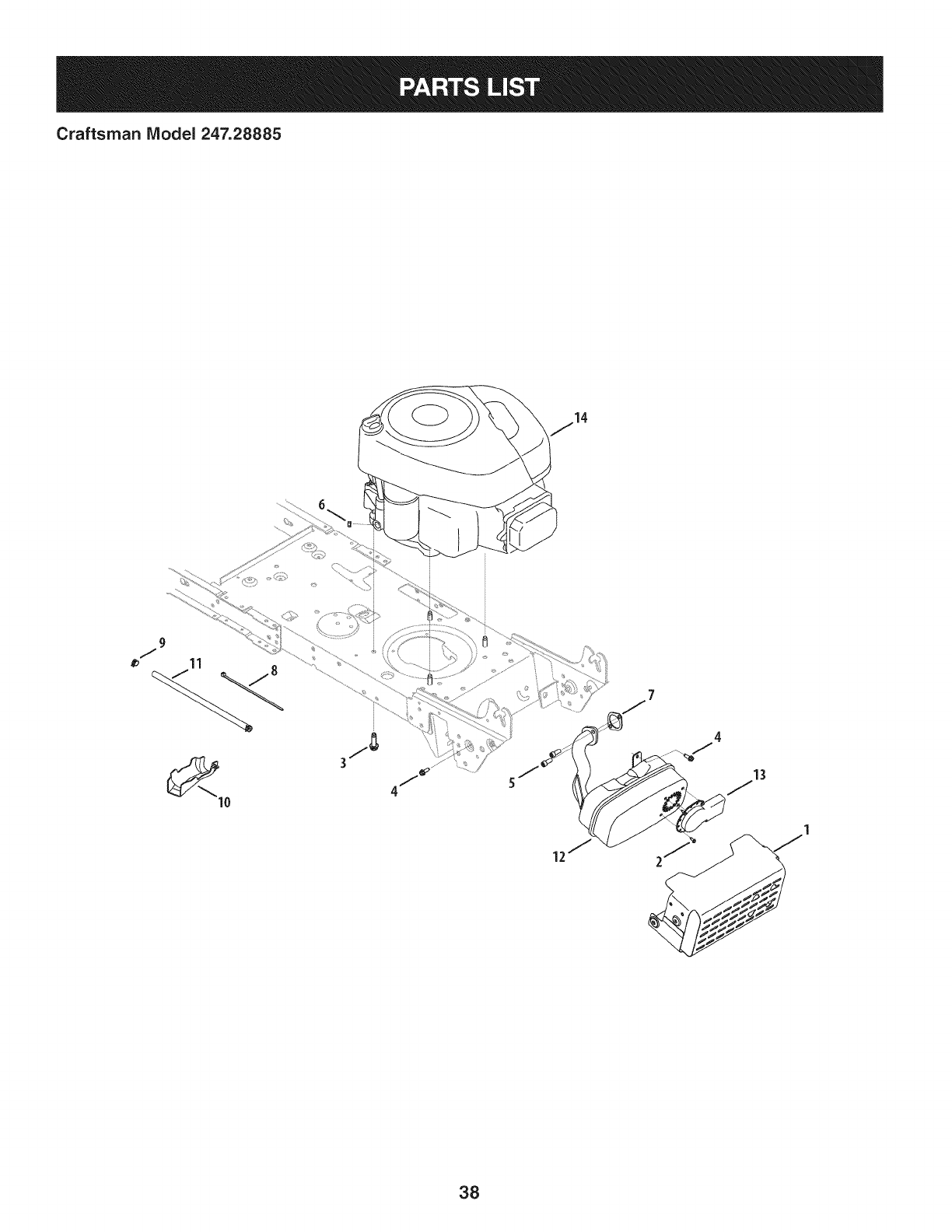
Craftsman IViodel 247.28885
13
38
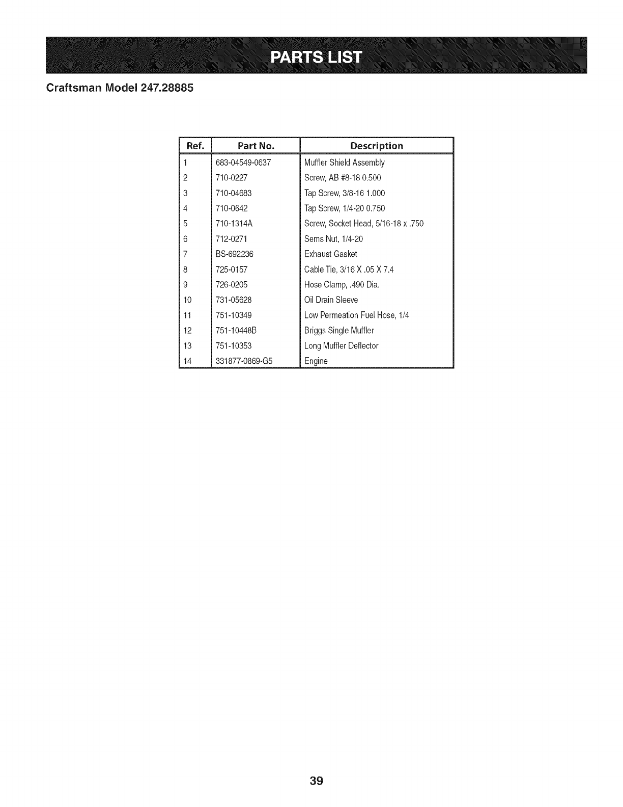
Craftsman IViodel 247.28885
I
Ref. IPart No.
1 683-04549-0637
2 710-0227
3 710-04683
4 710-0642
5 710-1314A
6 712-0271
7 BS-692236
8 725-0157
9 726-0205
10 731-05628
11 751-10349
12 751-10448B
13 751-10353
14 331877-0869-G5
Descriptien
MufflerShieldAssembly
Screw,AB #8-180.500
TapScrew,3/8-16 1.000
TapScrew,1/4-200.750
Screw,SocketHead,5/16-18x .750
Sems Nut, 1/4-20
ExhaustGasket
CableTie,3/16 X .05X 7.4
HoseClamp,.490 Dia.
Oil DrainSleeve
LowPermeationFuelHose,1/4
BriggsSingleMuffler
LongMufflerDeflector
Engine
39
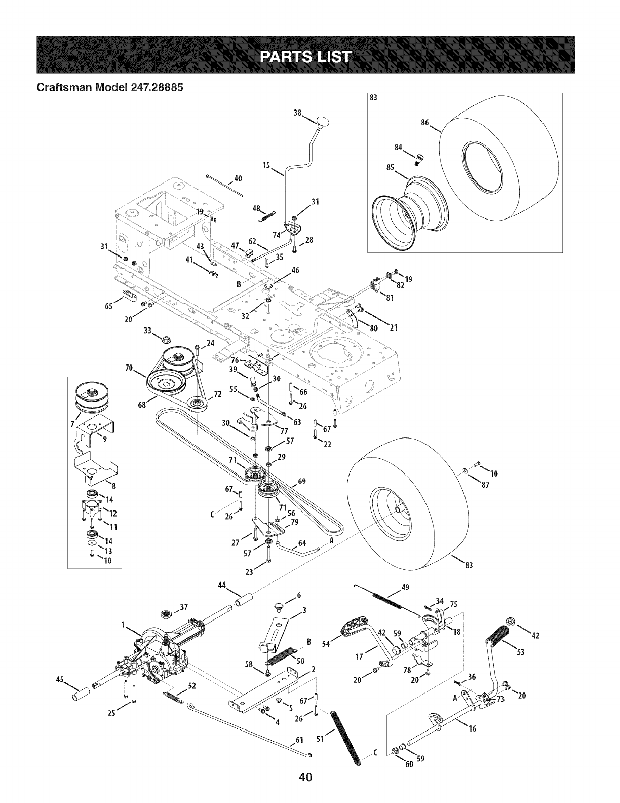
Craftsman Model 247.28885
41
15
35
19
29
B 54
17
4O
20/_

Craftsman Model 247.28885
I
Ref, IPart No.
1 918-04566
2683-04606
3683-04684
4 710-1260A
5 712-04065
6738-0322A
7 956-04015A
8 683-04522
9 683-04612-0637
10 710-0627
11 710-0778
12 718-04261
13 736-0362
14 941-0600
15 647-04035
16 647-04201-0637
17 647-04203A-0637
18 683-04607
19 710-0227
20 710-04484
21 710-0604A
22 710-0809
23 710-0859
24 710-1007
25 710-1266
26 710-1325
27 710-1858A
28 710-3008
29 912-0240
30 712-0241
31 712-04063
32 912-0431
33 712-0700
34 914-Olll
35 914-0209
36 714-04040
37 718-04407
38 720-04028
39 923-3018
40 725-0157
41 725-1644
42 726-0214
43 926-0320
44 731-04602
Description
Dr Assembly, Autodrive Lt-5
Auto-drive Bracket Assembly
Idler Bracket Assembly
Tap Screw, 5/16-18 x 0.750
Flange Lock Nut, 3/8-16
Shoulder Screw, .625 x .217
Pulley Assembly, Var. Spd. 4.75 Od
Belt Keeper Assembly
Variable Bracket Assembly
Hex Screw 5/16-24.750
Tap Screw, 1/4-20 1.500
Bearing Cup
Wash, Flat .330 X 1.25 X .06
Ball Bearing, 17 x 40 x 12.6203
Lvr Assembly, Shft
Ped Assembly, Drive, Autodrive
Ped Assembly, Cont, Autodrive
Bracket Assembly, Pedal, Autodrive
Screw, Ab, #8-18, 0.500
Screw, Tt, 5/16-18, .750
Screw, Tt, 5/16-18, 0.625
Screw, Tt, 1/4-20, 1.250
Hex Hd. Screw, 3/8-16, 2.50
Screw, Ttsems, 3/8-16, 1.500
Hex Hd. Screw, 5/16-18, 3.50
Screw, Tt, 1/4-20, 1.625,
Screw, Tt, 3/8-16 x 1.75
Hex Hd. Screw, 5/16-18, .75
Nut, Jam, 7/16-20
Nut, Hex, 3/8-24
Nut, Flange Lock Nut, 5/16-18
Nut, Flange Lock Nut, 3/8-16
Nut, Fig, 9/16-18
Pin, Cot, 3/32, 1.0
Pin, Cotter Int- .125 Dia
Pin, Cot, Bow-Tie 72
Hub, Pulley, 5/8 Spline
Knob, Shft
Bali,Joint
Cable, Tie, 3/16 X .05 X 7.4
Switch, Spring, Short
Cap, Push 5/8
Plate, Insulator Nut
Sleeve, .758 X .821 X 3.3125
|
Ref, IPart No,
45 731-04604
46 731-06330
47 731-06894
48 732-04488
49 732-04612
50 732-04616B
51 732-04764
52 732-0716D
53 735-0239
54 735-0662
55 936-0169
56 936-0185
57 738-0372B
58 738-04091A
59 741-0495
60 741-3065B
61 747-05188
62 747-05243
63 747-05251A
64 747-05415
65 948-0334
66 750-04456
67 750-0566A
68 954-04208
69 954-0467A
70 956-04002
71 756-04224
72 756-04325
73 783-04536B-0637
74 783-04595A
75 783-06278
76 783-06562-0637
77 783-06592A
78 783-06641
79 783-06769
80 783-06807
81 725-04363
82 17962
83 634-04641-0961
84 634-04369-4042
85 934-0255
86 734-1729
87 736-0242
-- 925-04082
Description
Sleeve, .758 X .821 X 2.4375
Plug, Deck Hole, 7/8
Shift Plate Bearing
Spring, Ext, .38 Od X 3.25 Lg
Spring, Extn, .70 Dia X 12.00 Lg
Spring, Extn, .97 Od X 6.18 Lg
Spring, Extn, .56 X 12.05 x .068
Spring, Extn, .59 Od X 4.00 Lg
Pad, Foot, 4.0 Long
Pad, Cont
Wash, Lock, 3/8, Regular Duty
Wash, Flat, .375 X .738 X .063
Spacer, Shoulder, 1.00 X .38 X .38
Screw, Shoulder, A3x.29, Tt, 5/16-18
Bearing, Fig, .630 Idx .695 Od X .60
Bearing, Hex Fig, .628 Id, Split
Rod, Brake, Lt-5 Trans
Rod, Shift, Lt-5 Stretch 46"
Rod, Adj, Idlr, 3/8
Rod, Trans, Footpedal Bypass
Spacer, T-Axle .68
Spacer, .260 X .372 X 1.420 Lg
Spacer, .260 X .375 X 1.030 Lg
Belt, V Typ, 51 X 40.9 Lg Poly
Belt, V Typ, 51,90.80, Poly
Pulley, Idlr, Flat 7.25 Od
Pulley, Idlr, Flat 2.75 Od
Pulley, Idlr, V-Type X 3.06
Bracket, Ped, Support Lt-5
Bracket, Shft, Adj
Pit, Bracket, Reinforcement
Bracket, Ped, Frame Rh
Bracket, Idlr, Dbl Autodrive
Bracket, Supt, Pedal Stap
Bracket, Idlr, Center Dbl
Pedal Stop Plate
Interlock Switch
Switch Plate
Wheel Assembly, 18 x 9.5 x 8 Sq. Sh.
Rim Assembly
Valve Stem
Tire, 18x9.5 x8 Sq. Sh.
Bell Washer, .340 x .872 x .060
Wiring Harness (NotShown)
41
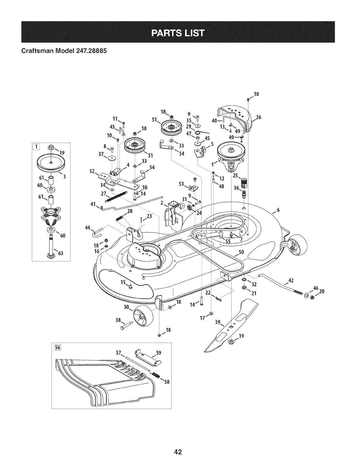
Craftsman Model 247.28885
I0
18
42
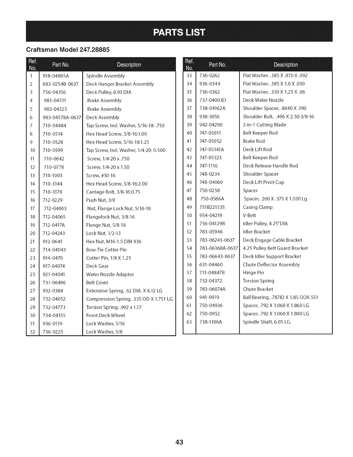
Craftsman Model 247.28885
1
2
3
4
5
6
7
8
9
10
11
12
13
14
15
16
17
18
19
20
21
22
23
24
25
26
27
28
29
3O
31
32
918-04865A
683-0254B-0637
756-04356
983-04511
983-04525
983-04578A-0637
710-04484
710-0514
710-0528
710-0599
710-0642
710-0778
710-1003
710-3144
710-3178
712-0229
712-04063
712-04065
712-0417A
712-04243
912-0641
714-04043
914-0470
917-04074
921-04041
731-06496
932-0384
732-04652
732-04773
734-04155
936- 0119
736-0225
Spindle Assembly
Deck Hanger Bracket Assembly
Deck Pulley, 6.93 DIA
Brake Assembly
Brake Assembly
Deck Assembly
Tap Screw, Ind. Washer, 5/16-18:.750
Hex Head Screw, 3/8-16:1.00
Hex Head Screw, 5/16-18:1.25
Tap Screw, Ind. Washer, 1/4-20:0.500
Screw, 1/4-20 x .750
Screw, 1/4-20 x 1.50
Screw, #10-16
Hex Head Screw, 3/8-16:2.00
Carriage Bolt, 3/8-16:0.75
Push Nut, 3/8
Nut, Flange Lock Nut, 5/16-18
Flangelock Nut, 3/8-16
Flange Nut, 5/8-18
Lock Nut, 1/2-13
Hex Nut, M16-1.5 DIN 936
Bow-Tie Cotter Pin
Cotter Pin, 1/8 X 1.25
Deck Gear
Water Nozzle Adaptor
Belt Cover
Extension Spring, .62 DIA. X 6.12 LG
Compression Spring, .535 OD X 1.751 LG
Torsion Spring, .992 x 1.17
Front Deck Wheel
Lock Washer, 5/16
Lock Washer, 5/8
m
@l
33
34
35
36
37
38
39
4O
41
42
43
44
45
46
47
48
49
5O
51
52
53
54
55
56
57
58
59
6O
61
62
63
736-0262
936-0344
736-0362
737-04003D
738-04162A
938-3056
942-04290
747-05011
747-05052
747-05141A
747-05323
747-1116
748-0234
748-04069
750-0258
750-0566A
751B221535
954-04219
756-04129B
783-05946
783-06243-0637
783-06368A-0637
783-06643-0637
631-04460
711-04847B
732-04372
783-06074A
941-0919
750-04936
750-0952
738-1186A
Flat Washer, .385 X .870 X .092
Flat Washer, .385 X 1.0 X .030
Flat Washer, .330 X 1.25 X .06
Deck Water Nozzle
Shoulder Spacer, .8840 X .190
Shoulder Bolt, .496 X 2.50:3/8-16
2-in-1 Cutting Blade
Belt Keeper Rod
Brake Rod
Deck Lift Rod
Belt Keeper Rod
Deck Release Handle Rod
Shoulder Spacer
Deck Lift Pivot Cup
Spacer
Spacer, .260 X .375 X 1.030 Lg
Casing Clamp
V-Belt
Idler Pulley, 4.25"DIA
Idler Bracket
Deck Engage Cable Bracket
4.25 Pulley Belt Guard Bracket
Deck Idler Support Bracket
Chute Deflector Assembly
Hinge Pin
Torsion Spring
Chute Bracket
Ball Bearing, .7871D X 1.85 ODX.551
Spacer, .792 X 1.060 X 1.860 LG
Spacer, .792 X 1.060 X 1.800 LG
Spindle Shaft, 6.05 LG.
43
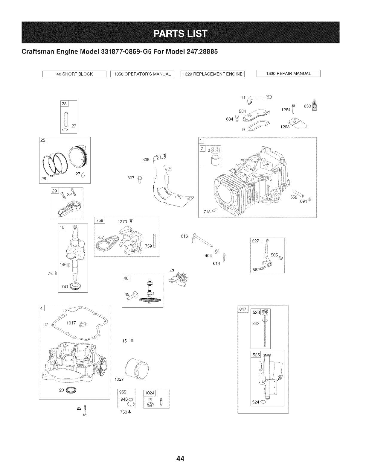
Craftsman Engine Model 331877=0869=G5 For Model 247.28885
48 SHORT BLOCK 1058 OPERATOR'S MANUAL ] I1329 REPLACEMENT ENGINE ] 1330 REPAIR MANUAL
26
12 1017_i_2__'_ _-'-.__i i
200
22
306
307 U
k_
15 _
1027
75O &
43
616
11 ,_
584 ..-/_. __ 1264
9 _ 1263 _-. y
552 _
691 _
718
404 ion.,505
614 _-,'-_¢,_
562 _ _"
847 _
524 d_7,
44
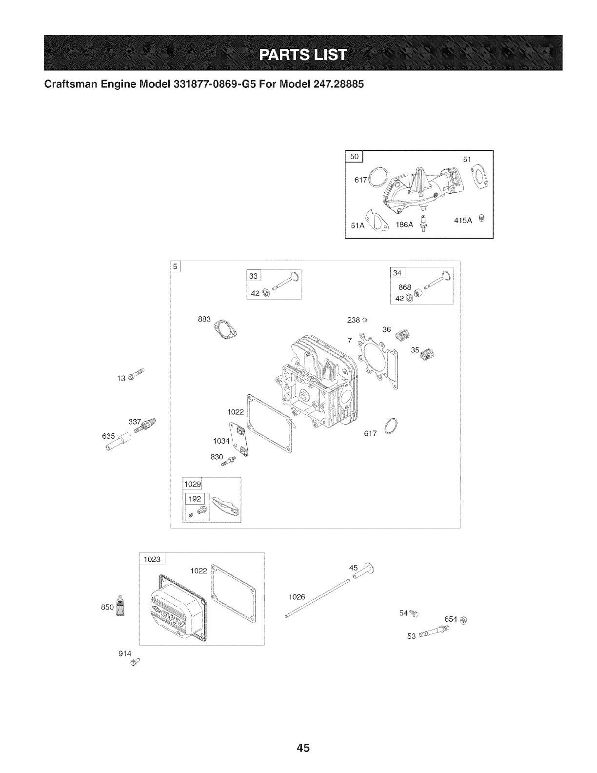
Craftsman Engine Model 331877=0869=G5 For Model 247.28885
5__ 51
51A 186A _ 415A
13_
635_
883
1022
617
i1029}
85O
102
914
1026 _
54% 654 _
53 .......
45
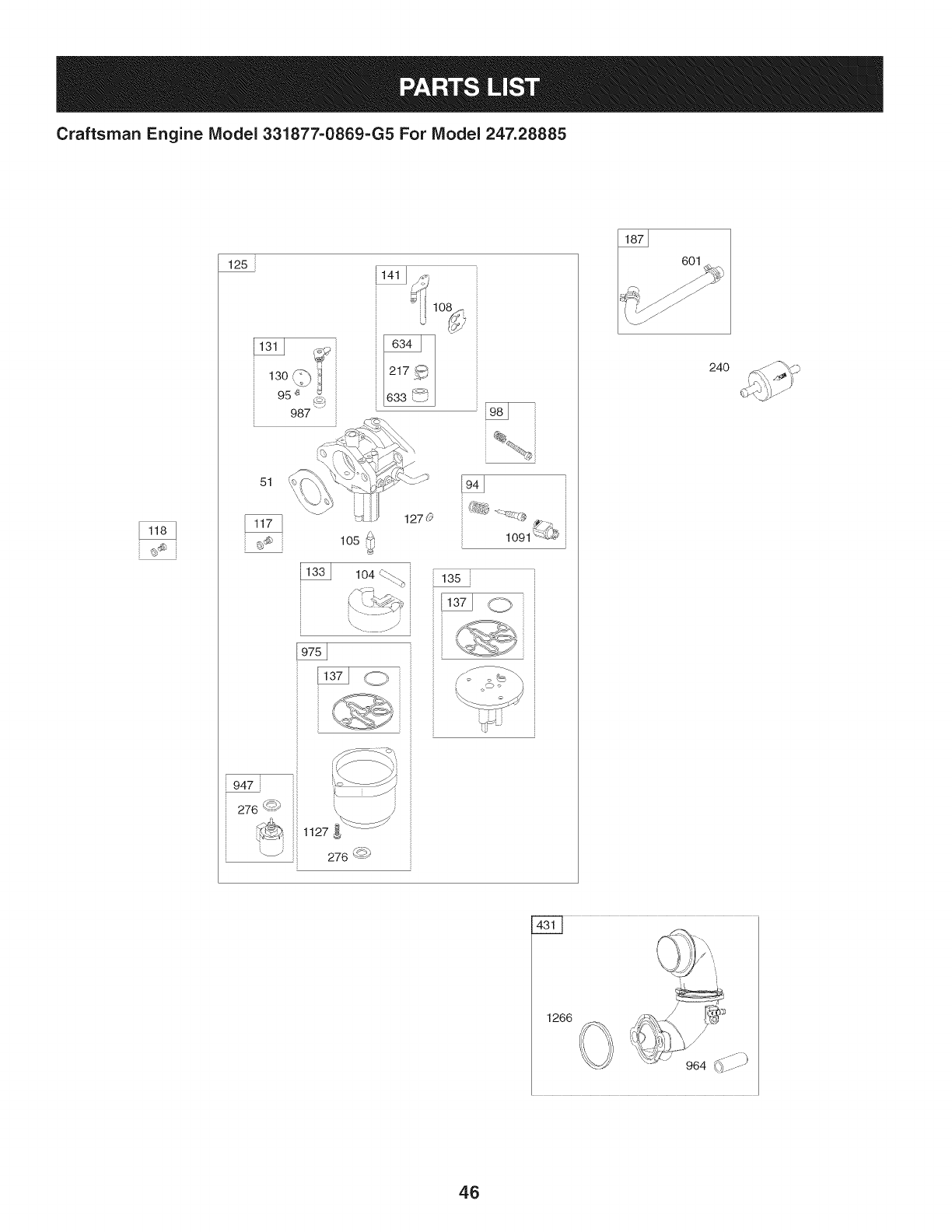
Craftsman Engine Model 331877-0869-G5 For Model 247.28885
125
13o 1
95 '_ _
987
51
lO2
1270
1091 {{L#
947
276 <_')
_ 1127
_ 276 '-<_
601
24O
1266
46
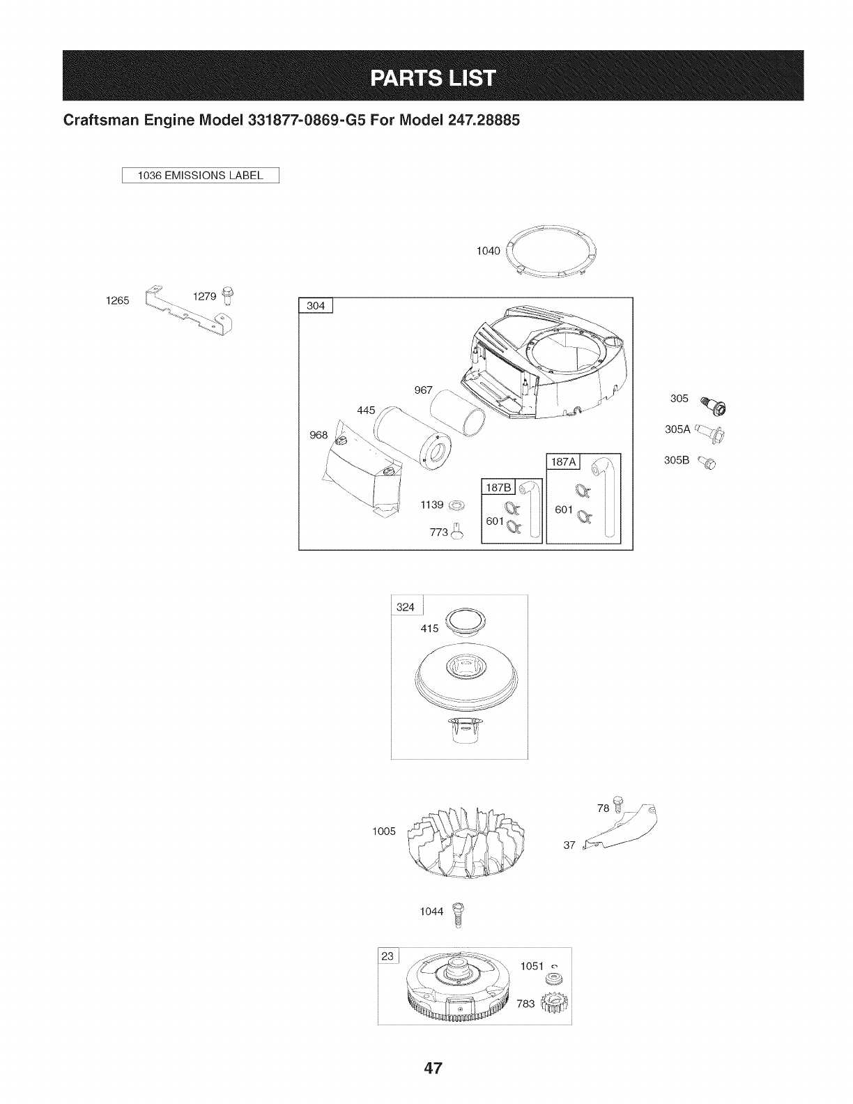
Craftsman Engine IViodel 331877=0869=G5 For IViodel 247.28885
1036 EMiSSiONS LABEL
1265
1139 _._,
305
UZ_--..
305A -.. 7_',
305B _._
,324i _,
415 _//:!!!i!!--_
\ .J
1005
78 _¢
37 '_f_
1044
47
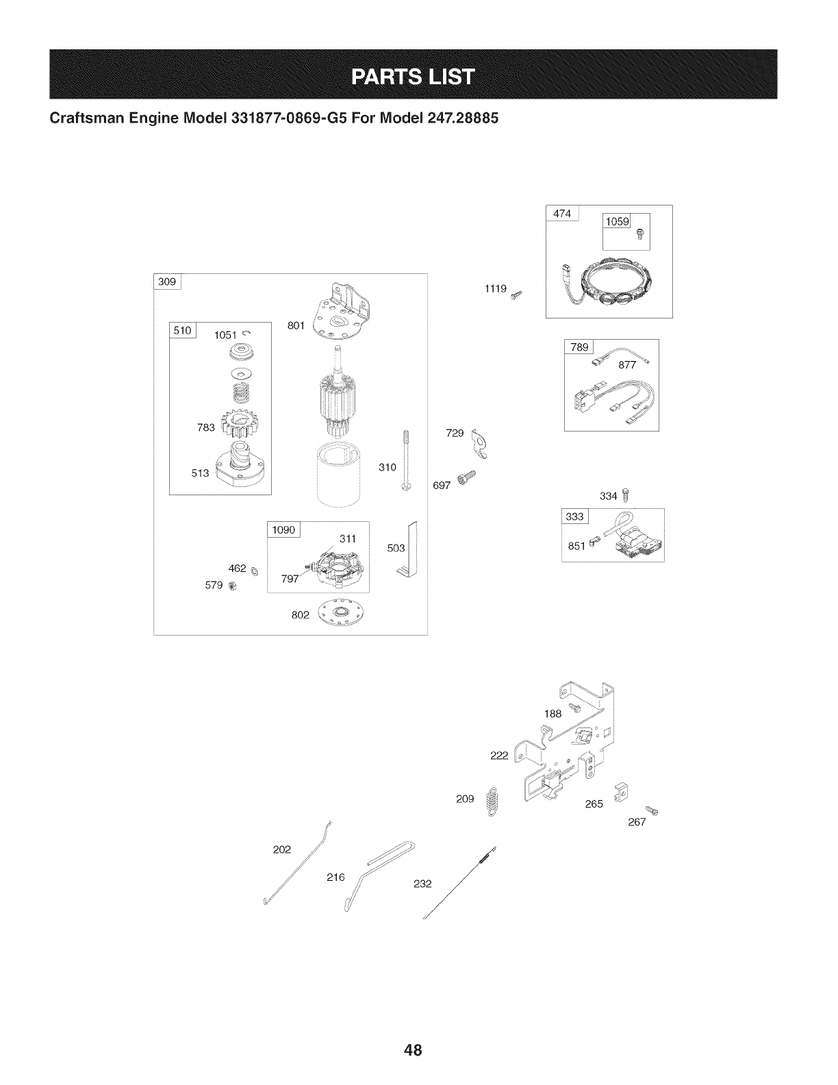
Craftsman Engine IViodel 331877-0869-G5 For IViodel 247.28885
309
1051 <"
783
513
801
310 iii
462 _;
579 _
802
729
697 _
1119
474
334
851
216
2O9
,,,_/ 232
265
267
48
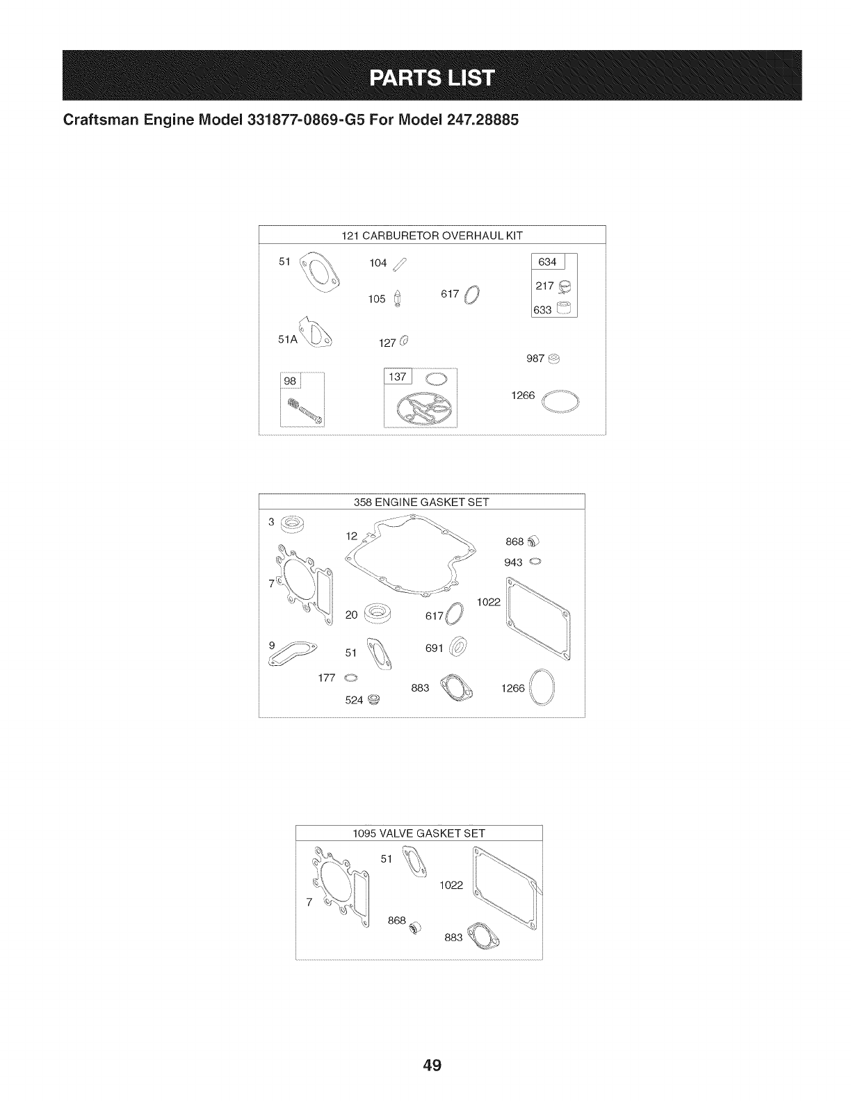
Craftsman Engine Model 331877=0869=G5 For Model 247.28885
51
121 CARBURETOR OVERHAUL KIT
104 _lO50 61__,
127 (_'
987 4_b
, 1266 _ ;_" ;_
ti
/
358 ENGINE GASKET SET
12
1o22
,_
691 _'7//'
1266
1095 VALVE GASKET SET
51
1022
49

Craftsman Engine Model 331877=0869=G5 For Model 247.28885
I
Ref. I Part No.
NO, I
1 794128
2 399265
3 391086s
4 697188
5 796026
7 794114
9 697109
11 794683
12 697110
13 793988
15 690946
16 797579
20 795387
22 692125
23 698281
24 796335
25 795858
795877
26 794126
794127
27 698469
28 795861
29 794122
32 791118
33 792868
34 791935
35 691279
36 691279
37 699882
42 499586
43 691968
45 690564
46 793880
48 795446
50 796180
51 692137
51A 794312
53 690227
54 691148
78 691693
94 793610
95 690718
Description
Cylinder Assembly
Bushing/Seal Kit (Magneto Side)
Seal-Oil (Magneto Side)
Sump-Engine
Head-Cylinder
Gasket-Cylinder Head
Gasket-Breather
Tube-Breather
Gasket-Crankcase
Screw (Cylinder Head)
Plug-Oil Drain
Crankshaft
Seal-Oil (PTO Side)
Screw (Crankcase Cover/Sump)
Flywheel
Key-Flywheel (Steel)
Piston Assembly (Standard)
Piston Assembly (020" Oversize)
Ring Set (Standard)
Ring Set (.020" Oversize)
Lock-Piston Pin
Pin-Piston
Rod-Connecting
Screw (Connecting Rod)
Valve-Exhaust
Valve-Intake
Spring-Valve (Intake)
Spring-Valve (Exhaust)
Guard-Flywheel
Keeper-Valve
Slinger-Governor/Oil
Tappet-Va Ive
Camshaft
Short Block
Manifold-Intake
Gasket-Intake
Gasket-Intake
Stud (Carburetor)
Screw (Intake Manifold)
Screw (Flywheel Guard)
Kit-Idle Mixture
Screw (Throttle Valve)
Ref,
No,
98 695408
104 694918
105 696136
108 695419
117 796251
118 791406
121 796184
125 796587
127 690727
130 792747
131 792765
133 694914
135 698780
137 698781
141 792777
146 691639
186 794873
187 791805
187A 791806
187B 791744
188 691693
192 691986
202 691841
209 692208
216 691840
217 695409
222 694042
227 691374
232 691842
238 691843
240 394358s
265 691024
267 794904
276 695410
304 798670
305 697102
305A 793376
305B 795891
306 794953
307 691693
309 693551
IPart No, Description
Kit-Idle Speed
Pin-Float Hinge
Valve-Float Needle
Valve-Choke
Jet-Main (Standard)
Jet-Main (High Altitude)
Kit-Carburetor Overhaul
Carburetor
Plug-Welch
Va Ive-Th rottle
Kit-Throttle Shaft
Float-Carburetor
Tube-Fuel Transfer
Gasket-Float Bowl
Kit-Choke Shaft
Key-Timing
Hose-Connector (Intake Manifold)
Line-Fuel (Formed) (Cut to Length)
Line-Fuel (Formed) (21") (Cut to Length)
Line-Fuel (Formed) (14") (Cut to Length)
Screw (Control Bracket)
Adjuster-Rocker Arm
Link-Mechanical Governor
Spring-Governor (Green)
Link-Choke
Spring-Choke Return
Bracket-Control
Lever-Governor Control
Spring-Governor Link
Cap-Valve
Filter-Fuel
Clamp-Casing
Screw (Casing Clamp)
Washer-Sealing
Housing-Blower
Screw (Blower Housing) (1/4-20x1.14)
Screw (Blower Housing) (1/4-20x.68)
Screw (Blower Housing) (Blower Housing to
Elbow)
Shield-Cylinder
Screw (Cylinder Shield)
Motor-Starter
5O
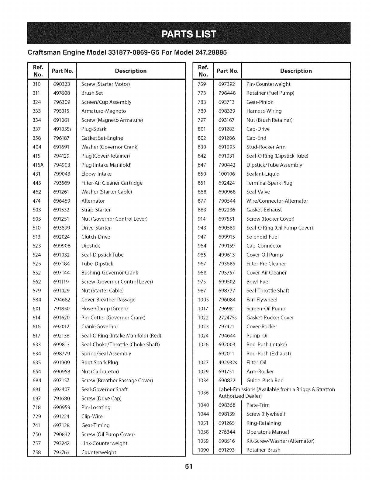
Craftsman Engine Model 331877-0869-G5 For Model 247.28885
Ref,
No,
310 690323
311 497608
324 796309
333 795315
334 691061
337 491055s
358 796187
404 691691
415 794129
415A 794903
431 799043
445 793569
462 691261
474 696459
503 691532
505 691251
510 693699
513 692024
523 699908
524 691032
525 697184
552 697144
562 691119
579 691029
584 794682
601 791850
614 691620
616 692012
617 692138
633 699813
634 698779
635 691909
654 690958
684 697157
691 692407
697 791680
718 690959
729 691224
741 697128
750 790832
757 793242
758 793763
IPart No. Description
Screw (Starter Motor)
Brush Set
Screen/Cup Assembly
Armature-Magneto
Screw (Magneto Armature)
Plug-Spark
Gasket Set-Engine
Washer (Governor Crank)
Plug (Cover/Retainer)
Plug (Intake Manifold)
Elbow-Intake
Filter-Air Cleaner Cartridge
Washer (Starter Cable)
Alternator
Strap-Starter
Nut (Governor Control Lever)
Drive-Sta rter
Clutch-Drive
Dipstick
Seal-Dipstick Tube
Tube-Dipstick
Bushing-Governor Crank
Screw (Governor Control Lever)
Nut (Starter Cable)
Cover-Breather Passage
Hose-Clamp (Green)
Pin-Cotter (Governor Crank)
Crank-Governor
Seal-O Ring (Intake Manifold) (Red)
Seal-Choke/Throttle (Choke Shaft)
Spring/Seal Assembly
Boot-Spark Plug
Nut (Carburetor)
Screw (Breather Passage Cover)
Seal-Governor Shaft
Screw (Drive Cap)
Pin-Locating
Clip-Wire
Gear-Timing
Screw (Oil Pump Cover)
Link-Counterweight
Counterweight
I
Ref, IPart No,
No, I
759 697392
773 796448
783 693713
789 698329
797 693167
801 691283
802 691286
830 691095
842 691031
847 790442
850 100106
851 692424
868 690968
877 790544
883 692236
914 697551
943 690589
947 699915
964 799159
965 499613
967 793685
968 795757
975 699502
987 698777
1005 796084
1017 796981
1022 272475s
1023 797421
1024 794644
1026 692003
692011
1027 492932s
1029 691751
1034 690822
1036
1040
1044
1051
1058
1059
1090
Description
Pin-Counterweight
Retainer (Fuel Pump)
Gear-Pinion
Harness-Wiring
Nut (Brush Retainer)
Cap-Drive
Cap-End
Stud-Rocker Arm
Seal-O Ring (Dipstick Tube)
Dipstick/Tube Assembly
Sealant-Liquid
Terminal-Spark Plug
Seal-Valve
Wire/Connector-Alternator
Gasket-Exhaust
Screw (Rocker Cover)
Seal-O Ring (Oil Pump Cover)
Solenoid-Fuel
Cap-Connector
Cover-Oil Pump
Filter-Pre Cleaner
Cover-Air Cleaner
Bowl-Fuel
Seal-Throttle Shaft
Fan-Flywheel
Screen-Oil Pump
Gasket-Rocker Cover
Cover-Rocker
Pump-Oil
Rod-Push (Intake)
Rod-Push (Exhaust)
Filter-Oil
Arm-Rocker
Guide-Push Rod
Label-Emissions (Available from a Briggs & Stratton
Authorized Dealer)
698368
698139
691265
276344
698516
691293
Plate-Trim
Screw (Flywheel)
Ring-Retaining
Operator's Manual
Kit-Screw/Washer (Alternator)
Retainer-Brush
51
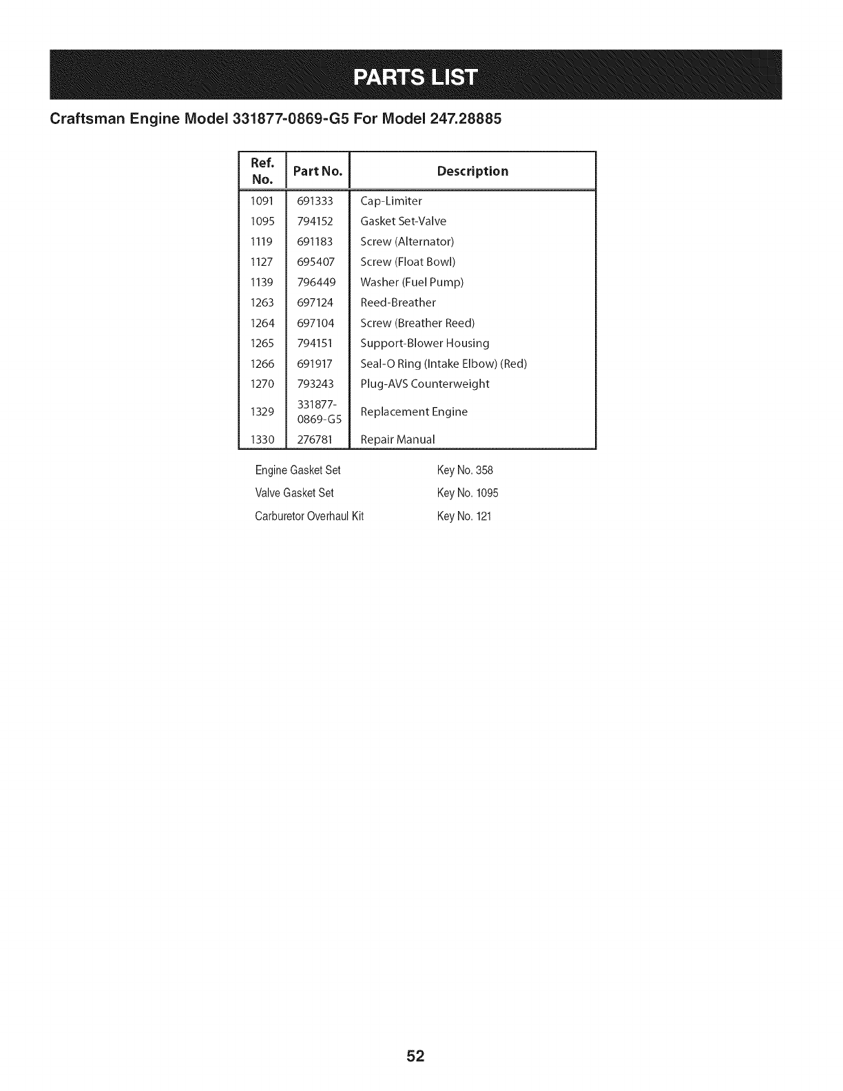
Craftsman Engine Model 331877=0869=G5 For Model 247.28885
Ref,
No,
1091 691333
1095 794152
1119 691183
1127 695407
1139 796449
1263 697124
1264 697104
1265 794151
1266 691917
1270 793243
331877-
1329 0869-G5
1330 276781
IPart No. Description
Cap-Limiter
Gasket Set-Valve
Screw (Alternator)
Screw (Float Bowl)
Washer (Fuel Pump)
Reed-Breather
Screw (Breather Reed)
Support-Blower Housing
Seal-O Ring (Intake Elbow) (Red)
Plug-AVS Counterweight
Replacement Engine
Repair Manual
EngineGasketSet
ValveGasketSet
CarburetorOverhaulKit
KeyNo.358
KeyNo.1095
KeyNo.121
52
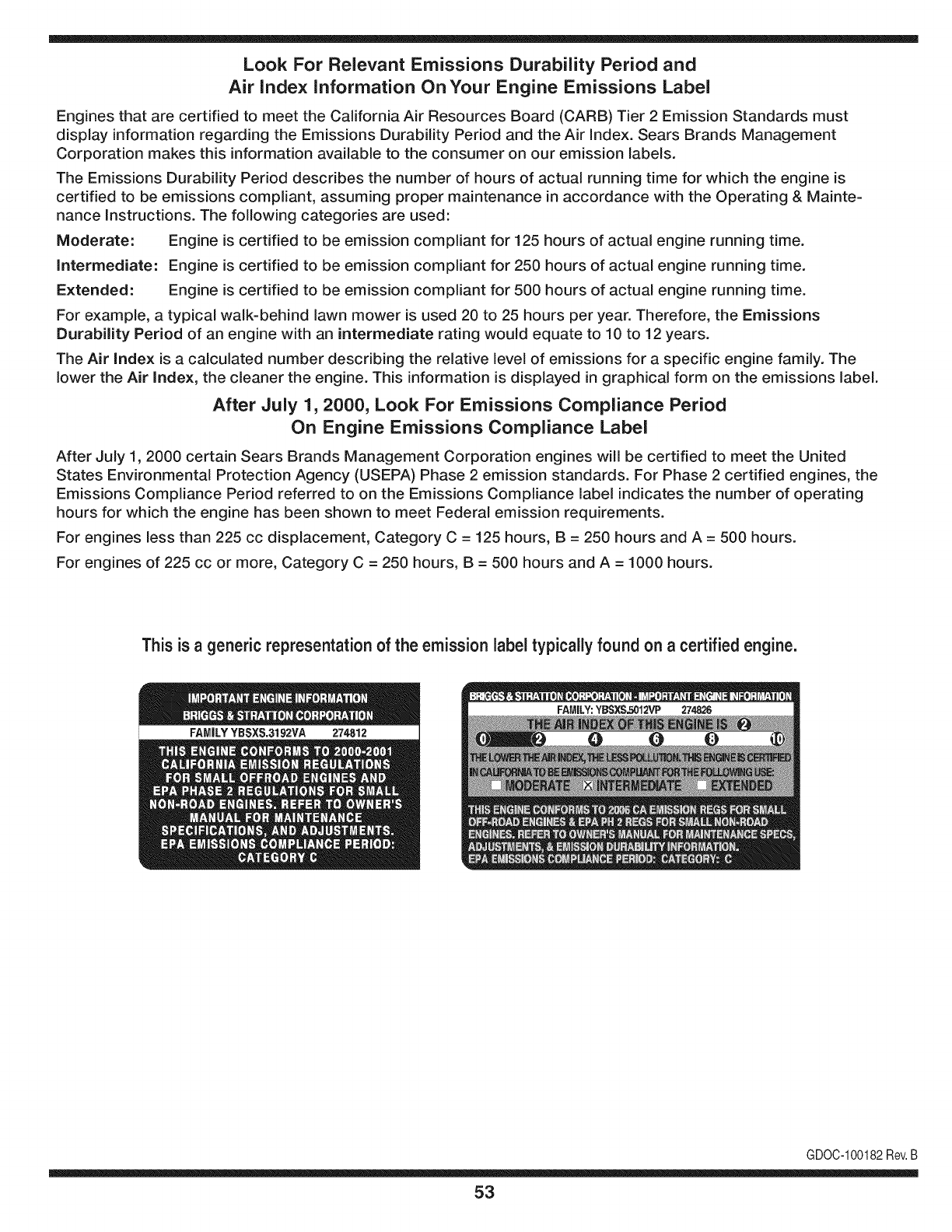
Look For Relevant Emissions Durability Period and
Air index information On Your Engine Emissions Label
Engines that are certified to meet the California Air Resources Board (CARB) Tier 2 Emission Standards must
display information regarding the Emissions Durability Period and the Air Index. Sears Brands Management
Corporation makes this information available to the consumer on our emission labels.
The Emissions Durability Period describes the number of hours of actual running time for which the engine is
certified to be emissions compliant, assuming proper maintenance in accordance with the Operating & Mainte-
nance Instructions. The following categories are used:
Moderate: Engine is certified to be emission compliant for 125 hours of actual engine running time.
Intermediate: Engine is certified to be emission compliant for 250 hours of actual engine running time.
Extended: Engine is certified to be emission compliant for 500 hours of actual engine running time.
For example, a typical walk-behind lawn mower is used 20 to 25 hours per year. Therefore, the Emissions
Durability Period of an engine with an intermediate rating would equate to 10 to 12 years.
The Air index is a calculated number describing the relative level of emissions for a specific engine family. The
lower the Air Index, the cleaner the engine. This information is displayed in graphical form on the emissions label.
After July 1,2000, Look For Emissions Compliance Period
On Engine Emissions Compliance Label
After July 1, 2000 certain Sears Brands Management Corporation engines will be certified to meet the United
States Environmental Protection Agency (USEPA) Phase 2 emission standards. For Phase 2 certified engines, the
Emissions Compliance Period referred to on the Emissions Compliance label indicates the number of operating
hours for which the engine has been shown to meet Federal emission requirements.
For engines less than 225 cc displacement, Category C = 125 hours, B = 250 hours and A = 500 hours.
For engines of 225 cc or more, Category C = 250 hours, B = 500 hours and A = 1000 hours.
This is ageneric representation of the emission label typically found on a certified engine.
FAMILYYBSXS.3192VA 274812
GDOC-100182Rev.B
53
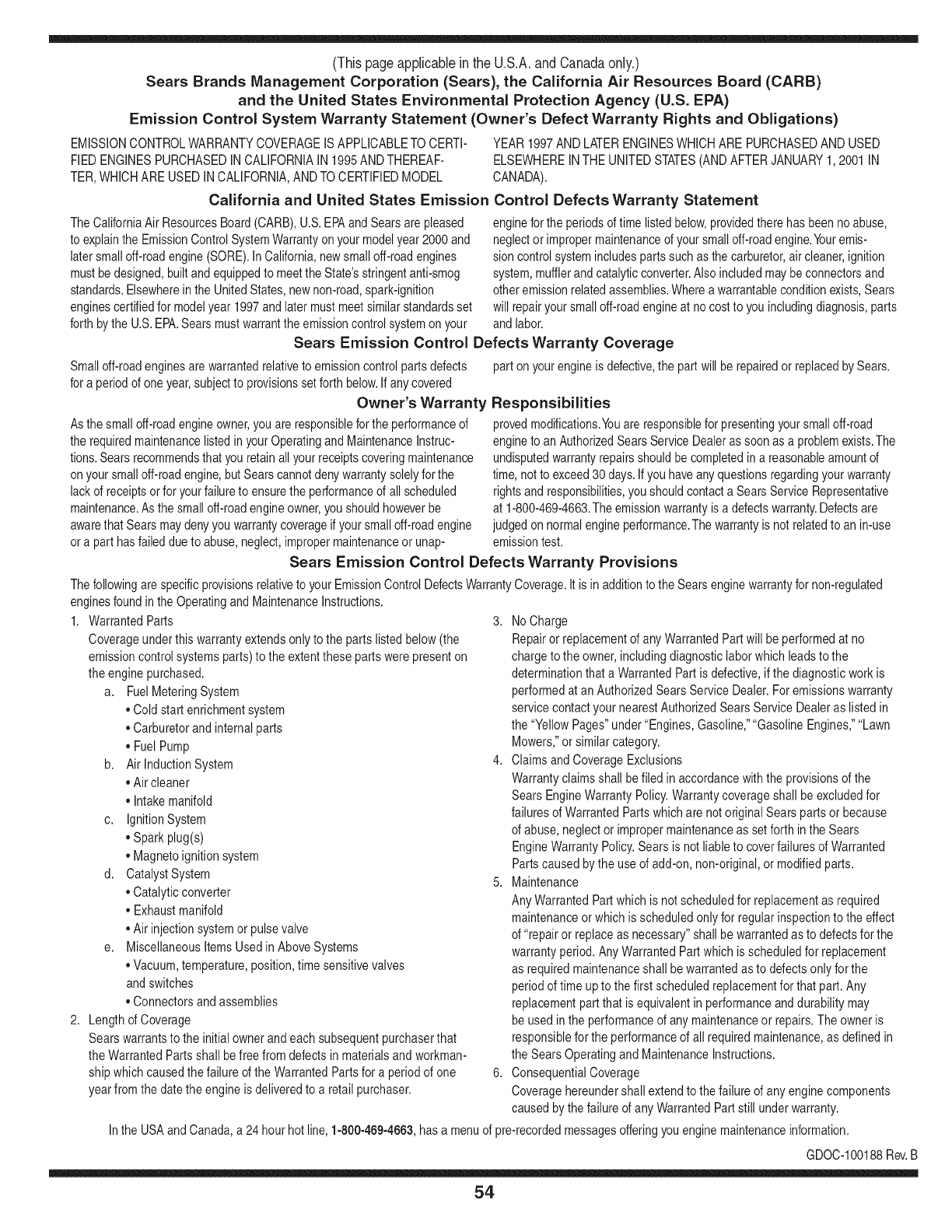
(Thispageapplicableinthe U.S.A.and Canadaonly.)
Sears Brands Management Corporation (Sears), the California Air Resources Board (CARD)
and the United States Environmental Protection Agency (U.S. EPA)
Emission Control System Warranty Statement (Owner's Defect Warranty Rights and Obligations)
EMISSIONCONTROLWARRANTYCOVERAGEISAPPLICABLETOCERTI-
FIEDENGINESPURCHASEDINCALIFORNIAIN1995ANDTHEREAF-
TER,WHICHARE USEDINCALIFORNIA,ANDTOCERTIFIEDMODEL
California and United States Emission
The CaliforniaAir ResourcesBoard(CARD),U.S.EPAand Searsare pleased
to explainthe EmissionControlSystemWarrantyon your modelyear2000and
latersmalloff-roadengine(SORE).InCalifornia,newsmall off-roadengines
mustbe designed,builtand equippedto meettheState'sstringentanti-smog
standards.Elsewherein theUnitedStates,newnon-road,spark-ignition
enginescertifiedfor modelyear 1997and latermustmeetsimilarstandardsset
forthbythe U.S.EPA.Searsmustwarranttheemissioncontrolsystemon your
YEAR1997ANDLATERENGINESWHICHARE PURCHASEDANDUSED
ELSEWHEREINTHEUNITEDSTATES(ANDAFTERJANUARY1,2001 IN
CANADA).
Control Defects Warranty Statement
enginefor theperiodsoftime listedbelow,providedtherehasbeen noabuse,
neglector impropermaintenanceof your smalloff-roadengine.Youremis-
sion controlsystemincludespartssuch as thecarburetor,air cleaner,ignition
system,mufflerand catalyticconverter.Also includedmaybe connectorsand
otheremissionrelatedassemblies.Wherea warrantableconditionexists,Sears
will repairyour smalloff-roadengineat no costto you includingdiagnosis,parts
and labor.
Sears Emission Control Defects Warranty Coverage
Smalloff-roadenginesarewarrantedrelativeto emissioncontrolpartsdefects
fora periodof one year,subjectto provisionsset forthbelow.Ifanycovered
Owner's Warranty
Asthe smalloff-roadengineowner,you are responsiblefor theperformanceof
therequiredmaintenancelistedin yourOperatingand MaintenanceInstruc-
tions.Searsrecommendsthatyou retainallyourreceiptscoveringmaintenance
onyoursmalloff-roadengine,butSearscannotdenywarrantysolelyfor the
lackof receiptsorfor yourfailureto ensuretheperformanceof all scheduled
maintenance.As the smalloff-roadengineowner,youshouldhoweverbe
awarethat Searsmaydenyyou warrantycoverageifyour smalloff-roadengine
ora part hasfaileddueto abuse,neglect,impropermaintenanceor unap-
parton yourengineis defective,the part willbe repairedorreplacedbySears.
Responsibilities
provedmodifications.Youare responsiblefor presentingyour smalloff-road
engineto an AuthorizedSearsServiceDealeras soonas a problemexists.The
undisputedwarrantyrepairsshouldbecompletedina reasonableamountof
time,notto exceed30days.Ifyouhaveanyquestionsregardingyourwarranty
rightsand responsibilities,you shouldcontacta SearsService Representative
at 1-800-469-4663.Theemissionwarrantyis a defectswarranty.Defectsare
judgedon normalengineperformance.Thewarrantyis notrelatedto an in-use
emissiontest.
Sears Emission Control Defects Warranty Provisions
ThefollowingarespecificprovisionsrelativetoyourEmissionControlDefectsWarrantyCoverage.ItisinadditiontotheSearsenginewarrantyfornon-regulated
enginesfoundin theOperatingand MaintenanceInstructions.
1. WarrantedParts
Coverageunderthis warrantyextendsonly to the parts listedbelow(the
emissioncontrolsystemsparts)to the extentthese partswere presenton
the enginepurchased.
a. FuelMeteringSystem
•Cold start enrichmentsystem
•Carburetorand internalparts
•FuelPump
b. AirlnductionSystem
•Aircleaner
•Intakemanifold
c. IgnitionSystem
•Sparkplug(s)
•Magnetoignitionsystem
d. CatalystSystem
•Catalyticconverter
•Exhaustmanifold
•Air injectionsystemor pulsevalve
e. MiscellaneousItemsUsedin AboveSystems
•Vacuum,temperature,position,timesensitivevalves
andswitches
•Connectorsandassemblies
2. Lengthof Coverage
Searswarrantsto the initialownerand eachsubsequentpurchaserthat
the WarrantedParts shallbefree fromdefects in materialsandworkman-
shipwhich causedthefailure of the WarrantedPartsfor a periodof one
yearfromthe datethe engineis deliveredto a retailpurchaser.
3. NoCharge
Repairor replacementof anyWarrantedPartwill be performedat no
chargeto the owner,includingdiagnosticlabor whichleadsto the
determinationthata WarrantedPartisdefective,ifthe diagnosticwork is
performedat an AuthorizedSears ServiceDealer.Foremissionswarranty
servicecontact yournearestAuthorizedSears ServiceDealeras listed in
the "YellowPages"under"Engines,Gasoline,""GasolineEngines,""Lawn
Mowers,"orsimilarcategory.
4. Claimsand CoverageExclusions
Warrantyclaimsshall be filed in accordancewiththe provisionsof the
SearsEngineWarrantyPolicy.Warrantycoverageshall beexcludedfor
failuresof WarrantedPartswhichare notoriginal Searspartsor because
of abuse,neglector impropermaintenanceas setforth inthe Sears
EngineWarrantyPolicy.Searsis notliableto coverfailuresof Warranted
Partscausedby theuse of add-on,non-original,or modifiedparts.
5. Maintenance
Any WarrantedPart whichis notscheduledfor replacementas required
maintenanceor whichis scheduledonly for regularinspectionto the effect
of "repairor replaceas necessary"shallbe warrantedasto defectsfor the
warrantyperiod.AnyWarrantedPartwhich is scheduledfor replacement
as requiredmaintenanceshallbe warrantedasto defectsonly forthe
periodof time up to the first scheduledreplacementfor that part. Any
replacementpartthat is equivalentin performanceand durabilitymay
be usedin the performanceof any maintenanceor repairs.The owneris
responsibleforthe performanceof allrequiredmaintenance,as definedin
the SearsOperatingand MaintenanceInstructions.
6. ConsequentialCoverage
Coveragehereundershallextend to thefailure of anyengine components
caused bythe failureof anyWarrantedPartstill underwarranty.
Inthe USAandCanada,a 24 hourhot line, 1-800-469-4663,has a menuof pre-recordedmessagesofferingyou enginemaintenanceinformation.
GD0C-100188Rev.B
54
FEDERAL and/or CALIFORNIA EMISSION CONTROL WARRANTY STATEMENT
YOUR WARRANTY RIGHTS AND OBLIGATIONS
MTDConsumerGroupInc,the UnitedStatesEnvironmentalProtectionAgency (EPA),and, forthose productscertifiedfor sale in the stateof California,the
CaliforniaAir ResourcesBoard(CARB)are pleasedto explainthe emission(evaporativeand/or exhaust)controlsystem(ECS) warrantyonyouroutdoor2006
andlater smalloff-roadspark-ignitedengine andequipment(outdoorequipmentengine)In California,new outdoorequipmentengines mustbe designed,built and
equippedto meetthe State'sstringentanti-smogstandards(inotherstates, 1997andlater modelyear equipmentmustbe designed,built, and equippedto meet
theU.S. EPAsmalloff-road,sparkignitionengineregulations.MTDConsumerGroupInc mustwarrantthe ECSon your outdoorequipmentenginefor the periodof
timelisted belowprovidedtherehas been noabuse, neglector impropermaintenanceof outdoor equipmentengine.
YourECSmayincludeparts suchas thecarburetor,fuel-injectionsystem,the ignitionsystem,catalyticconverter,fuel tanks,fuel lines,fuelcaps,valves,canisters,
filters,vaporhoses,clamps,connectors,andotherassociatedemission-relatedcomponents.
Wherea warrantableconditionexists, MTDConsumerGroupIncwill repairyouroutdoorequipmentengineat no cost to youincludingdiagnosis,parts and labor.
MAN UFACTURER'S WARRANTY COVERAGE:
Thisemissioncontrolsystemiswarrantedfor two years. If anyemission-relatedpart onyour outdoorequipmentengineis defective,the part will berepairedor
replacedby MTDCONSUMERGROUPINC.
OWNER'S WARRANTY RESPONSIBILITIES:
Asthe outdoorequipmentengineowner,you are responsiblefor performanceof the requiredmaintenancelisted inyour owner'smanual.MTDConsumerGroup
Inc recommendsthat you retainallreceiptscoveringmaintenanceon youroutdoorequipmentengine,butMTDConsumerGroupInc cannotdeny warrantysolely
forthe lackof receipts.
Asthe outdoorequipmentengineowner,you shouldhoweverbe awarethat MTDConsumerGroupInc maydenyyou warrantycoverageifyour outdoorequipment
engineor a part hasfaileddue toabuse,neglect,or impropermaintenanceor unapprovedmodifications.
Youare responsiblefor presentingyouroutdoorequipmentengineto MTDConsumerGroupInc'sdistributioncenterorservicecenteras soon asthe problem
exists.Thewarrantyrepairsshouldbecompletedin a reasonableamountof time, notto exceed30 days.If youhavea questionregardingyour warrantycoverage,
you shouldcontactthe MTDConsumerGroupIncService Departmentat 1-800-800-7310orvia emailat http://support.mtdproducts.com
GENERAL EMISSIONS WARRANTY COVERAGE:
MTDConsumerGroupIncwarrantstothe ultimatepurchaserand eachsubsequentpurchaserthat theoutdoorequipmentengineis: Designed,built and equipped
so asto conformwithall applicableregulations;and freefromdefects in materialsand workmanshipthatcausethe failureof a warrantedpart to be identicalin all
materialrespectsto that part as describedin MTDConsumerGroup Inc'sapplicationfor certification.
The warrantyperiodbeginson thedate theoutdoorequipmentengineis deliveredto anultimatepurchaserorfirst placedintoservice.The warrantyperiodis two
years.
Subjectto certainconditionsand exclusionsasstated below,the warrantyonemission-relatedparts is asfollows:
1. Anywarrantedpart that is notscheduledfor replacementas requiredmaintenancein thewritten instructionssupplied,is warrantedforthe warrantyperiod
statedabove. Ifthe part fails duringthe periodof warrantycoverage,thepart will be repairedor replacedbyMTDConsumerGroupInc accordingto subsection
(4)below.Anysuchpart repairedor replacedunderwarrantywillbewarrantedfor the remainderof the period.
2. Anywarrantedpart that isscheduledonly for regularinspectionin the writteninstructionssupplied is warrantedforthe warrantyperiodstatedabove.Anysuch
partrepairedor replacedunderwarrantywill bewarrantedforthe remainingwarrantyperiod.
3. Anywarrantedpart that isscheduledfor replacementas requiredmaintenancein thewritten instructionssuppliediswarrantedfor the periodof timebeforethe
firstscheduledreplacementdatefor that part.If the partfails beforethefirst scheduledreplacement,the part will berepairedor replacedby MTDConsumer
GroupInc accordingto subsection(4) below.Any suchpart repairedor replacedunderwarrantywill be warrantedfor the remainderof the periodprior to the
firstscheduledreplacementpointfor the part.
4. Repairor replacementof any warrantedpart underthe warrantyprovisionshereinmustbe performedat a warrantystationat no chargeto the owner.
5. Notwithstandingthe provisionsherein,warrantyservicesor repairswill be providedat all of our distributioncentersthatare franchisedto servicethe subject
enginesor equipment.
6. Theoutdoorequipmentengineownerwill notbe chargedfor diagnosticlaborthat isdirectlyassociatedwithdiagnosisof a defective,emission-relatedwar-
rantedpart, providedthat suchdiagnosticwork is performedat a warrantystation.
7. MTDConsumerGroupInc is liablefor damagesto otherengine or equipmentcomponentsproximatelycausedby a failure underwarrantyof anywarranted
part.
8. Throughoutthe off-roadengineand equipmentwarrantyperiodstatedabove,MTDConsumerGroupInc will maintaina supplyof warrantedparts sufficientto
meetthe expecteddemandfor suchparts.
9. Anyreplacementpart maybe usedinthe performanceof any warrantymaintenanceor repairsand mustbe providedwithoutchargeto the owner.Suchusewill
notreducethe warrantyobligationsof MTDConsumerGroupInc.
10.Add-onor modifiedpartsthat are notexemptedbythe Air ResourcesBoardmaynot beused.The useof any non-exemptedadd-onor modifiedpartsby the
ultimatepurchaserwill be groundsfor disallowinga warrantyclaims. MTDConsumerGroup Incwill notbe liableto warrantfailuresof warrantedparts caused
bythe use of a non-exemptedadd-onor modifiedpart.
WARRANTED PARTS:
The repairor replacementof any warrantedpart otherwiseeligiblefor warrantycoveragemaybe excludedfromsuch warrantycoverageif MTDConsumerGroup
Inc demonstratesthatthe outdoor equipmentengine hasbeenabused,neglected,orimproperlymaintained,and thatsuch abuse,neglect,or impropermainte-
nancewasthe direct causeof the needfor repairor replacementof the part.Thatnotwithstanding,any adjustmentof a componentthat hasa factoryinstalled,
andproperlyoperating,adjustmentlimitingdeviceis still eligible for warrantycoverage.Further,the coverageunderthis warrantyextendsonly to partsthat were
presentonthe off-roadengineand equipmentpurchased.
Thefollowing emissionwarrantypartsare covered(if applicable):
(1)FuelMeteringSystem
• Cold start enrichmentsystem(softchoke)
• Carburetorand internalparts(or fuel injectionsystem)
• Fuelpump
• Fueltank
(2)Air InductionSystem
• Aircleaner
• Intakemanifold
(3) IgnitionSystem
• Sparkplug(s)
• Magnetoignitionsystem
(4) ExhaustSystem
• Catalyticconverter
• SAI(Reed valve)
(5) MiscellaneousItemsUsedin AboveSystem
• Vacuum,temperature,position,timesensitivevalvesand switches
• Connectorsandassemblies
(6) EvaporativeControl
• Fuelhose
• Fuelhoseclamps
• Tetheredfuel cap
• Carboncanister
• Vapor lines
GDOC-100223Rev.A
Congratulationson makinga smartpurchase.YournewCraftsman@
productis designedandmanufacturedfor yearsof dependableopera-
tion.But likeall products,it mayrequirerepairfromtimeto time.That's
whenhavinga RepairProtectionAgreementcansaveyoumoneyand
aggravation.
Here'swhatthe RepairProtectionAgreement*includes:
* Expert service byour 10,000professionalrepairspecialists
oUnlimitedserviceand no chargefor partsand laboron all
coveredrepairs
o Product replacementupto $1500if yourcoveredproductcan't be
fixed
•Discountof 10%from regularprice of serviceand relatedinstalled
partsnotcoveredby theagreement;also,10%off regularpriceof
preventivemaintenancecheck
• Fast help by phone- we call it RapidResolution- phonesupport
froma Searsrepresentative.Thinkof usas a "talkingowner's
manual."
Onceyou purchasethe Agreement,a simplephonecall is all thatit
takesfor youto scheduleservice.Youcan call anytimedayor night,or
schedulea serviceappointmentonline.
The RepairProtectionAgreementis a risk-freepurchase.If youcancel
for any reasonduringthe productwarrantyperiod,wewill provideafull
refund.Or,a proratedrefundanytimeafterthe productwarrantyperiod
expires.Purchaseyour RepairProtectionAgreementtoday!
Somelimitationsand exclusionsapply. For pricesand additional
informationin the U.S.A.call 1-800-827-6655.
*Coverage inCanadavaries on some items.Forfull details call
Sears Canadaat 1-800-361-6665.
Sears Installation Service
ForSearsprofessionalinstallationof homeappliances,garagedoor
openers,waterheaters,andothermajorhomeitems,in the U.S.A.or
Canadacall 1-800-4-MY-HOME®.
57
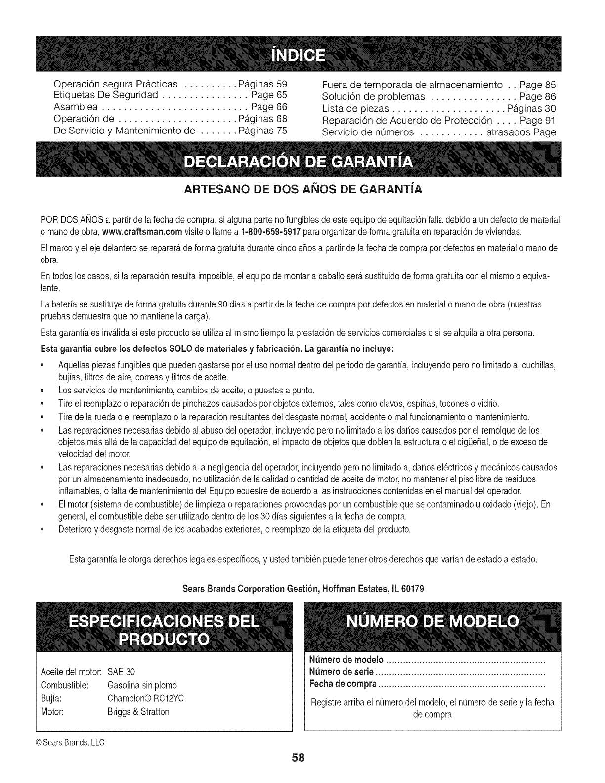
Operaci6n segura Practicas .......... Paginas 59 Fuera de temporada de almacenamiento .. Page 85
Etiquetas De Seguridad ................ Page 65 Solucion de problemas ................ Page 86
Asamblea ........................... Page 66 Lista de piezas ..................... Paginas 30
Operacion de ...................... Paginas 68 Reparaci6n de Acuerdo de Proteccion .... Page 91
De Servicio y Mantenimiento de ....... Paginas 75 Servicio de nOmeros ............ atrasados Page
ARTESANO DE DOS AI_IOS DE GARANT{A
PORDOSANOSa partirde la fechade compra,si algunapartenofungiblesde esteequipodeequitaci6nfalla debidoa undefectodematerial
o manode obra,www.craftsman.com visiteo Ilamea 1-800-659-5917paraorganizarde formagratuitaen reparaci6ndeviviendas.
Elmarcoy eleje delanterose reparar_deformagratuitadurantecincoa_osa partirdela fechade comprapordefectosen materialo manode
obra.
Entodosloscasos,si la reparaci6nresultaimposible,elequipode montara caballoser_.sustituidodeformagratuitacon el mismoo equiva-
lente.
Labateriase sustituyedeformagratuitadurante90 dias a partirdela fechade comprapordefectosen materialo manode obra(nuestras
pruebasdemuestraqueno mantienelacarga).
Estagarantiaes inv_Jidasi esteproductose utilizaal mismotiempolaprestaci6ndeservicioscomercialeso si sealquilaa otrapersona.
Estagarantia cubrelosdefectos SOLOde materiales yfabricaci6n. Lagarantia noincluye:
•Aquellaspiezasfungiblesquepuedengastarseporel uso normaldentrodelperiodode garantia,incluyendoperono limitadoa, cuchillas,
bujias,filtrosde aire,correasy filtrosdeaceite.
•Losserviciosde mantenimiento,cambiosdeaceite,o puestasa punto.
•Tireel reemplazoo reparaci6nde pinchazoscausadosporobjetosexternos,talescomoclavos,espinas,toconeso vidrio.
•Tirede la ruedao el reemplazoo la reparaci6nresultantesdeldesgastenormal,accidenteo realfuncionamientoo mantenimiento.
•Las reparacionesnecesariasdebidoal abusodeloperador,incluyendoperonolimitadoa los da_oscausadosporel remolquede los
objetosm_sall_de la capacidaddelequipode equitaci6n,el impactode objetosque doblenla estructuraoel cig(Je_al,ode excesode
velocidaddelmotor.
•Las reparacionesnecesariasdebidoa la negligenciadeloperador,incluyendoperonolimitadoa, da_osel_ctricosy mec_nicoscausados
porunalmacenamientoinadecuado,noutilizaci6nde lacalidado cantidaddeaceitede motor,no mantenerelpiso librede residuos
inflamables,o faltademantenimientodelEquipoecuestredeacuerdoa lasinstruccionescontenidasen el manualdeloperador.
•Elmotor(sistemadecombustible)de limpiezao reparacionesprovocadasporuncombustiblequese contaminadou oxidado(viejo).En
general,elcombustibledebeser utilizadodentrode los30 dias siguientesa lafechadecompra.
•Deterioroy desgastenormalde los acabadosexteriores,o reemplazodela etiquetadel producto.
Estagarantialeotorgaderechoslegalesespecificos,y ustedtambi_npuedetenerotrosderechosquevariande estadoa estado.
Sears Brands CorporationGesti6n,HoffmanEstates, IL 60179
Aceitedel motor: SAE30
Combustible: Gasolinasinplomo
Bujia: Champion®RC12YC
Motor: Briggs& Stratton
N_mero de modelo ..........................................................
N_mero de serie ..............................................................
Fechade compra .............................................................
Registrearribael nOmerodel modelo,el nOmerode seriey la fecha
de compra
©SearsBrands,LLC
58
Lapresenciadeeste sirnboloindicaque setratade instrucciones
irnportantesde seguridadquese debenrespetarparaevitar
ponerenpeligrosu seguridadpersonaly/o materialy lade otras
personas.Leay siga todaslas instruccionesdeestemanualantes
de poneren funcionarnientoestarn_.quina.Si no respetaestas
instruccionespodriaprovocarlesionespersonales.Cuandoveaeste
sirnbolo,ipresteatenci6na la advertencia!
PROPOSICION 65 DE CALIFORNIA
Elescapedel motordeesteproducto,algunosde suscornponentes
y algunoscornponentesdelvehiculocontieneno liberansustancias
quirnicasqueelestadodeCaliforniaconsideraque puedenproducir
c_.ncer,defectosde nacirnientouotrosproblernasreproductivos.
Losbornesdela bateriay los accesoriosalinescontienenplornoy
cornpuestosde plorno,sustanciasquirnicasque segOnIo estableci-
do pot el Estadode Californiacausanc_.ncery da_osenel sisterna
reproductivo.Ldveselas manos despu_sde estaren contacto
con estoscomponentes.
Estarn_.quinarueconstruidaparaseroperadadeacuerdocon
las reglasde seguridadcontenidasenestemanual.AI igualque
concualquiertipo deequipornotorizado,undescuidoo errorpor
partedeloperadorpuedeproducirlesionesgraves.Estarn_.quina
es capazde arnputarrnanosy piesy dearrojarobjetoscon gran
fuerza.Deno respetarlas instruccionesde seguridadsiguientesse
puedenproducirlesionesgraveso larnuerte.
Su responsabilidad--Restrinja el usode estarn_.quina
rnotorizadaa las personasque lean,cornprendany respetenlas
advertenciase instruccionesqueaparecenen estemanualy en la
rn_.quina.
iGUARDEESTASINSTRUCCIONES!
FUNCIONAIVIIENTO GENERAL
•Lea,entienday curnplatodaslas instruccionesincluidasen
la rn_.quinay enlos rnanualesantesdernontarlay utilizarla.
Guardeestemanualenun lugarseguroparaconsultasfuturasy
peri6dicas,asi cornoparasolicitarrepuestos.
• Farniliaricesecontodoslos controlesy con el usoadecuado
delos rnisrnos.Sepac6rnodetenerlarn_.quinay desactivarlos
controlesr_.pidarnente.
• No perrnitanuncaque los ni_osrnenoresde 14a_osutilicen
estarn_.quina.Los ni_osde 14a_osen adelantedebenleery
entenderlas instruccionesde operaci6ny norrnasdeseguridad
contenidaseneste manual,yen la rn_.quinay debenser
entrenadosy supervisadospor unadulto.
• Nuncaperrnitaquelos adultosoperenestarn_.quinasin recibir
antesla instrucci6napropiada.
• Paraayudaraevitarel contactocon las cuchillaso unalesi6npor
algOnobjetoquesea arrojado,rnantengaa los observadores,a
los ayudantes,ni_osy rnascotasalejadosal rnenos25 metrosde
la rn_.quinarnientrasest,.en funcionarniento.Detengala rn_.quina
si alguienentraen lazona.
• Inspeccionerninuciosarnenteel Areadondeutilizar_,el equipo.
Retiretodaslas piedras,palos,cables,huesos,juguetesy otros
objetosextra_osquepodrianser recogidosy arrojadospor la
acci6nde las cuchillas.Losobjetosarrojadospor larn_.quina
puedenproducirlesionesgraves.
• Planifiqueel patr6ndecortedelc_spedque hade seguirpara
evitarla descargade materialhacialoscarninos,las veredas,los
observadores,etc.Eviteadern_.sdescargarmaterialcontralas
paredesy obstruccionesquepodrianprovocarqueel material
descargadorebotecontrael operador.
• Paraprotegerselos ojos utilicesiernpreanteojoso antiparras
deseguridadrnientrasoperalarn_.quinao rnientraslaajusta
o repara.Losobjetosarrojadosque rebotanpuedenproducir
lesionesocularesgraves.
•Utilicezapatosde trabajoresistentes,desuelafuerte,asi corno
pantalonesy carnisasajustados.Las prendassueltaso las
alhajaspuedenquedaratrapadasenlas piezasrnovibles.Nunca
operela rn_.quinadescalzoo con sandalias.
• Est_atentoa lacortadoray a la direcci6nde la descargade
losaditarnentosy noapuntea nadie.Nuncaoperelacortadora
de c_spedsin queest_nen su lugarapropiadolacubiertade
descargao elcolectorde recortesdecesped.
• Nopongalasrnanoso lospies cercade las piezasrotatoriaso
debajode la plataforrnadecorte. El contactocon las cuchillas
puedeproducirla arnputaci6ndernanosy pies.
• Unacubiertade descargafaltanteo da_adapuedeprovocarel
contactocon lacuchillao lesionesporobjetosarrojados.
• Detengala(s)cuchilla(s)cuandoatraviesesenderos,sendaso
carninosdegravay cuandonoest_cortandoel cesped.
• Vigileel tr_.nsitovehicularcuandoest_operandocercadeo en
crucesde carninos.Estarn_.quinanodebeutilizarseenlavia
pOblica.
• Noopereestarn_.quinabajolosefectosdelalcoholode drogas.
• Corteel cespedsolarnentecon luzdediao con unabuenaluz
artificial.
• Nuncatransportepasajeros.
• Desenganchela(s)cuchilla(s)antesdecolocarlarnarchaatr_.s.
Retrocedalentarnente.Siernpremirehaciaabajoy haciaatr_.santes
y rnientrasretrocede,paraevitaraccidentes.
• Reduzcalavelocidadantesdedarlavuelta.Operela rn_.quina
suavernente.Evitelaoperaci6nerr_.ticay lavelocidadexcesiva.
• Desenganchela(s)cuchilla(s),coloqueel frenodeestaciona-
rniento,detengael motory esperehastaquela(s)cuchilla(s)se
detenga(n)porcornpletoantesderetirarelcolectordec_sped,
vaciarlos recortes,destaparelcanal,retirarrestosde cespedo
desechos,o hacercualquierajuste.
59

• Nuncadejelarn_.quinaen funcionarnientosinvigilancia.Apague
siernprelascuchillas,coloqueelfrenodernano,detengaelmotory
retirela Ilaveantesdebajarsedelvehiculo.
• Tengasurnocuidadoalcargaro descargarlarn_.quinaen un
rernolqueocarni6n.Estaunidadnodebeconducirseenascensoo
descensoderarnpas,porquepodrialadearsey provocarlesiones
personalesgraves.Enlas rarnpaslarn_.quinasedebeernpujar
rnanualrnenteparacargarlao descargarlacorrectarnente.
• Elsilenciadory el motorse calientany puedencausarquernaduras.
Nolos toque.
• Reviseel espaciolibrepot encirnade lacabezaantesdeconducir
bajolas rarnasbajasde_.rboles,cables,cerrarnientosdepuertas,
etc.enloscualeseloperadorpodriaatorarseo serernpujadofuera
dela rn_.quina,Ioquepodriaresultaren lesionesgraves.
• Desenganchetodoslosernbraguesdelos accesoriosy presione
totalrnenteel pedaldelfrenoantesdeintentararrancarel motor.
• Larn_.quinaest,.diseSadaparacortarc_spedresidencialnormal,
conunaalturanomayora 10".Nointentecortarcespeddernasiado
crecido,seco(porej.,pastura)nipilasdehojassecas.Elc_sped
y las hojassecaspuedenentraren contactoconel escapedel
motory/o acurnularseenla plataforrnade lacortadoradecesped,
convirti_ndoseen unpeligrodeincendio
• Utilicesolarnenteaccesoriosy aditarnentosaprobadosparaesta
rn_.quinapot elfabricantede la misrna.Lea,cornprenday siga
todaslas instruccionesproporcionadasconlosaccesorioso
aditarnentosaprobados.Paraobtenerunalistadelosaccesorios
aprobadosy losarchivosadjuntos,Ilarne1-800-659-5917.
• Losdatosestadfsticosrnuestranquelosoperadoresde60 aSos
y rnayoresseven involucradosenunaltoporcentajedelesiones
relacionadascontractorescortacesped.Estosoperadoresdeben
evaluarsu capacidadparaoperareltractorcortac_spedenforrna
suficienternenteseguraparaprotegersea ellosrnisrnosy a los
dern_.scontralesionesgraves.
Si se presentansituacionesque noest_.nprevistasen este
manualseacuidadosoy use el sentidocornQn.Contacto1-800-
659-5917parainforrnaci6ny asistencia.
FUNCIONAiVIIENTO EN PENDIENTES
Las pendientesson unfactorirnportanterelacionadoconaccidentes
porderrapey vuelcosquepuedenproducirlesionesgravese incluso
la rnuerte.Laoperaci6nen pendientesrequieremayorprecauci6n.
Si nopuederetrocederen la pendienteo si no se sienteseguro,no
realiceningunaoperaci6ndecorte.
Parasu seguridad,use el indicadordependientesquese incluye
cornopartede estemanualpararnedirla pendienteantesdeoperarla
rn_.quinaenunazonainclinada.Sila pendientees mayorde 15grados
segQnel rnedidor,noopereestarn_.quinaenese sector,puespodria
causarlesionesgraves.
HagaIo siguiente:
•Podehaciaarribay abajodelas pendientes,nodeforrnatrans-
versal.Tengacuidadocuandocarnbiededirecci6nal operaren
pendiente.
• Est_atentoa loshoyos,surcos,baches,rocas,uotrosobjetos
ocultos.Elterrenodesniveladopuedevoltearla rn_.quina.Elcesped
altopuedeocultarobst_.culos.
• Vayaa bajavelocidad.ElijaunavelocidadIosuficienternentebaja,
de rnodoquenotengaquedetenerseohacercarnbiosrnientras
est,.sobrela pendiente.Losneurn_.ticospodrianperdertracci6n
sobrelaspendientesa[3ncuandolosfrenosfuncionaranapro-
piadarnente.Siernprernantengala rn_.quinaencarnbiornientras
desciendelaspendientes,parapoderfrenarconel motor.
• Sigalas recornendacionesdelfabricanteparalos pesoso contra-
pesosdelas ruedas,pararnejorarlaestabilidaddelarn_.quina.
Pararecornendaciones,Ilarneal 1-800-659-5917.
• Tengaespecialcuidadocon loscolectoresdec_speduotros
aditarnentos.Losrnisrnospuedenrnodificarlaestabilidadde la
rn_.quina.
• Hagaquetodoslosrnovirnientosen laspendientesseanlentosy
graduales.Nocarnbierepentinarnentela velocidadnila direcci6n.
Unfrenadoo carnbiode velocidadrepentinospuedencausarque
el frentede larn_.quinase levantey d_unavolteretahaciaatr_.s,Io
quepodriaproducirlesionesgraves.
• Evitearrancaro detenerseenunapendiente.Silosneurn_.ticos
pierdenlatracci6n,desenganchelascuchillasy descienda
lentarnentela pendiente.
No hagaIo siguiente:
•Nogiresobrelaspendientesa rnenosqueseanecesario.Sies
posible,girelentarnentey gradualrnenteduranteeldescenso.
• Nocorteelc_spedcercade pozos,hundirnientosoterraplenes.La
cortadoradec_spedpuedevolcarserepentinarnentesiunade las
ruedasest,.sobreel hordedeunacantilado,zanjao siunhordese
desrnorona.
• Nointenteestabilizarlarn_.quinaponiendoelpieenel suelo.
• Noutiliceuncolectordec_speden pendientesernpinadas.
• Nopodeel c_spedhQrnedo.Unarnenortracci6npodriacausar
derrapes.
• Noparadescender.Elexcesodevelocidadpuedehacerqueel
operadorpierdaelcontroldelarn_.quina,ocasionandolesiones
graveseinclusolarnuerte.
• Norernolquecargaspesadasdetr_.sdelosaditarnentos(carritode
basuracargado,podadoraderodillos,etc)en pendientesrnayores
de5 grados.Cuandosedesplazapendienteabajo,elpesoadicional
tiendeaernpujareltractory puedehacerquese pierdael control
delrnisrno(porejernplo,eltractorsepuedeacelerar,se reducela
capacidadparafrenary rnaniobrar,losaccesoriospuedenplegarse
cornouncortaplurnasy hacerqueeltractorvuelque).
NINOS
Puedenocurriraccidentestr_.gicossi el operadornoest,.atentoa la
presenciade niSos.PotIo general,los niSosse sientenatraidospor
estetipo de rn_.quinasy su funcionarniento.Noentiendenlos riesgos
ni los peligros.Nuncaasurnaquelos niSosperrnanecer_.nen el rnisrno
lugardondelosvio porQltirnavez.
• Mantengaa losniSosfueradel_.readetrabajoy bajoestricta
vigilanciadeunadultoresponsableadern_.sdelpropiooperador.
Est_alertay apaguela rn_.quinasi unniSoingresaal_.rea.
• Antesy rnientrasest,.retrocediendo,mirehaciaatr_.sy cuidequeno
hayaniSos.
NuncatransporteniSos,aQnconlacuchillaapagada.Podriancaerse
y resultarseverarnenteheridoso interferirconlaoperaci6nsegurade
la rn_.quina.
Tengaextrernaprecauci6ncuandoseaproxirneaesquinasciegas,
portales,arbustos,_.rbolesuotrosobjetosquepuedanirnpedirlever
a unniSoquesecruceenel recorridode larn_.quina.
6O
• ParaevitaraccidentesaloperarenrnarchaatrAs,siernpredesengan-
chelascuchillasantesdecolocarrnarchaatrAs.Siest_instalado,
el"ModoPrecaucidnMarchaAtr_s"(hojasdeoperarlarn_quina,
rnientrasquelospaseosala inversa)nodebeutilizarsecuandohay
ni_osuotraspersonaspresentes.
• Mantengaa losni_osalejadosdelosrnotoresenrnarchao calientes.
Puedensufrirquernadurasconunsilenciadorcaliente.
• RetirelaIlavecuandodejelarn_.quinasinvigilancia,evitequeuna
personasinautorizaci6nlarnaneje.
No perrnitanuncaque los ni_osrnenoresde 14a_osutilicenesta
rn_quina.Losni_osde 14a_osen adelantedebenleery entenderlas
instruccionesdeoperaci6ny norrnasde seguridadcontenidaseneste
manual,yen la rn_quinay debenserentrenadosy supervisadospor
unadulto.
REIVIOLQUE
• RernolqueL_nicarnenteconunarn_quinaquecuenteconun
enganchediseSadopararernolcar.Noacopleequiporernolcado
exceptoenelpuntodeenganche.
• SigalasrecornendacionesdelfabricanteenIoquerespectaalos
lirnitesdepesodelosequiposa rernolcary alrernolqueenpendien-
tes.Pararecornendaciones,Ilarneal 1-800-659-5917.
• Nuncaperrnitala presenciade niSosuotraspersonasdentroosobre
losequiposrernolcados.
• Enlaspendientes,elpesodelequiporernolcadopuedecausar
p_rdidadetraccidny perdidadecontrolde larn&quina.
• Siernpreuseextralaprecauci6nrernolcandoconunarnaquina
capazdehacervueltasapretadas(p.ejpaseo"devueltacero"-enel
cortacesped).Hagaarnpliasvueltasparaevitaralgato-knifing.
• Desplaceselentarnentey dejedistanciaadicionalparafrenado.
• Noparadescender.
SERVIClO
Manejo seguro de la gasolina
Paraevitarlesionespersonaleso daSosrnaterialessea surnarnente
cuidadosoal rnanipularla gasolina.Lagasolinaes surnarnente
inflarnabley susvaporespuedencausarexplosiones.Se puede
lesionargravernentesi derrarnagasolinasobreustedo sobrela ropa,
ya que_stase puedeincendiar.L&vesela piely c&rnbiesede ropade
inrnediato.
• Utilices61olosrecipientesparagasolinaautorizados.
• NuncaIlenelos recipientesenel interiorde unvehiculoo carni6n
o cajade rernolquecon recubrirnientopl&stico.Coloquesiernpre
losrecipientesenel piso y lejosdel vehiculoantesde realizarla
carga.
• Cuandoseafactible,retireel equipoa gasolinadel carni6no
rernolquey II_neloen elsuelo.Siestonoes posible,Ileneel
equipoen unrernolqueconun contenedorport&til,envezde
hacerlocon unaboquilladispensadoradegasolina.
• Mantengala boquillade Ilenadoencontactoconel hordedel
dep6sitode combustibleocon la aberturadel recipienteen todo
rnornento,hastaterrninarlacarga.1/outiliceundispositivode
boquilladeapertura/cierre.
• Apaguetodosloscigarrillos,cigarros,pipasy otrasfuentesde
cornbusti6n.
• Nuncacarguecombustibleenla rn&quinaenun espaciocerrado.
• Nuncasaquela tapadel cornbustibleniagreguecombustible
rnientrasel motorest&calienteo enrnarcha.Dejequeel motor
seenfrie porIornenosdos rninutosantesde volvera cargar
combustible.
• Nuncalleneen excesoel dep6sitode combustible.Lleneel
tanquenorn&sde 1/2pulgadapordebajode labasedel cuello
del tap6ndecarga,paradejarespacioparalaexpansi6ndel
combustible.
• Vuelvaa colocarlatapa dela gasolinay ajL_stelabien.
• Lirnpieel combustiblequese hayaderrarnadosobreel motory el
equipo.Trasladelarn&quinaa otrazona.Espere5 rninutosantes
de encenderelmotor.
• Parareducirel riesgode incendio,rnantengala rn&quinalirnpia
de pasto,hojasy deacurnulaci6ndeotros residuos.Lirnpielos
derrarnesdeaceiteo combustibley saquetodoslosresiduos
ernbebidosde combustible.
• Nuncaguardelarn&quinao el recipientedecombustibleen un
espaciocerradodondehayafuego,chispaso luz piloto,corno
porejernplodecalentadoresdeagua,calefactoresde arnbientes,
hornos,secadoresde ropau otrosaparatosa gas.
• Dejequelarn&quinase enfriecincorninutospor Iornenosantes
de guardarla.
Servicio general
•Nuncaenciendael motoren espacioscerradosoen unazona
con pocaventilaci6n.Elescapedel motorcontienernon6xidode
carbono,ungas inodoroy letal.
• Antesdelirnpiar,repararo inspeccionarla rn&quina,cornpruebe
que la(s)cuchilla(s)y todaslaspartesenrnovirnientose hayan
detenido.Desconecteel cablede la bujfay p6ngalohaciendo
rnasacontrael motorparaevitarquese enciendaaccidental-
rnente.
• Reviseperi6dicarnenteparaasegurarsequelascuchillasse
detenganporcornpletoenaproxirnadarnentecinco(5) segundos
despu_sdeaccionarel controldedesenganchede la(s)
cuchilla(s).Si las cuchillasnose detienendentrodeeste lapso
de tiernpo,su unidaddeber&ser reparadaporsu distribuidorde
servicioautorizadoMTD.
• Reviseconfrecuenciaelfuncionarnientodelsisternadefrenos
ya queest,.sujetoa desgasteporla operaci6nnormal.Ajustey
efectL_ernantenirnientosegL_nse requiera.
61
• Reviselos pernosdemontajedela(s) cuchilla(s)y del motora
intervalosfrecuentesparaverificarqueest_nbienapretados.
Adem_.s,inspeccionevisualmentela(s) cuchilla(s)en buscade
daSos(porejemplo,desgasteexcesivo,abolladuras,rajaduras,
etc.). Reemplacela(s)cuchilla(s)Qnicamentecon lascuchillas
defabricantesde equiposoriginales(O.E.M.)listadasen este
manual.Elusode piezasquenocumplencon las especifi-
cacionesdelequipooriginalpodriatenercomoresultadoun
rendimientoincorrectoy adem_.sponeren riesgola seguridad.
• Lascuchillasdelas podadorassonmuyafiladas.Envuelvala
cuchillao utiliceguantesy extremelasprecaucionescuando
efectQemantenimiento.
Mantengatodoslos pernos,tuercasy tornillosbienajustados
paraasegurarsede quela m_.quinase encuentraen condiciones
segurasde operaci6n.
• Nuncaaltereel sistemade enclavamientode seguridadni
otrosmecanismosde seguridad.Controleperi6dicamenteque
funcionencorrectamente.
Despu_sdegolpearcon algQnobjetoextraSo,detengael motor,
desconecteelcablede la bujfay conecteel motora masa.
Inspeccioneminuciosamentela m_.quinaparaver si est,.daSada.
Repareel daSoantesdearrancary ufilizarla m_.quina.
Nuncatratedehacerajusteso reparacionesa lam&quina
mientrasel motorest&enmarcha.
• Loscomponentesdel colectordec_spedy la cubiertade
descarga,estansujetosa desgastey daSosque podriandejar
expuestaspartesen movimientoo permifirque se arrojenobjetos.
Paraprotegersuseguridad,verifiquefrecuentementetodoslos
componentesy reempl_.celosinmediatamentes61ocon piezasde
los fabricantesdel equipooriginal,listadosen estemanual.Eluso
de piezasque nocumplencon las especificacionesdel equipo
originalpodriatenercomoresultadoun rendimientoincorrectoy
adem_.sponeren riesgola seguridad.
• Nocambielaconfiguraci6ndel reguladordel motorni Ioopere
a sobrevelocidad.El reguladordel motorcontrolala velocidad
m_.ximaseguradefuncionamientodel motor.
• Mantengao reemplacelasefiquetasde seguridade instrucciones
segQnseanecesario.
Respetelas normasreferentesa ladisposici6ncorrectay las
reglamentacionessobregasolina,aceite,etc. paraprotegerel
medicambiente.
• SegQnla Comisi6ndeSeguridadde Productosparael Consu-
midorde los EstadosUnidos(CPSC)y laAgenciade Protecci6n
Ambientalde los EstadosUnidos(EPA),esteproductotieneuna
vida Qtilmediade siete(7)aSos,6 270horasdefuncionamiento.
AIfinalizarla vidaOtilmedia,adquieraunam_.quinanuevao haga
inspeccionaranualmente_staSearsporunou otrodistribuidorde
serviciosparacerciorarsedequetodoslos sistemasmec_.nicos
y de seguridadfuncionancorrectamentey no tienenexcesivo
desgaste.Si noIo hace,puedenproducirseaccidentes,lesiones
o muerte.
NO MODIFIQUE EL MOTOR
Paraevitarlesionesgraveso lamuerte,nomodifiqueel motorbajo
ningunacircunstancia.Si cambialaconfiguraci6ndel reguladordel
motorel motorpuededescontrolarsey operara velocidadesinsegu-
ras.Nuncacambielaconfiguraci6ndef_.bricadel reguladordel motor.
AVlSO REFERIDO AEMISIONES
Losmotoresqueest_.ncertificadosy cumplencon las regulaciones
de emisionesfederalesEPAy de CaliforniaparaSORE(Equipos
peque_ostodoterreno)est_.ncertificadosparaoperarcongasolina
comQnsin plomoy puedenincluirlos siguientessistemasde control
de emisiones:Modificaci6nde motor(EM)y catalizadorde tresvias
(TWO)siest_.nequipadosde esa manera.
GUARDACHISPAS
EstamAquinaest,.equipadacon unmotorde combusti6ninternay
nodebeser utilizadaen o cercade unterrenoagrestecubiertopor
bosque,malezaso hierbaexceptosi el sistemade escapedelmotor
est,.equipadocon unamortiguadordechispasquecumplacon las
leyeslocaleso estatalescorrespondientes,encasode haberlas.
Si se utilizaunamortiguadorde chispasel operadorIo debemantener
en condicionesde usoadecuadas.Enel Estadode Californialas
medidasanteriormentemencionadassonexigidasporIcy (Arficulo
4442del C6digode RecursosPOblicosde California).Esposible
queexistanleyessimilaresenotrosestados.Lasleyesfederalesse
aplicanenterritoriosfederales.
Puedeconseguirelamortiguadordechispasparael silenciadora
travesdesu distribuidorautorizadode motoreso poni_ndoseen
contactoconel centrode servicioSears.
62
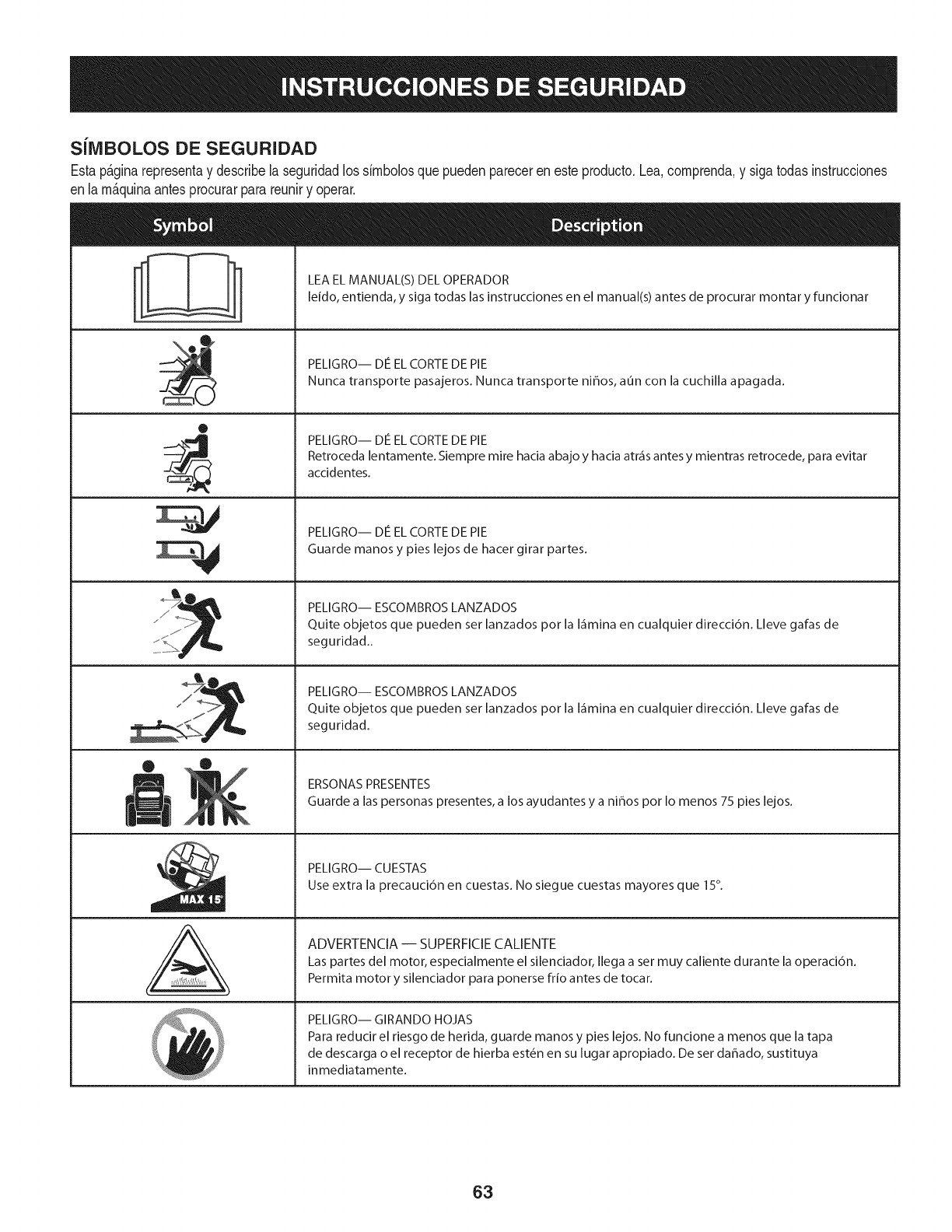
SJlVlBOLOS DE SEGURIDAD
Estap&ginarepresentay describelaseguridadlos simbolosquepuedenpareceren esteproducto.Lea,comprenda,y sigatodasinstrucciones
enla m_quinaantesprocurarparareuniry operar.
0
AL
LEA EL MANUAL(S) DEL OPERADOR
leido, entienda, y siga todas las instrucciones en el manual(s) antes de procurar montar y funcionar
PELIGRO-- DE EL CORTE DE PIE
Nunca transporte pasajeros. Nunca transporte ni_os, aun con la cuchilla apagada.
PELIGRO-- DE EL CORTE DE PIE
Retroceda lentamente. Siempre mire hacia abajo y hacia atr_is antes y mientras retrocede, para evitar
accidentes.
PELIGRO-- DE EL CORTE DE PIE
Guarde manos y pies lejos de hacer girar partes.
PELIGRO-- ESCOMBROS LANZADOS
Quite objetos que pueden set lanzados pot la I_imina en cualquier direcci6n. Lleve galas de
seguridad..
PELIGRO-- ESCOMBROS LANZADOS
Quite objetos que pueden set lanzados pot la I_imina en cualquier direcci6n. Lleve galas de
seguridad.
ERSONAS PRESENTES
Guarde a las personas presentes, a los ayudantes y a ni_os pot Io menos 75 pies lejos.
PELIGRO-- CUESTAS
Use extra la precauci6n en cuestas. No siegue cuestas mayores que 15°.
ADVERTENCIA -- SUPERFICIE CALIENTE
Las partes del motor, especialmente el silenciador, Ilega a set muy caliente durante la operaci6n.
Permita motor y silenciador para ponerse frio antes de tocar.
PELIGRO-- GIRANDO HOJAS
Para reducir el riesgo de herida, guarde manos y pies lejos. No funcione a menos que la tapa
de descarga o el receptor de hierba est_n en su lugar apropiado. De ser dahado, sustituya
inmediatamente.
63
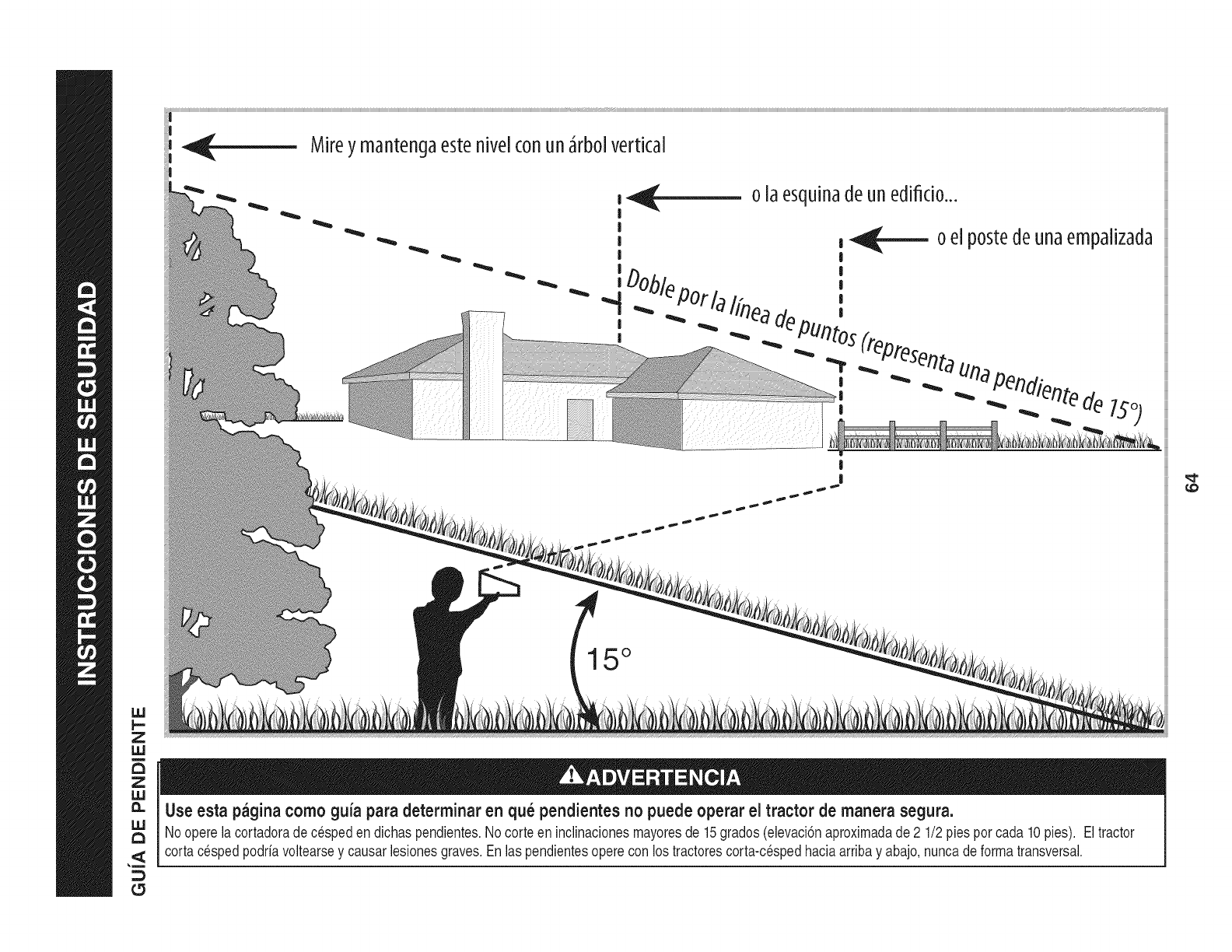
_- Mireymantengaestehive[conunJrbo[vertical
Z
IJJ
o[aesqu[nadeunedifido...
15 °
Use esta pagina como guia para determinar en qu_ pendientes no puede operar el tractor de manera segura.
Nooperelacortadoradecespeden dichaspendientes.Nocorteen inclinacionesmayoresde 15grados(elevaci6naproximadade 2 1/2 piesporcada 10pies). Eltractor
cortacespedpodriavoltearsey causarlesionesgraves.Enlas pendientesoperecon los tractorescorta-cespedhaciaarribay abajo,nuncade formatransversal.
£5
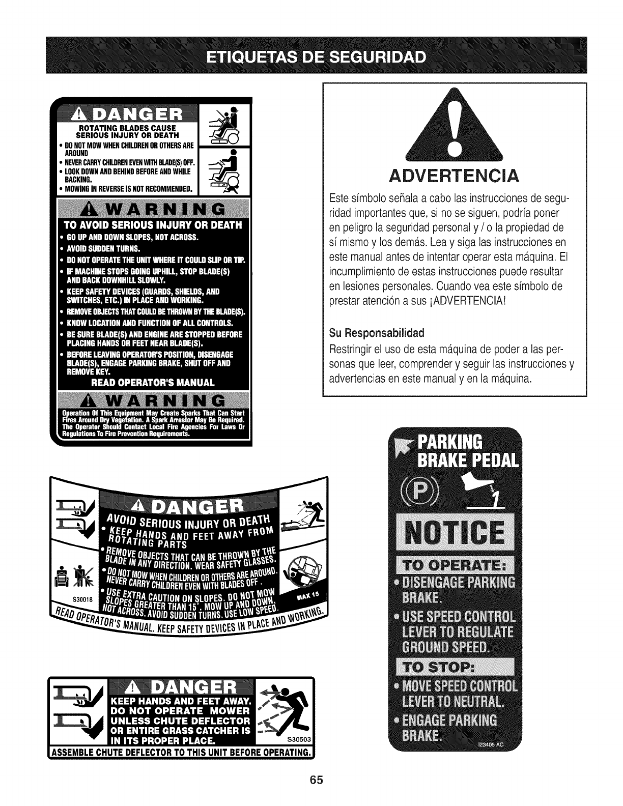
ROTATING BLADES CAUSE
SERIOUS INJURY OR DEATH
DONOTMOWWHENCHILDRENOROTHERSARE
AROUND
NEVERCARRYCHILDRENEVENWITHBLADE(S)OFF.
LOOKDOWNANDBEHINDBEFOREANDWHILE
BACKING.
MOWINGINREVERSEISNOTRECOMMENDED. ADVERTENCIA
Este simbolo seRalaa cabo las instrucciones de segu-
ridad importantesque, si no se siguen, podria poner
en peligro la seguridad personal y /o la propiedad de
si mismoy los dem,_s.Lea y siga las instrucciones en
este manual antes de intentaroperar esta m_tquina.El
incumplimientode estas instruccionespuede resultar
en lesionespersonales.Cuando vea este simbolo de
prestar atenci6na sus iADVERTENCIA!
Su Responsabilidad
Restringirel uso de esta ma.quinade poder a las per-
sonas que leer,comprender y seguir las instruccionesy
advertenciasen este manualyen la m,_quina.
65
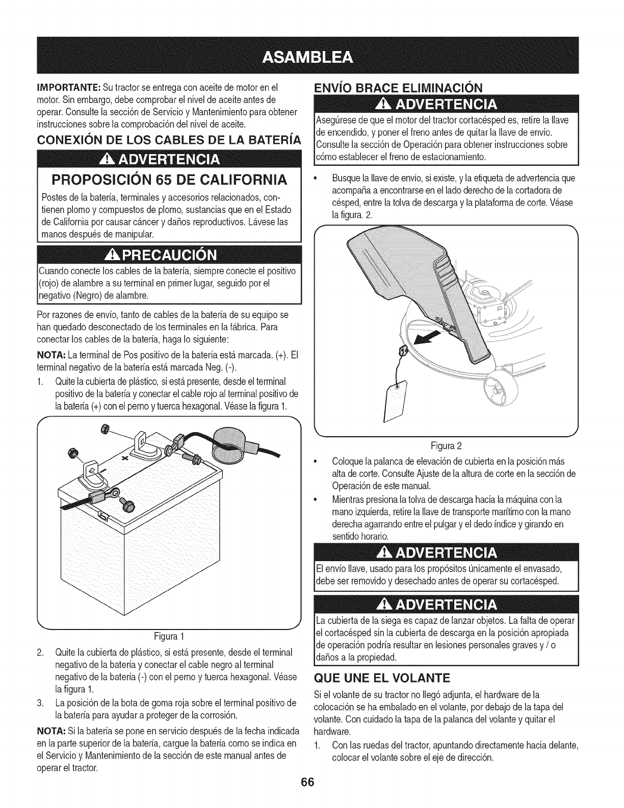
IMPORTANTE: Sutractorse entregaconaceitedemotoren el
motor.Sinembargo,debecornprobarel niveldeaceiteantesde
operar.Consultela secci6nde Servicioy Mantenirnientoparaobtener
instrucdonessobrelacornprobad6ndelnivelde aceite.
CONEXION DE LOS CABLES DE LA BATERIA
PROPOSlClON 65 DE CALIFORNIA
Postesdela bateria,terrninalesy accesoriosrelacionados,con-
fienen plornoy cornpuestosde plorno,sustanciasqueen el Estado
de Californiaporcausarc_.ncery dafiosreproducfivos.L_.veselas
rnanosdespu6sde rnanipular.
Cuandoconecteloscablesde la bateria,siernpreconecteel posifivo
I(rojo)dealarnbrea su terminalenprimerlugar,seguidoporel
pgafivo (Negro)dealarnbre.
Porrazonesde envio,tantodecablesde la bateriade su equipose
hanquedadodesconectadode los terrninalesen laf_.brica.Para
conectarlos cablesde la bateria,hagaIo siguiente:
NOTA: La terminalde Pospositivode la bateriaest,.rnarcada.(+).El
terminalnegativode labateriaest&rnarcadaNeg.(-).
1. Quitela cubiertadepl&stico,si est&presente,desdeelterminal
positivode labateriay conectarelcablerojoalterminalpositivode
Jabateria(+)conel pernoy tuercahexagonal.Veaselafigura1.
f --,,
ENVlO BRACE ELllVIINACI(SN
AsegQresedequeel motordel tractorcortacespedes, retirelaIlave
de encendido,y ponerel frenoantesde quitarla Ilavedeenvio.
IConsultela secci6nde Operaci6nparaobtenerinstruccionessobre
lc6rnoestablecerel frenode estacionarniento.
Busquela Ilavedeenvio,siexiste,y laetiquetadeadvertenciaque
acornpafiaa encontrarseenel ladoderechode lacortadorade
cesped,entrelatolvadedescargay laplataforrnadecorte.Vease
la figura.2.
Figura1
2. Quitelacubiertadepl_.stico,si est,.presente,desdeel terminal
negativode la bateriay conectarel cable negroal terminal
negativode la bateria(-) con elpernoy tuercahexagonal.V6ase
lafigura 1.
3. La posici6nde la botadegornarojasobreel terminalpositivode
la bateriaparaayudara protegerde lacorrosi6n.
NOTA: Si labateriase poneenserviciodespuesde la fechaindicada
en lapartesuperiorde la bateria,carguela bateriacornose indicaen
el Servicioy Mantenirnientode la secci6ndeeste manualantesde
operarel tractor.
Figura2
Coloquelapalancadeelevaci6ndecubiertaen laposici6nrn_.s
alta decorte.ConsulteAjustede laalturade corteenlasecci6nde
Operaci6ndeestemanual.
Mientraspresionalatolvadedescargahaciala rn_.quinaconla
rnanoizquierda,retirela Ilavedetransporternaritirnoconla rnano
derechaagarrandoentreel pulgary el dedoindicey girandoen
sentidohorario.
ElenvioIlave,usadoparalos prop6sitosQnicarnenteel envasado,
debeser rernovidoy desechadoantesde operarsu cortacesped.
Lacubiertade lasiegaes capazdelanzarobjetos.La faltade operar
el cortac6spedsin lacubiertade descargaen la posici6napropiada
de operaci6npodriaresultarenlesionespersonalesgravesy /o I
ldafiosa a propedad. j
QUE UNE EL VOLANTE
Si el volantede su tractornoIleg6adjunta,el hardwaredela
colocaci6nse haernbaladoenel volante,pordebajode latapa del
volante.Con cuidadola tapade lapalancadelvolantey quitarel
hardware.
1. Con las ruedasdeltractor,apuntandodirectarnentehaciadelante,
colocarel volantesobreeleje dedirecci6n.
66
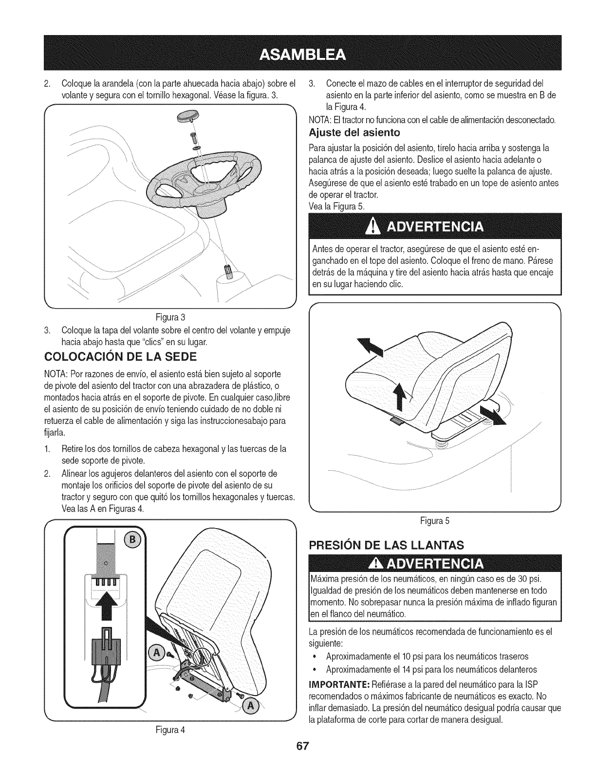
2. Coloquela arandela(con la parteahuecadahaciaabajo)sobreel
volantey seguracon el tornillohexagonal.Wase la figura.3.
f -,
Figura3
3. Coloquela tapadelvolantesobreel centrodelvolantey empuje
haciaabajohastaque"clics"en su lugar.
COLOCAClON DE LA SEDE
NOTA:Porrazonesde envfo,el asientoest,.biensujetoalsoporte
depivotedel asientodeltractorcon unaabrazaderadepl_.stico,o
montadoshaciaatr_.sen elsoportede pivote.Encualquiercaso,libre
el asientode su posici6ndeenvfoteniendocuidadodenodobleni
retuerzael cablede alimentaci6ny sigalas instruccionesabajopara
fijarla.
1. Retirelos dostornillosde cabezahexagonaly lastuercasdela
sedesoportede pivote.
2. Alinearlosagujerosdelanterosdel asientoconel soportede
montajelosorificiosdelsoportede pivotedelasientode su
tractory segurocon quequit6los tomilloshexagonalesy tuercas.
Vealas A en Figuras4.
f-
Figura4
3. Conecteel rnazode cablesen el interruptorde seguridaddel
asientoen la parteinferiordelasiento,comose muestraen Bde
laFigura4.
NOTA:Eltractornofuncionaconel cabledealimentaci6ndesconectado.
Ajuste del asiento
Paraajustarla posici6ndel asiento,firelohaciaarribay sostengala
palancadeajustedel asiento.Desliceel asientohaciaadelanteo
haciaatr_.sa la posici6ndeseada;luegosueltela palancadeajuste.
AsegQresedequeel asientoest_trabadoen untopede asientoantes
de operarel tractor.
Veala Figura5.
Antesde operarel tractor,asegQresede queelasientoest_en-
ganchadoenel topedel asiento.Coloqueel frenode mano.P_.rese
detr_.sde la m_.quinay tire delasientohaciaatr_.shastaqueencaje
en su lugarhaciendoclic.
Figura5
PFIESl0N DE LAS LLANTAS
M_.ximapresi6nde los neum_.ticos,en ning_ncasoes de30 psi.
Igualdadde presi6nde los neum_.ticosdebenmantenerseen todo
momento.Nosobrepasarnuncalapresi6nm_.ximade infiadofiguran
len e f anco de neum_.tco.
Lapresi6nde los neum_.ticosrecomendadade funcionamientoes el
siguiente:
• Aproximadamenteel 10psi paralos neum_.ticostraseros
• Aproximadamenteel 14psi paralos neum_.ticosdelanteros
IMPORTANTE: Refi_rasea lapareddel neum_.ticoparala ISP
recomendadoso m_.ximosfabricantede neum_.ticoses exacto.No
inflardemasiado.Lapresi6ndel neum_.ticodesigualpodriacausarque
laplataformade corteparacortarde maneradesigual.
67
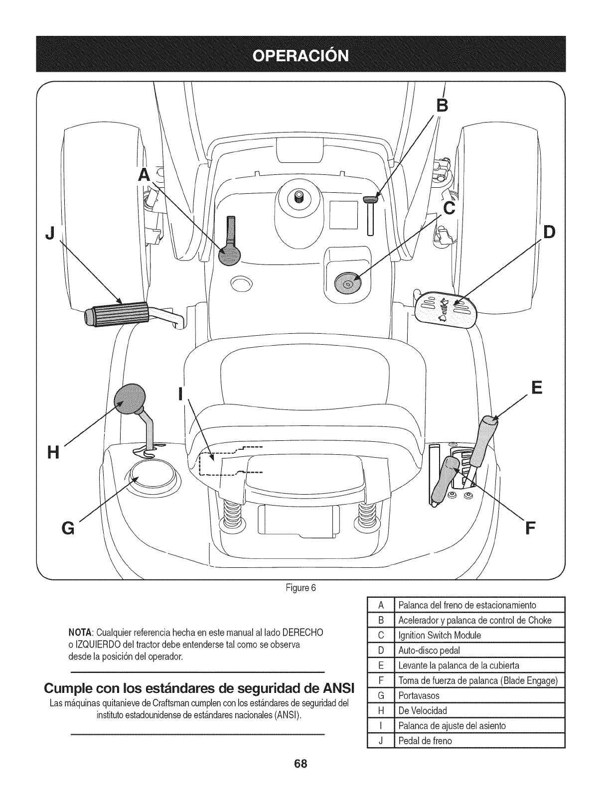
J
E
Figure6
NOTA:Cualquierreferenciahechaenestemanualal ladoDERECHO
o IZQUIERDOdeltractordebeentendersetal comose observa
desde laposici6ndeloperador.
Curnple con los est_ndares de seguridad de ANSI
Lasm_.quinasquitanievedeCraftsmancumplenconlosest_.ndaresdeseguridaddel
institutoestadounidensedeest_.ndaresnacionales(ANSI).
D
A Palancadelfreno de estacionamiento
B Aceleradory palancade controldeChoke
C IgnitionSwitchModule
D Auto-discopedal
E Levantelapalancade la cubierta
F Tomadefuerzade palanca(BladeEngage)
G Portavasos
H DeVelocidad
I Palancade ajustedelasiento
J Pedalde freno
J
68
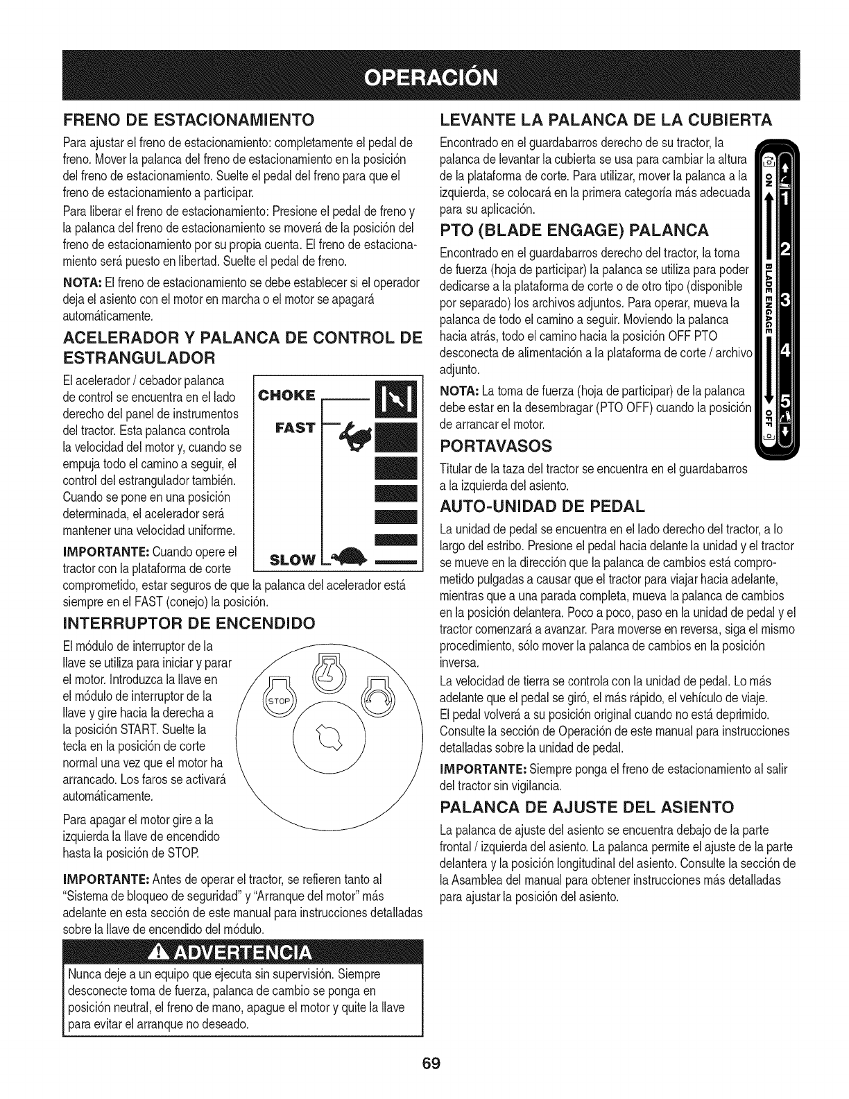
FRENO DE ESTACIONAIVllENTO
Paraajustarel frenodeestacionamiento:completamenteel pedalde
freno.Moverla palancadelfrenode estacionamientoen la posM6n
delfrenode estacionamiento.Suelteel pedaldel frenoparaqueel
frenodeestacionamientoa participar.
Paraliberarelfrenode estacionamiento:Presioneel pedaldefrenoy
la palancadelfrenode estacionamientose mover_,dela posici6ndel
frenodeestacionamientoporsu propiacuenta.Elfrenode estaciona-
mientoser&puestoen libertad.Suelteel pedalde freno.
NOTA: Elfreno deestacionamientose debeestablecersi el operador
dejaelasientocon el motoren marchao el motorse apagar&
autom&ficamente.
ACELERADOR YPALANCA DE CONTROL DE
ESTRANGULADOR
Elacelerador/cebadorpalanca
decontrolseencuentraen el lado
derechodelpanelde instrumentos
deltractor.Estapalancacontrola
la velocidaddelmotory, cuandose
empujatodo elcaminoa seguir,el
controldelestranguladortambi6n.
Cuandose poneenunaposici6n
determinada,el aceleradorser_.
mantenerunavelocidaduniforme.
IMPORTANTE: Cuandoopereel
tractorcon la plataformade corte SLOW
comprometido,estarsegurosde quela palancadelaceleradorest,.
siempreenel FAST(conejo)la posici6n.
INTERRUPTOR DE ENCENDIDO
Elm6dulode interruptorde la
Ilavese utilizaparainiciary parar
el motor.IntroduzcalaIlaveen
el m6dulode interruptorde la
Ilavey girehaciala derechaa
la posici6nSTART.Sueltela
teclaenla posici6ndecorte
normalunavezqueel motorha
arrancado.Losfarosseactivar_.
autom&ticamente.
Paraapagarel motorgirea la
izquierdalaIlavede encendido
hastala posici6ndeSTOR
IMPORTANTE: Antesdeoperarel tractor,se refierentantoal
"Sistemadebloqueode seguridad"y "Arranquedel motor"m_.s
adelanteenestasecci6nde estemanualparainstruccionesdetalladas
sobrela Ilavede encendidodelm6dulo.
Nuncadejea unequipoqueejecutasinsupervisi6n.Siempre
desconectetomade fuerza,palancade cambiose pongaen
posici6nneutral,el frenode mano,apagueel motory quitela Ilave
paraevitarelarranquenodeseado.
LEVANTE LA PALANCA DE LA CUBIERTA
Encontradoenel guardabarrosderechodesu tractor,la
palancadelevantarlacubiertase usaparacambiarlaaltura
de la plataformadecorte. Parautilizar,moverlapalancaa la
izquierda,se colocar_,en laprimeracategoriam_.sadecuada
parasu aplicaci6n.
PTO (BLADE ENGAGE) PALANCA
Encontradoenel guardabarrosderechodeltractor,latoma
de fuerza(hojade participar)la palancase utilizaparapoder
dedicarsea laplataformade corteode otto tipo(disponible
porseparado)los archivosadjuntos.Paraoperar,muevala
palancadetodo el caminoa seguir.Moviendola palanca
haciaatr_.s,todo elcaminohacia laposici6nOFFPTO
desconectade alimentaci6na la plataformade corte/ archivo
adjunto.
NOTA: Latomadefuerza(hojade participar)de lapalanca
debeestarenla desembragar(PTOOFF)cuandola posici6n
de arrancarel motor.
PORTAVASOS
Titulardela tazadeltractorse encuentraenel guardabarros
a la izquierdadel asiento.
AUTO-UNIDAD DE PEDAL
Launidadde pedalse encuentraenel ladoderechodel tractor,a Io
largodelestribo.Presioneel pedalhaciadelantela unidady el tractor
semueveen ladirecci6nquela palancadecambiosest,.compro-
metidopulgadasa causarqueel tractorparaviajarhaciaadelante,
mientrasquea unaparadacompleta,muevala palancade cambios
en la posici6ndelantera.Pocoa poco,pasoen launidadde pedaly el
tractorcomenzar_,a avanzar.Paramoverseen reversa,sigael mismo
procedimiento,s61omoverla palancade cambiosenla posici6n
inversa.
Lavelocidadde tierrase controlacon la unidadde pedal.Lom_.s
adelantequeel pedalsegir6, el m_.sr_.pido,elvehiculode viaje.
Elpedalvolver_,a su posici6noriginalcuandono est,.deprimido.
Consultela secci6nde Operaci6nde estemanualparainstrucciones
detalladassobrela unidadde pedal.
IMPORTANTE: Siemprepongael frenodeestacionamientoal salir
del tractorsin vigilancia.
PALANCA DE AJUSTE DEL ASIENTO
Lapalancade ajustedelasientose encuentradebajode la parte
frontal/izquierda delasiento.La palancapermiteelajustedela parte
delanteray laposici6nlongitudinaldelasiento.Consultelasecci6nde
laAsambleadel manualparaobtenerinstruccionesm_.sdetalladas
paraajustarla posici6ndelasiento.
69
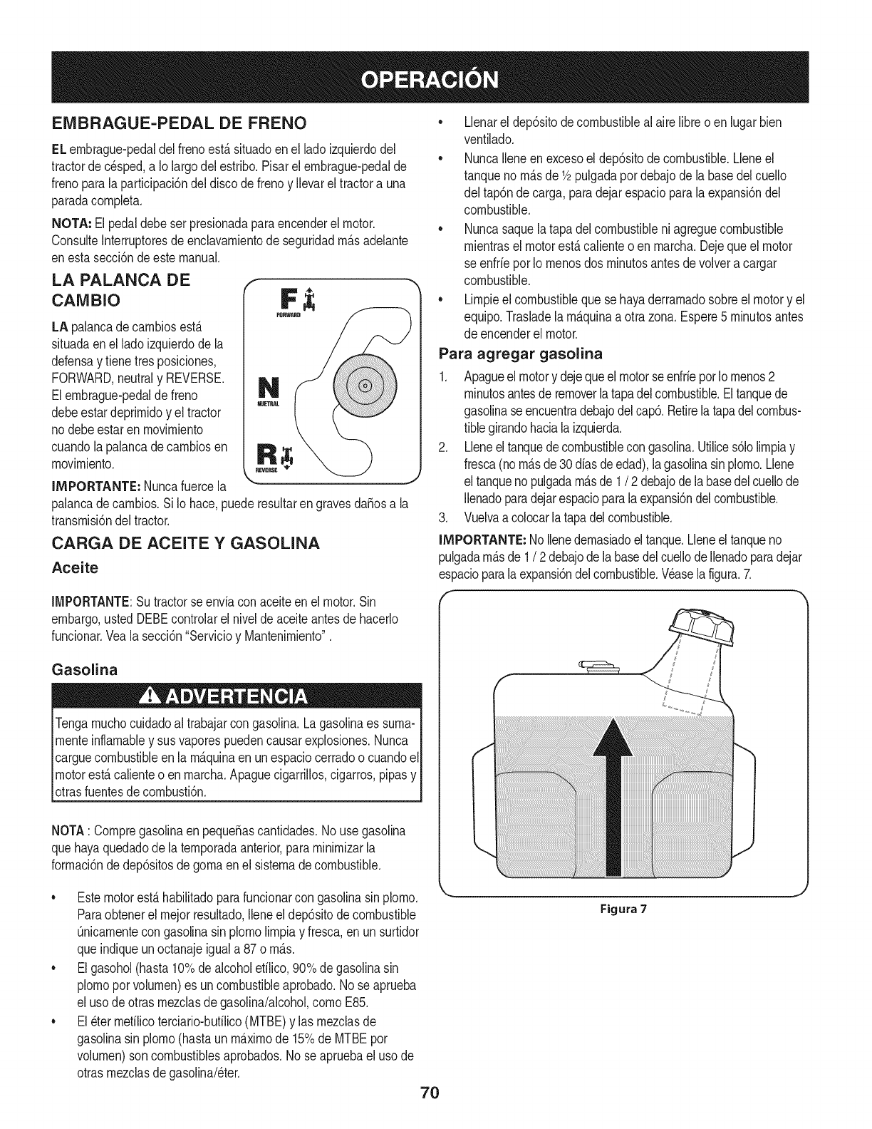
EMBRAGUE-PEDAL DE FRENO
ELembrague-pedaldel frenoest,.situadoen el ladoizquierdodel
tractorde c_sped,a Io largodel estribo.Pisarel embrague-pedalde
frenoparalaparticipaci6ndel discode frenoy Ilevarel tractora una
paradacompleta.
NOTA: El pedaldebeser presionadaparaencenderel motor.
ConsulteInterruptoresdeenclavamientode seguridadm_.sadelante
enestasecci6ndeestemanual.
LA PALANCA DE
CANIBIO
LA palancadecambiosest,.
situadaenel ladoizquierdode la
defensay tienetresposiciones,
FORWARD,neutraly REVERSE.
Elembrague-pedalde freno
debeestardeprimidoy el tractor
nodebeestarenmovimiento
cuandolapalancade cambiosen
movimiento.
IMPORTANTE: Nuncafuercela
palancadecambios.Si Io hace,puederesultarengravesdaSosa la
transmisi6ndel tractor.
CARGA DE ACEITE Y GASOLINA
Aceite
IMPORTANTE:Su tractorse enviacon aceiteen el motor.Sin
embargo,ustedDEBEcontrolarel nivelde aceiteantesde hacerlo
funcionar.Vealasecci6n"Servicioy Mantenimiento".
Gasolina
Tengamuchocuidadoal trabajarcon gasolina.Lagasolinaes suma-
menteinflamabley susvaporespuedencausarexplosiones.Nunca
carguecombustibleenla m_.quinaen unespaciocerradoo cuandoel
motorest,.calienteo en marcha.Apaguecigarrillos,cigarros,pipasy
otrasfuentesde combusti6n.
NOTA: Compregasolinaen pequeSascantidades.No usegasolina
quehayaquedadode latemporadaanterior,paraminimizarla
formaci6nde dep6sitosdegomaenel sistemadecombustible.
•Llenarel dep6sitodecombustibleal airelibreo en lugarbien
ventilado.
• NuncaIleneen excesoel dep6sitode combustible.Lleneel
tanqueno m_.sde 1/2pulgadapordebajode labasedelcuello
del tap6ndecarga,paradejarespacioparalaexpansi6ndel
combustible.
• Nuncasaquelatapadel combustibleniagreguecombustible
mientrasel motorest,.calienteo enmarcha.Dejequeelmotor
se enfrie porIo menosdos minutosantesdevolvera cargar
combustible.
• Limpieel combustibleque sehayaderramadosobreel motory el
equipo.Trasladelam_.quinaa otrazona.Espere5 minutosantes
de encenderel motor.
Para agregar gasolina
1. Apagueel motory dejequeelmotorseenfrieporIomenos2
minutosantesde removerlatapadelcombustible.Eltanquede
gasolinaseencuentradebajodelcap& Retirelatapadelcombus-
tiblegirandohaciala izquierda.
2. Lleneel tanquedecombustiblecongasolina.Utilices61olimpiay
fresca(nom_.sde30diasde edad),lagasolinasinplomo.Llene
el tanquenopulgadam_.sde 1/2 debajode labasedelcuellode
Ilenadoparadejarespacioparala expansi6ndelcombustible.
3. Vuelvaacolocarlatapadelcombustible.
IMPORTANTE:No Ilenedemasiadoel tanque.Lleneeltanqueno
pulgadam_.sde 1/2debajodela basedelcuellode Ilenadoparadejar
espacioparalaexpansi6ndelcombustible.Wase la figura.7.
• Estemotorest,.habilitadoparafuncionarcon gasolinasinplomo.
Paraobtenerel mejor resultado,Ileneel dep6sitodecombustible
Onicamentecongasolinasin plomolimpiay fresca,enun surtidor
queindiqueunoctanajeiguala 87o m_.s.
• Elgasohol(hasta10%dealcoholetilico,90%degasolinasin
plomoporvolumen)es uncombustibleaprobado.No seaprueba
el usode otrasmezclasdegasolina/alcohol,comoE85.
• El_ter mefilicoterciario-butilico(MTBE)y las mezclasde
gasolinasin plomo(hastaun m_.ximode 15%de MTBEpor
volumen)son combustiblesaprobados.No se apruebaeluso de
otrasmezclasdegasolina/eter.
Figura 7
7O
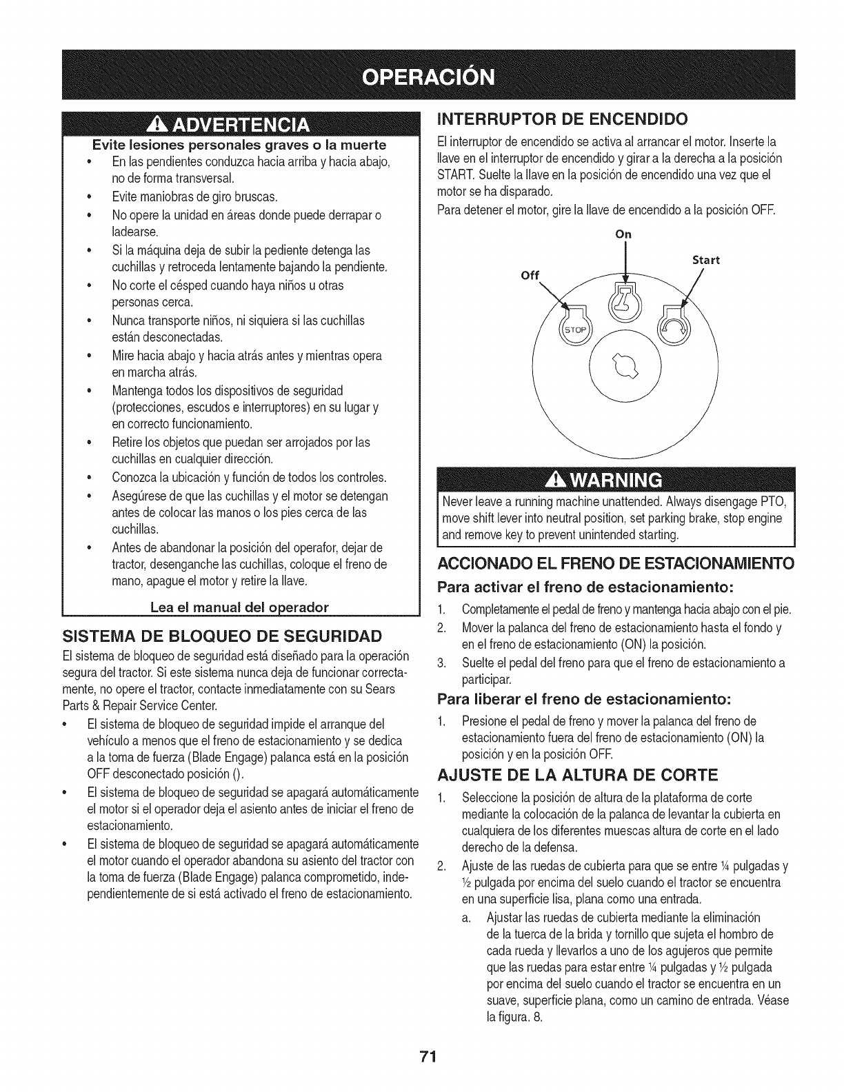
Evite lesiones personales graves o la muerte
•Enlas pendientesconduzcahaciaarribay haciaabajo,
node forrnatransversal.
•Eviternaniobrasde girobruscas.
•No operela unidaden_.reasdondepuedederraparo
ladearse.
•Si larn_.quinadejade subirla pedientedetengalas
cuchillasy retrocedalentarnentebajandolapendiente.
•No corteel c_spedcuandohayaniSosuotras
personascerca.
•NuncatransporteniSos,ni siquierasi lascuchillas
est_.ndesconectadas.
•Mirehaciaabajoy haciaatr_.santesy rnientrasopera
enrnarchaatr_.s.
•Mantengatodoslosdispositivosde seguridad
(protecciones,escudose interruptores)ensu lugary
encorrectofuncionarniento.
•Retirelos objetosquepuedanserarrojadospor las
cuchillasencualquierdirecci6n.
•Conozcala ubicaci6ny funci6nde todoslos controles.
•AsegQresede quelas cuchillasy elmotorsedetengan
antesde colocarlas rnanoso los piescercade las
cuchillas.
• Antesde abandonarlaposici6ndeloperafor,dejarde
tractor,desenganchelascuchillas,coloqueel frenode
rnano,apagueelmotory retirela Ilave.
Lea el manual del oerador
SISTEMA DE BLOQUEO DE SEGURIDAD
Elsisternade bloqueode seguridadest,.dise_adoparala operaci6n
seguradel tractor.Si estesisternanuncadejade funcionarcorrecta-
rnente,no opereel tractor,contacteinrnediatarnentecon suSears
Parts& RepairServiceCenter.
•Elsisternade bloqueode seguridadirnpideel arranquedel
vehiculoa rnenosqueel frenode estacionarnientoy se dedica
a latornadefuerza(BladeEngage)palancaest,.en laposici6n
OFFdesconectadoposici6nO.
•Elsisternade bloqueode seguridadseapagar&autorn&ticarnente
el motorsi el operadordejael asientoantesde iniciarel frenode
estacionarniento.
•Elsisternade bloqueode seguridadseapagar&autorn&ticarnente
el motorcuandoel operadorabandonasuasientodel tractorcon
la tornadefuerza(BladeEngage)palancacornprornetido,inde-
pendienternentede si est,.activadoel frenodeestacionarniento.
INTERRUPTOR DE ENCENDIDO
Elinterruptordeencendidose activaal arrancarel motor.Insertela
Ilaveen el interruptorde encendidoy girara laderechaa la posici6n
START.Sueltela Ilaveenla posici6ndeencendidounavezqueel
motorse hadisparado.
Paradetenerel motor,girela Ilavedeencendidoa laposici6nOFE
On
Start
off
Neverleavea runningmachineunattended.AlwaysdisengagePTO,
moveshift leverinto neutralposition,setparkingbrake,stopengine
and removekeyto preventunintendedstarting.
ACCIONADO EL FRENO DE ESTACIONAMIENTO
Para activar el freno de estacionamiento:
1. Completarnenteelpedaldefrenoy rnantengahaciaabajoconel pie.
2. Moverlapalancadel frenodeestacionarnientohastael rondoy
en elfrenode estacionarniento(ON)la posici6n.
3. Suelteel pedaldelfreno paraqueel frenode estacionarnientoa
participar.
Para liberar el freno de estacionamiento:
1. Presioneel pedalde frenoy moverla palancadelfreno de
estacionarnientofueradelfrenode estacionarniento(ON)la
posici6nyen la posici6nOFE
AJUSTE DE LA ALTURA DE CORTE
Seleccionelaposici6ndealturade la plataforrnadecorte
rnediantelacolocaci6ndela palancade levantarlacubiertaen
cualquieradelos diferentesrnuescasalturadecorteen el lado
derechode la defensa.
Ajustedelas ruedasde cubiertaparaquese entre1Apulgadasy
1/2pulgadapot encirnadel suelocuandoel tractorseencuentra
en unasuperficielisa,planacornounaentrada.
a. Ajustarlas ruedasdecubiertarnediantelaelirninaci6n
de latuercadela briday tornilloquesujetael hornbrode
cada rueday Ilevarlosa unodelos agujerosqueperrnite
que las ruedasparaestarentre1Apulgadasy 1/2pulgada
porencirnadelsuelocuandoel tractorse encuentraen un
suave,superficieplan&cornouncarninode entrada.Wase
lafigura.8.
71
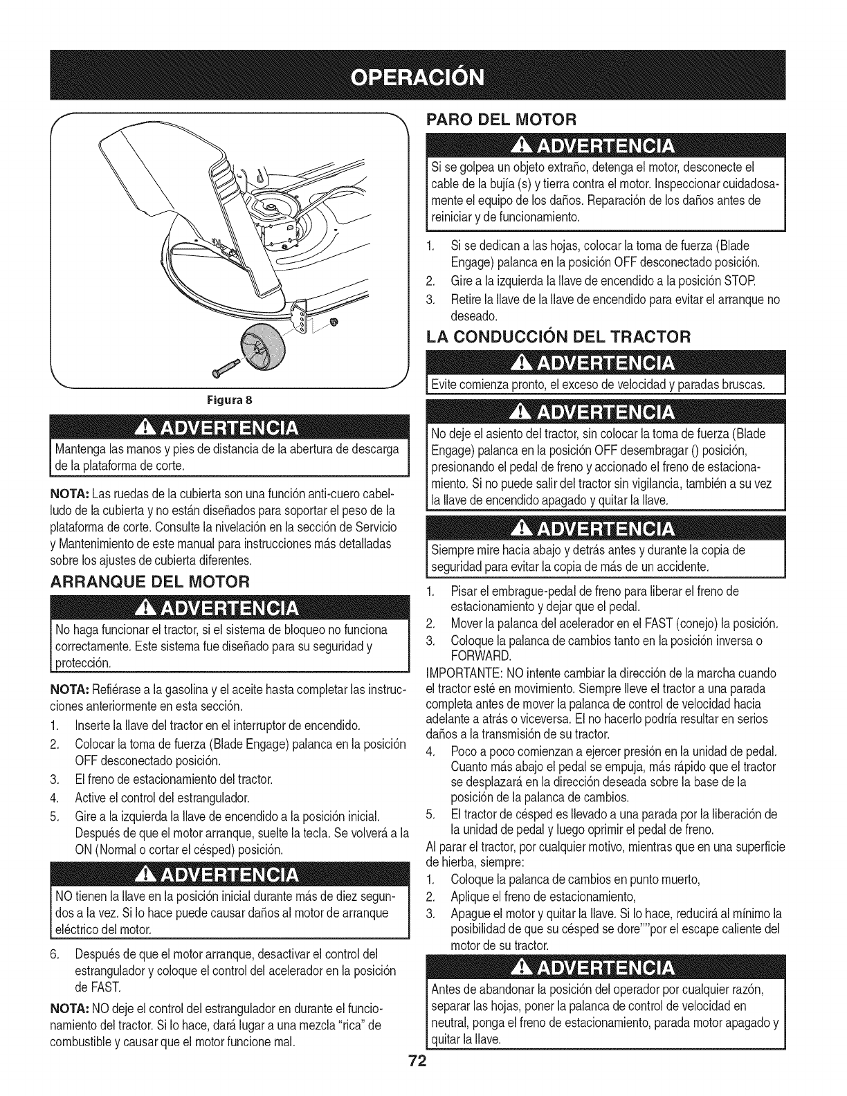
PARO DEL MOTOR
Si se golpeaunobjetoextra,o, detengael motor,desconecteel
cablede la bujfa(s) y tierracontrael motor.Inspeccionarcuidadosa-
rnenteel equipode losda_os.Reparaci6nde losda_osantesde
reiniciary defuncionarniento.
1. Si se dedicanalas hojas,colocarlatornadefuerza(Blade
Engage)palancaen laposici6nOFFdesconectadoposici6n.
2. Girea la izquierdalaIlavedeencendidoa la posici6nSTOR
3. RetirelaIlavede laIlavede encendidoparaevitarelarranqueno
deseado.
LA CONDUCCION DEL TRACTOR
Figura 8
Mantengalasrnanosy piesde distanciadela aberturade descarga
de la plataforrnadecorte.
NOTA: Las ruedasde la cubiertasonunafunci6nanti-cuerocabel-
ludode lacubiertay noest_.ndiseSadosparasoportarel pesode la
plataforrnade corte.Consultelanivelaci6nen la secci6nde Servicio
y Mantenirnientode estemanualparainstruccionesrn_.sdetalladas
sobrelos ajustesdecubiertadiferentes.
ARRANQUE DEL MOTOR
No hagafuncionarel tractor,si el sisternade bloqueonofunciona
correctarnente.EstesisternaruediseSadoparasu seguridady
protecci6n.
NOTA: Refi_rasea lagasolinay elaceitehastacornpletarlas instruc-
cionesanteriorrnenteenesta secci6n.
1. InsertelaIlavedeltractoren elinterruptorde encendido.
2. Colocarlatornade fuerza(BladeEngage)palancaen la posici6n
OFFdesconectadoposici6n.
3. Elfrenode estacionarnientodel tractor.
4. Activeel controldel estrangulador.
5. Girea laizquierdala Ilavede encendidoa laposici6ninicial.
Despu_sdequeel motorarranque,sueltela tecla.Sevolver_,a la
ON (Normalo cortarel cesped)posici6n.
NOtienenla Ilaveen laposici6ninicialdurantern_.sdediez segun-
dosa la vez.Si Io hacepuedecausardaSosal motorde arranque
el_ctricodel motor.
6. Despu_sdequeel motorarranque,desactivarelcontroldel
estranguladory coloqueel controldel aceleradoren laposici6n
de FAST.
NOTA: NO dejeelcontroldel estranguladorenduranteel funcio-
narnientodeltractor.Si Iohace,dar_.lugara unarnezcla"rica"de
combustibley causarqueel motorfuncionernal.
Evitecornienzapronto,el excesodevelocidady paradasbruscas.
Nodejeel asientodel tractor,sin colocarla tornadefuerza(Blade
Engage)palancaen laposici6nOFFdesernbragar0 posici6n,
presionandoel pedalde frenoy accionadoel frenodeestaciona-
rniento.Sino puedesalirdeltractorsin vigilancia,tarnbi_na suvez
la Ilavedeencendidoapagadoy quitarla Ilave.
Siernpremire haciaabajoy detr_.santesy durantelacopiade
seguridadparaevitarla copiadern_.sde unaccidente.
1. Pisarel ernbrague-pedaldefrenoparaliberarel frenode
estacionarnientoy dejarqueel pedal.
2. Moverla palancadel aceleradorenel FAST(conejo)laposici6n.
3. Coloquelapalancade carnbiostantoenla posici6ninversao
FORWARD.
IMPORTANTE:NOintentecarnbiarladirecci6nde larnarchacuando
el tractorest_enrnovirniento.SiernpreIleveel tractora unaparada
cornpletaantesdemoverla palancade controldevelocidadhacia
adelantea atr_.soviceversa.El nohacerlopodriaresultarenserios
da_osa la transrnisi6nde su tractor.
4. Pocoa pococornienzana ejercerpresi6nenla unidadde pedal.
Cuantorn_.sabajoel pedalse ernpuja,rn_.sr_.pidoqueeltractor
se desplazar_,en ladirecci6ndeseadasobrela basedela
posici6nde lapalancadecarnbios.
5. Eltractorde c_spedes Ilevadoa unaparadaporla liberaci6nde
la unidadde pedaly luegooprirnirel pedaldefreno.
AI pararel tractor,porcualquierrnotivo,rnientrasqueen unasuperficie
de hierba,siernpre:
1. Coloquelapalancade carnbiosen puntornuerto,
2. Apliqueel frenodeestacionarniento,
3. Apagueel motory quitar laIlave.Si Io hace,reducir_,al rninirnola
posibilidaddeque sucespedsedore'"'porel escapecalientedel
motorde su tractor.
Antesde abandonarla posici6ndel operadorporcualquierraz6n,
separarlashojas,ponerla palancadecontroldevelocidaden
neutral,pongael frenode estacionarniento,paradamotorapagadoy
quitarla Ilave.
72
CONDUCCI6N EN LAS LADERAS INVOLUCRAR A LOS BLADES
Refierenal anchodela pendienteen la seguridadde las pr_.cticasde
operaci6nirnportantesecci6ndelmanualparaayudara deterrninar
zonasde laderadondepuedeoperareltractorcon totalseguridad.
Nocorteel cespeden pendientesconunainclinaci6nde rn_.sde 15
grados(unaurnentodeaproxirnadarnente2-1/2pies cada 10pies).
Eltractorpuedevolcary causarlesionesgraves.
• Corteel c_spedy las pendientes,nuncatransversal.
• Tengaextrernaprecauci6nalcarnbiarde direcci6nen las
pendientes.
• Watchparalos agujeros,grietas,baches,piedrasu otrosobjetos
ocultos.Terrenoirregularpuederevertirla rn_.quina.Elcesped
altopuedeocultarobst_.culos.
• Evitegirarcuandosecirculaporunapendiente.Si unavez,debe
hacerse,a suvez porlapendiente.El regresode unapendiente
aurnentala posibilidadde un rollover.
• Evitedetenersecuandoseconduceporunapendiente.Sies
necesariodetenerrnientrasse conducepot unapendiente,
puestaen rnarchasinproblernasy con cuidadoparareducirla
posibiNdadde volteareltractorhaciaatr_.s.
Participaci6ndelatornade fuerza(BladeEngage)lastransferenciasde
energfaala plataforrnadecorteo deotrotipo(disponibleporseparado)
losarchivosadjuntos.Paraparticiparde lashojas,hagaIosiguiente:
1. Moverlapalancade controldelaceleradora la r_.pida(conejo)la
posici6n.
2. Sujetela tornade fuerza(BladeEngage)y girarla palancade
todo elcarninoa seguira los novios(ON) laposici6n.
3. Mantengala palancadel aceleradoren el FAST(conejo)la
posici6nparael usorn_.seficientede laplataforrnade corteo de
otro tipo (disponiblepor separado)los archivosadjuntos.
NOTA: Elmotorse apagar_,autom_.ticarnentesi latornadefuerza
est,.comprornetidocon la palancadecarnbiosen la posici6nde
rnarchaatr_.scon laNavedeencendidoen la posici6nON.
USO DE LA CUBIERTA DE LEVANTE LA
PALANCA DE
Paraelevarla plataforrnade corte,moverla palancadeelevaci6nde
cubiertaa la izquierda,luegosecolocaen laranurarn_.sadecuada
parasu apNcaci6n.ConsulteAjustelaalturade corteanteriorrnenteen
estasecci6n.
73
CORTAR
Paraayudara evitarelcontactocon lacuchillao unalesi6nen
elobjetolanzado,Mantengaa los espectadores,losayudantes,
los niSosy las mascotasporIo menos75piesde distandade la
m_.quinamientrasest,.enfundonamiento.Paradade lam_.quina,si
alguienentraenel _.rea.
La siguienteinformaci6nser_.Qfilcuandose ufilizala plataformade
corteconsu tractor:
Plande su patr6nde corteparaevitarla descargade materiales
hada lascarreteras,aceras,transeQntes,etc. Adem_.s,evitematerial
quese descargacontraunaparedo unaobstrucd6nque puede
causaralta materiala rebotarhaciael operador.
FAROS
• LasI&mparasest&nONcuandoel motordeltractorse est&
ejecutando.
• Laslucesseapagacuandola Ilavede contactose muevea la
posici6nSTOE
• Nocorteel c6speda la velocidadde terrenoelevado,especial-
mentesi se ha instaladoun kitde mantilloo colectorde cesped.
• Paraobtenerlos mejoresresultadosse recomiendaquelas
dos primerasvueltassecortar&conla aprobaci6nde lagesti6n
arrojadohaciael centro.Traslasdos primerasvueltas,invertirel
sentidode lanzarla descargahaciael exteriordela balanzade
corte.Estoledar&unamejoraparienciaalcesped.
• Nocorteel cespeddemasiadocorto. Pastocortoinvitacrec-
imientodemalashierbasy los amarilloscon rapidezen el tiempo
seco.
• Cortarel c6spedsiemprese debehacercon el motora todogas.
• Bajolascondicionesm_.spesadas,puedesernecesariovolversobre
lazonadelcorteporsegundavezparaobteneruncortelimpio.
• NOintentecortarespesamalezay malashierbasy elpastomuyalto.
Sutractorest&diseSadoparacortarelc6sped,uncepillonoest&claro.
• Mantengalas cuchillasafiladasy sustituirlascuchillasencaso
dedesgaste.ConsulteHojasdecorteenel servicioy la secd6n
Mantenimientodeeste manualdeinstruccionesdeafilar lahoja
adecuada.
74
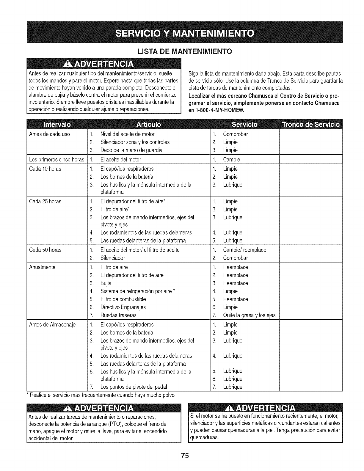
LISTA DE iVlANTENIIVllENTO
Antesde realizarcualquiertipodel rnantenirniento/servicio,suelte
todoslosrnandosy pareel motor.Esperehastaquetodaslaspartes
de rnovirnientohayanvenidoa unaparadacornpleta.Desconecteel
alarnbrede bujiay b_.selocontrael motorparaprevenirel cornienzo
involuntario.SiernpreIlevepuestoscristalesinastillablesdurantela
operaci6no realizandocualquierajusteo reparaciones.
Sigala listade rnantenirnientodadaabajo.Estacartadescribepautas
de servicios61o.Usela colurnnade Troncode Servicioparaguardarla
pistade tareasdernantenirnientocornpletadas.
Localizarel rn_scercanoChamuscael Centrode Servicio o pro-
gramar el servicio,simplementeponerseen contactoChamusca
en 1-800-4-MY-HOME®.
Antesde cadauso
Los prirneroscincohoras
Cada 10horas
Cada25horas
Cada50horas
Anualrnente
Antesde Alrnacenaje
1. Niveldelaceitede motor
2. Silenciadorzonay loscontroles
3. Dedodela rnanodeguardia
1. Elaceitedel motor
1. EIcap6/Iosrespiraderos
2. Losbornesdela bateria
3. Loshusillosy larn_nsulainterrnediade la
plataforrna
1. Eldepuradordelfiltrode aire*
2. Filtrode aire*
3. Losbrazosde rnandointerrnedios,ejes del
pivotey ejes
4. Los rodarnientosde las ruedasdelanteras
5. Las ruedasdelanterasde la plataforrna
1. Elaceitedel motor/el filtrodeaceite
2. Silenciador
1. Filtrode aire
2. Eldepuradordelfiltrode aire
3. Bujia
4. Sisternaderefrigeraci6nporaire*
5. Filtrode combustible
6. DirectivoEngranajes
7. Ruedastraseras
1. EIcap6/Iosrespiraderos
2. Loshomesdela bateria
3. Losbrazosde rnandointerrnedios,ejes del
pivotey ejes
4. Los rodarnientosdelas ruedasdelanteras
5. Las ruedasdelanterasde la plataforrna
6. Loshusillosy larn_nsulainterrnediade la
plataforrna
7. Lospuntosde pivotedel pedal
Realiceel serviciorn_.sfrecuenternentecuandohayarnuchopolvo.
Antesde realizartareasde mantenirnientoo reparaciones,
desconectela potenciadearranque(PTO),coloqueel frenode
rnano,apagueel motory retirela Ilave,paraevitarelencendido
accidentaldel motor.
.
2.
3.
1.
1.
2.
3.
Cornprobar
Lirnpie
Lirnpie
Carnbie
Lirnpie
Lirnpie
Lubrique
1. Lirnpie
2. Lirnpie
3. Lubrique
4. Lubrique
5. Lubrique
1. Carnbie/reernplace
2. Cornprobar
1. Reernplace
2. Reernplace
3. Reernplace
4. Lirnpie
5. Reernplace
6. Lirnpie
7. Quitelagrasay los ejes
1. Lirnpie
2. Lirnpie
3. Lubrique
4. Lubrique
5. Lubrique
6. Lubrique
Z Lubrique
Si el motorse ha puestoen funcionarnientorecienternente,el motor,
silenciadory las superficiesrnet_.licascircundantesestar_.ncalientes
Iy puedencausarquernadurasa la piel.Tengaprecauci6nparaevitar
[quernaduras.
75
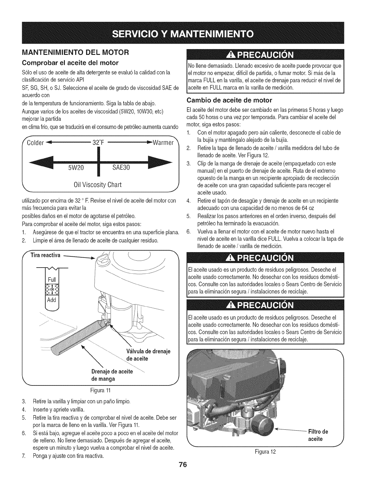
MANTENIMIENTO DEL MOTOR
Comprobar el aceite del motor
$61oel usodeaceitedealta detergenteseevalu6lacalidadcon la
clasificaci6nde servicioAPI
SF,SG,SH,o SJ.Seleccioneel aceitede gradode viscosidadSAEde
acuerdocon
de laternperaturadefuncionarniento.Sigalatablade abajo.
Aunquevariosdelos aceitesdeviscosidad(5W20,10W30,etc)
rnejorarla partida
enclirnafifo,quese traducirAenelconsurnodepetr61eoaurnentacuando
Colder "< 32°F _Warmer
Oil Viscosity Chart
utilizadoporencirnade32 oE Reviseel niveldeaceitedelmotorcon
rnAsfrecuenciaparaevitarla
posiblesdafiosen el motordeagotarseel petr61eo.
Paracornprobarel aceitedel motor,sigaestospasos:
1. AsegOresedequeel tractorse encuentraen unasuperficieplana.
2. Lirnpieel _.reade Ilenadode aceitede cualquierresiduo.
f Tira reactiva
V_lvulade drenaje
de aceite
Drenajede aceite
de manga
Figura11
3. Retirela variNay lirnpiarconun patioNrnpio.
4. Insertey aprietevarilla.
5. Retirela tira reactivay de cornprobarel nivelde aceite.Debeser
porla rnarcade Ilenoen lavarilla.VerFigura11.
6. Siest_ bajo,agregueel aceitepocoa pocoen elaceitedelmotor
de reNeno.1/oNenedernasiado.Despu_sdeagregarel aceite,
espereunrninutoy luegovuelvaacornprobarel nivelde aceite.
7. Pongay ajustecon tira reactiva.
76
No Nenedernasiado.Llenadoexcesivodeaceitepuedeprovocarque
elmotornoernpezar,diffcilde partida,o furnarmotor.Si rn_sde la
rnarcaFULLen lavarilla,el aceitede drenajeparareducirel nivelde
aceiteen FULLrnarcaen lavarillade rnedici6n.
Cambio de aceite de motor
Elaceitedel motordebesetcarnbiadoen las prirneras5 horasy luego
cada 50horaso unavezporternporada.Paracarnbiarel aceitedel
motor,sigaestospasos:
1. Con el motorapagadoperoaOncaliente,desconecteelcablede
la bujfay rnant_ngaloalejadodela bujfa.
2. Retirelatapa deIlenadodeaceite/varillarnedidoradeltubo de
Nenadode aceite.Vet Figura12.
3. Clip de larnangadedrenajedeaceite(ernpaquetadocon este
manual)enel puertode drenajedeaceite.Rutadeel extrerno
opuestode larnangaenun recipienteapropiadode recolecci6n
de aceitecon unagrancapacidadsuficientepararecogerel
aceiteusado.
4. Retireel tap6nde desagOey drenajedeaceiteenun recipiente
adecuadocon unacapacidaddeno rnenosde64 oz
5. Realizarlos pasosanterioresenel ordeninverso,despu_sdel
petr61eohaterrninadola evacuaci6n.
6. Vuelvaa Nenarel motorconel aceitede motornuevohastael
nivelde aceiteen lavarilladice FULL.Vuelvaa colocarlatapa de
Ilenadode aceite/varillade rnedici6n.
Elaceiteusadoes un productode residuospeligrosos.Desecheel
aceiteusadocorrectarnente.1/odesecharcon los residuosdorn_sti-
cos.Consultecon lasautoridadeslocaleso SearsCentrodeServicio
_aralaeNrninaci6nsegura/instalacionesde reciclaje.
Elaceiteusadoes un productode residuospeligrosos.Desecheel
aceiteusadocorrectarnente.1/odesecharcon los residuosdorn_sti-
cos.Consultecon lasautoridadeslocaleso SearsCentrodeServicio
[para a e rnnac6n segura/nstaac onesde recc aje.
Figura12

Fuel Filter
• Mantengalagasolinalejosdechispas,llamas,lucespiloto,el
calor,y otrasfuentesde ignici6n.
• Cornpruebelas lineasde combustible,eltanque,la tapay los
accesoriosconfrecuenciaparadetectarrajadurasoescapes.
Reernplazarsi es necesario.
• Antesde reernplazarel filtrodecombustible,vaciarel tanquede
combustiblesegQnlas instruccionesdeabajo.
• No fugadecombustiblecuandoel motorest,.caliente.Dejeque
el motordetiernpoadecuadoparaenfriar.Evacuarelcombustible
enun recipienteaprobadoal airelibre,lejosde llamasabiertas.
• Cualquierfuga degranvolurnende combustibledesdeel
dep6sitode desconectarlalineade combustibledel filtroen la
lineadecombustiblecercadel motor.
• Quitela lineadecombustibledela LN-ladode la linea(ladohacia
el tanquede combustible)delfiltrode combustible.
• Las piezasderecarnbiodebe serla rnisrnae instaladosenla
rnisrnaposici6nquelas piezasoriginales.
• Si sederrarnacombustible,esperehastaque seevaporaantes
dearrancarel motor.
• Antesde reernplazarel filtrodecombustible,vaciarel tanque
decombustible.DeIocontrario,el combustiblepuedefiltrarsey
provocarun incendioo unaexplosi6n.
Paradrenarel combustible:
1. Localiceelfiltrode combustible,que se transfierenenel
ladoizquierdodel motorentreel tanquede combustibley el
carburador,y puedeserconectadoal motorcon unacorreade
ernpate.Cortarla correadela corbata,si est,.presente,entonces
ernergenteen la abrazaderaenIfneaen elfiltrode combustible
con unpardealicates,deslicela abrazaderade la lineade
combustible.Quitela lineade combustibleen la lineay la fugade
combustibleen un recipienteaprobado.
Paracambiarel filtro de combustible:
1. Usepinzasparaapretarlaspesta_asdela abrazadera(el lado
dela lineadefueradel filtrodecombustible),a continuaci6n,
deslicela abrazaderalejosdelfiltrode combustible.Twisty tirar
dela lineadecombustiblefueradelfiltrode combustible.Wase
la figura13.
2. Cornpruebelas lineasde combustibleparalasgrietaso fugas.
Reernplazarsi es necesario.
f
Clamp Fuel
Line
Tab
3. Reernplaceel filtrodecombustiblecon unoriginalfiltrode
reernplazode equipo.ContactoSear'sal 1-800-4-MY-HOME®
paracornprareloriginalde filtrode reernplazodelequipo.
4. Asegurelas lineasde combustiblecon laspinzas.
LIIVIPIADOR DE AIRE
Si losfiltros,o cubiertasnoest_.ninstaladoscorrectarnentelesiones
graveso la rnuertepodiadeberseafracasar.Notratedeencenderel
motorcon lasretiren.
Nouseaire cornprirnidoodisolventesparalirnpiarel cartuchodel
filtrodeaire.
Elsisternade filtrodeaire utilizauncartuchocilindrico.Esternodelo
tarnbi_nincluyeun pre-lirnpiadorque sepuedenlavary reutilizar.
1. Retirelos sujetadores(A) y el filtrode aire(B). Vet Figura14.
2. Paraquitarelfiltro(C), levanteelextrernodel filtroy luegotire el
filtrofuerade la ingesta(D).
A
B
Figura14
J
3. Quiteel pre-filtro(E), si est,.equipado,desdeel filtro.
4. Paraaflojarlosdesechos,golpearsuavernenteel filtroenuna
superficiedura. Siel filtroest,.rnuysucio,c_.rnbieloporun nuevo
filtro.
5. Lavarel pre-lirnpiadorde detergenteIfquidoy agua. Luego,le
perrnitena rondoel aireseco. Node petr61eodela pre-lirnpia.
6. Montarel pretintoreriaalfiltro.
7. Instalarelfiltroen la ingesta.Presioneel extrernodel filtroen
labasecornose rnuestra.AsegQresedefiltroencajadeforrna
seguraenla base.
8. Instalarfiltrodeairey seguracon los sujetadores.
Figura13
77
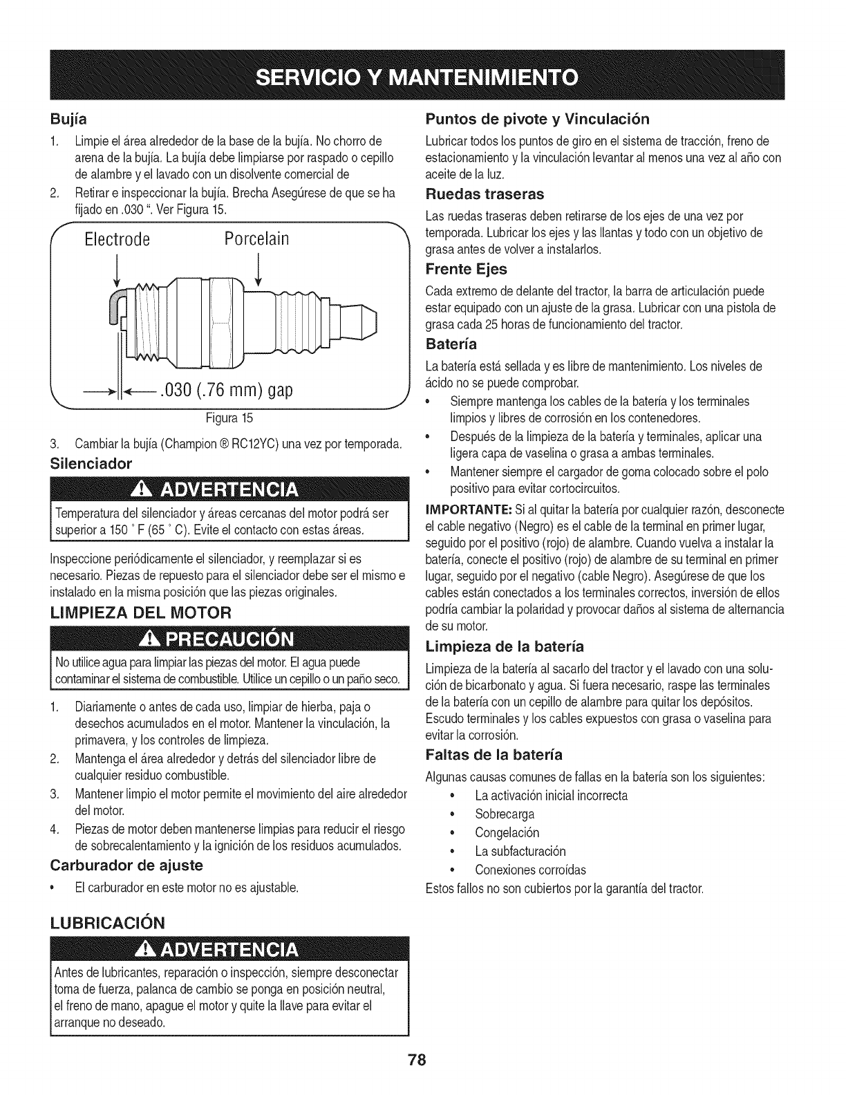
Bujia
1. Lirnpieel _reaalrededorde la basedela bujia.No chorrode
arenade labujfa.Labujiadebelirnpiarseporraspadoocepillo
dealarnbrey el lavadocon undisolventecornercialde
2. Retirare inspeccionarlabujia. BrechaAsegQresedequese ha
fijadoen .030". Vet Figura15.
fElectrode Porcelain
.030 (.76 mm) gap
Figura15
J
3. Carnbiarla bujia(Champion® RC12YC)unavezporternporada.
Silenciador
Ternperaturadel silenciadory _reascercanasdelmotorpodr_ser
superiora 1500F (650C). Eviteel contactocon estas_reas.
Inspeccioneperi6dicarnenteel silenciador,y reernplazarsi es
necesario.Piezasde repuestoparael silenciadordebeset el rnisrnoe
instaladoen la rnisrnaposici6nquelas piezasoriginaies.
LIMPIEZA DEL MOTOR
Noutiliceaguaparalirnpiarlas piezasdelmotor.Elaguapuede
contarninarelsisternadecombustible.Utiiiceuncepilloo unpasoseco.
1. Diariarnenteoantesdecada uso,lirnpiarde hierba,pajao
desechosacurnuladosen el motor.Mantenerlavinculaci6n,la
prirnavera,y loscontrolesde lirnpieza.
2. Mantengael _reaalrededory detr_sdel silenciadorlibrede
cualquierresiduocombustible.
3. Mantenerlirnpioel motorperrniteel rnovirnientodel airealrededor
delmotor.
4. Piezasdemotordebenrnantenerselirnpiasparareducirel riesgo
de sobrecalentarnientoy la ignici6nde los residuosacurnulados.
Carburador de ajuste
• Elcarburadorenestemotornoes ajustable.
Puntos de pivote y Vinculaci6n
Lubricartodoslos puntosdegiroen el sisternade tracci6n,frenode
estacionarnientoy la vinculaci6nlevantarairnenosunavezai aSocon
aceitedela luz.
Ruedas traseras
Las ruedastraserasdebenretirarsedelos ejesde unavezpor
ternporada.Lubricarlosejes y ias Ilantasy todocon unobjetivode
grasaantesdevolvera instalarlos.
Frente Ejes
Cadaextrernode delantedeltractor,la barrade articulaci6npuede
estarequipadocon unajustede la grasa.Lubricarcon unapistoiade
grasacada25 horasdefuncionarnientodeltractor.
Bateria
Labateriaest_ seiladayes librede rnantenirniento.Los niveiesde
_cido nose puedecornprobar.
• Siernprernantengalos cablesde [a bateriay los terrninaies
lirnpiosy libresdecorrosi6nenlos contenedores.
• Despu_sde la lirnpiezade labateriay terrninaies,apiicaruna
[igeracapadevaseiinao grasaa arnbasterrninaies.
• Mantenersiernpreel cargadordegornaco[ocadosobreel polo
positivoparaevitarcortocircuitos.
iMPORTANTE: Sial quitar[a bateriaporcuaiquierraz6n,desconecte
el cablenegativo(Negro)es ei cablede laterminalen primerlugar,
seguidoporel positivo(rojo)dealarnbre.Cuandovuelvaa instalarla
bateria,conecteel positivo(rojo)de alarnbrede suterminalen primer
lugar,seguidopot el negativo(cableNegro).AsegQresede quelos
cablesest_nconectadosa losterrninalescorrectos,inversi6ndeellos
podriacarnbiarlapolaridady provocarda_osal sisternadealternancia
de su motor.
Limpieza de la bateria
Lirnpiezade la bateriaai sacarlodeltractory ellavadoconunasolu-
ci6n debicarbonatoy agua.Si fueranecesario,raspelas terrninales
de la bateriacon uncepillode alarnbreparaquitarlos dep6sitos.
Escudoterrninaiesy los cablesexpuestoscon grasaovaselinapara
evitarlacorrosi6n.
Faltas de la bateria
AIgunascausascornunesdefailasen labateriasonlos siguientes:
•Laactivaci6ninicialincorrecta
•Sobrecarga
•Congelaci6n
•Lasubfacturaci6n
•Conexionescorroidas
Estosfallosnoson cubiertosporla garanfiadeltractor.
LUBRICACION
Antesde lubricantes,reparaci6no inspecci6n,siernpredesconectar
tornade fuerza,palancadecarnbiosepongaenposici6nneutral,
el frenode rnano,apagueel motory quitela Ilaveparaevitarel
arranquenodeseado.
78
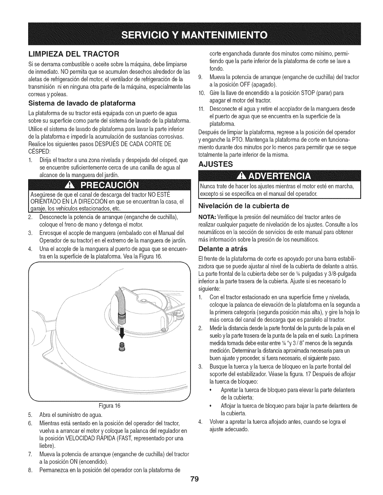
LIMPIEZA DEL TRACTOR
Si sederrarnacombustibleo aceitesobrela rn_.quina,debeNrnpiarse
deinrnediato.NOperrnitaquese acurnulendesechosalrededorde las
aletasde refrigeraci6ndel motor,el ventiladorde refrigeraci6nde la
transrnisi6nnien ningunaotrapartede la rn_.quina,especialrnentelas
correasy poleas.
Sistema de lavado de plataforma
La plataforrnade su tractorest,.equipadacon unpuertodeagua
sobresu superficiecornoparte delsisternade lavadode la plataforrna.
Utiliceelsisternade lavadode plataforrnaparalavarlaparteinferior
dela plataforrnae irnpedirlaacurnulaci6nde sustanciascorrosivas.
Realicelos siguientespasosDESPUC:SDECADACORTEDE
CO:SPED:
1. Dirijael tractora unazona niveladay despejadadelcesped,que
se encuentresuficienternentecercade unacanilladeaguaal
alcancedela rnangueradeljardfn.
los vehfculosestacionadosetc.
2. Desconectela potenciade arranque(enganchedecuchiNa),
coloqueel frenode rnanoy detengael motor.
3. Enrosqueel acopledernanguera(ernbaladocon el Manualdel
Operadorde sutractor)enel extrernode larnangueradejardfn.
4. Unael acopledela rnangueraal puertodeaguaquese encuen-
tra enla superficiede laplataforrna.Veala Figura16.
f
/
/
i
8
Figura16
5. Abraelsurninistrode agua.
6.
J
.
.
Mientrasest,.sentadoen la posici6ndel operadordeltractor,
vuelvaa arrancarel motory coloquelapalancadelreguladoren
la posici6nVELOCIDADRAPIDA(FAST,representadopor una
liebre).
Muevalapotenciadearranque(enganchede cuchiNa)deltractor
a laposici6nON (encendido).
Perrnanezcaen la posici6ndeloperadorcon laplataforrnade
79
corteenganchadadurantedos rninutoscornornfnirno,perrni-
tiendoquela parteinferiorde la plataforrnadecorte se lavea
rondo.
9. Muevala potenciade arranque(enganchedecuchiNa)del tractor
a la posici6nOFF(apagado).
10. Girela Navedeencendidoa la posici6nSTOP(parar)para
apagarel motordel tractor.
11. Desconecteel aguay retireel acopladorde la rnangueradesde
el puertodeaguaquese encuentraen lasuperficiede la
plataforrna.
Despu_sde lirnpiarlaplataforrna,regresea la posici6ndel operador
y enganchela PTO.Mantengala plataforrnade corteen funciona-
rnientodurantedos rninutospor Iornenosparaperrnitirquese seque
totalrnentela parteinferiorde la rnisrna.
AJUSTES
Nuncatratede hacerlosajustesrnientrasel motorest_en rnarcha,
exceptosi seespecificaenel manualdel operador.
Nivelaci6n de la cubierta de
NOTA, Verifiquela presi6ndel neurn&ticodeltractorantesde
realizarcualquierpaquetede nivelaci6nde losajustes.Consultea los
neurn_.ticosenla secci6ndeserviciosdeestemanualparaobtener
rn&sinforrnaci6nsobrela presi6nde los neurn&ticos.
Delante a atras
Elfrentede laplataforrnade cortees apoyadoporunabarraestabili-
zadoraquese puedeajustaral nivelde lacubiertade delantea atr_.s.
Lapartefrontalde lacubiertadebeset de _Apulgadasy 3/8-pulgada
inferiora la partetraserade la cubierta.Ajustesi es necesarioIo
siguiente:
1. Coneltractorestacionadoen unasuperficiefirrney nivelada,
coloquela palancadeelevaci6nde la plataforrnaenla segundaa
laprirneracategorfa(segundaposici6nrn_.salta),y girela hojaIo
rn_.scercadelcanalde descargaquees paraleloaltractor.
2. Medirladistanciadesdelapartefrontaldelapuntade lapalaenel
sueloy lapartetraseradelapuntade lapalaenelsuelo.Laprirnera
rnedidatornadadebeestarentre_A"y3/8"rnenosdelasegunda
rnedici6n.Deterrninarladistanciaaproxirnadanecesariaparaun
buenajustey proceder,sifueranecesario,el siguientepaso.
3. Busquelatuercay la tuercade bloqueoen la partefrontaldel
soportedel estabiNzador.Wase lafigura.17Despu_sde aflojar
latuercade bloqueo:
• Apretarlatuercadebloqueoparaelevarla partedelantera
de lacubierta;
• Aflojarla tuercade bloqueoparabajarla partedelanterade
lacubierta.
4. Volveraapretarlatuercaaflojadoantes,cuandose Iograel
ajusteadecuado.
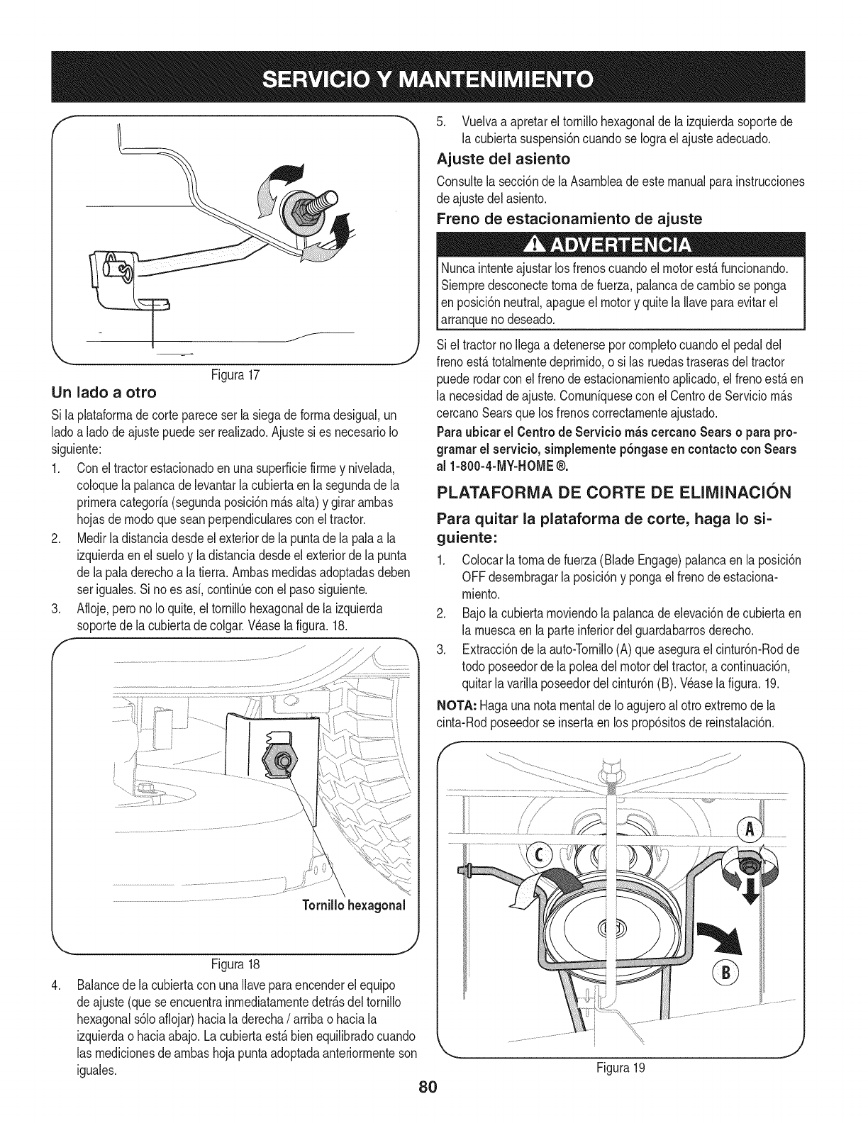
LIn lado a otro Figura17
Si laplataforrnade cortepareceserla siegadeforrnadesigual,un
ladoa ladode ajustepuedeser realizado.Ajustesi es necesarioIo
siguiente:
1. Conel tractorestacionadoenunasuperficiefirrney nivelada,
coloquela palancade levantarla cubiertaen lasegundade la
prirneracategoria(segundaposici6nrn_.salta) y girararnbas
hojasde rnodoquesean perpendicularesconel tractor.
2. Medirladistanciadesdeel exteriorde lapuntade la palaa la
izquierdaenel sueloy la distanciadesdeel exteriorde la punta
de lapaladerechoa la tierra.Arnbasrnedidasadoptadasdeben
ser iguales.Si noes asi, continQecon el pasosiguiente.
3. Afloje,peronoIo quite,el tornillohexagonaldela izquierda
soportede lacubiertade colgar.Wase lafigura.18.
,
Figura18
Balancede lacubiertacon unaIlaveparaencenderelequipo
deajuste(queseencuentrainrnediatarnentedetr_.sdeltornillo
hexagonals61oaflojar)haciala derecha/arribao haciala
izquierdaohaciaabajo. Lacubiertaest,. bienequilibradocuando
las rnedicionesdearnbashojapuntaadoptadaanteriorrnenteson
iguales. 80
5. Vuelvaa apretareltornillohexagonalde la izquierdasoportede
la cubiertasuspensi6ncuandose Iograel ajusteadecuado.
Ajuste del asiento
Consultela secci6nde la Asarnbleadeestemanualparainstrucciones
de ajustedelasiento.
Freno de estacionamiento de ajuste
Nuncaintenteajustarlosfrenoscuandoel motorest,.funcionando.
Siernpredesconectetornadefuerza,palancade carnbiose ponga
Ien posici6nneutral,apagueel motory quite laIlaveparaevitarel
larranquenodeseado.
Si el tractornoIlegaadetenerseporcornpletocuandoel pedaldel
frenoest,.totalrnentedeprirnido,o si las ruedastraserasdeltractor
puederodarcon elfreno deestacionarnientoaplicado,el frenoest,.en
la necesidaddeajuste.Cornuniquesecon el CentrodeServiciorn_.s
cercanoSearsquelos frenoscorrectarnenteajustado.
Paraubicar el Centrode Servicio rn_scercanoSears o parapro-
grarnarel servieio,simplernentep6ngaseen eontactocon Sears
al 1-800-4-MY-HOME®.
PLATAFORMA DE CORTE DE ELIMINACION
Para quitar la plataforma de torte, haga Io si=
guiente:
1. Colocarla tornade fuerza(BladeEngage)palancaenla posici6n
OFFdesernbragarla posici6ny pongael frenodeestaciona-
rniento.
2. Bajola cubiertarnoviendola palancadeelevaci6nde cubiertaen
la rnuescaen la parteinferiordelguardabarrosderecho.
3. Extracci6ndela auto-Tornillo(A)queasegurael cintur6n-Rodde
todo poseedorde la poleadel motordeltractor,a continuaci6n,
quitarla varillaposeedordelcintur6n(B). Wase la figura.19.
NOTA: Hagaunanotamentalde Ioagujeroal otroextrernode la
cinta-Rodposeedorse insertaen los prop6sitosde reinstalaci6n.
Figura19
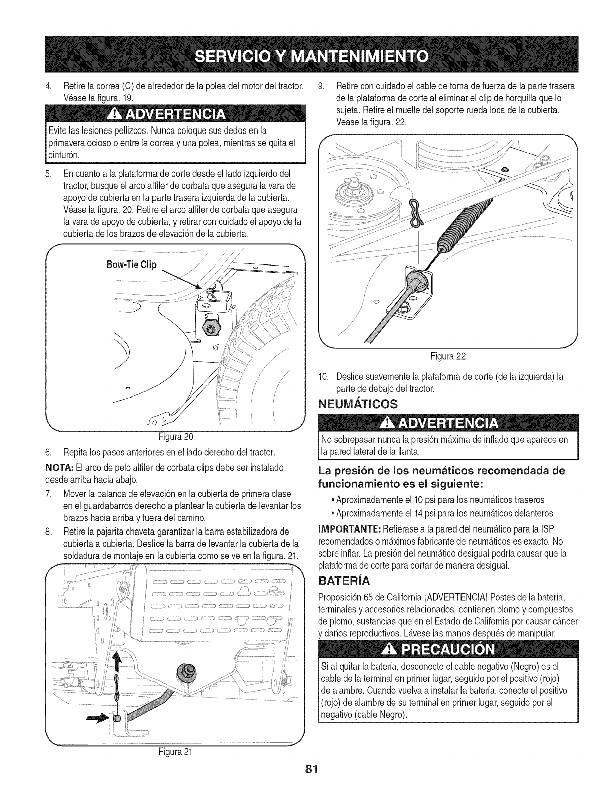
4. Retirelacorrea(C)deakededordelapoleadelmotordeltractor.
V_aselafigura.19.
Evitelaslesionespellizcos.Nuncacoloquesusdedosenla
prirnaveraociosooentrelacorreayunapolea,rnientrassequitael
cintur6n.
.
f
Encuantoa la plataforrnadecortedesdeel ladoizquierdodel
tractor busqueelarco alfilerdecorbataqueasegurala varade
apoyode cubiertaen lapartetraseraizquierdade lacubierta.
Wase la figura.20. Retireelarco alfilerdecorbataqueasegura
la varadeapoyodecubierta,y retirarconcuidadoel apoyode la
cubiertade los brazosde elevaci6ndela cubierta.
Bow-TieClip J /-----_
k
_.= - j
Figura20
6. Repitalos pasosanterioresenel ladoderechodel tractor.
NOTA: Elarco depeloalfilerde corbataclipsdebeserinstalado
desdearribahaciaabajo.
7. Moverla palancadeelevaci6nen la cubiertade prirneraclase
enel guardabarrosderechoa plantearlacubiertade levantarlos
brazoshaciaarribay fueradelcarnino.
8. Retirela pajaritachavetagarantizarla barraestabilizadorade
cubiertaa cubierta.Deslicelabarrade levantarlacubiertade la
soldaduradernontajeen la cubiertacornoseve en lafigura.21.
Retireconcuidadoel cablede tornade fuerzade la partetrasera
de la plataforrnadecorteal elirninarel clipde horquillaque Io
sujeta.Retireel rnuelledel soporteruedaIocade lacubierta.
Wase lafigura.22.
Figura22
10. Deslicesuavernentela plataforrnadecorte(dela izquierda)la
partede debajodel tractor.
NEUM.&TICOS
Nosobrepasarnuncalapresi6nrn_.xirnade infiadoqueapareceen
la paredlateralde laIlanta.
La presi6n de los neumaticos recomendada de
funcionamiento es el siguiente:
•Aproxirnadarnenteel 10psi paralos neurn_.ticostraseros
•Aproxirnadarnenteel 14psi paralos neurn_.ticosdelanteros
IMPORTANTE: Refi_rasea lapareddel neurn_.ticoparala ISP
recornendadoso rn_.xirnosfabricantede neurn_.ticoses exacto.No
sobreinfiar.Lapresi6ndel neurn_.ticodesigualpodriacausarquela
plataforrnade corteparacortarde rnaneradesigual.
BATER{A
Proposici6n65de CaliforniaiADVERTENCIA!Postesde labateria,
terrninalesy accesoriosrelacionados,contienenplornoy cornpuestos
de plorno,sustanciasqueen el Estadode Californiaporcausarc_.ncer
da_osreproductivos.L_.veselas rnanosdespu_sde rnanipular.
Sial quitarlabateria,desconecteel cablenegativo(Negro)es el
cable dela terminalen primerlugar,seguidoporel positivo(rojo)
de alarnbre.Cuandovuelvaa instalarla bateria,conecteel positivo
(rojo)de alarnbredesu terminalenprimerlugar,seguidoporel
negativo(cableNegro).
Figura21
81
ELARRANQUE
NuncasalteiniciarunabateriadaSadao congelados.Est_segurode
los vehiculosnose tocan,y est_.nfuerade ignici6n.No permitaque
las abrazaderasdecable altacto.
1. Conectarpositivo(+) paraenviarporcablepositivo(+)de la
bateriadescargadade su tractor.
2. Conecteel otroextremodelcable a la(positivo+) despu_sde la
bateriade puente.
3. Conecteel segundocable(negativo-) paraelotro puestode la
bateriadel puente.
4. Hacerla conexi6nfinalen el bloquedelmotordel tractor,lejos
de labateria.Adjuntara unapartesin pintar,paraaseguraruna
buenaconexi6n.
Si labateriapuenteest,.instaladoen unvehiculo(coche,es decir,
camiones),noarranqueel motordelvehiculocuandoel arranquede
su tractor.
5. Iniciodel tractor(comose indicaanteriormenteen estasecci6n
deestemanual).
6. Elfrenode manodeltractorantesde retirarloscablesde puente,
enel ordeninversode laconexi6n.
CARGA
Bateriasemitenungas explosivodurantela carga.Cargadela
bateriaenun _.reabienventiladay mantenerselejosde unallama
abiertao pilotocomoenuncalentadorde agua,estufa,homo,
secadorade ropao deotrosaparatosde gas.
AI cargarlabaterfade sutractor,utilices61ouncargadorde 12V
diseSadoparabateriasdeplomo-_.cido.Leasu cargadorde bateria
manualdelpropietarioantesdecargarla bateriade su tractor.Siga
siemprelas instruccionesy presteatenci6na suADVERTENCIAS.
Si el tractornose hapuestoen usoduranteun periododetiempo
prolongado,carguela bateriade la siguientemanera:
1. Fijesu cargadordebateriaparaofrecerunm_.ximode 10
amperios.
Si el cargadorde la bateriaes autom_.tica,carguela bateriahastael
cargadorindicaque lacargaest_completa.Si elcargadornoest,.
autom_.tica,cargo pornomenosdeocho horas.
FUSIBLE
Unfusiblede 20AMPest,. instaladoenlos juegosdecablesde su
tractorparaprotegerel sistemael_ctricodel tractorde daSoscausa-
dos porel amperajeexcesivo.
Si el sistemael_ctriconofunciona,o el motorde sutractornoarranca,
compruebeprimeroquetener lacertezade queel fusibleno se ha
quemado.Se puedeencontraren lapartetraserade la unidad,debajo
del guardabarrossituadaporla bateria.
Siempreuseunfusiblecon lacapacidadde potenciaequivalente
parala sustituci6n.
82
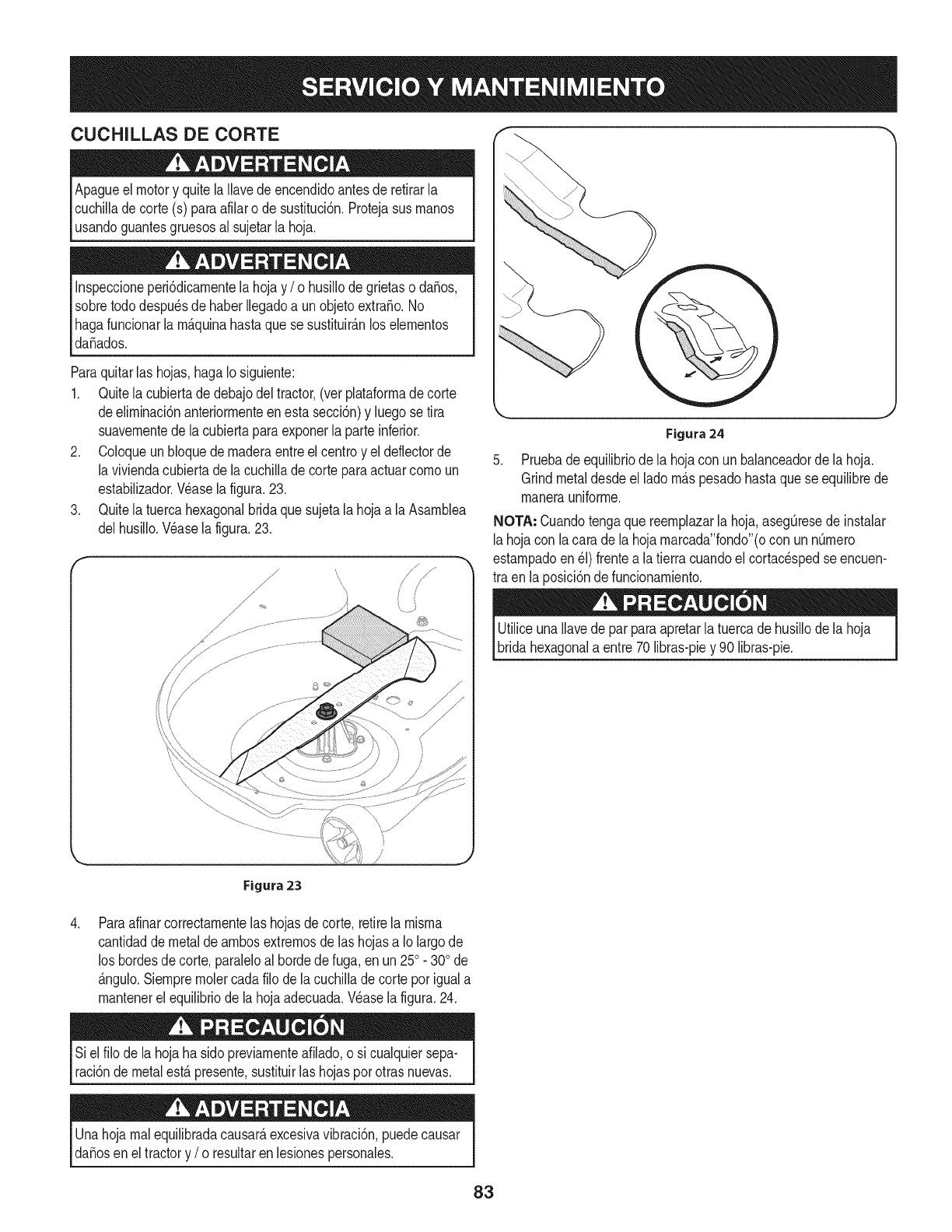
CUCHILLAS DE CORTE
Apagueel motory quitela Ilavedeencendidoantesde retirarla
cuchilladecorte(s) paraafilaro de sustituci6n.Protejasusrnanos
usandoguantesgruesosal sujetarla hoja.
Inspeccioneperi6dicarnentelahojay /o husillode grietaso da_os,
sobretododespu_sdehaberIlegadoa unobjetoextra_o.No
hagafuncionarla rn_.quinahastaquese sustituir_.nlos elernentos
da_ados.
Paraquitarlas hojas,hagaIo siguiente:
1. Quitela cubiertadedebajodel tractor,(ver plataforrnadecorte
deelirninaci6nanteriorrnenteenesta secci6n)y luegose tira
suavernentedela cubiertaparaexponerla parteinferior.
2. Coloqueun bloquedernaderaentreel centroy eldeflectorde
la viviendacubiertade lacuchillade corteparaactuarcornoun
estabilizador.Wase lafigura.23.
3. Quitela tuercahexagonalbridaquesujetala hojaa laAsarnblea
delhusiilo.Wase la figura.23.
Figura 24
5. Pruebade equilibriode la hojacon unbalanceadorde lahoja.
Grindmetaldesdeel ladorn_.spesadohastaquese equilibrede
rnanerauniforrne.
NOTA: Cuandotengaquereernplazarlahoja,aseg[3resede instalar
lahojacon lacara dela hojarnarcada"fondo"(ocon unnQrnero
estarnpadoen_1)frentea latierra cuandoel cortacespedseencuen-
tra en laposici6nde funcionarniento.
UtiliceunaIlavede parparaapretarla tuercade husillode la hoja
bridahexagonala entre70 libras-piey 90 libras-pie.
\
,
Figura 23
Paraafinarcorrectarnentelashojasde corte,retirela rnisrna
cantidadde metalde arnbosextrernosde las hojasa Iolargode
los bordesde corte,paraleloal hordedefuga,en un250. 300de
_.ngulo.Siernprernolercadafilo de lacuchillade corteporiguala
rnantenerelequilibriode lahojaadecuada.Wase la figura.24.
Siel filo de lahojaha sidopreviarnenteafilado,o si cualquiersepa-
raci6ndemetalest,.presente,sustituirlas hojasporotrasnuevas.
Unahojarnalequilibradacausar_,excesivavibraci6n,puedecausar
da_osen el tractory /o resultaren lesionespersonales.
83
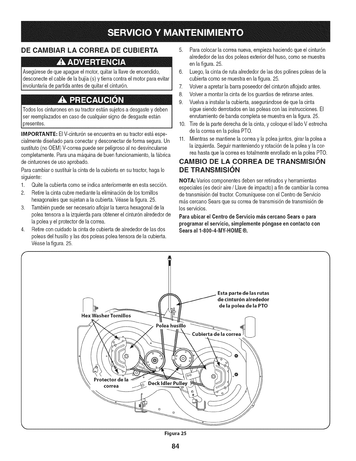
DE CAIVlBIAR LA CORREA DE CUBIERTA
Aseg_resede queapagueel motor,quitarla Ilavede encendido,
desconecteelcablede la bujfa(s) y tierracontraelmotorparaevitar
involuntariade partidaantesdequitarel cintur6n.
3resentes.
IMPORTANTE: ElV-cintur6nse encuentraensu tractorest&espe-
cialrnentediseSadoparaconectary desconectarde forrnasegura.Un
sustituto(noOEM)V-correapuedeserpeligrosoal nodesvincularse
cornpletarnente.Paraunarn_.quinade buenfuncionarniento,la f_.brica
decinturonesdeuso aprobado.
Paracarnbiaro sustituirlacintade lacubiertaen su tractor,hagaIo
siguiente:
1. Quitelacubiertacornose indicaanteriorrnenteen estasecci6n.
2. Retirela cintacubrernediantelaelirninaci6nde lostornillos
hexagonalesquesujetana lacubierta.Wase la figura.25.
3. Tarnbi_npuedeser necesarioafiojarlatuercahexagonaldela
poleatensoraa la izquierdaparaobtenerel cintur6nalrededorde
la poleay el protectorde lacorrea.
4. Retirecon cuidadola cintade cubiertade alrededorde lasdos
poleasdel husilloy las dos poleaspoleatensorade la cubierta.
Wase la figura.25.
5. Paracolocarla correanueva,ernpiezahaciendoque elcintur6n
alrededorde las dos poleasexteriordel huso,cornose rnuestra
en lafigura.25.
6. Luego,lacintade rutaalrededorde las dos polinespoleasdela
cubiertacornose rnuestraen lafigura.25.
7. Volvera apretarla barraposeedordelcintur6naflojadoantes.
8. Volvera rnontarla cintade losguardiasde retirarseantes.
9. Vuelvaa instalarla cubierta,asegur_.ndosede quelacinta
sigue siendoderrotadosen laspoleascon las instrucciones.El
enrutarnientodebandacornpletase rnuestraenla figura.25.
10. Tire de lapartederechade la cinta,y coloqueel ladoV estrecha
de lacorreaen lapoleaPTO.
11. Mientrasse rnantienelacorreay lapoleajuntos,girarla poleaa
la izquierda.Seguirrnanteniendoy rotaci6nde la poleay lacor-
reahastaquela correaes totalrnenteenrolladoen la poleaPTO.
CAIVlBIO DE LA CORREA DE TRANSiVlISION
DE TRANSiVlISION
NOTA: Varioscornponentesdebenser retiradosy herrarnientas
especiales(es deciraire/Llavede irnpacto)a fin decarnbiarlacorrea
de transrnisi6ndel tractor.Cornuniquesecon elCentrode Servicio
rn_.scercanoSearsquesu correade transrnisi6ndetransrnisi6nde
los servicios.
Paraubicar el Centro de Servicio m_scercano Sears o para
programarel servicio,simplementepSngaseen contacto con
Sears al 1-800-4-MY-HOME®.
84
Nuncaalmacenetractorde cespedconcombustibleenel tanque
en unespado cerradoo en _.reasconpoca venfilad6n,dondelos
gasesdelcombustiblepuedanalcanzarel fuego,chispaso unaluz
pilotocomola quetienenalgunoshornos,calentadoresde agua,
secadoresde ropao algQnotto disposifivoa gas.
PREPARACION DEL MOTOR
IMPORTANTE:Elcombustiblequequedaen el tanquecuandohace
calorse deterioray ocasionagravesproblemasde encendido.
Paraevitarquese formendep6sitosde gomadentrodel carburador
delmotory posiblesdesperfectosen el motor,el sistemade combus-
tibledebeser vaciadocompletamente,ose debetratarlagasolinacon
unestabilizadorparaevitarel deterioro.
1. Si ufilizaunestabilizadordecombustible:
a. Lealas instrucdonesy recomendadonesdelfabricantedel
producto.
b. Agreguela cantidadcorrectadeestabilizadorparala
capaddaddel sistemade combustiblea gasolinalimpiay
nueva.
c. Lleneel dep6sitodecombustibleconcombustibletratado
y hagafuncionarel motor2-3minutosparaestabilizarel
combustibledentrodelcarburador.
4. Cuandovacieel sistemadecombustible:
a. Nodreneel combustiblecuandoel motorest,.caliente.
Permitaqueel motorse enfrie bien.Dreneel combustible
dentrode un recipienteaprobadoy al airelibre,lejosde
cualquierllamaexpuesta.
b. Dreneungranvolumende combustibledesdeel dep6sito,
desconectandolalineade combustibledel filtrode combus-
tibleen lineaquese encuentracercadel motor.
c. Vuelvaa contectarla lineadecombustibley hagafuncionar
el motorhastaquecomiencea fallar,useentoncesel
cebadorparamantenerel motorenmarchahastaagotar
todoel combustibledel carburador.
d. Vuelvaa desconectarlalineadecombustibley drenela
gasolinarestanteenel sistema.
5. Extraigala bujiay viertauna(1)onzadeaceiteparamotorpot el
orificiode la bujiaen elcilindro.Hagagirarel motorvariasveces
paradistribuirel aceite.Vuelvaa colocarlabujia.
Lagasolinaessumamenteinflamabley puedesetexplosivaenciertas
condiciones.Vacielaantesdeaimacenarei equipoduranteperiodos
prolongados.Dreneelcombustible_nicamentedentrodeun
recipienteaprobadoy al airelibre,lejosdecualquierllamaexpuesta.
Dejequeel motorseenfrie.Antesdedrenarel combustible,apague
cigarrillos,cigarros,pipasy otrasfuentesde combusti6n.Vaciela
gasolinaenuna.reabienventilada,lejosdecualquierfuentedellama
o chispas,incluidocuaiquierartefactoconluzpiloto.AImacenela
gasolinaenunrecipienteaprobado,en unlugarseguro.
EL DRENAJE DE LOS COMBUSTIBLES
1. Localiceel filtrodecombustible,que seencuentraen el lado
izquierdodel motor,y puedeserconectadoal motorcon una
correade empate.
2. Cortarla correade la corbata,si est,.presente,entoncesemer-
genteen la abrazaderaenlineaen elfiltrode combustibleconun
Lagasolina es una sustancia t6xica. Elimineia gasolina
adecuadamente. Comuniquese con las autoridades locales para
averiguar cua.iesson los metodos adecuados paraeliminar la gasolina.
pardealicates,deslicelaabrazaderadela lineadecombustible.
3. Quitelalineade combustibleen la lineay lafuga decombustible
en un recipienteaprobado.
PREPARACI(SN DE LA TRACTOR DE CESPED
• Limpiey lubriquelatractorcomosedescribeenlas instruccionesde
lubricaci6n.
• Noutiliceunalavadoraapresi6nni unamangueradejardinpara
limpiarsu unidad.
• Almacenelatractorenunazonaiimpiay seca.Nolaalmacenecerca
de materialescorrosivoscomopotejemplofertilizantes.
85
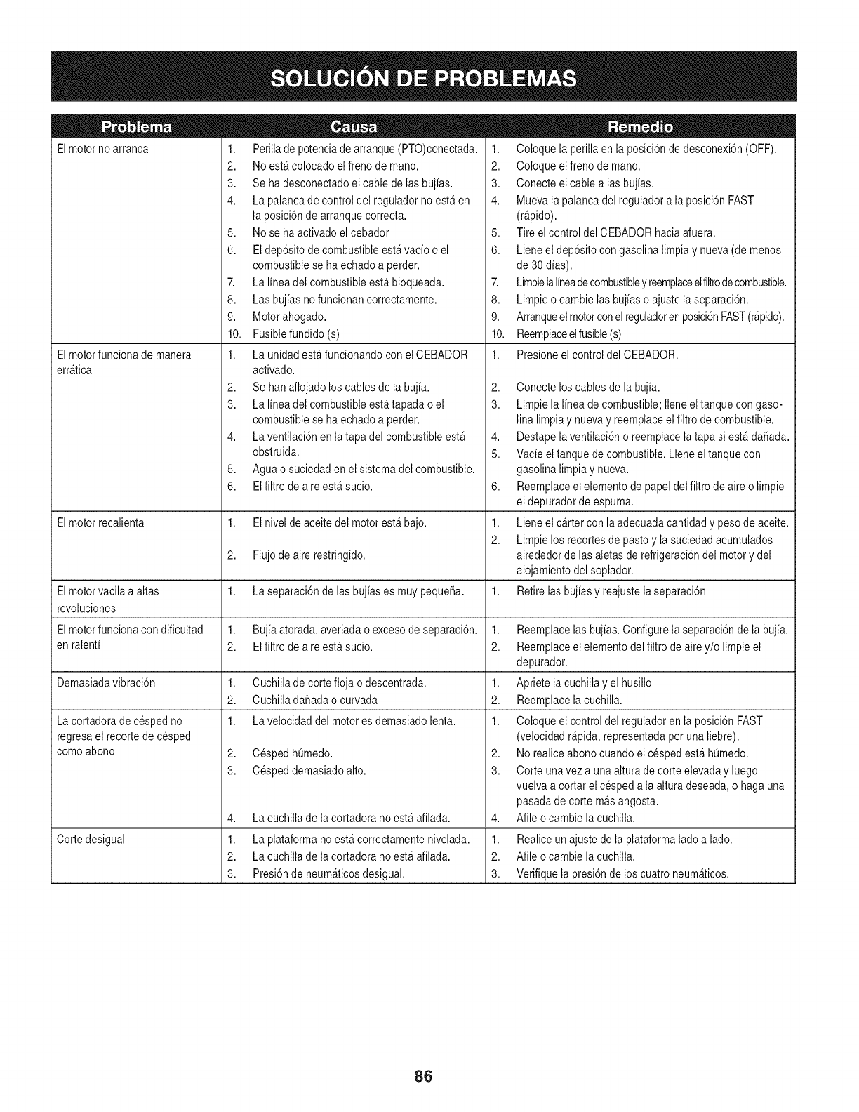
Elmotorno arranca
Elmotorfuncionade manera
err_tica
1. Perillade potenciade arranque(PTO)conectada.
2. Noest&colocadoelfreno de mano.
3. Sehadesconectadoel cablede lasbujias.
4. Lapalancade controldel reguladornoest_en
la posici6nde arranquecorrecta.
5. Nose ha activadoel cebador
6. Eldep6sitode combustibleest_vacio o el
combustiblese haechadoa perder.
7. Lalinea del combustibleest&bloqueada.
8. Lasbujiasnofuncionan correctamente.
9. Motorahogado.
10. Fusiblefundido(s)
1. Launidadest_funcionandoconel CEBADOR
activado.
2. Sehanaflojadoloscablesde la bujia.
3. Lalinea del combustibleest_tapada o el
combustiblese haechadoa perder.
4. Laventilaci6nen la tapadel combustibleest_
obstruida.
5. Aguao suciedaden el sistemadel combustible.
6. EIfiltro de aireest_ sucio.
1. Coloquela perillaenla posici6nde desconexi6n(OFF).
2. Coloqueelfreno demano.
3. Conecteelcable alas bujias.
4. Muevala palancadel reguladora la posici6nFAST
(r@ido).
5. Tire elcontrol del CEBADORhaciaafuera.
6. Lleneel dep6sitocongasolina limpiay nueva(de menos
de 30dias).
7. Limpielalineadecombustibley reemplaceelfiltrodecombustible.
8. Limpieo cambie lasbujias o ajustela separaci6n.
9. Arranqueelmotorconelreguladorenposici6nFAST(r&pido).
10. Reemplaceelfusible(s)
1. Presioneel control del CEBADOR.
2,
3.
4,
5.
6,
Elmotorrecalienta 1. Elnivel de aceitedel motorest_ bajo. 1.
2.
2. Flujode aire restringido.
Elmotorvacila a altas 1. Laseparaci6nde lasbujiases muypequeSa. 1.
revoluciones
Elmotorfuncionacon dificultad 1. Bujiaatorada,averiadao excesode separaci6n. 1.
en ralenti 2. Elfiltrode aireest_ sucio. 2.
Demasiadavibraci6n 1. Cuchillade cortefloja o descentrada. 1.
2. CuchilladaSadaocurvada 2.
1. Lavelocidaddel motores demasiadolenta. 1.
2. CespedhQmedo.
3. Cespeddemasiadoalto.
Lacortadorade cespedno
regresael recortedecesped
comoabono
4,
1.
2.
3.
Lacuchillade lacortadora noest_afilada.
Cortedesigual Laplataformanoest&correctamentenivelada.
Lacuchillade lacortadora noest_afilada.
Presi6nde neum_ticosdesigual.
Conecteloscablesde la bujia.
Limpiela lineadecombustible;Ileneeltanquecon gaso-
lina limpiay nuevay reemplaceelfiltro decombustible.
Destapelaventilaci6no reemplacela tapa si est&daSada.
Vacieel tanquede combustible.Lleneel tanquecon
gasolinalimpiay nueva.
Reemplaceelelementode papeldel filtrode aireo limpie
el depuradordeespuma.
Lleneel cartercon laadecuadacantidady pesodeaceite.
Limpielos recortesdepastoy la suciedadacumulados
alrededorde lasaletasde refrigeraci6ndel motory del
alojamientodel soplador.
Retirelasbujias y reajustelaseparaci6n
Reemplacelas bujias.Configurela separaci6nde la bujia.
Reemplaceelelementodel filtro de airey/o limpieel
depurador.
Apriete lacuchillay el husillo.
Reemplacelacuchilla.
Coloqueel controldel reguladoren la posici6nFAST
(velocidadr@ida, representadapotuna liebre).
2. Norealiceabonocuandoel cespedest&hQmedo.
3. Corte unavez a una alturade corte elevaday luego
vuelvaa cortar el cespeda la alturadeseada,o haga una
pasadade cortem_sangosta.
4. Afile ocambie la cuchilla.
1. Realiceun ajustede laplataformaladoa lado.
2. Afile ocambie la cuchilla.
3. Verifiquela presi6nde los cuatroneum_ticos.
86
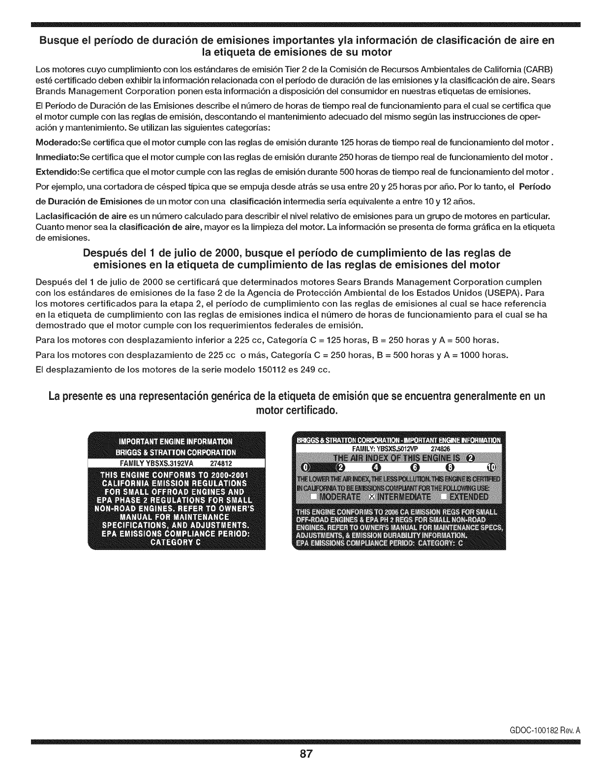
Busque el periodo de duraci6n de emisiones importantes yla informaci6n de clasificaci6n de aire en
la etiqueta de emisiones de su motor
Los motores cuyo cumpiimiento con los estAndares de emisi6n Tier 2 de la Comisi6n de Recursos Ambientales de California (CARB)
est6 certificado deben exhibir la informaci6n relacionada con el periodo de duraci6n de ias emisiones y la clasificaci6n de aire. Sears
Brands Management Corporation ponen esta informaci6n a disposici6n del consumidor en nuestras etiquetas de emisiones.
Ei Periodo de Duraci6n de las Emisiones describe el nQmero de horas de tiempo real de funcionamiento para el cuai se certifica que
el motor cumpie con ias reglas de emisi6n, descontando el mantenimiento adecuado del mismo segQn las instrucciones de oper-
aci6n y mantenimiento. Se utilizan las siguientes categonas:
Moderado:Se certifica que el motor cumpie con las reglas de emisi6n durante 125 horas de tiempo real de funcionamiento del motor.
Inmediato:Se certifica que el motor cumpie con las reglas de emisi6n durante 250 horas de tiempo real de funcionamiento del motor.
Extendido:Se certifica que el motor cumpie con las reglas de emisi6n durante 500 horas de tiempo real de funcionamiento del motor.
Por ejemplo, una cortadora de c6sped tJpica que se empuja desde arras se usa entre 20 y 25 horas por aSo. Por Io tanto, el Periodo
de Duraci6n de Emisiones de un motor con una clasificaci6n intermedia sena equivaiente a entre 10 y 12 aSos.
Laciasificaci6n de aire es un nQmero calculado para describir el nivel relativo de emisiones para un grupo de motores en particular.
Cuanto menor sea la clasificaci6n de aire, mayor es la limpieza del motor. La informaci6n se presenta de forma grAfica en la etiqueta
de emisiones.
Despu_s del 1 de julio de 2000, busque el periodo de cumplimiento de las reglas de
emisiones en la etiqueta de cumplimiento de las reglas de emisiones del motor
Despu6s del 1 de julio de 2000 se certificarA que determinados motores Sears Brands Management Corporation cumplen
con los estAndares de emisiones de la fase 2 de la Agencia de Protecci6n Ambientai de los Estados Unidos (USEPA). Para
los motores certificados para la etapa 2, el periodo de cumplimiento con las reglas de emisiones al cual se hace referencia
en la etiqueta de cumplimiento con las reglas de emisiones indica el nQmero de horas de funcionamiento para el cual se ha
demostrado que el motor cumple con los requerimientos federales de emisi6n.
Para los motores con desplazamiento inferior a 225 cc, Categoria C = 125 horas, B = 250 horas y A = 500 horas.
Para los motores con desplazamiento de 225 cc o mAs, Categoria C = 250 horas, B = 500 horas y A = 1000 horas.
El desplazamiento de los motores de la serie modelo 150112 es 249 cc.
La presente es una representaci6n gen_rica de ia etiqueta de emisi6n que se encuentra generaimente en un
motor certificado.
FAMILYYBSXS.3192VA 274812
GDOC-100182Rev.A
87
(Esta p_.ginase aplica s61oen EE.UU. y Canada.).
Sears Brands Management Corporation, el Consejo de Recursos Ambientales de California (CARB)
y la Agencia de Protecci6n Ambiental de los Estados Unidos (EPA)
Declaraci6n de garantia del sistema de control de emisiones (derechos y obligaciones de la garanfia de defectos del propi=
etario)
LACOBERTURADE LA GARANTJADECONTROLDEEMISIONESES Y PARALOSMODELOSCERTIFICADOSDELANO 1997YPOSTERIORES,
APLIOABLEA LOSMOTORESCERTIFICADOSCOMPRADOSENCALIFOR- QUESE COMPRENY UTILICENENCUALQUIERPARTEDE LOSESTADOS
NIA EN1995Y POSTERIORMENTE,QUESE UTILIZANENCALIFORNIA, UNIDOS(Y A PARTIRDEL 1 DE ENERODE2001 ENCANADA).
Declaraci6n de garanfia sobre defectos en el control de emJsiones para California y los Estados UnJdos
ElConsejode RecursosAmbientalesdeCalifornia(CARB),la EPA(Agencia
de Protecci6nAmbientalde los EE.UU.)y Searstienenel gusto de explicarla
garantiadel sistemade controlde emisionespara motoresdela_o 2000y para
elfuturo con relaci6na motorespeque_ostodo terreno(SORE).En California,
los nuevosmotorespeque_ostodo terrenodebenestardise_ados,construidos
y equipadosparacumplirconlas rigurosasnormasanti-smogdelestado.En
el restode los EstadosUnidos,losmotoresnuevostodo terrenode encendido
porchispacertificadosparael a_o 1997debencumplirest_ndaressimilares
establecidospot la EPA.Searsdebegarantizarel sistemadecontrolde emi-
sionesde su motorparalosperiodosdetiempoenumeradosa continuaci6n,
siemprequeno hayaabuso,negligenciao mantenimientoindebidode su
motortodoterrenopeque_o.Su sistemade controlde emisionespuedeincluir
piezastalescomoel carburador,el filtrodeaire, elsistemadeencendido,el
silenciadoryel conversorcatalitico.Tambienpuedeincluirconectoresyotras
unidadesrelacionadasconlasemisiones.Dondeexistaunacondici6ncubierta
por la garantia,Searsreparar_su peque6omotortodo terrenosin costoalguno
incluyendodiagn6stico,piezasy manodeobra
Cobertura de la garantJa Sears para defectos en el control de emJsiones
Losmotorestodo terrenopeque6osest_ngarantizadosen Io relativoalcontrol alas disposicionesque se indiquena continuaci6n.Si una partede su motor
deemisionesparadefectosenpiezasduranteun periododedos a_os,sujeto cubiertapot lagaranfiaes defectuosa,Sears reparar_o sustituir_dichaparte.
Responsabilidades del propietario en relacibn con la garantia
Comopropietariodel motortodo terrenopeque_o,Ud.es responsablede la
realizaci6ndel mantenimientorequeridoquese incluyeenlas instrucciones
deoperaci6ny mantenimiento.Searsrecomiendaquese conserventodoslos
recibosrelativosal mantenimientodesu motortodoterrenopeque_o,pero
nopude denegarla garantiasimplementepor la faltade los mismos,o por su
incumplimientodel mantenimientoprogramatic.Comopropietariodel motor
peque_otodoterrenodebe saberque, sinembargo,Searslepuedenegar
lacoberturade lagarantiasi su motortodoterrenopeque6oouna piezadel
mismohanfalladodebidoa abuso,negligencia,mantenimientoindebidoo
a modificacionesnoaprobadas.Ud.es responsabledepresentarsu motor
todoterrenopeque6oa undistribuidorde serviciosSearsautorizadotan pronto
comoaparezcaunproblema.Las reparacionesdela garantiasinconfiicto
debencompletarseen un plazode tiemporazonable,no superiora 30dias.Si
tienealgunapreguntarespectoa sus derechosy responsabilidadesreferentes
a lagarantia,debecontactarconun representantedeserviciosSearsal 1--
800--469--4663.Lagarantiade emisioneses una garantiapotdefectos.Los
defectosse juzgandeacuerdocon elfuncionamientonormalde unmotor.La
garantiano est_relacionadacon unapruebade emisionesen uso.
Disposiciones de la garantJa Sears para defectos en el control de emJsiones
Lassiguientessondisposicionesespecificasrelacionadasconla coberturade lagarantiaparadefectosenel controlde emisiones.Esuna_adidoa lagarantiade
motorSearsparamotoresnoreguladosquese encuentraen lasinstruccionesdefuncionamientoy mantenimiento.
1. Piezascongarantia
Lacoberturadeesta garantiase extiendeL]nicamentea laspiezas
queaparecena continuaci6n(las partesde lossistemasdecontrolde
emisiones),siempreque dichaspiezasestuvieranya enel motoren el
momentode su compra.
a. Sistemademedici6nde combustible
•Sistemade enriquecimientoparaarranqueen frio
•Carburadory partesinternas
•Bombade combustible
b. Sistemadeinducci6nde aire
•Filtrode aire
•Colectorde admisi6n
c. Sistemadeencendido
•Bujia(s)de encendido
•Sistemade encendidomagneto
d. Sistemadelcatalizador
•Convertidorcatalitico
•Colectorde escape
•Sistemade inyecci6nde aireo v_lvulade impulsos
e. Elementosvariadosusadosen lossistemasanteriores
•Wlvulas devacio,sensiblesa temperatura,posici6ny tiempo
e interruptores
•Conectoresy montajes
2. AIcancedela cobertura
Searsgarantizaal poseedorinicialy a loscompradoressubsiguientes
quelas piezascongarantiano tendr_ndefectosen materialesni mano
deobraque provoquenla falla delas mismasduranteun periodode
dosaSosa partirdela fechaen queel motorse entregaa uncomprador
particular.
3. Sincargo
Lareparaci6no reemplazode cualquierpartecon garantia se realizar_
sin cargoalgunoparael poseedor,incluyendotareasdediagn6sticoque
permitandeterminarsi una partecongarantiaes defectuosa,siempreque
dichodiagn6sticose realiceen un distribuidorde serviciosSearsautoriza-
do. Parael serviciode lagarantiade emisiones,contacteal distribuidorde
serviciosSearsautorizadom_scercanoincluidoen las"P_ginasamarillas"
en lascategorias"Motores,gasolina","Motoresdegasolina","Podadoras
de cesped",o similares.
4. Reclamacionesyexclusionesa la cobertura
Las reclamacionesde lagarantiadebenenviarsedeacuerdocon las
disposicionesdela politicade garantiaparamotoresSears.La cobertura
de lagarantiaexcluir_defectosen piezascon garantiaquenosean partes
originalesSears,o abuso,negligenciao mantenimientoincorrecto,tal y
como seestableceen lapoliticade garantiaparamotoresSears.Sears no
es responsablede lasfallas en piezascon garantiaprovocadaspor el uso
de partesa_adidas,que no seanoriginaleso quese hayan modificado.
5. Mantenimiento
Cualquierpartecongarantiaque no esteprogramadaparaset reempla-
zadacomo mantenimientorequerido,o que s61odeba inspeccionarse
regularmentealefecto de"inspeccioneo reemplacesegL]nsea necesario",
estar_garantizadacontradefectosduranteel periodode la garantia.Todas
las piezasgarantizadasqueesten programadasparasu reemplazopara
cumplircon los requisitosdemantenimientoestar_ngarantizadass61o
por el periodoanterioral primerreemplazoprogramaticparadicha pieza.
Cualquierpiezade recambioquesea equivalenteenfuncionamientoy
durabilidadpuedeusarsepararealizarmantenimientoo reparaciones.El
propietarioes responsablede realizartodoel mantenimientorequerido,tal
y comose define enlas instruccionesdefuncionamientoy mantenimiento
Sears
6. Coberturaindirecta
Porla presente,la coberturase extiendea la falla decualquiercomponente
de motorprovocadapot lafalla de unapiezacongarantiaque estetodavia
en periododegarantia.
Enlos EstadosUnidosy Canad_hayunalineadeatenci6nde24 horas,1-800-469--4GG3,quecuentacon unmenL]conmensajespre-grabadosque contienen
informaci6nparael mantenimientodemotores.
DECLARACIONFEDERALy/oDECALIFORNIASOBRE GARANTJAS EN EL CONTROL DE EIVIISIONES
SUS DERECHOS Y OBLIGACIONES EN CUANTO A LA GARANTJA
MTDConsumerGroupInc,laAgencia deProtecci6nMedioambientalde los EstadosUnidos(EPA),y paraaquellosproductoscertificadosparasu ventaen el es-
tadode California,el Departamentode los Recursosdel Aire de California(CARB)secomplacenenexplicarla garanfiaque cubreal sistemade control(ECS)de
emisiones(evaporativasy/o de escape)de su equipoy motor(motordeequiposdeexteriores)deencendidopot chispaparatodo terreno,peque_o,de exteriores
del a_o2006 y a_osposterioresEn California,losnuevosmotoresde equiposde exterioresdebenestar dise_ados,construidosyequipadospara cumplircon las
estrictasnormasantipoluci6ndel Estado(en otrosestados,losequiposdel a_o 1997y modelosposterioresdebenserestar dise_ados,construidosy equipados
paracumplirconlas regulacionesde motoresdeencendidopor chispaparatodoterrenopeque_osde laAgenciade Protecci6nMedioambientalde los Estados
Unidos,(EPA).MTDConsumerGroupInc. debe garantizarel sistemadecontroldeemisiones(ECS) desu motordeequiposdeexteriorespot el periodode
tiempoindicadom_sabajo,siempreycuando noexistauso incorrecto,negligenciao mantenimientoinadecuadode dicho motor.
SuECSpuedeincluirpiezastalescomo el carburador,el sistemade inyecci6nde combustible,el sistemadeencendido,el convertidorcatalitico,losdep6sitos
decombustible,laslineas decombustible,lostaponesdecombustible,lasv_lvulas,contenedores,filtros, manguerasde vapor,abrazaderas,conectoresyotros
componentesafinesrelacionadosconlasemisiones.
Dondeexistaunacondici6ncubiertapor la garantia,MTDConsumerGroupInc. reparar_su motorde equiposde exterioressincostoalgunoincluyendoel
diagn6stico,las piezasy la manode obra.
COBERTURA DE LA GARANTJA DEL FABRICANTE:
Estesistemade controlde emisionesse garantizaporel t@minode dos aSos.Si algunapiezarelacionadacon lasemisionesde su motorde equiposde
exterioreses defectuosa,MTDCONSUMERGROUPINC.reparar_o sustituir_dichapieza.
RESPONSABILIDADES DEL PROPIETARIO SEGUN LA GARANTJA:
Ensu car_cterdepropietariodel motordeequiposdeexteriores,usted es responsabledel mantenimientorequeridoquese especificaenel manualdel propieta-
rio.MTDConsumerGroupInc le recomiendaque conservetodos losrecibos quecubrenel mantenimientode su motor,no obstanteIo cual MTDConsumerGroup
Inc nopodr_denegarel cumplimientode lagarantia Qnicamentepor lafaltade los recibos.
Comopropietariodel motordeequiposde exteriores,usteddebe saberqueMTDConsumerGroupInc.puededenegarlacoberturade lagarantiasi su motoro
unapiezadel mismofallandebidoa uso incorrecto,negligencia,mantenimientoindebidoo a modificacionesno aprobadas.
Ustedes responsablede presentarsu motoral centrodedistribuci6no serviciotecnico de MTDConsumerGroupInc. tan prontocomo aparezcael problema.Las
reparacionescubiertaspor la garantiase debenIlevara caboen un lapsorazonableque noexcedade30 dias. Sitiene algunapreguntarespectode lacobertura
dela garantia,p6ngaseen contactoconel Departamentodel ServicioT@nicode MTDConsumerGroupInc. al telefono1-800-800-7310o pot correoelectr6nico
enhttp://support.mtdproducts.com
COBERTURA DE LA GARANTJA DE EMISIONES GENERALES:
MTDConsumerGroupIncgarantizaal compradorfinaly a cadacompradorsubsiguienteque el motordeequiposde exteriores:est_ dise_ado,construidoy
equipadode mododecumplir contodas las regulacionesaplicablesy quese encuentralibrede defectosde materialesyde fabricaci6nque pudierencausarla
falla deuna piezagarantizadaidentica,entodos losaspectosmaterialesa la piezadescriptaen la solicitudde certificaci6ndeMTDConsumerGroupInc.
El periododegarantiacomienzaen la fechade entregadel motoral compradorfinalo en lafecha enque la m_quinase poneen funcionamientopot primeravez.
El periododegarantiaes de dos aSos.
Sujetoa ciertas condicionesyexclusionesquese indicana continuaci6n,lagarantia de las piezasrelacionadascon lasemisioneses la siguiente:
1. Cualquierpiezagarantizadaque no esteprogramadaparaser reemplazadacomo partedel mantenimientorequeridoen lasinstruccionesescritassuminis-
tradasse garantizaporel periodode garantiaarriba mencionado.Sila piezafalla duranteel periodode coberturade lagarantia,la mismaser_reparada
o reemplazadaporMTDConsumerGroupInc.deacuerdo conel parrafo(4) a continuaci6n.Cualquierpiezareparadao reemplazadasegQnlagaranfia se
garantizar_potel resto del periodode garantia.
2. Cualquierpiezagarantizadaqueeste programadasolamenteparainspecci6nregularenlas instruccionesescritassuministradassegarantizapotel periodo
degarantiaarribamencionado.Cualquierpiezareparadao reemplazadasegQnla garantiase garantizar_pot el restodel periodo.
3. Cualquierpiezagarantizadaqueeste programadaparareemplazosegQnel mantenimientorequeridode conformidadcon lasinstruccionesescritassuminis-
tradas,se garantizaporel periodode tiempoanteriora laprimerafecha de reemplazoprogramadaparaesa pieza.Si la piezafalla antes del primerreemplazo
programado,la mismaser_ reparadao reemplazadapot MTDConsumerGroupInc. deacuerdo con el parrafo(4) a continuaci6n.Cualquierpiezareparadao
reemplazadabajogarantia se garantizar_potel resto del periodoanterioral primerreemplazoprogramaticpuntualparaesa pieza.
4. Lareparaci6no el reemplazodecualquierpiezagarantizadadeconformidadcon lasdisposicionesde lagarantia queaquise estipulase deben realizarenun
centrodegarantiasin costoalgunoparael propietario.
5. Noobstantelas disposicionesque aquise estipulan,losservicioso reparacionesbajo garantiase suministrar_nentodos nuestroscentrosde distribuci6nbajo
franquiciademantenimientoparalos motoreso equiposencuesti6n.
6. El propietariodel motorde equiposdeexterioresno deber_pagarel trabajodediagn6sticodirectamenteasociadocon unapiezagarantizadadefectuosaen
relaci6nconlas emisiones,siempreycuandodichotrabajode diagn6sticose realiceen uncentrocubiertopot lagarantia.
7. MTDConsumerGroupInces responsablepotda6os causadosa otros componentesde motoreso equiposderivadosde lafalla bajo garantiade cualquier
piezagarantizada.
8. Durantelatotalidaddelperiododegarantiadelmotoryequipoparatodoterrenoarribamencionado,MTDConsumerGroupIncmantendr_unsuministro
depiezasbajogarantiasuficienteparasatisfacerlademandaesperadadetalespiezas.
9. Cualquierpiezadereemplazosepodr_usarparaelcumplimientodelmantenimientoolasreparacionesbajogarantiaysesuministrar_nsincargopara
elpropietario.Dichousonoreducir_lasobligacionesdegarantiadeMTDConsumerGroupInc.
10.Nosepodr_nusarpiezasadicionalesnimodificadasquenoestenexentasdeacuerdoconelDepartamentodelosRecursosdelAire(AirResourcesBoard).
Elusodecualquierpiezaadicionalomodificadanoexentaporelcompradorfinalser_causaldeinvalidezdelosreclamosbajogaranfia.MTDConsumer
GroupIncnotendr_responsabilidadpotlagarantiadefallasdepiezasgarantizadasquefuerencausadaspotelusodeunapiezaadicionalnoexenta
omodificada.
PIEZAS GARANTIZADAS:
Lareparaci6no el reemplazode cualquierpiezagarantizadaquede otto modopudieseestar cubiertapot lagarantia podr_set excluidadetal coberturade
garantiasi MTDConsumerGroupIncdemuestraqueel motores objeto deuso incorrecto,negligenciao mantenimientoinadecuado,y que tal uso incorrecto,
negligenciao mantenimientoinadecuadofue causadirectade la necesidadde reparaci6no reemplazode dichapieza.NoobstanteIo antedicho,cualquierajuste
de uncomponentecon undispositivode limitaci6nde ajusteinstaladoen f_bricay quefuncioneadecuadamente,podr_set cubiertopot la garantia.Adem_s,
la coberturabajoestagarantiase extiendesolo a piezasqueestuvieronpresentesen el motory equipotodo terrenoadquiridos.
Est_ncubiertaslas siguientespiezascongaranfiaparaemisiones(decorresponder):
(1)Sistemademedici6nde combustible
• Sistemade mejoraparainicioenfrio (cebadosuave)
• Carburadory piezasinternas(osistemade inyecci6npotcombustible)
• Bombade combustible
• Dep6sitodecombustible
(2)Sistemade inducci6ndeaire
• Purificadordeaire
• Colectordeadmisi6n
(3) Sistemadeencendido
• Bujia(s) deencendido
• Sistemade encendidopot magneto
(4)Sistemade encendido
• Convertidorcatalitico
• SAl(v_lvula Reed)
(5)Componentesvariosutilizadosen el sistemaanterior
• Wlvulas e interruptoresdevacio,temperatura,posici6nsensiblesal tiempo
• Conectoresy montajes
(6) Controlevaporativo
• Manguerade combustible
• Abrazaderasde la manguerade combustible
• Tap6ndel combustibleatadopot correa
• Cajadecarbono
• Lineas de vapor
GDOC-100223
Felicitacionespor haberrealizadounaadquisici6ninteligente.El
productoCraftsman@queha adquiridoest_dise_adoy fabricado
parabrindarrnuchosa_osde funcionarnientoconfiable.Perocorno
todoslos productosa vecespuederequerirde reparaciones.Esen
esernornentocuandoel disponerde unAcuerdode protecci6npara
reparacionesle puedeahorrardineroy problernas.
A continuaci6nsedetallanlos puntosincluidosenel Acuerdo:
• Servicio experto prestadopornuestros10,000especialistasen
reparacionesprofesionales
• Servicio ilirnitadosincargoparalaspiezasy la rnanodeobraen
todaslas reparacionescubiertas
• Reemplazodel productohasta1500d61aressi no es posible
repararel productocubierto
•Descuentode 10%del precionormaldel servicioy delas piezas
relacionadasconel rnisrnoqueno est_ncubiertasporel acuerdo;
adern&s,10%del precionormalde laverificaci6nde rnantenirniento
preventivo
•Ayudar_pidapottel_fono- IoIlarnarnosResoluci6nR_.pida-el
apoyotelef6nicode unCharnuscaal representante.Pienseen
nosotroscornoel manual"de undue_ohablador."
Unavezadquiridoel Acuerdo,puedeprograrnarel serviciocon
tan s61orealizarunaIlarnadatelef6nica.PuedeIlarnarencualquier
mornentodeldia o dela nocheo prograrnarun servicioen linea.
ElAcuerdode Protecci6nde Reparaci6nesunacornprasin riesgo.
Siustedanulaporalgunaraz6nduranteel periodode garantiade
producto,proporcionarernosun reernbolsoIleno.O,un reernbolso
prorrateadoencualquierrnornentodespu_sdelperiodode garantia
de productoexpira,iAdquieraboysu acuerdode protecci6npara
reparaciones!
Se aplican determinadas limitaciones y exclusiones. Para obtener
informaci6n adicional y precios en los Estados Unidos Ilame al
1-800-827-6655.
El *Coverage en Canad;_varia en algunos articulos. Para detalles
Ilenos la Ilamada Chamusca Canad_ en 1-800-361-6665.
Servicio de instalaci6nde Sears
Sideseasolicitarla instalaci6nprofesionalde Searsde aparatos
dorn_sticos,dispositivosparaabrirportones,calentadoresde agua
y otrosarficulosdorn_sticosirnportantes,en los EstadosUnidoso
Canada.Ilarneal 1-800-4-MY-HOME@.
91

Riding Equipment
questions or problems?
Satisfaction with your purchase
is our number one concern!
To troubleshoot problems,
get answers to questions, order parts,
or schedule repair service for your
Riding Equipment, call the number below.
Para respuestas a preguntas o problemas,
y ordenar piezas o pedir servicio para la
reparacibn de su equipo, Ilame el nt_mero abajo.
1-800-659-5917
Craftsman Help Line
www.craftsman.com
TM
® Registered Trademark /Trademark of KCD IP, LLC in the United States, or Sears Brands, LLC in other countries
® Marca Registrada /TMMarca de Fabrica de KCD IP, LLC en Estados Unidos, o Sears Brands, LLC in otros paises
