Kodak Dcs600 Users Manual
Kodak-Dcs600-Users-Guide-787745 kodak-dcs600-users-guide-787745
DCS600 to the manual e5844b7c-238a-4303-8552-b149b3c6b60b
DCS600 - Operation Manual DCS_600_eng Free User Guide for Kodak Camera, Manual - page1
2015-02-04
: Kodak Kodak-Dcs600-Users-Manual-370432 kodak-dcs600-users-manual-370432 kodak pdf
Open the PDF directly: View PDF ![]() .
.
Page Count: 295 [warning: Documents this large are best viewed by clicking the View PDF Link!]
- Important Information
- About Your Camera
- Nomenclature
- Viewfinder
- Navigate Switch
- Digital Function Buttons
- LCD Panels
- Command Dials
- Drive Mode/Self-Timer Selector
- Lens
- Imager
- Anti-aliasing filter
- IR Filter
- Viewfinder Diopter
- Illumination Switch
- Mirror Lockup Lever
- Depth-of-Field Preview Button
- Accessory Shoe
- Sync Terminal
- Self-Diagnostic Shutter System
- Changing Viewfinders
- Changing Focusing Screens
- Camera Straps
- Name Plate
- Powering Your Camera
- Configuring Your Camera
- Using a PC Card
- Saving Files
- Quick Start
- Controlling Exposure
- Focusing
- Capturing Images
- Flash Photography
- Recommendations for Flash Photography
- Auto Aperture Mode
- Attaching the SB-28D or SB-28DX
- Turning on the SB-28D or SB-28DX
- Standby Mode
- Setting Up Your Camera for Flash Photography
- Setting Up the SB-28D or SB-28DX
- Test Firing
- Using the SB-28D
- Auto Flash Distance Range
- Flash Sync Mode
- Guide Numbers for Determining the Correct Aperture
- Working with Images on the Camera
- Advanced Operation
- Connecting to Your Computer
- Transmitting Data
- Camera Care
- Appendix A - Specifications
- Appendix B - Troubleshooting
- Appendix C - Lens and Viewfinder Compatibility
- Appendix D - Glossary
- Appendix E - Problem Report
- Appendix F - Remote Control Accessories
User’s Guide
for DCS 600 Series Digital Cameras
DCS 600 Series Digital Cameras
© Eastman Kodak Company and Nikon Corp., 2000 All rights reserved
Kodak and Kodak Professional are trademarks of Eastman Kodak Company
Adobe, Photoshop, and Acrobat are trademarks of Adobe Systems Inc.

CAREFULLY READ THE FOLLOWING WARRANTY TERMS AND CONDITIONS
BEFORE USING YOUR CAMERA. USE OF YOUR CAMERA INDICATES YOUR
ACCEPTANCE OF THESE TERMS AND CONDITIONS. IF YOU DO NOT AGREE
WITH THEM, PROMPTLY RETURN THE CAMERA, UNUSED, ALONG WITH THE
ACCOMPANYING MATERIALS, IN THE ORIGINAL PACKAGING.
WARRANTY
KODAK PROFESSIONAL DCS 600 Series Cameras
THIS WARRANTY APPLIES ONLY TO EQUIPMENT PURCHASED IN THE
UNITED STATES.
Warranty Time Period
Kodak warrants your KODAK PROFESSIONAL DCS 600 Series Camera to be free from
defects in material and workmanship for 1 year or 100,000 shutter activations from the
day of purchase (whichever comes first).
Warranty Repair Coverage
If this equipment does not function properly during the warranty period due to defects in
material or workmanship, Kodak will, at its option, either repair or replace the equipment
without charge, subject to the conditions and limitations stated herein. Such repair service
will include all labor as well as any necessary adjustments and/or replacement parts.
If replacement parts are used in making repairs, these parts may be remanufactured, or
may contain remanufactured materials. If it is necessary to replace the entire system, it
may be replaced with a remanufactured system. Repair or replacement carries a 30 day
warranty effective at the time of service problem resolution. This warranty will not extend
the original warranty period, and in the case of parts replacement, will only apply to parts
and labor performed to repair the equipment.

Limitations
REPAIR OR REPLACEMENT WITHOUT CHARGE IS KODAK’S ONLY OBLIGATION
UNDER THIS WARRANTY.
Warranty service will not be provided without dated proof of purchase. Please return
the Warranty Registration card within 30 days of purchase.
As a condition of warranty service, before sending in your equipment to a Kodak
authorized service center for repair, you must first contact a Kodak representative for
return authorization and instructions.
Should you need to return equipment to Kodak, Kodak is not responsible for the loss or
damage of equipment while in transport to a Kodak authorized service center. You may, at
your option, choose to insure equipment for loss or damage with the carrier of your
choice.
This warranty becomes null and void if, during shipment, you fail to pack your Kodak
Professional DCS 600 Series Digital Camera in a manner consistent with the repacking
instructions.
This warranty does not cover the following:
✔Circumstances beyond Kodak’s control
✔Service or parts to correct problems resulting from the use of attachments,
accessories or alterations not marketed by Kodak
✔Unauthorized modifications or service
✔Misuse
✔Abuse
✔Failure to follow Kodak’s operating, maintenance, or repacking instructions
✔Failure to use Kodak supplied items (such as cables).
KODAK MAKES NO OTHER WARRANTIES, EXPRESS OR IMPLIED, AND
SPECIFICALLY DISCLAIMS THE IMPLIED WARRANTIES OF MERCHANTABILITY
AND FITNESS FOR A PARTICULAR PURPOSE.
KODAK WILL NOT BE RESPONSIBLE FOR ANY CONSEQUENTIAL OR INCIDENTAL
DAMAGES RESULTING FROM THE PURCHASE, USE, OR IMPROPER FUNCTIONING
OF THIS EQUIPMENT EVEN IF THE LOSS OR DAMAGE IS CAUSED BY THE
NEGLIGENCE OR OTHER FAULT OF KODAK. SUCH DAMAGES FOR WHICH
KODAK WILL NOT BE RESPONSIBLE INCLUDE, BUT ARE NOT LIMITED TO, LOSS
OF REVENUE OR PROFIT, DOWNTIME COSTS, LOSS OF USE OF YOUR CAMERA,
COST OF ANY SUBSTITUTE EQUIPMENT, FACILITIES, OR SERVICES, OR CLAIMS
OF YOUR CUSTOMERS FOR SUCH DAMAGES.

Outside the United States
In countries other than the United States, warranty terms may be different. Unless a
specific Kodak warranty is communicated to the purchaser in writing by Kodak, no
warranty or liability exists even though defect, damage or loss may be by negligence or
other act of Kodak.
How to obtain service
In the United States, call 1-800-23-KODAK (1-800-235-6325).
In Canada, call 1-800-GO-KODAK (1-800-465-6325).
In other countries, call your nearest Kodak representative.
If service is required, your Kodak representative will instruct you to return the unit to the
nearest service center for repair and will issue a return authorization number.
When returning a KODAK PROFESSIONAL DCS 600 Series Camera for repair, the unit
should be packed in its original packing materials according to the repacking instructions
located on the shipping container. The problem report form, located at the back of this
manual, should also be completed and enclosed with your camera. If the original
packaging has been discarded or is not available, packing will be the purchaser’s
responsibility.
Return of the repaired or replaced equipment to the customer can be expected five to
seven business days from the date the equipment arrives at the service center.

Product Support Options
During the warranty period for the Kodak Professional DCS 600 Series digital camera,
you are entitled to product support for both hardware and software, provided your camera
is registered with the Eastman Kodak Company. You may register with Eastman Kodak
via mail, fax, or through Kodak’s WWW (World Wide Web) site
(http://www.kodak.com).
Support is provided through a variety of options:
1Technical support through the WWW site: (http://www.kodak.com):
✔Support includes FAQs (Frequently Asked Questions), downloadable software
updates, and technical topic articles for reading and downloading.
2FaxBack Documents on a variety of subjects. The FaxBack system is available at the
following phone number:
North America 1-800-508-1531
3Authorized Dealers:
Contact your authorized Kodak Professional dealer for help with camera operation
and connection to your computer. Many dealers can also provide training for your
graphics application software, integration consulting, and supporting equipment such
as Kodak DS8650 PS Dye Sublimation Printers. Authorized dealers can also provide
help in purchasing a service maintenance agreement.
4Telephone Support:
Currently, telephone support is provided without charge during your warranty period
only. Your camera must be registered with Eastman Kodak to qualify for no-charge
support. You will be asked to provide the serial number of your camera and proof of
purchase may be requested to verify the current status of your warranty. Cameras
found to be out of warranty will require a credit card payment for each call incident.
There is no charge to register your camera with Eastman Kodak Company.
United States: Call 1-800-23-KODAK (1-800-235-6325)
Outside United States: Contact your local Kodak service representative

5Out-of-Warranty Support Options
There will be a charge for call incidents if you wish to speak to a Kodak support
representative. A call incident is defined as only those issues raised during the first
telephone or email contact. Follow-up telephone calls by Kodak’s representative, and
callbacks to Kodak’s Support Center to resolve the call incident will not be charged,
provided a valid, active call number is provided. Calls to report bugs or anomalies
will have any charges cancelled. Calls to arrange for service will have the charges
cancelled or applied as a credit against the repair estimate or invoice.
Service maintenance agreements, which cover the repair and support of the DCS 600
Series camera and software are available. Please contact the regional Service
Marketing group at:
North America 1-800-645-6325
No-charge options include:
• Kodak Professional World Wide Web site:
http://www.kodak.com/go/support
• FaxBack system documents
• Kodak Professional dealer where you purchased this product.

Contents
Table of Contents
Important Information ..................................................1-1
System Requirements for your Computer................................................ 1-2
Macintosh ........................................................................................ 1-2
Windows ..........................................................................................1-2
Warnings.................................................................................................. 1-3
Important Safeguards and Precautions..................................................... 1-4
Electromagnetic Emissions...................................................................... 1-7
VCCI Statement....................................................................................... 1-7
About Your Camera .....................................................2-1
Nomenclature........................................................................................... 2-3
Camera Front ................................................................................... 2-3
Camera Back ................................................................................... 2-4
Camera Top ..................................................................................... 2-5
Camera Bottom ................................................................................2-5
Camera Sides ................................................................................... 2-6
Open Battery/PC Card Door ............................................................ 2-7
Viewfinder ............................................................................................... 2-8
Navigate Switch....................................................................................... 2-9
Using the Navigate switch to Navigate the Image LCD Panel ....... 2-9
Using the Navigate switch to Select the Focus Area ....................... 2-9
Digital Function Buttons........................................................................ 2-10
LCD Panels............................................................................................ 2-11

Top Status LCD Panel ................................................................... 2-11
Back Status LCD Panel ................................................................. 2-12
Image LCD Panel .......................................................................... 2-12
Menu Bar .............................................................................. 2-12
Navigation Techniques ......................................................... 2-14
Status Bar .............................................................................. 2-16
Command Dials ..................................................................................... 2-17
Main-Command Dial .................................................................... 2-17
Rotating the Main-Command Dial by Itself ......................... 2-17
Rotating the Main-Command Dial While Pressing Buttons 2-18
Sub-Command-Dial ...................................................................... 2-19
Rotating the Sub-Command Dial by itself ........................... 2-19
Rotating the Sub-Command Dial While Pressing Buttons: . 2-19
Drive Mode/Self-Timer Selector ........................................................... 2-20
Lens........................................................................................................ 2-21
Mounting the Lens ........................................................................ 2-21
Setting the Lens to the Minimum Aperture ................................... 2-22
Removing the Lens ....................................................................... 2-24
Imager .................................................................................................... 2-25
Anti-aliasing filter.................................................................................. 2-25
IR Filter.................................................................................................. 2-25
Viewfinder Diopter................................................................................ 2-26
Illumination Switch................................................................................ 2-27
Mirror Lockup Lever ............................................................................. 2-28
Depth-of-Field Preview Button ............................................................. 2-29
Accessory Shoe...................................................................................... 2-30

Contents
Sync Terminal........................................................................................ 2-30
Self-Diagnostic Shutter System............................................................. 2-31
Changing Viewfinders........................................................................... 2-32
Removing the Finder .....................................................................2-32
Attaching the Finder ......................................................................2-33
Changing Focusing Screens................................................................... 2-34
Camera Straps........................................................................................ 2-35
Attaching the Neck Strap ..............................................................2-35
Attaching the Hand Strap .............................................................. 2-36
Name Plate............................................................................................. 2-37
Powering Your Camera ................................................3-1
Turning the Camera On and Off .............................................................. 3-1
Batteries ................................................................................................... 3-2
Inserting/Removing Batteries .......................................................... 3-3
Checking Battery Status .................................................................. 3-6
Battery Charger........................................................................................ 3-7
Charging Batteries ..........................................................................3-8
Conditioning (Discharging Batteries) ...........................................3-10
Battery Conservation ............................................................................. 3-11
PowerSave Mode ........................................................................... 3-11
Waking your Camera from PowerSave Mode ......................3-11
Image LCD Panel Timeout ............................................................3-12
Meter Timeout ............................................................................... 3-12
Situations Using Extra Battery Power ........................................... 3-12
AC Adapter for Camera......................................................................... 3-13
Connecting the AC Adapter for Camera .......................................3-14

Configuring Your Camera ...........................................4-1
Date and Time.......................................................................................... 4-1
Camera Properties.................................................................................... 4-3
Setting Display Off Time ................................................................4-3
Setting PowerSave Time ................................................................. 4-3
Enabling Sharpening ....................................................................... 4-4
Setting File Resolution .................................................................... 4-5
Determining Total Actuations ......................................................... 4-6
Use Folder 1 ............................................................................ 4-6
Custom Settings ....................................................................................... 4-7
Using a PC Card .......................................................... 5-1
PC Cards .................................................................................................. 5-1
Dual Slots for PC Cards .................................................................. 5-2
Inserting/Removing PC Cards ......................................................... 5-3
Formatting a PC Card ...................................................................... 5-6
Selecting a PC Card or Folder ......................................................... 5-8
Saving Files .................................................................6-1
JPEG and TIFF File Processing............................................................... 6-1
Processing with Two PC Cards ....................................................... 6-1
Processing Images ........................................................................... 6-2
Changing Processing Settings ......................................................... 6-5
Working with TIFF Custom Files on your Computer ..................... 6-7
IPTC Data Management .......................................................................... 6-8
Loading IPTC Data from a PC Card ............................................... 6-9
Quick Start ................................................................... 7-1
Before You Start ...................................................................................... 7-1

Contents
The AC Adapter for Camera ...........................................................7-5
Connecting the AC Adapter for Camera ................................7-5
Optional Settings Before You Start ......................................................... 7-7
Set the Date and Time .....................................................................7-7
Select a PC Card or Folder ..............................................................7-7
Basic Shooting ......................................................................................... 7-8
Reviewing Images on Your Camera...................................................... 7-13
Setting Display Contrast ................................................................ 7-14
Setting Display Options ................................................................ 7-15
Tagging Images...................................................................................... 7-17
Deleting Images ..................................................................................... 7-18
Deleting a Single Image ................................................................7-18
Deleting More Than One Image ....................................................7-19
Associating a Sound File with an Image................................................ 7-20
Controlling Exposure ...................................................8-1
White Balance.......................................................................................... 8-1
Selecting Custom White Balance .................................................... 8-3
Using White Balance Settings .........................................................8-4
Selecting White Balance Settings ........................................... 8-6
Deleting White Balance Settings ............................................ 8-6
Loading White Balance Settings ............................................ 8-7
Saving White Balance Settings using your Camera ............... 8-9
Saving White Balance Settings using the Computer .............. 8-9
Exposure Metering System.................................................................... 8-10
3D Color Matrix Metering ............................................................8-10
Center-Weighted Metering ............................................................8-11
Spot Metering ................................................................................ 8-12

Setting the Metering System ......................................................... 8-13
Exposure Mode...................................................................................... 8-14
Programmed Auto Exposure Mode ...................................... 8-14
Shutter-Priority Auto Exposure Mode .................................. 8-15
Aperture-Priority Auto Exposure Mode ............................... 8-15
Manual Exposure Mode ........................................................ 8-16
Setting Exposure Mode ................................................................. 8-17
Focusing .......................................................................9-1
Focus Area ............................................................................................... 9-1
Selecting the Focus Area ................................................................. 9-1
Locking the Focus Area .......................................................... 9-3
Selecting AF Area Mode .................................................................9-4
Focus Mode.............................................................................................. 9-6
Autofocus ........................................................................................ 9-6
Single Servo AF with Focus-Priority (Stationary Subject) .... 9-7
Single Servo AF with Focus-Priority (Moving Subject) ........ 9-8
Continuous Servo AF with Release-Priority .......................... 9-9
Manual Focus ................................................................................ 9-10
Manual Focus with the Electronic Rangefinder ................... 9-11
Manual Focus Using a Clear Matte Field ............................ 9-13
Special Focusing Situations in AF......................................................... 9-13
Antialiasing Filter or IR Filter: Effect on Focus.................................... 9-15
Sharpening ............................................................................................. 9-16
Capturing Images ....................................................... 10-1
Preparing to Capture an Image .............................................................. 10-1
Basic Shooting ....................................................................................... 10-3

Contents
Two-Button Reset .......................................................................... 10-8
ISO ......................................................................................................... 10-9
Drive Mode.......................................................................................... 10-10
Choosing a Drive Mode ..............................................................10-10
Single-Frame Shooting .......................................................10-11
Continuous Shooting ..........................................................10-12
Using the Vertical Controls ................................................................. 10-13
Intervalometer...................................................................................... 10-14
Flash Photography .....................................................11-1
Recommendations for Flash Photography............................................. 11-1
Auto Aperture Mode.............................................................................. 11-2
Attaching the SB-28D or SB-28DX ...................................................... 11-3
Turning on the SB-28D or SB-28DX .................................................... 11-3
Standby Mode........................................................................................ 11-4
Enabling/Disabling Standby Mode ............................................... 11-4
Waking the SB-28D or SB-28DX from Standby mode. ............... 11-4
Setting Up Your Camera for Flash Photography................................... 11-5
Setting Up the SB-28D or SB-28DX..................................................... 11-7
Test Firing.............................................................................................. 11-9
Using the SB-28D................................................................................ 11-10
Auto Flash Distance Range.................................................................. 11-11
Flash Sync Mode.................................................................................. 11-13
Slow Sync ....................................................................................11-13
Making a Dark Background More Visible .........................11-13
Rear Curtain Sync .......................................................................11-15

Creating a Natural-looking Stream of Light ....................... 11-15
Guide Numbers for Determining the Correct Aperture....................... 11-17
Calculating the Correct Aperture ................................................ 11-17
Calculating the Shooting Distance .............................................. 11-17
Guide Number Table ................................................................... 11-17
Working with Images on the Camera ........................ 12-1
Image Review Mode.............................................................................. 12-1
Setting the Review Mode .............................................................. 12-2
Reviewing Images ......................................................................... 12-3
Navigating in Single Image Review Mode ................................... 12-3
Navigating in Four or Nine Image Review Mode ......................... 12-3
Navigating Horizontally ....................................................... 12-4
Navigating Vertically ........................................................... 12-5
Adjusting Display Contrast.................................................................... 12-6
Selecting an Image................................................................................. 12-7
Setting Display Options......................................................................... 12-8
Tagging Images.................................................................................... 12-10
Associating Sound Files With Images................................................. 12-11
Deleting Images................................................................................... 12-13
Deleting a Single Image .............................................................. 12-13
Deleting More Than One Image ................................................. 12-14
Recovering Deleted Images................................................................. 12-15
Advanced Operation .................................................. 13-1
Capturing Images in Each Exposure Mode ........................................... 13-1
Shutter-Priority Auto Exposure Mode .......................................... 13-1
Locking Shutter Speed .......................................................... 13-3

Contents
Aperture-Priority Auto Exposure Mode ........................................13-4
Locking the Aperture ............................................................13-7
Different Procedures for Different Lenses ...........................13-8
Manual Exposure Mode ................................................................13-8
Locking Shutter Speed/Aperture ........................................13-11
Different Procedures for Different Lenses .........................13-12
Flexible Program.................................................................................. 13-13
Focus Lock For Off-center Subjects.................................................... 13-14
AE/AF Lock......................................................................................... 13-16
About AE Lock ...........................................................................13-17
Exposure Compensation ...................................................................... 13-19
Obtaining the Meter Reading in Manual Exposure Mode ..........13-20
Exposure Compensation Function ...............................................13-22
Auto Exposure/Flash Exposure Bracketing ................................13-24
Self-Timer............................................................................................ 13-28
Long Time Exposure............................................................................ 13-30
Custom Settings ................................................................................... 13-32
Making a Custom Setting ............................................................13-32
Reset Factory Settings ................................................................. 13-33
Custom Settings Table ................................................................13-34
Connecting to Your Computer ...................................14-1
Advantages to using an IEEE 1394 Connection ...........................14-1
Advantages to using a Card Reader ..............................................14-1
Connecting Your Camera to the Computer ........................................... 14-2
Quitting—Disconnecting from the Computer ....................................... 14-4
Using the Card Reader........................................................................... 14-4

Transmitting Data ...................................................... 15-1
Connecting a Device to the Serial Port.................................................. 15-1
Accessing Serial Port Options ............................................................... 15-2
Setting the Baud Rate .................................................................... 15-2
Serial In Mode ...............................................................................15-3
Serial In Status .............................................................................. 15-4
Serial Out Mode ............................................................................ 15-5
Image Transmit...................................................................................... 15-6
Camera Care ..............................................................16-1
Handling................................................................................................. 16-1
Cleaning................................................................................................. 16-2
Anti-aliasing Filter and IR Filter ........................................................... 16-3
Removing, Cleaning, and Re-installing the Anti-aliasing or IR Filter 16-3
The Imager............................................................................................. 16-5
Determining if the Imager is Dirty ................................................ 16-5
Cleaning the Imager ...................................................................... 16-8
Reassembling the Camera ............................................................. 16-8
Storing.................................................................................................... 16-9
Top and Back Status LCD panels.......................................................... 16-9
Installing Camera Firmware on Your Computer................................. 16-10
Updating Camera Firmware................................................................. 16-10
Updating From the PC Card ........................................................ 16-11
Appendix A - Specifications ....................................... A-1
Appendix B - Troubleshooting ................................... B-1

Contents
Other symptoms, causes and remedies: .................................................. B-3
Appendix C - Lens and Viewfinder Compatibility .....C-1
Compatible Lenses.................................................................................. C-1
Manual Single Focal Length Lenses .............................................. C-1
Manual Zoom Lenses ..................................................................... C-5
Autofocus Single Focal Length Lenses .......................................... C-6
Autofocus Zoom Lenses ................................................................. C-7
Compatible Viewfinders......................................................................... C-9
Appendix D - Glossary ...............................................D-1
Appendix E - Problem Report ..................................... E-1
Appendix F - Remote Control Accessories ................ F-1

INSERT
PHOTO
HERE
1
Important Info
1-1
Important
Information
1
Thank you for purchasing your new KODAK PROFESSIONAL DCS 600 Series Camera
(DCS 620, 620x, 660, or 660M). This portable camera system, which combines
technologies of Eastman Kodak Company and Nikon Corporation, will allow you to take
and store high-resolution, high-quality digital images. Before you start using the camera,
you should follow the instructions listed below.
✔Read the Warranty statement.
✔Read the Software License Agreement.
✔Verify that your camera package contains everything mentioned in the list of
Package Contents.
✔Verify that your Macintosh or PC meets the system requirements.
✔Read the Warnings section.
✔Review the Important Safeguards and Precautions.
✔Send in the Warranty registration card.

1-2
System Requirements for your Computer
The following sections list the required and optional computer hardware and software
needed to run the DCS Host Software with Adobe Photoshop on the Macintosh, and
TWAIN-compliant applications on the PC. Refer to the KODAK PROFESSIONAL DCS
Host Software User’s Manual on the DCS Host Software CD included with your camera.
Macintosh
✔100 MHz Power PC processor with on-board IEEE 1394 port and/or available PCI
bus slots and/or PC Card reader
✔IEEE 1394 adapter cards (if tethering camera without on-board IEEE 1394 port)
✔Macintosh OS 8.1or later system software (Macintosh OS 8.5.1 or later for a
tethered camera)
✔64 MB RAM minimum allocated to Photoshop
✔200 MB minimum free hard disk space
✔15 inch or larger color display (24-bit recommended)
✔Adobe Photoshop software version 4.0, 4.01, 5.0, or 5.5 (or software that supports
Photoshop Acquire Plug-ins)
Windows
✔Personal computer with a 100 MHz Pentium processor with on-board IEEE 1394
port and/or PCI bus slots available and/or PC Card reader
✔IEEE 1394 adapter cards (if tethering camera without on-board IEEE 1394 port)
✔Windows 2000, Windows 98, or Windows NT 4.0 or later system software
✔64 MB RAM minimum
✔200 MB minimum free hard disk space
✔Color display capable of 640 x 480 pixel resolution (or greater) True color (24-bit)
is recommended
✔Version 1.7 TWAIN-compliant software application such as Adobe Photoshop
software version 4.0, 4.01, 5.0, or 5.5
1-3
1
Important Info
Warnings
✔To prevent fire or shock hazard, use only the recommended accessories and
attachments.
✔Use extreme care when handling PC Cards, as they are easily damaged. If dropped,
the PC Card may be destroyed, resulting in the loss of all data on the card.
✔Do not remove a PC Card, battery, or AC adapter from the camera while the Card
Present icon on the Back Status LCD panel or the Card Busy LED inside the
Battery/PC Card door are blinking. The blinking indicates that data is being read
from or written to the PC Card. You may lose data if you remove a card at this
time. Refer to “Inserting/Removing PC Cards” on page 5-3.
✔You should operate your camera only from the type of power source indicated on
the name plate of the AC adapter. A line voltage outside this range can destroy the
AC adapter and/or the camera.
✔Use only the AC adapter (either included with your camera or available from
Kodak as an accessory). Do not plug other adapters into the camera.
✔The AC adapter is for indoor use only.
✔Do not use the supplied AC adapter for any purpose other than for the DCS 600
Series camera.
✔The Battery/PC Card door should always be closed when you are using the camera.
If a shock is applied to the camera, the battery may fall out causing loss of data if
an image is currently being saved to the PC Card.
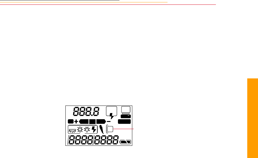
REAR
SLOW
AUTO
ISO
BKT CUSTOM
PC Card icon

1-4
Important Safeguards and Precautions
✔Read Instructions—Read all the safety and operating instructions before
operating your camera.
✔Follow Instructions—Follow all operating and usage instructions.
✔Controls—Adjust only those controls that are covered by the operating
instructions.
✔Heed Warnings—Heed all warnings on your camera and in the operating
instructions.
✔Retain Instructions and Packaging—Retain the safety and operating instructions
for future reference. Retain the packing case for use if your camera needs to be
shipped.
✔Handling—Handle your camera with care. Treat the imager and the anti-aliasing
filter as you would your best lens. Do not drop your camera. Do not place your
camera on an unstable cart, stand, bracket, or table. It can fall, causing serious
injury to persons and serious damage to your camera.
✔Dust—If you operate the camera in environments with excessive dust levels, dust
may accumulate on the camera.
✔Water and Moisture— Do not use the camera in heavy rain or near salt spray and
do not immerse your camera in water or other liquids. Do not use the AC adapter
near water—for example, near a sink, or in a wet room or basement.
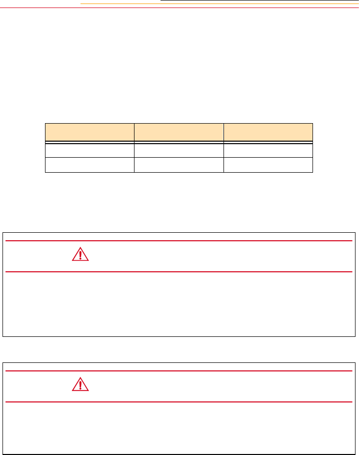
The exclamation point in an equilateral triangle is intended to
alert the user to the presence of important operating and
maintenance (servicing) instructions in the literature accompanying
your camera.

1-5
1
Important Info
✔Object or Liquid Entry—Never push foreign objects of any kind into your
camera openings. The objects could touch dangerous voltage points or short out
parts and cause a fire or electric shock. Never spill liquid of any kind on your
camera.
✔Attachments—Do not use attachments that are not recommended. The use of such
attachments may cause hazards and serious damage to your camera.
✔Power Sources—Operate your camera only from the type of power source
indicated on the name plate of the AC adapter. If you are not sure of the type of AC
power that will be used, consult a dealer or local power company.
✔Overloading—Do not overload power outlets and extension cords; this can result
in a risk of fire or electric shock.
✔Cables—Do not use cables other than those supplied with the camera. Use only the
IEEE 1394 cable supplied with your camera to attach the camera to the computer.
If you use other cables, you may violate FCC emission requirements.
✔Power-Cord Protections—Route power-supply, and other cords, so that you are
not likely to walk on them or pinch them with items placed on or against them. Pay
particular attention to cords at plugs, receptacles, and the point where they leave
your camera.
✔Grounding—The AC adapter is equipped with a three-wire grounding-type plug
with a third (grounding) pin. The three-wire plug will fit into a grounding-type
power outlet. This is a safety feature. If you are unable to insert the plug into the
outlet, contact an electrician to replace the outlet. Do not defeat the safety purpose
of the grounding-type plug.
✔Lightning—For added protection for your camera during a lightning storm, or any
time when you will leave your camera unattended and unused for long periods of
time, unplug the AC adapter from the power outlet and disconnect the camera from
the computer. This will protect your camera from damage caused by lightning or
power-line surges.
✔PC Cards—PC Cards (not supplied with the camera) are fragile devices that can
be damaged if not treated with care. Refer to the documentation accompanying any
PC Cards you obtain to ensure that you are handling the PC Card as specified in
that documentation, and that you are using the PC Card within its operating ranges
for temperature, humidity, condensation, etc.

1-6
✔Humidity, Condensation—We recommend operating your camera within the
range of 8% to 85% relative humidity, non-condensing. If condensation occurs,
added time may be required to read from or write to a PC Card. Condensation may
be present if the camera system and/or PC Cards are moved from a relatively cold
environment (like an air conditioned hotel room), into a warm, humid
environment. We recommend that you allow sufficient time for the camera system
and/or PC Cards to normalize within the specified environmental ranges before
operation. (PC Cards may have more restrictive humidity ranges. Refer to the
specifications that came with your PC Cards.)
✔Servicing—Do not attempt to service your camera yourself. Opening or removing
covers may expose you to dangerous voltage or other hazards and void the
warranty.
✔Damage Requiring Service—Unplug your camera from the wall outlet and
computer, and refer all servicing to the manufacturer under the following
conditions:
• If liquid has been spilled or if objects have fallen into your camera
• If your camera has been exposed to heavy rain or water. (While it is designed to
tolerate a reasonable amount of water, it is not waterproof.)
• If your camera does not operate normally according to the operating
instructions.
• If your camera has been dropped or the housing has been damaged
• When your camera exhibits a distinct change in performance
✔Disassembling the Camera—Never attempt to take the camera apart. The camera
is shipped as a single unit. Do not disconnect the parts (except when cleaning a
dirty anti-aliasing filter or imager). Refer to “Cleaning the Imager” on page 16-8.
1-7
1
Important Info
Electromagnetic Emissions
This equipment has been tested and found to comply with the limits for a Class B digital
device, pursuant to Part 15 of the FCC Rules. These limits are designed to provide
reasonable protection against harmful interference in a residential installation. This
equipment generates, uses and can radiate radio energy and, if not installed and used in
accordance with the instructions, may cause harmful interference to radio
communications. However, there is no guarantee that interference will not occur in a
particular installation. If this equipment does cause harmful interference to radio or
television reception, which can be determined by turning your camera off and on, you can
try to correct the interference by one or more of the following measures:
✔Reorient or relocate the receiving antenna.
✔Increase the separation between your camera and receiver.
✔Connect your camera into an outlet on a circuit different from that to which the
receiver is connected.
✔Consult the dealer or an experienced radio/TV technician for help.
This equipment conforms with the requirements of European Standard EN55022 with
respect to radio interference for a Class B device.
Le present appareil numérique n’émet pas de bruits radioélectriques dépassant les limites
applicables aux appareils numériques de la Classe B prescrites dans les règlements sur le
brouillage redioélectrique édictés par le Ministère des Communications du Canada.
This digital apparatus does not exceed the class B limits for radio noise emissions from
digital apparatus set out in the radio interference regulations of the Canadian Department
of Communications.
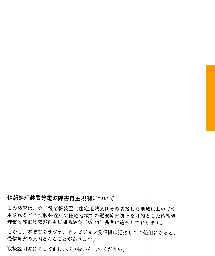
VCCI Statement

INSERT
PHOTO
HERE
2
Your Camera
2-1
About Your Camera
2
Your DCS 600 Series camera (an integration of Nikon and Kodak technologies) provides a
rich set of features that allow you to capture images of the highest quality.
The camera has been designed and built to meet the needs of demanding professionals, for
sports, photojournalism, scientific, industrial, forensic and nearly every other professional
use of photography, as well as high-quality personal photography.
Features
Image quality:
✔DCS 620: 2 million pixel imager (2:3 aspect ratio) operating at 200 - 1600 ISO
DCS 620x: 2 million pixel imager (2:3 aspect ratio) operating at 400 - 4000 ISO
DCS 660: 6 million pixel imager (2:3 aspect ratio) operating at 80 - 200 ISO
DCS 660M: 6 million pixel imager (2:3 aspect ratio) operating at 320 - 800 ISO
✔Anti-aliasing filter to minimize color aliasing or IR filter to improve image quality
✔Enhanced White Balance functionality including ability to save White Balance
settings (not available with DCS 660M)
✔Calibrated exposure and color
✔Large wide cross array with five-area autofocus sensor (Multi-CAM1300) system
(incorporating three cross type sensors) covers wider horizontal and vertical ranges
in the viewfinder than other systems
Image management:
✔Dual active slots for PC Cards
✔JPEG file processing allows you to finish files on the camera (DCS 620 and 620x)
✔Ability to recover deleted images
✔IPTC data in image header
✔Lossless compressed 12-bit raw data for processing with DCS Host software
✔Microphone for recording sound files
✔Transmit data using serial port. Transmit images with a purchasable option

2-2
Image Capture:
✔DCS 620, 620x: 0.5 frame/second continuous frame rate with 3.5 frame/second
burst for 12 images
DCS 660, 660M: 0.15 frame/second continuous frame rate with 1.0 frame/second
burst for 3 images
✔Vertical shooting controls
✔Intervalometer allows you to set your camera to capture a series of images
automatically
✔Global Positioning System option determines the latitude and longitude of the
camera
✔Dynamic Autofocus for moving subjects, and choice of five fixed Single
Autofocus areas
✔Two autofocus modes: Continuous Servo AF and Single Servo AF
Other features:
✔Image LCD panel where you can perform functions such as setting the date/time,
formatting a PC Card, deleting images, displaying a histogram, and specifying
camera properties.
✔Back Status LCD panel displays camera and digital information (white balance,
frame#, remaining frames, battery level, PC Card present, and microphone active).
✔3D Color Matrix Metering
✔Flexible Center-Weighted Meter
✔Custom Settings for added versatility
✔1/300 High-Speed Flash Sync (with Custom Setting; 1/250 sec. and slower at
normal setting)
✔High speed IEEE 1394 serial interface connector
✔AC adapter connector on camera
✔Removable rechargeable battery
✔Self-diagnostic double-bladed shutter tested to over 100,000 cycles
You can attach your camera to one of several computers, then move your images from the
camera to the computer using the DCS Host software included on the DCS Host Software
CD. (Refer to the KODAK PROFESSIONAL DCS Host Software User’s manual, on the
CD.) You can then use the images in other applications or edit them with your image
editing software.
2-3
2
Your Camera
Nomenclature
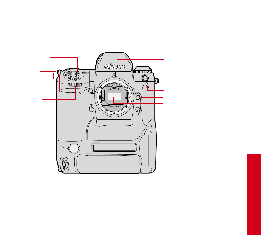
Camera Front
* With firmware version 3.09, or higher, white balance is accomplished using image data
rather than the White Balance sensor.
☛An IR filter is included with the base camera kit. An anti-aliasing filter is included
with the regular kit.
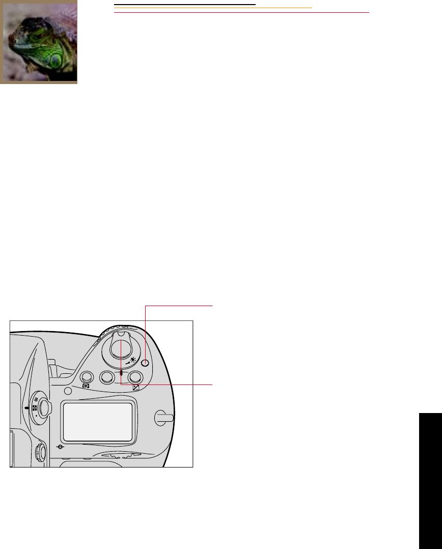
AF Area Mode button
Exposure Mode (MODE)
button
Camera strap eyelet
Exposure Compensation
button
Shutter Release button
Sub-Command dial
Depth-of-field Preview
button
Mirror Lockup lever
White Balance sensor *
Vertical Shutter release
Viewfinder
Drive Mode/Self-timer
selector
Sync terminal
Camera strap eyelet
Self-timer LED
Lens Release button
Anti-aliasing or IR filter
Focus Mode selector
Product label
2-4
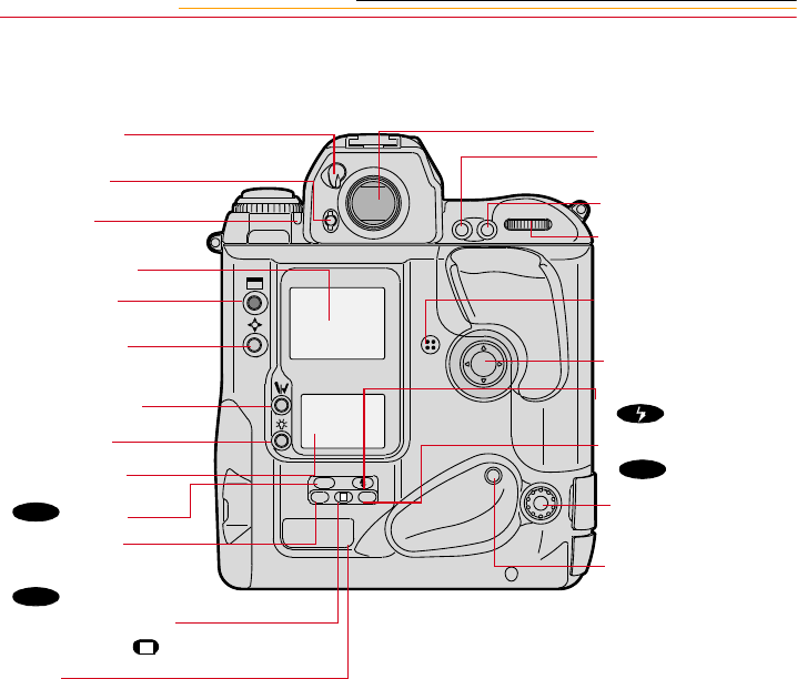
Camera Back
Eyepiece Shutter
lever
Finder Release
button
Alert LED
Image LCD panel
Display button
Selector button
Record/Tag button
White Balance
button
Back Status LCD
panel
()button
Auto Exposure/
Flash Exposure
Bracketing
() button
Shutter Speed/Aperture/
Focus Area Lock button
Label
ISO
BKT
L
L
CSMBKT
ISO
Viewfinder eyepiece
Auto Exposure/
Autofocus Lock button
AF Start (AF-ON) button
Main-Command dial
Microphone
Navigate switch
Flash Sync Mode
() button
Custom Setting Menu
() button
Remote release port
Vertical AF Start (AF-
ON) button
CSM
2-5
2
Your Camera
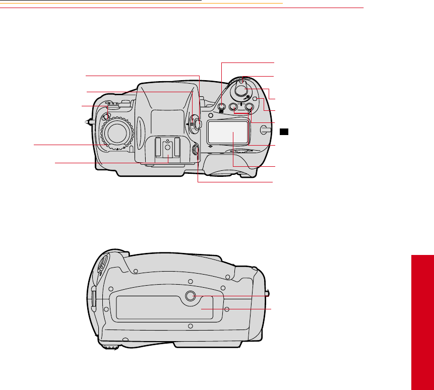
Camera Top
Camera Bottom
C
S
L
MODE
O
O
F
N
F
AF Area Mode button
Power/LCD Panel
Illumination switch
Shutter Release button
Power Switch lock releas
e
Exposure Compensation
button
Exposure Mode (MODE)
button
Top Status LCD panel
Diopter Adjustment knob
+/-
Metering System selector
lock release
Metering System selector
Drive Mode selector lock
release
Drive Mode/Self Timer
selector
Accessory Shoe
Tripod mount
Data plate label
2-6
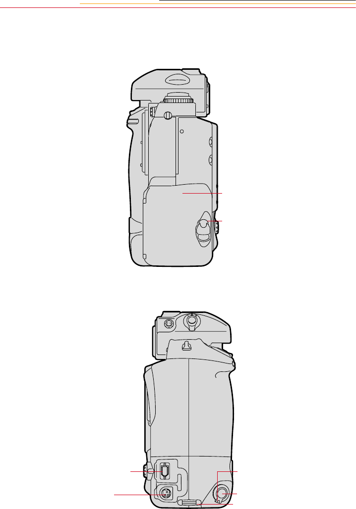
Camera Sides
Battery/PC Card door
Battery/PC Card door latch
IEEE 1394 cable port (cover not shown)
AC Adapter connection (cover not
shown)
Vertical shutter release lock
Vertical Shutter release
Camera strap eyelet
2-7
2
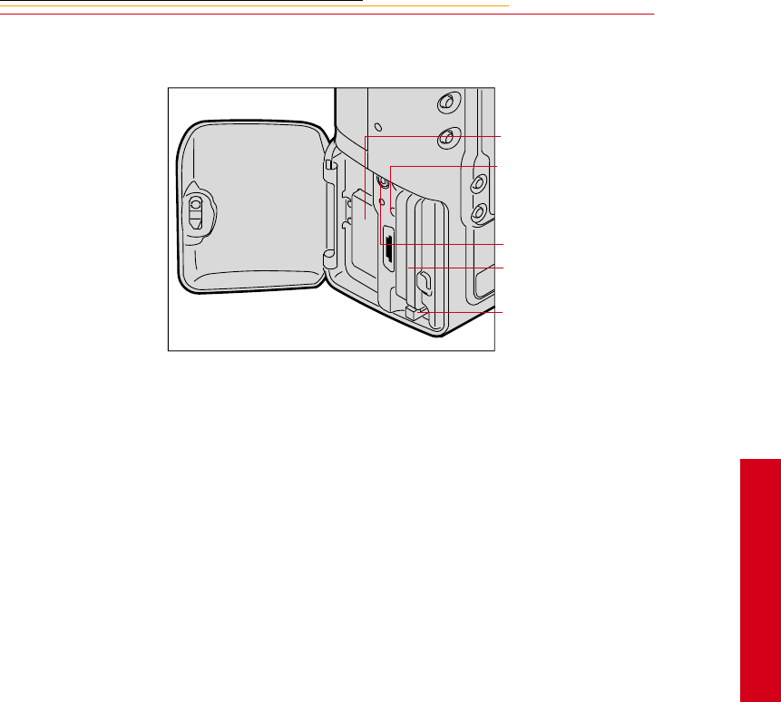
Your Camera
Open Battery/PC Card Door
Battery
Card Busy LED
Serial port
PC Card
Eject button
2-8
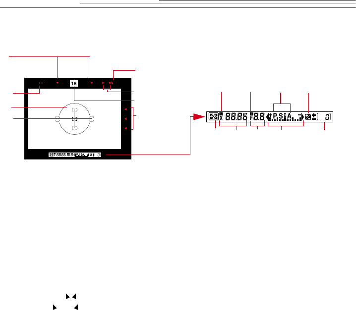
Viewfinder
1
2
3
4
5
6
7
8
9 10 11 12
13 14 15 16 17
1. Focus area indicators
2. Exposure level (for waist-level finder DW-30
or 6x high-magnification finder DW-3i in
manual exposure)
3. Reference circle for Center-weighted
metering
4. Focus brackets/Spot metering
5. Green Ready light
6. Focus indicators: • indicates a subject is in
focus; blinking indicate that autofocus is
impossible; and arrows indicate front and
rear focus respectively
7. Aperture direct readout
8. Focus area indicators
9. Shutter speed lock indicator
10. Aperture lock indicator
11. Exposure mode
12. Exposure compensation
13. Metering system
14. Shutter speed
15. Aperture
16. Electronic analog exposure display
17. Exposure compensation
2-9
2
Your Camera
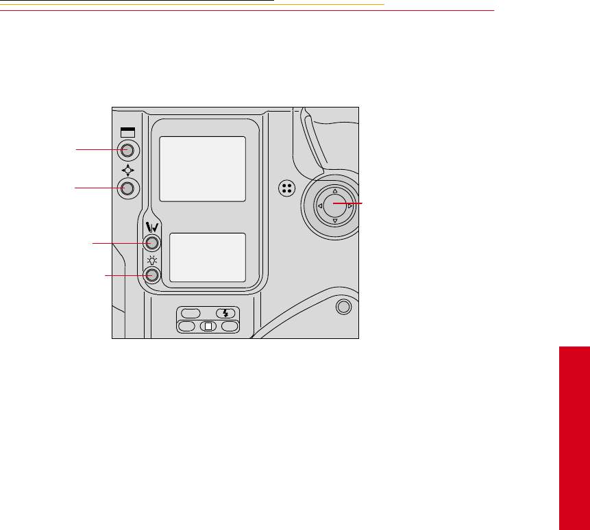
Navigate Switch
The Navigate switch is a four-way rocker switch located on the back of the camera. It is
accessible whether you are holding the camera horizontally or vertically.
Using the Navigate switch to Navigate the Image LCD Panel
The Navigate switch operates in the following manner when you use it with the Display or
Selector buttons (described on the next page):
✔Navigate through images displayed on the Image LCD panel by pressing and
holding the Selector button and pressing the top, bottom, right, or left side of the
switch. Refer to “Image LCD Panel” on page 2-12.
✔Navigate up or down through vertically arranged menu options by pressing and
holding the Selector button and pressing the top or the bottom of the switch.
✔Navigate across the menu bar or through horizontally arranged menu options by
pressing and holding the Display button and pressing the right or left side of the
switch.
Using the Navigate switch to Select the Focus Area
When you use the Navigate switch without the Display or Selector buttons, you can select
the desired focus area. Refer to “Selecting the Focus Area” on page 9-1.
☛If you select Dynamic AF’s primary sensor or the single AF sensor, you can prevent
accidental change by using the Navigate switch with the Focus Area Lock button.
ISO
BKT CSM
L
Navigate Switch
Display button
Selector button
Record/Tag button
White Balance button

2-10
Digital Function Buttons
There are four buttons associated with your camera’s digital functions. You can access the
digital functions when you use these buttons in conjunction with the Navigate switch.
Display Button
✔Press and release the button to turn the Image LCD panel On or Off.
✔Press and hold the button and use the Navigate switch to scroll across the menu bar
icons.
Selector button
✔Press and hold the button and use the Navigate switch to scroll through images or
menu options. Release the button to select the desired image or menu option.
✔Press and hold the Display button and the Selector button at the same time to turn
the Image LCD panel on and display a screen where you can delete the currently
selected image.
Record/Tag Button
✔Press and release the button to tag or untag the selected image. You can tag images
that you do not wish to delete. Refer to “Tagging Images” on page 12-10.
✔Press and hold the button and speak into the microphone to record a sound file and
associate it with the current image. Refer to “Associating Sound Files With
Images” on page 12-11.
White Balance Button
✔Select Preset White Balance then press and hold the button and use the Navigate
switch to select the desired White Balance icon on the Back Status LCD panel.
Refer to “White Balance” on page 8-1.
2-11
2
Your Camera
LCD Panels
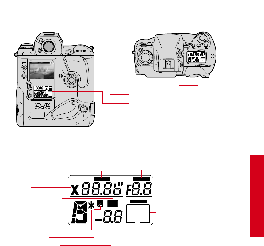
Top Status LCD Panel
L
CSMBKT
ISO
C
S
L
MODE
O
O
F
N
F
REAR
SLOW
AUTO
ISO
BKT CUSTOM
+
LOCK
LOCK
LOCK
BKT
+
Top Status LCD panel
Image LCD panel
Back Status LCD panel
Shutter speed lock
Shutter speed
Auto Exposure/Flash Exposure
bracketing
Exposure mode
Flexible program
Exposure compensation
Exposure compensation value
+
LOCK
LOCK
LOCK
BKT
+
Aperture lock
Aperture
Focus area lock
Focus area/AF area mode
2-12
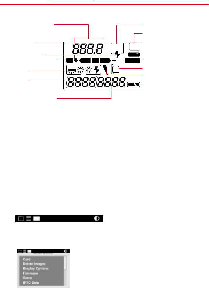
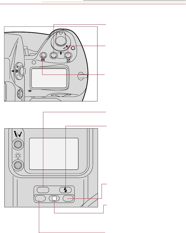
Back Status LCD Panel
Image LCD Panel
The Image LCD panel has been designed for ease of use with maximized space for menu
choices and image-related information.
Menu Bar
The Menu bar is only displayed at your request. When you turn on the Image LCD panel,
the last screen used appears without the Menu bar. If you then press the Display button,
the Menu bar appears.
☛Shortcut: press and hold the Display button to turn on the Image LCD panel and
display the Menu bar.
When the Menu bar is displayed, the remainder of the screen is grayed-out.
Flash sync mode
Personal computer
connection
Custom setting
Card present
Microphone
Battery level
ISO/Bracketing information/
Custom Setting
ISO Setting mode
Bracketing bar graphs
Auto Exposure/Flash Exposure
Bracketing
White Balance
Frame number
Frames remaining on PC Card
REAR
SLOW
AUTO
ISO
BKT CUSTOM
2-13
2
Your Camera
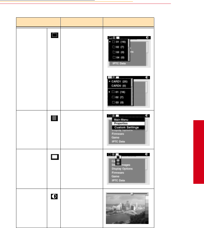
When you select a Menu bar icon, the following screens appear:
Icon Function Dropdown Menu
Folder icon Displays the Folder
dropdown menu. One PC Card:
Two PC Cards:
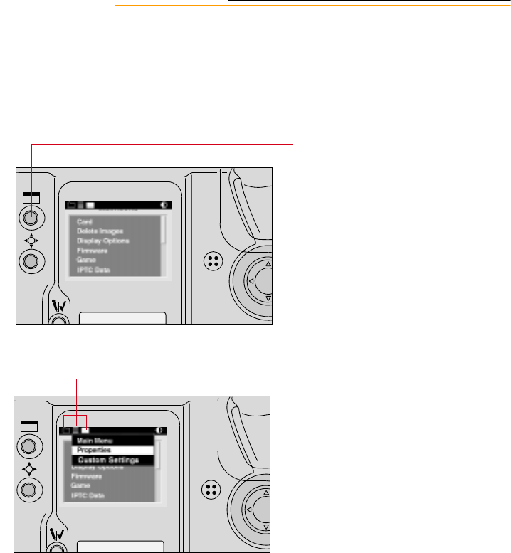
Menu icon Displays a
dropdown menu
with choices for the
Main, Properties,
and Custom Settings
menus.
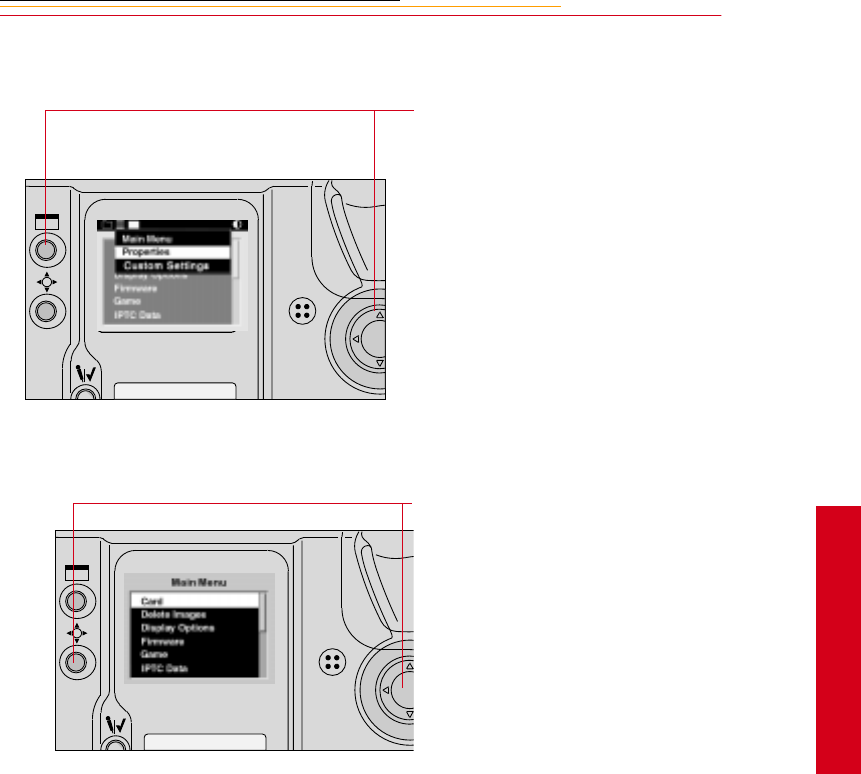
Display icon Displays a
dropdown menu
with choices for
Single, Four, and
Nine Image Review
mode.
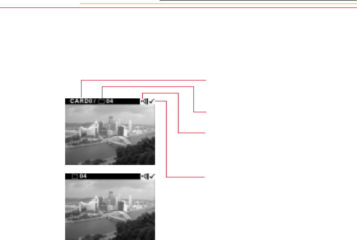
Contrast icon Displays the Display
Contrast screen
where you can
adjust contrast
2-14
Navigation Techniques
Use the following guidelines when navigating the Image LCD panel
To Display the Menu bar and
select a Menu bar icon:
Press and hold the Display button
and use the Navigate switch until
the desired icon is highlighted.
To Display a Dropdown menu:
Highlight the Folder, Menu, or
Display icon, and continue pressing
the Display button until the
dropdown menu appears.
2-15
2
Your Camera
To Choose an item from a
dropdown menu:
Continue to press the Display button
and use the Navigate switch until
the desired menu choice is
highlighted.
To Choose an item from a menu
screen:
Press and hold the Selector button
and use the Navigate switch to
highlight your choice.
2-16
Status Bar
A Status bar appears whenever images are displayed (Single, Four, or Nine Image Review
mode). Information about the currently selected image appears on the Status bar:
The currently active PC Card (if
there are two cards in the camera)
The currently active folder
Sound icon (if one or more sound
files are associated with the selected
image)
Tag icon (if the selected image has
been tagged).
Two PC Cards
One PC Card
2-17
2
Your Camera
Command Dials
Your camera’s Main-Command dial and Sub-Command dial can be used alone or in
combination with other buttons to select various functions or modes.
Main-Command Dial
Use the Main-Command dial by itself or with various buttons to perform the following:
Rotating the Main-Command Dial by Itself
✔Select the shutter speed in
Shutter-Priority Auto or Manual
exposure mode. Refer to
“Shutter-Priority Auto Exposure
Mode” on page 13-1 or “Manual
Exposure Mode” on page 13-8.
✔Perform the Flexible Program in
Programmed Auto exposure
mode. Refer to “Flexible
Program” on page 13-13.
AF-ON
AF-L
AE-L
2-18
Rotating the Main-Command Dial While Pressing Buttons
✔Select Exposure mode. Refer to
“Exposure Mode” on page 8-14.
✔Perform Exposure
Compensation. Refer to
“Exposure Compensation” on
page 13-19.
✔Select AF area mode. Refer to
the “Selecting AF Area Mode”
section on page 9-4.
✔Select ISO. Refer to “ISO” on
page 10-9.
✔Select Flash Sync mode. Refer
to “Flash Sync Mode” on page
11-13.
✔Select the Custom Setting menu.
Refer to “Custom Settings” on
page 13-32.
✔Lock shutter speed/aperture/
focus area. Refer to “Locking
Shutter Speed” on page 13-3.
✔Set or cancel Auto Exposure/
Flash Exposure Bracketing.
Refer to “Auto Exposure/Flash
Exposure Bracketing” on page
13-24.
F
N
F
O
O
MODE
L
CSMBKT
ISO
2-19
2
Your Camera
Sub-Command-Dial
Use the Sub-Command dial by itself or with various buttons to perform the following:
Rotating the Sub-Command Dial by itself
Rotating the Sub-Command Dial While Pressing Buttons:
✔Select the aperture in Aperture-
Priority Auto or Manual
exposure mode. Refer to
“Aperture-Priority Auto
Exposure Mode” on page 13-4
or “Manual Exposure Mode” on
page 8-16.
☛If you are using a non-CPU
lens (without a
microprocessor), you must set
the aperture on the lens’
aperture ring.
✔Set the number of exposures and
compensation value in Auto
Exposure/Flash Exposure
Bracketing. Refer to “Auto
Exposure/Flash Exposure
Bracketing” on page 13-24.
✔Lock the aperture in A mode and
Shutter speed in S mode. Refer
to “Locking the Aperture” on
page 13-7.
✔Select and make a Custom
Setting. Refer to “Making a
Custom Setting” on page 13-32.
MODE
L
CSMBKT
ISO
2-20
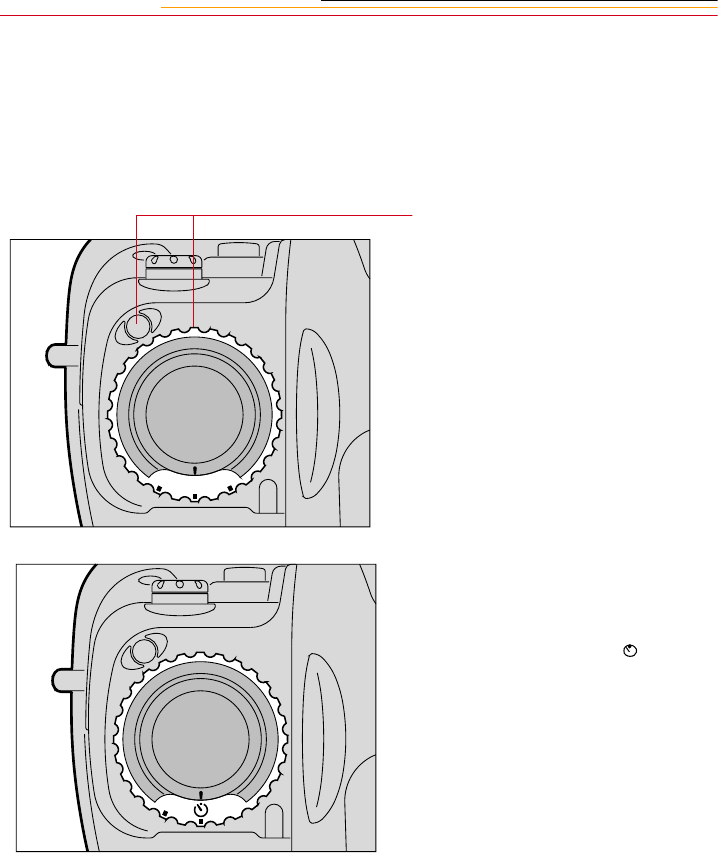
Drive Mode/Self-Timer Selector
This dual-purpose control allows you to select a Drive mode or set the self timer.
When you select a Drive mode, you specify whether one or more images will be captured
when you depress the Shutter Release button.
To set a Drive mode:
Press the lock release for the Drive
mode selector and rotate the Drive
mode/Self-timer selector. Set S for
Single-frame shooting, CL for
Continuous low-speed shooting, CH
for Continuous high-speed shooting
or CS for Continuous silent-low-
speed shooting. Refer to “Drive
Mode” on page 10-10.
To set the Self-timer:
Press the Drive mode selector lock
release and rotate the Drive mode/
self-timer selector to the (self-
timer) position. Refer to “Self-
Timer” on page 13-28.
C
L
H
C
C
S
C
S
2-21
2
Your Camera
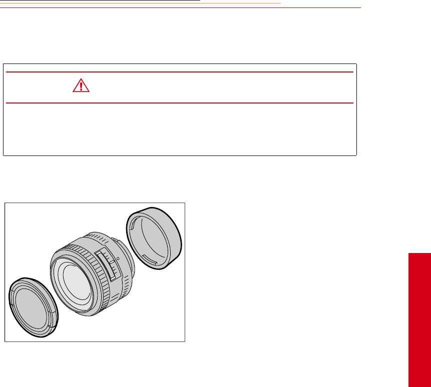
Lens
Refer to Appendix C for a list of lenses that are compatible with your camera.
Mounting the Lens
CAUTION:
Only use lenses that are listed in Appendix C. Other lenses can potentially break
your camera’s anti-aliasing or IR filter. Refer to “Anti-aliasing filter” on page 2-
25.
1Remove the camera body cap
and the front and rear lens caps.
2-22
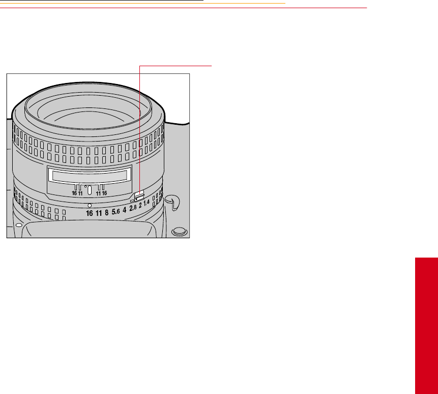
Setting the Lens to the Minimum Aperture
For Programmed Auto or Shutter-Priority Auto mode, use the minimum aperture lock
lever to lock the lens aperture at f/16.
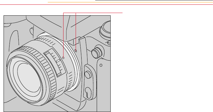
2Position the lens in the camera’s
bayonet mount so that the
mounting indexes on the lens
and camera body are aligned.
Taking care not to press the lens
release button, twist the lens
counterclockwise until it locks
in place.
When mounting or removing a
lens, make sure that the
camera’s power is turned Off.
2-23
2
Your Camera
1Set the lens to its minimum
aperture (f/16).
2Slide the lock lever in the
direction of the aperture ring so
that the white dot on the tab
aligns with the orange dot.
Slide the lock lever in the
opposite direction to release the
lock.
☛Aperture setting operations are
performed using the Sub-
Command dial. Do not move
the lens aperture once it is set
to its minimum aperture.
☛The aperture can also be set
with the lens aperture ring in
Aperture-Priority Auto or
Manual Exposure mode. In
these cases the aperture can
only be verified through
aperture direct-readout.
2-24
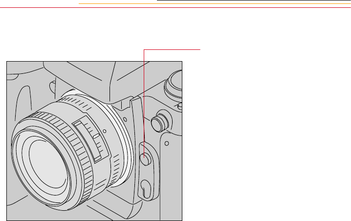
Removing the Lens
Press and hold the Lens Release
button and turn the lens clockwise.
☛If you don’t plan to mount a
lens for a while, attach the
supplied BF-1A body cap.
(The BF-1 body cap cannot be
used on your camera.)
2-25
2
Your Camera
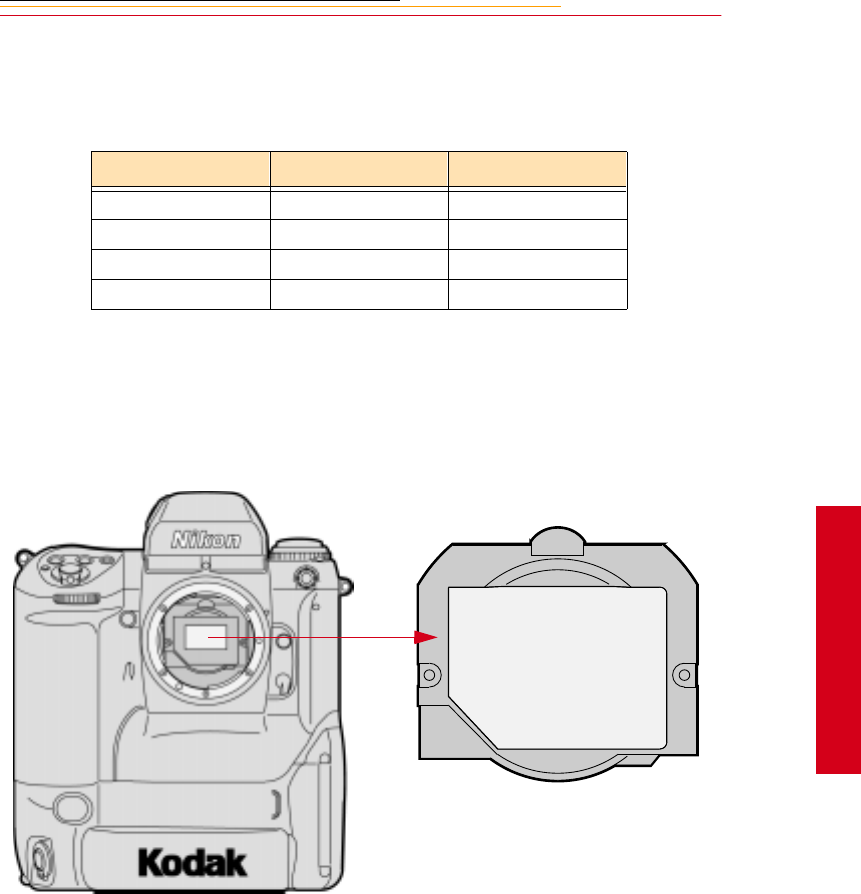
Imager
The imager records light when you capture an image. The imager size and ISO varies,
depending on your camera model.
Anti-aliasing filter
The DCS 620, DCS 620x, and DCS 660 cameras each contain an anti-aliasing filter which
improves overall image quality and helps reduce aliasing at certain focal distances.
IR Filter
The DCS 660M and some DCS 620 cameras (base camera kits) use an IR filter in place of
an anti-aliasing filter.
Camera Imager Size ISO
DCS 620 2 million pixels 200 - 1600
DCS 620x 2 million pixels 400 - 4000
DCS 660 6 million pixels 80 - 200
DCS 660M 6 million pixels 320 - 800
2-26
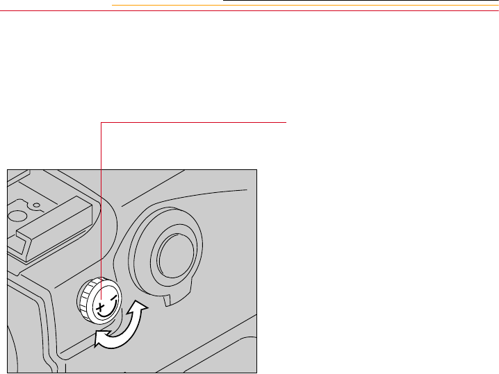
Viewfinder Diopter
You can compensate for near- or far-sightedness and see more clearly through the
viewfinder by adjusting the finder diopter within a continuous range of from –3 to +1.
1Pull the Diopter Adjustment
knob and rotate it in either
direction until the focused image
in the viewfinder’s reference
circle appears sharp
2Push the knob back in to lock.
2-27
2
Your Camera
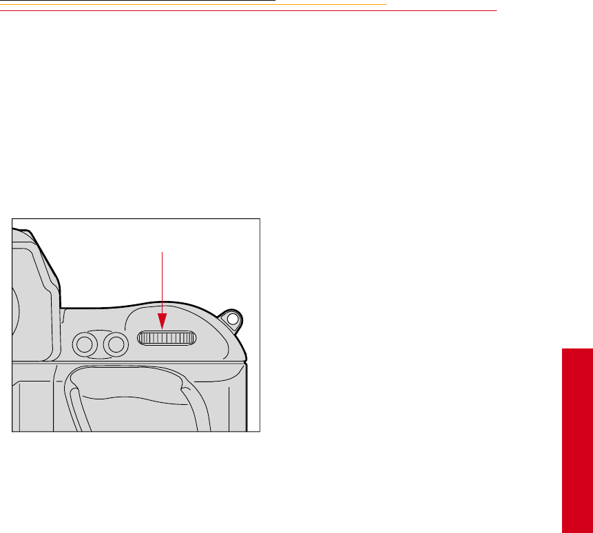
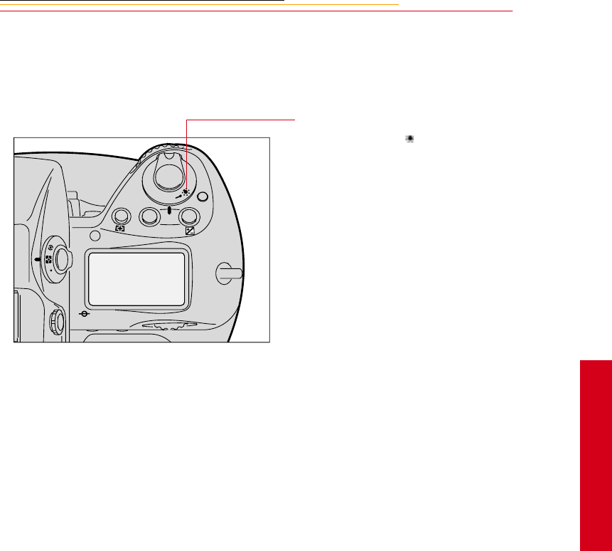
Illumination Switch
You can illuminate the Top and Back Status LCD panels for easy viewing at night or in
low light situations.
Rotate the LCD Panel Illumination
switch toward the to illuminate
the Top and Back Status LCD
panels.
The LCD panel illumination switch
automatically returns to the on
position, and the LCD panels
remain illuminated as long as the
meter is on. (You can change the
time that the meter remains on using
custom setting #15. Refer to
“Custom Settings” on page 13-32.)
To turn the illumination off before it
times out, rotate the LCD Panel
Illumination switch clockwise
again.
After the shutter is released, the
LCD panel illumination
automatically turns off.
F
N
F
O
O
MODE
2-28
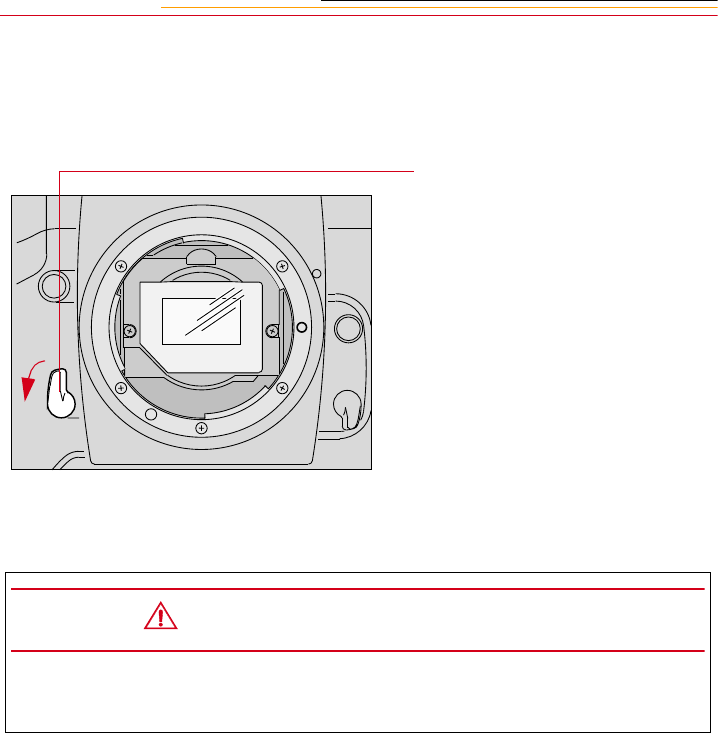
Mirror Lockup Lever
When using super-telephoto lenses or performing photomicrography, it is necessary to
reduce camera vibration to the absolute minimum.
Lock the reflex viewing mirror in
the up position by rotating the
mirror lockup lever
counterclockwise until it stops.
☛When the mirror is locked up,
you cannot operate the camera
in any Auto Exposure or
autofocus mode, even though
the viewfinder LCD may
indicate otherwise. Any
indication of light in the LCD
is a result of light entering
through the viewfinder
eyepiece.
CAUTION:
Do not to leave the camera in direct sunlight when the reflex mirror is locked in
the up position. The sunlight may damage the shutter curtain.
2-29
2
Your Camera
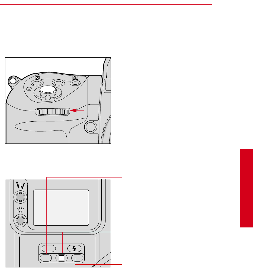
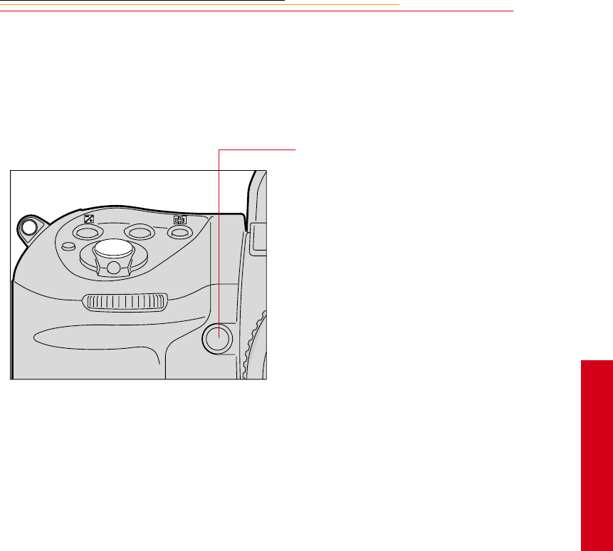
Depth-of-Field Preview Button
The depth of field is the zone of acceptable focus in front of and behind the subject. You
can preview this zone using the Depth-of-Field Preview button.
The Depth-of-Field Preview button will not work properly if there is no PC Card inserted.
In Aperture-Priority Auto or
Manual Exposure mode, press the
Depth-of-field Preview button to
stop the lens down to the aperture
that was set with the Sub-Command
Dial.
In Programmed Auto or Shutter-
Priority Auto Exposure mode, the
lens will be stopped down to the
automatically set aperture. When
you press the Depth of Field
Preview button, the viewed image
becomes progressively darker as the
aperture gets smaller. Those
portions of the image that appear in
focus when the button is pressed are
within the depth of field.
Be aware of the following when
using the Depth of Field Preview
button:
✔When using lenses with a meter
coupler, it is not possible to
attain correct exposure because
exposure must be determined by
full-aperture metering.
✔Do not use the Spot Metering
system when using the Depth-
of-Field Preview button.
✔During preview, the aperture
cannot be adjusted and
autofocus is not possible.
MODE
2-30
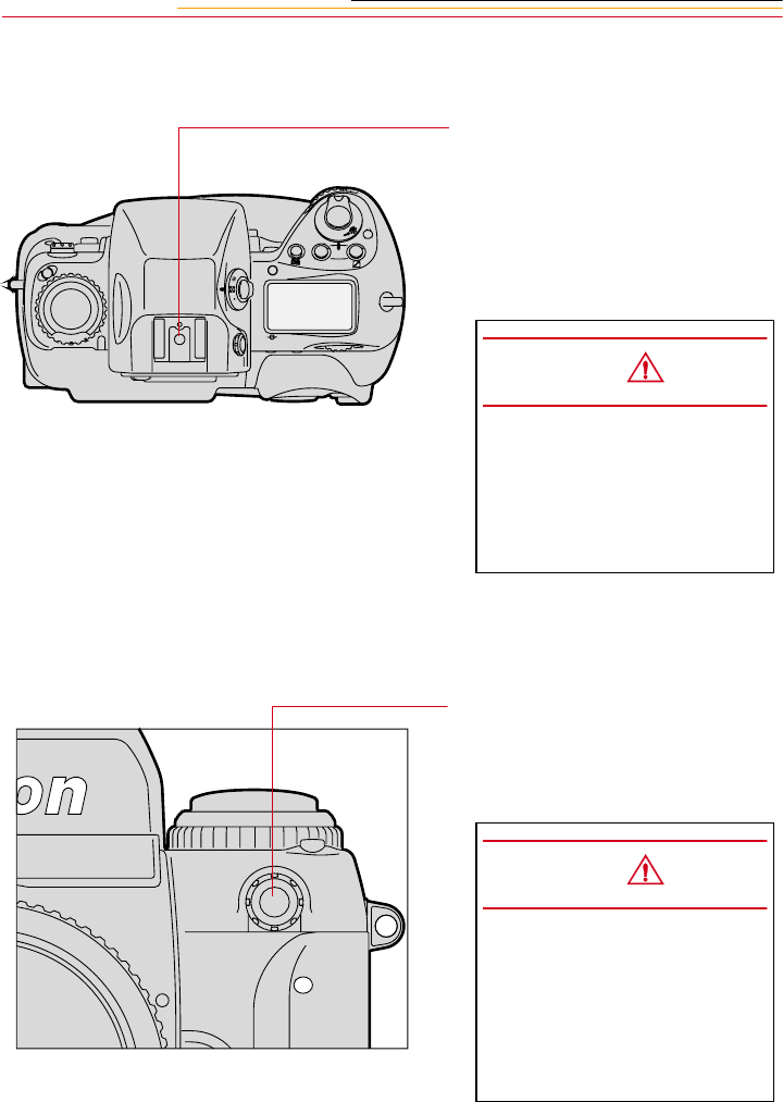
Accessory Shoe
Sync Terminal
Located at the top of the Multi-
Meter Finder, the ISO-type hot shoe
allows direct mounting of a wide
range of Nikon-dedicated electronic
Speedlights. Refer to “Attaching the
SB-28D or SB-28DX” on page 11-
3.
Your camera features a separate
sync terminal that accepts all flashes
with standard PC-type, plug-in sync
cords.
C
S
L
MODE
O
O
F
N
F
CAUTION:
Do not use speedlights from
other manufacturers since
higher voltages and/or extra
hot shoe contacts can damage
your camera.
CAUTION:
Flashes with excessive trigger
circuit voltage can damage
your camera. Consult your
service representative for
questions on compatible
flashes.
2-31
2
Your Camera
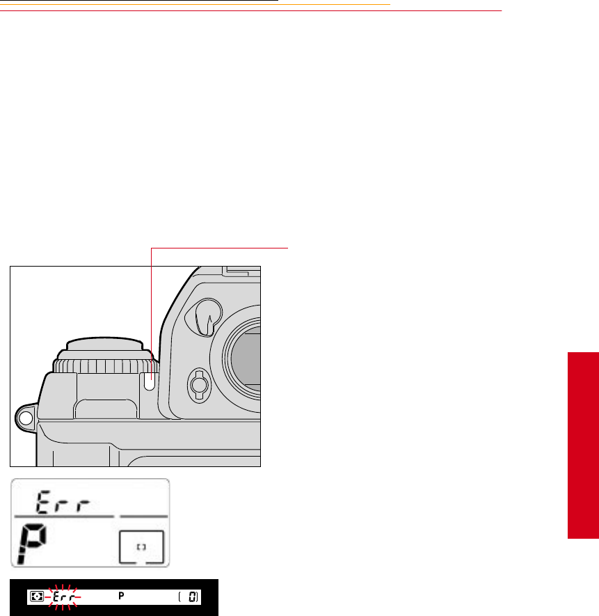
Self-Diagnostic Shutter System
Your camera is equipped with a self-
diagnostic shutter that automatically
controls the shutter speed for each
release of the shutter.
The self-diagnostic shutter
automatically detects inaccuracies
in performance and readjusts the
shutter speed accuracy for
subsequent image capture.
If a malfunction occurs or the
shutter curtain fails to operate, the
alert LED blinks and Err blinks in
the Top Status LCD panel and
viewfinder. Turn the camera power
Off, then On. Refer to “Turning the
Camera On and Off” on page 3-1. If
the blinking stops, the malfunction
is corrected. If the alert LED and Err
resume blinking, turn the power off
and take the camera to your service
representative.
2-32
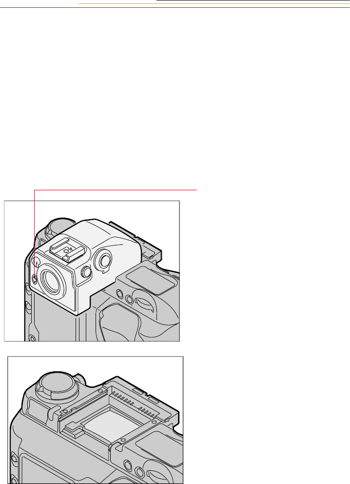
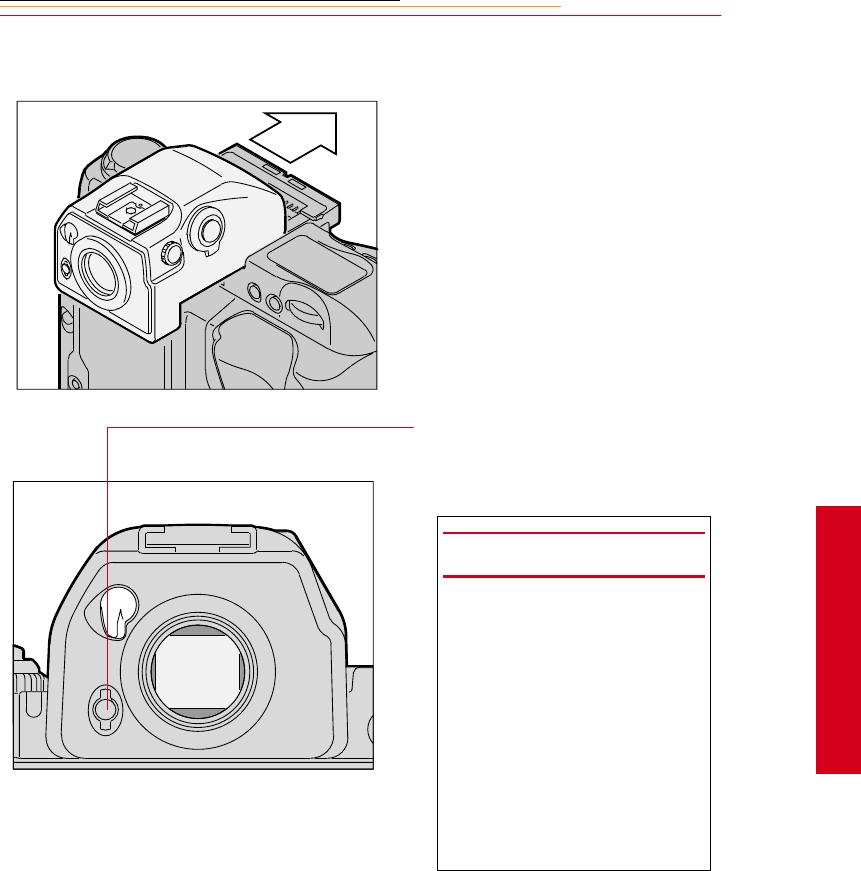
Changing Viewfinders
A modified DP-30 viewfinder is included with the DCS 620 and 620x cameras. (A
standard DP-30 viewfinder is included with the DCS 660 and 660M cameras.) See
Appendix C for a list of compatible viewfinders. Using other viewfinders with your
camera can decrease the “active area” of the viewfinder.
Removing the Finder
1Turn the camera off. Refer to
“Turning the Camera On and
Off” on page 3-1.
2Press and hold the Finder
Release button.
☛This button is metallic gray on
the DCS 620 and 620x
cameras and black on the DCS
660 and 660M cameras.
3Slide the viewfinder away from
the lens.
2-33
2
Your Camera
Attaching the Finder
Slide the finder in until it clicks in
place.
4Be sure that the Finder Release
button has returned to its
original position.
IMPORTANT:
Be sure the viewfinder is
attached when you are capturing
images. If the shutter is released
without a viewfinder attached,
stray light may enter through the
focusing screen.
When removing a viewfinder, be
careful not to leave smudges or
fingerprints. Place the detached
viewfinder on a soft, clean cloth.
2-34
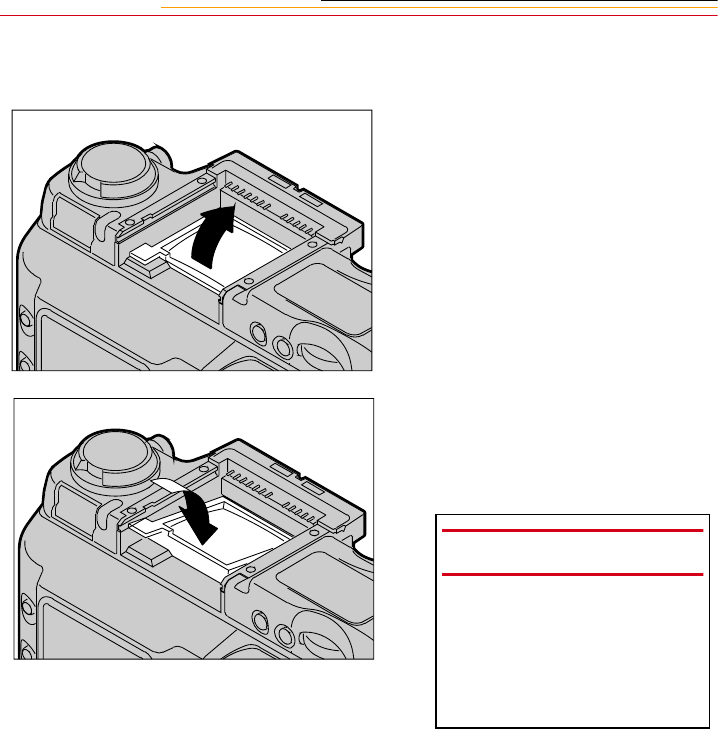
Changing Focusing Screens
1Turn off the camera and remove
the finder. Refer to “Removing
the Finder” on page 2-32.
2Insert your fingernail under the
rear edge of the focusing screen
and lift the screen out.
3To install a focusing screen,
insert the front edge under the
central ridge, then push the rear
edge down into place.
IMPORTANT:
When removing a focusing
screen, be careful not to leave
smudges or fingerprints. Place
the detached screen on a soft,
clean cloth.
2-35
2
Your Camera
Camera Straps
A neck strap and a hand strap are included with your camera. You can attach either or
both.
Attaching the Neck Strap
Thread the ends of the neck strap
through the strap fixtures. Pull
firmly on the strap to make sure it is
held securely by the buckles.
2-36
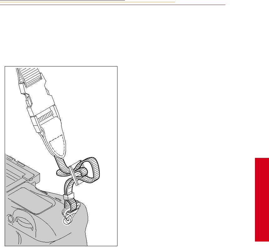
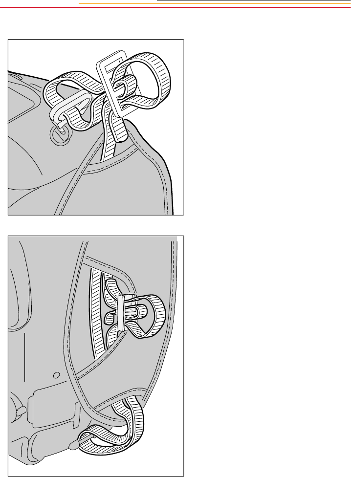
Attaching the Hand Strap
1Thread the strap through both
loops in the hand strap pad.
2Place the three-holed buckle on
the strap and thread through the
camera’s top strap fixture.
3Thread the other end of the strap
through the camera’s bottom
strap fixture.
4Thread the top strap back
through the buckle as shown.
5Thread both ends of the strap
back through the loops on the
hand strap pad.
6Place the two-holed buckle on
the top strap.
7Tuck the top strap through the
bottom loop in the hand strap
pad.
8Thread the bottom strap through
the two-holed buckle as shown.
9Tuck the bottom strap through
the top loop in the hand strap
pad.

2-37
2
Your Camera
Name Plate
Using the DCS Acquire Module or DCS TWAIN Data Source, you can enter text that
appears in certain screens on your camera. The Name Plate is useful for personalizing
your camera, for example, “This camera belongs to Joe Smith”.
In the DCS Acquire Module or DCS TWAIN Data Source:
1Click the Camera Control button.
The Camera Control dialog box appears.
2Click the Properties button.
The Properties dialog box appears.
3Scroll through the list and select the Name Plate property.
4Enter up to 50 characters of text in the Name Plate text box.
The text appears in the following screens on the camera’s Image LCD panel:
✔No images in folder
✔No images in memory
✔No card in camera
INSERT
PHOTO
HERE
3
Power
3-1
Powering Your
Camera
3
Operate your camera using either battery or AC power. You can preserve battery power by
using the AC adapter whenever possible.
You can charge your camera batteries using a battery charger and an international power
cord set. These items are included with most cameras (except base camera kit). They are
also available from Kodak as accessories. The power cords allow you to use the AC
adapter and the battery charger in Australia, Great Britain, Germany, Japan, and the
United States.
Turning the Camera On and Off
1Press and hold the Power Switch
Lock release.
2While continuing to press the
Power Switch Lock release,
rotate the Power switch
clockwise to turn the camera On
and counter-clockwise to turn
the camera Off.
F
N
F
O
O
MODE
3-2
Batteries
Your camera can use either NiMH (nickel metal hydride) or NiCd batteries. Extended
camera metering, autofocus, or extensive LCD panel operation reduces the number of
images available from a full battery charge.
With a fully charged battery, the camera can provide up to the following number of
images:
☛Battery performance deteriorates in temperatures below 32°F (0°C). Keep the
camera and a spare battery close to your body or in an inside pocket to keep it warm
until use.
Camera NiMH battery NiCd battery
DCS 620 and 620x 1000 300
DCS 660 and 660M 300 100
WARNING:
Batteries can explode or cause burns if disassembled, shorted, exposed to high
temperatures, or disposed of in fire. Be sure to observe all precautions indicated on
the battery package. Always keep batteries out of the reach of children and return
them to your camera dealer for recycling when you are finished with them.
CAUTION:
If you don’t plan to use your camera for five or more days, remove the battery
from the camera and carrier. This will prevent battery discharge, and/or damage
due to battery leakage.
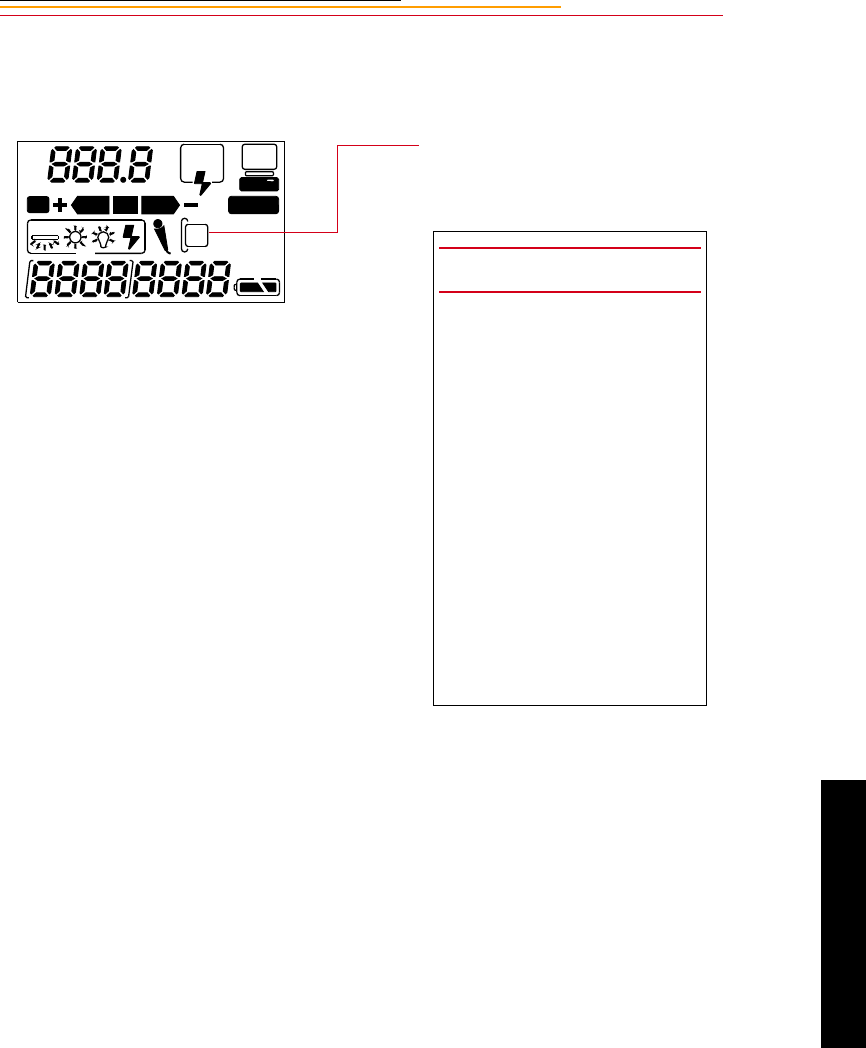
3-3
3
Power
Inserting/Removing Batteries
☛You must charge a battery before using it for the first time.
1Check that the Card Present icon
on the Back Status LCD panel is
not blinking.
2Turn off the camera.
REAR
SLOW
AUTO
ISO
BKT CUSTOM
IMPORTANT:
If the Card Present icon or the
Card Busy LED inside the
Battery/PC Card door are
blinking, wait until the blinking
stops before continuing. (You
can lose data if you remove the
battery while the card is busy.)
Turn off the camera before
changing batteries, otherwise
the camera can “lock up” and
stop you from doing anything. If
this happens, turn off the
camera, remove the new battery,
wait 10 seconds, insert the new
battery, then turn on the camera.
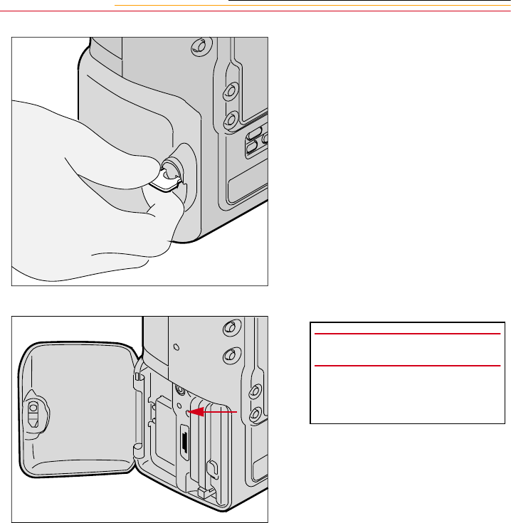
3-4
3Lift the latch assembly on the
Battery/PC Card door and turn it
counter-clockwise to open the
door.
IMPORTANT:
Be sure that the Card Busy LED
is Off before you continue.
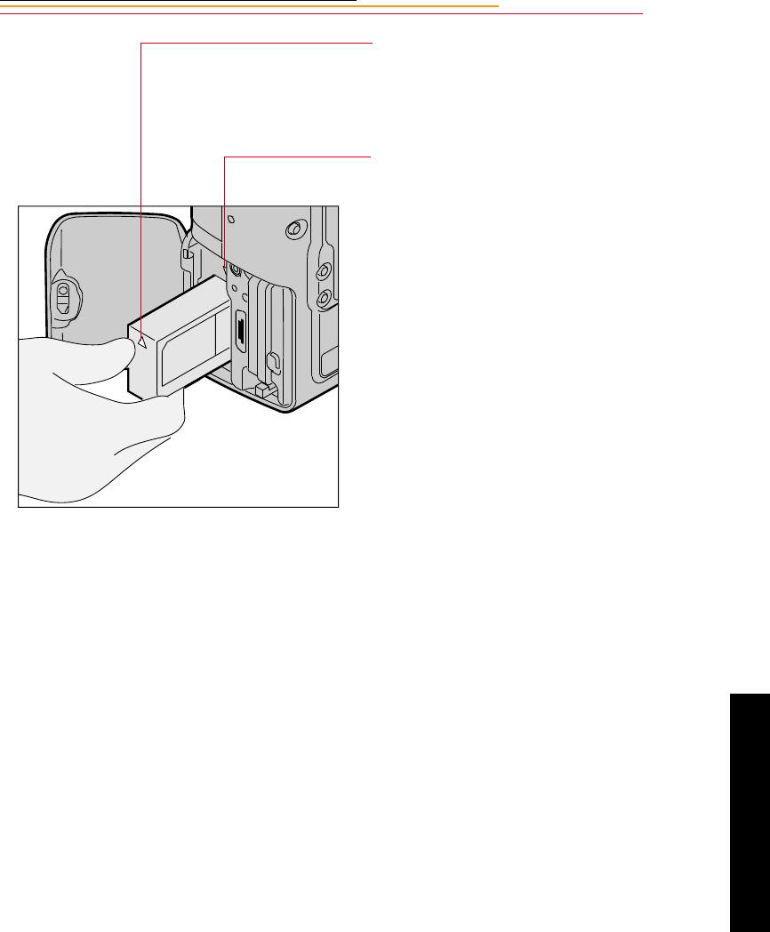
3-5
3
Power
The white arrow opposite the
connector should be pointing
upwards as the battery is
inserted.
Some (not all) cameras have a
white arrow pointing
downwards (towards the camera
bottom) just above the battery
compartment. If your battery
and your camera both have the
arrows, then the arrows should
be aligned as you insert the
battery into the camera.
4To insert: slide the battery to the
back of the battery slot and press
firmly in place.
To remove: slide the battery out
of the battery slot.
5Close the Battery/PC Card door.
6Turn the latch assembly
clockwise and return it to its flat
position.
☛You can insert or remove a
battery while the camera is
connected to an AC adapter
for camera. Refer to “AC
Adapter for Camera” on page
3-13.
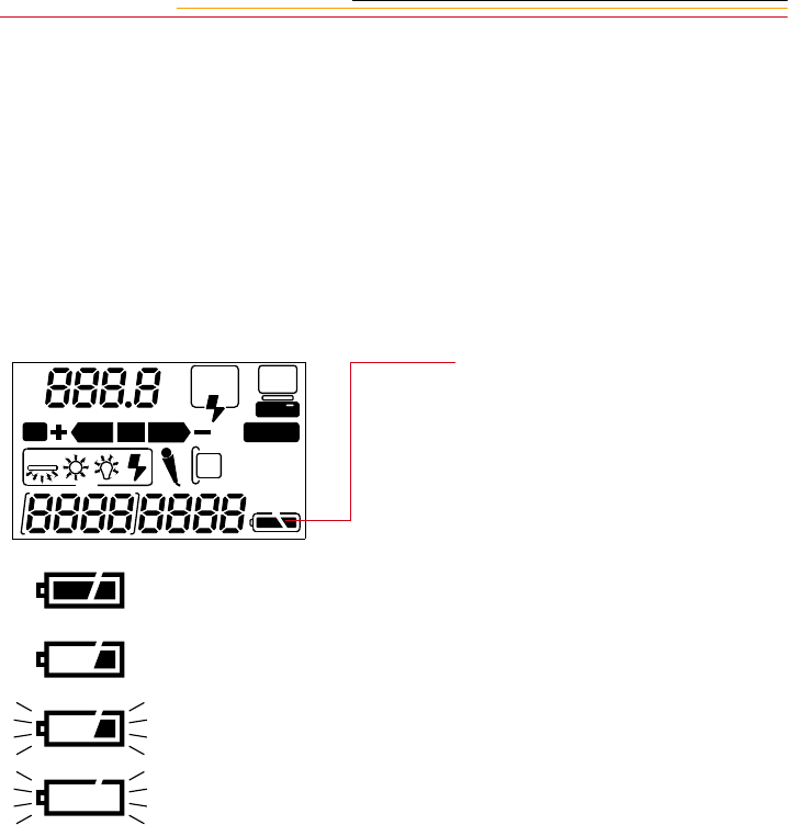
3-6
Checking Battery Status
You can determine whether a battery needs charging by viewing the Battery icon on your
camera’s Back Status LCD panel. (If the camera is using an AC adapter, the Battery icon
is not displayed.)
Always check the battery status at the following times:
✔When loading a new battery
✔After lengthy storage
✔If the shutter will not release
✔In cold weather
✔Before an important assignment
1Insert a battery if there is not one
in the camera. Refer to
“Inserting/Removing Batteries”
on page 3-3.
2Turn on the camera.
3Check the Battery icon on the
Back Status LCD panel.
The icon indicates whether the
battery needs changing.
☛If the icon indicates that the
battery is empty, the camera
will not capture images.
REAR
SLOW
AUTO
ISO
BKT CUSTOM
Full
Low
Insufficient
Empty
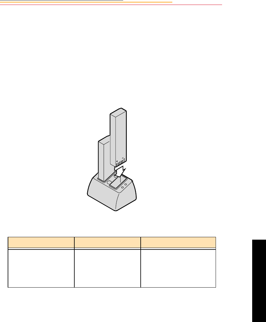
3-7
3
Power
Battery Charger
You need to charge a battery before using it for the first time and whenever it is low. If you
plan to use your camera without the AC adapter for an extended period of time, it is a good
idea to charge one or more batteries before you begin. An external battery charger is
included with your camera.
For the best results, store and use the battery charger within the following temperature
ranges:
Storage temperature range: -25°C to 70°C (-77°F to 158°F)
Charging temperature range: 0°C to 45°C (32°F to 113°F)
The battery charger has two slots. A yellow and a green light near the slots illuminate to
indicate the status of the batteries:
* While you can use a battery when the light turns green, you will have optimal results if
you leave the battery in the charger for 2 hours after the light turns green.
Yellow light Green light Battery Status
Off
On
Off
Slow Flashing
Fast Flashing
Off
Off
On *
Off
Off
No battery inserted
Charging
Fully charged
Conditioning (Discharging)
Error
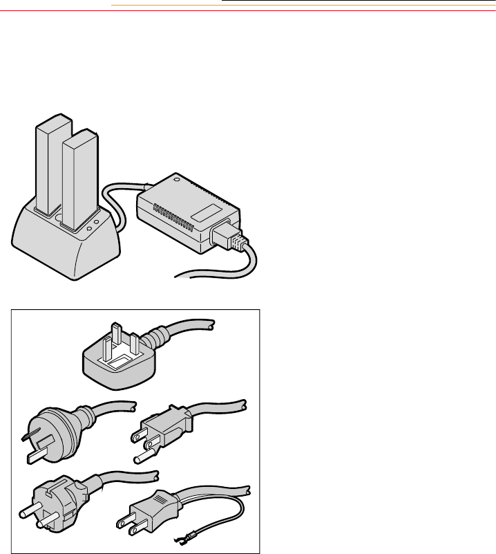
3-8
Charging Batteries
1Remove the battery from the
camera (page 3-3).
2Plug the cable from the AC
adapter for charger into the
battery charger jack.
3Select the international power
cord that is appropriate for your
area.
4Insert the appropriate end of the
international power cord into the
receptacle on the rear of the AC
adapter for charger.
5Plug the power cord into a wall
outlet.
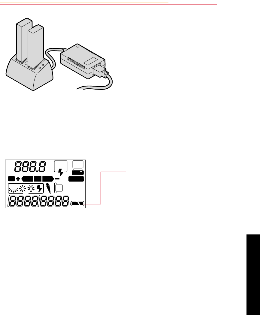
3-9
3
Power
If your battery charger does not function as expected, check the following:
✔The wall adapter is properly connected.
✔There are no foreign objects lodged in the pockets.
✔The batteries are inserted so that they properly mate with the connector in the
bottom of the pocket.
☛No harm will come to your batteries if you leave them in the charger for an extended
period of time.
6Insert one or two batteries in the
slots in the battery charger.
☛If you are charging one
battery, you can use either slot.
On average, a battery is charged
in approximately one hour. If
two batteries are inserted, they
are charged simultaneously.
7Once the green light turns on,
wait four hours, then remove the
battery or batteries from the
charger.
If you don’t wait two hours,
batteries will only be charged to
80% of capacity.
8Insert a charged battery into the
camera.
9Close the camera door.
The Battery icon is displayed on
the Back Status LCD panel
when a battery is in the camera,
the camera is turned on, and the
camera is not in PowerSave
mode (page 3-11).
☛The Battery icon is not
displayed if the AC adapter is
connected.
REAR
SLOW
AUTO
ISO
BKT CUSTOM
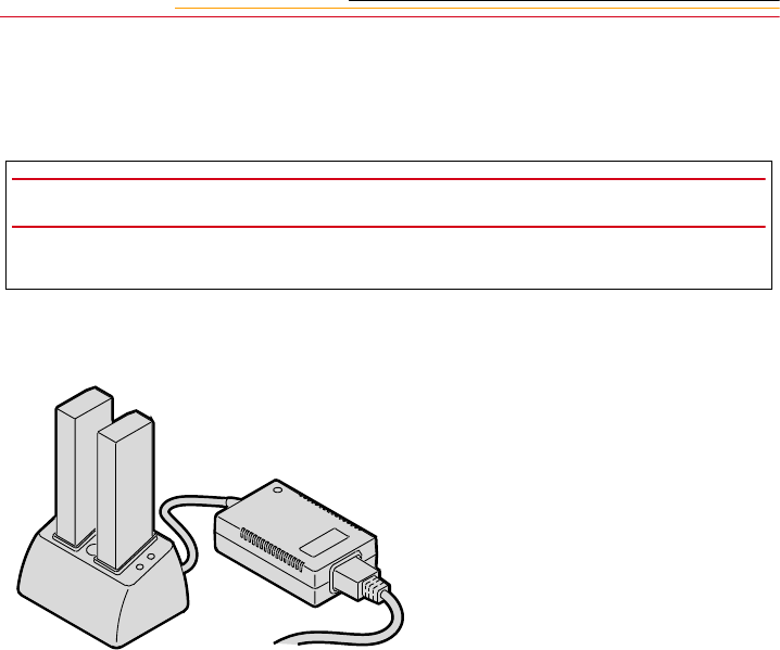
3-10
Conditioning (Discharging Batteries)
You may occasionally need to condition a battery. You would only do so if a battery
provides a noticeably shorter run time (less than 50% of normal capacity).
☛You can condition a battery in one slot while charging a battery in the other.
IMPORTANT:
Don’t condition your batteries too often or they will wear out prematurely.
1Insert one or two batteries into
the slots on the top of the battery
charger.
2Press the Condition buttons
associated with the batteries that
you wish to condition.
The batteries will first be
conditioned, then charged. The
whole process can take up to
5 1/2 hours.
3Remove the batteries from the
battery charger four hours after
the green light turns on.
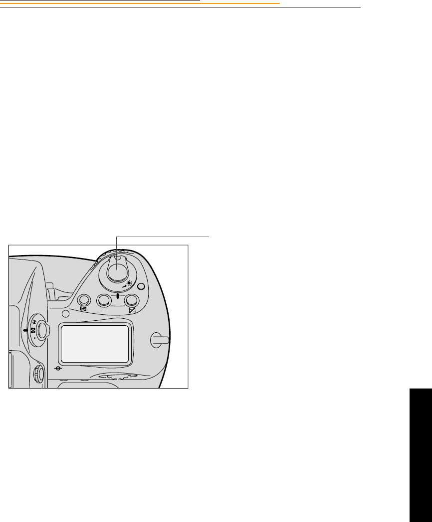
3-11
3
Power
Battery Conservation
Your camera has several built-in functions that minimize drain on your battery.
PowerSave Mode
☛If your camera is powered by an AC adapter or is connected to a computer with
IEEE 1394 cable, it will not enter PowerSave mode.
If you don’t use your camera for 30 minutes, it will enter PowerSave mode (go to sleep).
In PowerSave mode, the flash will not be kept charged and the backlight for the Top Status
and Back Status LCD panels will turn off.
☛You can change the setting for PowerSave time. Refer to “Setting PowerSave Time”
on page 4-3.
Waking your Camera from PowerSave Mode
Lightly press the Shutter Release
button.
F
N
F
O
O
MODE
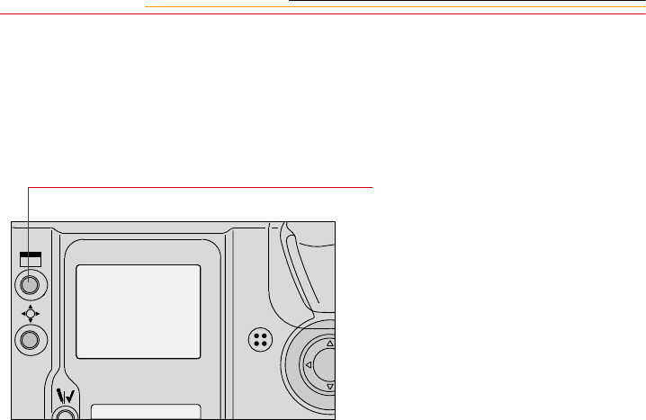
3-12
Image LCD Panel Timeout
The Image LCD panel will turn off if you have not used the camera for 60 seconds.
☛You can change the setting for Image LCD timeout. Refer to “Setting Display Off
Time” on page 4-3.
Meter Timeout
Your camera’s meter remains on for 8 seconds after you lightly press the Shutter Release
button.
☛You can change the setting for meter timeout. Refer to “Making a Custom Setting”
on page 13-32.
When the meter times out, the following turn off:
✔Viewfinder LCD
✔Top Status LCD panel
Situations Using Extra Battery Power
✔Use of a telephoto or wide angle fisheye lens and constant auto-focusing
✔Frequent use of the Image LCD panel
✔Cold temperatures
✔Turning the camera on and off frequently
Press the Display button to turn the
Image LCD panel On again.
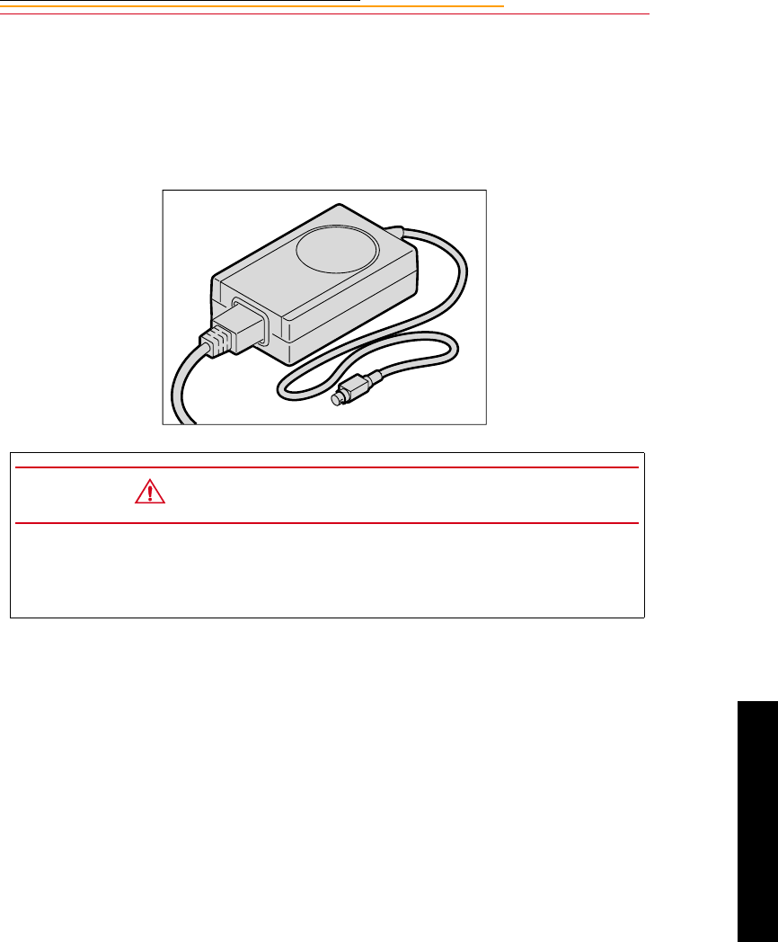
3-13
3
Power
AC Adapter for Camera
Use an AC adapter whenever possible to lessen drain on the battery. You should also use it
when your camera is connected to a computer to prevent loss of power if the battery
should lose its charge.
Tips
✔Use only the KODAK AC adapter; do not plug other chargers or adapters into the
camera.
✔The AC adapter is for indoor use only.
✔Do not use the AC adapter for any purpose other than for the camera.
✔The AC adapter does not have an On/Off switch. To turn off the AC adapter, you
will need to unplug it
CAUTION:
Operate the equipment only from the type of power source indicated on the AC
adapter. A line voltage outside of this range can destroy the AC adapter and/or
the camera.
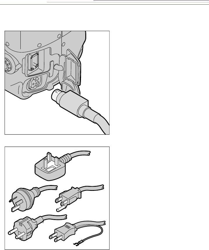
3-14
Connecting the AC Adapter for Camera
1Open the connector cover at the
side of the camera.
2Plug the AC adapter for camera
into the AC Adapter connection.
3Select the international power
cord that is appropriate for your
area.
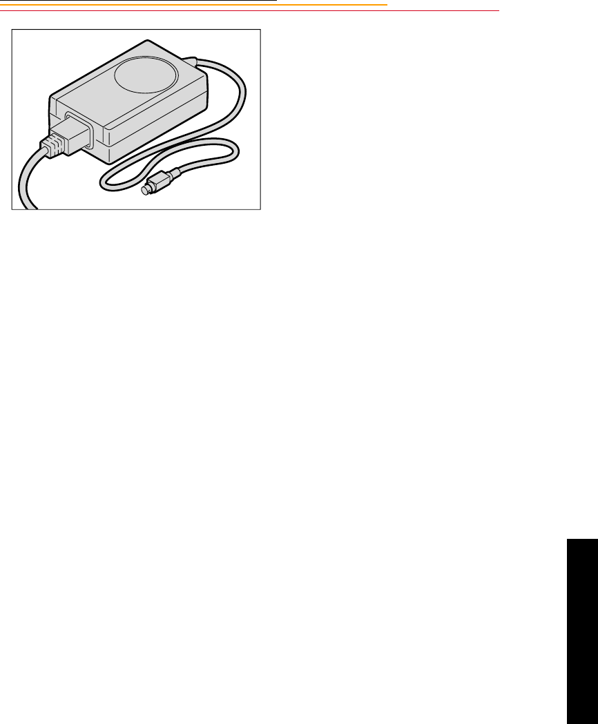
3-15
3
Power
4Plug the appropriate end of the
power cord into the AC adapter
for camera.
5Plug the power cord into a wall
outlet.
☛You can connect or disconnect
the AC adapter while a battery
is in the camera.
☛The AC adapter for camera
will NOT charge a battery in
the camera.

INSERT
PHOTO
HERE
4
Configuring
4-1
Configuring Your
Camera
4
This section describes how to change various camera settings.
Date and Time
You can set the date and time. The format for the date is year/month/day, and the format
for time is hour:minute:second based on a twenty-four-hour clock.
The setting is maintained when you turn off the camera, after PowerSave, or when you
remove the battery for a few days.
☛There is a small rechargeable battery in the camera which can lose its charge if you
remove the main battery for a long period of time. When you insert the main battery,
the small battery is recharged, but you will need to reset the date and time.
1Select the Menu icon, then
choose Main Menu from the
dropdown menu. Refer to
“Navigation Techniques” on
page 2-14.
2Select Date/Time from the Main
menu.
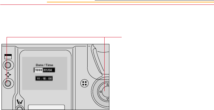
4-2
The Date/Time screen appears.
There are six fields: year, month,
day, and hour, minutes, seconds.
3Press and hold the Selector
button and press the left or right
side of the Navigate switch to
highlight the desired field.
4Press and hold the Selector
button and press the top or
bottom of the Navigate switch to
change the highlighted field.
☛When you hold the Selector
button to highlight the
Seconds field, the seconds
stop counting and you can
reset the field. The counting
resumes when you release the
button.
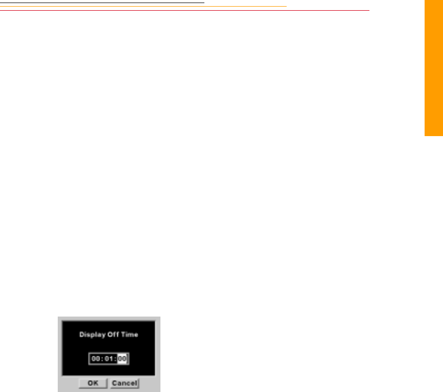
4-3
4
Configuring
Camera Properties
You can set the following camera properties using camera controls: Display Off time,
Powersave time, Resolution, Enable Sharpening, Use FOLDER01,and Total Actuations.
☛The list of properties may change as new versions of firmware become available.
The wording in the screens may not be exactly as shown.
Setting Display Off Time
You can change the Display Off time (the length of time before the Image LCD panel
turns off). Extended use of the Image LCD panel can drain your battery.
The Display Off Time screen (and the PowerSave screen) operate a little differently than
the others.
Setting PowerSave Time
Change the PowerSave time using a procedure similar to that described for changing
Display Off time.
1Select the Menu icon, then
choose Properties from the
dropdown menu. Refer to
“Navigation Techniques” on
page 2-14.
2Select Display Off Time from
the Properties menu.
The Display Off Time screen
appears.
3Press and hold the Display
button and press the left or right
side of the Navigate switch to
highlight the desired number.
4Press and hold the Display
button and press the top or
bottom of the Navigate switch to
change a number.

4-4
Enabling Sharpening
DCS 620, 620x, and 660 cameras are equipped with an antialiasing filter, an optical filter
that is mounted inside the camera in front of the electronic imager. This filter eliminates
unwanted color artifacts, and improves overall image quality at the expense of a small loss
of sharpness. Depending on your subject, you may or may not want to allow sharpening
when the image is processed. For example, you might want to sharpen an image of a piece
of equipment, and might not want to sharpen a portrait or an image of clothing items.
☛The DCS 660M and some DCS 620 cameras (base camera kit) use IR filters instead
of antialiasing filters.
Sharpening can be applied in one of two places:
✔In the DCS Host software during image processing.
✔On the camera when you process an image. Refer to “Changing Processing
Settings” on page 6-5.
This section describes your camera’s Sharpening property which determines whether
sharpening is applied by the DCS Host software’s “At Capture” setting in the Sharpen
Image preference. (If you set the Sharpen Images preference to “On” (or “Off”), images
are sharpened (or not), regardless of the camera property setting. Refer to the DCS Host
Software User’s manual.
☛The Sharpening property has no impact on whether sharpening is applied during
processing in the camera.
The default Sharpening property setting is Yes for DCS 660 cameras and No for DCS 620
and 620x cameras. (The property is not available for on DCS 660M cameras.) If you
remove the antialiasing filter, you need to set the Sharpening property to “Off”. Refer to
“Anti-aliasing Filter and IR Filter” on page 16-3.
1Select the Menu icon, then
choose Properties from the
dropdown menu. Refer to
“Navigation Techniques” on
page 2-14.
2Select Sharpening from the
Properties menu.
The Sharpening screen appears.
3Choose No or Yes.
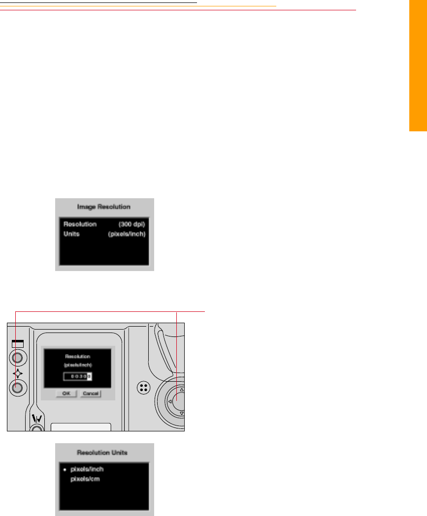
4-5
4
Configuring
Setting File Resolution
You can specify a file resolution to be saved in the header of subsequently captured
images. This property does not affect image processing in the camera, the DCS Acquire
Module, or the DCS TWAIN Data Source. The specified resolution is used by applications
such as Photoshop when displaying the images.
1Select the Menu icon, then
choose Properties from the
dropdown menu. Refer to
“Navigation Techniques” on
page 2-14.
2Select Resolution from the
Properties menu.
The Image Resolution screen
appears.
3Select Resolution or Units.
If you select Resolution, the
Resolution screen appears.
4Press and hold the Selector
button and press the left or right
side of the Navigate switch to
highlight the desired field.
5Press and hold the Selector
button and press the top or
bottom of the Navigate switch to
change the highlighted field.
If you select Units, the
Resolution Units screen
appears.
6Select Pixels/inch or Pixels/cm.
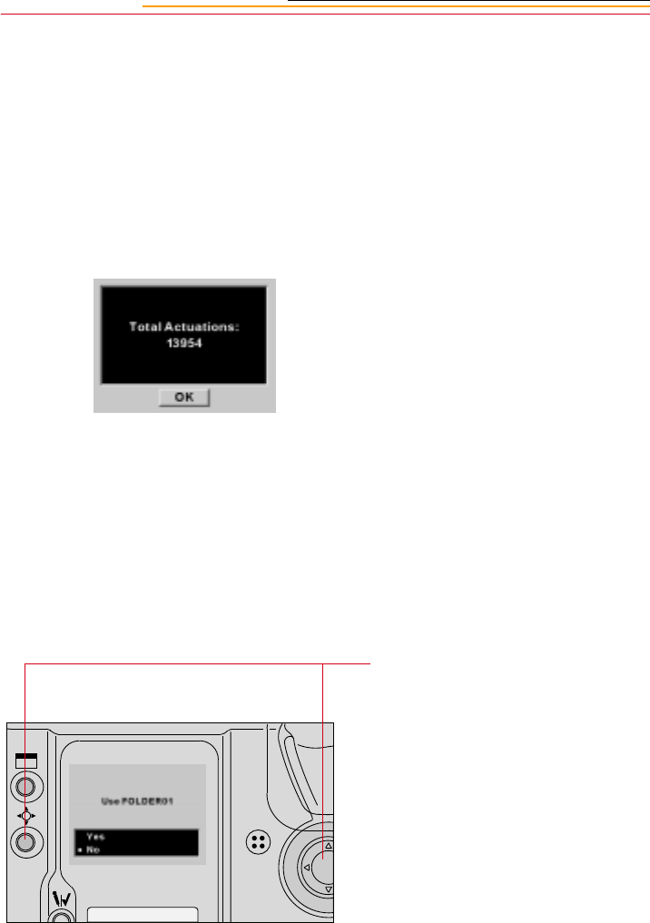
4-6
Determining Total Actuations
You can determine the number of images captured by your camera from the time of its
manufacture.
Use Folder 1
You can specify whether the default place to store images is an empty folder or folder 1
when you insert a new PC Card.
1Select the Menu icon, then
choose Properties from the
dropdown menu. Refer to
“Navigation Techniques” on
page 2-14.
2Select Total Actuations from the
Properties menu.
The Total Actuations screen
appears, informing you of the
number of images captured.
1With the Properties menu
displayed, select Use
FOLDER01.
This Use Folder 1 screen
appears.
2 Highlight Yes or No.
If you select Yes, every time you
replace your PC Card, images
will be stored in folder 1.
If you select No, every time you
replace your PC Card, images
will be stored in the first empty
folder found on the PC Card.

4-7
4
Configuring
Custom Settings
You can set Custom Settings using the Custom Settings menu (described below) or the
button (page 4-7). In general, the method described below is easier to use, since
the settings are labeled.
1Select the Menu icon, then
choose Custom Settings from
the dropdown menu. Refer to
“Navigation Techniques” on
page 2-14.
2Select the desired Custom
Setting.
The selected Custom Setting
screen appears.
3Select the desired setting.
CSM
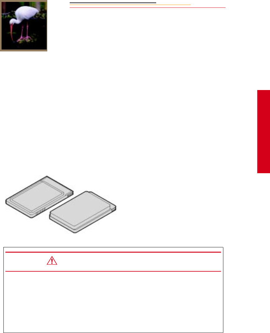
INSERT
PHOTO
HERE
5
PC Card
5-1
Using a PC Card
5
As you capture images, they are stored on a PC Card (PCMCIA card). Before capturing
images, you may want to make a few preparations so that the images will be stored
according to your needs. This chapter describes the use of the PC Card and provides
instructions for storing images.
PC Cards
Your camera accepts Type I, Type II, or Type III PC Cards which are compatible with the
PCMCIA-ATA interface standard. Most hard disk drive and flash memory cards may be
used. Hard disk drive cards will hold more images and are usually faster than flash
memory cards, but flash memory cards are more rugged.
☛PC Cards must be ATA-compatible.
CAUTIONS:
Use extreme care when handling PC Cards, as they are easily damaged. If
dropped, a PC Card may be destroyed, resulting in the loss of all data on the card.
Do not remove a PC Card from the camera while the Card Present icon on the
Back Status LCD panel or the Card Busy LED inside the Battery/PC Card door is
blinking. The blinking indicates that data is being read from or written to the PC
Card. You may lose data if you remove a card at this time.
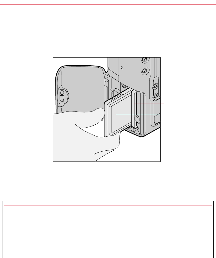
5-2
Dual Slots for PC Cards
Your camera has two PC Card slots. With Type II PC Cards, you can use one or both slots.
With Type III PC Cards, only one slot can be used. The card in the slot closest to the
camera back is referred to as CARD0, and the card in the slot closest to the camera front is
referred to as CARD1.
With one card, you can insert a PC Card in either slot. With two cards, the first card
inserted will be the active card. When you capture or delete images, they will be saved to
or deleted from the active card.
IMPORTANT:
Your camera uses 3 volt or 5 volt PC Cards. When you use two cards, they must both
have the same voltage rating. If you insert two cards with different voltages, neither is
powered. A “Card Voltage Mix” message appears. You need to remove one of the cards
so that the other can be powered.
CARD0
CARD1
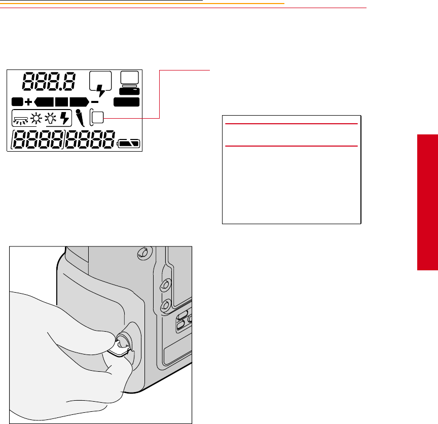
5-3
5
PC Card
Inserting/Removing PC Cards
It is not necessary to turn off the camera before inserting or removing a card.
1Check the Card Present icon on
the Back Status LCD panel. It
blinks when a card is busy.
2Lift the latch assembly on the
Battery/PC Card door and turn it
counter-clockwise to open the
door.
REAR
SLOW
AUTO
ISO
BKT CUSTOM
IMPORTANT:
If the Card Present icon is
blinking, wait until it stops
before continuing. (You can lose
data if you remove the PC Card
while it is busy.)
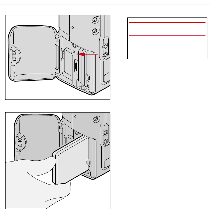
5-4
3To insert a PC Card: slide it all
of the way into the card slot and
press firmly.
☛A label inside the door
indicates the proper position
for the card.
IMPORTANT:
Be sure that the Card Busy LED
is Off before continuing.
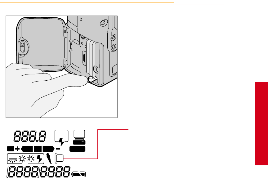
5-5
5
PC Card
4To remove a PC Card, press the
Eject button and pull the card
out.
5Close the Battery/PC Card door.
The Card Present icon is
displayed on the Back Status
LCD panel when there is a PC
Card in the camera.
REAR
SLOW
AUTO
ISO
BKT CUSTOM
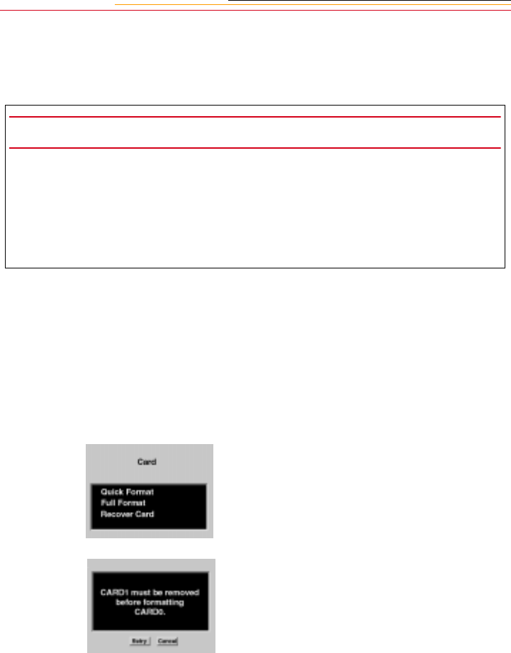
5-6
Formatting a PC Card
To prevent formatting the wrong PC Card, there can only be one card in the camera when
you format a card. Format the card using either the quick format or the full format feature.
IMPORTANT:
Quick format, while faster, is not recommended if there is a possibility that there are
defects on the PC Card.
The Recover function only works if a PC Card has been formatted on the camera. Refer
to “Recovering Deleted Images” on page 12-15. (If you format a card using the DCS
Host Software, the Recover function will not work.)
1Select the Menu icon, then
choose Main Menu from the
dropdown menu. Refer to
“Navigation Techniques” on
page 2-14.
2Select Card from the Main
menu.
The Card menu appears.
3Choose Quick Format or Full
Format.
If two cards are in the camera,
you are prompted to remove the
inactive card. For example, if
CARD0 is active, you are
prompted to remove CARD1.
4Remove the inactive card, then
select Retry.

5-7
5
PC Card
If you remove the active card,
the message at the left appears.
5Re-insert the card in the proper
slot, then select Retry.
A confirmation screen appears.
6Select Yes or No.
If you choose No, the Main
menu appears and the card is not
formatted.
If you choose Yes, the card is
formatted. A Progress screen
appears.
If you wait for the progress bar
to go to completion, a full
format occurs. If you press the
Cancel button, a quick format
occurs. With a quick format, the
card will be usable, but
occasional errors may occur
when you save images.
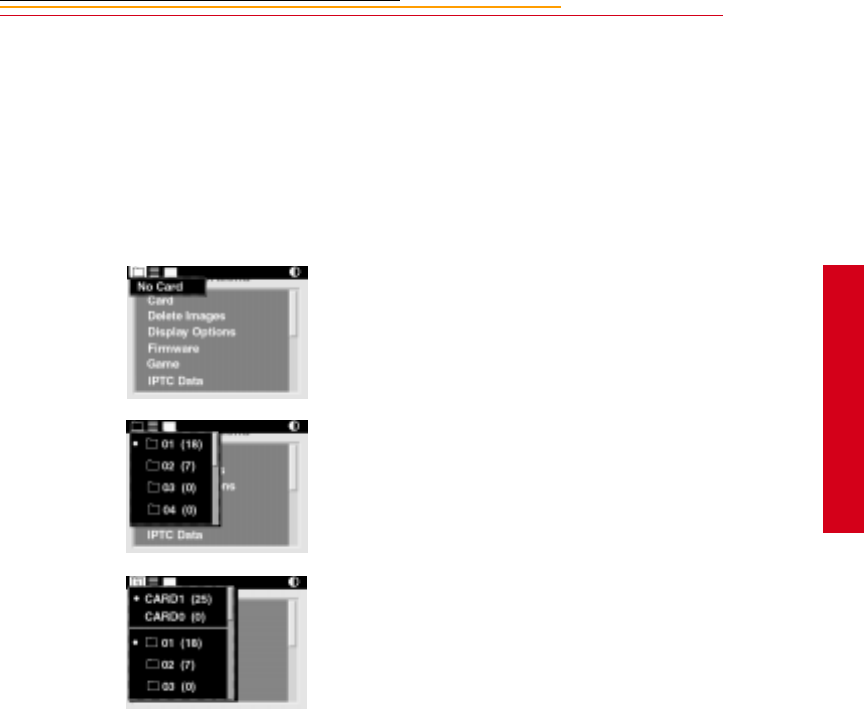
5-8
5
PC Card
Selecting a PC Card or Folder
Images are stored in folders on a PC Card. There is always at least one empty folder on
your PC Card. When you store an image in an empty folder, a new empty folder is
automatically created. The new folder is called FolderX, (X being the next number
available).
1Select the Folder icon. Refer to
“Navigation Techniques” on
page 2-14.
If there is no PC card in the
camera, an X appears within the
Folder icon. Selecting the icon
produces a menu stating No
Card.
With one PC Card inserted, this
dropdown menu appears with a •
displayed next to the currently
active folder.
With two PC Cards inserted, this
dropdown menu appears with •
displayed next to the currently
active card and folder.
A 0 or 1 appears in the Folder
icon, indicating the active card.
The listed folders are on the
active card. The folder list
changes when you change cards.
The numbers in parentheses next
to the cards and folders indicate
the number of images in each.
2With two PC Cards inserted,
select CARD0 or CARD1, then
select a folder. With one card
inserted, select a folder.
x

6
Saving Files
6-1
Saving Files
6
JPEG and TIFF File Processing
The DCS 620 and 620x cameras support background image processing that produces
JPEG or TIFF RGB files that can be opened directly by any image editing software. This
feature is not available on the DCS 660 or 660M cameras.
The choices for processed files are JPEG Good, Better, Best, and TIFF RGB. JPEG Good
files have the most compression, JPEG Best have the least. The less compression, the
better the quality of the processed file and the larger the file size. The file size varies,
depending on content. TIFF RGB files are not compressed.
When you capture images, they are written to the selected folder using the TIFF Custom
format, regardless of whether processing is turned on. If you turn on processing, JPEG
Best, Better, Good, or TIFF RGB files are created and saved when the camera is not busy
with other tasks such as capturing images.
JPEG files are saved to a JPEG folder and TIFF RGB files are saved to a TIFF folder.
These folders are created on the PC Card when you turn processing on (if they don’t
already exist). If you select the JPEG or TIFF folder to review images, then you capture an
image, a message informs you that images cannot be saved there. The images are saved in
the default folder established in Properties. You can specify whether the original TIFF file
is saved or deleted once the JPEG or TIFF RGB file is saved.
Processing is turned off by default. When you turn on processing, it stays on until you turn
it off, or remove the PC Card.
Processing with Two PC Cards
When you have PC Cards in both slots, images are processed on the card that is active
when you turn on processing. If you make the other card active, processing continues on
the inactive card. For example, if CARD0 is active when you turn on processing, then you
change to CARD1, processing continues on CARD0, but not on CARD1. In this case, if
you want to switch processing to CARD1, you must turn off processing, then turn it back
on. When turned on, processing will automatically be set for the active card (CARD1).
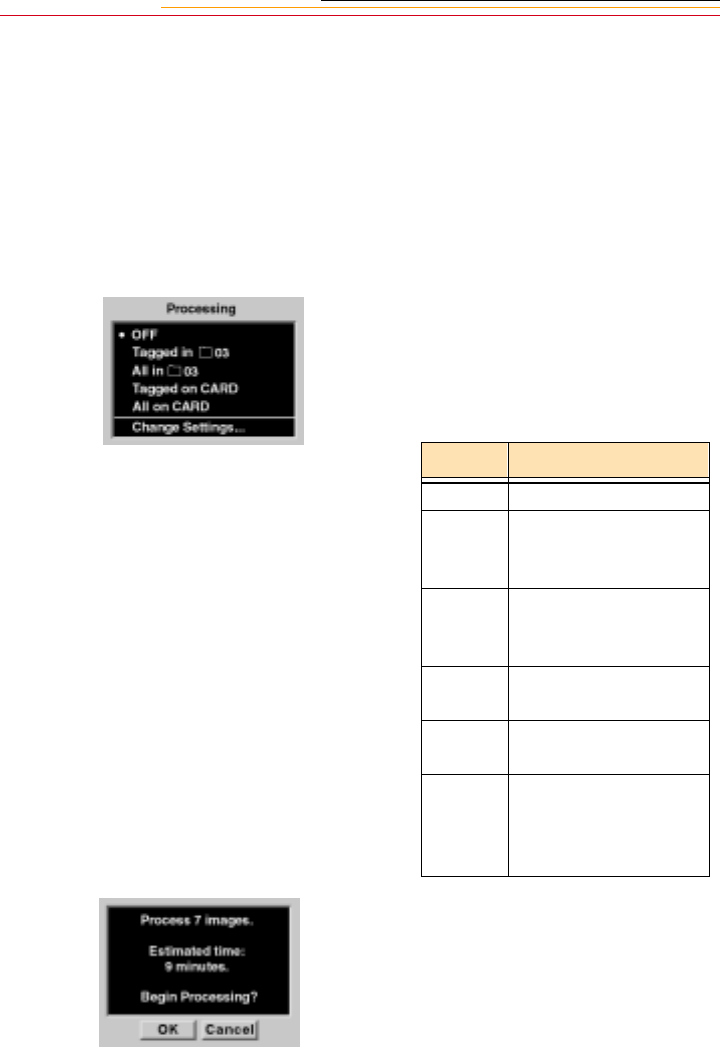
6-2
Processing Images
1Select the Menu icon, then
choose Main Menu from the
dropdown menu. Refer to
“Navigation Techniques” on
page 2-14.
2Select Processing from the Main
menu.
The Processing menu appears. If
two PC Cards are inserted, the
active card is indicated (for
example, All on CARD1).
3Select your choice.
The Processing confirmation
screen appears.
4Select OK to begin processing
or Cancel to return to the Main
menu without processing.
Choice Images Processed
OFF Turns off Processing
Tagged
in folder
All tagged images in
the selected folder on
the active card
All in
Folder All images in the
selected folder on the
active card
Tagged
Images
All tagged images on
the active card
All on
Card
All images on the
active card
Change
Settings Displays a screen
where you can change
Processing settings
(page 6-5)
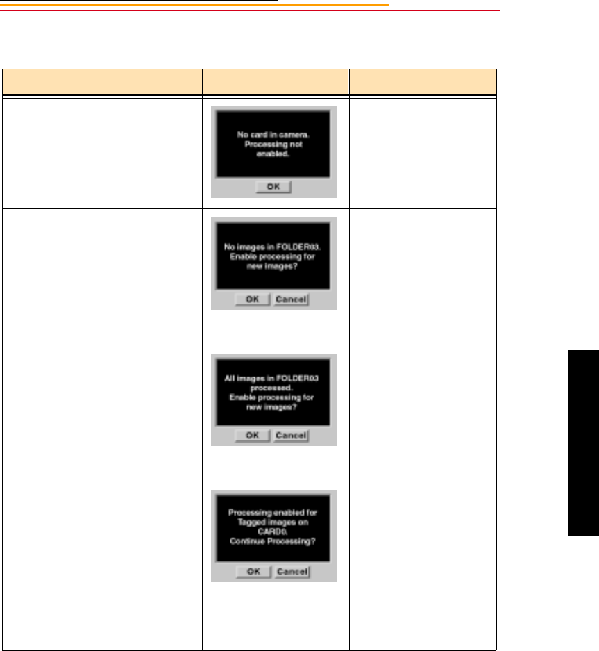
6-3
6
Saving Files
When you enable processing, certain conditions may exist which will cause other screens
to appear, as shown in the table below.
Condition Screen Your Action
There is no PC Card in the
camera.
Click OK and insert a
PC Card.
Processing is enabled for the
selected folder and there are no
images in the folder.
Similar screens appear when the
same condition exists for tagged
images or for all images on the
card.
If you click OK, new
images are processed
when you capture them
to that folder.
If processing is enabled
for tagged images or all
images on the card, then
images are processed as
you tag or capture them.
If you click Cancel,
processing is not started.
Processing is enabled for the
selected folder and all images in
the folder have been processed.
Similar screens appear when the
same condition exists for tagged
images or for all images on the
card.
There are two PC Cards in the
camera. With processing enabled
for one card, you make the other
card active, then access the
Processing menu.
If you click OK,
processing continues on
the inactive card.
If you click Cancel,
processing stops on the
inactive card. You can
then enable processing
on the active card, if
desired, if desired.
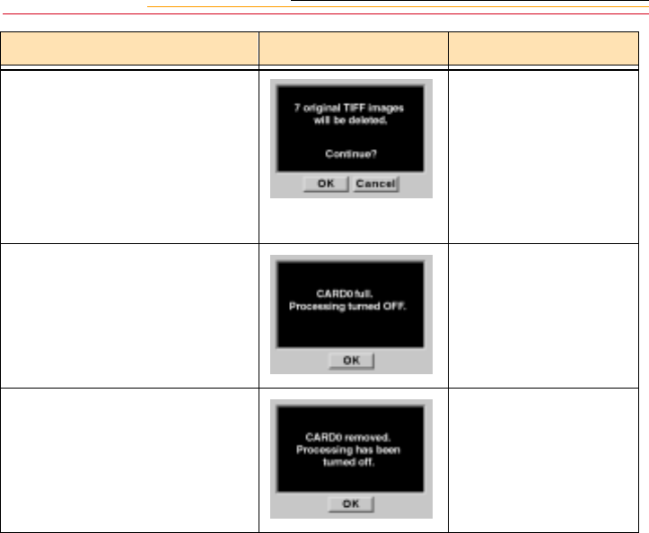
6-4
Your processing settings are set to
delete the original TIFF image
when you process files. Refer to
“Changing Processing Settings”
on page 6-5.
If you click OK, a
second confirmation
screen appears.
If you click Cancel,
processing is not started.
The Processing menu
appears.
The active PC Card becomes full
as images are being processed.
This can occur regardless of
whether there are one or two cards
in the camera.
Click OK and delete
some images or insert a
different card.
You remove a PC Card while
processing is enabled (whether or
not images are currently being
processed).
Condition Screen Your Action
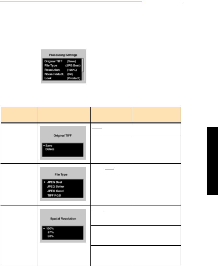
6-5
6
Saving Files
Changing Processing Settings
There are several processing settings that you can change. The settings are applied to
images as they are processed.
1Select Change Settings from the
Processing menu.
The Processing Settings menu
appears with the current values
shown in parentheses.
2Select the desired setting.
The following screens appear,
depending on your choice:
Processing
Settings Screen Defaults
Underlined Result
Original TIFF Save Saves the TIFF image
(default).
Delete Deletes the TIFF
image after the
processed JPEG file
has been saved.
File Type JPEG Best, Better,
Good, TIFF RGB
Files are processed to
the selected JPEG
quality.
Resolution 100% Maintains the size and
spatial resolution of
the original image.
67% The size and spatial
resolution are reduced
to two-thirds.
50% The size and spatial
resolution are reduced
to one-half.
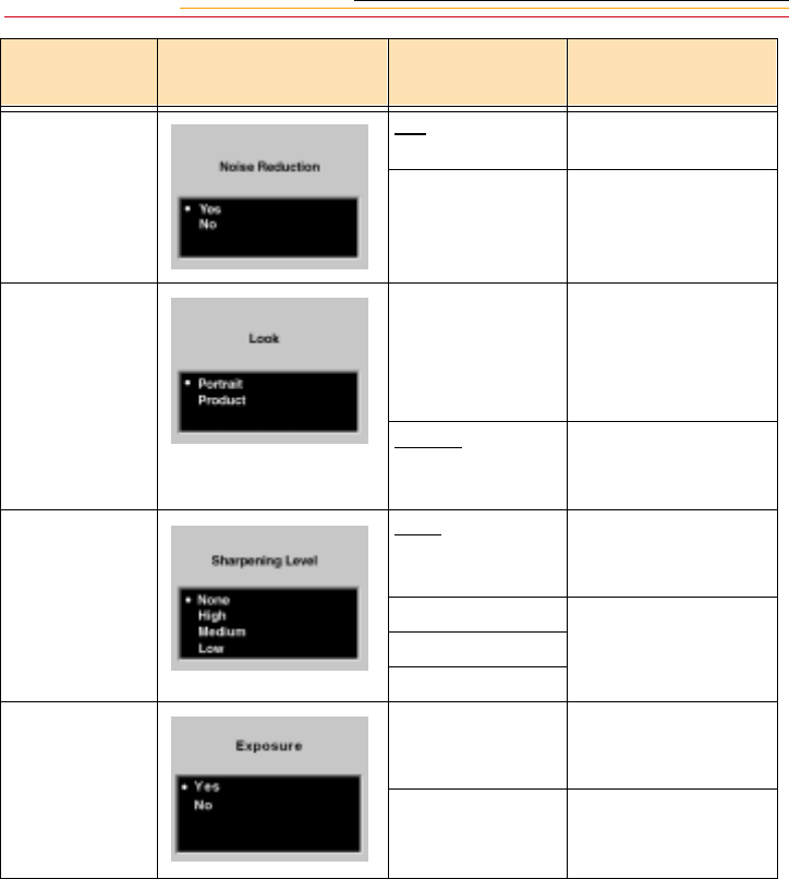
6-6
* The Sharpening Level setting in the Processing menu determines whether sharpening is
applied when images are processed on the camera. The Sharpening property in the
Properties menu determines whether sharpening is applied by the DCS Host software.
Refer to “Enabling Sharpening” on page 4-4.
Noise
Reduction
Yes Noise is reduced in
processed images.
No Noise is not reduced.
Look Portrait Applies a lower
contrast tone scale
with more detail in the
highlights and
shadows.
Product Applies a higher
contrast, more vibrant
tone scale.
Sharpening
Level *
None No sharpening is
applied to the finished
image.
High Progressively less
sharpening is applied
to the finished image.
Medium
Low
Exposure Yes Automatic exposure
compensation is
applied
No Automatic exposure
compensation is not
applied
Processing
Settings Screen Defaults
Underlined Result

6-7
6
Saving Files
Working with TIFF Custom Files on your Computer
If you don’t process images on your camera, you need to use one of the following software
applications to work with the TIFF Custom files. (The TIFF Custom file format is
proprietary to Kodak.)
File Format Module
✔This software application allows you to open high resolution TIFF Custom images
directly into Photoshop.
DCS Acquire Module or DCS TWAIN Data Source
✔These are full-featured image editing and acquire software applications.
If the DCS Host Software CD (included with your camera) includes the DCS Acquire
Module and DCS TWAIN Data Source version 5.8 or later, you will be given the option of
installing the DCS File Format Module. If the CD includes a version prior to 5.8, the DCS
File Format Module is not included. To download the DCS File Format Module, visit the
Kodak Web site (www.Kodak.com).
☛If you attempt to open TIFF Custom files in Photoshop without using the DCS File
Format Module, the DCS Acquire Module, or DCS TWAIN Data Source, only the
thumbnail version is available, yielding a less than optimal image resolution.
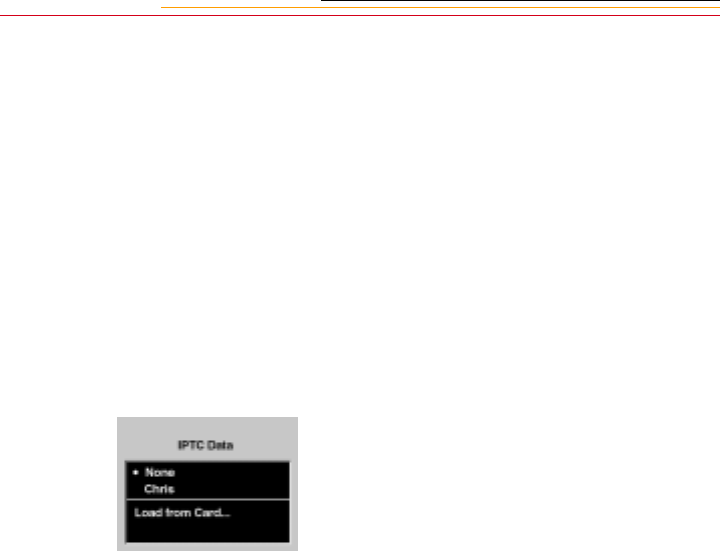
6-8
IPTC Data Management
This feature allows inclusion of International Press Telecommunication Council (IPTC)
data as part of the image header. You enter the IPTC data on your computer using the DCS
Acquire Module or DCS TWAIN Data Source (version 5.8 or later) and save it to a PC
Card. (Refer to the KODAK PROFESSIONAL DCS Host Software User’s Manual.)
Once IPTC data has been saved to a PC Card, you can load the data into your camera
(page 6-9).
1Select the Menu icon, then
choose IPTC Data from the
dropdown menu. Refer to
“Navigation Techniques” on
page 2-14.
2Select your choice from the
IPTC Data menu:
None—No IPTC data will be
written to the image headers.
IPTC Data File—If there is an
IPTC file on the camera, it is
displayed. Choosing this option
writes the IPTC data to the
image header.
Load from Card—You can
load an IPTC file from a PC
Card. Refer to “Loading IPTC
Data from a PC Card” on page
6-9.
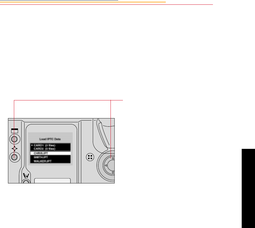
6-9
6
Saving Files
Loading IPTC Data from a PC Card
1With the Load IPTC Data screen
displayed (page 6-8), choose
Load from Card.
The Load IPTC Data screen
appears with a list of the IPTC
files on the active PC Card. (If
only one card is in the camera,
the card choices do not appear.)
2Press and hold the Selector
button and use the Navigate
switch to choose the desired
card. (You may need to scroll up
to the card choices if there are
numerous IPTC files.)
3Repeat step 2 to choose an IPTC
file.
The file is loaded from the PC
Card to your camera.
Each file must have a unique
name. If you attempt to load a
file with the same name as one
on your camera, a message asks
if you want to replace the
existing file.
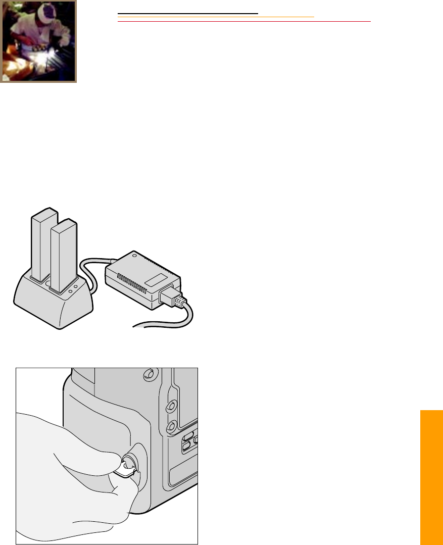
INSERT
PHOTO
HERE
7
Quick Start
7-1
Quick Start
7
This chapter contains information that enables you to start using your camera. Much of the
information in this chapter can be found in greater detail in other areas of the manual.
Before You Start
1If you have not already done so,
charge your battery using the
external battery charger that was
included with your camera.
You can insert either one or two
batteries in the battery charger
(either slot). The light on the
battery charger turns green when
the batteries are completely
charged. Refer to “Charging
Batteries” on page 3-8.
2Turn off the camera.
3Lift the latch assembly on the
Battery/PC Card door and turn it
counter clockwise to open the
door.
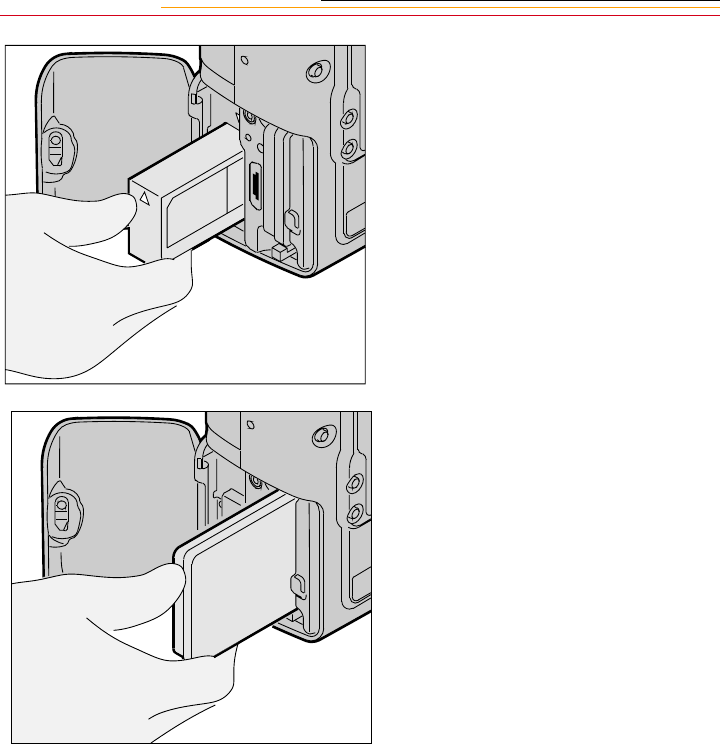
7-2
4Insert the battery into the battery
slot.
5Insert a PC Card into the card
slot.
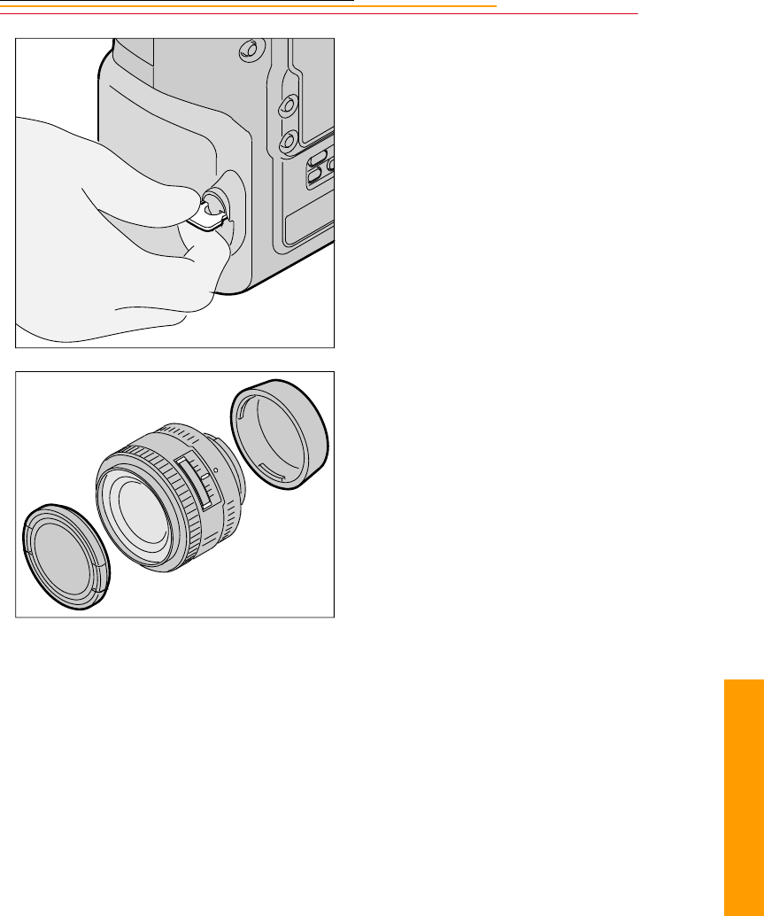
7-3
7
Quick Start
6Turn the latch assembly
clockwise to close the
Battery/PC Card door.
7Remove the camera body cap
and the front and rear lens caps.
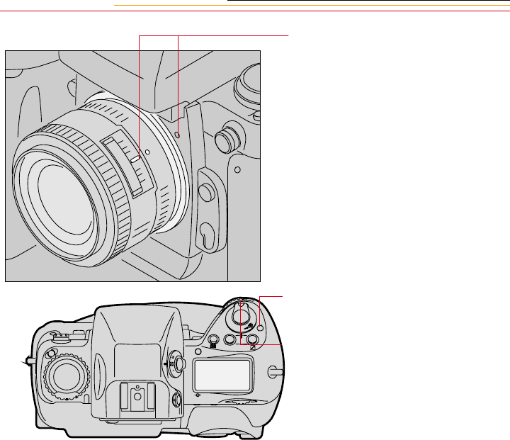
7-4
8Position the lens in the camera’s
bayonet mount so that the
mounting indexes on the lens
and camera body are aligned.
Taking care not to press the Lens
Release button, twist the lens
counter clockwise until it locks
in place.
9Press the Power Switch Lock
release.
10 Rotate the Power switch
clockwise to turn on the camera.
C
S
L
MODE
O
O
F
N
F
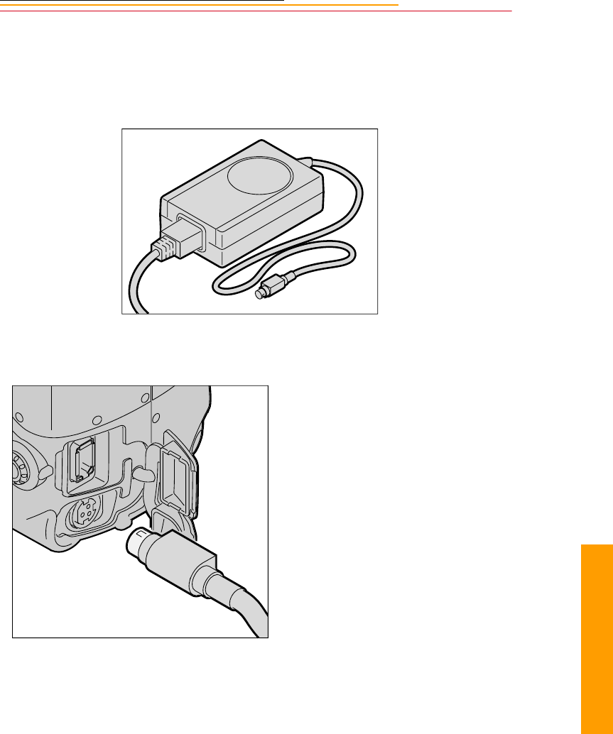
7-5
7
Quick Start
The AC Adapter for Camera
Conserve your battery and power your camera by using the AC adapter for camera,
whenever possible. Refer to “AC Adapter for Camera” on page 3-13.
Connecting the AC Adapter for Camera
1Open the connector cover at the
side of the camera.
2Plug the AC adapter into the AC
Adapter connection.
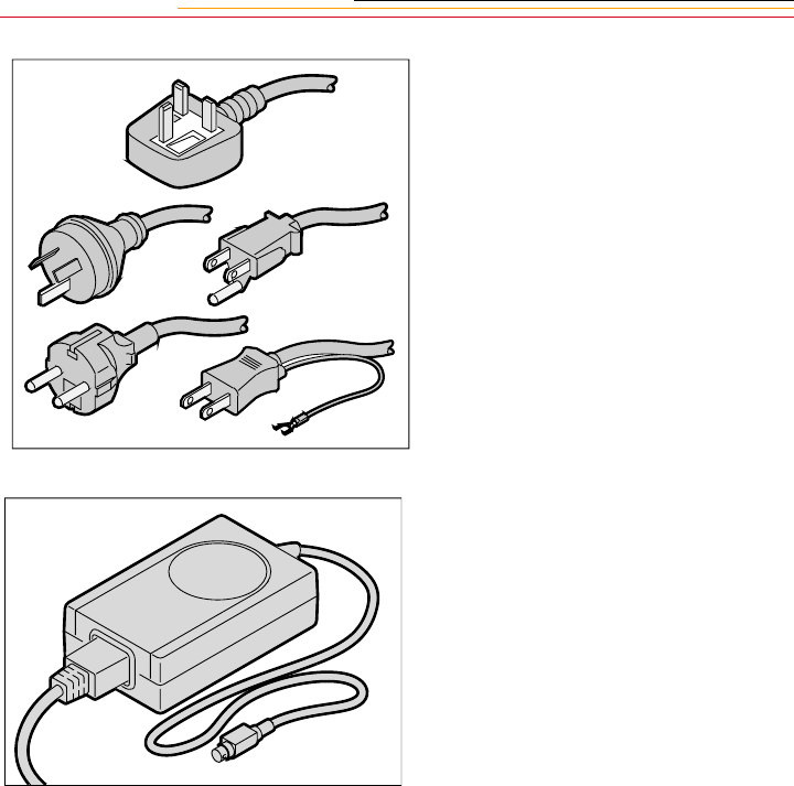
7-6
3Select the power cord with
universal plug that is appropriate
for your area.
4Plug the appropriate end of the
power cord into the AC adapter
for camera.
5Plug the power cord into a wall
outlet.
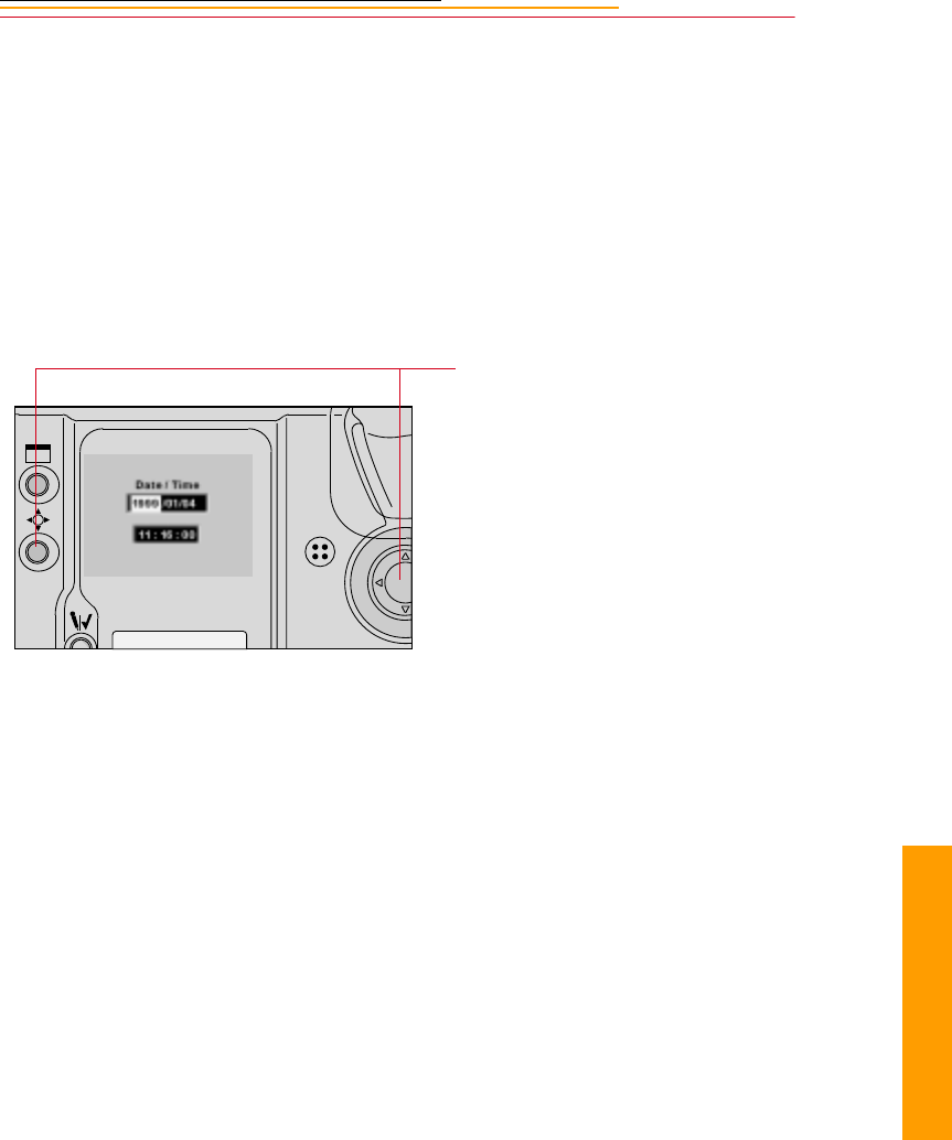
7-7
7
Quick Start
Optional Settings Before You Start
Set the Date and Time
Select a PC Card or Folder
Before capturing images, you should specify a PC Card and folder for storing images.
Refer to “Selecting a PC Card or Folder” on page 5-8.
1Select the Menu icon, then
choose Main Menu from the
dropdown menu (page 2-14).
2Select Date/Time from the Main
menu.
The Date/Time screen appears.
3Press and hold the Selector
button and press the left or right
side of the Navigate switch to
highlight the desired field.
4Press and hold the Selector
button and press the top or
bottom of the Navigate switch to
change the highlighted field.
5Repeat for all fields on the
Date/Time screen.
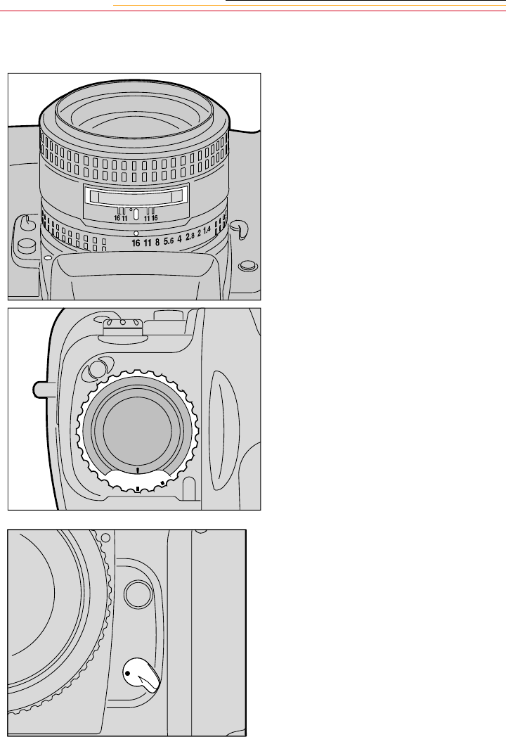
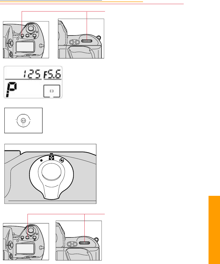
7-9
7
Quick Start
4Press and hold the AF Area
Mode button and rotate the
Main-Command dial to select
Single Area AF mode.
The selected focus area of the
Top Status LCD panel displays
only [ ].
The Focus bracket also appears
in the viewfinder.
5While pressing the lock release,
set the Metering System selector
for 3D Color Matrix Metering.
6Press and hold the Exposure
mode (MODE) button and
rotate the Main-Command dial
to select Programmed Auto
Exposure mode.
F
N
F
O
O
MODE
AF-ON
AF-L
AE-L
F
N
F
O
O
MODE
AF-ON
AF-L
AE-L
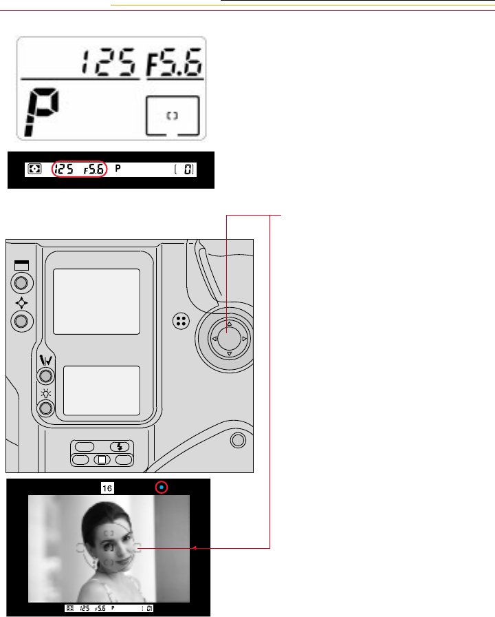
7-10
P appears in the Top Status LCD
panel and viewfinder.
7Press the Navigate switch to
position the focus brackets on
your main subject.
ISO
BKT CSM
L
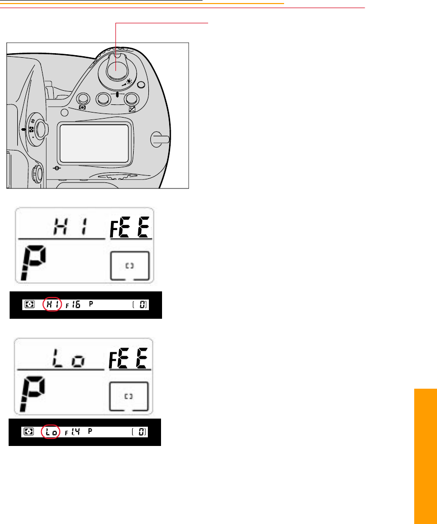
7-11
7
Quick Start
8Lightly press the Shutter
Release button.
☛If HI appears in the shutter
speed position—Over-
exposure alert: Use a NIKON
ND filter.
☛If Lo appears in the shutter
speed position—Under-
exposure alert: Use an
accessory NIKON Speedlight.
F
N
F
O
O
MODE
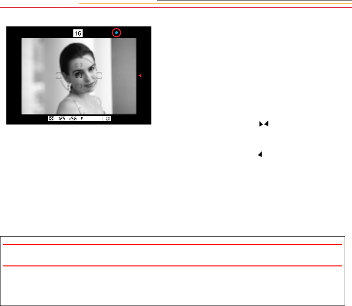
7-12
9Confirm that a green “•” appears
inside the viewfinder (indicating
successful focusing), then fully
depress the Shutter Release
button to capture the image.
The Shutter cannot be released in
the following situations:
✔When blinks: Focus
manually.
✔When appears: Subject is
too close. Move away from
your subject.
To conserve battery power, turn off
the camera when it is not in use.
CAUTION:
Always remove batteries before storing your camera to prevent damage due to
leaking batteries.
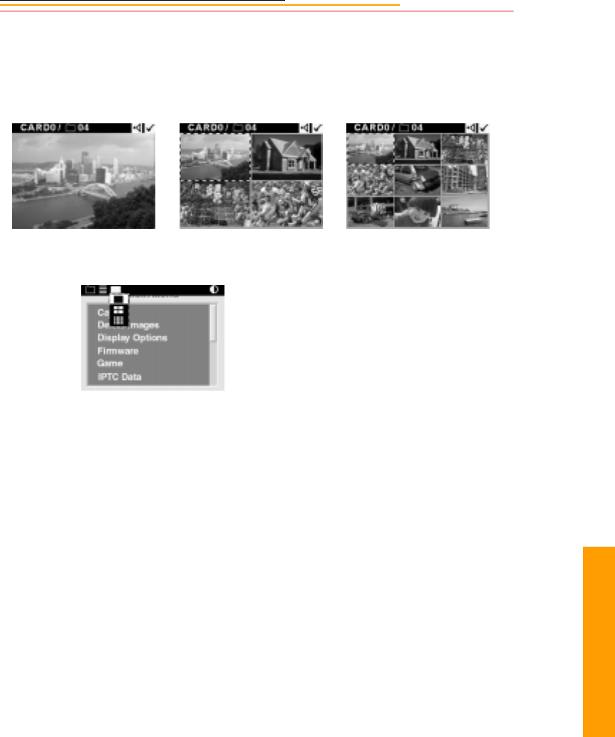
7-13
7
Quick Start
Reviewing Images on Your Camera
You can display one, four or nine images on the Image LCD panel.
Single Image Review mode Four Image Review mode Nine Image Review mode
1Select the Display icon, then
choose Single, Four, or Nine
Image Review mode from the
dropdown menu (page 2-14).
2Press and hold the Selector
button and press the right or left
side of the Navigate switch to
navigate through the images
horizontally, or press the top or
bottom to navigate vertically.
3Release the Selector button to
select an image.
☛ You need to select an image to
tag it, view information about
it, or associate a sound file
with it as described on
subsequent pages.
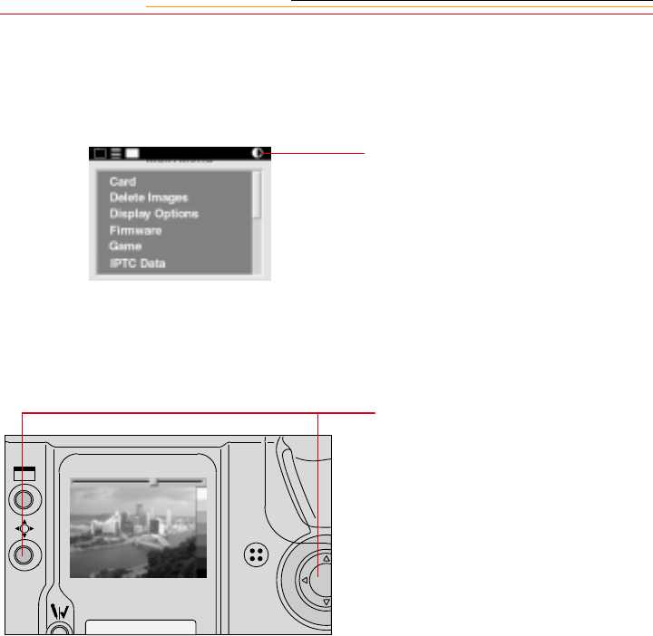
7-14
Setting Display Contrast
You can change the contrast to lighten or darken the images displayed on the Image LCD
panel.
Select the Contrast icon. Refer to
“Menu Bar” on page 2-12.
A grayscale bar is displayed at
the side of the image and a
slider is displayed across the
top.
4Press and hold the Selector
button and press the right or left
side of the Navigate switch to
move the slider. Continue until
you achieve the desired contrast.
The displayed image changes to
reflect the contrast adjustment,
as does the grayscale bar.
☛With proper contrast, the
grayscale bar will run from
black to white, with clearly
defined steps in between.
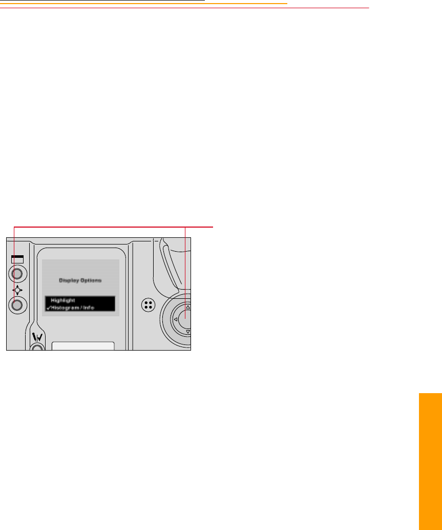
7-15
7
Quick Start
Setting Display Options
You can view areas of overexposure, an exposure histogram, and information about the
selected image.
1Select the Menu icon, then
choose Main Menu from the
dropdown menu. Refer to
“Navigation Techniques” on
page 2-14.
2Select Display Options from the
Main menu.
The Display Options screen
appears. A checkmark next to
an option indicates that it is on.
3Press and hold the Selector
button and use the Navigate
switch to turn an option On or
Off.
If you turn on Highlighting, any
overexposed areas of the image
will blink.
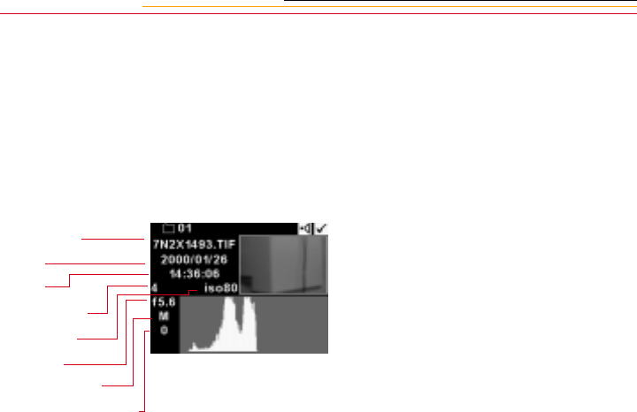
7-16
If you turn the Histogram/Info
option on while in single image
review mode, the Histogram and
exposure info will appear.
☛The information will not be
displayed In Four or Nine
Image Review mode.
The image histogram shows the
range and distribution of tonal
values for an image. It displays
the number of occurrences of
each pixel code value, and can
be used to assess an image’s
brightness and contrast levels.
Pixel code values represent the
relative value of light intensities
in a scene. They range from 0
(darkest elements in a scene) to
255 (brightest elements in a
scene). For a high contrast
image, the histogram includes
almost the entire range of pixel
code values. For a low contrast
image, the histogram includes a
small range of pixel code values.
If you toggle the Selector
button, you can alternate
between the full frame image
view and the Histogram/Info
view.
Image name
Date
Time
Shutter speed
ISO setting
Aperture
Exposure mode
Exposure compensation
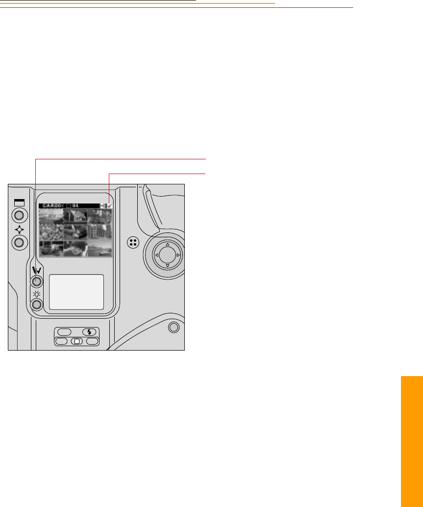
7-17
7
Quick Start
Tagging Images
You can tag images to be processed (page 6-2) or NOT to be deleted (page 7-19). Images
retain their tags when acquired using the DCS Host software where you can select tagged
or untagged images and perform a variety of operations. Refer to the KODAK
PROFESSIONAL DCS Host Software User’s Manual on the DCS Host Software CD
included with your camera.
1Select the desired review mode.
Refer to “Setting the Review
Mode” on page 12-2.
2Select an image.
3Press the Record/Tag button.
A Tag icon appears at the right
of the Menu Bar.
☛To tag the last image captured,
press the Record/Tag button.
This will work until the
camera enters PowerSave
mode or you perform another
operation.
ISO
BKT CSM
L
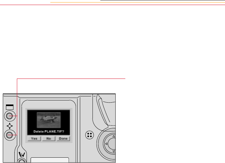
7-18
Deleting Images
You can delete one or more images from a PC Card in your camera. When you do so, any
associated sound files are also deleted. Refer to “Associating a Sound File with an Image”
on page 7-20.
Deleting a Single Image
1Press and hold the Display
button and the Selector button at
the same time.
If the Image LCD panel is off, it
will turn on.
The Delete Image screen
appears showing the current
image (whether the Image LCD
panel was on or off).
2Release the Display button.
3While continuing to hold the
Selector button, use the
Navigate switch to highlight
Yes, No, or Done in response to
the “Delete this image?”
prompt.
If you choose Yes, the current
image is deleted and the next
image appears in the screen.
If you choose No, the current
image is not deleted and the next
image appears in the screen.
If you choose Done, the current
image is not deleted and the
screen goes away.

7-19
7
Quick Start
Deleting More Than One Image
You can delete all images on the PC Card, all images in a folder, all untagged images on
the PC Card, or all untagged images in a folder.
1To delete untagged images
(described below), tag any
images that you DO NOT want to
delete.
2Select the Menu icon then
choose Main Menu. Refer to
“Navigation Techniques” on
page 2-14.
3Select Delete Images from the
Main menu.
The Delete Images menu
appears.
4Select the desired option, then
respond to the confirmation
screen.
☛Remember that if you choose
“Untagged in FOLDERx” or
“Untagged on Card”, images
that you have tagged are NOT
deleted.
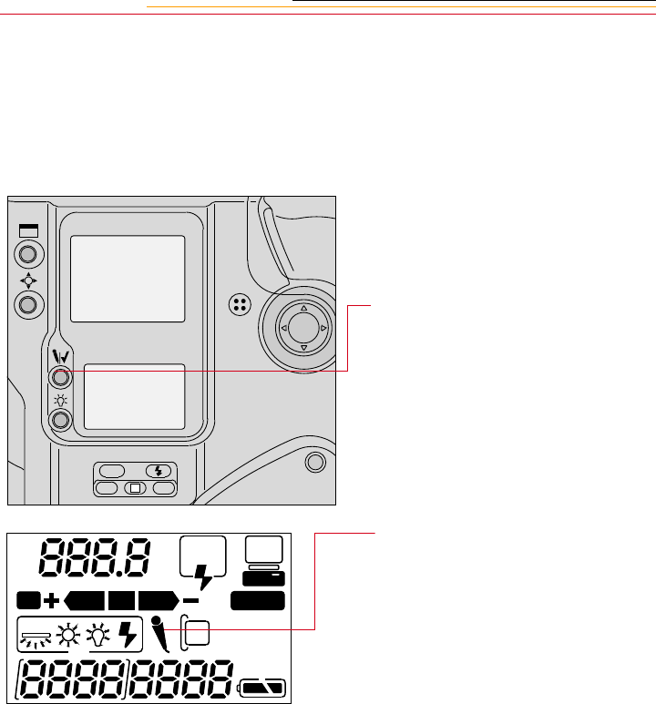
7-20
Associating a Sound File with an Image
You can record sound files for your images, then play back the sound files using the DCS
Host software (if your computer has a sound board). Refer to the KODAK
PROFESSIONAL DCS Host Software User’s Manual on the DCS Host Software CD
included with your camera.
A Microphone icon appears in
the Back Status LCD Panel
indicating that you can begin
recording.
ISO
BKT CSM
L
1Select the image to which you
wish to associate a sound file.
Refer to “Selecting an Image”
on page 12-7.
2Press and hold the Record/Tag
button.
REAR
SLOW
AUTO
ISO
BKT CUSTOM
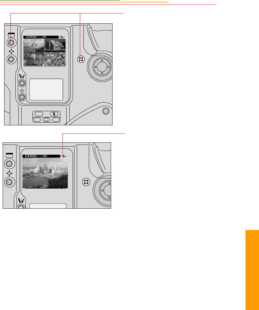
7-21
7
Quick Start
You cannot record sounds and the Microphone icon is not displayed in the Back Status
LCD panel under the following circumstances:
✔No image is in the current folder
✔No PC Card is in the camera
✔The PC Card in the camera is full
✔You are capturing an image
3Speak into the microphone
while continuing to press and
hold the Record/Tag button.
4Release the Record/Tag button.
Recording stops and the
Microphone icon disappears
from the Back Status LCD panel.
A Sound icon appears in the
Menu bar, indicating that the
currently selected image has one
or more associated sound files.
ISO
BKT CSM
L

INSERT
PHOTO
HERE
8
Exposure
8-1
Controlling
Exposure
8
This chapter describes the functions available for controlling exposure in your camera.
White Balance
The DCS 620, 620x, and 660 cameras offer Custom White Balance functionality. (This
feature is not available with the DCS 660M camera.)
You can save White Balance settings using the your camera or the DCS Acquire Module
or DCS TWAIN Data Source (version 5.8 or later). You can also delete White Balance
settings when they are no longer needed.
This feature saves you time if you repetitively work under the same lighting conditions.
For example, if you frequently work in an indoor stadium with a particular type of
lighting, you can name and save a White Balance setting for reuse.
When you select a white balance option, you identify the type of lighting used to capture
an image. For example, if you capture an image in daylight, you would set the white
balance to daylight for the best results.
IMPORTANT:
White balance affects how your color image is captured. If you use an incorrect setting,
you may not get optimal results.
Be careful not to cover the white balance sensor window on the front of the camera
with the hand grip or your finger as this will affect auto white balance settings.
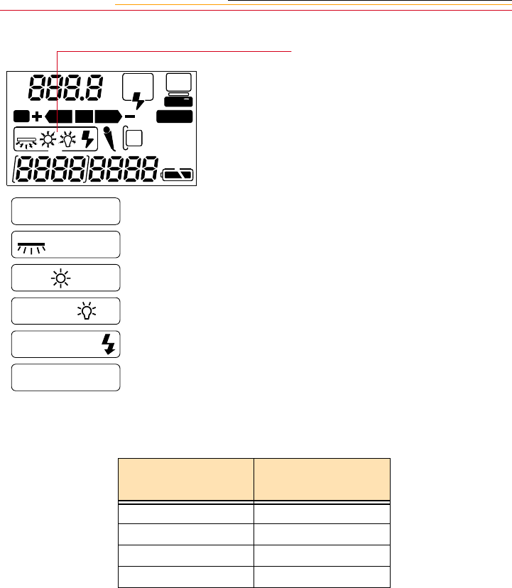
8-2
The table below shows the predicted color temperature at each White Balance setting:
To determine the current white
balance setting, check the White
Balance icons on the Back LCD
panel.
The icons reflect the current
setting.
If a flash is attached to your
camera and you choose Auto
mode, the Auto Flash icons
appear.
White Balance
Setting Color Temperature
(Degrees Kelvin)
Daylight 5500
Tungsten 3200
Fluorescent 5000
On-Camera Flash 5600
REAR
SLOW
AUTO
ISO
BKT CUSTOM
Auto - Flash
Daylight
Tungsten
Flourescent
Flash
AUTO
Custom

8-3
8
Exposure
Selecting Custom White Balance
You must select Custom White Balance before selecting, deleting, or loading Custom
White Balance settings.
Press and hold the White Balance
button and use the Navigate switch
until no White Balance icons appear
in the Back LCD panel.
When no icons appear, Custom
White Balance is selected.
ISO
BKT CSM
L
REAR
SLOW
AUTO
ISO
BKT CUSTOM
REAR
SLOW
AUTO
ISO
BKT CUSTOM
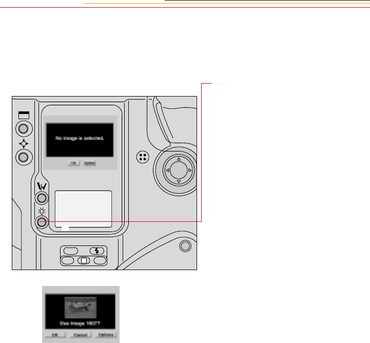
8-4
Using White Balance Settings
Once you have selected Custom White Balance, you can access several Custom White
Balance functions.
1Press the White Balance button.
If the Image Display was Off, it
turns On.
If there are no images in the
folder, this screen appears.
If the selected folder contains
images, this screen appears,
showing the currently selected
image.
2Select your choice:
OK—The White Balance values
from the selected image are
saved using the same name as
the image. The setting is applied
to subsequent images that you
capture. (This setting overwrites
the setting that was saved the
last time you chose OK.)
Cancel—The White Balance
setting does not change.
ISO
BKT CSM
L

8-5
8
Exposure
Options—The White Balance
Settings menu appears. You can:
✔Select a White Balance
setting from those loaded on
the camera (page 8-6)
✔Delete a White Balance
setting from the camera
(page 8-6)
✔Load a White Balance
setting from a PC Card to the
camera (page 8-7)
✔Save a White Balance setting
(page 8-9)
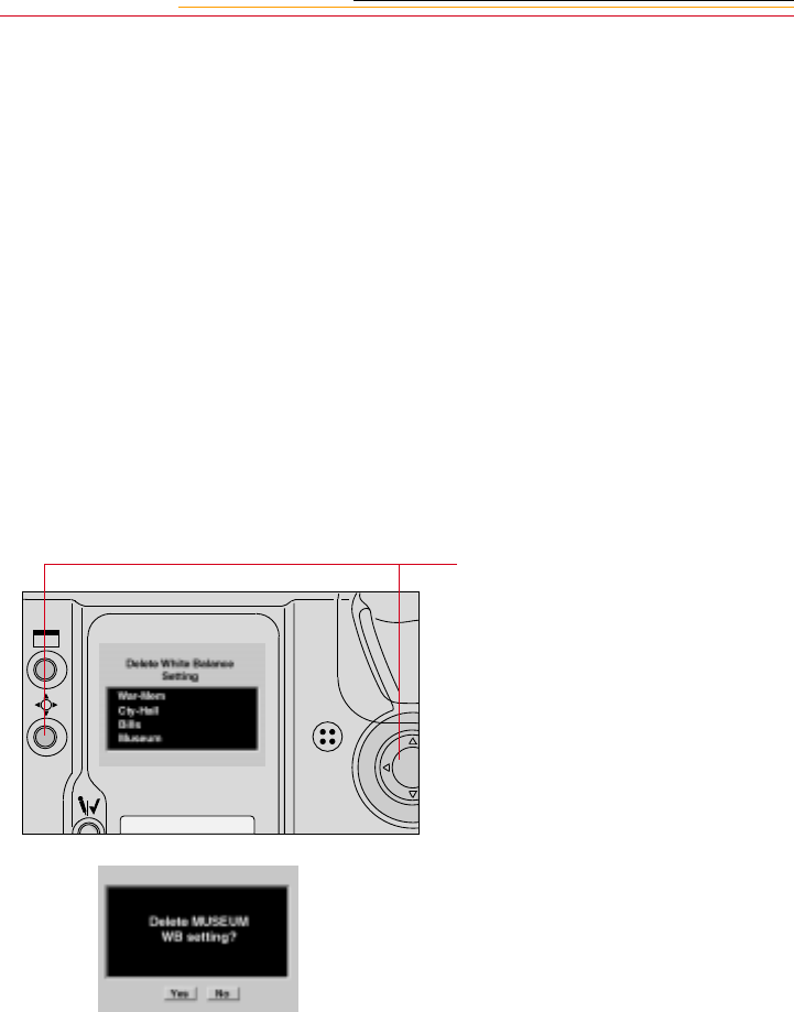
8-6
Selecting White Balance Settings
With the White Balance Settings menu displayed (page 8-4), choose one of the following:
Image #xxxx: The White Balance values from the selected image are applied to
images that you capture.
Previously loaded setting—The White Balance values from the previously loaded
setting (page 8-7) are applied to images that you capture.
Deleting White Balance Settings
You can delete White Balance Settings that have been loaded on your camera.
1With the White Balance Settings
menu displayed (page 8-4),
choose Delete WB Settings.
The Delete White Balance
Setting menu appears.
2Select the setting to be deleted.
Refer to “Navigation
Techniques” on page 2-14.
A confirmation screen appears.
3Select Yes to delete the setting,
or No to leave it intact.
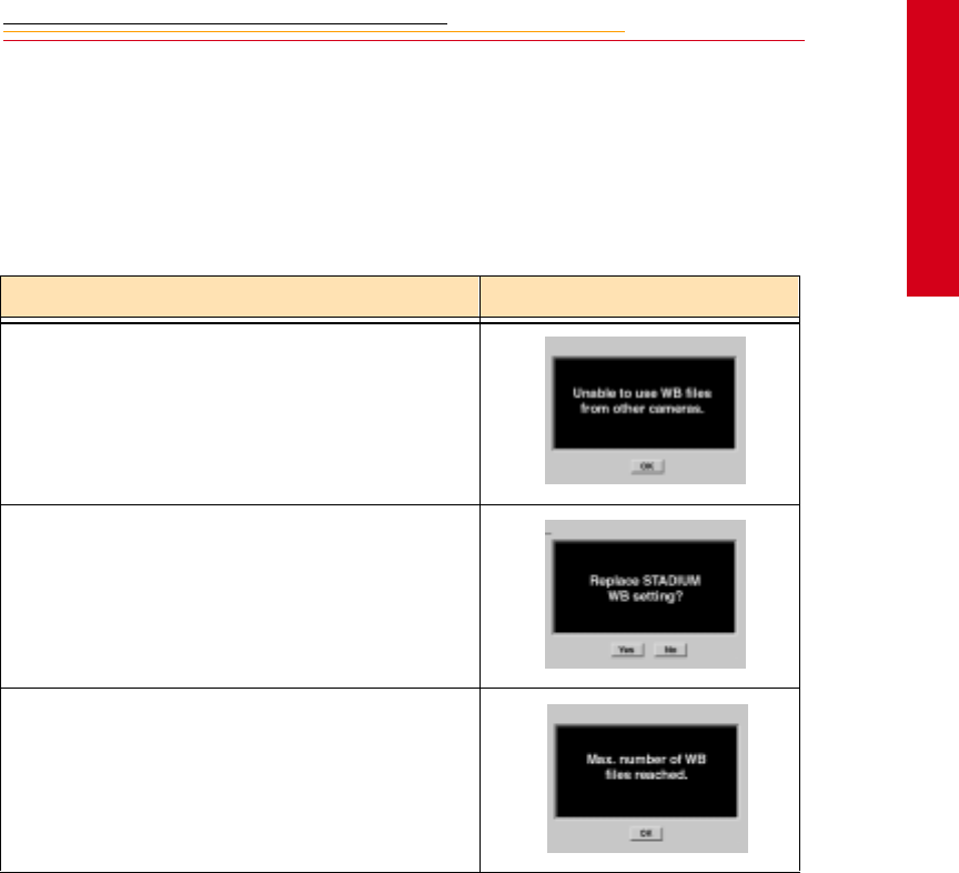
8-7
8
Exposure
Loading White Balance Settings
You can load White Balance settings from a PC Card into your camera. (The settings are
saved to the card using the DCS Host software.
There are a few rules to remember when you load White Balance settings. If you should
forget any of the rules, an appropriate error message appears, as shown in the table below.
Rule Error Message
You can only load settings into the camera that was
originally used to capture the images.
Each setting that you load must have a unique name.
Your camera holds up to ten Custom White Balance
settings.

8-8
1With the White Balance Setting
screen displayed (page 8-4),
choose Load from Card.
The Load White Balance Setting
screen appears with a list of the
White Balance settings on the
active PC Card. (If only one
card is in the camera, the card
choices do not appear.)
2Select the desired card. (You
may need to scroll up to the card
choices if there are numerous
White Balance settings.)
3Repeat step 2 to choose the
desired Custom White Balance
setting.
The setting is loaded from the
PC Card to your camera, and
appears in the list of settings.
☛When you load settings from a
PC Card, the last setting
loaded is the active White
Balance setting.

8-9
8
Exposure
Saving White Balance Settings using your Camera
You can save the current camera-generated White Balance settings, then apply the settings
to subsequently captured images.
Saving White Balance Settings using the Computer
You can also save White Balance settings to a PC Card using the DCS Acquire Module or
DCS TWAIN Data Source, then load the settings in your camera.
1Capture an image with a neutral area (such as a gray or white card) in the center.
2Using the DCS Acquire Module or DCS TWAIN Data Source, save the White Balance
setting to a PC Card. (Refer to the KODAK PROFESSIONAL DCS Host Software
User’s Manual.)
☛When you save a White Balance setting to a PC Card, a “.wb” extension is added to
the file name. For example, if you save the setting from a file named A0601385.TIF,
the setting will be named A0601385.wb on the PC Card.
3On your camera, select Custom White Balance (page 8-3).
4Load the White Balance setting from the PC Card to your camera (page 8-7).
5Select the desired Custom White Balance setting (page 8-6).
1Capture an image with a neutral
area (such as a gray or white
card) in the center.
2With the White Balance Setting
screen displayed (page 8-4),
choose Save (Image nnnn).
A confirmation screen appears.
3Select Yes to save the setting or
No to return to the White
Balance Settings menu without
saving.
If you save the setting, it appears
on the White Balance Settings
and the Delete White Balance
Settings screens.

8-10
Exposure Metering System
Your camera has three types of exposure metering systems:
✔3D Color Matrix Metering
✔Center-Weighted Metering (page 8-11)
✔Spot Metering (page 8-12)
3D Color Matrix Metering
With D-type AF Nikkor lenses (including AF-I or AF-S Nikkor), 3D Color Matrix
metering is automatically activated. 3D Color Matrix Metering uses various types of data:
scene brightness, scene contrast, focused subject’s distance (distance information) and
color distribution of the entire frame. Data on scene brightness, contrast and color
distribution is detected by the camera’s 1,005-pixel Matrix Sensor, while data on the
focused subject’s distance is detected and relayed by the D-type AF Nikkor lens.
Information on whether the main subject is centered is also detected. By analyzing this
data, your camera is able to provide correct exposure even in extremely complex lighting
situations.
☛The Matrix Metering system can only be used with lenses having a built-in CPU
(such as AF Nikkor and AI-P lenses.) Refer To Appendix C. If there is no lens
attached to your camera, 3-D Color Matrix Metering reverts to Center Weighted
metering.

8-11
8
Exposure
Center-Weighted Metering
With approximately 75% of the meter’s sensitivity concentrated on the 12 mm diameter
circle within the viewfinder and 25% outside this circle, the meter becomes useful in
situations where you want to base exposure on a specific area in the scene. To measure the
brightness of the picture’s off-center portion in auto exposure mode, use the camera’s
AE-L/AF-L button. Refer to “AE/AF Lock” on page 13-16.
You can change the diameter of the viewfinder circle using Custom
Setting #14. Refer to “Custom Settings” on page 13-32.
CUSTOM
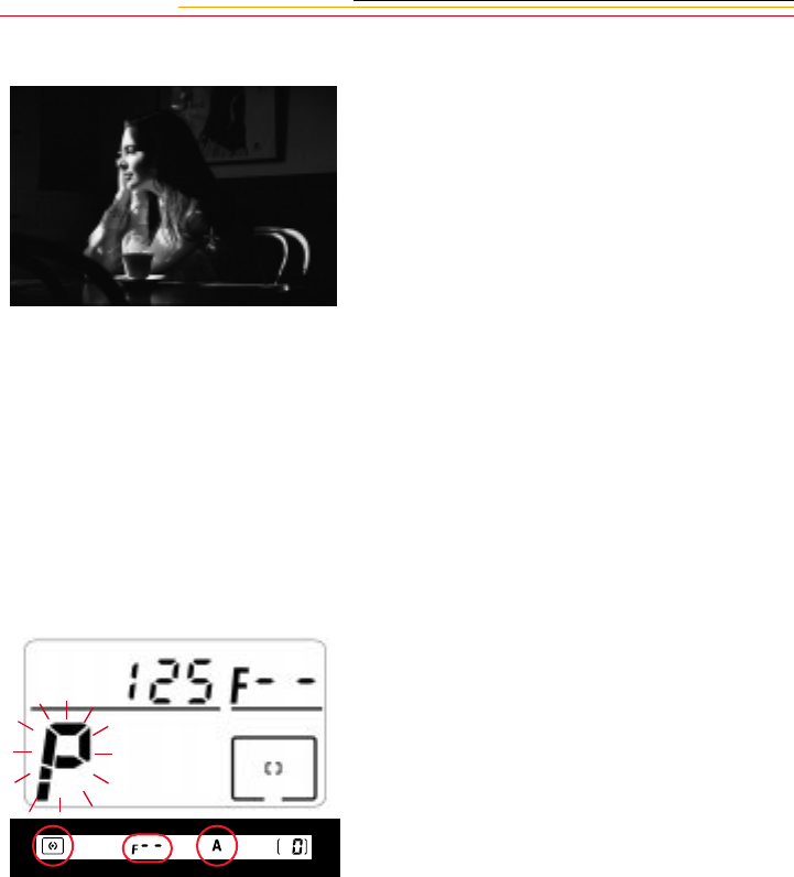
8-12
Spot Metering
Nearly 100% of the meter’s sensitivity is concentrated in a 4 mm diameter area
(approximately1.5% of the entire frame) within the selected focus area of the viewfinder.
(With focusing screens other than EC-B-type, the sensitivity is concentrated in a 6mm
diameter area or approximately 3.3% of entire frame.) Use this meter for highly selective
exposure control.
☛When Spot Metering is selected, shifting the focus area also shifts the Spot Metering
area to the corresponding position.
☛If you are using a lens without
a CPU, or accessories such as
bellows or extension rings, the
1,005-pixel 3D Color Matrix
Metering automatically
switches to Center-Weighted
Metering.
☛If Programmed Auto or
Shutter-Priority Auto is set,
the exposure mode switches
automatically to Aperture-
Priority Auto. The exposure
mode indicator blinks, F--
appears in the Top Status LCD
panel, and A appears in the
viewfinder. In this case, use
Center-Weighted Metering or
Spot Metering.
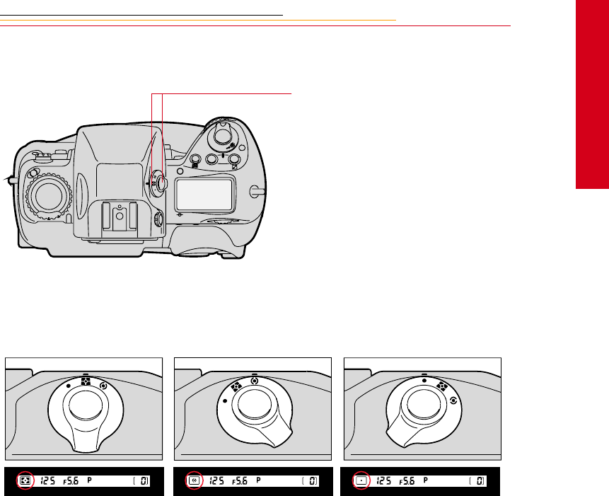
8-13
8
Exposure
Setting the Metering System
The appropriate symbol appears in the viewfinder.
Rotate the Metering System
Selector while pressing the
Metering System Selector Lock
Release to select the desired type of
exposure metering.
C
S
L
MODE
O
O
F
N
F
3D Color Matrix Metering Center-Weighted Metering Spot Metering

8-14
Exposure Mode
Light reaching the imager is controlled by the shutter speed and lens aperture. The proper
combination results in a correct exposure. Shutter speed and lens aperture settings are
based on the ISO speed and the operation of the camera’s exposure control system.
The relationship between aperture and shutter speed is described in the following
example:
A shutter speed of 1/500 second admits half the light of a shutter speed of 1/250
second and double the light of a shutter speed 1/1000 second.
An aperture of f/8 admits half the light of an aperture of f/5.6 and double the light of
an aperture of f/11.
If the correct exposure for a scene is 1/500 at f/8, you can also select 1/250 at f/11 or
1/1000 at f/5.6 and achieve the same exposure results.
In selecting the Exposure mode, you can choose whether you want to set the shutter speed
and/or lens aperture automatically or manually.
Your camera offers four types of exposure modes:
✔Programmed Auto (P)
✔Shutter-Priority Auto (S)
✔Aperture-Priority Auto (A)
✔Manual (M)
☛If there is no lens on your camera, or if you are using a non-CPU lens, Programmed
Auto or Shutter-Priority Auto modes do not work (even though a P or S appears in
the Top Status LCD panel). The camera will revert to Aperture-Priority Auto mode.
Programmed Auto Exposure Mode
With automatic selection of shutter speed and aperture, you can concentrate on image
composition without worrying about exposure. Programmed Auto Exposure mode is the
most commonly used Exposure mode.
☛Programmed Auto Exposure modes operate only with NIKON lenses that have a
built-in CPU (AF Nikkor and AI-P Nikkor lenses).
In Programmed Auto Exposure mode, you can use the Flexible Program function to
temporarily shift an automatically selected shutter speed/aperture combination and obtain
the desired shutter speed/aperture while retaining a consistent exposure. Refer to “Flexible
Program” on page 13-13.

8-15
8
Exposure
Shutter-Priority Auto Exposure Mode
This mode allows you to manually set your desired shutter speed. To freeze the action, use
a high shutter speed; to create motion effects, choose a slower shutter speed. Your camera
automatically selects the proper aperture to match the manually set shutter speed ensuring
a correct exposure. Refer to “Shutter-Priority Auto Exposure Mode” on page 13-1.
☛Note that Shutter-Priority Auto exposure mode operates only with NIKON lenses
having a built-in CPU (AF Nikkor and AI-P Nikkor lenses).
Aperture-Priority Auto Exposure Mode
By varying the aperture, you can control the depth of field. Smaller apertures make the
background and foreground sharper (recommended for landscapes) while larger apertures
tend to blur the background (recommended for portraits).
Your selected aperture determines the shutter speed that is automatically set by your
camera. When using smaller apertures with correspondingly slower shutter speeds,
remember that, generally, any speed below 1/(focal length in use) second, requires the use
of a tripod to prevent image blur due to camera shake. The higher the corresponding
shutter speed to the aperture you set, the easier it is to stop action. Adjust the selected
aperture if the speed is not appropriate for conditions or the specific effect you want. Refer
to “Aperture-Priority Auto Exposure Mode” on page 13-4.
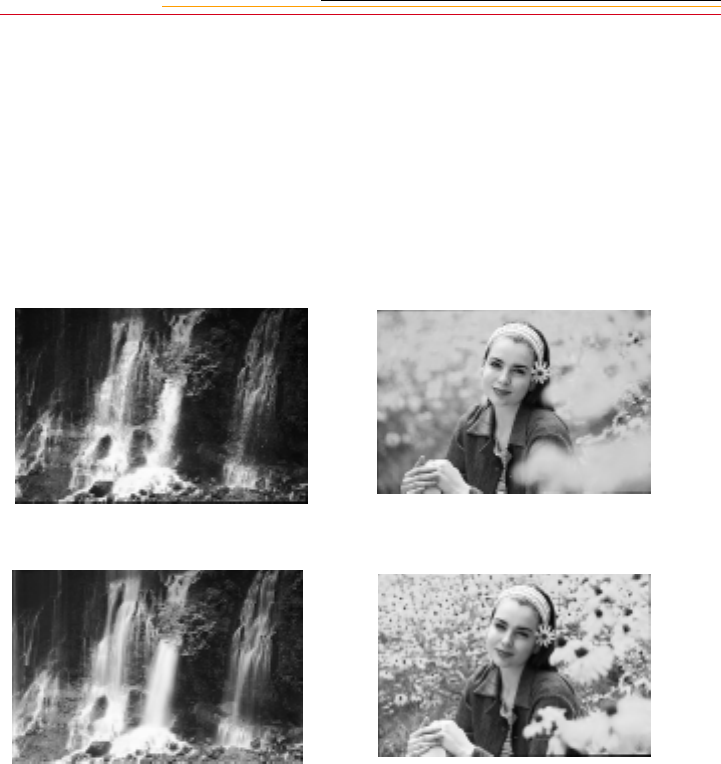
8-16
Manual Exposure Mode
The Manual exposure control allows you to change both aperture and shutter speed
settings. For a technically correct exposure, follow the recommendation of the camera’s
light meter, as indicated in the viewfinder. To achieve a specific creative effect (for
example, intentional blur, intentional under- or over-exposure), disregard the LCD and
modify the recommended exposure settings. Refer to “Manual Exposure Mode” on page
13-8.
Images captured at different shutter speeds Images captured at different apertures
High Shutter Speed Large aperture
Slow Shutter Speed Small aperture
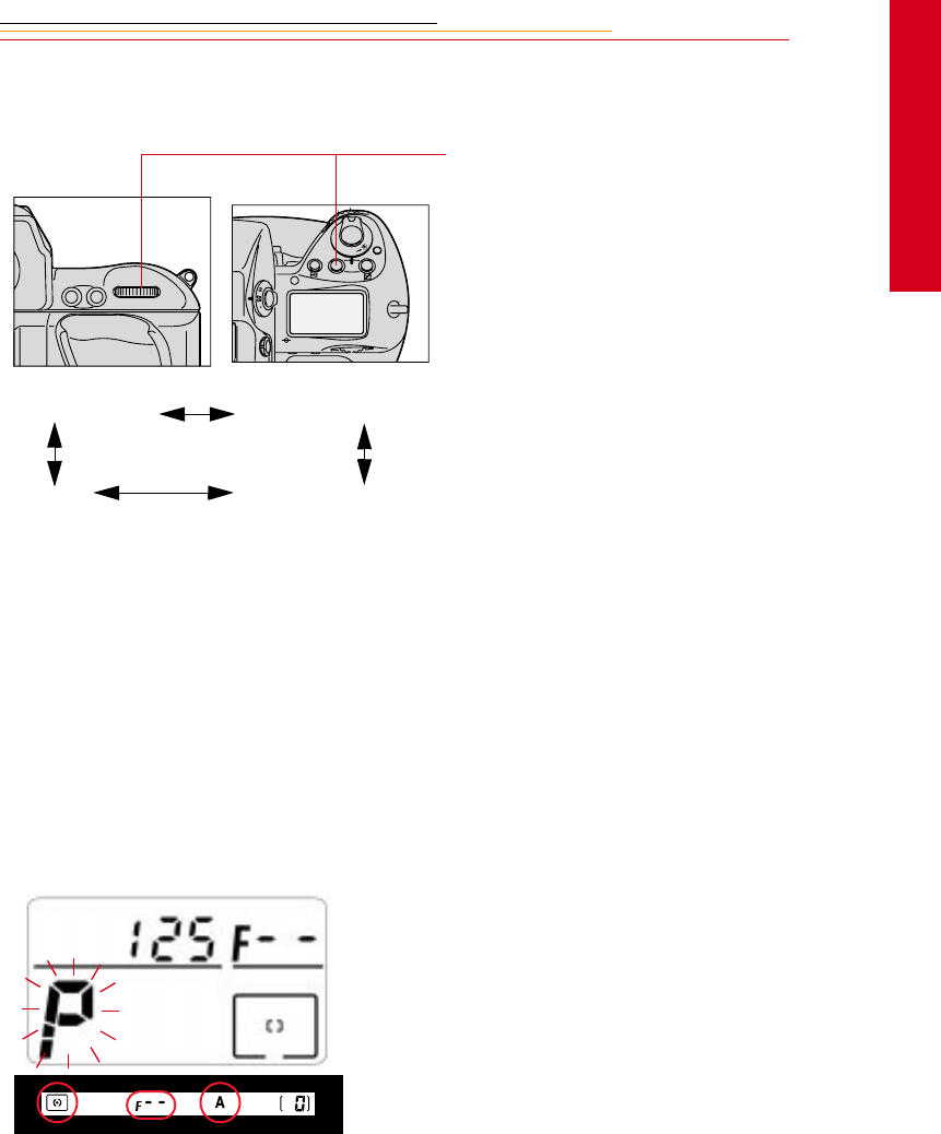
8-17
8
Exposure
Setting Exposure Mode
Rotate the Main-Command dial
while pressing the MODE button.
The exposure mode changes as in
the sequence shown at the left:
If you use lenses that don’t have a
CPU, or accessories such as a
bellows attachment or extension
rings:
✔Use Aperture-Priority Auto
or Manual exposure mode.
✔Programmed Auto or
Shutter-Priority Auto
exposure mode
automatically shift to
Aperture-Priority Auto
exposure mode.
✔F-- and the blinking
exposure mode indicator
appear in the Top Status
LCD panel, and A appears in
the viewfinder.
✔If 3D Color Matrix Metering
is set on the camera, the
metering system is also
automatically shifted to
Center-Weighted.
F
N
F
O
O
MODE
AF-ON
AF-L
AE-L
P Programmed Auto S Shutter-Priority Auto
M Manual A Aperture-Priority Auto
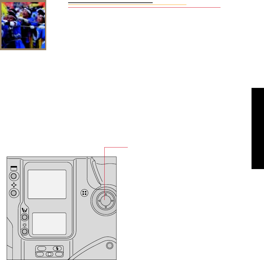
INSERT
PHOTO
HERE
9
Focusing
9-1
Focusing
9
This chapter discusses focus area, Focus mode, special focusing situations, and the effect
of the antialiasing filter on focus. It also discusses sharpening in the DCS 660 camera.
Focus Area
Five focus areas are available with your camera.
Selecting the Focus Area
To select the desired focus area,
press the top, bottom, left or right of
the Navigate switch.
ISO
BKT CSM
L
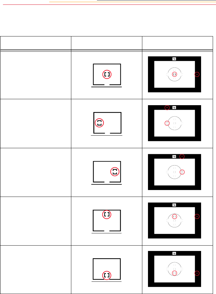
9-2
Corresponding focus areas appear in the Top Status LCD panel and the viewfinder.
Arrows on top and to the right of the viewfinder also indicate the selected focus area.
☛When Spot Metering is selected, shifting the focus area also shifts the Spot Metering
area accordingly.
Focus Area Top Status LCD panel Viewfinder
Center
Left
Right
Top
Bottom
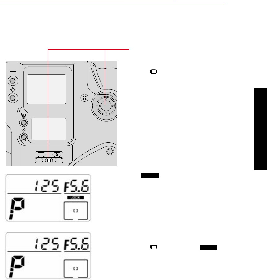
9-3
9
Focusing
Locking the Focus Area
You can lock the focus area using the lock function.
1Select the desired focus area,
then press the Navigate switch
to any position while pressing
the (Focus area lock) button.
appears above the focus
area icon in the Top Status LCD
panel
To release the lock, press the
Navigate switch while pressing
the button again so
disappears from the Top Status
LCD panel.
ISO
BKT CSM
L
L
LOCK
LLOCK
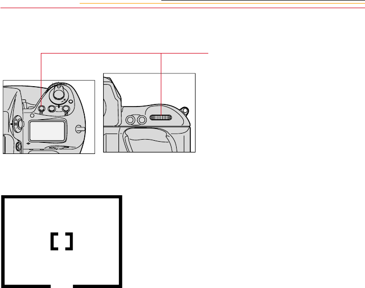
9-4
Selecting AF Area Mode
1Press and hold the AF area mode
button and rotate the Main-
Command dial to select Single
Area AF or Dynamic AF mode.
☛Single Area AF mode and
Dynamic AF mode are
described on the following
pages.
When Single Area AF mode is
selected, you may designate the
focus area, and that choice remains
unchanged regardless of subject
movement. A or appears in
the selected focus area of the Top
Status LCD panel.
The example at the left shows center
focus area selection
You may alternately choose any one
of the five available focus areas. In
Single Area AF mode, the sensor
calculates the focused distance by
using the selected focus area
exclusively.
F
N
F
O
O
MODE
AF-ON
AF-L
AE-L
[+]
Single Area AF
[ ]
[
]

9-5
9
Focusing
When Dynamic AF mode is
selected, a or appears in the
selected focus area, + appears in all
five focus areas of the Top Status
LCD panel, and all five AF sensors
are active.
The example at the left shows center
focus area selection.
In Dynamic AF mode, the selected
focus area designates the primary
sensor. This sensor is first to detect
a subject. If the subject moves, the
Dynamic AF operation
automatically shifts to the next
sensor that detects the subject,
progressively shifting among the
sensors. Dynamic AF is capable of
following and maintaining accurate
focus on moving subjects.
☛The viewfinder indication
does not change even though
the sensor is shifted.
[ ]
[
]
Dynamic AF

9-6
Focus Mode
Your camera has two focus modes: autofocus and manual.
Autofocus
There are two default Autofocus modes:
✔Single Servo AF with Focus-Priority
✔Continuous Servo AF with Release-Priority
In either of these modes—and in any Drive mode—focus tracking is automatically
activated when the subject starts moving. Exceptions to this are when you are using Single
Servo AF mode and the focus has already locked, or you are using Continuous Servo AF
mode and are pressing the AE-L/AF-L button. Refer to the “Single Servo AF with Focus-
Priority (Stationary Subject)” section on page 9-7 or the “Continuous Servo AF with
Release-Priority” section on page 9-9.
☛Do not attempt to turn the lens focusing ring or impede its rotation when the focus
mode selector is set to Single Servo AF (S) or Continuous Servo AF (C).
Custom Settings provide two Autofocus mode variations:
You can use Custom Setting #1 to assign Release-Priority to Single
Servo AF, and Custom Setting #2 to assign Focus-Priority to
Continuous Servo AF. Refer to “Custom Settings” on page 13-32.
CUSTOM
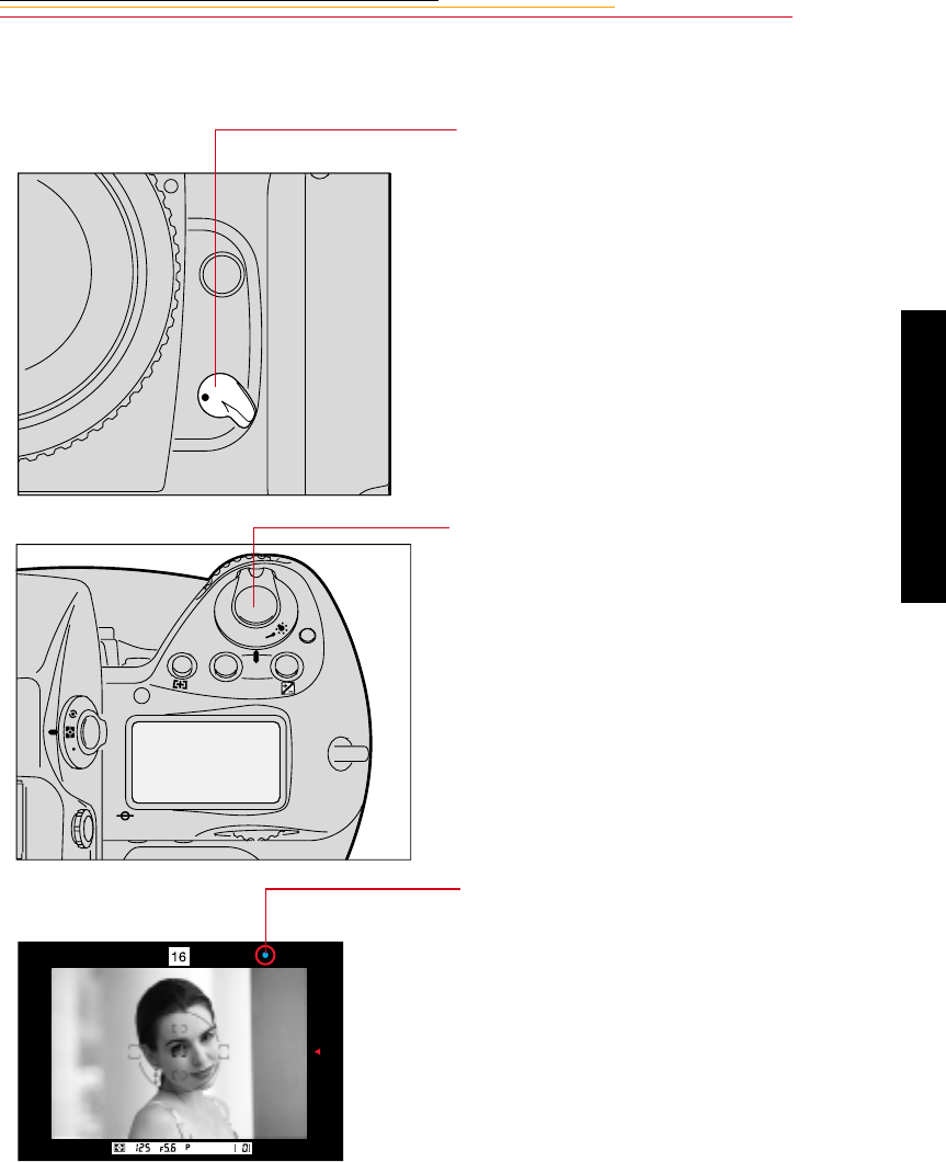
9-7
9
Focusing
Single Servo AF with Focus-Priority (Stationary Subject)
1Set the Drive Mode selector to S
(Single Servo AF).
2Lightly press the Shutter
Release button to activate
autofocus.
3Confirm that a green • appears in
the viewfinder, then fully
depress the Shutter Release
button.
☛If the subject moves before the
shutter releases, remove your
finger from the Shutter
Release button, then lightly
press it again to re-activate
autofocus.
C
S
M
F
N
F
O
O
MODE
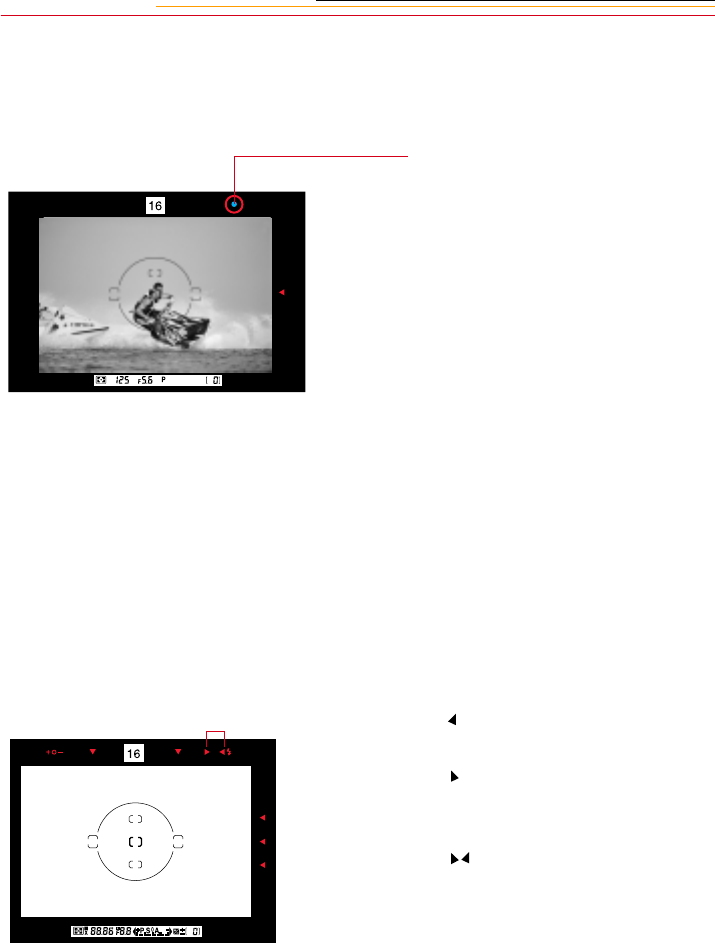
9-8
Single Servo AF with Focus-Priority (Moving Subject)
☛Single Servo AF is convenient for off-center subjects. Refer to “Focus Lock For Off-
center Subjects” on page 13-14.
1Perform steps 1 - 3 as for a
stationary subject (page 9-7).
2Confirm that a green • appears in
the viewfinder, then fully
depress the Shutter Release
button.
If you press the Shutter Release
button before the green • appears
in the viewfinder, the shutter is
released as soon as the subject
comes into focus.
Focus tracking remains
activated as long as you keep the
Shutter Release button lightly
pressed. If the subject stops
moving, and a green • appears,
focus is locked. If the subject
moves again, remove your
finger from the Shutter Release
button and lightly press it again
to start autofocus with focus
tracking.
If a appears in the viewfinder, the
lens is focused behind the subject.
If a appears in the viewfinder, the
lens is focused in front of the
subject.
If a blinks in the viewfinder,
autofocus is not possible. Refer to
“Special Focusing Situations in AF”
on page 9-13.
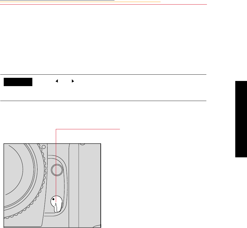
9-9
9
Focusing
☛After capturing images with the Drive mode set to S, you do not have to remove your
finger from the Shutter Release button to capture the next image. Slightly release
pressure on the button so it is only half-depressed, then fully depress it to release the
shutter again. The focus setting remains locked unless you remove pressure on the
button.
With the Drive mode set at CL, CH or CS, the camera refocuses every time the
shutter is released.
Continuous Servo AF with Release-Priority
The and which appear in the viewfinder display in Autofocus
mode can be canceled using Custom Setting #23. Refer to “Custom
Settings” on page 13-32.
1Set the Focus Mode selector to
C for Continuous Servo AF.
2Lightly press the Shutter
Release button.
Autofocus begins and the lens
continues to focus for as long as
you keep the Shutter Release
button lightly pressed. Because
the priority is on shutter release,
you can fully depress the Shutter
Release button regardless of
focus status. Whenever the
subject distance changes due to
recomposition or movement of
the subject, your camera
refocuses at the new distance.
CUSTOM
M
S
C
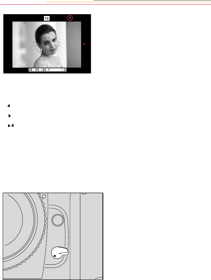
9-10
If a appears in the viewfinder, the lens is focused behind the subject.
If a appears in the viewfinder, the lens is focused in front of the subject.
If a blinks in the viewfinder, autofocus is not possible. Refer to “Special Focusing
Situations in AF” on page 9-13.
☛Focus is not locked in Continuous Servo AF. To capture an off-center subject, use the
AE-L/AF-L button and recompose the image. Refer to “AE/AF Lock” on page 13-
16.
Manual Focus
You can use the Electronic Rangefinder or the viewfinder’s clear matte field to ensure
precise manual focus.
Lightly press the Shutter Release
button to start autofocus. When the
subject is in focus, the camera’s
autofocus motor (or the motor of an
AF-I or AF-S Nikkor lens) stops
driving the autofocus lens and a •
appears in the viewfinder. Unless
you remove your finger from the
Shutter Release button, the motor
will start driving the lens again to
obtain an in-focus picture if the
focus distance changes.
To focus manually when using a
NIKON lens that does not have an
A/M switch, set the camera’s Focus
Mode selector to M.
When using a NIKON lens with an
A/M switch, set the lens’ switch to
M.
When using an AF-I or AF-S
Nikkor lens, set the switch on the
lens to M or M/A. (With these lens
types it is not necessary to change
the camera’s Focus Mode selector.)
S
M
C
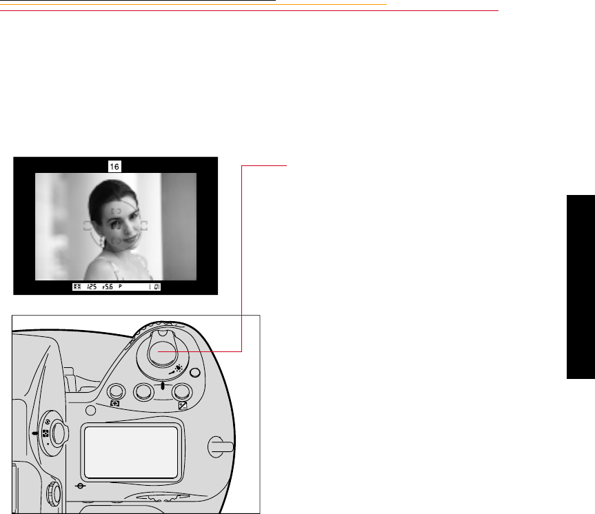
9-11
9
Focusing
Manual Focus with the Electronic Rangefinder
The Electronic Rangefinder provides you with viewfinder indications that show the focus
status while you are focusing. It works with most Nikon lenses (including AF Nikkor
when operated manually) having a maximum aperture of f/5.6 or faster. (For a complete
list of usable lenses, refer to the Lens Compatibility chart in Appendix C).
1Look through the viewfinder
and position the selected focus
bracket on the main subject,
then lightly press the Shutter
Release button.
You may select any focus
bracket.
F
N
F
O
O
MODE
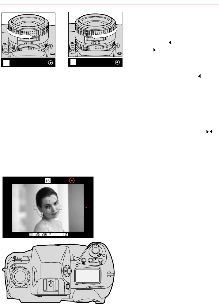
9-12
2While lightly pressing the
Shutter Release button, rotate
the lens focusing ring in the
direction indicated by the focus-
to-left arrow or focus-to-right
arrow , until the arrow
disappears and the in-focus
indicator • appears.
If the focus-to-left arrow does
not disappear when you turn the
focus ring counterclockwise to
its limit, the subject is too close
for the lens to focus. Move back
from the subject.
☛For special focusing situations
(described on page 9-13),
blinks to indicate that the
Electronic Rangefinder cannot
be used in this situation. Focus
with the clear matte field
(described on page 9-13).
3Confirm that the in-focus
indicator • appears, then fully
depress the Shutter Release
button to capture the image.
16 16
C
S
L
MODE
O
O
F
N
F
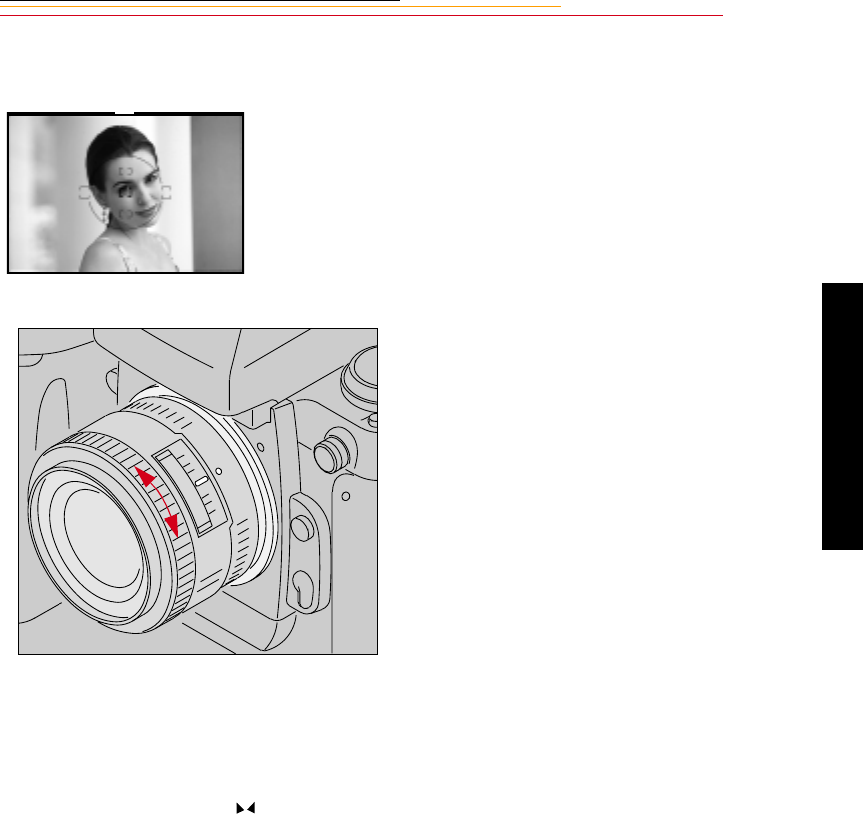
9-13
9
Focusing
Manual Focus Using a Clear Matte Field
Special Focusing Situations in AF
Autofocus operation depends on general lighting, subject contrast and detail, and other
technical factors. In rare situations where autofocus (and manual focus with the Electronic
Rangefinder) is not possible, blinks, telling you to focus manually with the clear matte
field (described on page 9-13) or perform autofocus on another subject located at the same
distance.
Look through the viewfinder and
rotate the lens focusing ring until
the image appears sharp.
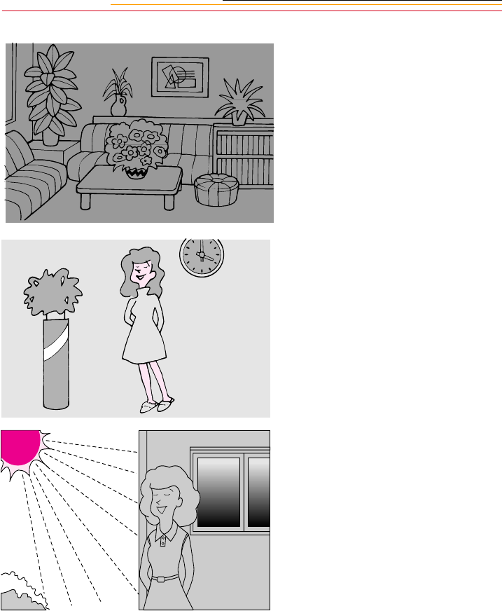
9-14
Very dark subject:
Focus manually with the clear
matte field, or for Single Servo
AF, focus on another brighter
subject located at the same
distance, then lock the focus
and recompose.
Refer to “Focus Lock For Off-
center Subjects” on page 13-
14.
Low-contrast subject
Focus manually with the clear
matte field, or for Single Servo
AF, focus on another subject at
the same distance but with
more contrast, then lock focus
and recompose. Refer to
“Focus Lock For Off-center
Subjects” on page 13-14.
Strong lighting
With a strongly backlit
subject, a bright or shiny
subject, or a scene in which
there is a pronounced
difference in brightness, use
Single Area AF mode and
select the subject’s focus area
(described on page 9-1) or
focus manually with the clear
matte field.

9-15
9
Focusing
In the following situations, ignore the in-focus indicator (•).
✔When the subject is obscured by an object such as a fence in the foreground, use
Single Area AF mode and select the subject’s focus area (described on page 9-1) or
focus manually with the clear matte field.
✔With an extremely bright object near your subject, use Single Area AF mode and
select the subject’s focus area, or focus manually with the clear matte field.
✔When using a linear polarizing filter or other special filter such as a soft-focus
filter, focus manually with the clear matte field.
☛A circular polarizing filter can be used in connection with autofocus operation.
Antialiasing Filter or IR Filter: Effect on Focus
The antialiasing or IR filters cause the distance indicator on your lens to show that an
object is closer than it actually is. This is particularly true when you use a wide angle lens.
The antialiasing filter also slightly increases the minimum distance at which you can
focus. It does not affect focusing, either manual or automatic.

9-16
Sharpening
Your DCS 620, 620x, or 660 camera is equipped with an antialiasing filter, an optical filter
that is mounted inside the camera in front of the electronic imager. This filter improves
overall image quality at the expense of a small loss of sharpness in the image. In general,
sharpen the image when the antialiasing filter is installed. There may be special situations
where you will not want to sharpen, or where you want to remove the antialiasing filter.
When you use the DCS Host software with your camera, you can specify whether you
want the image sharpened. To use the Sharpening feature, you may need to change settings
on both your camera and in the DCS Host software.
☛The Sharpening feature does not work with the 660M cameras.
The antialiasing filter uses optical design to reduce or eliminate the high-frequency image
patterning problems associated with single-shot digital capture and interpolation. The
optical effect causes a small change in how lenses perform compared to cameras without
the filter installed. The auto-focus capability adapts to the presence of the antialiasing
filter and will compensate for any variations under normal use.
If you choose Manual focus, be advised that zoom lenses experiences a shift in the focus
point as the focal length of the zoom is changed. If you zoom into your subject matter for
close focus, and then zoom out to compose your image, the focus point will change. This
is easily remedied by only focusing at the zoom setting that you will capture the image
with, or reverting to auto-focus and allowing the focusing computer to accommodate the
antialiasing filter’s optical effect.
Preparing for Sharpening in the DCS Host software
You can set a camera property that tells the DCS Host software whether sharpening should
be applied. Refer to “Enabling Sharpening” on page 4-4.
For information on the Sharpening function, refer to the KODAK PROFESSIONAL DCS
Host Software User’s Manual on the DCS Host Software CD included with your camera.

INSERT
PHOTO
HERE
Capturing
10
10-1
Capturing Images
10
This chapter provides an overview of the things you need to do to capture and manage
images. Much of the information is described in greater detail in other parts of the manual.
Preparing to Capture an Image
1Hold the camera properly.
2Stand with one foot forward a half step to balance your body.
3Grasp the camera hand grip with your right hand.
4Use your left hand to cradle the camera with your elbow propped against your body for
support, as you look through the viewfinder. Use your right index finger to press the
Shutter Release button.
5Check that nothing gets between your camera and the desired scene:
✔Do not block the lens with your hair or hand.
✔When capturing an image without looking through the viewfinder, make sure
nothing (such as your camera strap) is between your camera and the subject.
✔Do not block the flash during flash photography.
✔Do not block the White Balance sensor.
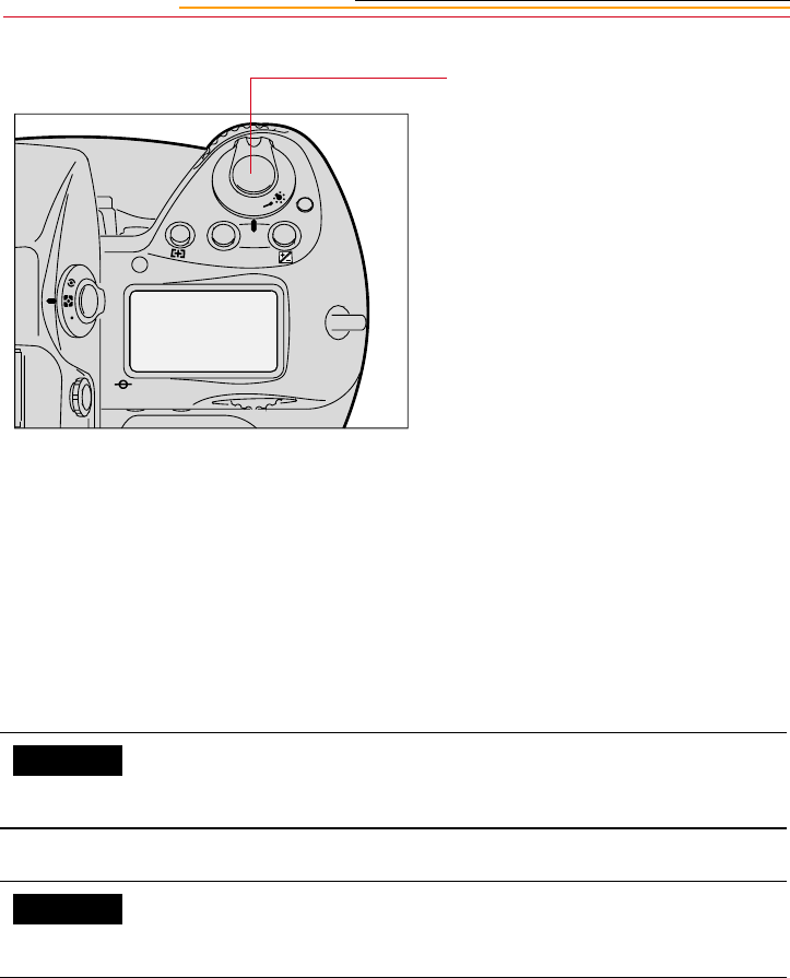
10-2
Lightly press the Shutter Release
button to start the autofocus
operation and switch the exposure
meter on.
Indicators inside the viewfinder and
Status LCD panels turn On. They
remain on for approximately 8
seconds after you take your finger
off the Shutter Release button, then
automatically turn Off.
Fully press the Shutter Release
button to release the shutter.
☛Press the Shutter Release
button slowly. Depressing the
Shutter Release button
abruptly may result in camera
shake.
To set the meter so the Status LCD panels turn Off after 4 seconds,
16 seconds, or 32 seconds, use Custom Setting #15. Refer to
“Custom Settings” on page 13-32.
To deactivate autofocus when the Shutter Release button is lightly
pressed, use Custom Setting #4. Refer to “Custom Settings” on page
13-32.
F
N
F
O
O
MODE
CUSTOM
CUSTOM
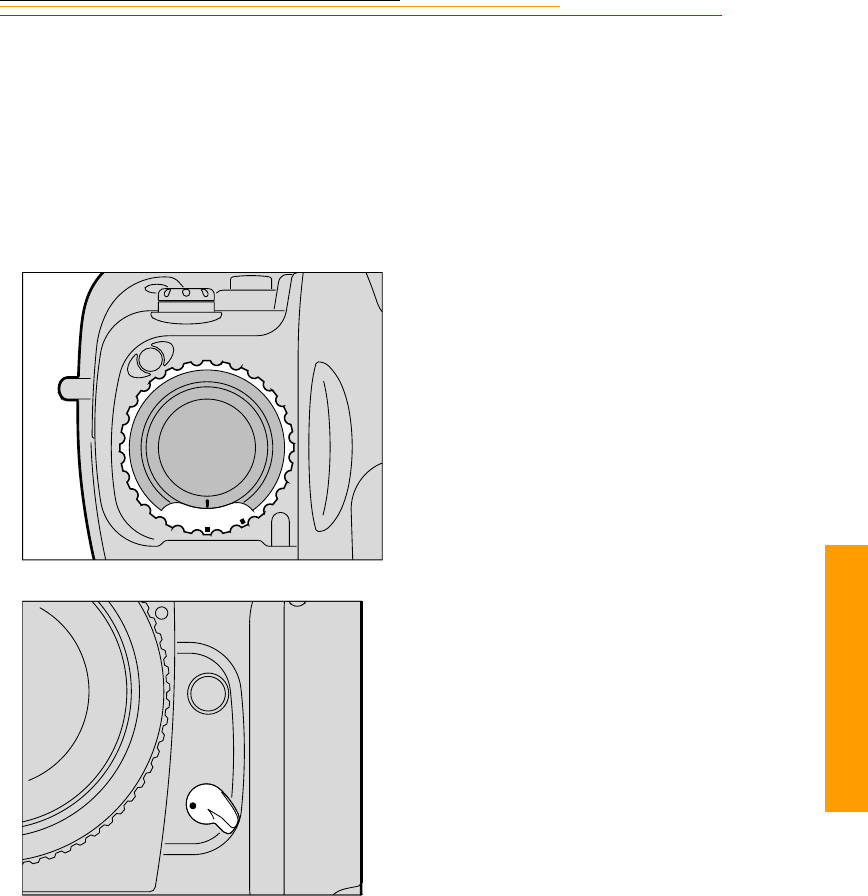
10-3
1
0
Capturing
Basic Shooting
1Set the lens aperture to its
minimum position. Refer to
“Setting the Lens to the
Minimum Aperture” on page 2-
22.
2Set the Drive Mode selector to S
for Single-frame shooting. Refer
to “Drive Mode” on page 10-10.
3Set the Focus mode selector to S
for Single Servo AF. Refer to
“Focus Mode” on page 9-6.
S
C
L
C
S
M
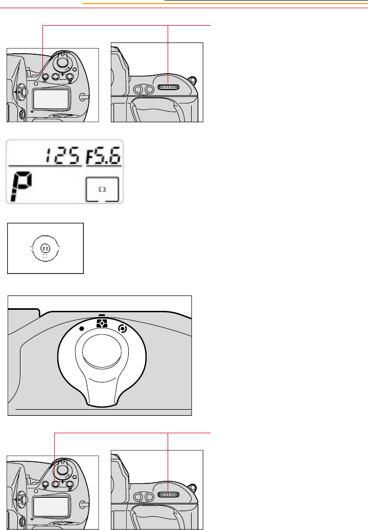
10-4
4Press and hold the AF area mode
button and rotate the Main-
Command dial to select Single
Area AF mode.
The selected focus area of the
Top Status LCD panel displays
only [ ].
The Focus bracket also appears
in the viewfinder.
5While pressing the lock release,
set the metering system selector
for 3D Color Matrix Metering.
Refer to “3D Color Matrix
Metering” on page 8-10.
6Press and hold the Exposure
Mode (MODE) button and
rotate the Main-Command dial
to select Programmed Auto
exposure mode.
AF-ON
AF-L
AE-L
F
N
F
O
O
MODE
AF-ON
AF-L
AE-L
F
N
F
O
O
MODE
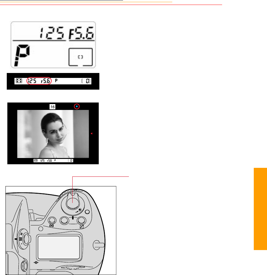
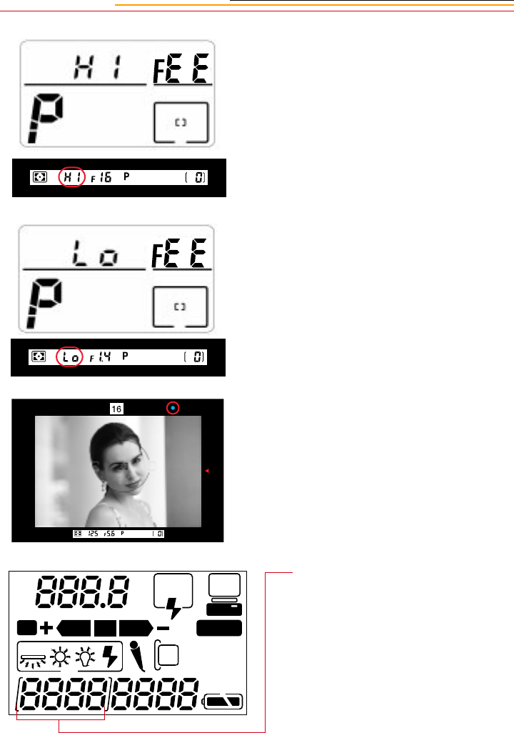
10-6
If HI appears in the shutter
speed position—Over-exposure
alert: Use a NIKON ND filter.
If Lo appears in the shutter
speed position—Under-
exposure alert: Use an accessory
NIKON Speedlight.
9Confirm that a • appears inside
the viewfinder (indicating
successful focusing), then fully
depress the Shutter Release
button to capture the image.
The frame number on the Back
Status LCD panel increases by
one.
REAR
SLOW
AUTO
ISO
BKT CUSTOM
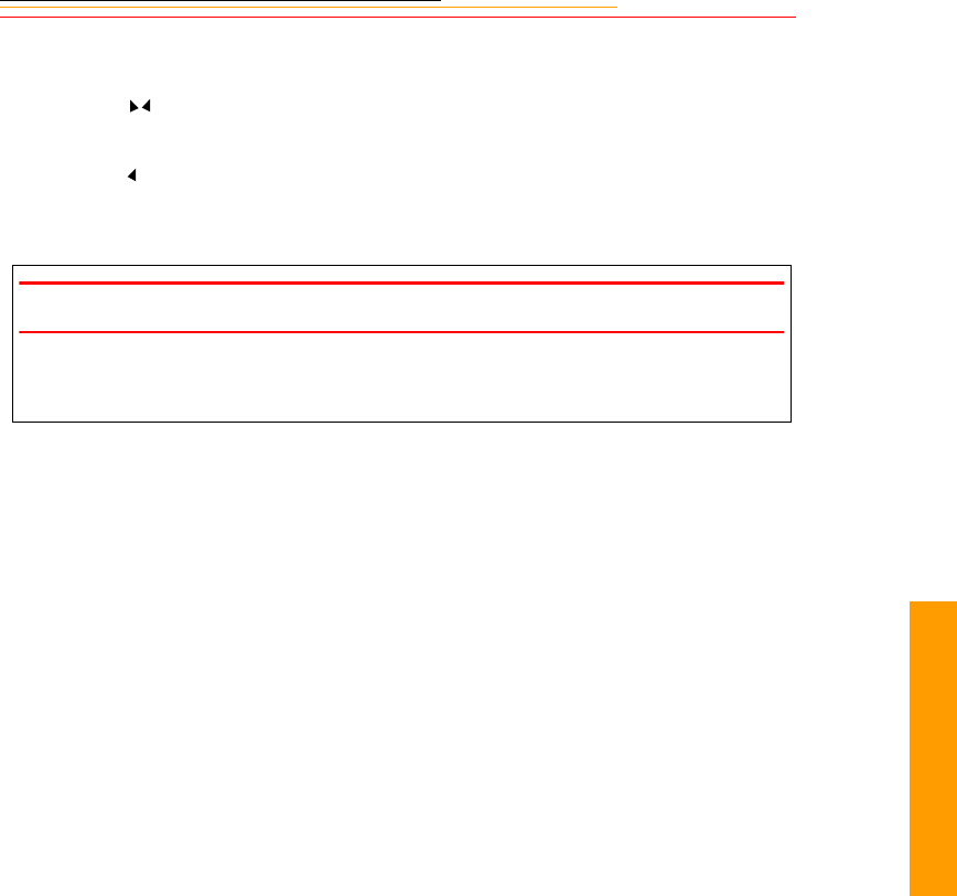
10-7
1
0
Capturing
The Shutter cannot be released in the following situations:
✔When blinks—Focus manually. Refer to “Special Focusing Situations in AF”
on page 9-13.
✔When appears—Subject is too close. Move away from your subject.
☛To conserve battery power, turn off the camera when you are not using it.
IMPORTANT:
Always remove batteries before storing your camera to prevent damage due to leaking
batteries.
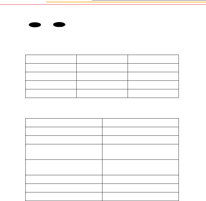
10-8
Two-Button Reset
Pressing the and buttons simultaneously for more than two seconds resets or
cancels various settings.
Two-Button Reset sets the following modes:
Two-Button Reset cancels the following modes:
Mode Set To Reference
Exposure mode Programmed Auto Page 8-14
AF Area mode Single Area AF Page 9-7
Focus Area Center Page 9-1
Flash Sync Front-Curtain Sync Page 11-13
Mode Effect
Flexible Program Cancelled
Exposure compensation 0.0
Auto Exposure/Flash Exposure
Bracketing Cancelled
Custom Setting Factory setting (except for
menu 0. See Page 13-32.
Shutter speed lock Cancelled
Aperture lock Cancelled
Focus area lock Cancelled
BKT CSM
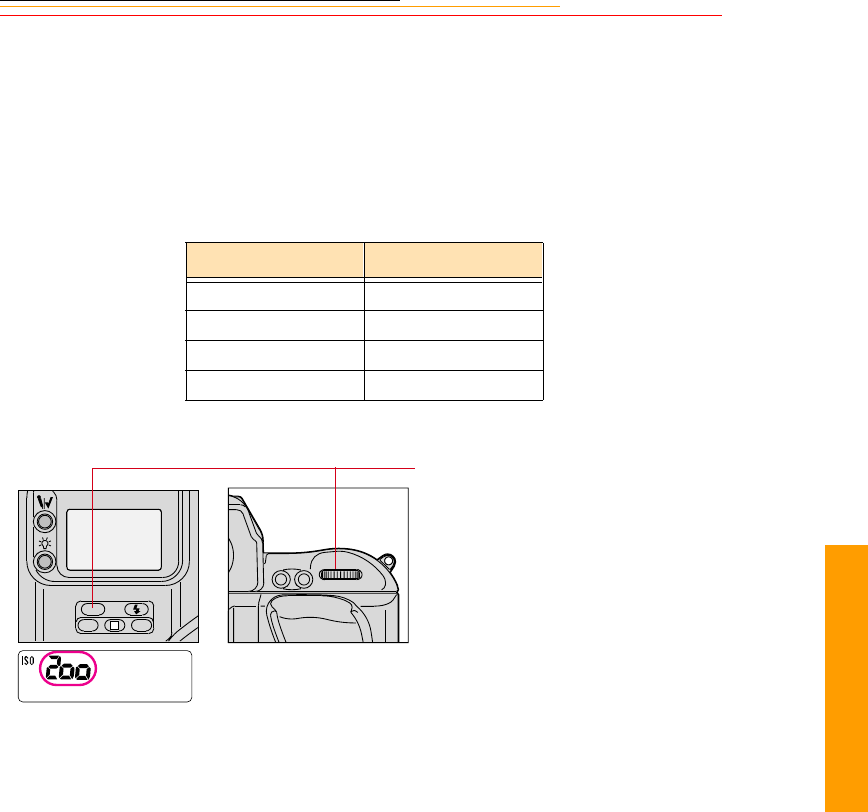
10-9
1
0
Capturing
ISO
The ISO setting controls imager sensitivity. The higher the number, the greater the
sensitivity, and vice versa. ISO 400 is twice as sensitive as ISO 200, and half as sensitive
as ISO 800.
The following table shows the ISO range for your camera:
Note on ISO (DCS 620x Only)
While the supported ISO range for the DCS-620x camera is 400 - 4000, the camera still
works at settings up to and including 6400. Settings above 4000 can degrade image
quality. In some instances you may want to use an ISO between 4000 and 6400. At these
times, it is suggested that you first capture some test images to determine results.
Camera ISO
DCS 620 200 - 1600
DCS 620x 400 - 4000
DCS 660 80 - 200
DCS 660M 320 - 800
Press and hold the ISO button and
rotate the Main-Command dial.
The setting appears in the Back
Status LCD panel.
AF-ON
AF-L
AE-L
L
CSMBKT
ISO
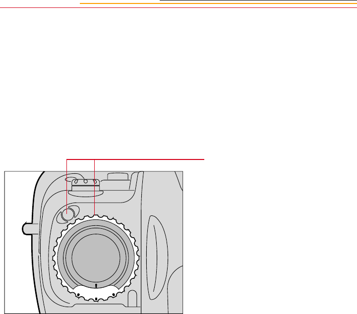
10-10
Drive Mode
Drive mode determines whether one or more images are captured when you are pressing
the Shutter Release button. There are four automatic Drive modes:
✔Single frame
✔Continuous low-speed shooting
✔Continuous high-speed shooting
✔Continuous silent-low-speed shooting
Choosing a Drive Mode
Rotate the Drive mode/Self-timer
selector while pressing the Drive
mode selector lock release. Set S for
Single-frame shooting, CL for
Continuous low-speed shooting, CH
for Continuous high-speed
shooting, or CS for Continuous
silent-low-speed shooting.
Defaults for these settings are:
DCS 620 and 620x: CL 2.0, CH
3.5, CS 1.0
DCS 660 and 660M: CL .15,
CH1.0, CS .15
You can change the settings for CH
and CL. Refer to “Custom Settings”
on page 13-32.
S
C
L
H
C

10-11
1
0
Capturing
Single-Frame Shooting
With the Drive mode at S, fully
pressing the Shutter Release button
captures one image. To capture the
next image, lift your finger from the
button, then fully press it again. Use
Single-frame shooting for stationary
subjects or subjects that do not
require several frames of rapid
firing.
S
C
L
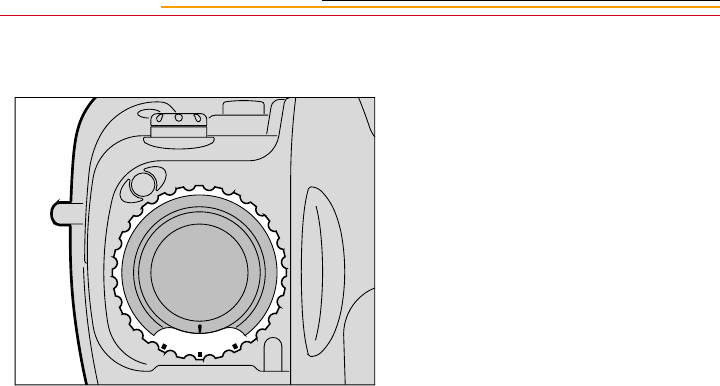
10-12
Continuous Shooting
Images are captured continuously as
long as you keep the Shutter
Release button fully pressed.
With the DCS 620 and 620x, you
can capture up to 3.5 fps in CH
mode, up to 2.0 fps in CL mode and
approximately 1.0 fps in CS mode.
With the DCS 660 and 660M, you
can capture up to 1.0 fps in CH
mode, and up to .15 fps in CL and
CS modes.
(These figures represent normal
temperature (20°C or 68°F) and a
shutter speed of 1/250 second or
higher in Manual exposure and
Continuous Servo AF modes. With
shutter speeds slower than 1/250
second, the framing rate becomes
progressively slower.
With the DCS 620 and 620x, the
buffer can fill when you capture
10 - 15 images in continuous
shooting mode. In this case, the
burst rate falls to 0.5 fps.
With the DCS 660 and 660M, the
buffer can fill when you capture up
to 3 images in continuous shooting
mode. In this case, the burst rate
falls to 0.15 fps.
☛You can change the setting for
shooting speed (DCS 620 and
620x only). Refer to “Custom
Settings” on page 13-32.
C
L
H
C
C
S
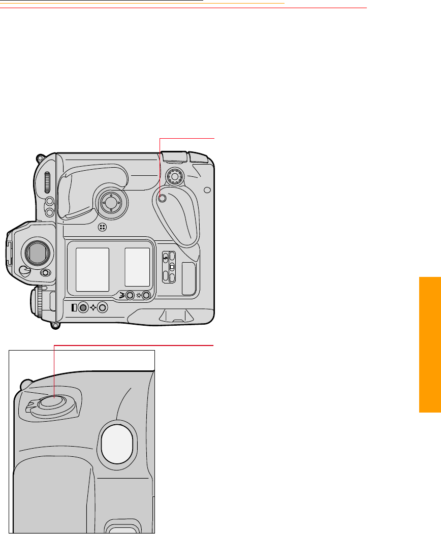
10-13
1
0
Capturing
Using the Vertical Controls
Your camera is designed to facilitate capturing images in a vertical orientation.
1Starting with the camera in the
normal position for capturing
images, turn it 90 degrees in a
counter clockwise direction.
2Press the Vertical AF Start
button if you plan to use
autofocus.
3Unlock the Vertical Shutter
release by turning the lock lever
and lining up the white dot with
the indentation on the camera.
4Press the Vertical Shutter
Release to capture an image.
5When you are finished, lock the
Vertical Shutter release by
turning the lock lever and lining
up the L with the indentation on
the camera.
☛This prevents you from
inadvertently bumping and
activating the Vertical Shutter
release.
L
CSMBKT
ISO

10-14
Intervalometer
Your camera has an Intervalometer which you can set so that a sequence of images are
captured automatically at specified intervals over a specified period of time. You might
use the Intervalometer to capture a flower bud opening or for unattended surveillance. You
can set the following:
✔Number of frames to be captured
✔Interval between exposures
✔Delay before the timer begins
✔Enable or disable the Intervalometer
The Intervalometer is disabled automatically after the specified time has elapsed, even if
the specified number of images have not been captured. For example, if you set the
Intervalometer for fifteen exposures at one second intervals, the camera would stop
capturing images after fifteen seconds, regardless of whether fifteen images had been
captured.
☛While the Intervalometer is enabled, the camera does not enter PowerSave mode.
1Select the Menu icon, then
choose Main Menu from the
dropdown menu. Refer to
“Navigation Techniques” on
page 2-14.
2Choose Intervalometer from the
Main menu.
The Intervalometer screen
appears.
3Select the desired setting.
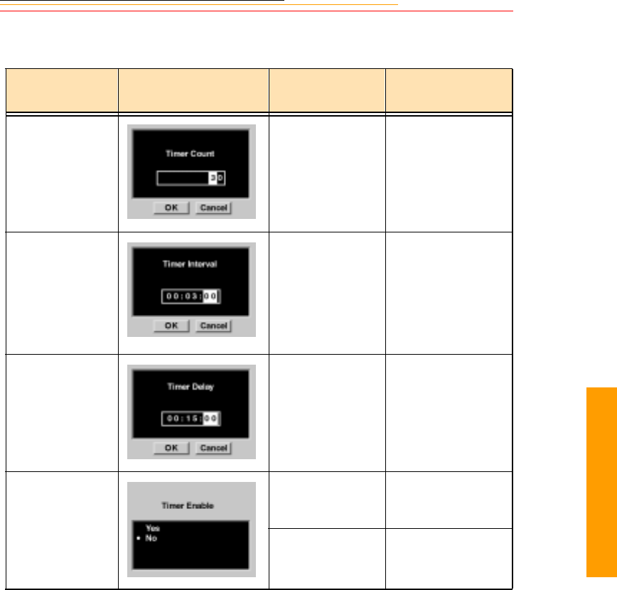
10-15
1
0
Capturing
Your choices on the Intervalometer screen cause the following screens to appear:
☛To change settings in these screens, use the same technique described for setting
Display Off Time. Refer to “Setting Display Off Time” on page 4-3.
Intervalometer
Settings Screen Your Action Result
Timer Count Set the timer
count—1-9999
frames
Default: 10 frames
Specifies the
number of frames to
be captured
Timer Interval Set the timer
interval—1 second
to 23:59:59
(HH:MM:SS)
Default: 10
seconds
Specifies the
interval between
image captures
Timer Delay Set the timer
delay—1 second
to 23:59:59
(HH:MM:SS)
Default: 1 second
Specifies the delay
before onset of the
Intervalometer
function
Timer Enable Select Yes Enables the
Intervalometer
function
Select No
Default: No
Disables the
Intervalometer
function
11-1
11
Flash
Flash Photography
11
The NIKON Autofocus SB-28D Speedlight has been specifically designed for DCS 600
Series cameras. This Speedlight retains all functionality of the NIKON SB-28 Speedlight
and adds functionality developed specifically for your camera.
Most of the SB-28D functionality is described in the SB-28 instruction manual (included
with your Speedlight) and you will need to refer to that manual. This chapter describes
only the functionality specific to your camera.
Recommendations for Flash Photography
The following settings are recommended when you use flash photography.
✔For better quality images with a greater choice of f-stops, the following ISO
settings are recommended:
DCS 620 and 620x: 200
DCS 660: 80
DCS 660M: 320
✔A (Aperture-Priority Auto) or P (Programmed Auto) exposure mode is
recommended as your camera will automatically choose the appropriate f-stop in
these modes.
✔You can also use S (Shutter-Priority Auto) or M (Manual) exposure mode, but be
careful that your camera does not go beyond the usable f-stops in dark lighting
conditions.
☛TTL flash is NOT recommended with your camera. Be aware that some flash units
default to TTL, and you will need to change the mode.
CAUTION:
Use only NIKON Speedlights. Other units may damage your camera’s electrical
circuits due to incompatible voltage requirements, electrical contact alignment, or
switch phase. Your camera is not compatible with voltages of 250V or higher.

11-2
Auto Aperture Mode
While a variety of flash modes are available with the SB-28D Speedlight, only Auto
Aperture mode is discussed in this Chapter. (Others are discussed in the SB-28 instruction
manual.)
Auto Aperture mode has been developed specifically for your camera. Auto Aperture
mode automatically controls flash output to achieve correct exposure for both the subject
and background. When you use Auto or Manual Exposure modes, your camera
automatically adjusts shutter speed and aperture size according to scene brightness in
ambient light. The SB-28D Speedlight adjusts the flash output based on the f-stop in use,
thus ensuring proper exposure.
You should use Auto Aperture mode for flash photography with your camera. TTL auto
flash is NOT recommended.
Auto Aperture mode works only when you use D-type AF Nikkor lenses, AF Nikkor
lenses (except for AF Nikkor for F3AF) or AI-P Nikkor lenses. Refer to Appendix C for
more information.
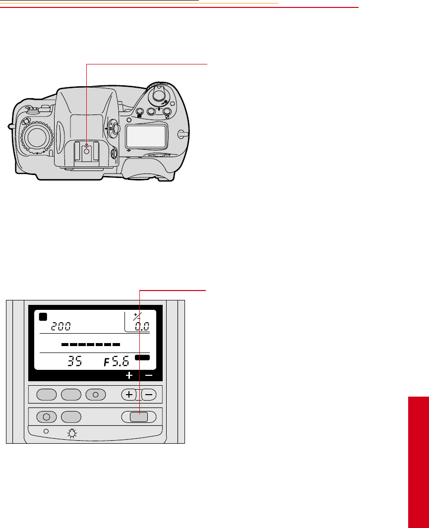
11-3
11
Flash
Attaching the SB-28D or SB-28DX
Turning on the SB-28D or SB-28DX
1Mount the SB-28D onto your
camera’s accessory shoe.
The red flash symbol appears in
the viewfinder when a flash is
installed.
2Attach one of the following
lenses:
✔D-type AF Nikkor lens
✔AF Nikkor lens (except for
AF Nikkor for F3AF)
✔AI-P Nikkor lens
1Turn on the camera.
2Turn on the Speedlight by
pressing its ON/OFF button for
approximately 0.5 seconds.
C
S
L
MODE
O
O
F
N
F
SELMODEZOOM
ISO
ZOOM
mm
m
181396431.510.6 0.8 2
FLASH
ON / OFF
A
STBY
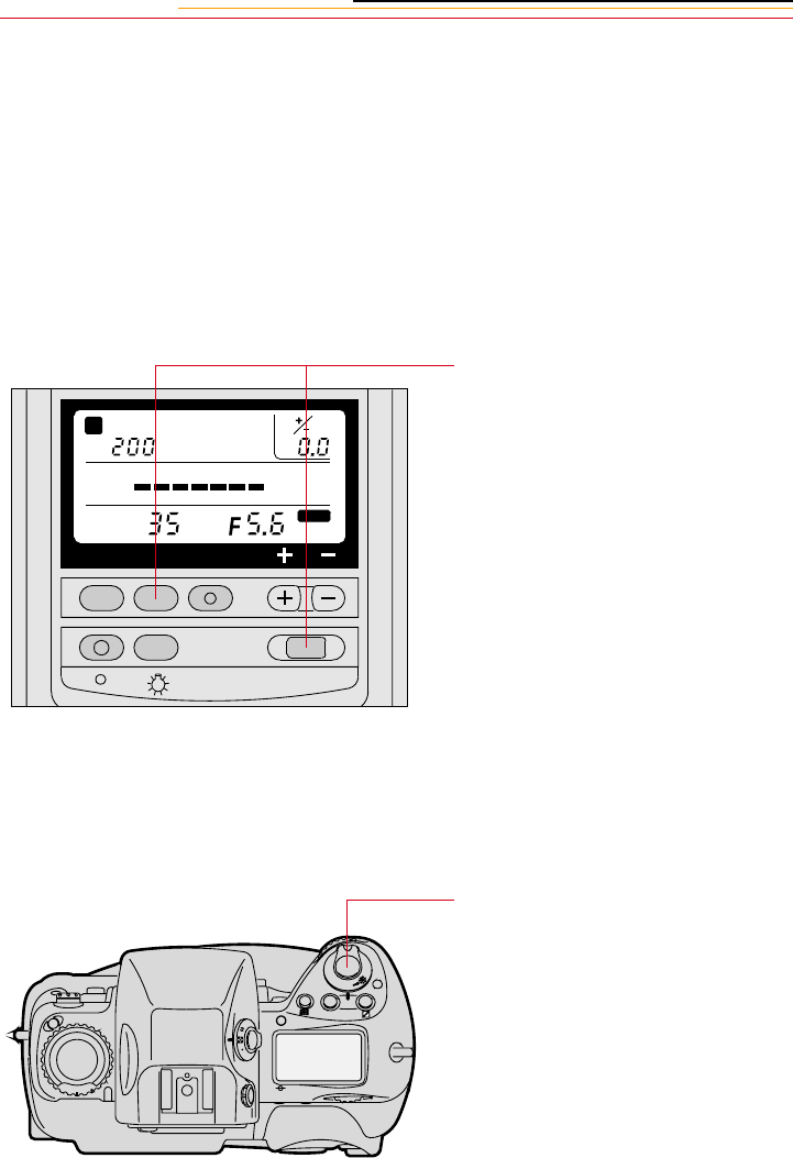
11-4
Standby Mode
The SB-28D features a Standby mode that helps conserve the battery in your Speedlight.
When the Speedlight is in this mode, it will go to sleep if you don’t touch any camera or
Speedlight controls for 80 seconds. STBY appears in the Speedlight’s LCD panel when
the flash is in Standby mode.
Enabling/Disabling Standby Mode
You can enable or disable Standby mode according to your personal preference.
Waking the SB-28D or SB-28DX from Standby mode.
If your Speedlight goes to sleep while in Standby mode, you can “wake” it by doing the
following:
Hold the Speedlight’s MODE
button and press its ON/OFF button.
If the Speedlight was in Standby
mode, Standby mode will be
disabled. If not, Standby mode will
be enabled.
STBY appears in the Speedlight’s
LCD panel when the Speedlight is in
Standby mode.
Lightly press the camera’s Shutter
Release button.
The Speedlight wakes up
automatically
SELMODEZOOM
ISO
ZOOM
mm
m
181396431.510.6 0.8 2
FLASH
ON / OFF
A
STBY
C
S
L
MODE
O
O
F
N
F
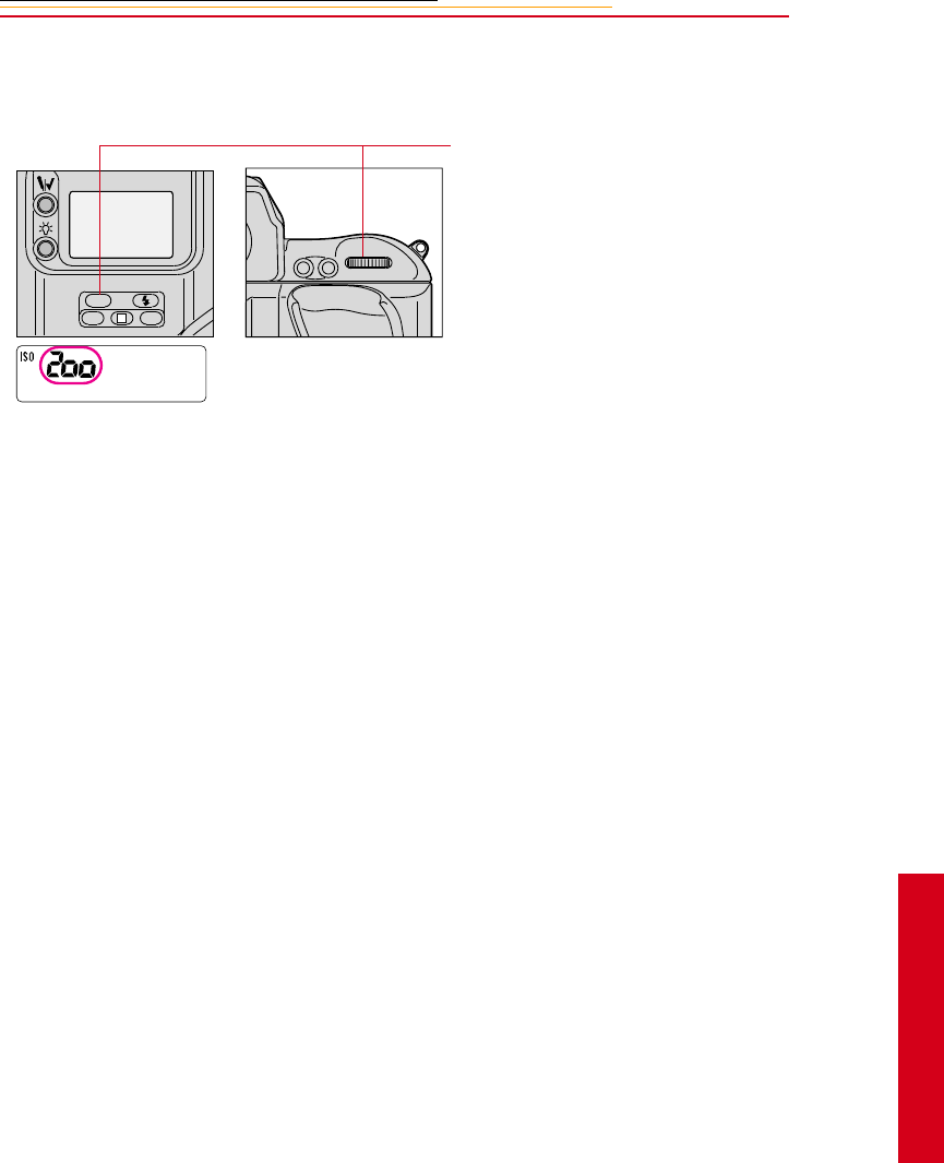
11-5
11
Flash
Setting Up Your Camera for Flash Photography
1Press and hold the ISO button
and rotate the Main-Command
dial to set the desired ISO.
Refer to “ISO” on page 10-9.
The setting appears in the Back
Status LCD panel.
2Confirm that you are using a
D-type AF Nikkor lens, AF
Nikkor lens (except for AF
Nikkor for F3AF) or AI-P
Nikkor lens.
If you use a different type of
lens, Auto Aperture mode will
not be possible. (In this case,
Non-TTL Auto Flash mode is
r e c o m m e n d e d . ) R ef e r t o t h e
“Non-TTL Auto Flash Mode”
section of the SB-28 instruction
manual.
3Set the lens to the minimum
aperture.
AF-ON
AF-L
AE-L
L
CSMBKT
ISO

11-6
4Set Exposure mode. Refer to
“Capturing Images in Each
Exposure Mode” on page 13-1.
While you can use any exposure
mode, Aperture Priority (A) or
Program (P) are recommended.
Manual (M) or Shutter Priority
(S) modes are not recommended
as they allow you to set an f-stop
which is out of range for Auto
Aperture mode.
If you set Manual or Shutter
Priority mode, the f-stop
indicator on the flash LCD panel
flickers and the indicator bars
disappear.
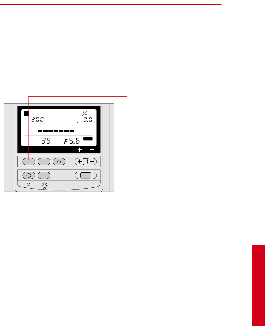
11-7
11
Flash
Setting Up the SB-28D or SB-28DX
Whenever you mount the SB-28D on your camera, the Flash mode is automatically set to
Auto Aperture mode.
The Mode indicator on the Speedlight’s LCD panel shows A.
If the f-stop indicator on the Speedlight’s LCD panel flickers and the indicator bars
disappear, the f-stop is out of usable range. Choose a different aperture.
1Press the ZOOM button to set
the Zoom setting at the same (or
wider) f-mm as that of the lens
in use.
In the automatic Zoom setting,
the flash beam coverage always
follows the picture field angle of
the lens in use. The ZOOM
button allows you to change the
flash beam coverage. Refer to
the SB-28 instruction manual.
2Set the Exposure compensation
level to zero EV or to the desired
level. Refer to the SB-28D
instruction manual.
The compensation level is shown
at the upper right of the
Speedlight’s LCD panel.
SELMODEZOOM
ISO
ZOOM
mm
m
181396431.510.6 0.8 2
FLASH
ON / OFF
A
STBY
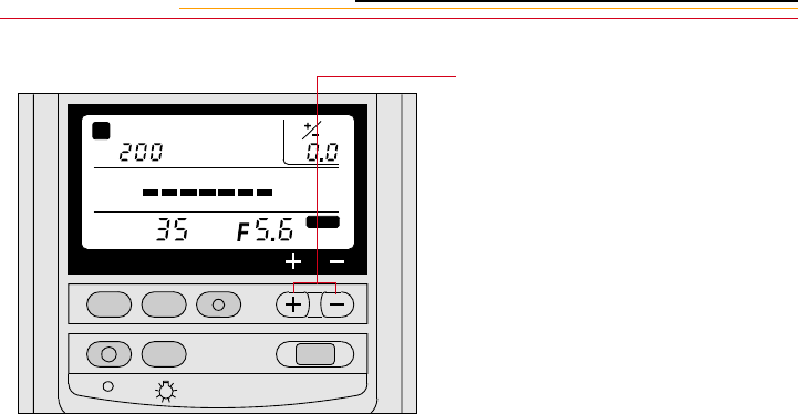
11-8
The Plus (+) and minus (-)
buttons allow you to set the
appropriate compensation level
in 1/3EV increments from - 3EV
to + 1EV in Auto Aperture
mode.
The following list provides
information specific to the
different zones. Refer to “Auto
Flash Distance Range” on page
11-11.
✔Negative exposure
compensation is not possible
in Zone A.
✔Exposure compensation
exceeding -1EV is not
possible in Zone B.
✔Exposure compensation
exceeding -2EV is not
possible in Zone C.
✔Exposure compensation
exceeding +1EV is not
possible in Zone D.
✔Exposure compensation
from - 3EV to +1EV is
possible in other zones.
SELMODEZOOM
ISO
ZOOM
mm
m
181396431.510.6 0.8 2
FLASH
ON / OFF
A
STBY
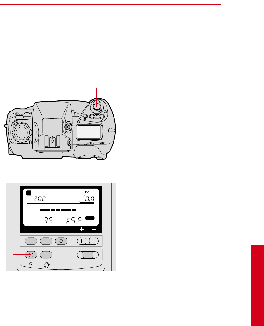
11-9
11
Flash
Test Firing
You can test to determine if a subject is within the appropriate distance range for the
current aperture.
1Turn on the camera.
2Turn on the Speedlight.
3Lightly press the Shutter
Release button, then release.
4Aim the Speedlight at the
subject and press its FLASH
button
5Confirm that the Ready light is
On.
If the Ready lights on the
Speedlight and inside the
camera viewfinder blink for
approximately 3 seconds after
the firing, the light may have
been insufficient for correct
exposure. If this occurs, use a
wider aperture or move closer to
the subject before capturing
images. Refer to the SB-28
instruction manual.
In Auto Aperture mode, the
camera determines the aperture
and the flash conducts auto flash
with that f-stop.
C
S
L
MODE
O
O
F
N
F
SELMODEZOOM
ISO
ZOOM
mm
m
181396431.510.6 0.8 2
FLASH
ON / OFF
A
STBY
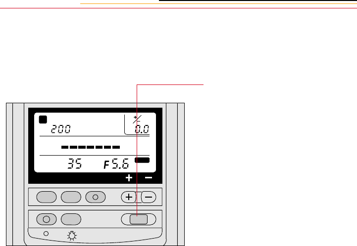
11-10
Using the SB-28D
.
1Turn on the camera.
2Turn the Speedlight On by
pressing its ON/OFF button for
approximately 0.5 seconds.
The Speedlight’s Ready light
comes on as soon as the flash is
recycled and ready to fire.
☛If your subject is relatively far
off, wait several seconds after
the Ready light turns on before
capturing the image.
3Aim the camera at the subject.
4Press the Shutter Release button
to capture the image.
☛If the Ready lights on the
Speedlight and inside the
camera viewfinder blink for
approximately 3 seconds after
you capture the image, the
light may be insufficient for
correct exposure. If this
occurs, use a wider aperture or
move closer to the subject
before capturing any more
images.
5Wait for a few seconds until the
Ready light comes on again
indicating that the flash is ready.
Capture a few more images,
changing exposure
compensation on the flash or on
the camera, as needed.
SELMODEZOOM
ISO
ZOOM
mm
m
181396431.510.6 0.8 2
FLASH
ON / OFF
A
STBY

11-11
11
Flash
Auto Flash Distance Range
The LCD panel will not show the f-stop nor indicator bars when the f-stop is out of range.
Your camera works within the following ISO range:
DCS 620: 200 - 1600
DCS 620x: 400 - 4000
DCS 660: 80 - 200
DCS 660M: 320 - 800
F
ISO Number
(f/number)
Distance Range According to Zoom Settings
(Upper figures are in feet, lower figures are in meters)
80 200 400 800 1600 18mm 20mm 24mm 28mm 35mm 50mm 70mm 85mm
Zone
A
2 2.8 4 5.6 8 2.6~29
0.8~9
2.9~32
0.9~10
4.4~49
1.4~15
4.7~52
1.5~16
5.2~59
1.6~18
6.1~66
1.9~20
7.0~66
2.2~20
7.2~66
2.2~20
Zone
B
2.8 4 5.6 8 11 2.0~20
0.6~6.
3
2.1~23
0.7~7.
0
3.1~34
1.0~10
3.3~37
1.0~11
3.7~41
1.2~12
4.3~48
1.4~14
4.9~55
1.5~16
5.1~57
1.6~17
Zone
C
4 5.6 8 11 16 2.0~14
0.6~4.
5
2.0~16
0.6~5.
0
2.2~24
0.7~7.
5
2.4~26
0.7~8.
0
2.6~29
0.8~9.
0
3.0~34
1.0~10
3.5~39
1.1~12
3.6~41
1.1~12
O
t
h
e
r
Z
o
n
e
s
5.8 8 11 16 22 2.0~10
0.6~3.
1
2.0~11
0.6~3.
5
2.0~17
0.6~5.
3
2.0~18
0.6~5.
6
2.0~20
0.7~6.
3
2.2~24
0.7~7.
4
2.5~27
0.8~8.
4
2.6~28
0.8~8.
8
8 11162232 2.0~7.
3
0.6~2.
2
2.0~8.
2
0.6~2.
5
2.0~12
0.6~3.
7
2.0~13
0.6~4.
0
2.0~14
0.6~4.
5
2.0~17
0.6~5.
2
2.0~19
0.6~6.
0
2.0~20
0.6~6.
2
11 16 22 32 45 2.0~5.
20.6~1
.5
2.0~5.
7
0.6~1.
7
2.0~8.
6
0.6~2.
6
2.0~9.
2
0.6~2.
8
2.0~10
0.6~3.
1
2.0~12
0.6~3.
7
2.0~13
0.6~4.
2
2.0~14
0.6~4.
4
18 22 32 45 64 2.0~3.
6
0.6~1.
1
2.0~4.
1
0.6~1.
2
2.0~6.
1
0.6~1.
8
2.0~6.
5
0.6~2.
0
2.0~7.
3
0.6~2.
2
2.0~8.
6
0.6~2.
6
2.0~9.
8
0.6~3.
0
2.0~10
0.6~3.
1
22 32 45 64 - 2.0~2.
6
0.6~0.
7
2.0~2.
8
0.6~0.
8
2.0~4.
3
0.6~1.
3
2.0~4.
6
0.6~1.
4
2.0~5.
2
0.6~1.
5
2.0~6.
0
0.6~1.
8
2.0~6.
9
0.6~2.
1
2.0~7.
2
0.6~2.
2
Zone
D
32 45 64 - - - 2.0
0.6
2.0~3.
0
0.6~0.
9
2.0~3.
2
0.6~1.
0
2.0~3.
6
0.6~1.
1
2.0~4.
3
0.6~1.
3
2.0~4.
9
0.6~1.
5
2.0~5.
1
0.6~1.
5

11-12
The range of f-stops for your camera in Auto Aperture mode is:
ISO 80: F/2 to F/32
ISO 200: F/2.8 to F/45
ISO 400: F/4 to F/64
ISO 800: F/5.6 to F/64
ISO 1600: F/8 to F/64
Minus exposure compensation is not possible in Zone A. Exposure compensation
exceeding -1EV is not possible in Zone B. Exposure compensation exceeding -2EV is not
possible in Zone C. Plus Exposure compensation is not possible in Zone D. Exposure
compensation from - 3EV to +1EV is possible in other Zones.
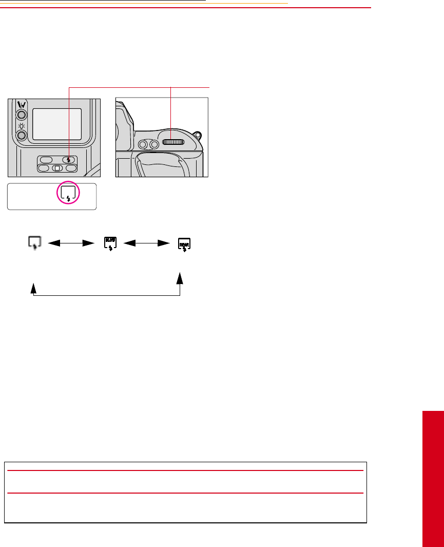
11-13
11
Flash
Flash Sync Mode
Flash Sync mode lets you modify how and when the flash fires during exposure.
Slow Sync
Making a Dark Background More Visible
Without Slow Sync, the automatically controlled shutter speed is controlled between
1/250 second and 1/60 second. When flash pictures are taken with this rather narrow
shutter speed range in dim light, the subject appears bright and well exposed, but the
background may appear very dark, almost black. Setting Slow Sync extends the automatic
controlled shutter speed range down to 30 seconds, enabling background details to stand
out.
Press and hold the Flash Sync Mode
button and rotate the Main-
Command Dial to select the desired
flash sync mode.
☛If you are using a non-NIKON
flash unit and select Normal
Sync mode, the icon
disappears from the Back
Status LCD panel after you
release the Flash Sync Mode
button.
The flash sync mode changes as in
the sequence shown at the left.
IMPORTANT:
To avoid image blur, attach the camera to a tripod.
AF-ON
AF-L
AE-L
L
CSMBKT
ISO
Front-Curtain Sync Slow Sync Rear-Curtain Sync
(Normal Sync)
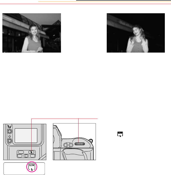
11-14
1Set the Exposure mode to P for
Programmed Auto or A for
Aperture-Priority Auto. Refer to
“Setting Exposure Mode” on
page 8-17.
2Press and hold the camera’s
Flash Sync Mode button and
rotate the Main-Command dial
until appears in the Back
Status LCD panel.
Slow Sync Normal Sync
AF-ON
AF-L
AE-L
L
CSMBKT
ISO
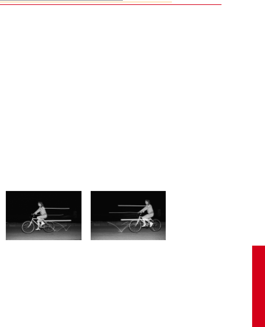
11-15
11
Flash
Rear Curtain Sync
Creating a Natural-looking Stream of Light
Normally in flash synchronization, the Speedlight fires at the beginning of the exposure.
When the shutter speed is slow, the result is a streaking light pattern in front of the subject.
When Rear-Curtain Sync is set, the Speedlight fires at the end of the exposure, turning
available light into a stream of light that follows the flash-illuminated moving subject.
Since Rear-Curtain Sync is especially effective at a slow shutter speed, Slow Sync is
automatically set at the same time that Rear-Curtain Sync is set in Programmed Auto or
Aperture-Priority Auto exposure mode. To set a specific shutter speed, set your camera to
Manual exposure mode.
Manual exposure mode (M) is recommended with Rear-Curtain Sync.
Aperture-Priority (A) or Programmed (P) Auto Exposure modes can also be used. In these
modes, the camera automatically chooses the proper f-stop and shutter speed. Confirm the
shutter speed. If it is too slow, use Manual (M) Exposure mode.
Shutter-Priority Auto (S) Exposure mode is not recommended because the f-stop goes out
of range for Auto Aperture mode in dark scene conditions.
Rear-Curtain Sync with slow shutter
speed
Front-Curtain Sync with slow shutter
speed
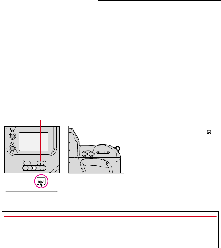
11-16
1Set the camera’s exposure mode
to M for Manual exposure
mode. Refer to “Setting
Exposure Mode” on page 8-17.
2Set the f-stop to a setting
appropriate for the ISO.
✔ISO 80: F/2 to F/32
✔ISO 200: F/2.8 to F/45
✔ISO 400: F/4 to F/64
✔ISO 800: F/5.6 to F/64
✔ISO 1600: F/8 to F/64
3Press and hold the Flash Sync
Mode button and rotate the
Main-Command Dial until
appears in the Back Status LCD
panel.
Rear-Curtain Sync cannot be
used with a studio flash system
because the correct
synchronization cannot be
attained.
IMPORTANT:
To avoid image blur, attach the camera to a tripod.
AF-ON
AF-L
AE-L
L
CSMBKT
ISO

11-17
11
Flash
Guide Numbers for Determining the Correct Aperture
Guide numbers help you determine a correct exposure or proper aperture (f/stop) when
using the SB-28D in the Manual or Repeating Flash mode.
The guide number represents the amount of light at ISO 200 for meters/feet (m/ft)
generated by the flash. With the SB-28D, you can calculate a correct aperture or desired
flash shooting distance by using the following equations and the guide number table.
Calculating the Correct Aperture
Calculating the Shooting Distance
Guide Number Table
Guide Numbers in meters/feet at ISO 200 in Manual and Repeating Flash modes.
Flash
Output
Level
Zoom-head position
18mm 20mm 24mm 28mm 35mm 50mm 70mm 85mm
1/1 (full) 25/84 28/93 42/139 45/148 51/167 59/195 68/223 71/232
1/2 18/59 20/66 30/98 32/105 36/118 42/138 48/157 50/164
1/4 12.7/42 14/46 21/69 22.5/74 25.5/84 30/98 34/112 36/118
1/8 9/30 10/33 15/49 16/53 18/59 21/69 24/79 25/82
1/16 6.4/21 7/23 10.5/35 11.3/37 12.7/42 15/49 17/56 18/59
1/32 4.5/15 5/16 7.5/25 8/26 9/30 10.5/35 12/39 12.7/42
1/64 3.2/10 3.5/11 5.3/17 5.7/19 6.4/21 7.5/25 8.5/28 9/30
M
f/stop (aperture) = Guide number
Flash shooting distance (m/ft)
flash shooting distance (m/ft) = Guide number
f/stop (aperture)

11-18
With ISO set to 200, you can locate the guide number in the table (shown on the previous
page), then use the formulas on the previous page to determine aperture or the optimal
flash shooting distance.
For example, with ISO 200, a Flash output level of 1/1 (full), a Zoom-head position of
35 mm, the guide number is 51/167. If the Flash shooting distance is 9 meters
(approximately 30 feet), the appropriate aperture is:
f/stop = 51/9 (meters) = 5.67 = approximately 5.6
f/stop = 167/30 (feet) = 5.57 = approximately 5.6
For ISO settings other than 200, multiply the guide number by the factors shown below:
For example, if the ISO in the previous example was 800 (rather than 200), the guide
number is 102 (51 x 2).
ISO Setting Multiplier
80 0.632
200 1
400 1.414
800 2
1600 2.827
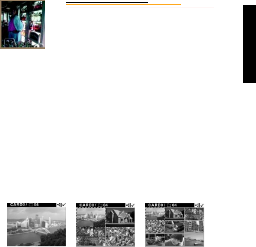
12-1
12
Camera Images
Working with
Images on the
Camera
12
The Image LCD panel allows you to view images and information about images stored on
a PC Card. You can adjust the display contrast for a better view of the images. In addition,
you can record sound files to be associated with images, and delete images to free up
space on the PC Card.
Image Review Mode
There are three modes available for viewing images on the Image LCD panel: Single,
Four, and Nine Image Review mode.
Single Image Review mode Four Image Review mode Nine Image Review mode
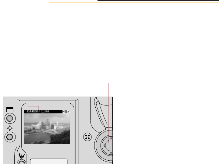
12-2
Setting the Review Mode
1Insert a PC Card. Refer to
“Inserting/Removing PC Cards”
on page 5-3.
2Press the Display button to turn
on the Image LCD panel.
3Select the Display icon, then
select Single, Four, or Nine
image Review mode. Refer to
“Navigation Techniques” on
page 2-14.
One, four, or nine images will be
displayed. Refer to “Image
Review Mode” on page 12-1.
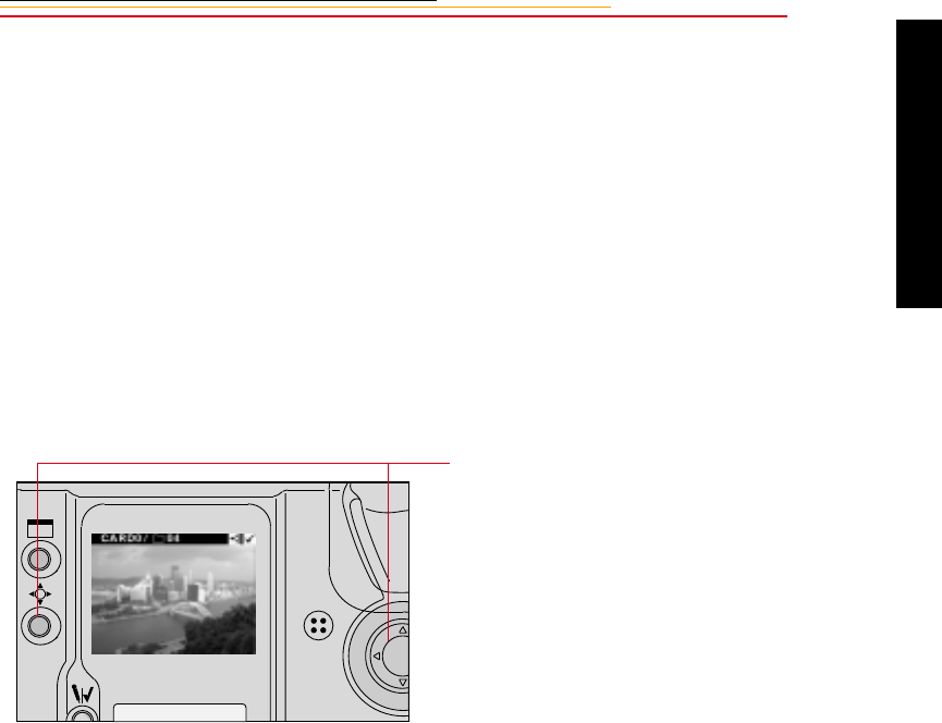
12-3
12
Camera Images
Reviewing Images
You can review any images that are stored on the PC Card, a folder at a time. (Only the
images in the currently selected folder are available for display at any one time.)
1Select a PC Card and folder (page 5-8).
2Select the Display icon, then select the Image Review mode (page 2-14).
3Adjust the contrast, if needed (page 12-6).
4Navigate through the images in the currently selected folder. (described on the next
few pages.)
Navigating in Single Image Review Mode
Navigating in Four or Nine Image Review Mode
You can navigate horizontally or vertically in Four or Nine Image Review mode.
Examples of navigation in Four Image Review mode appear on the next two pages.
Navigation works the same way in Nine Image Review mode.
Press and hold the Selector button
and press the right or left side of the
Navigate switch to scroll forward or
backward through the images in the
currently selected folder.
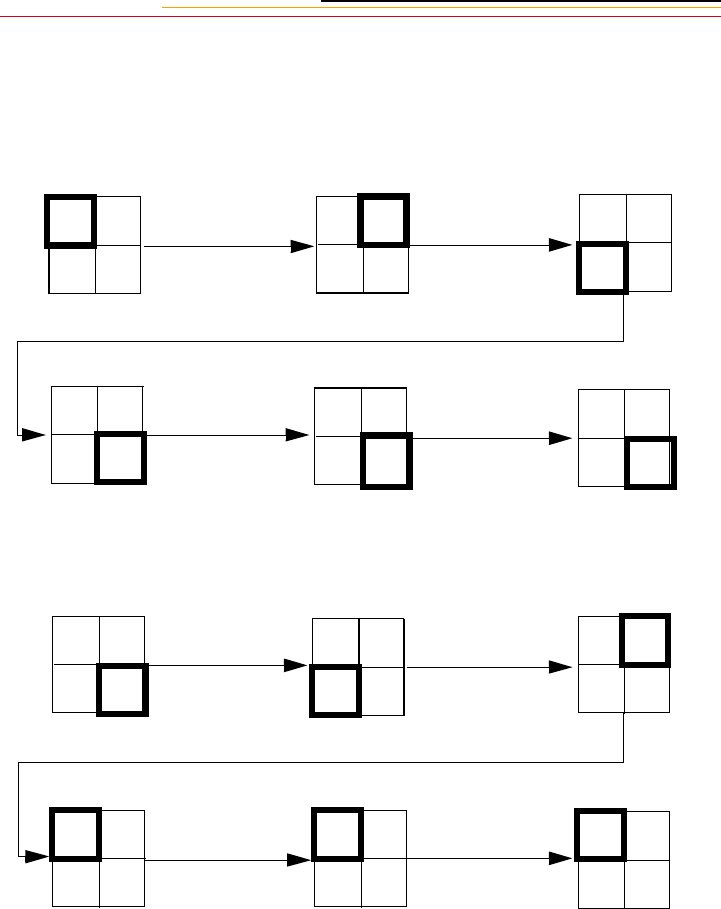
12-4
Navigating Horizontally
Press and hold the Selector button and press the right side of the Navigate switch to scroll
horizontally from the lower numbered to the higher numbered images in the currently
selected folder.
Press and hold the Selector button and press the left side of the Navigate switch to scroll
horizontally from the higher numbered to the lower numbered images in the currently
selected folder.
44 45
46 47
44 45
46 47
44 45
46 47
44 45
46 47
45 46
47 48
46 47
48 49
44 45
46 47
44 45
46 47
44 45
46 47
44 45
46 47
43 44
45 46
42 43
45
44
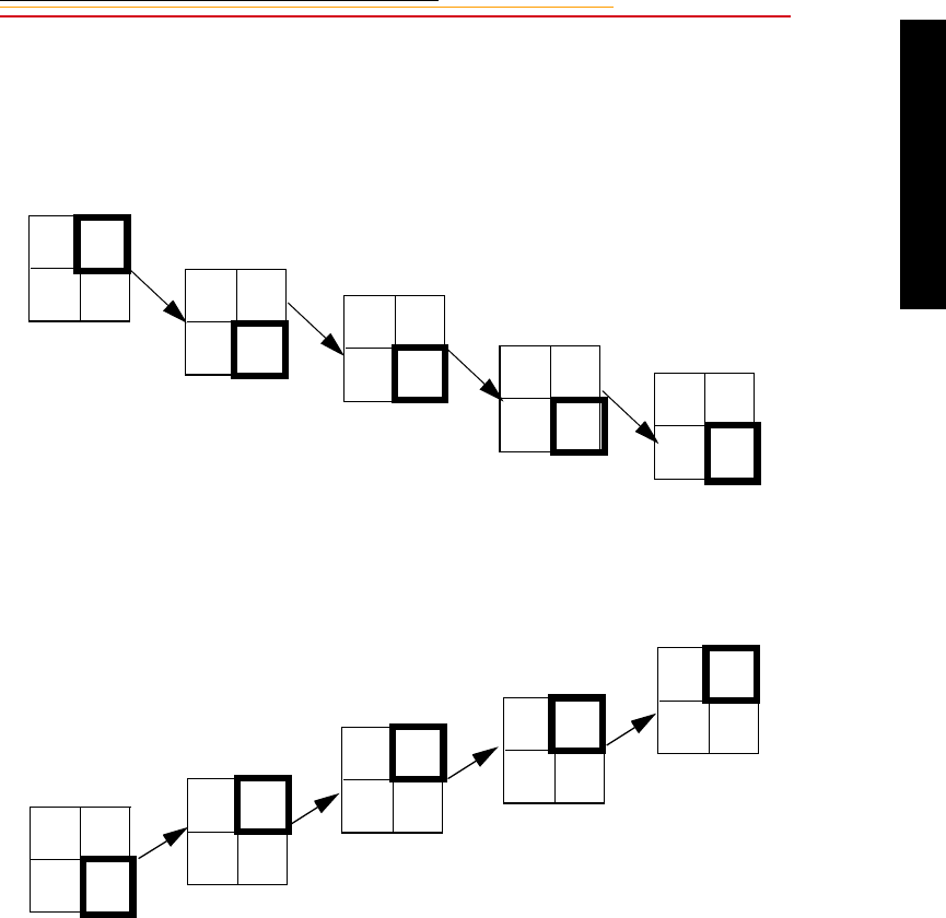
12-5
12
Camera Images
Navigating Vertically
Press and hold the Selector button and press the bottom of the Navigate switch to scroll
vertically from the lower numbered to the higher numbered images in the currently
selected folder.
Press and hold the Selector button and press the top of the Navigate switch to scroll
vertically from the higher numbered to the lower numbered images in the currently
selected folder.
42 43
44 45 42 43
44 45
44 45
46 47 48 49
50 51
46 47
48 49
48 49
50 51
48 49
50 51
46 47
48 49
44 45
46 47
42 43
44 45
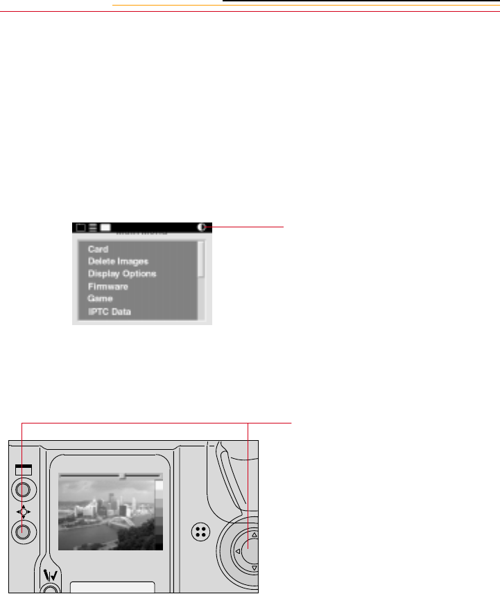
12-6
Adjusting Display Contrast
You can change the contrast to lighten or darken the images displayed on the Image LCD
panel.
☛Changing contrast does not affect the stored images, only the view of the images on
the Image LCD panel.
If you change the contrast setting, the change is maintained during Powersave and when
you turn off the camera.
1Select the Contrast icon. Refer
to “Menu Bar” on page 2-12.
A grayscale bar is displayed at
the side of the image and a
slider is displayed across the
top.
2Press and hold the Selector
button and press the right or left
side of the Navigate switch to
move the slider. Continue until
the desired contrast is achieved.
The displayed image changes to
reflect the contrast change, as
does the grayscale bar.
☛With proper contrast, the
grayscale bar runs from black
to white, with clearly defined
steps in between.
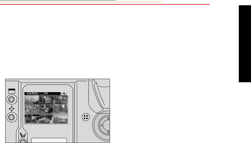
12-7
12
Camera Images
Selecting an Image
You must select an image if you want to tag it, record a sound file, or specify that it not be
deleted, as described in the next few sections. When you capture an image, that image
automatically becomes the current image. If you need a different image to be current, you
will need to select it.
1Press and hold the Selector and
navigate through the images
until the selection rectangle is
displayed over the image that
you wish to select.
2Release the Selector button.
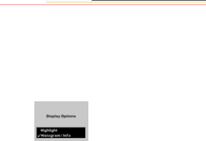
12-8
Setting Display Options
You can specify that areas of overexposure be highlighted. In addition, you can specify
that the exposure histogram and information about the image be displayed. (The histogram
is only displayed in Single Image Review mode.)
1Select the Menu icon, then
choose Main Menu from the
dropdown menu (page 2-14).
2Select Display Options from the
Main menu.
The Display Options screen
appears.
3Click an option to turn it on or
off.
If you turn Highlighting on, any
overexposed areas of the image
blink.
☛This is not necessarily a bad
thing. The highlighting
indicates areas where the light
exceeds an RGB value of 255.
To temporarily stop the blinking
of highlights, press and hold the
Selector button.

12-9
12
Camera Images
If you turned the Histogram/Info
option On, the histogram and
exposure information appears.
The image histogram shows the
range and distribution of tonal
values for an image. It displays
the number of occurrences of
each pixel code value, and can
be used to assess an image’s
brightness and contrast levels.
Pixel code values represent the
relative value of light intensities
in a scene. They range from 0
(darkest elements in a scene) to
255 (brightest elements in a
scene). For a high contrast
image, the histogram will
include almost the entire range
of pixel code values. For a low
contrast image, the histogram
will include a small range of
pixel code values.
The histogram and exposure
information are not displayed in
Four or Nine Image Review
mode.
To temporarily toggle between
the display of the Histogram and
the image, press and release the
Selector button.
Image name
Date
Time
Shutter speed
ISO setting
Aperture
Exposure mode
Exposure compensation
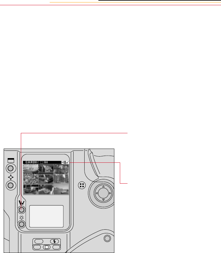
12-10
Tagging Images
You can tag one or more images then perform operations on the tagged (or untagged)
images using the camera or the DCS Host software. On the camera, you can specify that
the tagged images be processed (page 6-2), transmitted, or NOT deleted (page 12-14).
(Image transmission is described in the DCS Transmission kit which can be purchases
separately.)
In the DCS Host software you can select tagged (or untagged) images and perform a
variety of operations. Refer to the KODAK PROFESSIONAL DCS Host Software User’s
Manual on the DCS Host Software CD included with your camera.
1Select the desired review mode.
2Select an image.
3Press the Record/Tag button.
Do not hold the Record/Tag
button for more than one second
or you will activate the
microphone used for attaching
sound files to images.
A Tag icon appears above the
image at the top right of the
Menu Bar.
☛You can also tag the last image
captured until the camera
enters PowerSave mode or you
perform another operation
(regardless of whether you
have selected a Review mode).
Press the Record/Tag button.
4To remove a tag, press and
release the Record/Tag button
again.
ISO
BKT CSM
L
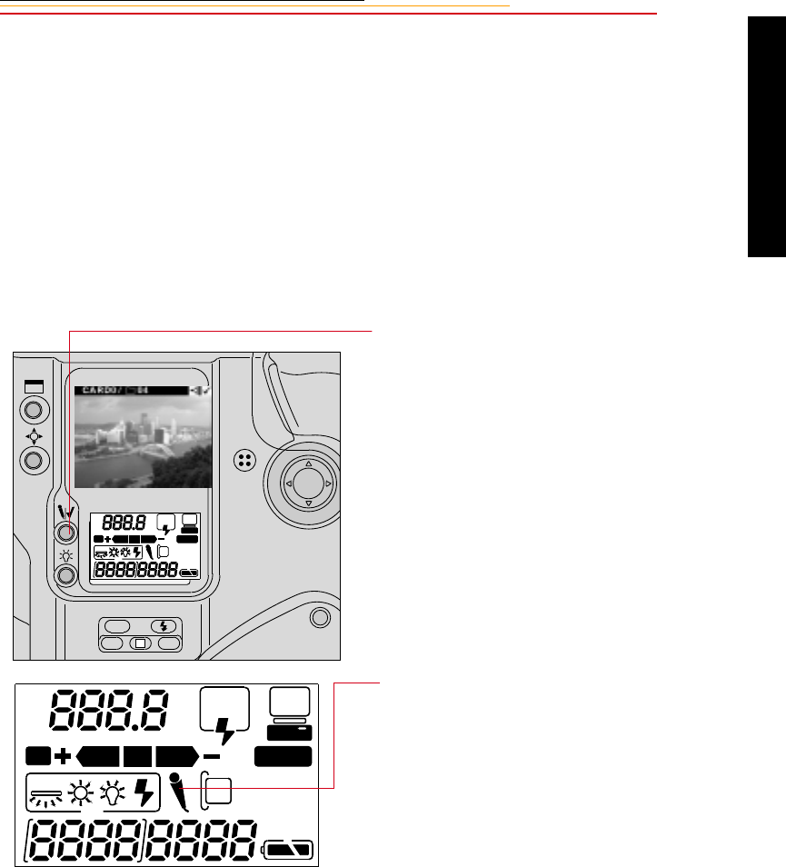
12-11
12
Camera Images
Associating Sound Files With Images
You can attach a sound file to the current image, either immediately after you capture it, or
later when you review it. If you delete the image using camera controls, or copy or delete
it using the DCS Host software, the sound file will also be copied or deleted. If you copy
or delete images without using the DCS Host software, you must also copy or delete the
sound (.WAV) files. Refer to the KODAK PROFESSIONAL DCS Host Software User’s
Manual on the DCS Host Software CD included with your camera.
1Capture an image or select the
image to which you wish to
attach a sound file.
2Press and hold the Record/Tag
button for more than one
second.
A Microphone icon in the Back
Status LCD panel indicates that
you can begin recording.
ISO
BKT CSM
L
REAR
SLOW
AUTO
ISO
BKT CUSTOM
REAR
SLOW
AUTO
ISO
BKT CUSTOM
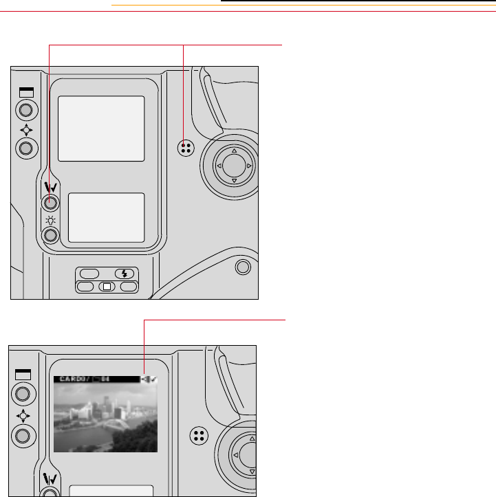
12-12
You cannot record sounds and the Microphone icon is not displayed in the Back Status
LCD panel under the following circumstances:
✔No image in the current folder
✔No PC Card in the camera
✔The PC Card in the camera is full
✔You are capturing an image or a burst of images.
☛If you record a sound file after capturing a burst of images, the file will be associated
with the last image in the burst.
3Speak into the microphone
while continuing to press the
Record/Tag button.
4Release the Record/Tag button.
The recording stops and the
Microphone icon goes away.
A Sound icon at the right of the
menu bar indicates that the
current image has an associated
sound file
ISO
BKT CSM
L
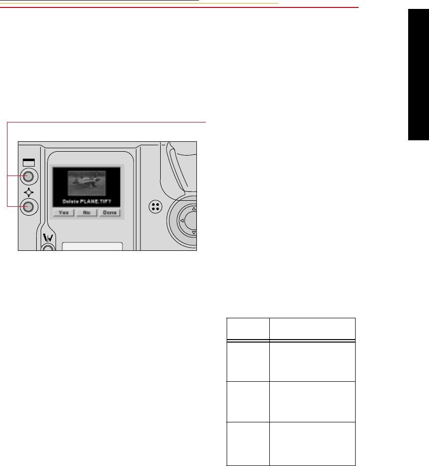
12-13
12
Camera Images
Deleting Images
You can delete one or more images from a PC Card to make space for additional images.
Any sound files associated with an image are also deleted.
Deleting a Single Image
1Press and hold the Display
button and the Selector button at
the same time.
If the Image LCD panel is off, it
will turn on.
The Delete Image screen
appears, showing the current
image (whether the Image LCD
panel was on or off).
2While continuing to hold the
Selector button, release the
Display button and use the
Navigate switch to highlight
your choice.
Choice Result
Yes The image is deleted
and the next image
is displayed
No The image is not
deleted and the next
image is displayed
Done The image is not
deleted and the
screen goes away
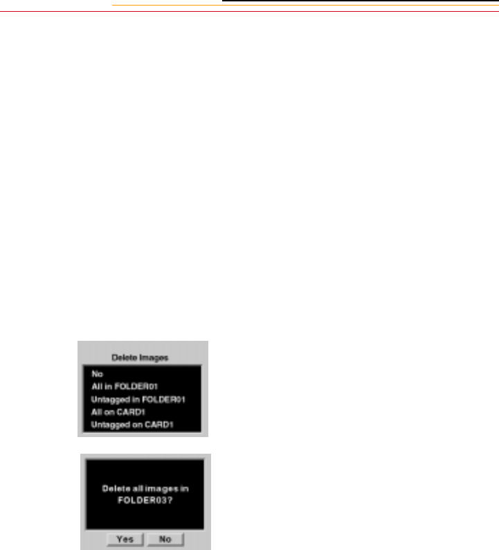
12-14
Deleting More Than One Image
You can delete all images in a folder, all untagged images in a folder, all images on a PC
Card, or all untagged images on a PC Card.
1Select a PC Card, if necessary.
2To delete all untagged images in
a folder or on a card, tag any
images that you DO NOT want to
delete. Refer to “Tagging
Images” on page 12-10.
3Select the Menu icon, then
choose Main Menu from the
dropdown menu.
4Select Delete Images from the
Main menu.
The Delete Images menu
appears, displaying choices for
the active PC Card.
5Select your choice.
A confirmation screen appears.
6Select Yes or No.
If you chose Yes, the images that
you specified are deleted. (If
you chose one of the tagged
image options, images that you
tagged are NOT deleted.)
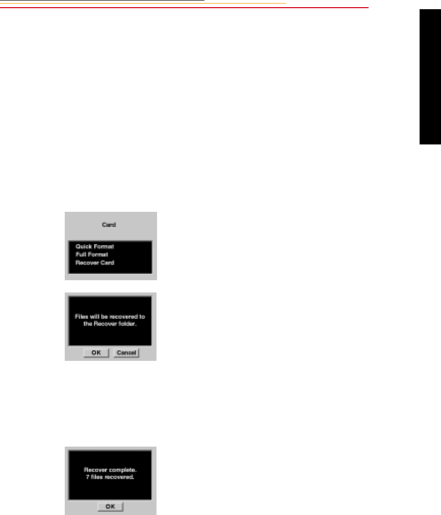
12-15
12
Camera Images
Recovering Deleted Images
You can recover images that were previously deleted from a PC Card, if they have not
been overwritten. Only images that were written to a PC Card by a DCS 600 Series
camera can be recovered.
For the Recover function to work, the PC Card must have been formatted on the camera.
(The Recover function will not work for a card “out of the box” or formatted using the
DCS Host software.)
1Select the Menu icon, then
choose Main Menu.
2Choose Card from the Main
menu.
The Card menu appears.
3Choose Recover Card.
A confirmation screen appears.
A Recover folder is created on
the PC Card when you recover
images.
4Click OK.
☛You cannot capture images to
the Recover folder. If you
attempt to do so, the image is
saved to the default folder (set
in Properties) and an
appropriate message appears.
A recovery complete screen
appears, telling you how many
files were recovered.
5Click OK.
6Copy images from the PC Card
and format the card before using
it to capture more images.
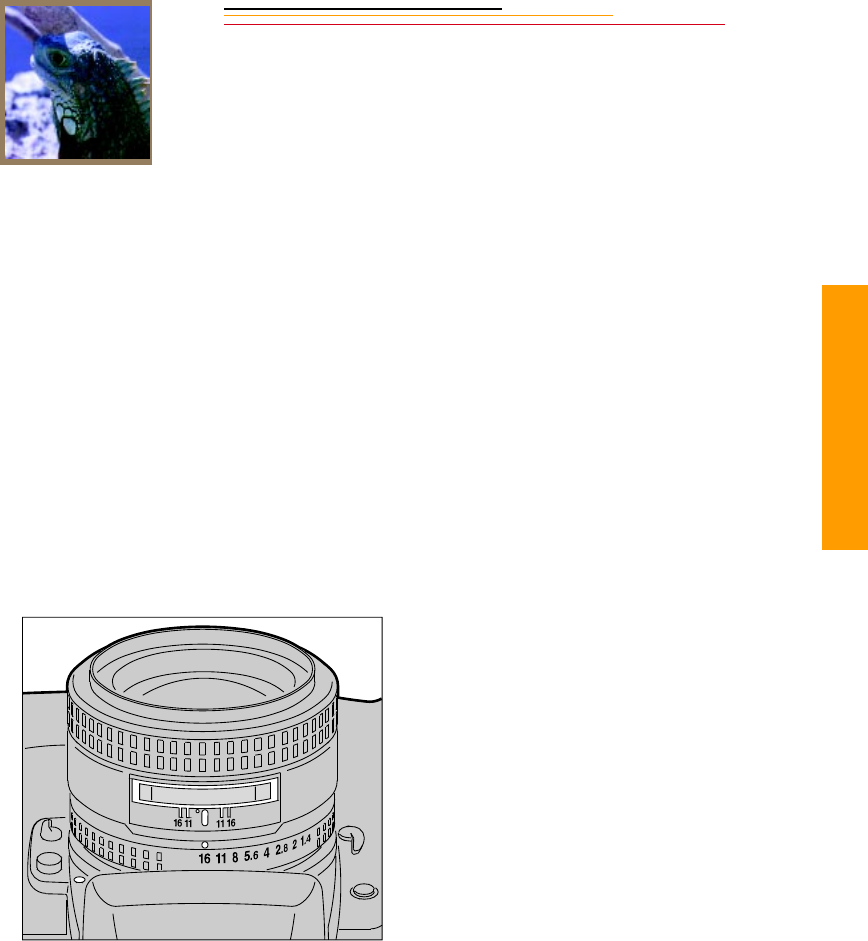
INSERT
PHOTO
HERE
13-1
13
Advanced
Advanced Operation
13
This chapter explains advanced photographic techniques and applications such as
Exposure mode, Flexible program, Focus lock, AE/AF lock, and Exposure compensation.
It also explains the use of the Self timer, long term exposure, and Custom Settings.
Capturing Images in Each Exposure Mode
Shutter-Priority Auto Exposure Mode
☛This operation can be performed only with lenses having a built-in CPU. Refer to
Appendix C for more information.
☛If “bulb” is set on the camera, selecting the Shutter-Priority Auto Exposure mode
will cause buLb to blink—a warning that the “bulb” setting cannot be used in
Shutter-Priority mode.
1Set the lens to its minimum
aperture. Refer to “Setting the
Lens to the Minimum Aperture”
on page 2-22.
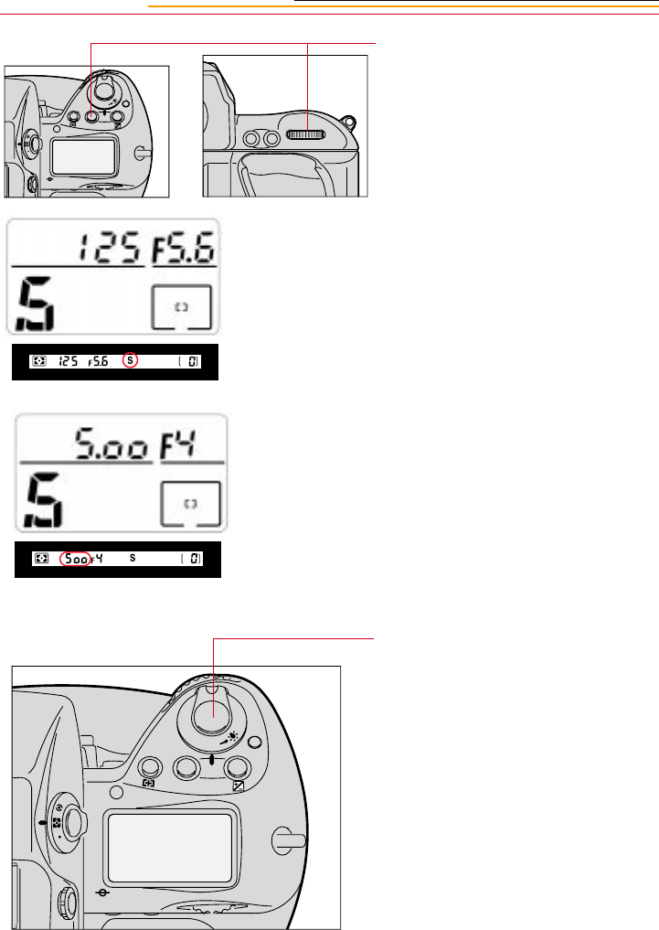
13-2
2Press and hold the MODE button
and rotate the Main-Command
dial until S appears in the Top
Status LCD panel and
viewfinder.
3Remove your finger from the
MODE button, and rotate the
Main-Command dial to select
the desired shutter speed.
☛Shutter speed is divided into
1/3 stop increments from 30
seconds to 1/8000 second, and
the flash sync speed is 1/250
second (x25o).
4Look inside the viewfinder,
compose, and lightly press the
Shutter Release button.
F
N
F
O
O
MODE
AF-ON
AF-L
AE-L
F
N
F
O
O
MODE
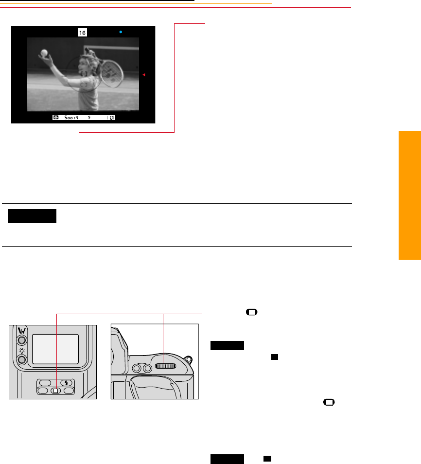
13-3
13
Advanced
Locking Shutter Speed
You can lock the selected shutter speed to avoid accidental changes of settings.
5Confirm the automatically set
aperture value.
6Fully depress the Shutter
Release button to capture the
image.
You can change the direction that the Main-Command dial must be
turned to increase/decrease shutter speed using Custom Setting #6.
Refer to “Custom Settings” on page 13-32.
Press the (Shutter Lock) button
and rotate the Main-Command dial.
appears in the Top Status
LCD panel and appears in the
viewfinder above the shutter speed
indications.
To release the lock, press the
button and rotate the Main-
Command dial again, or select
another exposure mode.
and disappear.
CUSTOM
AF-ON
AF-L
AE-L
L
CSMBKT
ISO
L
LOCK
L
L
LOCK L
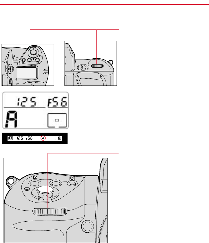
13-4
Aperture-Priority Auto Exposure Mode
1Press and hold the MODE button
and rotate the Main-Command
dial until A appears in the Top
Status LCD panel and in the
viewfinder.
2Remove your finger from the
MODE button, and rotate the
Sub-Command dial to select the
desired aperture.
3Set the lens to its minimum
aperture. Refer to “Setting the
Lens to the Minimum Aperture”
on page 2-22.
F
N
F
O
O
MODE
AF-ON
AF-L
AE-L
MODE
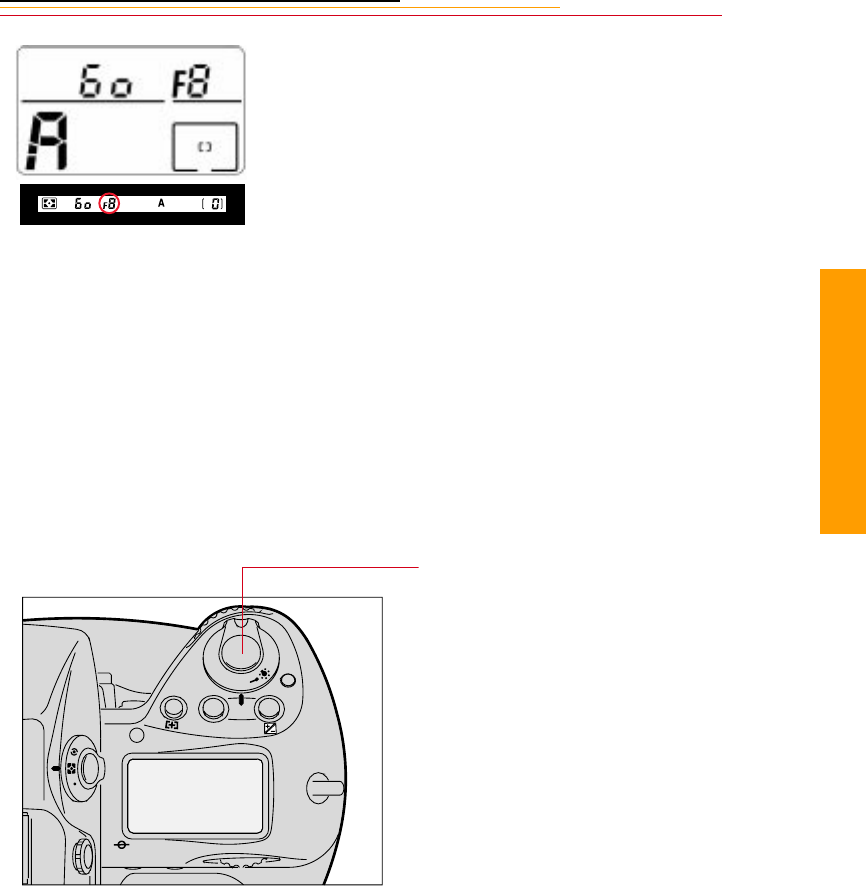
13-5
13
Advanced
The aperture setting is indicated
in the Top Status LCD panel and
viewfinder.
The aperture indication changes
in 1/3 stop increments between
the lens’ maximum and
minimum apertures.
You can also set the aperture by
rotating the lens aperture ring. In
this case, F-- blinks in the
viewfinder and in the Top Status
LCD panel and you can only
confirm the aperture setting
through the aperture direct
readout in the viewfinder.
To select the minimum aperture
with the lens aperture ring, you
must also set the minimum
aperture with the Sub-Command
dial.
4Look inside the viewfinder.
Compose, and lightly press the
Shutter Release button.
F
N
F
O
O
MODE
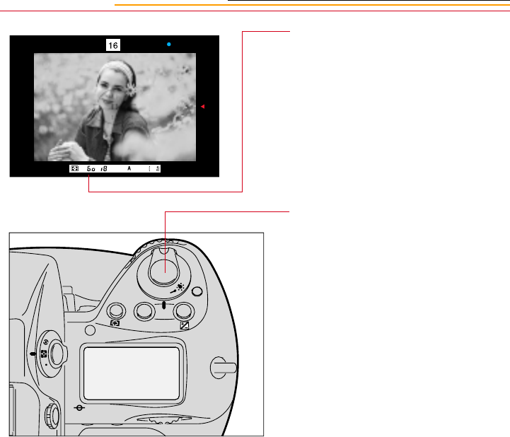
13-6
5Confirm the automatically set
shutter speed.
6Fully depress the Shutter
Release button to capture an
image.
F
N
F
O
O
MODE
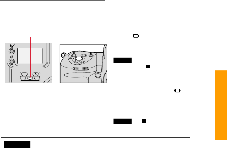
13-7
13
Advanced
Locking the Aperture
You can lock the selected aperture to avoid accidental changes of settings.
Press the (Aperture Lock)
button and rotate the Sub-Command
dial.
appears in the Top Status
LCD panel and appears in the
viewfinder above the aperture
indications.
To release the lock, press the
button and rotate the Sub-Command
dial again, or select another
exposure mode.
and disappear.
You can use Custom Setting #22 to set the aperture so that it will not
change when you rotate the Sub-Command Dial. Set the aperture by
rotating the lens’ aperture ring in this case. Refer to “Custom
Settings” on page 13-32.
L
CSMBKT
ISO
MODE
L
LOCK
L
L
LOCK L
CUSTOM
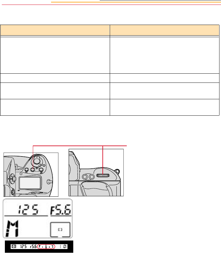
13-8
Different Procedures for Different Lenses
Manual Exposure Mode
Lens Type Procedure
Lens without a CPU F-- blinks instead of the aperture value in
the Top Status LCD panel and viewfinder.
Set the aperture manually with the lens
aperture ring.
AI-type lens Confirm the aperture value on lens barrel.
Lens having fixed aperture, such as a
Reflex-Nikkor lenses
Aperture cannot be changed.
Lens without an auto diaphragm such as a
PC-Nikkor lenses
Switch to Manual exposure mode. See
below.
1Press and hold the MODE button
and rotate the Main-Command
dial until M appears in the Top
Status LCD panel and the
electronic analog display
appears in the viewfinder.
F
N
F
O
O
MODE
AF-ON
AF-L
AE-L
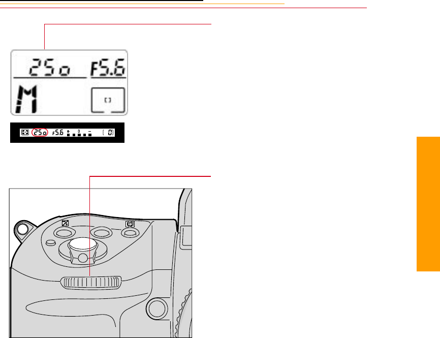
13-9
13
Advanced
2Remove your finger from the
MODE button, and set the shutter
speed by rotating the Main
Command dial.
Shutter speed can be set in 1/3
stop increments.
In Manual exposure mode, you
can set the shutter speed to buLb
for extended time exposures.
Refer to “Long Time Exposure”
on page 13-30.
3Rotate the Sub-Command dial to
set the aperture. (The lens
aperture is set to its minimum
position.)
Aperture is divided into 1/3 step
increments from the maximum
to the minimum apertures.
You can also set the aperture by
rotating the lens aperture ring. In
this case, F-- blinks in the
viewfinder and Top Status LCD
panel, and the aperture can be
confirmed only through the
viewfinder’s aperture direct
readout. When setting the
minimum aperture using the lens
aperture ring, be sure to set the
aperture to the minimum with
the Sub-Command Dial first.
MODE
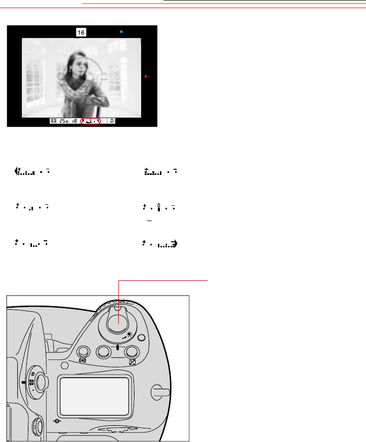
13-10
4Look into the viewfinder,
compose the scene, and lightly
press the Shutter Release button.
5Adjust the aperture and/or
shutter speed until the electronic
analog exposure display shows
“0” or the desired exposure
value.
6Fully depress the Shutter
Release button to capture an
image.
Examples
Over +2EV
+ 1/3EV
- 1/3EV
+2EV
+OEV
Below -2EV
F
N
F
O
O
MODE
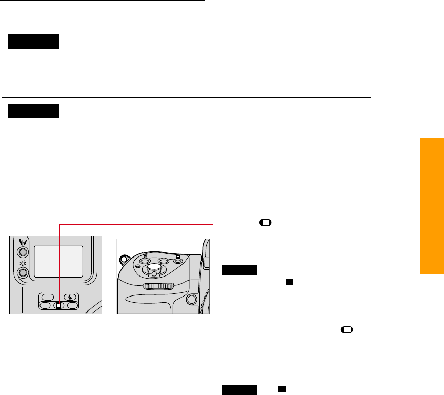
13-11
13
Advanced
Locking Shutter Speed/Aperture
You can lock the selected shutter speed/aperture to avoid accidentally changing a setting.
You can use Custom Setting #19 to change the lowest shutter speed
from 30 seconds to as much as 30 minutes. Refer to “Custom
Settings” on page 13-32.
You can use Custom Setting #22 to set the aperture so that it will not
change when you rotate the Sub-Command Dial. Set the aperture by
rotating the lens aperture ring in this case. Refer to “Custom
Settings” on page 13-32.
Press the (Shutter Speed/
Aperture Lock) button and rotate
the Main- or Sub-Command dial.
appears in the Top Status
LCD panel and appears in the
viewfinder above the shutter speed/
aperture indications.
To release the lock, press the
button and rotate the Main- or Sub-
Command dial, or select another
exposure mode.
and disappear.
CUSTOM
CUSTOM
L
CSMBKT
ISO
MODE
L
LOCK
L
L
LOCK L

13-12
Different Procedures for Different Lenses
Lens Type Procedure
Lenses without a CPU ☛F-- blinks instead of the aperture
value in the Top Status LCD panel
and viewfinder.
Set the aperture manually with lens
aperture ring.
Lens having fixed aperture, such as a
Reflex-Nikkor lenses
Aperture cannot be changed. Adjust
exposure by changing the shutter speed.
Lenses without an auto diaphragm such as
a PC-Nikkor lens
Lens is stopped down when a smaller
aperture (larger f-stop) is selected. Focus
manually with the lens at the maximum
aperture.
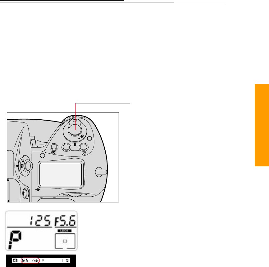
13-13
13
Advanced
Flexible Program
Flexible Program changes the shutter speed/aperture combination in Programmed Auto
Exposure mode. Flexible Program lets you temporarily change an automatically set
shutter speed/aperture combination in 1/3 step increments, while maintaining consistent
exposure.
1Select Programmed Auto
Exposure mode (P). Refer to
“Setting Exposure Mode” on
page 8-17.
2Lightly press the Shutter
Release button.
The shutter speed and aperture
appear in the Top Status LCD
panel and viewfinder.
F
N
F
O
O
MODE
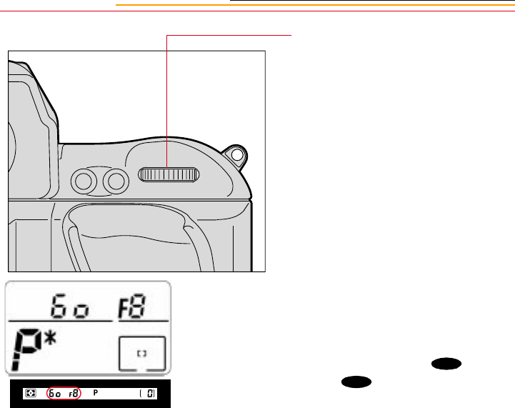
13-14
Focus Lock For Off-center Subjects
In Single Servo AF mode, focus remains locked as long as the Shutter Release button is
kept lightly pressed. Focus can be locked in any of the five focus areas.
☛With a moving subject, focus cannot be locked.
☛In Continuous Servo AF mode, lock the focus using the AE-L/AF-L button. Refer to
“AE/AF Lock” on page 13-16. In this case, both exposure and focus are
simultaneously locked.
3Rotate the Main-Command dial
until the desired shutter speed or
aperture value appears in the
viewfinder and Top Status LCD
panel. The Flexible Program
indicator (P*) appears,
indicating that the program has
been shifted or changed.
The shifted program is
maintained unless you rotate the
Main-Command dial to the
previous shutter speed/aperture.
Flexible Program is canceled when
you do one of the following:
✔Switch to a different
Exposure mode
✔Activate Two-Button Reset
by pressing the and
buttons
simultaneously
✔Turn the power switch Off.
AF-ON
AF-L
AE-L
BKT
CSM
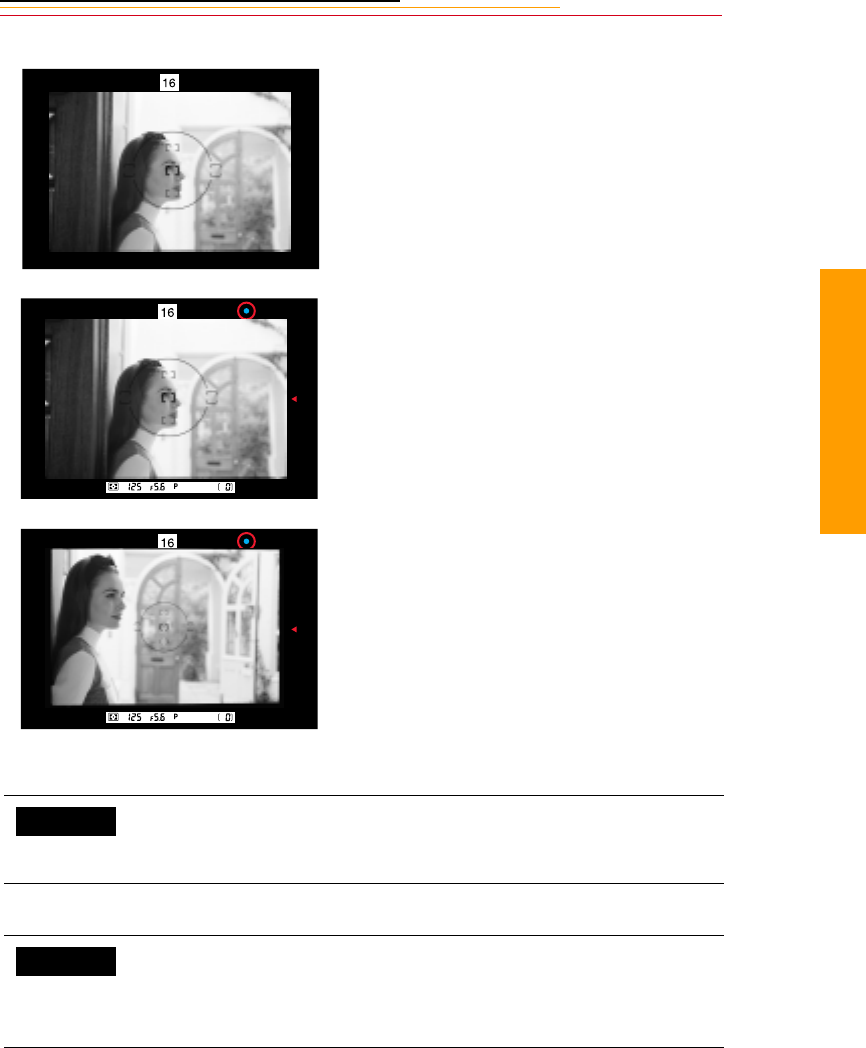
13-15
13
Advanced
1Position the focus brackets on
the subject and lightly press the
Shutter Release button to start
the autofocus operation.
2Confirm that the green in-focus
indicator • appears in the
viewfinder.
3Keeping the Shutter Release
button lightly pressed,
recompose, then fully depress
the Shutter Release button to
capture the image.
You can use Custom Setting #7 to set both exposure and focus to lock
simultaneously when you lightly press the Shutter Release button.
Refer to “Custom Settings” on page 13-32.
You can use Custom Setting #4 to deactivate autofocus and keep the
lens from focusing when you lightly press the Shutter Release button.
In this case, focus can be locked by keeping the AF start button
pressed. Refer to “Custom Settings” on page 13-32.
CUSTOM
CUSTOM

13-16
☛If a subject is covered by one of the five focus brackets, you can also capture an
image of an off-center subject by shifting the focus to the relevant focus area without
changing the composition. Refer to “Selecting the Focus Area” on page 9-1.
AE/AF Lock
You can simultaneously lock both exposure and focus by pressing the AE-L/AF-L button.
AE/AF lock can be used with both Single Area AF or Dynamic AF operation, and with all
metering systems used for automatic exposure control functions.
✔You can achieve correct exposure using Single Servo AF, when Single Area AF
mode and Spot Metering are selected, by choosing a focus area that corresponds to
your picture composition.
✔You can change the aperture in Aperture-Priority Auto Exposure mode and shutter
speed in Shutter-Priority Auto Exposure mode while pressing the AE-L/AF-L
button.
✔You cannot change the metering system while pressing the AE-L/AF-L button.
✔You can lock only the focus in Single Servo AF by lightly pressing the Shutter
Release button and recomposing. Refer to “Focus Lock For Off-center Subjects”
on page 13-14.
✔You can lock only the exposure by pressing the AE-L/AF-L button in Manual
Focus mode.
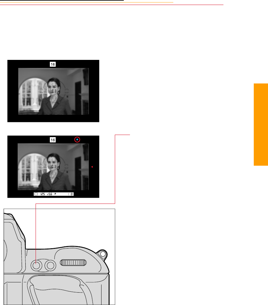
13-17
13
Advanced
About AE Lock
When you are using Auto Exposure mode, use AE lock to control exposure based on the
brightness of a specific area within a scene. Center-Weighted (page 8-11) or Spot
Metering (page 8-12) is recommended when using AE lock.
1Position the focus brackets on
the subject.
2Lightly press and hold the
Shutter Release button to start
the autofocus operation.
3Keeping the Shutter Release
button lightly pressed, confirm
that the in-focus indicator •
appears in the viewfinder. Then
press and hold the AE-L/AF-L
button to lock focus and
exposure.
AF-ON
AF-L
AE-L
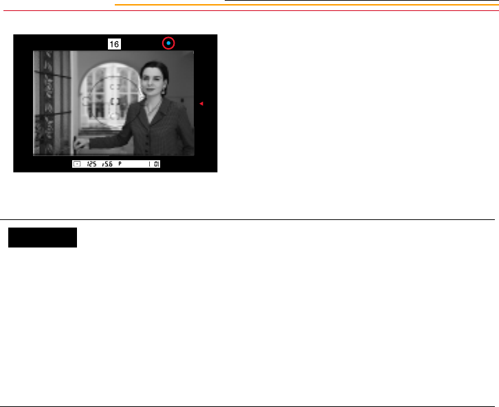
13-18
4Keep pressing the AE-L/AF-L
button, recompose the scene,
then fully depress the Shutter
Release button to capture the
image.
You can use Custom Setting #21 to set the AE-L/AF-L button to lock
either focus or exposure (not both, as with the default).
You can use Custom Setting #5 to set the AE-L/AF-L button to lock
the camera’s controlled shutter speed and aperture instead of the
detected exposure value.Refer to “Custom Settings” on page 13-32.
You can use Custom Setting #4 to deactivate autofocus and keep the
lens from focusing when you lightly press the Shutter Release button.
In this case, focus can be locked by keeping the AF start button
pressed. Refer to “Custom Settings” on page 13-32.
CUSTOM

13-19
13
Advanced
Exposure Compensation
Exposure compensation is a photographic technique that enables you to vary the final
exposure settings from those measured by the camera’s light meter. 3D Color Matrix
Metering employs methods of exposure calculation that automatically apply exposure
compensation, depending upon scene brightness, contrast, focused subject’s distance and
color distribution of the entire frame. As a result, your subject, whether it is centered in the
viewfinder or not, is given corrected exposure in most lighting situations.
It is not recommended that you use manually or automatically applied exposure
compensation when using 3D Color Matrix Metering. If you identify an extreme condition
under which Matrix may have some difficulty, such as a severely backlit scene or one with
extremes of contrast, it is recommended that you use your camera’s other built-in meters,
Center-Weighted or Spot.
Ultimately, only you know what the subject or scene requires in terms of exposure
measurement. That’s why your camera incorporates three meters plus a variety of
exposure compensation systems. Your creativity is always the final deciding and
controlling factor. To use the various exposure compensation functions, refer to the
following:
✔Using the AE-L/AF-L (Auto Exposure/Autofocus Lock) button (page 13-16)
✔Obtaining a meter reading for a subject in Manual Exposure mode (page 8-16)
✔Using the Exposure Compensation button (page 13-22)
✔Using Auto Exposure/Flash Exposure bracketing (page 13-24)
Results will vary, depending on conditions, so you will want to experiment with each
method.
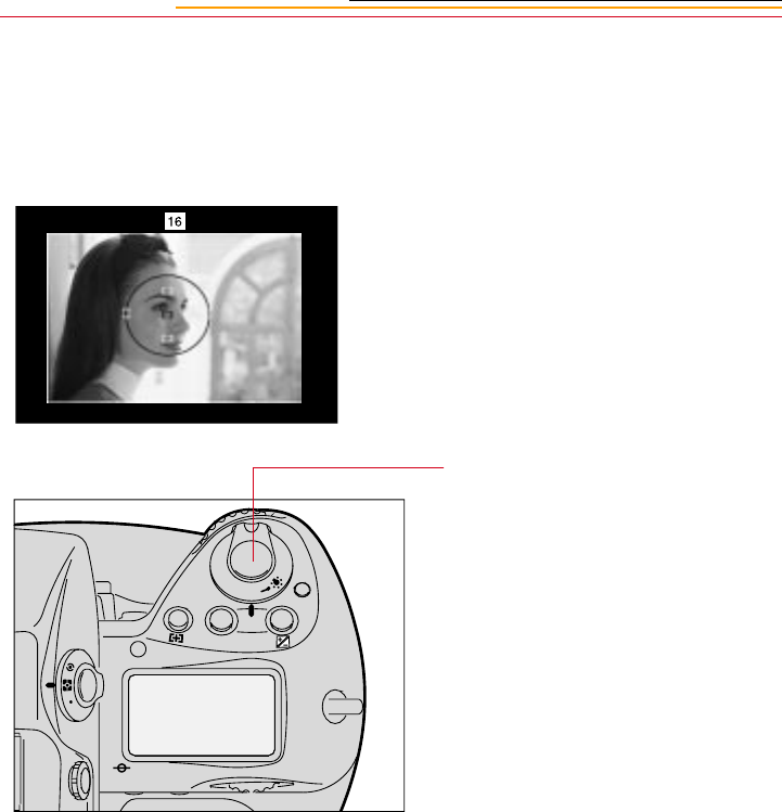
13-20
Obtaining the Meter Reading in Manual Exposure Mode
If you are using Manual Exposure mode and want to set an exposure for a specific
brightness value within the scene, switch the metering system to Center-Weighted or Spot
and use the following method.
1Center the main subject inside
the viewfinder and/or move in
closer until the reference circle
for Center-Weighted Metering
or Spot Metering is fully
covered by the subject.
2Lightly press the Shutter
Release button.
F
N
F
O
O
MODE
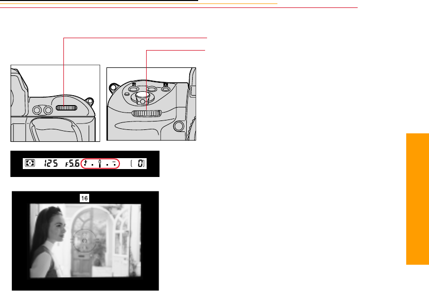
13-21
13
Advanced
☛If you are using Single Servo AF mode and recomposing the picture could change
subject-to-camera distance, refocus by briefly removing your finger from the Shutter
Release button then lightly pressing again.
☛Continuous Servo AF is not recommended if the subject becomes off-center after
recomposing.
3Adjust the shutter speed and
aperture by rotating the Main-
and/or Sub-Command dials until
the electronic analog exposure
display shows the desired
exposure.
4Recompose the picture and
capture the image.
AF-ON
AF-L
AE-L
MODE
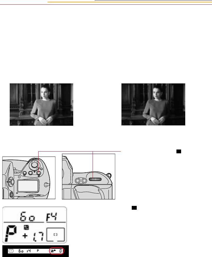
13-22
Exposure Compensation Function
To modify exposure control (from the ISO standard), use the exposure compensation
button. Compensation can be applied from –5EV to +5EV in 1/3 EV steps. After capturing
your images, be sure to reset the compensation to “0” to resume normal operation.
☛If Auto Exposure/Flash Exposure bracketing is also set, exposure compensation will
be the combined compensation values.
1Press and hold the (Exposure
Compensation) button and rotate
the Main-Command dial to set
the desired compensation value.
and the compensated value
appear in the Top Status LCD
panel and viewfinder and
remain on in the Top Status LCD
panel until reset.
☛Once set, exposure
compensation remains fixed
until reset.
Without Compensation With Compensation
F
N
F
O
O
MODE
AF-ON
AF-L
AE-L
+/-
+/-

13-23
13
Advanced
When you remove your finger
from the button, the
symbol in the viewfinder stays
on to indicate that exposure
compensation is on, but the
compensation value disappears.
To display the compensation
value, press the button again.
2After you have captured the
desired images, reset the amount
of compensation to “0.0” to
resume normal operation.
+/- +/-
+/-
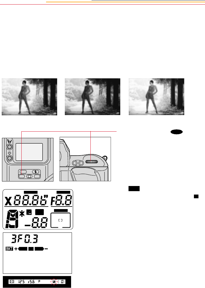
13-24
Auto Exposure/Flash Exposure Bracketing
In situations where you might find it difficult to obtain a proper exposure, Auto Exposure/
Flash Exposure bracketing lets you shoot the same subject at two or three different
exposures, with a variable exposure compensation degree of 0.3 EV, 0.7 EV or 1 EV.
If you set a compensation degree of 1 EV in a three-step bracket, for example, you will
capture three images, the first shot having no compensation, the second shot having a –1
EV compensation, and the third shot having a compensation of +1 EV.
1Press and hold the (Auto
Exposure/Flash Exposure
bracketing) button and rotate the
Main-Command dial to select
Auto Exposure/Flash Exposure
bracketing mode.
appears in the Top and
Rear Status LCD panels and
blinks in the Top Status LCD
panel and viewfinder.
L
CSMBKT
ISO
AF-ON
AF-L
AE-L
BKT
+
LOCK
LOCK
LOCK
BKT
+
BKT
+/-
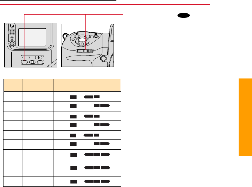
13-25
13
Advanced
2While pressing the button,
rotate the Sub-Command dial to
select the desired number of
shots and the compensation
value from one of those shown
in the table below.
MODE
L
CSMBKT
ISO
BKT
# Shots Compensated
EV value Back Status LCD panel
Two 0 and +1/3 2F0.3
Two 0 and -1/3 2F0.3
Two 0 and +2/3 2F0.7
Two 0 and -2/3 2F0.7
Two 0 and +1 2F1.0
Two 0 and -1 2F1.0
Three 0, -1/3 and
+1/3 (default) 3F0.3
Three 0, -2/3 and
+2/3 3F0.7
Three 0, -1, and +1 3F1.0
+
BKT
–
BKT
+
BKT
–
BKT
+
BKT
–
BKT
+ –
BKT
+ –
BKT
+ –
BKT
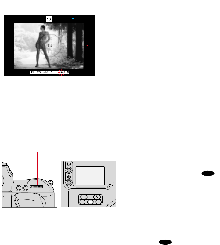
13-26
3Compose the picture, confirm
the focus and exposure, then
fully depress the Shutter Release
button.
4With the Drive mode at Single-
frame shooting (S), fully depress
the Shutter Release button the
set number of times.
With the Drive mode at
continuous shooting (CH, CL or
CS), fully depress the Shutter
Release button and hold it in
until the set number of images
have been captured and Drive
mode stops automatically.
Refer to “Choosing a Drive
Mode” on page 10-10.
5After the set number of images
have been captured, cancel Auto
Exposure/Flash Exposure
bracketing by pressing the
button and rotating the Main-
Command dial.
BKT disappears from the Top
Status and Back Status LCD
panels. The number of shots and
the compensation value
disappear from the LCD panels
when you remove your finger
from the button.
☛The set number of shots and
the compensation value
remain unchanged after Auto
Exposure/Flash Exposure
bracketing is canceled.
AF-ON
AF-L
AE-L
L
CSMBKT
ISO
BKT
BKT

13-27
13
Advanced
In Auto Exposure/Flash Exposure bracketing, the following are varied:
✔Shutter speed and aperture in Programmed Auto mode
✔Aperture in Shutter-Priority Auto mode
✔Shutter speed in Aperture-Priority Auto mode and Manual Exposure mode
✔Flash output level with a dedicated NIKON Speedlight.
If the exposure compensation function is also set, bracketing will be combined with the
exposure compensation values.
Bracketing with varying flash output levels can be performed at the buLb setting.
Bracketing is performed one frame at a time when the self-timer is set.
When a prolonged shutter speed (slower than 40 seconds) is selected with a Custom
Setting, shutter speed is not varied in bracketing.
When flash sync speed is selected in Manual Exposure mode, shutter speed is not varied in
bracketing.
In Auto Exposure/Flash Exposure bracketing mode, you can set
Custom Setting #3 to start shooting with negative compensation, no
compensation and positive compensation in that order. Refer to
“Custom Settings” on page 13-32.
You can perform only Auto Exposure bracketing or Flash Exposure
bracketing using Custom Setting #24. Refer to “Custom Settings” on
page 13-32.
In Manual Exposure mode, various factors (flash output level, shutter
speed, aperture or shutter speed/aperture combination) within the
bracketing operation can be changed using Custom Setting #17.
Refer to “Custom Settings” on page 13-32.
CUSTOM
CUSTOM
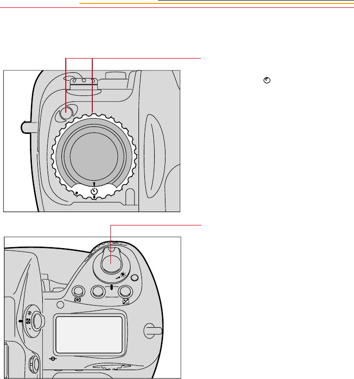
13-28
Self-Timer
1While pressing the Lock release,
set the Drive mode/Self-timer
selector to (self-timer)
position.
2Compose the picture. Lightly
press the Shutter Release button,
and confirm focus and exposure.
Refer to “Selecting the Focus
Area” on page 9-1 and “Setting
Exposure Mode” on page 8-17.
C
S
F
N
F
O
O
MODE
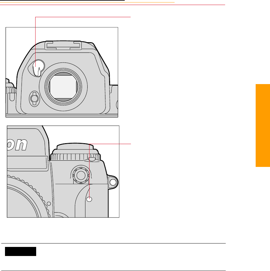
13-29
13
Advanced
In Single Servo AF with Focus-Priority, the self-timer operates only when the green
in-focus indicator • appears in the viewfinder. Once the self-timer starts, the shutter will be
released even if the subject is out of focus at the time of shutter release.
When you select buLb the shutter speed automatically sets to 1/250 second.
3With all auto exposure modes,
close the eyepiece shutter before
starting the self-timer to prevent
stray light from entering the
viewfinder and affecting the
exposure.
4Fully depress the Shutter
Release button.
The Self-timer LED starts
blinking and the shutter will be
released after 10 seconds.
During the final two seconds,
the LED stays on, warning you
to get ready to capture the
image.
☛To cancel the self-timer
operation, turn the Drive
mode/Self-timer selector to
another position.
You can use Custom Setting #16 to change the self-timer duration to
any interval from 2 to 60 seconds. Refer to “Custom Settings” on
page 13-32.
CUSTOM
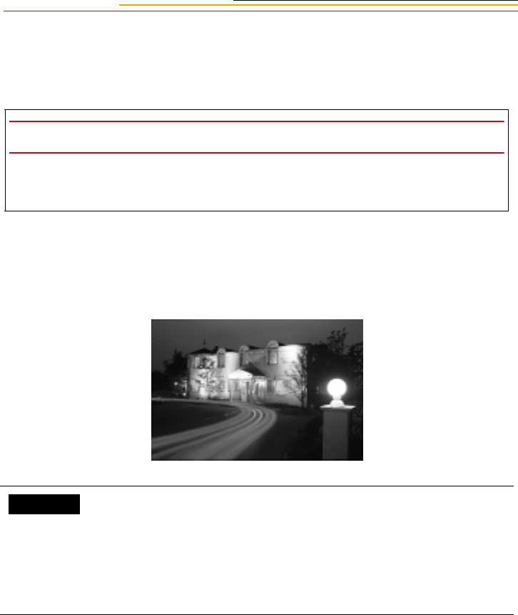
13-30
Long Time Exposure
At buLb setting, the shutter stays open as long as the Shutter Release button remains
depressed.
Use a tripod to avoid camera shake which may blur the image. Use of remote control
accessories, such as the Nikon Remote Cord MC-20, MC-30, or Modulite Remote Control
Set ML-3 is also recommended.
The duration of an exposure may depend on the condition of the batteries.
At low temperatures, batteries weaken and continuous shooting time shortens. Keep the
camera close to your body in cold conditions.
IMPORTANT:
Long exposures may add noise and produce a less desirable image. For quality
purposes, single image exposure of more than .5 second is not recommended.
You can use Custom Setting #19 to change Long Time Exposures
from 40 seconds to 30 minutes. Refer to “Custom Settings” on page
13-32.
You can set the Alert LED to blink during Long Time Exposure
using Custom Setting #11. Refer to “Custom Settings” on page 13-
32.
CUSTOM
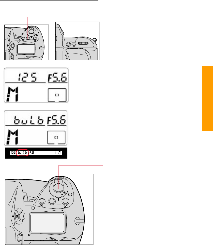
13-31
13
Advanced
1Press and hold the MODE
button and rotate the Main-
Command dial to select M for
Manual Exposure mode.
M appears in the Top Status
LCD panel.
2Remove your finger from the
MODE button and rotate the
Main-Command dial until buLb
(Bulb exposure) appears in the
Top Status LCD panel and
viewfinder.
3Fully depress the Shutter
Release button. (Hold the
Shutter Release button as long
as desired.)
To close the shutter, remove
your finger from the Shutter
Release button.
F
N
F
O
O
MODE
AF-ON
AF-L
AE-L
F
N
F
O
O
MODE
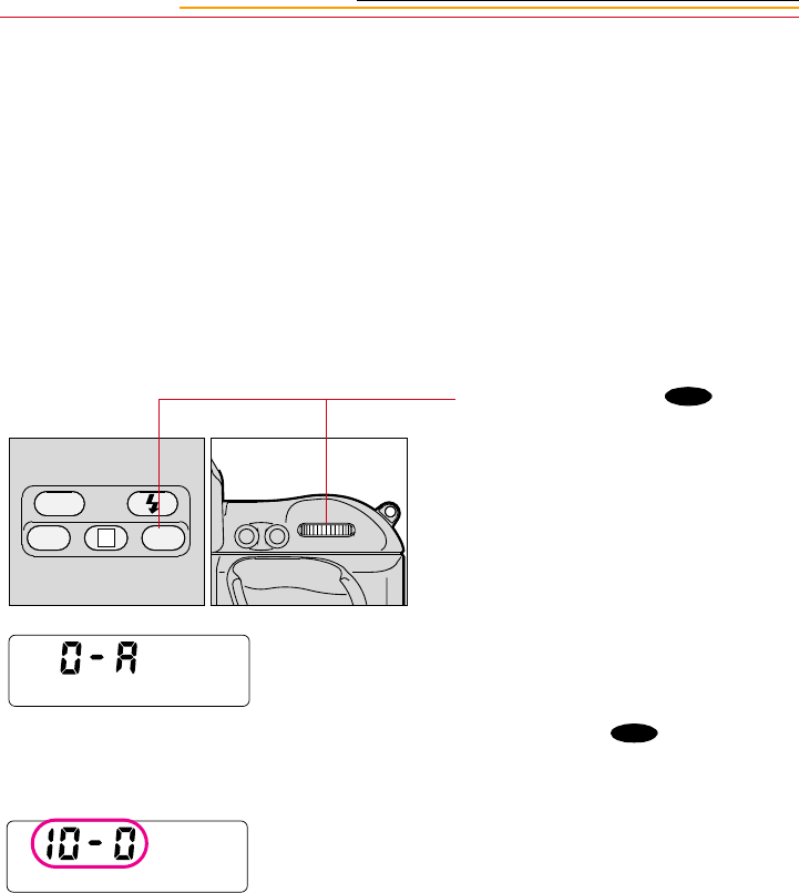
13-32
Custom Settings
You can use the Custom Setting feature to create a combination of functions that are
different from the factory settings. Use the method described below or the Custom
Settings menu, available through Properties (page 4-7)
☛In general, the Custom Settings menu is easier to use, since the settings are labeled.
Making a Custom Setting
To make a custom setting, select a custom function, then select the option for the custom
function.
1Press and hold the
(Custom Setting Menu) button
and rotate the Main-Command
dial to Select Custom Setting
mode.
2Keeping the button
pressed, rotate the Main-
Command dial further to select
the desired function number.
The number appears in the Back
Status LCD panel.
AF-L
AE-L AF-ON
BKT
ISO
L
CSM
CSM
CSM
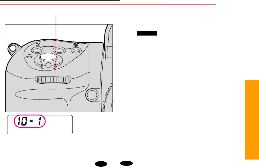
13-33
13
Advanced
Reset Factory Settings
To reset all Custom Settings, press the and buttons simultaneously for more
than two seconds. All Custom Settings but #0 revert to the factory settings. (If 0-b is
selected when you reset the factory settings, it will remain selected.)
To reset an individual Custom Setting, select the desired function then select “0” (the
default option).
3 Rotate the Sub-Command Dial
to set your desired option.
appears in the Back
Status LCD panel.
MODE
CUSTOM
BKT CSM

13-34
Custom Settings Table
The following table describes Custom Settings functions and options, and indicates the
values that are displayed in the Back Status LCD panel.
Number Function Your Option LCD
Panel
0Selecting Custom Setting:
To store a combination of your Custom
Settings, select 0-A or 0-b then set Custom
Setting #1 to #24. After you have completed the
two groups of settings, you can easily switch
between combination A and B by selecting 0-A
or 0-b. To change settings in (A) or (B), select
0-A or 0-b, then change settings #1 to #24.
Two-Button Reset resets all settings in the
selected Custom Setting menu 0-A or 0-b to
their default setting. To keep any of the settings
in 0-A or 0-b do not perform Two-Button Reset.
Custom Setting A 0-A
Custom Setting B 0-b
1Continuous Servo AF:
Release-Priority is the default setting for
Continuous Servo AF. To change to Focus-
Priority, choose 1-1.
Release-Priority 1-0
Focus-Priority 1-1
2Single Servo AF:
Focus-Priority is the default setting for Single
Servo AF. To change to Release-Priority,
choose 2-1
Focus-Priority 2-0
Release-Priority 2-1
3Bracketing order:
At the default setting, images are captured in
progressive order from no compensation to
negative compensation to positive
compensation. To change the order and capture
the first image with negative compensation,
select 3-1.
0, -, + 3-0
-, 0, + 3-1

13-35
13
Advanced
4Autofocus activated when the Shutter
Release button is lightly pressed:
At the default setting, autofocus is activated and
the lens starts focusing when the Shutter
Release button is lightly pressed. To disable
autofocus, select 4-1. Use the AF start button to
start autofocus in this case
Activated 4-0
Disabled 4-1
5AE Lock:
At the default setting, exposure is locked based
on the conditions detected when the
AE-L/AF-L button is pressed. In this case, the
shutter speed/aperture combination can be
shifted in Programmed Auto Exposure mode,
the shutter speed can be shifted in Shutter-
Priority Auto Exposure mode, and aperture can
be shifted in Aperture-Priority Auto Exposure
mode. To lock the shutter speed and aperture,
select 5-1.
Detected value 5-0
Controlled value 5-1
6Direction of Command Dial rotation:
At the default setting, turning the Command
dials counterclockwise increases the selected
value or selects a certain function. To change
the direction to clockwise, select 6-1.
Default:
counterclockwise 6-0
Opposite:
clockwise 6-1
7AE Lock when Shutter Release button is
lightly pressed:
At the default setting, exposure does not lock
when the Shutter Release button is lightly
pressed. To lock exposure when the Shutter
Release button is lightly pressed, select 7-1.
Disabled 7-0
Activated 7-1
8 Reserved 8-0
9Drive rate in CH (DCS 620 and 620x only)
At the default setting, the frame rate is 3.5 fps.
To change the frame rate to 3.0 fps, select 9-1.
Custom Setting #9 is not available on the DCS
660 or 660M. The frame rate is always 1.0 fps.
3.5 fps 9-0
3.0 fps 9-1
Number Function Your Option LCD
Panel

13-36
10 Drive rate in CL (DCS 620 and 620x only)
At the default setting, the frame rate is 2.0 fps.
To change the frame rate to 2.5 fps, select 10-1.
Custom Setting #10 is not available on the DCS
660 or 660M. The frame rate is always 0.15 fps.
2.0 fps 10-0
2.5 fps 10-1
11 Alert LED in buLb exposure:
To enable the alert LED to blink during buLb
exposure, select 11-1.
Does not blink 11-0
Blinks 11-1
12 Reserved 12-0
13 Reserved 13-0
14 Center-Weighted Metering:
In Center-Weighted Metering, 75% of the
meter’s sensitivity is concentrated in the
12 mm-diameter circle within the viewfinder
and 25% of the sensitivity is outside this circle.
To change the size of the circle to 8 mm,
12 mm, 15 mm, 20 mm diameter, or to the
average of the entire viewfinder, select C 8, C
15, C 15, C 20, or A.
Default: 75%
concentration in
12 mm diameter
area
14-0
75%
concentration in 8
mm, 12 mm, 15
mm, 20 mm
diameter area.
C8,
C12,
C15,
C20, A
15 Time delay for auto meter-switch-off:
The camera meter remains on approximately 8
seconds after the Shutter Release button is
pressed. To change the delay time to 4, 16, or 32
seconds, select L 4, L 8, L 16 or L 32.
Default: 8
seconds
15-0
4, 8, 16, 32
seconds
L4, L8,
L16,
L32
16 Self-timer duration:
At the default setting, the shutter is released 10
seconds after the Shutter Release button is fully
depressed. To change the delay time to 2 to 60
seconds in one second steps, select L 2, L 3,
L 4, … or L60.
Default: 10
seconds 16-0
2 to 60 seconds L2, L3,
L4, …,
L60
Number Function Your Option LCD
Panel

13-37
13
Advanced
17 Bracketing in Manual Exposure mode:
At the default setting, the shutter speed shifts
with each image captured when bracketing is
performed. To change the shifting factor to a
shutter speed/aperture combination, shutter
speed, aperture, or flash output level
respectively, select 11A, 10A, 01A, or 00A.
Default: shifts
shutter speed
17-0
Shifts shutter
speed/aperture
combination,
shutter speed,
aperture, or flash
output level
11A,
10A,
01A,
00A
18 Focusing screen compensation:
To change the EV level of the focusing screens
C, F, G1-G4 or U to –2.0 to +2.0 in 0.5EV steps,
select -2.0, -1.5, -1.0, -0.5, 0, 0.5, 1.0, 1.5 or 2.0.
See the instruction manual for the focusing
screen for the required compensation value.
018-0
-2.0 to +2.0 in
0.5EV steps
-2.0, -
1.5, -
1.0, …,
2.0
19 Prolonged shutter speed:
Long Time Exposures of 40 seconds to
30 minutes can be selected by rotating the
Main-Command dial when the Custom Setting
is set to 19-1.
Selectable shutter speeds are: 40 seconds, 50
seconds, 1 minute, 1.5 minutes, 2 minutes, 3
minutes, 4 minutes, 5 minutes, 6 minutes, 8
minutes, 10 minutes, 13 minutes, 15 minutes,
20 minutes, 25 minutes and 30 minutes
Shutter speed is not varied when bracketing is
performed and the electronic analog display
does not appear.
Disabled 19-0
Enabled 19-1
Number Function Your Option LCD
Panel
IMPORTANT:
Long exposures may add noise and
produce a less desirable image. For quality
purposes, single image exposure of more
than .5 second is not recommended.

13-38
20 Flash Sync speed:
To lock the flash sync speed at 1/300, 1/250,
1/200, 1/160, 1/125, 1/100, 1/80 or 1/60, select
3oo, 25o, 2oo, 16o, 125, 1oo, 8o, or 6o.
You can set the flash sync speed to only1/300 in
Shutter-Priority Auto or Manual exposure
mode. (To select 1/300, select a flash sync
speed of x25o, then rotate the Main-Command
dial to set 3oo. Shutter speed is controlled to
1/250 in Programmed Auto or Aperture-Priority
Auto exposure mode.)
Default: 1/250 20-0
1/300, 1/250, 1/
200, 1/160, 1/125,
1/100, 1/80, 1/60
3oo,
25o,
2oo,
16o,
125,
1oo,
8o, or
6o.
21 AE-L/AF-L button:
At the default setting, the AE-L/AF-L button
locks both focus and exposure. To lock
exposure or focus only, select AEL or AFL.
Default: Double
lock
21-0
AE Lock, AF
Lock, Double
lock
AEL,
AFL,
L-L
22 Aperture setting using the Sub-Command
dial:
At the default setting, aperture can be changed
by rotating the Sub-Command dial. To disable
this function, select 22-1. Set the aperture by
rotating the lens aperture ring in this case.
Enabled 22-0
Disabled 22-1
23 and focus indicators
To stop the display of the or indicators in
the viewfinder in Autofocus mode, select 23-1.
( or indicate if the focus is behind or in
front of the subject.)
Displayed 23-0
Not displayed 23-1
Number Function Your Option LCD
Panel

13-39
13
Advanced
24 Auto Exposure/Flash Exposure bracketing:
At the default setting, when bracketing is
activated, both Auto Exposure and Flash
Exposure bracketing are performed.
To perform only Auto Exposure bracketing or
Flash Exposure bracketing, select 01E or 10E.
Default: Auto
Exposure/Flash
Exposure
bracketing
24-0
Auto Exposure
bracketing,
Flash Exposure
bracketing,
Auto Exposure/
Flash Exposure
bracketing
01E
10E
11E
Number Function Your Option LCD
Panel

INSERT
PHOTO
HERE
14-1
14
Connecting
Connecting to Your
Computer
14
There are two ways to access camera images from your computer:
✔Connect the camera to the computer using an IEEE 1394 connection, then access
the images using the DCS Host software.
✔Remove the PC Card from the camera, insert it into a PC Card reader in your
computer, then access the images using the DCS Host software.
☛Refer to the KODAK PROFESSIONAL DCS Host Software User’s Manual on the
DCS Host Software CD included with your camera.
Advantages to using an IEEE 1394 Connection
✔You can capture images, then view them on your computer within seconds.
✔You can update the firmware on your camera from your computer.
Advantages to using a Card Reader
✔You do not need a camera present while you access images from your computer.
(Someone else can be using the camera while you work with the images.)
✔Many laptop PC’s do not have IEEE 1394 connections, however they do have PC
Card readers.
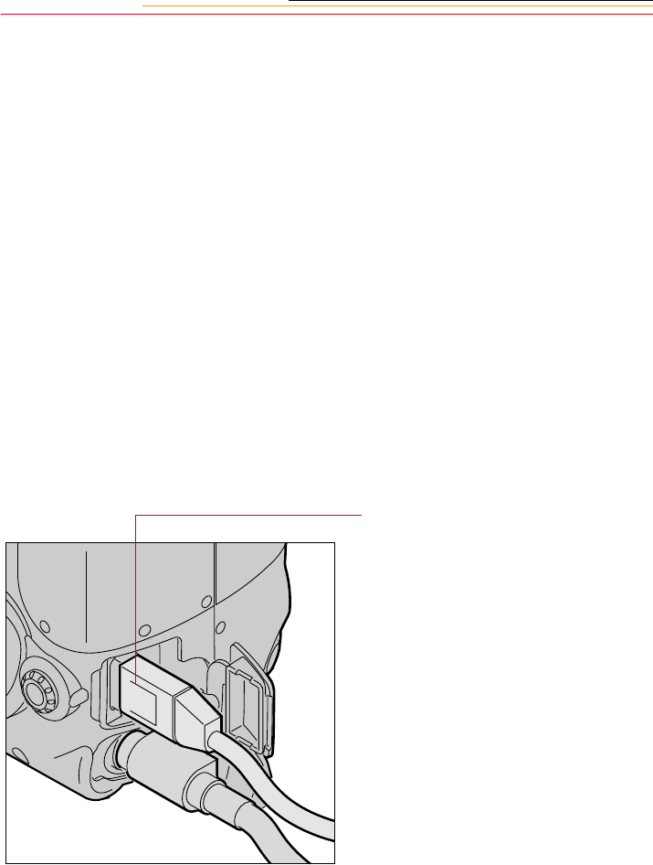
14-2
Connecting Your Camera to the Computer
You connect your camera to the computer using an IEEE 1394 cable. This cable moves
images from the camera to the computer at a very rapid rate. The IEEE 1394 cable is easy
to use—you can plug either end into the camera or the computer, and you don’t need to
turn off the computer or the camera before connecting or disconnecting.
☛You must use an IEEE 1394 connector and adapter card.
To Connect to the Computer
1Charge and insert the battery or hook up the AC adapter. Refer to the “Charging
Batteries” section on page 3-8 or the “Connecting the AC Adapter for Camera”
section on page 3-14.
☛Although it is not necessary to use the AC adapter, it is highly recommended as
insurance against possible loss of data if the battery should lose its charge.
2Install the DCS Host Software for Macintosh or Windows if you have not already done
so. Refer to the KODAK PROFESSIONAL DCS Host Software User’s Manual on the
DCS Host Software CD included with your camera.
3Connect either end of the IEEE
1394 cable into the camera port.
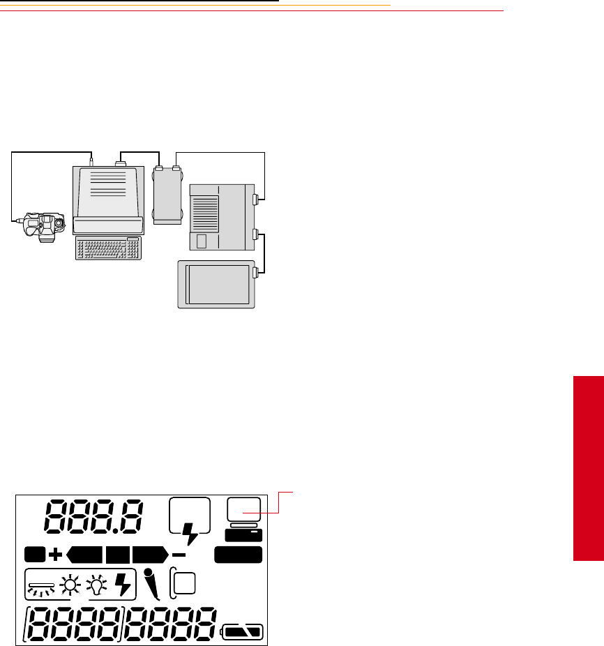
14-3
14
Connecting
4Connect the other end of the
cable into any available port on
the IEEE 1394 adapter card on
your computer.
The adapter card may have
multiple ports.
☛You may connect more than
one camera or other IEEE
1394 devices to the card as
long as you avoid a closed
loop configuration. (The
drawing indicates an
acceptable configuration.)
☛The camera’s IEEE 1394 port
does not support a second
pass-through connector, and is
meant to be the last device on
the “daisy chain.”
You are now ready to access
your camera from the computer.
Refer to the KODAK
PROFESSIONAL DCS Host
Software User’s Manual on the
DCS Host Software CD
included with your camera.
When the camera and computer
are communicating, the
Personal Computer Connection
icon in the Back Status LCD
panel blinks.
REAR
SLOW
AUTO
ISO
BKT CUSTOM
14-4
Quitting—Disconnecting from the Computer
Complete these steps when your work with the camera and the computer is complete.
You can connect or disconnect the camera without turning the camera or the computer Off.
1If the DCS Host Software is running, click the Done button in the Image window.
2Disconnect the camera from the computer.
Using the Card Reader
If your computer has a card reader, you can access images by placing a PC Card
containing camera images in the reader. If you have a new card reader, install it using the
instructions accompanying the reader.
1Remove the PC Card from your camera.
2Insert the PC Card into the card reader on your computer.
☛If your PC is running Windows NT 4.0, you may need to restart the PC each time
you insert a PC Card into the reader.
CAUTION:
Do not disconnect the camera from the computer while the DCS Host Software
Image window is open. Doing so may result in the loss of data from the PC Card.
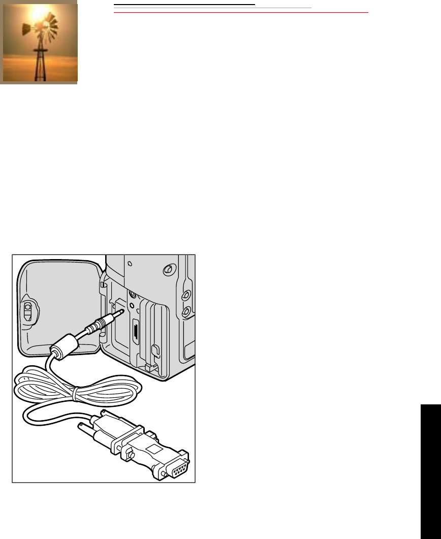
15-1
15
Transmitting
Transmitting Data
15
You can use the serial port on your camera to transfer data between your camera and other
devices. In addition, there is a purchasable option that enables you to transmit images to a
remote location using a cellular phone.
Connecting a Device to the Serial Port
You can connect a variety of devices to your camera’s serial port using a serial cable
(available from your dealer of KODAK products). Devices used to transmit text strings
must be RS-232 compliant.
1Connect the appropriate end of
the serial cable to the serial port
on your camera.
2Connect the other end of the
cable to the device.
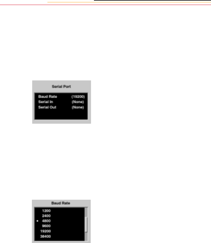
15-2
Accessing Serial Port Options
Setting the Baud Rate
Before transmitting data between the camera and a connected device, you must set the
correct baud rate required by the device. Choose from 300, 600, 1200, 2400, 4800, 9600,
19200, 38400, 57600, and 115200.
1Select the Menu icon, then
choose Main Menu from the
dropdown menu (page 2-14).
2Select Serial Port from the Main
menu.
The Serial Port menu appears.
3Select one of the following:
✔Baud Rate (page 15-2)
✔Serial In (page 15-3)
✔Serial Out (page 15-3)
1Select Baud Rate from the Serial
Port menu (page 15-2).
The Baud Rate menu appears.
2Select the appropriate baud rate
for the connected device.
The setting is retained until you
change it, or modem is selected
as the Serial In or Serial Out
mode. When Modem is selected,
baud rate is automatically set to
19200.
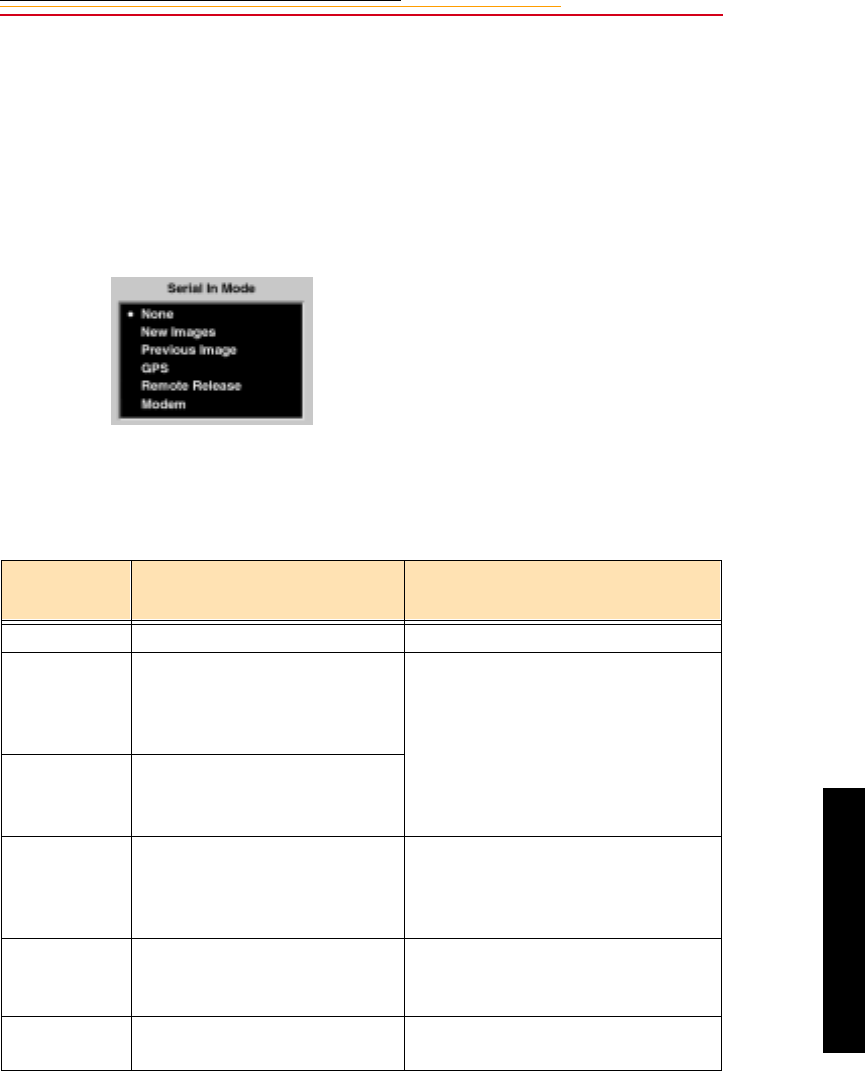
15-3
15
Tramsmitting
Serial In Mode
Using Serial In mode, your camera accepts text strings from a connected external device.
The information is then added to specified image headers.
☛Serial In and Serial Out modes can work at the same time.
1Select Serial In from the Serial
Port menu (page 15-2).
The Serial In Mode menu
appears.
2Select your choice (described in
the table below).
The setting is retained until you
change it, disconnect the device,
or use the Transmit option (page
15-6). Modem is selected
automatically with this option.
Menu
Choice Action Comments
None No data transmitted Serial port is unavailable.
New Images The text string from the
connected device is written to
the header of subsequent
images.
Text string must be 250 valid
characters, or less. Valid characters
consist of ASCII characters, carriage
return, and line termination.
When you select New Images or
Previous Image, a Serial In Status
option (page 15-4) becomes available.
Previous
Image
A text string from the connected
device is written to the header of
previously captured image.
GPS A text string from the connected
GPS device is written to the
header of the just-captured
image.
If a Trimble GPS card is inserted in
the camera, the serial port GPS
functionality is over-ridden by the
Trimble card.
Remote
Release
An image is captured when you
activate the connected remote
cable release.
Use the remote release to minimize
camera movement or when you are
away from the camera.
Modem Reserved for Transmit option
(page 15-6) Set automatically when you use the
Transmit option.
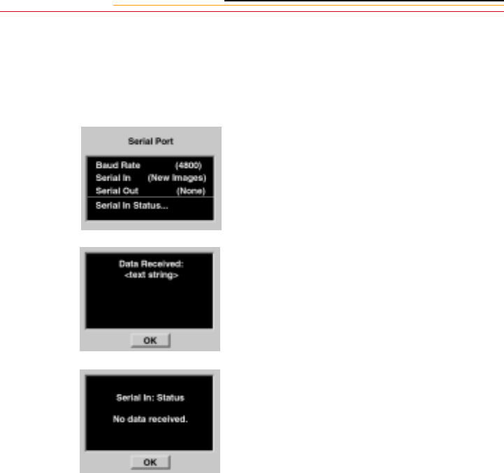
15-4
Serial In Status
When you select New Images or Previous Image from the Serial In Mode menu, the Serial
In Status choice becomes available.
Select Serial in Status from the
Serial Port menu.
If the connected device is sending
data, a message indicates the most
recent data received.
If there is no device connected or if
a connected device is not currently
sending data, this message appears.
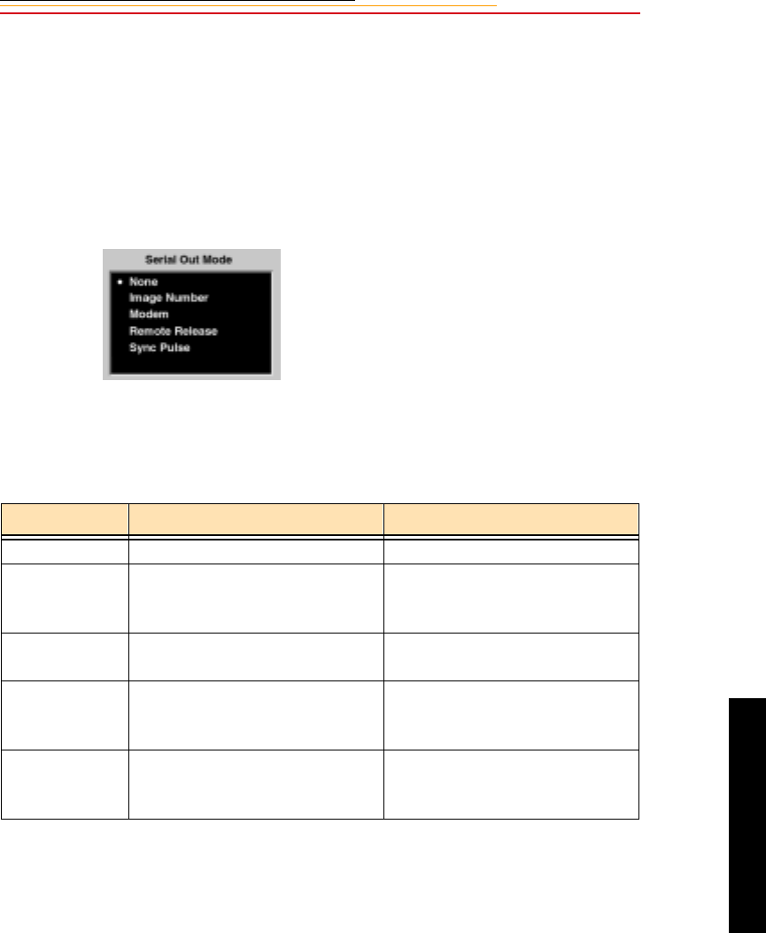
15-5
15
Tramsmitting
Serial Out Mode
When the serial port is in Serial Out mode, your camera sends data to a remotely
connected device.
☛Serial In and Serial Out modes can work at the same time.
1Select Serial Out from the Serial
Port menu (page 15-2).
The Serial Out Mode menu
appears.
2Select your choice (described in
the table below).
The setting is retained until you
change it, or use the Transmit
option (page 15-6). Modem is
selected automatically with this
option.
Menu Choice Action Comments
None No data transmitted
Image Number A text string containing the image
number of the just-captured image
is sent to the connected device.
Modem Reserved for Transmit option
(page 15-6)
Remote Release Remote Release is automatically
selected when you select Remote
Release in the Serial In menu.
Sync Pulse A +3Vdc signal with a duration
identical to the exposure duration
is sent to the connected device.

15-6
Image Transmit
You can transmit images from your camera to a remote computer using a cell phone. The
DCS Transmission kit (available from your dealer of Kodak products) includes hardware
and documentation to be used when you connect your camera to a cell phone. It also
contains a certificate with information that you must use to acquire a special firmware key.
When you load firmware version 3.2 or later into your camera, you can activate the
Transmit option by loading the firmware key.

16-1
16
Camera Care
Camera Care
16
Handling
With careful handling, your camera should produce images of the highest quality for years
to come.
✔Be careful not to drop your camera or subject it to shock. (While the camera has
been designed for durability, it is a precision instrument and should be handled
with care.)
✔ Keep the camera out of salt spray and protect it from excessive moisture. If you
use it at the beach, clean it thoroughly afterward with a dry cloth.
✔Do not leave the camera in an excessively hot place.
✔Do not touch the camera’s electronic contacts with your fingers. Touching the
contacts can cause corrosion and affect proper camera operation.
✔After removing a lens from the camera, place it face down on a flat surface to avoid
damaging the electronic contacts on the lens mount.
✔Condensation is a problem when bringing cold equipment into a warm place. If the
autofocus optics cloud over, accuracy may be seriously affected. Before entering a
warm place, put equipment in a plastic bag so that condensation forms on the
outside of the bag.
✔A spray gun-type blower may damage the optical glass if used to clean the lens,
especially if ED glass is used for the front lens element. To avoid damage, hold the
blower upright with its nozzle more than 30 cm (approximately 12 inches) from the
lens surface, and keep the nozzle moving so that the stream of air is not
concentrated in one spot.
16-2
Cleaning
1Turn off the camera.
2Disconnect the camera from the AC adapter and from the computer if they are
connected.
3Using a damp cloth, clean only the outside cabinet, the Top Status LCD panel, the
Back Status LCD panel, and the Image LCD panel.
☛ Do not use liquid cleaners or aerosol cleaners on the outside of the camera.
4Clean the viewfinder eyepiece with a soft, clean cloth. Do not use alcohol.
5To remove dust from the mirror, or focusing screen, gently blow the dust away using a
commercially-available bulb-type blower. Avoid directly touching any of these
surfaces. Do not wipe the camera body with any type of cleaner containing organic
solvents. When further cleaning is necessary, consult your nearest service center.
6Clean the lens surface with a blower brush. To remove dirt and smudges, remove the
lens from the camera, then use a soft, clean cotton cloth or lens tissue moistened with
ethanol (alcohol) or lens cleaner. Wipe in a circular motion from center to outer edge,
taking care not to leave traces and not to touch the other lens parts.
☛Do not lubricate the camera.
CAUTION:
Remove the lens from the camera before cleaning with alcohol so that no
alcohol gets on the viewfinder eyepiece.
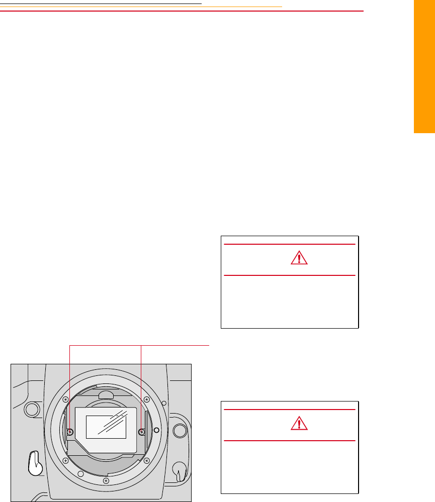
16-3
16
Camera Care
Anti-aliasing Filter and IR Filter
Your camera contains an anti-aliasing or IR filter. It may be necessary to remove the filter
for cleaning. Although it is not essential, you can wear lint-free, static-free gloves,
available from your camera dealer.
☛The anti-aliasing or IR filter can accommodate a fair amount of dust before cleaning
is necessary. It should be cleaned less often than the imager to avoid damage.
Removing, Cleaning, and Re-installing the Anti-aliasing or IR Filter
1Turn off the camera.
2Remove the lens from the
camera.
3Carefully unscrew the two
screws at the sides of the filter
bracket using a jewelers
screwdriver (Phillips #00).
CAUTION:
Be very careful when
removing the filter, as it is a
fragile device.
CAUTION:
Be careful that the screws do
not fall into the camera as they
can cause damage.
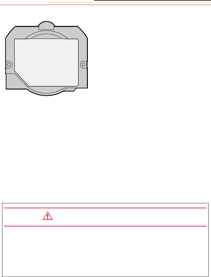
16-4
4Carefully remove the filter
bracket from the camera.
5Gently blow off the dust using
commercially available canned
air. If the anti-aliasing filter is
still dirty, contact your dealer or
service representative.
6To re-install, place the filter
bracket tabs into the upper two
notches on the camera lens
opening, and secure the screws
at the sides.
7Carefully screw in the two
screws. Alternate the tightening
sequence so that each screw is
tightened a little at a time until
both screws are snug. Do not
overtighten or cross-thread the
screen.
8Replace the camera lens. Refer
to “Mounting the Lens” on page
2-21.
CAUTION:
If you break the glass on the anti-aliasing or IR filter while it is in the camera, call
your service representative. The broken glass can damage the imager and other
parts of the camera.
Use only lenses listed in Appendix C. Other lenses can potentially break your
camera’s anti-aliasing filter.

16-5
16
Camera Care
The Imager
The imager records light when you capture an image. If it should get dirty, the quality of
your images can be affected.
Determining if the Imager is Dirty
Even though the imager is located inside the camera, it can get dirty. There are two ways
to determine whether it needs cleaning:
✔Capture a test image and look for imperfections that indicate dirt on the imager.
✔Access, then visually inspect the imager for dirt.
Examining a Test Image
1Connect your camera to your computer. Refer to “Connecting Your Camera to the
Computer” on page 14-2.
2Set the lens aperture to its highest f-stop to provide for maximum depth of field. Refer
to “Aperture-Priority Auto Exposure Mode” on page 13-4 and “Manual Exposure
Mode” on page 13-8.
3Capture an image of a plain white object, such as a clean white wall.
4Examine the image on the computer monitor. Imperfections in the image, such as dark
clusters or streaks, may indicate a dirty imager.
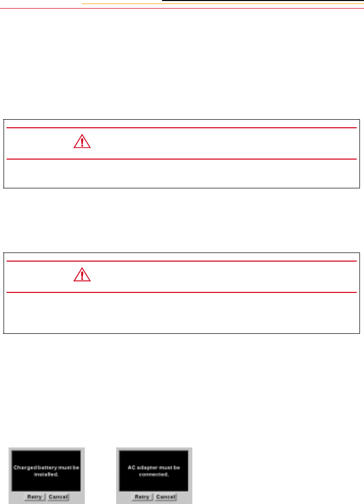
16-6
Visually inspecting the Imager
1Turn off the camera.
2Remove the lens from the camera.
3Remove the anti-aliasing or IR filter.
4Insert a battery, if one is not present.
5Connect the camera to an AC adapter, if one is not already connected.
6Turn on the camera.
7Select the Menu icon, then choose Main Menu from the dropdown menu (page 2-14).
The Main menu appears.
8Select Imager Clean.
CAUTION:
Be very careful when removing the filter, as it is a fragile device.
CAUTION:
Two sources of power are needed as a safeguard to prevent the shutter closing
unexpectedly and being ruined.
If there is no battery in the
camera or the camera is not
connected to the AC adapter, a
screen informs you. Insert a
battery or connect the AC
adapter. Press and hold the
Selector button and use the
Navigate switch to select Retry.
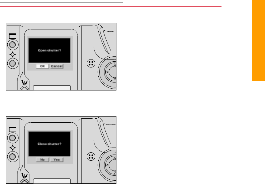
16-7
16
Camera Care
If the battery and AC adapter
are in place, the Open Shutter
screen appears in the Image
LCD panel.
9Select OK to proceed, or Cancel
to cancel the process.
If you chose Cancel, you can
turn off the camera and replace
the filter and lens.
If you chose OK, the mirror
raises and the shutter opens.
The Close Shutter screen
appears in the Image Display.
10 Hold the camera so that light
reflects off the imager. Visually
inspect the imager.
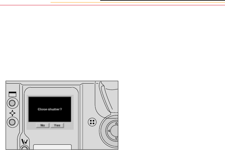
16-8
Cleaning the Imager
If the imager is dirty, check the Kodak Web site for instructions on cleaning.
Reassembling the Camera
You must reassemble your camera after inspecting or cleaning the imager.
1Select Yes in the Close Shutter
screen.
The mirrors lower and the
shutter closes.
2Turn off the camera.
3Carefully replace the anti-
aliasing or IR filter.
4Replace the lens.

16-9
16
Camera Care
Storing
✔When storing your camera, wrap it in a clean, soft cloth and place it in a well-
ventilated, cool, dry, dust-free place.
✔Keep the camera out of direct sunlight, and away from hot spots such as the trunk
or rear window shelf of a car.
✔Avoid places where chemical agents such as moth balls are used.
✔To prevent corrosion, avoid storing the camera in a laboratory or other location
where chemicals are used.
✔Do not store the camera in a drawer or other non-ventilated place.
✔Remove the battery if you do not expect to use the camera for several days.
✔Take the camera out and release the shutter occasionally to prevent build up of
mold or corrosion.
In a humid environment, store the camera inside a vinyl bag with a desiccant to keep out
dust, moisture and salt. Note, however, that storing leather cases in vinyl bags may cause
the leather to deteriorate.
Carefully check the camera’s operation after lengthy storage, when the camera has not
been used for a long time, or before an important trip or shooting assignment.
Top and Back Status LCD panels
Liquid crystal may respond relatively slowly in temperatures below 32 degrees F
(0 degrees C). It may also darken in temperatures of around 140 degrees F (60 degrees C).
The LCD panels return to normal function when the temperature returns to normal.
IMPORTANT:
A minute amount of battery power is used even when the Power switch is set to Off.
This will affect the camera’s shooting capacity after several days of storage.

16-10
Installing Camera Firmware on Your Computer
Firmware is the software program that runs within the camera and controls its operation.
Access new firmware versions them from the Kodak WWW site (http://www.kodak.com).
Before you update the firmware on your camera, install it on your computer.
Download the firmware from the Kodak WWW site. From the Kodak Home page, search
for Digital Cameras, DCS 600 Series, and look for software download instructions.
Updating Camera Firmware
Once you download the firmware to your computer, you can update the firmware on your
camera.
There are two ways to update your camera’s firmware:
✔Using the DCS Host software while your camera is connected to the computer
using IEEE 1394 cable.
✔Update from the PC Card
Refer to the KODAK PROFESSIONAL DCS Host Software User’s manual (on the DCS
Host Software CD included with your camera) for instructions on updating using the DCS
Host software.
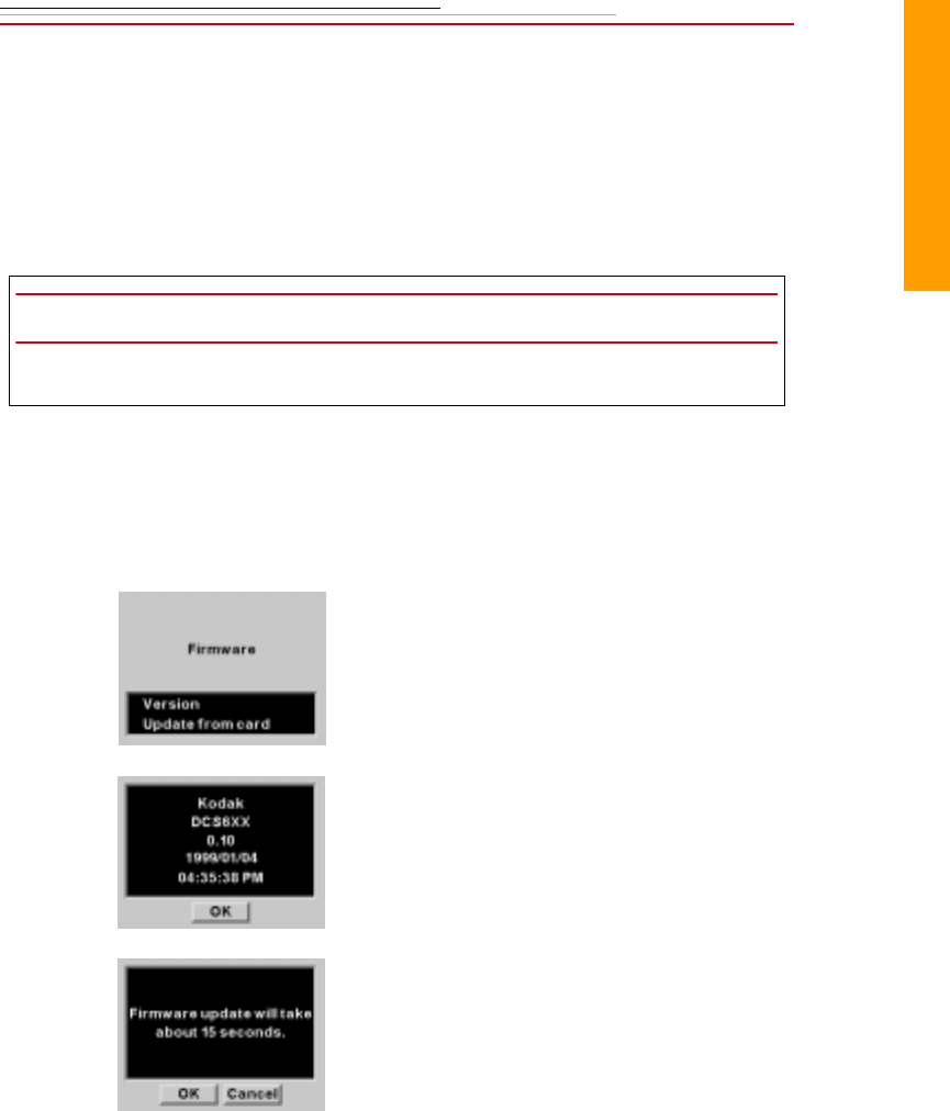
16-11
16
Camera Care
Updating From the PC Card
1Install the firmware on your computer.
2Insert a PC Card into the card reader on your computer. Refer to “Using the Card
Reader” on page 14-4.
3On your computer, copy the firmware file (dcs6xx.bin) to the cards root directory.
4Insert the card in your camera. Refer to “Inserting/Removing PC Cards” on page 5-3.
5Select the Menu icon, then choose Main Menu from the dropdown menu (page 2-14).
6Select Firmware from the Main menu.
IMPORTANT:
Place the firmware file in the root directory. It will not work if placed in a folder.
7The Firmware screen appears.
8Select Version or Update from
card.
If you choose Version, the
version number of the camera
firmware appears.
If you choose Update from card,
a second screen appears.
9Choose OK or Cancel.
If you choose Cancel, the
firmware will not be updated.
The process takes approximately
15 seconds.

Appendix A
A-1
Appendix A - Specifications
Type of camera Integral-motor autofocus 35 mm single-lens reflex
Imager size DCS 620 and 620x: 2 million pixels
DCS 660 and 660M: 6 million pixels
Lens mount Nikon F mount
Lens Refer to Appendix C
Focus mode Autofocus and Manual with Electronic Rangefinder
AF area mode Single Area AF and Dynamic AF selectable
Autofocus area Five selectable focus areas
Autofocus mode Single Servo AF with Focus-Priority and Continuous Servo AF with
Release-Priority
Focus Tracking Automatically activated when subject moves
Autofocus detection system Nikon Multi-CAM1300 autofocus module
Autofocus detection range Approximately EV –1 to EV +19 at ISO 200
Autofocus lock Possible once stationary subject is in focus in Single Servo AF; in
Continuous Servo AF, focus can be locked with AE-L/AF-L button
Electronic rangefinder Available in Manual focus mode with AF Nikkor and other AI-type
Nikkor lenses with a maximum aperture of f/5.6 or faster
Exposure metering Three built-in exposure meters ––3D Color Matrix, Center-Weighted,
and Spot
Metering range at ISO 200 with f1.4
lens)
EV0 to EV20 in 3D Color Matrix and Center-Weighted, EV2 to EV
20 in Spot
Exposure meter ON/OFF Activated when the Shutter Release button or AF start button is
pressed or when other camera controls are operated; turns off after 8
seconds or when the camera is switched Off
Exposure mode Programmed Auto, Shutter-Priority Auto, Aperture-Priority Auto, and
Manual
Programmed auto exposure control Camera sets both shutter speed and lens aperture automatically;
Flexible Program is possible in increments of 1/3 EV
Shutter-priority auto exposure
control
Aperture automatically selected to match manually set shutter speed
Aperture-priority auto exposure
control
Shutter speed automatically selected to match manually set aperture
Manual exposure control Both aperture and shutter speed are set manually
Exposure compensation With exposure compensation button; ±5 EV range, in 1/3 EV steps
Auto exposure lock By pressing the AE-L/AF-L button while meter is on

A-2
Shutter speeds Lithium niobate oscillator-controlled speeds from 1/8000 to 30
seconds (in 1/3 stop increments); electromagnetically controlled Bulb
setting
Viewfinder Nikon multi-meter finder DP-30 provided as standard for the DCS
660 and 660M, modified for the DCS 620 and 620x; fixed eyelevel
pentaprism high-eyepoint type; 0.8X magnification with 50mm lens
set at infinity; approximately 100% frame coverage; metering system
selector, diopter adjustment knob, accessory shoe and eyepiece shutter
lever provided; interchangeable with Nikon AE action finder DA-30,
6X high-magnification finder DW-31 and waist-level finder DW-30
with limited functionality
Eyepoint Approximately 20.5 mm
Eyepiece shutter Provided
Focusing screen Nikon advanced EC-B-type screen; interchangeable with 12 other
optional screens
Viewfinder information LCD shows metering system, focus indication, exposure mode,
shutter speed, aperture, electronic analog exposure display, exposure
compensation value and exposure compensation mark; exposure level
indicators, flash ready-light LED, aperture direct-readout, focus
indicators and focus area indicators are also shown
Top LCD panel information Shutter speed, aperture, exposure information mode, AF area mode,
focus area, Flexible Program mark, exposure compensation mark,
exposure compensation value, exposure bracketing mark, and shutter
speed/aperture/ focus area position lock marks
Back LCD panel information ISO, Flash Sync mode, personal computer connection, auto exposure/
flash exposure bracketing, custom setting, white balance, microphone
active, card present, frame number, frames remaining, battery level
LCD panel illumination LCD panel illuminated by rotating power/LCD panel illumination
switch
ISO range DCS 620: 200 - 1600 in 1/3 stop increments
DCS 620x: 400 - 4000 in 1/3 stop increments
DCS 660: 80 - 200 in 1/3 stop increments
DCS 660M: 320 - 800 in 1/3 stop increments
Frame counter Counts the number of images captured
Frame rate
Refer to “Continuous Shooting” on page 10-12.
Self-timer Electronically controlled; 10 seconds duration (can be changed to
interval from 2 to 60 seconds using custom setting #16.)
Depth-of-field Preview button Provides visual verification of depth of field
Shooting Mode DCS 620,
620x DCS 660,
660M
CH (Continuous High) 3.5 fps 1.0 fps
CL (Continuous Low) 2.0 fps .15 fps
CS (Continuous Silent) 1.0 fps .15 fps

A-3
Appendix A
Reflex mirror Automatic, instant-return type
Accessory shoe Standard ISO-type hot-shoe contact; ready-light contact, monitor
contact; mount receptacle for SB-28D/SB-28/SB-27/SB-26/SB-25’s
Posi-Mount System provided
Flash sync control Slow Sync and Rear-Curtain Sync built-in
Flash synchronization In Programmed Auto or Aperture-Priority Auto, shutter operates from
1/250 to 1/60 second in normal sync, 1/250 to 30 seconds in slow
sync; in Shutter-Priority Auto or Manual exposure mode, shutter
operates at speed set, or at 1/250 if speed is set between 1/250 and
1/8000 seconds 1/300 TTL High-Speed Sync can be selected using
Custom Setting #20 in Shutter-Priority Auto or Manual exposure
mode.
Flash ready-light Speedlight attached: Lights up in red when Nikon dedicated
Speedlight is ready to fire, or blinks to warn of insufficient light for
correct exposure
Power source Single, rechargeable nickel cadmium or NIMH battery
Battery power confirmation On Back Status LCD panel
External Battery Charger Charges one or two batteries
AC Adapter An alternative power source that allows you to conserve your battery
while working indoors.
Dimensions Width: 158 mm, Height: 194 mm, Depth: 88 mm
Weight 1.86 KG. This is the weight of a camera containing a battery and PC
Card with no lens attached.

Appendix B
B-1
Appendix B - Troubleshooting
If you run into a problem operating your camera, check the following table to see if you
can find the cause of the problem. If the trouble persists, take the camera to your nearest
dealer or service center.
Top Status
LCD Panel Viewfinder Shutter Cause and Remedy
No indication No indication Locked The battery is exhausted or improperly
installed. Rotate the power switch to OFF and
replace the battery.
FEE blinks FEE blinks Can be released In Programmed Auto or Shutter-Priority Auto
exposure mode, the lens is not set to the
smallest aperture setting. Set the lens to the
smallest aperture.
F-- appears F-- appears Can be released With built-in CPU lens in Aperture-Priority
Auto or Manual exposure mode, lens is not set
to the smallest aperture setting. Set the lens to
the smallest aperture with the Sub-Command
Dial. Aperture can also be set by rotating the
lens aperture ring. In this case, F-- remains in
the viewfinder and top LCD panel, and aperture
can only be confirmed through the aperture
direct-readout in the viewfinder.
Non-CPU lens is attached. Programmed Auto
or Shutter-Priority Auto exposure mode cannot
be selected. Set aperture by rotating lens
aperture ring. In this case, aperture can only be
confirmed through the aperture direct-readout
in viewfinder.
Err and Alert LED
blink
Err and Alert LED
blink
Locked Your camera has detected an abnormality in the
shutter diaphragm. Turn it off and on. If the
same warnings continue to blink, take the
camera to an authorized dealer or service
center.
— appears when
3D Color Matrix
Metering is selected.
Can be released 3D Color Matrix Metering is set even though
attached lens has no CPU; camera
automatically resets meter to Center-Weighted
Metering.
(•)

B-2
P or S blinks A appears Can be released Programmed Auto or Shutter-Priority Auto
exposure mode is set even though attached lens
has no CPU. Camera automatically resets
exposure mode to Aperture-Priority Auto.
— blinks Locked Autofocus (and manual focus with Electronic
Rangefinder) is not possible. Focus manually.
H| appears H| appears Can be released Overexposure possible
Lo appears Lo appears Can be released Underexposure possible
Selected shutter
speed blinks
25o or Custom set
sync speed appears
Can be released In Shutter-Priority Auto or Manual exposure
mode, selected shutter speed is faster than
1/250 or selected flash sync speed in Custom
Setting.
appears blinks Can be released Auto Exposure/Flash Exposure Bracketing is
selected.
Top Status
LCD Panel Viewfinder Shutter Cause and Remedy
BKT +/-

B-3
Appendix B
Other symptoms, causes and remedies:
Symptom Cause Remedy
The camera settings cannot be
changed.
The camera is turned Off Turn on the camera.
Autofocusing does not operate. The Focus Mode selector is set to
M.
Set the Focus Mode selector to C
or S.
The shutter does not release. The camera is busy writing to the
PC Card.
Wait until the PC Card icon on the
Back Status LCD panel stops
blinking.
The subject is not in focus. Wait until the subject is in focus.
No room on PC Card Replace the PC Card or delete
some images.
No PC Card in camera Insert a PC Card
The Frames Remaining indicator
on the Back Status LCD panel
reads 0.
The PC Card is full Insert a different PC Card or delete
some images from the PC Card.
The battery icon on the Back
Status LCD panel shows that the
battery is low.
Battery is low Recharge the battery, replace it
with a freshly charged battery, or
connect the AC adapter.
Exposed a burst of images and the
Card icon continues to flash.
It takes time to save a burst of
images.
Wait a few seconds.
The camera is “locked.” Nothing
works.
The battery is not securely in place. Remove then insert the battery.
The camera turned Off. This can be caused by static
electricity or a poorly loaded
battery.
Turn the camera off then on, or
remove the battery and install it
again.
You just inserted a new battery and
the camera is “locked.”
You didn’t turn the camera Off
before changing batteries.
Turn off the camera. Remove the
new battery. Wait 10 seconds,
insert the same battery, then turn
the camera On.
The Depth-of-Field Preview button
does not work properly.
No PC Card is inserted. Insert a PC Card.

Appendix C
C-1
Appendix C - Lens and
Viewfinder Compatibility
Compatible Lenses
Your camera works with the following NIKKOR lenses. Some work with the camera’s
antialiasing or IR filter in place, some work without it, and some work in either situation.
(Use the table below as a reference.)
You cannot use non-AI or modified AI lenses with your camera.
Manual Single Focal Length Lenses
Lens Name Lens Type Works with
Antialiasing or IR
Filter
Works without
Antialiasing or IR
Filter
Ai 6/2.8S Fish Eye x x
Ai 8/2.8 Fish Eye x
Ai 8/2.8S Fish Eye x x
Ai 13/5.6 x x
Ai 13/5.6S x x
Ai 15/5.6 x x
Ai 15/3.5 x x
Ai 15/3.5S x x
Ai 16/2.8 Fish Eye x x
Ai 16/2.8S Fish Eye x x
Ai 16/3.5 Fish Eye x x
Ai 18/3.5S x
Ai 18/4 x
Ai 20/2.8S x
Ai 20/3.5 x

C-2
Ai 20/3.5S x
Ai 20/4 x
Ai 24/2 x x
Ai 24/2S x
Ai 24/2.8 x x
Ai 24/2.8S x
Ai 28/2 x x
Ai 28/2S x
Ai 28/2.8 x x
E 28/2.8 x
Ai 28/2.8S x x
Ai 28/3.5 x x
Ai 28/3.5S x x
Ai 35/1.4 x x
Ai 35/1.4S x x
Ai 35/2 x x
Ai 35/2S x x
E 35/2.5 Series E x
Ai 35/2.8 x x
Ai 35/2.8S x x
Ai 50/1.2 x x
Ai 50/1.2S x x
Ai 50/1.4 x x
Ai 50/1.4S x x
Ai 50/1.8 x x
Ai 50/1.8S x
E 50/1.8 x
Ai 50/2 x x
Ai 55/1.2 x x
Ai 55/2.8 Micro x x
Ai 55/2.8S Micro x x
Lens Name Lens Type Works with
Antialiasing or IR
Filter
Works without
Antialiasing or IR
Filter

C-3
Appendix C
Ai 55/3.5 Micro x
Ai 58/1.2 Noct x
Ai 58/1.2S Noct x x
Ai 85/1.4S x x
Ai 85/2 x x
Ai 85/2S x x
E 100/2.8 x x
Ai 105/1.8S x x
Ai 105/2.5 x x
Ai 105/2.5S x x
Ai 105/2.8S Micro x x
Ai 105/4 Micro x x
Ai 105/4S Micro x x
Ai 105/4.5S Ultra Violet x x
Ai 135/2 x x
Ai 135/2S x x
Ai 135/2.8 x x
Ai 135/2.8S x x
E 135/2.8 x x
Ai 135/3.5 x x
Ai 135/3.5S x x
Ai 180/2.8 x x
Ai 180/2.8S x x
Ai 200/2 x x
Ai 200/2S x x
Ai 200/4 x x
Ai 200/4S x x
Ai 200/4 Micro x x
Ai 200/4S Micro x x
Ai 300/2S x x
Ai 300/2.8 x x
Lens Name Lens Type Works with
Antialiasing or IR
Filter
Works without
Antialiasing or IR
Filter

C-4
1 Lenses with product number 906200 and before cannot be used.
2 Lenses with product number between142361 and 143000 cannot be used.
3 Lenses with product number between 200111 and 200310 cannot be used.
Ai 300/2.8S x x
Ai 300/4.5 x x
Ai 300/4.5S x x
Ai 300/4.5 x x
Ai 300/4.5 x x
Ai 300/4.5S x x
Ai 400/2.8S x x
Ai 400/3.5 x x
Ai 400/3.5S x x
Ai 400/5.6 x x
Ai 400/5.6 x x
Ai 400/5.6S x x
Ai 500/4S x x
Ai 600/4 x x
Ai 600/4S x x
Ai 600/5.6 x x
Ai 600/5.6S x x
Ai 800/5.6S x x
Ai 800/8 x x
Ai 800/8S x x
Ai 1200/11 x x
Ai 1200/11S x x
28/3.5 Perspective Control x x
35/2.8 Perspective Control x1x1
500/8 Reflex x x
1000/11 Reflex x2x2
2000/11 Reflex x3x3
120/4 Micro x x
Lens Name Lens Type Works with
Antialiasing or IR
Filter
Works without
Antialiasing or IR
Filter

C-5
Appendix C
Manual Zoom Lenses
Lens Name Lens Type Works with
Antialiasing
Filter
Works without
Antialiasing
Filter
Ai Zoom25-50/4 x x
Ai Zoom25-50/4S x x
Ai Zoom28-45/4.5 x x
Ai Zoom28-50/3.5S x x
Ai Zoom28-85/3.5-
4.5S
xx
Ai Zoom35-70/3.3-
4.5S
xx
Ai Zoom35-70/3.5 x x
Ai Zoom35-70/3.5S x x
Ai Zoom35-105/3.5-
4.5S xx
Ai Zoom35-135/3.5-
4.5S xx
Ai Zoom35-200/3.5-
4.5S xx
E Zoom36-72/3.5 Series E x x
Ai Zoom43-86/3.5 x x
Ai Zoom50-135/
3.5S
xx
Ai Zoom50-300/4.5 x x
Ai Zoom50-300/4.5 x x
Ai Zoom50-300/
4.5S
xx
E Zoom70-210/4 Series E x x
E Zoom75-150/3.5 Series E x x
Ai Zoom80-200/
2.8S xx
Ai Zoom80-200/4S x x
Ai Zoom80-200/4.5 x x

C-6
Autofocus Single Focal Length Lenses
Ai Zoom100-300/
5.6S xx
Ai Zoom180-600/8S x x
Ai Zoom200-400/4S x x
Ai Zoom200-600/
9.5S
xx
Ai Zoom360-1200/
11S
xx
Ai Zoom1200-1700/
5.6-8S
xx
Lens Name Lens Type Works with
Antialiasing
Filter
Works without
Antialiasing
Filter
AF 16/2.8D Fish Eye x x
AF 18/2.8D x x
AF 20/2.8 x x
AF 20/2.8D x x
AF 24/2.8 x x
AF 24/2.8D x x
AF 28/1.4D x x
AF 28/2.8 x x
AF 28/2.8D x x
AF 35/2 x x
AF 35/2D x x
AF 50/1.4 x x
AF 50/1.4D x x
AF 50/1.8 x x
AF 55/2.8 Micro x x
AF 60/2.8 Micro x x
Lens Name Lens Type Works with
Antialiasing
Filter
Works without
Antialiasing
Filter

C-7
Appendix C
Autofocus Zoom Lenses
AF 60/2.8D Micro x x
AF 85/1.8 x x
AF 85/1.8D x x
AF 85/1.4D x x
AF 105/2D Defocus Control x x
AF 105/2.8 Micro x x
AF 105/2.8D Micro x x
AF 135/2 Defocus Control x x
AF 135/2D Defocus Control x x
AF 180/2.8 x x
AF 180/2.8D x x
AF 200/4D Micro x x
AF 300/2.8 x x
AF 300/4 x x
AF I 300/2.8D x x
AF I 400/2.8D x x
AF I 500/4D x x
AF I 600/4D x x
AF S 300/2.8D x x
AF S 400/2.8D x x
AF S 500/4D x x
AF S 600/4D x x
Lens Name Lens Type Works with
Antialiasing
Filter
Works without
Antialiasing
Filter
AF Zoom 20- 35/
2.8D xx
AF Zoom 24- 50/
3.3-4.5 xx
Lens Name Lens Type Works with
Antialiasing
Filter
Works without
Antialiasing
Filter

C-8
AF Zoom 24- 50/
3.3-4.5D xx
AF Zoom 24- 120/
3.5-5.6D xx
AF Zoom 28 - 70/
3.5-4.5 xx
AF Zoom 28 - 70/
3.5-4.5D xx
AF Zoom 28- 80/
3.5-5.6D xx
AF Zoom 28- 85/
3.5-4.5S xx
AF Zoom 28- 85/
3.5-4.5 xx
AF Zoom 28-200/
3.5-5.6D xx
AF Zoom 35- 70/2.8 x x
AF Zoom 35- 70/
2.8D
xx
AF Zoom 35- 70/
3.3-4.5
xx
AF Zoom 35- 80/
4.0-5.6D
xx
AF Zoom 35-105/
3.5-4.5
xx
AF Zoom 35-105/
3.5-4.5D
xx
AF Zoom 35-135/
3.5-4.5
xx
AF Zoom 70-210/4 x x
AF Zoom 70-210/4-
5.6
xx
AF Zoom 70-210/4-
5.6D
xx
Lens Name Lens Type Works with
Antialiasing
Filter
Works without
Antialiasing
Filter

C-9
Appendix C
Compatible Viewfinders
AF Zoom 70-300/
4.5-5.6D xx
AF Zoom 70-300/
4.5-5.6 xx
AF Zoom 80-200/
2.8
xx
AF Zoom 80-200/
2.8D xx
AF Zoom 80-200/
4.5-5.6D xx
AF Zoom 75-180/
4.5-5.6D Micro x x
IX Zoom 20-60/3.5-
5.6
IX Zoom 24-70/3.5-
5.6
IX Zoom 60-180/
3.5-5.6
Viewfinder Number
Multi-meter finder DCS 620, 620x: Modified
DP-30
DCS 660, 660M: Standard
DP-30
Action finder DA-30
Waist-level finder DW-30
High-magnification finder DW-31
Lens Name Lens Type Works with
Antialiasing
Filter
Works without
Antialiasing
Filter

Appendix D
D-1
Appendix D - Glossary
AE (Automatic Exposure) lock
Used to hold an automatically controlled shutter speed and/or aperture.
Recommended when the photographer wants to control an exposure based on a
scene’s particular brightness area with Center-Weighted or Spot Metering.
Antialiasing filter
Helps to reduce aliasing at certain focal distances
CCD (Charge coupled device)
The part of the camera that captures images
Continuous Servo AF
Focus detection continues as long as shutter release button is lightly pressed and
the reflex mirror is in the viewing position. Useful when the camera-to-subject
distance is likely to change.
CPU
Central Processing Unit. The electronic component that controls an electronic
product’s functions.
AF Nikkor (including D-type AF Nikkor) and AI-P-Nikkor lenses have built-in
CPUs.
Depth of field
The zone of sharpest focus in front of, behind, and around the subject; can be
previewed in the F5 and some other Nikon cameras.
Drive mode
Drive mode determines whether one or more images are captured when you are
pressing the Shutter Release button. There are four automatic Drive modes: Single
frame, Continuous low-speed shooting, Continuous high-speed shooting, and
Continuous silent-low-speed shooting.

D-2
EV
Exposure Value: A number representing the available combinations of shutter
speeds and apertures that give the same exposure effect under conditions of similar
scene brightness and ISO.
At ISO 100, the combination of a one-second shutter speed and an aperture of f/1.4
is defined as EV1.
The camera may be used only within the EV range of the exposure meter. For
example, with the F5, the exposure metering range is from EV0 to EV20 for 3D
Color Matrix Metering and Center-Weighted Metering, at ISO 100 with an f/1.4
lens.
Exposure bracketing
Shooting the same subject using a range of different exposures. Your camera
provides Auto Exposure Bracketing/Flash Exposure Bracketing.
Auto Exposure Bracketing: Auto Exposure Bracketing performs automatic
exposure bracketing with varied shutter speed and/or aperture.
Flash Exposure Bracketing: Enables you to automatically bracket exposures at
varied flash output levels, in TTL auto flash shooting, without changing the shutter
speed and/or aperture.
Exposure compensation
Exposure compensation for available light is activated by changing the shutter
speed and/or lens aperture. This is done by using AE-L/AF-L (Auto Exposure/
Autofocus Lock) button or exposure compensation button, or by Auto Exposure
Bracketing.
In flash photography with a Nikon-dedicated TTL Speedlight, exposure
compensation can also be performed by varying the amount of flash output.
Camera-originated exposure compensation affects both the foreground subject and
the background; variations in flash output amount affect only the foreground.
Exposure control
Programmed Auto: Camera sets both shutter speed and aperture for correct
exposure.
Shutter-Priority Auto: User selects shutter speed and camera sets matching lens
aperture for correct exposure.
Aperture-Priority Auto: User selects aperture and camera sets matching shutter
speed for correct exposure.
Manual: User selects both shutter speed and aperture, following or ignoring the
meter’s recommendations to achieve the desired exposure.

D-3
Appendix D
F-number
The numbers on the lens aperture ring and in the camera’s LCD that indicate the
relative size of the lens aperture opening. The f-number series is a geometric
progression based on changes in the size of the lens aperture, as it is opened and
closed. As the scale rises, each number is multiplied by a factor of 1.4. The
standard numbers for calibration are 1.0, 1.4, 2, 2.8, 4, 5.6, 8, 11, 16, 22, 32, etc.,
and each change results in a doubling or halving of the amount of light transmitted
by the lens.
Flexible Program
Flexible Program function temporarily shifts an automatically selected shutter
speed/aperture combination while maintaining correct exposure. That is, a desired
shutter speed or aperture can be selected in Programmed Auto exposure mode.
Focus-Priority for autofocus
The shutter cannot be released until the subject is in focus.
Focus-Priority is given to Single Servo AF mode while Release-Priority is given to
Continuous Servo AF.
Focus Tracking
Enables the camera to analyze the speed of the moving subject according to the
focus data detected, and to obtain correct focus by anticipating the subject’s
position—and driving the lens to that position—at the exact moment of exposure.
Focal length
The distance from the principal point to the focal point. In 35 mm-format cameras,
lenses with a focal length of approximately 50 mm are called normal or standard
lenses. Lenses with a focal length less than approximately 35 mm are called wide
angle lenses, and lenses with a focal length more than approximately. 85 mm are
called telephoto lenses. Lenses which allow the user to continuously vary the focal
length without changing focus are called zoom lenses.
Front-Curtain Sync
The flash fires an instant after the front curtain of a focal plane shutter has
completed its travel across the film plane. This is the way the F5 operates with the
flash sync mode at Normal Sync. See also “Rear-Curtain Sync.”

D-4
Guide number
The guide number indicates the power of a flash in relation to ISO. Guide numbers,
quoted in either meters or feet, are used to calculate the f/stop for correct exposure
as follows:
guide number
f/stop = ———————————
flash-to-subject distance
Using a selected aperture, we can calculate the required flash-to-subject distance
with the formula:
guide number
flash-to-subject distance = ———————
f/stop
Useful for determining the maximum flash-to-subject distance for flash
photography.
Histogram
The image histogram shows the range and distribution of tonal values for an image.
The histogram displays the number of occurrences of each pixel code value, and
can be used to assess an image's brightness and contrast levels. Pixel code values
represent the relative value of light intensities in a scene. They range from 0
(darkest elements in a scene) to 255 (brightest elements in a scene). For a high
contrast image, the histogram will include almost the entire range of pixel code
values. For a low contrast image, the histogram will include a small range of pixel
code values.
ISO
ISO is the international standard for representing film sensitivity. The higher the
number, the greater the sensitivity, and vice versa. For example, ISO 200 is twice
as sensitive as ISO 100, and half that of ISO 400. When you change the ISO setting
on your camera, you adjust the sensitivity of the imager equivalent to the
corresponding film sensitivity.
LCD
Liquid Crystal Display. Your camera has four: the Top Status LCD panel, Back
Status LCD panel, Image LCD panel, and the LCD inside the viewfinder.

D-5
Appendix D
Manual flash
Flash output is controlled manually in manual flash mode, unlike in auto flash
mode, where flash output power varies automatically according to the selected
aperture. Some Speedlights, including the Nikon SB-28, SB-27, SB-26, SB-25,
SB-24 and SB-20, provide selectable manual outputs (full, 1/2, 1/4, 1/8, 1/16, etc.),
while others provide full manual output only.
Matrix Metering system
An advanced exposure metering system using a multi-segment sensor and
computer.
3D Color Matrix Metering: With Multi-Meter Finder DP-30 and D-type AF
Nikkor lenses, 3D Color Matrix Metering is automatically activated with the F5.
With the classic techniques of evaluating for 18% reflectance, factors such as
brightness and contrast are primarily used to determine exposure. In addition, it is
essential to evaluate each scene’s esthetic factors such as color to get the best
exposure. The shadows of a building, cool with blue. A panoramic landscape with
a bright blue sky. Or a winter scene covered with pristine white snow. Your
camera’s 3D Color Matrix Meter evaluates not only each scene’s brightness and
contrast but, using a special Red-Green-Blue (RGB) sensor, it also evaluates the
scene’s colors. Then its powerful microcomputer and database together guide it to
unequaled exposure control.
PC Card (PCMCIA card)
The media which stores images captured by your camera. Your camera is designed
to accept Type I, Type II, or Type III PC Cards which are compatible with the
PCMCIA-ATA interface standard. Most hard disk drive and flash memory cards
may be used. Hard disk drive cards will hold more images and are usually faster
than flash memory cards, but flash memory cards are more rugged.
Rear-Curtain Sync
Flash fires an instant before the second (rear) curtain of the focal plane shutter
begins to move. When slow shutter speeds are used, this feature can create a blur
effect from the ambient light, i.e., a flowing-light patterns following a moving
subject with subject movement frozen at the end of the light flow. See also Front-
Curtain Sync.

D-6
Release-Priority for autofocus
Shutter can be released anytime (i.e., even when subject is not in focus). Helps you
avoid missed opportunities when you are not concerned with absolute focusing
precision.
Release-Priority is given to Continuous Servo AF mode while Focus-Priority is
given to Single Servo AF. Using Custom Setting, however, you can change the
priority to Focus-Priority Continuous Servo AF or Release-Priority Single Servo
AF.
Single Servo AF
Once the subject is in focus, focus is locked. Useful for recomposing the picture.
Slow Sync
A flash technique for using the flash at a slow shutter speed. Flash shooting in dim
light or at night at a fast shutter speed often results in a flash-illuminated subject
against a dark background. Using a slower shutter speed with the flash brings out
the background details in the picture. Use of a slow shutter speed with Rear-
Curtain Sync is particularly effective for illustrating the movement of a stream of
light.
Slow Sync mode extends the automatically controlled shutter speed range (in
Programmed Auto and Aperture-Priority Auto) down to 30 seconds.
SLR
Single Lens Reflex. A type of camera that allows you to see through the camera
lens as you look in the viewfinder. Other camera functions, such as light metering
and flash control, also operate through the camera’s lens.
Vignetting
Progressively diminished illumination on the image from the center to the corners.
There are two kinds of vignetting—natural vignetting caused by the lens, and
vignetting that is caused by improper use of accessories such as a lens hood or
filter.
White balance
Provides adjustments to match the type of lighting used to capture an image.

Appendix E
E-1
Appendix E - Problem Report
KODAK PROFESSIONAL DCS 600 Series Digital Cameras
Customer Return Address
Name______________________________________________________________
Company___________________________________________________________
Address____________________________________________________________
___________________________________________________________________
___________________________________________________________________
City________________________________State_____Zip_____________--______
Phone ( ) ______________________________________________________
Equipment Description
Camera Serial Number -- K____________________________________________
(See the bottom of the camera next to “S/N.” The serial number begins with a “K.”)
Problem Description
___________________________________________________________________
___________________________________________________________________
___________________________________________________________________
___________________________________________________________________
___________________________________________________________________
___________________________________________________________________
___________________________________________________________________

Appendix F
F-1
Appendix F - Remote Control
Accessories
The following accessories (available from Nikon) are compatible with your camera:
Nikon
Code Name Compatibility Notes Adapter
MC-20 Remote card Yes
MC-21 Extension cord Yes
MC-22 Remote cord with
banana terminal
Yes
MC-23 Connecting cord for
simultaneous shutter
release
No Necessary signal not
provided from 10 pin
terminal
MC-30 Remote cord Yes
MC-33 Personal computer
connecting cord
(Windows)
No Necessary signal not
provided from 10 pin
terminal
MC-34 Personal computer
connecting cord
(Macintosh)
No Necessary signal not
provided from 10 pin
terminal
MT-1 Intervalometer No Switch 1 does not
provide proper signal
MT-2 Intervalometer Yes Pulse duration should
be set to over 0.2 sec. MC-25
MW-1 Radio control unit No Switch 1 does not
provide proper signal
MW-2 Radio control unit Yes AF-switch should be set
to AF-On MC-25
ML-1 Modulite remote
control set No Switch 1 does not
provide proper signal

F-2
ML-2 Modulite remote
control set
Yes MC-25
ML-3 Modulite remote
control set
Yes
AC-1WE Computer link
software package
(for Windows)
Out of use Necessary signal does
not provide from 10 pin
terminal
AC-1ME Computer link
software package
(for Macintosh)
Out of use Necessary signal does
not provide from 10 pin
terminal
MF-27 Data back Out of use Can not attach
MF-28 Multi-control back Out of use Can not attach
Nikon
Code Name Compatibility Notes Adapter

Index-1
Index
Numerics
3D Color Matrix Metering 8-10
A
AC Adapter 3-13, 7-5
Connecting 3-14, 7-5
Accessory Shoe 2-30
Actuations 4-6
AE/AF Lock 13-16
AF Area Mode
Selecting 9-4
Anti-aliasing Filter 2-25, 16-3
Cleaning 16-3
Effect on Focus 9-15
Re-installing 16-3
Removing 16-3
Aperture
Locking 13-7
Setting 13-4, 13-9
Aperture-Priority Auto Exposure Mode
Capturing Images In 13-4
Auto Aperture Mode 11-2
Auto Exposure/Flash Exposure Bracketing
13-24
Autofocus 9-6
Continuous Servo AF with Release-
Priority 9-9
Single Servo AF with Focus-Priority
9-7
B
Back Status LCD Panel 2-12
Basic Shooting 7-8, 10-3
Batteries 3-2
Charging 3-8, 7-1
Checking Status of 3-6
Conditioning 3-10
Conserving 3-11
Discharging 3-10
Inserting 3-3, 7-2
Removing 3-3
Battery Charger 3-7
Battery/PC Card Door 2-7
Baud Rate 15-2
C
Camera
Back 2-4
Battery/PC Card Door 2-7
Bottom 2-5
Care 15-1, 16-1
Front 2-3
Handling 15-1, 16-1
Properties
See Properties
Sides 2-6
Specifications A-1
Storage 16-9
Top 2-5
Turning on and off 3-1
Capturing Images 10-1
Basic Shooting 7-8, 10-3
Preparations 10-1
Card Reader 14-1, 14-4
Using 14-4
Cards
Inserting 7-2
Center-Weighted Metering 8-11
Charging Batteries 3-8, 7-1
Cleaning
Antialiasing Filter 16-3
Imager 16-8
Your Camera 16-2
Clock 4-1
Computer
Connecting to 14-2
Disconnecting From 14-4
System Requirements 1-2
Conditioning Batteries 3-10
Configuring Your Camera 4-1
Connecting to the Computer 14-2

Index-2
Conserving Batteries 3-11
Continuous Servo AF with Release-
Priority 9-9
Continuous Shooting 10-12
Custom Settings 13-32
Description 13-34
Making 13-32
Resetting to Factory Settings 13-33
Using the Properties Menu 4-7
D
Data 6-8
Date and Time 4-1, 7-7
DCS 600 Series
Camera Back 2-4
Camera Bottom 2-5
Camera Front 2-3
Camera Sides 2-6
Camera Top 2-5
Specifications A-1
Deleting Images
All in Folder or PC Card 12-14
Multiple Images 7-19, 12-14
Single Image 7-18, 12-13
Untagged Images in Folder or PC Card
12-14
Depth-of-Field Preview Button 2-29
Dioptric Adjustment of the Viewfinder 4-3
Discharging Batteries
See Conditioning Batteries
Disconnecting From Your Computer 14-4
Display Button 2-10
Display Contrast 7-14
Adjusting 7-14, 12-6
Display Off Time 4-3
Display Options 12-8
Highlight 12-8
Histogram 7-15, 12-9
Setting 12-8
Drive Mode 10-10
Choosing 10-10
Continuous Shooting 10-12
Single Frame Shooting 10-11
Drive Mode/Self-Timer Selector 2-20
E
Electromagnetic Emissions 1-7
Exposure Compensation 13-19
Modifying 13-22
Exposure Metering
3DColor Matrix Metering 8-10
Center-Weighted Metering 8-11
Setting 8-13
Spot Metering 8-12
Exposure Mode
Aperture-Priority Auto Exposure
Mode 8-15
Capturing Images In 13-4
Manual Exposure Mode 8-16
Capturing Images In 13-8
Obtaining Meter Reading 13-20
Programmed Auto Exposure Mode 8-
14
Setting 8-17
Shutter-Priority Auto Exposure Mode
8-15
Capturing Images In 13-1
F
Features 2-1
Firmware
Installing on Your Computer 16-10
Updating 16-10
From PC Card 16-11
Flash
Auto Aperture Mode 11-2
Flash Photography 11-1
Aperture Controlled Auto Flash 11-1
SB-28D 11-1
Setting Up the SB-28D 11-7
Setting Up Your Camera For 11-5
Test Firing 11-9

Index-3
Index
Flash Sync Mode 11-13
Rear Curtain Sync 11-15
Slow Sync 11-13
Flexible Program 13-13
Focus Area
Locking 9-3
Selecting 9-1
Focus Lock for Off-center Subjects 13-14
Focus Mode
Autofocus 9-6
Continuous Servo AF with
Release-Priority 9-9
Single Servo AF with Focus-
Priority 9-6
Manual Focus 9-10
Using a Clear Matte Field 9-13
With Electronic Rangefinder 9-11
Single Servo AF with Focus-Priority
Moving Subject 9-8
Single Subject 9-7
Focusing
Special Situations 9-13
Tips 9-13
Focusing Screen
Changing 2-34
Folders
Selecting 7-7
Use Folder 1 4-6
Formatting a PC Card 5-6
Four Image Review Mode 12-3
G
Glossary D-1
H
Handling your Camera 16-1
Highlighting 7-15
Histogram 7-16
I
IEEE 1394 Connection 14-1
Illumination Switch 2-27
Image
Selecting 12-7
Image LCD Panel 2-12
Timeout 3-12
Image Review Mode 7-13, 12-1
Four Image Review Mode 12-3
Navigating 12-3
Nine Image Review Mode 12-3
Setting 12-2
Single Image Review Mode 12-3
Imager 16-5
Cleaning 16-8
Determining if Dirty 16-5
Overview 2-25
Images
Capturing 10-1
Installing Camera Firmware 16-10
Intervalometer 10-14
IPTC 6-8
IR Filter 2-25, 16-3
ISO 10-9
J
JPEG Files 6-1
L
LCD Panels
Back LCD Panel 16-9
Back Status LCD Panel 2-12
Effects of Temperature on 16-9
Top LCD Panel 2-6, 16-9
Top Status LCD Panel 2-11
Lens 2-21
Autofocus Single Lenses C-6
Autofocus Zoom Lenses C-7
Compatibility C-1
Manual Single Lenses C-1
Manual Zoom Lenses C-5
Mounting 2-21

Index-4
Removing 2-24
Locking Shutter Speed 13-3
Locking Shutter Speed/Aperture 13-11
Long Time Exposure 13-30
M
Macintosh
System Requirements 1-2
Main-Command Dial 2-17
Manual Exposure Mode 8-16
Capturing Images In 13-8
Obtaining Meter Reading 13-19, 13-
20
Manual Focus 9-10
Using a Clear Matte Field 9-13
Using the Electric Rangefinder 9-11
Mirror Lockup Lever 2-28
N
Navigate Switch
General Usage 2-9
Navigating
Horizontally Through Images 12-4
Vertically Through Images 12-5
Neck Strap 2-35
Nine Image Review Mode 12-3
Nomenclature 2-3
P
PC Card Reader 14-1
PC Cards 5-1
Formatting 5-6
Inserting 5-3
Removing 5-3
Types 5-1
PCMCIA Card
See PC Cards 5-1
Power Cords 3-8, 7-6
PowerSave Mode 3-11
Setting Time 4-3
Precautions 1-4
Problem Report E-1
Processing
Changing Settings 6-5
Images 6-2
With 2 PC Cards 6-1
Programmed Auto Exposure Mode 8-14
Properties 4-3
Display Time 4-3
PowerSave Time 4-3
Total Actuations 4-6
Use Folder 1 4-6
R
Rear Curtain Sync 11-15
Reassembling Camera 16-8
Recharging Batteries
See Conditioning Batteries
Record/Tag Button 2-10
Recording Sound Files 7-20, 12-11
Recovering Deleted Images 12-15
Resetting Factory Settings 13-33
Resolution 4-5
Review Mode
See Image Review Mode
Reviewing Images 7-13, 12-3
Navigating Horizontally 12-4
Navigating Vertically 12-5
Setting the Review Mode 7-13, 12-2
S
Safeguards 1-4
SB-28D
Attaching 11-3
Setting Up 11-7
Standby Mode 11-4
Test Firing 11-9
Turning On 11-3
Using 11-10

Index-5
Index
Selecting Images 7-13, 12-7
Selector Button 2-10
Self Timer 13-28
Self-Diagnostic Shutter System 2-31
Serial In
Mode 15-3
Status 15-4
Serial Out Mode 15-5
Serial Port Options 15-2
Serial Port, Connecting 15-1
Sharpening 4-4
Shutter Speed
Locking 13-3
Shutter Speed/Aperture
Locking 13-11
Shutter-Priority Auto Exposure Mode 8-15
Capturing Images In 13-1
Single Frame Shooting 10-11
Single Image Review Mode 12-3
Single Servo AF with Focus-Priority 9-6
Moving Subject 9-8
Single Subject 9-7
Slow Sync 11-13
Sound Files
Recording 7-20, 12-11
Specifications A-1
Spot Metering 8-12
Standby Mode 11-4
Storing Your Camera 16-9
Sub-Command Dial 2-19
Sync Terminal 2-30
System Requirements
Macintosh 1-2
Windows 1-2
T
Tagging Images 7-17, 12-10
Test Firing 11-9
TIFF Files 6-1
Time. See Date and Time
Top Status LCD Panel 2-11
Total Actuations 4-6
Troubleshooting B-1
Turning the camera on or off 3-1
Two-Button Reset 10-8
U
Universal Power Cords 3-8, 3-14, 7-6
V
VCCI Statement 1-7
Vertical Controls 10-13
Viewfinder 2-8
Changing 2-33
Compatibility C-1
Viewfinder Diopter 2-26
W
Warnings 1-3
White Balance 8-1
Button 2-10
Color Temperature 8-2
Determining Current Settings 8-2
White Balance Settings 8-4
Deleting 8-6
Loading 8-7
Saving 8-9
Selecting 8-6
Windows
System Requirements 1-2
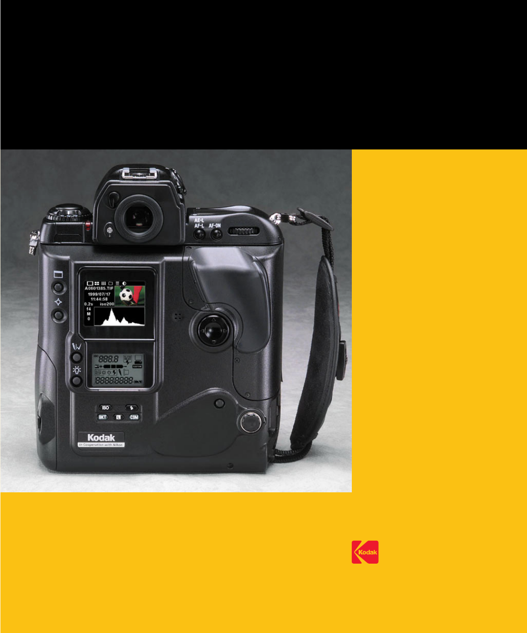
EASTMAN KODAK COMPANY
Kodak Professional Division
Rochester, New York 14650
www.kodak.com/go/professional
© Eastman Kodak Company, 2000.
Kodak and Kodak Professional are
trademarks.
P/N 4E1627
