Kodak I600 Series Users Manual A 61500, User's Guide For Scanners
2015-02-04
: Kodak Kodak-I600-Series-Users-Manual-370936 kodak-i600-series-users-manual-370936 kodak pdf
Open the PDF directly: View PDF ![]() .
.
Page Count: 70
- Contents
- 1 Introduction
- 2 Getting Started
- 3 Using the Scanner
- Turning the scanner on and off
- Starting and stopping scanning
- Manually pausing and resuming the scanner
- Automatically pausing and resuming the scanner
- Manually ending scanning
- Document preparation
- Adjusting the side guides and end stop
- Locking the side guides
- Adjusting the back of the output tray
- Adjusting the front of the output tray
- Adjusting the output tray for long documents up to 43 cm (17 in.)
- Adjusting the output tray for documents from 43 cm (17 in.) to 86 cm (34 in.)
- Exit deflector
- Adjusting the optional short document tray
- Feeding documents using multi-feed detection
- Automatic feeding
- Continuous feeding
- Manual feeding
- Feeding documents that require special handling
- Calibrating the scanner
- 4 The Enhanced Printer
- 5 Maintenance
- 6 Troubleshooting
- Appendix A Accessories
- Appendix B Specifications


A-61500 April 2007 i
Contents
1 Introduction . . . . . . . . . . . . . . . . . . . . . . . . . . . . . . . . . . . . . . . . . . . . . . . . 1-1
Scanner models . . . . . . . . . . . . . . . . . . . . . . . . . . . . . . . . . . . . . . . . . . . . 1-2
Optional accessories . . . . . . . . . . . . . . . . . . . . . . . . . . . . . . . . . . . . . . . . . 1-2
Scanner features . . . . . . . . . . . . . . . . . . . . . . . . . . . . . . . . . . . . . . . . . . . . 1-2
Speed/capacity (throughput) . . . . . . . . . . . . . . . . . . . . . . . . . . . . . . . . . . . 1-3
Supporting documentation . . . . . . . . . . . . . . . . . . . . . . . . . . . . . . . . . . . . . 1-3
Safety information . . . . . . . . . . . . . . . . . . . . . . . . . . . . . . . . . . . . . . . . . . . 1-4
MSDS . . . . . . . . . . . . . . . . . . . . . . . . . . . . . . . . . . . . . . . . . . . . . . . . 1-4
User precautions . . . . . . . . . . . . . . . . . . . . . . . . . . . . . . . . . . . . . . . . 1-4
Gas springs warning . . . . . . . . . . . . . . . . . . . . . . . . . . . . . . . . . . . . . 1-4
Environmental information . . . . . . . . . . . . . . . . . . . . . . . . . . . . . . . . . . . . . 1-4
EMC statements . . . . . . . . . . . . . . . . . . . . . . . . . . . . . . . . . . . . . . . . . . . . 1-5
United States . . . . . . . . . . . . . . . . . . . . . . . . . . . . . . . . . . . . . . . . . . . 1-5
Japan . . . . . . . . . . . . . . . . . . . . . . . . . . . . . . . . . . . . . . . . . . . . . . . . . 1-5
Taiwan . . . . . . . . . . . . . . . . . . . . . . . . . . . . . . . . . . . . . . . . . . . . . . . . 1-5
Peoples Republic of China . . . . . . . . . . . . . . . . . . . . . . . . . . . . . . . . . 1-5
Acoustic emission . . . . . . . . . . . . . . . . . . . . . . . . . . . . . . . . . . . . . . . . . . . 1-5
Power system connection . . . . . . . . . . . . . . . . . . . . . . . . . . . . . . . . . . . . . 1-5
2 Getting Started . . . . . . . . . . . . . . . . . . . . . . . . . . . . . . . . . . . . . . . . . . . . . . 2-1
Site specifications . . . . . . . . . . . . . . . . . . . . . . . . . . . . . . . . . . . . . . . . . . . 2-1
System requirements . . . . . . . . . . . . . . . . . . . . . . . . . . . . . . . . . . . . . . . . . 2-1
Registering your scanner . . . . . . . . . . . . . . . . . . . . . . . . . . . . . . . . . . . . . 2-1
Making connections . . . . . . . . . . . . . . . . . . . . . . . . . . . . . . . . . . . . . . . . . . 2-2
Installing the IEEE-1394 card in the host computer . . . . . . . . . . . . . . 2-2
Installing the Kodak Driver software . . . . . . . . . . . . . . . . . . . . . . . . . 2-2
Installing the FireWire cable . . . . . . . . . . . . . . . . . . . . . . . . . . . . . . . 2-2
Attaching the power cord . . . . . . . . . . . . . . . . . . . . . . . . . . . . . . . . . . 2-3
Powering up the host computer . . . . . . . . . . . . . . . . . . . . . . . . . . . . . 2-3
Scanner components . . . . . . . . . . . . . . . . . . . . . . . . . . . . . . . . . . . . . . . . . 2-3
3 Using the Scanner . . . . . . . . . . . . . . . . . . . . . . . . . . . . . . . . . . . . . . . . . . . 3-1
Turning the scanner on and off . . . . . . . . . . . . . . . . . . . . . . . . . . . . . . . . . 3-1
Starting and stopping scanning . . . . . . . . . . . . . . . . . . . . . . . . . . . . . . . . . 3-1
Manually pausing and resuming the scanner . . . . . . . . . . . . . . . . . . . . . . 3-2
Automatically pausing and resuming the scanner . . . . . . . . . . . . . . . . . . . 3-2
Manually ending scanning . . . . . . . . . . . . . . . . . . . . . . . . . . . . . . . . . . . . . 3-2
Document preparation . . . . . . . . . . . . . . . . . . . . . . . . . . . . . . . . . . . . . . . 3-3
Adjusting the side guides and end stop . . . . . . . . . . . . . . . . . . . . . . . . . . . 3-4
Locking the side guides . . . . . . . . . . . . . . . . . . . . . . . . . . . . . . . . . . . . . . . 3-5
Adjusting the back of the output tray . . . . . . . . . . . . . . . . . . . . . . . . . . . . . 3-5
Adjusting the front of the output tray . . . . . . . . . . . . . . . . . . . . . . . . . . . . . 3-6
Adjusting the output tray for long documents up to 43 cm (17 in.) . . . . . . 3-6
Adjusting the output tray for documents from 43 cm (17 in.) to
86 cm (34 in.) . . . . . . . . . . . . . . . . . . . . . . . . . . . . . . . . . . . . . . . . . . . . . . 3-7
Exit deflector . . . . . . . . . . . . . . . . . . . . . . . . . . . . . . . . . . . . . . . . . . . . . . . 3-7
Adjusting the optional short document tray . . . . . . . . . . . . . . . . . . . . . . . . 3-8
Feeding documents using multi-feed detection . . . . . . . . . . . . . . . . . . . . . 3-9
Automatic feeding . . . . . . . . . . . . . . . . . . . . . . . . . . . . . . . . . . . . . . . . . . . 3-9
Continuous feeding . . . . . . . . . . . . . . . . . . . . . . . . . . . . . . . . . . . . . . . . . . 3-9
Manual feeding . . . . . . . . . . . . . . . . . . . . . . . . . . . . . . . . . . . . . . . . . . . . 3-10
Feeding documents that require special handling . . . . . . . . . . . . . . . . . . 3-10

ii A-61500 April 2007
Calibrating the scanner . . . . . . . . . . . . . . . . . . . . . . . . . . . . . . . . . . . . . . 3-11
Image calibration . . . . . . . . . . . . . . . . . . . . . . . . . . . . . . . . . . . . . . . 3-11
Ultrasonics calibration . . . . . . . . . . . . . . . . . . . . . . . . . . . . . . . . . . . 3-14
4 The Enhanced Printer . . . . . . . . . . . . . . . . . . . . . . . . . . . . . . . . . . . . . . . . 4-1
Overview . . . . . . . . . . . . . . . . . . . . . . . . . . . . . . . . . . . . . . . . . . . . . . . . . . 4-1
Printer specifications . . . . . . . . . . . . . . . . . . . . . . . . . . . . . . . . . . . . . . . . . 4-2
Changing print positions . . . . . . . . . . . . . . . . . . . . . . . . . . . . . . . . . . . . . . 4-3
Changing the front horizontal print positions . . . . . . . . . . . . . . . . . . . 4-3
Installing an ink cartridge . . . . . . . . . . . . . . . . . . . . . . . . . . . . . . . . . . . . . . 4-5
Replacing the blotter strips . . . . . . . . . . . . . . . . . . . . . . . . . . . . . . . . . . . 4-7
5 Maintenance . . . . . . . . . . . . . . . . . . . . . . . . . . . . . . . . . . . . . . . . . . . . . . . . 5-1
Cleaning frequency chart . . . . . . . . . . . . . . . . . . . . . . . . . . . . . . . . . . . . . . 5-2
Cleaning tools and materials . . . . . . . . . . . . . . . . . . . . . . . . . . . . . . . . . . . 5-2
Supplies and accessories . . . . . . . . . . . . . . . . . . . . . . . . . . . . . . . . . . . . . 5-3
Ordering parts. . . . . . . . . . . . . . . . . . . . . . . . . . . . . . . . . . . . . . . . . . . . . . . 5-3
Cleaning procedures . . . . . . . . . . . . . . . . . . . . . . . . . . . . . . . . . . . . . . . . . 5-4
Replacement procedures . . . . . . . . . . . . . . . . . . . . . . . . . . . . . . . . . . . . 5-12
Replacing the feed module or feed module tires . . . . . . . . . . . . . . . 5-12
Replacing the separation roller or separation roller tires . . . . . . . . . 5-16
Replacing the pre-separation pad . . . . . . . . . . . . . . . . . . . . . . . . . . 5-17
Replacing the imaging guides . . . . . . . . . . . . . . . . . . . . . . . . . . . . . 5-17
6 Troubleshooting . . . . . . . . . . . . . . . . . . . . . . . . . . . . . . . . . . . . . . . . . . . . . 6-1
Indicator lights . . . . . . . . . . . . . . . . . . . . . . . . . . . . . . . . . . . . . . . . . . . . . . 6-1
Accessing the Operator Log . . . . . . . . . . . . . . . . . . . . . . . . . . . . . . . . . . . 6-3
Message listing . . . . . . . . . . . . . . . . . . . . . . . . . . . . . . . . . . . . . . . . . . . . . 6-6
Numerical message listing . . . . . . . . . . . . . . . . . . . . . . . . . . . . . . . . . . . . 6-11
Problem solving . . . . . . . . . . . . . . . . . . . . . . . . . . . . . . . . . . . . . . . . . . . . 6-13
Appendix A Accessories . . . . . . . . . . . . . . . . . . . . . . . . . . . . . . . . . . . . .A-1
Ultra-Lightweight Paper Feed Module . . . . . . . . . . . . . . . . . . . . . . . . . . . .A-1
White Background Accessory . . . . . . . . . . . . . . . . . . . . . . . . . . . . . . . . . .A-1
Appendix B Specifications . . . . . . . . . . . . . . . . . . . . . . . . . . . . . . . . . . . .B-1

A-61500 April 2007 1-1
1 Introduction
This User’s Guide provides information and procedures for the Kodak
i600 Series Scanners. The information in this guide is for use with all of
the i600 Series Scanners unless otherwise noted.
Chapter 1, Introduction — provides general information about the
i600 Series Scanners including a product description, scanner features,
safety information and user precautions.
Chapter 2, Getting Started — includes specifications and instructions
on how to install the Kodak i600 Series Scanner. Also provides an
overview of internal and external scanner components.
Chapter 3, Using the Scanner — includes information on how to
prepare your documents for scanning, document feeder and output tray
adjustments, scanner calibration and how to scan documents.
Chapter 4, Using the Enhanced Printer — provides procedures for
using and maintaining the Enhanced Printer.
Chapter 5, Maintenance — provides maintenance procedures for the
i600 Series Scanners, including replacement procedures for the feed
module, separation roller and imaging guides.
Chapter 6, Troubleshooting — provides a description of the LED
indicators, a problem solving chart, procedures for clearing a document
jam and a listing of error messages.
Appendix A, Accessories — provides a description of the optional
accessories that can be purchased to support the Kodak i600 Series
Scanners. Instructions for using these accessories are included with
the accessory.
Appendix B, Specifications — provides a listing of the specifications
for the Kodak i600 Series Scanners.

1-2 A-61500 April 2007
Scanner models • Kodak i610 Scanner is a desktop duplex black and white and
grayscale scanner with an automatic document feeder that runs at 80
pages per minute which includes an enhanced printer.
•Kodak i620 Scanner is a desktop duplex color scanner with an
automatic document feeder that runs at 80 pages per minute which
includes an enhanced printer.
•Kodak i640 Scanner is a desktop duplex color scanner with an
automatic document feeder that runs at 100 pages per minute which
includes an enhanced printer.
•Kodak i660 Scanner is a desktop duplex color scanner with an
automatic document feeder that runs at 120 pages per minute which
includes an enhanced printer.
Optional accessories Kodak Feeder Kit for Ultra-Lightweight Paper — allows you to feed
lightweight paper from a paper weight range of 25 to 75 g/m2
(7 to 20 lbs).
Kodak White Background Accessory — if you are scanning
translucent documents, this accessory will reduce black background
bleed-through which produces whiter images.
See Appendix A, Accessories for more information.
Scanner features • Excellent paper handling, image quality, and reliability.
• Color or grayscale at the same speed as black and white.*
• Includes the Brightness and Contrast Control which allows you to
create custom color tables.*
• Simultaneous black and white and color image output.*
• Simultaneous black and white and grayscale image output.
• Handles a broad range of paper weights and sizes.
• Easy installation.
• ISIS and TWAIN device drivers are included on a CD that is packed
with each scanner.
• International language support.
• Ergonomic design.
• 500-sheet elevator tray.
• Energy Star compliant (also known as “sleep” mode).
• Document printing capabilities.
• Electronic red, green and blue color dropout.
• Output resolutions include:
- black and white: 200, 240, 300, 400
- Color:* 100, 150, 200, 240, 300
- Grayscale: 100, 150, 200, 240, 300
• Multi-feed detection by multiple ultrasonic sensors as well as by
length detection.
* Not applicable to the Kodak i610 Scanner.

A-61500 April 2007 1-3
• Automatic and manual feeding.
• JPEG compression allows color and grayscale images to be viewed
in most image viewers.
• Image processing features include: iThresholding, Adaptive
Threshold Processing, orthogonal rotation, color, black and white and
grayscale deskew, auto-crop, automatic color detection, aggressive
cropping, error diffusion, toggle patch, auto-color balancing (auto-
white balancing) to ensure good color balance after calibration, and
more.
• Easily replaceable feed module and separation roller.
Speed/capacity
(throughput)
The following speeds (pages per minute) are for color/grayscale and
black and white output.
Supporting
documentation
The following documentation is available to support the Kodak i600
Series Scanners:
•Image Processing Guide, A-61504 — available in PDF format on
the Installation CD.
•Quick Tips Guide, A-61501— intended to be used as a quick
reference for basic scanner use.
•FireWire Installation Information, A-61511 — this installation
information is packed with the FireWire cable and should be used to
make the required FireWire cable connections.
•White Background Accessory Instructions, A-61503 — when you
purchase the White Background Accessory these instructions are
included and provide a description of how to install the accessory.
•Ultra-Lightweight Feeder Accessory Instructions, A-61190 —
when you purchase the Ultra-Lightweight Feeder Accessory these
instructions are included and provide a description of how to use the
Ultra-Lightweight Feed Module.
•Brightness and Contrast Control Reference Guide, A-61506 —
provides information and procedures for using the Brightness and
Contrast Control which allows you to create your own custom color
tables.
Resolution (dpi) Landscape Letter Portrait Letter
Color/Gray Black and
White
i610/i620 i640 i660 i610/i620 i640 i660
100 - 80 100 120 69 83 96
150 - 80 100 120 69 83 96
200 200 80 100 120 69 83 96
240 240 53 66 80 46 55 64
300 300 53 66 80 46 55 64
-400<53 <66 <80 <46 <55 <64

1-4 A-61500 April 2007
Safety information Warning labels
MSDS Material Safety Data Sheets (MSDS) are available on the Kodak
website at: www.kodak.com/go/msds. When accessing the MSDSs
from the website, you will be required to provide the catalog number of
the consumable you want the Material Safety Data Sheet for. See
Chapter 5, “Supplies and accessories” for consumables and catalog
numbers.
User precautions Users and their employer need to observe the common sense
precautions applicable to the operation of any machinery. These
include, but are not limited to, the following:
• Do not wear loose clothing, unbuttoned sleeves, etc.
• Do not wear loose jewelry, bracelets, bulky rings, long necklaces, etc.
• Hair length should be kept short, using a hair net if needed, or tying
long hair up in a bundle.
• Remove all other loose objects from the area that could be drawn into
the machine.
• Take sufficient breaks to maintain mental alertness.
Supervisors should review their practices and make compliance with
these precautions a part of the job description for operation of the
scanner or any mechanical device.
Gas springs warning If the gas springs exhibit a sign of decayed performance, call Service
for replacement. Do not attempt to repair.
Environmental
information
• The Kodak i600 Series Scanners contain lead in the circuit board
solder. Disposal of this material may be regulated due to
environmental considerations. For disposal or recycling information,
please contact your local authorities or, in the USA, visit the
Electronics Industry Alliance website: www.eiae.org.
• The product packaging is recyclable.
• The i600 Series Scanners are Energy Star compliant and are shipped
from the factory with the default time set to 15 minutes.
CAUTION: Moving parts, avoid contact.
CAUTION: Hot surface, avoid contact.
A-61500 April 2007 1-5
EMC statements
United States This equipment has been tested and found to comply with the limits for
a Class A digital device pursuant to Part 15 of the FCC rules. These
limits are designed to provide reasonable protection against harmful
interference when the equipment is operated in a commercial
environment. This equipment generates, uses, and can radiate radio
frequently energy and, if not installed and used in accordance with the
instruction manual, may cause harmful interference to radio
communications. Operation of this equipment in a residential area is
likely to cause harmful interference in which case the user will be
required to correct the interference at his own expense.
Japan This is a Class A product based on the standard of the Voluntary
Control Council for interference by information Technology Equipment
(VCCI). If this equipment is used in a domestic environment, radio
disturbance may arise. When such trouble occurs, the user may be
required to take corrective action.
Taiwan WARNING: This is a Class A product. In a domestic environment this
product may cause radio interference in which case the user may be
required to take adequate measures.
Peoples Republic of
China
WARNING: This is a Class A product. In a domestic environment this
product may cause radio interference in which case the user may be
required to take adequate measures.
Acoustic emission Maschinenlärminformationsverordnung – 3, GSGV
Der arbeitsplatzbezogene Emissionswert beträgt <70 db(A).
[Machine Noise Information Ordinance — 3, GSGV
The operator-position noise emission value is <70 dB(A).]
Power system
connection
This product is also designed for Norwegian IT power system with
phase-to-phase voltage 230V.
声明,该产
此为A级产品,在生活环境中品可能会造成无线电干扰。在这种情况下,可能需要
用户对其干扰采取切实可行的措施

A-61500 April 2007 2-1
2 Getting Started
Site specifications Place the scanner:
• In a clean area with temperature and relative humidity typical of an
office environment,
• on a stable, level work surface,
• within 1.52 metres (5 feet) of an electrical power outlet.
IMPORTANT: Only use the scanner indoors in a dry location.
For more information about the scanner specifications, refer to
Appendix B, Specifications.
System requirements Following is the minimum recommended system configuration to run
Kodak i600 Series Scanners.
NOTE: The actual performance of the system depends on the scanning
application, choice of scanning parameters, and the host
computer configuration. If the scanner is not performing at the
optimal speed, a faster computer and/or more RAM may be
necessary to obtain the rated throughput.
• Intel PC (or compatible) with a Pentium IV 2 GHz processor
•PCI slot
• Microsoft Windows 2000 Professional, Windows XP (Professional/
Home)
• 512 MB RAM
• Monitor
• Mouse
Registering your
scanner
It is very important that you register your scanner so Kodak can provide
you with the best possible service and support that helps maintain your
continuous scanning. Registering your scanner will help us provide you
with firmware and hardware updates as they become available.
The scanner must be registered before any service support can be
provided.
You can register your scanner’s new equipment warranty online at
www.kodak.com/go/DIwarrantyregistration.
For more information about Kodak’s service and support options,
contact your reseller of Kodak Document Imaging products or visit us
on the web at www.kodak.com/go/DIserviceandsupport.
2-2 A-61500 April 2007
Making connections Follow the instructions for installing the IEEE-1394 (FireWire) card and
the Kodak driver software before you plug the scanner into the host
computer.
IMPORTANT:You must install the software on the host computer
before you connect the scanner.
Installing the IEEE-1394
card in the host
computer
Install the IEEE-1394 (FireWire) card according to the directions
supplied with the IEEE-1394 card.
IMPORTANT: Use proper precautions to avoid static when you install
the IEEE-1394 card in your computer. Make sure the
computer power cord is disconnected.
Installing the Kodak
Driver software
1. Insert the Kodak i600 Series Scanners installation CD in the CD-
ROM drive. The installation program starts automatically.
2. Follow the on-screen instructions to install the TWAIN Datasource,
ISIS Driver and the Kodak Scan Validation Tool.
3. Shut down the host computer.
Installing the FireWire
cable
An IEEE-1394 six-pin connector is provided on the rear panel of the
scanner for IEEE-1394 connectivity.
1. Plug the end of the cable with the right angle into the scanner.
2. Connect the other end of the cable into the IEEE-1394 card outlet in
the host computer. Be sure that it is installed correctly and properly
seated.
CAUTION: DO NOT FORCE THE CONNECTOR. If the cable is not
properly connected, it could cause damage to the
scanner.
A-61500 April 2007 2-3
Attaching the power cord The Kodak i600 Series Scanner is packed with a set of power cords.
1. Select the power cord which complies with your electrical
requirements and attach it.
2. Turn on the scanner and wait until the top green LED is lit indicating
the scanner has completed power-up self-test and is idle.
Powering up the host
computer
• Turn the power on to the host computer.
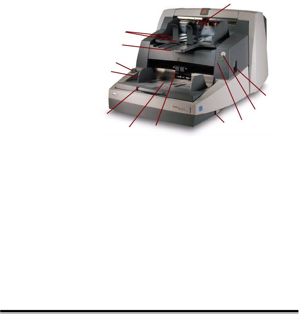
Scanner components Front view
1 Elevator tray extender — open the elevator tray extender to
accommodate long documents.
2 Feed module — provides smooth document feeding of various
sizes, thicknesses and textures.
CAUTION:Moving parts, avoid contact.
3 Elevator tray side guides — slide the guides in or out to
accommodate the document size you want to scan. Side guides
can be left-, center- and right-adjusted to accommodate
documents of various widths. The side guides can also be locked
into position if desired.
4 Gap Release lever — allows you to manually adjust the space
between the feed module and separation roller for documents that
require special handling.
5 Output tray and End stop — collects the scanned documents.
The output tray width and end stop length can be adjusted.
6 POD release latch — push up the POD release latch when you
need to access the inside of the scanner.
1
11 2
3
4
5
10
7
6
8
9
12*

2-4 A-61500 April 2007
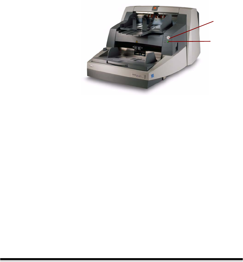
7 Stop/Pause and Start/Resume buttons —
8LEDs— illuminate or flash from top to bottom as follows:
Illuminates when the power is turned on and the scanner is idle.
This indicator will flash if the scanner is in “sleep” or lamp saver
mode.
illuminates when the scanner is enabled and/or scanning, and
flashes when the scanner is powering up.
flashes when a document has jammed in the transport or
when a multi-feed has been detected. Illuminates when a user-
correctable error has been detected.
Illuminates when you need to call Service.
Refer to Chapter 6, Troubleshooting, for complete descriptions of
the LED indicators.
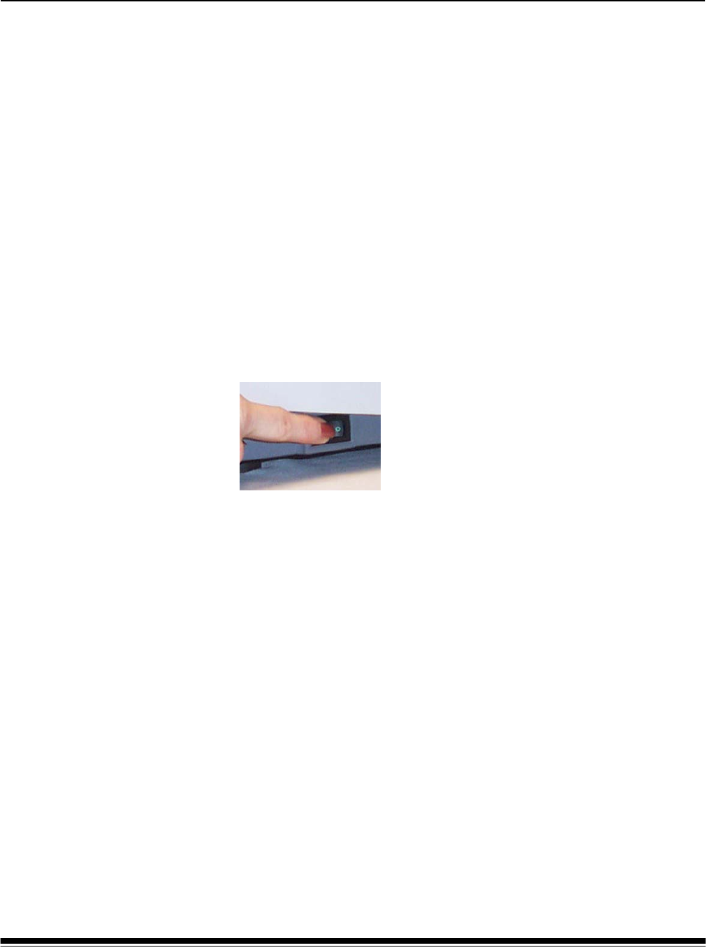
9 Power switch — press the power switch on (I) or off (O) as
required.
10 Exit deflector (optional) — aids in document stacking.
11 Paper Present Sensor — detects the presence of documents in
the elevator tray.
12* Height Adjustment Wire — located underneath the output tray
(not shown in photo), this wire can be pulled out to raise the front of
the output tray.
Stop/Pause (white with red triangle) button:
press once to temporarily pause scanning (the
green button can then use used to resume
scanning). Press twice to stop scanning
(end of job).
Start/Resume (green) button: to start scanning.
A-61500 April 2007 2-5
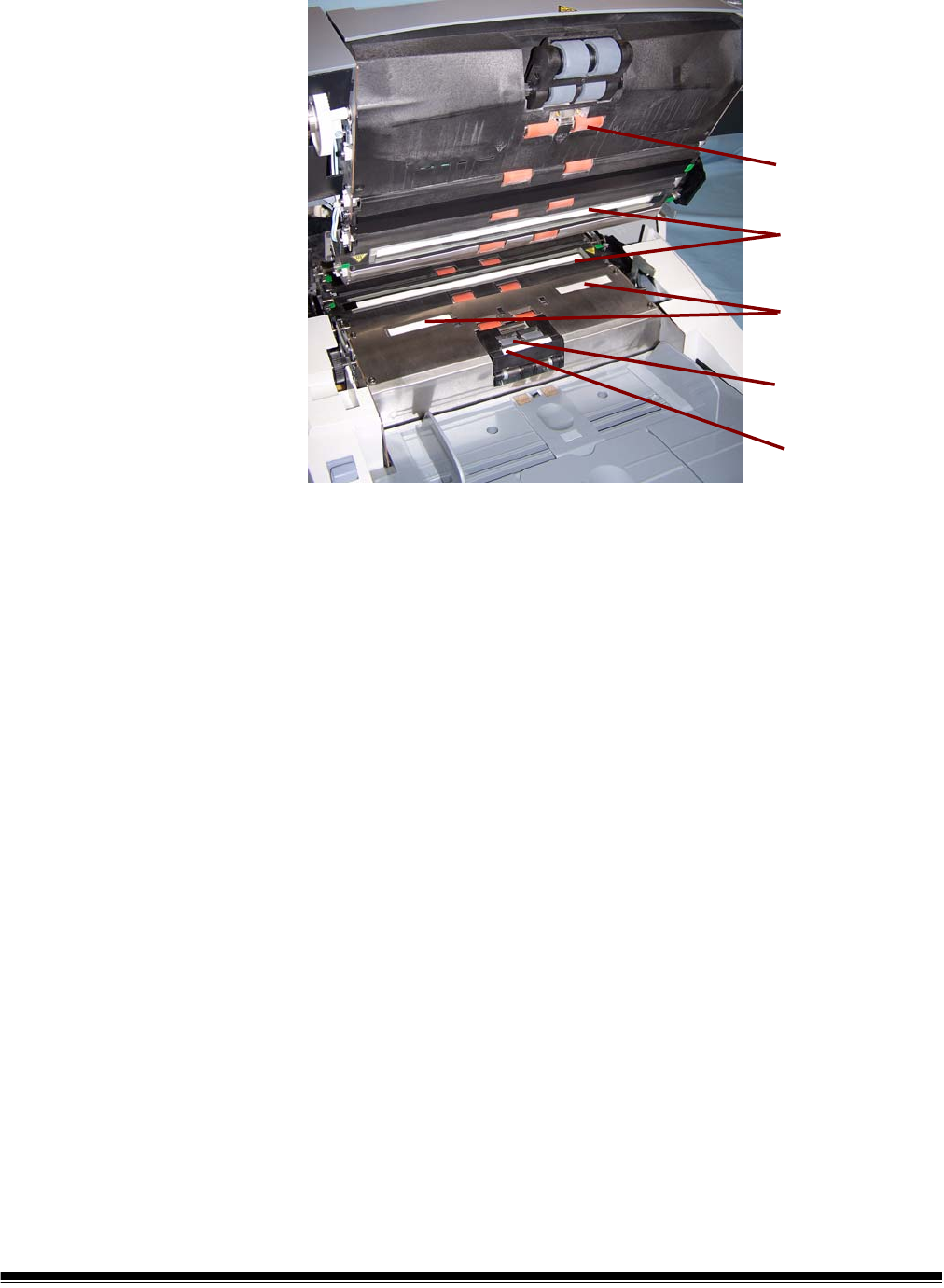
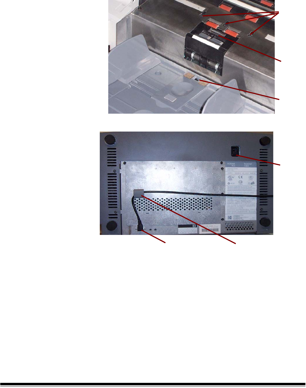
Internal components
Separation roller — provides smooth document feeding of various
sizes and textures one document at a time.
Ink blotter strips — collects residue from the Enhanced Printer.
Imaging guides — the scanner has an upper and lower imaging guide.
It is important to keep the imaging guides clean to obtain optimum
image quality.
CAUTION:Hot surface, avoid contact.
Rollers — drive rollers and NFR rollers transport the documents
through the paper path.
Pre-separation pad — provides smooth document feeding of various
sizes and textures one document at a time.
Rollers
Imaging guides
Ink blotter strips
Separation roller
Pre-separation pad
2-6 A-61500 April 2007
Sensors — the scanner has 3 (ultrasonic) multi-feed detection
sensors, 1 (optical) paper path sensor and 1 (optical) paper present
sensor. These sensors detect the presence of documents in the
elevator tray and documents in the paper path during feeding and
imaging.
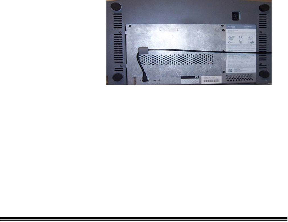
Rear view
Power Cord Connection — provides power to the scanner. The
scanner is packed with six power cords. Choose the power cord
appropriate for your location and connect it accordingly. Connect the
power cord first to the scanner, then to the wall outlet.
FireWire (IEEE-1394) Connection — before connecting the FireWire
cable, be sure that power to the scanner is off. See the FireWire
instructions packed with the scanner for connection instructions. After
connection, place the cable in the retainer clip located above the
connector.
sensors
Ultrasonic
Paper
Path
sensor
Paper
Present
sensor
Power
cord
connection
IEEE-1394 connection Retainer clip
A-61500 April 2007 3-1
3 Using the Scanner
This chapter provides the following operational procedures:
• Turning on/off the scanner
• Starting, stopping, pausing and resuming the scanner
• Document preparation
• Adjusting the side guides and output tray
• Scanning documents
• Feeding long documents
• Automatic, continuous and manual feeding
• Calibration
Turning the scanner
on and off
• Press the button on the scanner’s lower right-side (I) to power it up.
• Press the button on the scanner’s lower right-side (O) to power it
down.
After you power up the scanner, wait until for it to complete self-test.
When completed, the top green indicator light will remain on and
constant. If this does not occur, refer to Chapter 6, “Indicator lights” for
more information.
IMPORTANT: Always power up the scanner to its ready state before
powering up or restarting the host computer.
Starting and stopping
scanning
Scanning is controlled by integration software developed for your
application. To start and stop scanning, refer to the documentation
provided with your integration software.
If your application does not automatically start the scanner transport,
begin the scanning process by pressing the Start/Resume button on
the scanner.
NOTE: Before you start scanning, make sure the scanner is ready for
operation, which is indicated by the top green indicator light
being on and constant.
3-2 A-61500 April 2007
Manually pausing
and resuming the
scanner
While scanning documents:
• Press the Stop/Pause button on the scanner once to pause
scanning.
NOTE: Your application may configure the scanner with a transport
timeout function which signals an End of Job. If you do not start/
resume scanning before the timeout expires, you cannot
continue scanning without restarting the job from the host
application.
• Press the Start/Resume button on the scanner to restart scanning
after it has been paused.
Automatically
pausing and
resuming the
scanner
During scanning the scanner monitors its own internal image buffer
memory. In order to prevent overwriting images before the host
computer can retrieve them, the scanner will automatically pause the
feeder while waiting for the host computer to read existing images.
The scanner automatically resumes scanning by restarting the feeder
once image buffer memory is cleared. To avoid this situation be sure
your host computer meets the minimum system requirements as
referred to in Chapter 2.
Manually ending
scanning
After feeding the last document to be scanned, you can end scanning
by pressing the Stop/Pause button on the scanner twice. An end of job
message will be sent to your host application.
You cannot continue scanning without restarting the job from the host
application.
Start/Resume
Stop/Pause
button
button

A-61500 April 2007 3-3
Document
preparation
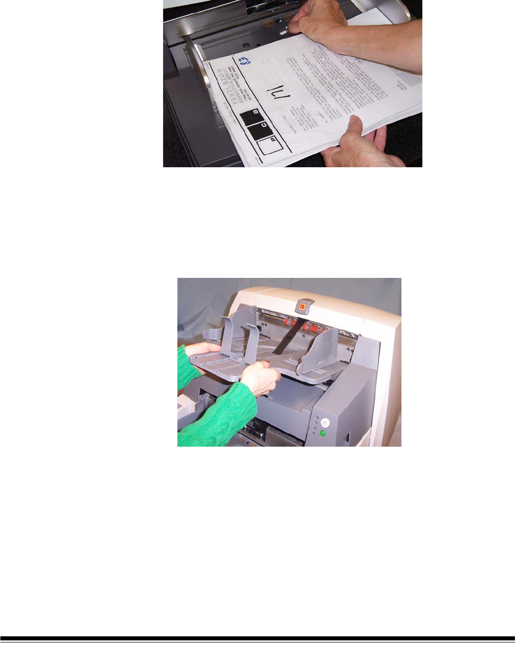
Before you begin scanning documents, make certain the documents
can be fed through the scanner easily.
• A batch of documents to be fed into the scanner must be arranged so
the leading edges of all documents are aligned and centered under
the feed module; this allows the feeder to introduce documents into
the scanner one at a time.
• Staples and paper clips in documents may damage the scanner and
documents. Remove all staples and paper clips before scanning.
• Documents with missing corners, perforated edges, hole punches in
the margins, irregular and curled edges, torn, damaged, or crushed
pages can be transported successfully through the scanner.
However, no scanner can transport every possible type of damaged
paper. If in doubt about whether a specific damaged document can
be transported through the scanner, place the document in a clear
protective sleeve with the lead edge of the document aligned with the
folded edge of the sleeve. Sleeves should be manually fed, one at a
time, folded edge first, while using the gap release lever. Ultrasonic
multi-feed detection is not recommended when using plastic sleeves.
NOTE: When scanning documents in a clear protective sleeve, the
elevator tray side guides must be aligned to accommodate the
width of the sleeve.
Kodak scanners have been tested with a range of documents that
represent the broad spectrum of document types found in the most
common business applications. Optimal scanner performance is
achieved when scanning documents within the recommended
document specifications listed below. Scanning documents outside of
these specifications may lead to undesirable results in terms of scanner
reliability, image quality, and/or consumable life.
Materials:
• Virgin, recycled and photographic papers
• Clear protective sleeves meeting the size and thickness
requirements in this section
Paper Types: Bond, Laser, Inkjet, Offset
Paper Weights: The elevator tray handles a broad range of paper
weights from 45 to 200 g/m2 (12 to 110 lb.). The Kodak Feeder Kit for
Ultra Lightweight Paper can handle paper weights from 25 to 75 g/m2
(7 to 20 lbs).
Minimum Document Size: 6.4 x 6.4 cm (2.5 x 2.5 in.). Documents as
small as 5 cm (2 in.) (i.e. business cards) can be center-fed, in portrait
orientation one at a time.
3-4 A-61500 April 2007
Maximum Document Size: 30.5 x 86 cm (12 x 34 in.). Documents
larger than 43 cm (17 in.) require operator assistance.
Paper inks: All inks on the paper must be dry before scanning is
started. This includes: Standard offset printing, Inkjet printer, Thermal
transfer, Handwriting inks.
Correction Fluids: Liquid Paper®, Tipp-Ex®, Wite-out®, and other
similar correction fluids.
Feeder Capacity: The elevator tray can hold up to 500 sheets of
75 g/m2 (20 lb.) paper.
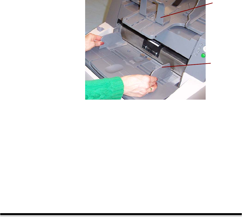
Adjusting the side
guides and end stop
To accommodate multiple applications with variable feeding
requirements, the side guides can be adjusted for right-, left- or center-
edge feeding. The side guides can be moved together or independently
to achieve offset feeding.
1. Pull the side guides all the way out and then push them together
(toward the center) to reset or center them.
2. Open the side guides slightly wider than the documents you will be
feeding.
3. Adjust the output tray end stop to slightly longer than the longest
document being fed in a batch.
4. Place the documents in the elevator tray.
5. Adjust the side guides to fit the documents.
End stop
Side guides
A-61500 April 2007 3-5
Locking the side guides Side guides may be locked into position after they are adjusted. This
may be helpful when the placement of print strings is important.
If you want to lock the side guides into position, move any documents
which may be in the input tray and move the locking switch into the
locked position.
Adjusting the back of
the output tray
Different paper types stack differently. The output tray can be set in
either one of two positions. In addition, you can raise the front of the
output tray to lift the front edge of the documents.
To raise or lower the back of the output tray:
1. Lift the front of the output tray and pull it out of the detent position.
2. Set the back of the tray either in the upper position or lower position
as desired.
3-6 A-61500 April 2007
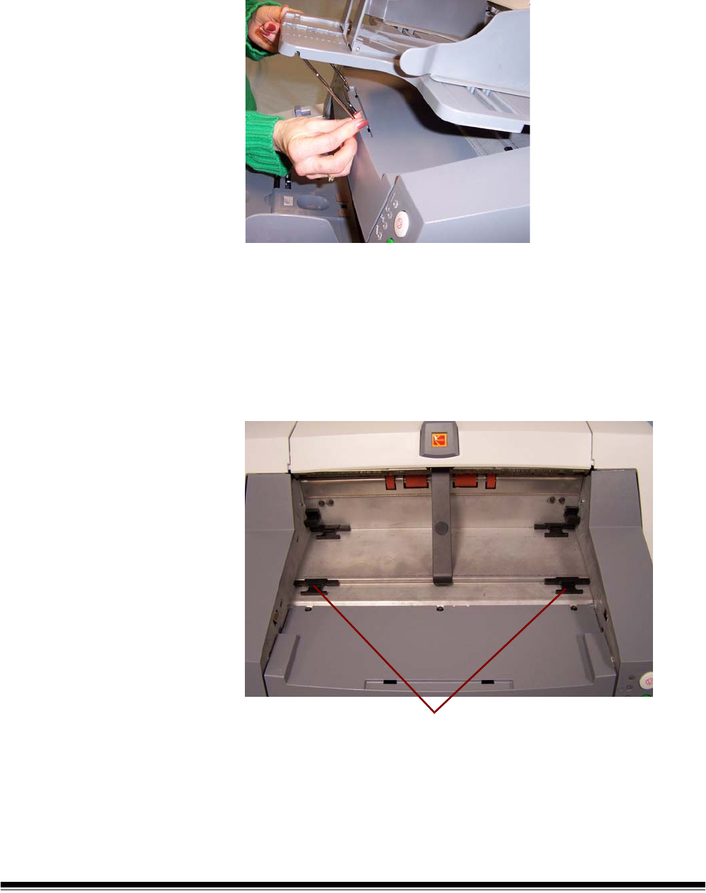
Adjusting the front of
the output tray
To raise the front of the output tray:
1. Lift the front of the output tray.
2. Swing the height adjustment wire out from underneath the output
tray and insert it into the groove on the printer access cover.
3. When finished using the output tray in this position, tuck the height
adjustment wire back into position and lower the output tray.
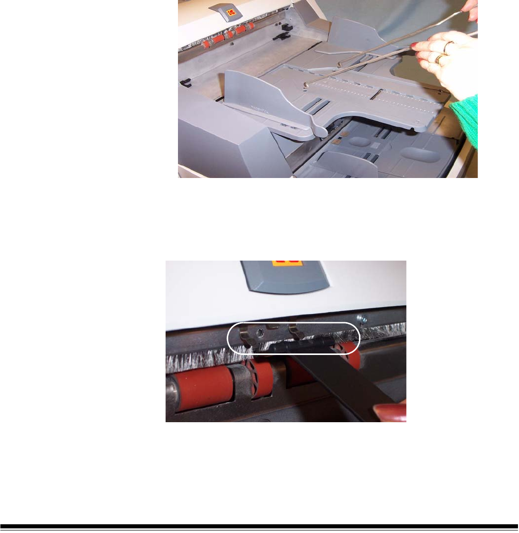
Adjusting the output
tray for long
documents up to 43
cm (17 in.)
To adjust the output tray to accommodate long documents from 37 cm
14.5 in.) to 43 cm (17 in.):
1. Lift the front of the output tray and pull it out of the detent position.
2. Place the output tray in the forward detent position.
3. Gently push down on the left side of the output tray until in snaps
into place.
4. Adjust the output tray end stop to accommodate long (or short)
documents by pulling the end stop forward (or backward).
5. Remove the exit deflector.
Forward detent positions
A-61500 April 2007 3-7
Adjusting the output
tray for documents
from 43 cm (17 in.) to
86 cm (34 in.)
An output tray document extender is available for scanning documents
from 43 cm (17 in.) to 86 cm (34 in.). Contact your Kodak Field
Engineer (1-800-3KODAK3) to order the document extender (Part No.
5E4754).
1. Lift the front of the output tray and pull it out of the detent position.
2. Place the output tray in the forward detent position.
3. Gently push down on the left side of the output tray until in snaps
into place.
4. Remove the end stop.
5. Remove the exit deflector.
6. Install the output tray document extender.
Exit deflector The optional exit deflector aids in document stacking. When feeding
long documents, it is suggested that the exit deflector be removed.
The exit deflector can be pulled out of place or pushed into place as
required.
3-8 A-61500 April 2007
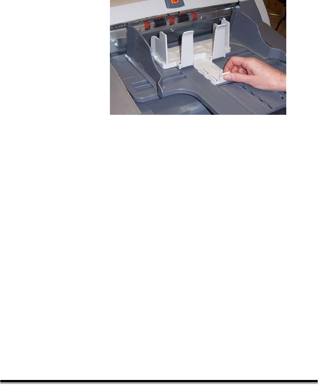
Adjusting the
optional short
document tray
A short document tray is available for scanning smaller documents.
This tray can be ordered from Parts Services. See Chapter 5, “Supplies
and Consumables” for ordering information.
1. Remove the end stop on the output tray.
2. Slide the short document tray on the rail of the output tray and push
it up to the desired position to accommodate your documents.
3. Adjust the side guides as necessary.
A-61500 April 2007 3-9
Feeding documents
using multi-feed
detection
The scanner has three multi-feed detection sensors. When Multi-feed
detection is enabled, adjust the side guides so the documents fully
cover at least one sensor. If the document partially covers a sensor,
false multi-feeds may occur.
Automatic feeding To scan a batch of documents follow the guidelines for size, type,
quantity, etc., outlined in the “Document preparation” section.
For faster throughput, place documents into the elevator tray in
landscape orientation (longer side as the leading edge).
IMPORTANT: Staples and paper clips on documents may damage the
scanner. Remove all staples and paper clips before
scanning.
1. Align the leading edges of the stacked documents.
2. Position the stack of the documents, face up in the elevator tray so it
covers the paper present sensor.
3. Adjust the elevator tray side guides.
4. Adjust the output tray position, if necessary.
5. Adjust the output tray end stop, if necessary.
Depending on how your scanner is set up, your documents will
automatically start scanning, or you may need to press the Start/
Resume button to begin scanning.
Continuous feeding Continuous feeding can be used when you want to scan small batches
of documents (less than 25).
When the scanner is configured for continuous feeding, the elevator
tray is raised to a position where approximately 25 documents can be
loaded. The elevator tray will remain in this position to allow more
documents to be loaded to the bottom of the stack.
To continuously feed documents, follow Steps 1 through 5 above. As
the documents are being scanned, you can continuously add a batch of
documents to the bottom of the stack.
NOTE: Depending on how your scanner is configured, the transport will
stop when the Transport Timeout has been reached.
3-10 A-61500 April 2007
Manual feeding To manually feed documents:
1. Position the document you want to feed in the elevator tray so that
the paper present sensor is covered.
2. Press Start/Resume.
Feeding documents
that require special
handling
The gap release lever allows you to manually adjust the space between
the feed module and separation roller for documents that require
special handling; i.e. documents that are badly torn. If you are in doubt
about whether a damaged document can be transported through the
scanner, use the gap release lever and manually feed the document.
Using the scanner in continuous feed mode is recommended when
handling special documents.
1. Press and hold the gap release lever — this provides clearance to
ease document feeding.
2. Push the document into the elevator tray. If more than one
document is to be scanned, feed them one at a time.
3. After the document(s) has been fed, release the gap release lever.
A-61500 April 2007 3-11
Calibrating the
scanner
There are two types of calibration that can be performed on the i600
Series Scanners: Image calibration and Ultrasonics calibration.
•Image calibration: optimizes the optical system in your scanner in
order to achieve the best overall quality of scanned images. Frequent
calibration is not needed or recommended.
IMPORTANT: If the White Background Accessory is installed, it must be
replaced with the black background strip, and the
scanner must be rebooted prior to calibration.
•Ultrasonics calibration: ensures that the ultrasonics system that
detects multi-feeds and document edges is properly adjusted for best
performance. Frequent calibration is not needed or recommended.
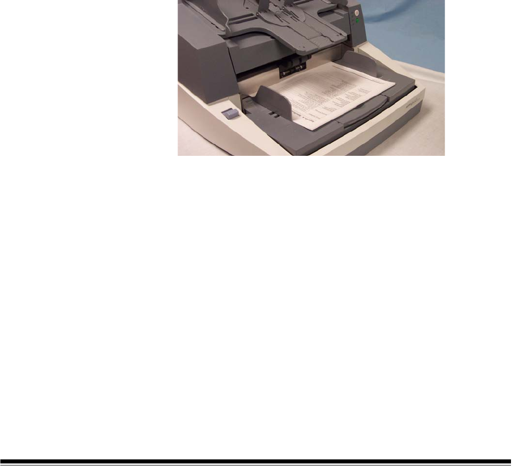
Image calibration Use the calibration target provided with your scanner. Be sure to use a
good, clean calibration target. Additional calibration targets can be
ordered. See Chapter 5, “Supplies and accessories” for ordering
information.
NOTE: The screens shown in this section are for the TWAIN
Datasource. The screens displayed on your system may be
different.
1. Open the pod and clean the imaging guides. Refer to the
maintenance procedures in Chapter 5.
2. If the lamps have not been on, allow the lamps to warm up for 90
seconds.
3. Center the side guides in the elevator tray and output tray.
4. Place the calibration target in the elevator tray.
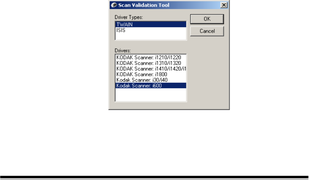
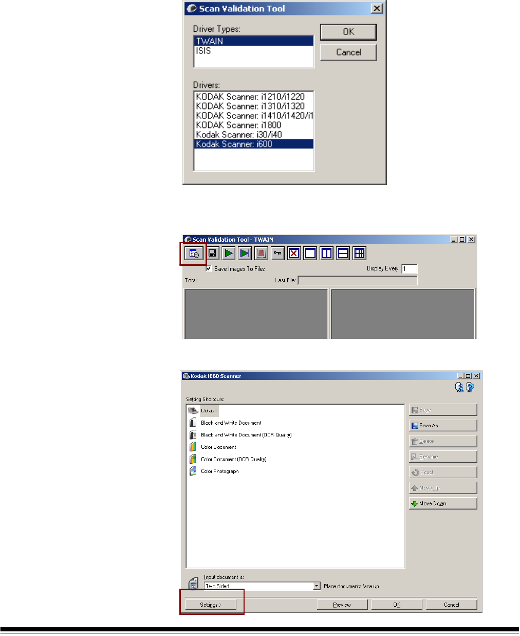
5. Open the Scan Validation Tool.
6. Select Kodak Scanner: i600.
3-12 A-61500 April 2007
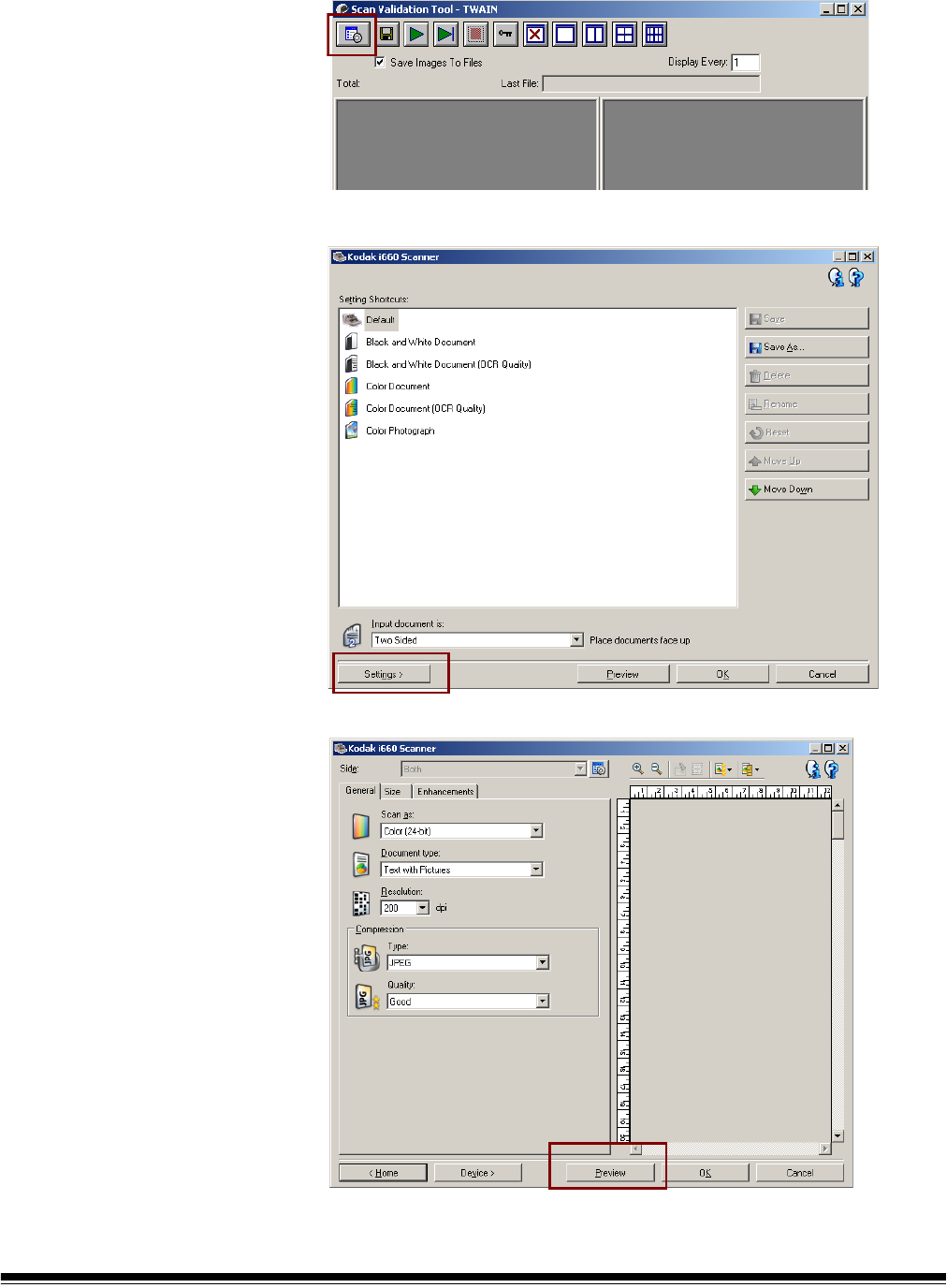
The main Kodak Scanner window will be displayed.
7. Click the Setup icon to access the main Kodak Scanner window.
8. Click Settings. The following screen will be displayed.
9. Click Device.
A-61500 April 2007 3-13
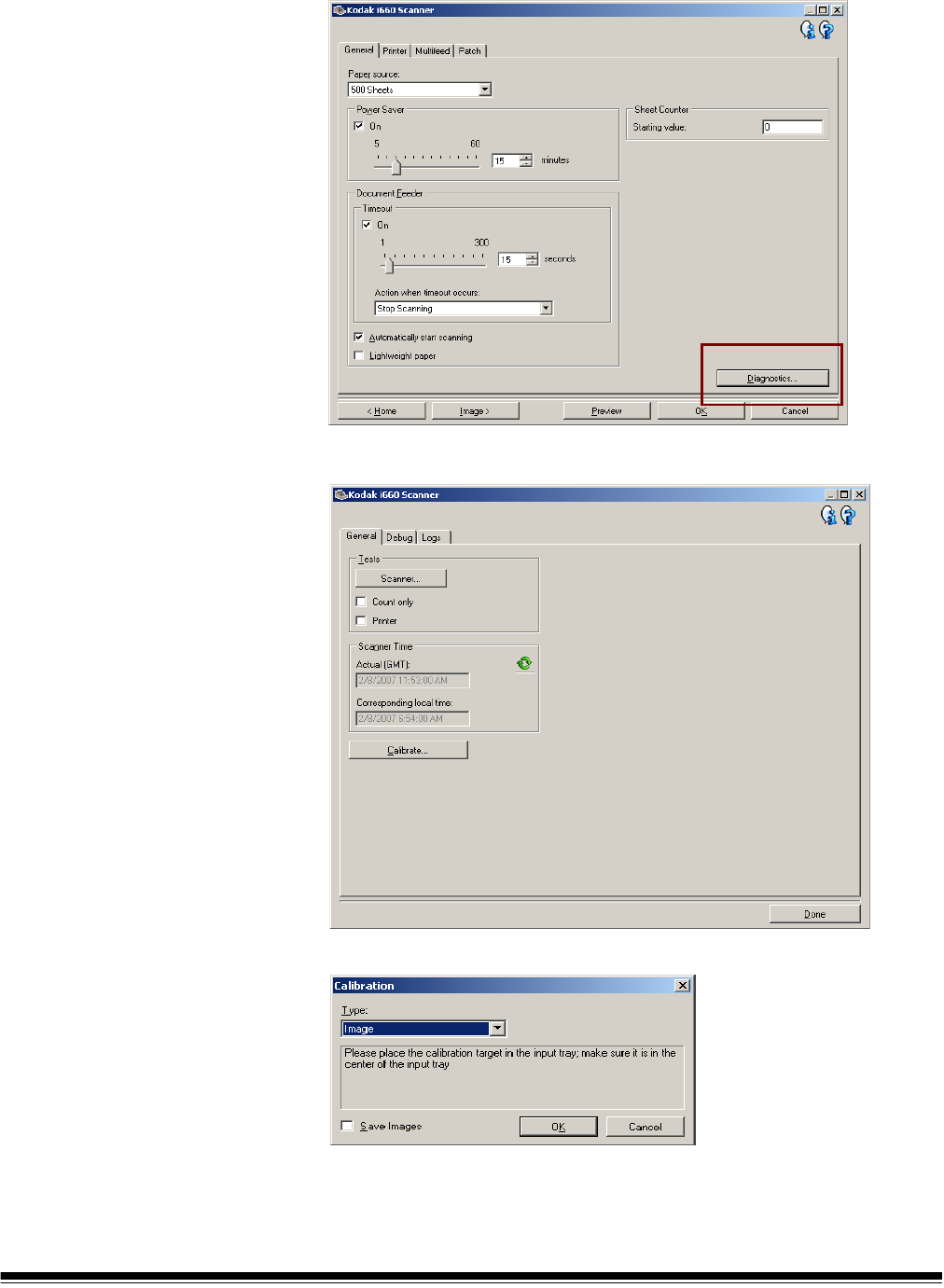
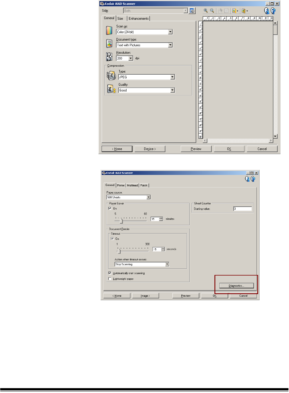
The following screen will be displayed.
10.Click Diagnostics. The following screen will be displayed.
11. Click Calibrate.
12.Select Image. Calibration begins. A confirmation box is displayed
when calibration is complete.
13.Click OK.

3-14 A-61500 April 2007
NOTE: If calibration fails, check the Operator Log for details. See
Chapter 6, “Accessing the Operator Log” for more
information. You must wait at least 90 seconds before
calibrating again.
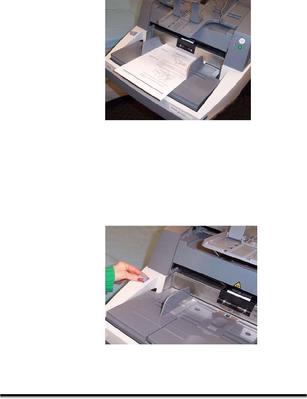
Ultrasonics calibration Use only an A4 size / 75-80 g/m2 or lettersize / 20 lb. bond paper to
perform an Ultrasonics calibration.
NOTE: The screens shown in this section are for the TWAIN
Datasource. The screens displayed on your system may be
different.
1. Center the side guides in the elevator tray and output tray.
2. Place the paper in the elevator tray in portrait orientation.
3. Follow Steps 5 - 12 above to access the Calibration dialog box.
4. Select Type: UDDS. Calibration begins. A confirmation box is
displayed when calibration is complete
5. Click OK.
NOTE: If calibration fails, check the Operator Log for details. See
Chapter 6, “Accessing the Operator Log” for more
information.

A-61500 April 2007 4-1
4 The Enhanced Printer
This chapter provides instructions for using the Enhanced Printer. The
following information and procedures can be found in this chapter:
• Overview information about the Enhanced Printer, including
information about print fields and printer specifications.
• Setting horizontal printer positions.
• Replacing the ink cartridge and ink blotter strips.
NOTE: More detailed information on the Enhanced Printer can be found
in the Image Processing Guide, A-61504.
Overview The Kodak i600 Series Scanners include a factory-installed, pre-
configured front printer. The printer operates at full scanner speed. The
printer can add a date, time, document sequential counter, and custom
messages.
The printer is unique in that the document print string can be configured
to include both literal (static) information (i.e., information that stays the
same for each document, such as batch name or operator) and
dynamic information (i.e., information that may change for each page
scanned, such as the document sequential counter). The capture
software application controls static fields; any information that the
software allows you to enter can be sent to the printer.
All printer controls and functions are accessible through the ISIS Driver
or TWAIN Data source. Printing must be enabled or disabled for each
scan session.
NOTES:
• Clean the scanner’s paper path components daily when using the
printer.
• You cannot print on documents that are smaller than 10 cm (4 in.).
• The ink cartridge must be installed prior to powering on the scanner,
or it could result in errors when printing is attempted.

4-2 A-61500 April 2007
Printer specifications
Characteristic Description
Maximum lines 1
Maximum characters 40
Print locations (horizontal) 12 front manually set,
Print locations (vertical) Set by capture software application
Print orientation 0, 90, 180 or 270 degrees
Font size 2 selectable, Bold or Normal
NOTE: Not all languages can support a Bold
font based on the complexity of the
characters, such as half-width
Katakana.
Ink cartridge Black: HP-C6602A
Red: HP-C6602R
Green: HP-C6602G
Blue: HP-C6602B
Print side Front (pre-scan)
Minimum printing distance
from document lead edge
0.89 cm (0.35 in.)
Static fields available User-specified messages via capture
software application
Dynamic fields available Up to a nine-digit sequential document
number, date, four-digit time
Languages supported Any phonetic language (for example: Dutch,
English, French, German, Italian,
Portuguese, Spanish, Japanese (half-width
Katakana)
A-61500 April 2007 4-3
Changing print
positions
The horizontal print position can be changed manually.
Changing the front
horizontal print position
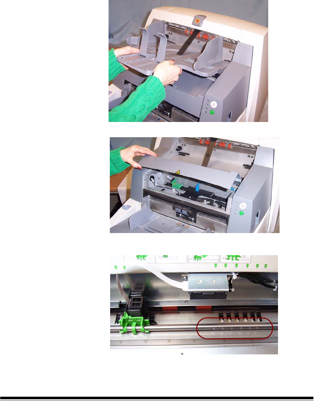
1. Remove the output tray.
2. Open the print access cover.
There are 12 horizontal print positions. These positions are visible
by a small detent on the printer rail.

4-4 A-61500 April 2007
3. The printer carrier slides easily along the rail. There is a small arrow
on the green printer carrier. Slide the printer carrier to the desired
position aligning the arrow with the detent position on the rail.
4. Close the printer access cover.
5. Reinstall the output tray.
NOTE: Printing automatically stops approximately ½-inch (1.27 cm)
from the trailing edge of the document, even if the information
has not been completely printed.
A-61500 April 2007 4-5
Replacing the ink
cartridge
Replace the ink cartridge when:
• printed characters appear light or uneven
• missing characters are evident
• a print test reveals inconsistent character quality
• cleaning has not improved the overall print quality
1. Remove the output tray and lift the printer access cover.
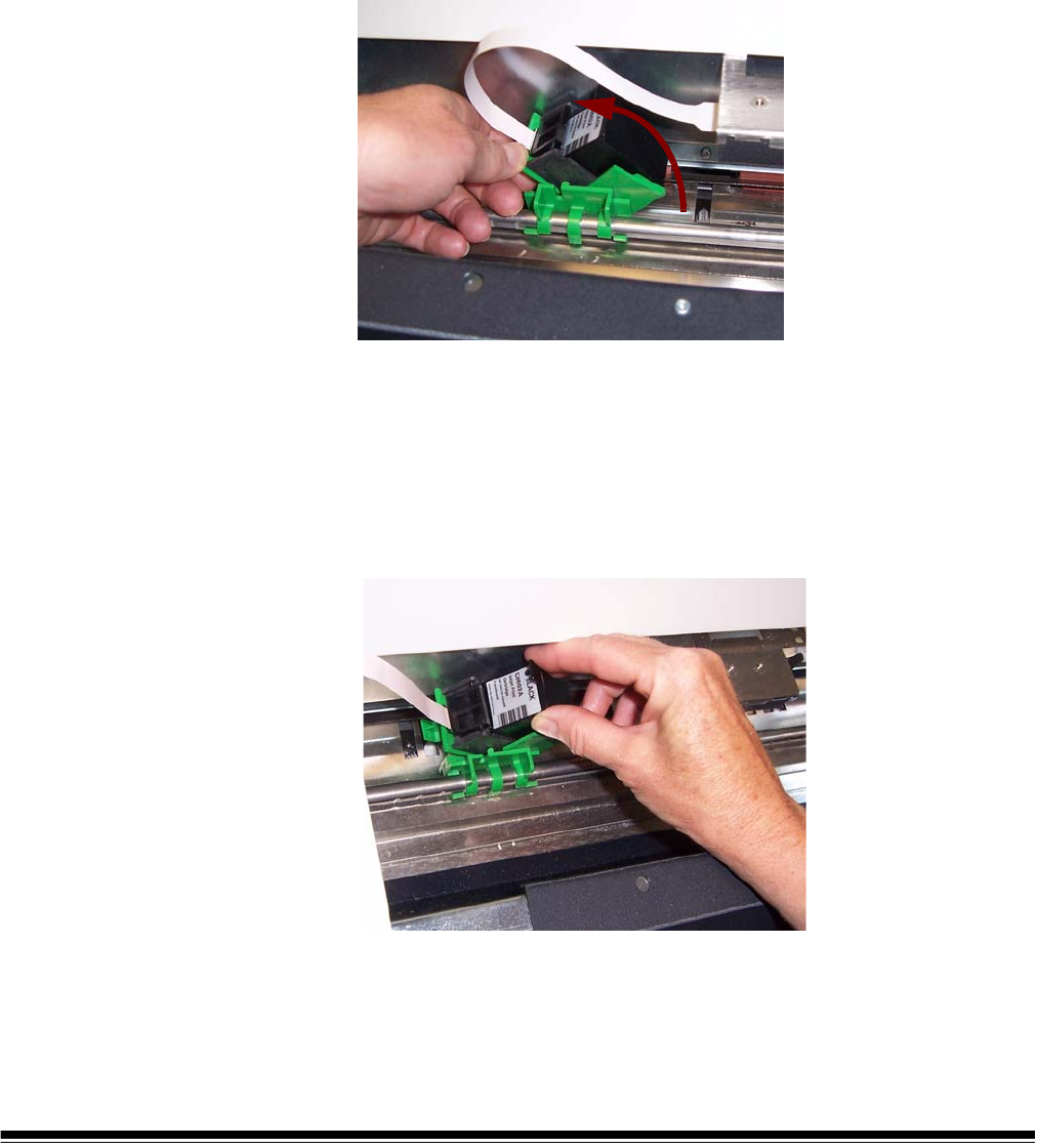
2. Holding the printer carrier as shown, press and hold the release tab
on the bottom of the printer carrier and rotate the printer carrier to
the left until it locks into position.
IMPORTANT: Dispose the empty ink cartridge in accordance with all
federal, state and local laws.
3. Lift the ink cartridge out from the printer carrier.
4. Remove the tab from the new ink cartridge.
5. Slightly angle a new ink cartridge in the print carrier and snap it into
place.
4-6 A-61500 April 2007
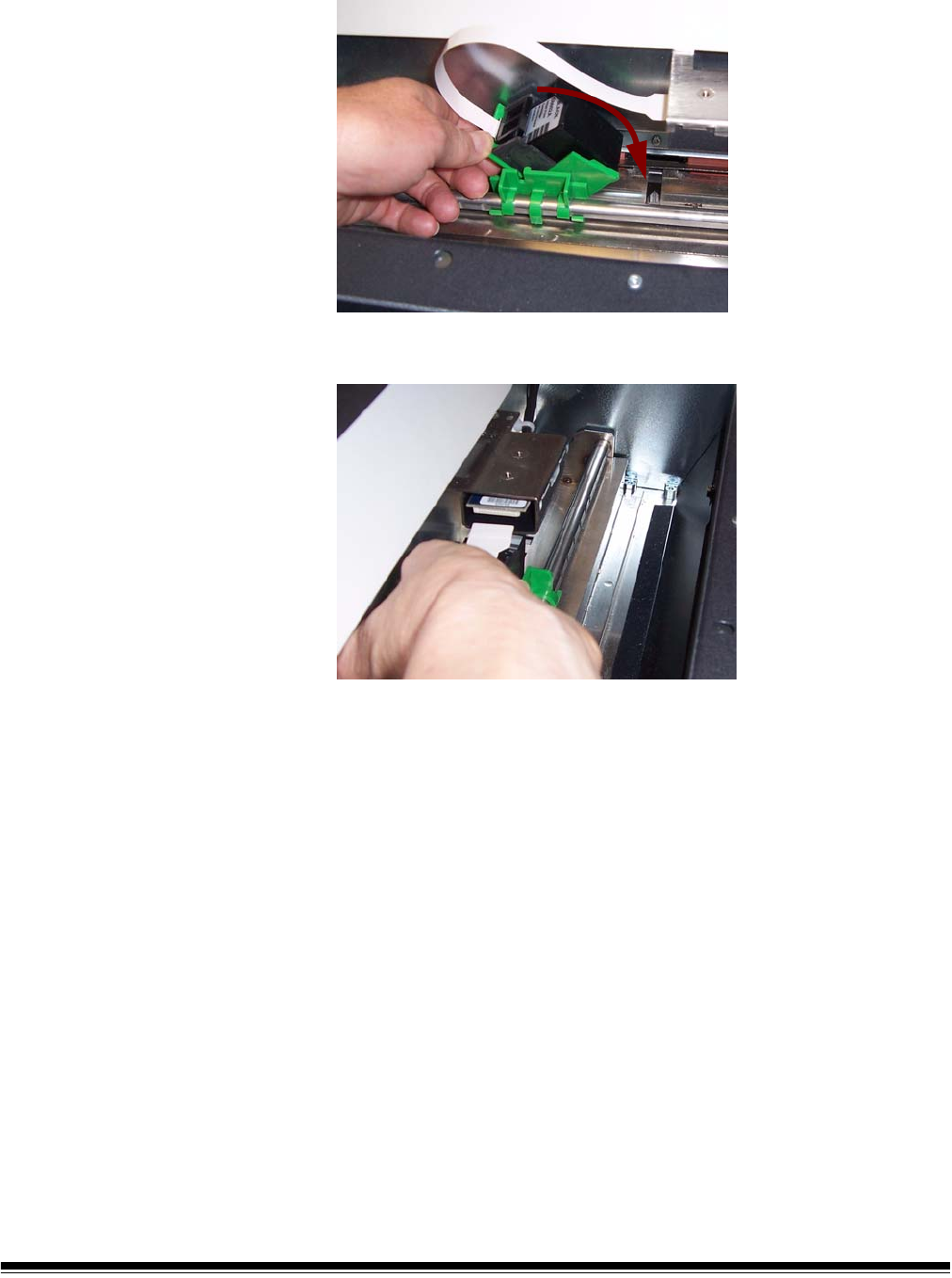
6. Press and hold the release tab on the bottom of the printer carrier
and rotate the printer carrier back into position.
NOTE: If the ribbon cable should become disconnected, snap it
back into position.
7. Slide the printer carrier into the desired position matching the arrow
on the printer carrier with the detent position.
8. Replace the output tray.
9. Run a print test.
A-61500 April 2007 4-7
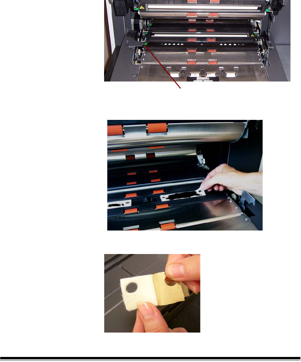
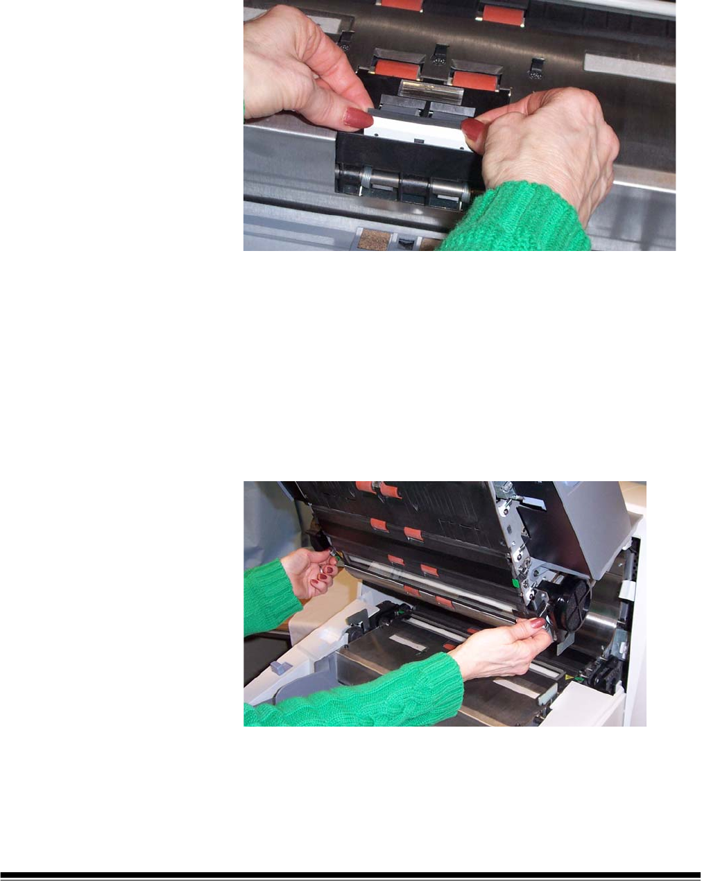
Replacing the blotter
strips
Blotter strips collect ink overflow. They should be replaced when there
is a build-up of ink. Replacement blotter strips may be purchased
through your supplier.
1. Open the pod.
2. Use the green tab to lift and remove the ink blotter strip cover to
access the front blotter strips.
3. Carefully pull the blotter strip(s) off the transport. You can replace
one or both of the strips as necessary..
4. Discard the soiled strip(s)
5. Peel the backing away from the blotter strip.
Remove Ink Blotter Strip cover

4-8 A-61500 April 2007
6. Align the blotter strip in the transport channel. Be sure it is properly
aligned before pressing the adhesive side into the channel.
7. Press the blotter strip firmly into the channel.
8. Repeat Steps 5 - 7 for the other blotter strip, if necessary.
9. Replace the ink blotter strip cover.
10.Close the pod.

A-61500 April 2007 5-1
5 Maintenance
This chapter provides:
• a cleaning frequency chart
• a list of cleaning tools and materials
• a list of supplies and accessories
• cleaning procedures for the scanner
• replacement procedures for parts that are customer-replaceable
IMPORTANT: Scanner components marked with a green tab indicate
operator-accessible parts.
Cleaning your scanner and preventative maintenance on a regular
basis is required to ensure the best possible image quality. The
following is a preventative maintenance procedure that is
recommended to prevent costly interruptions during production
scanning. Following this procedure as recommended should take
approximately 5 to 10 minutes.
Some document types generate more paper dust and debris and may
require more frequent cleaning than recommended.
NOTES:
• Some debris from the rubber tires on the feed module and separation
roller is normal. Tire debris does not always mean that the tires are
worn or damaged. After cleaning, inspect the tires for wear and
replace the separation roller or feed module if necessary.
• When cleaning rollers/tires, allow the rollers/tires to dry completely
before scanning.
• Using unapproved cleaning fluids or solvents may damage the rubber
tires.

5-2 A-61500 April 2007
Cleaning frequency
chart
A recommended cleaning sequence includes vacuuming the scanner
transport, cleaning the residue from the feed module, separation roller
or drive rollers and cleaning the imaging guides.
Use the chart below as a guide to how frequently you should clean your
scanner.
Cleaning tools and
materials
Use only these cleaning tools and materials when performing routine
maintenance on your scanner. Use of any other cleaning materials
could damage your scanner.
•Kodak Digital Science Transport Cleaning Sheets
•Kodak Digital Science Roller Cleaning Pads
• Staticide Wipes for Kodak Scanners
• A vacuum cleaner and tools
Procedure Start of
day
Middle of
shift
Start of new
shift
Vacuum output tray and input
areas (elevator and transport)
x
Clean all rollers xx
Vacuum transport area xxx
Remove and vacuum under
background strips
x
Remove and clean imaging
guides
xx
Vacuum under imaging guides xx
Run transport cleaning sheet xx
Wipe imaging guides with cloth xxx
A-61500 April 2007 5-3
Supplies and
accessories
Contact your scanner supplier to order supplies.
NOTE: Items and catalog numbers are subject to change.
Ordering parts The following parts can be ordered from Parts Services.
Item CAT No.
Kodak Feeder Consumables Kit for i600/i1800 Series
Scanners
108 4755
Kodak Feeder Kit for Ultralightweight Paper for i600/i1800
Series Scanners
896 5279
Kodak Extra-Large Feeder Consumables Kit for i600/i1800
Series Scanners
842 6157
Kodak Extra-Extra-Large Feeder Consumables Kit for i600/
i1800 Series Scanners
134 3680
Kodak Imaging Guide Set / for i600/i1800 Series Scanners 197 6703
Kodak Printer Ink Blotters, Front Side for i600/i1800 Series
Scanners
125 7633
Enhanced Printer Ink Carrier 113 3842
Enhanced Printer Black Ink Cartridge (qty 3) 818 3386
Enhanced Printer Red Ink Cartridge (qty 3) 159 6832
Enhanced Printer Ink Blotter Kit (qty 60) 140 1728
Kodak Digital Science Transport Cleaning Sheets (qty 50) 169 0783
Kodak Digital Science Roller Cleaning Pads (qty 24) 853 5981
Staticide Wipes for Kodak Scanners (qty 144) 896 5519
Kodak Calibration Targets (qty 5) 127 1436
Parts Part No.
Exit deflector 3E9575
Black Background 9E3357
26 in document extender (qty 1) 5E4754
30 in document extender (qty 1) 9E3216
34 in document extender (qty 1) 9E5277
Short document tray 9E5746
5-4 A-61500 April 2007
Cleaning procedure Follow the cleaning procedure below to ensure the best scanner
performance and image quality.
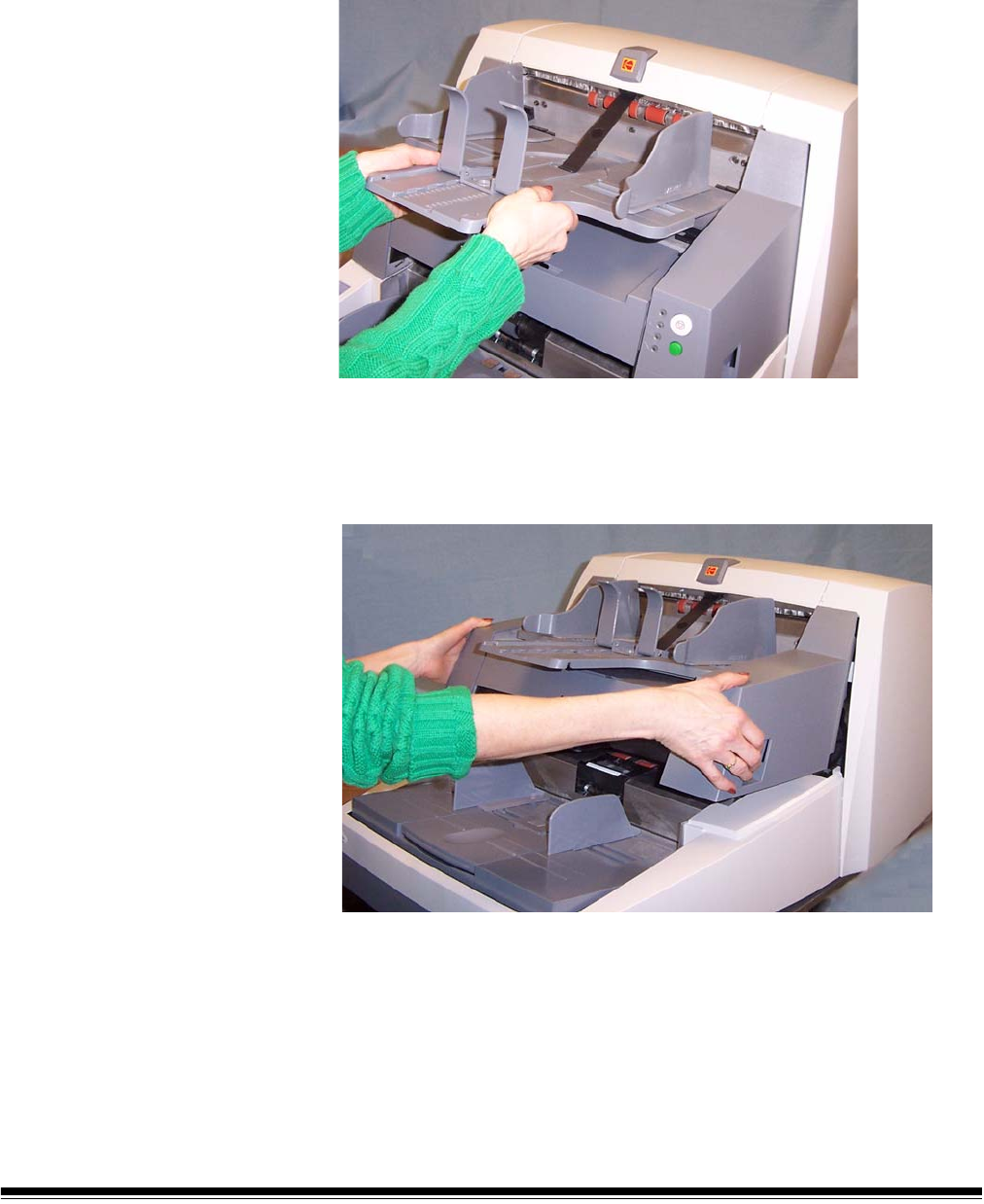
Cleaning the output tray and elevator area
1. Power down the scanner.
2. Remove the output tray.
3. Thoroughly vacuum the output tray area and the input area
(elevator) using a brush attachment of a vacuum cleaner.
Opening the pod
4. Push up on the pod release lever and open the pod.

A-61500 April 2007 5-5
Cleaning the drive rollers
5. Manually rotate and wipe the NFR and drive rollers with a roller
cleaning pad.
IMPORTANT: The roller cleaning pad contains sodium lauryl ether
sulfate and sodium silicate which can cause eye
irritation. Refer to the MSDS for more information.
6. Dry the rollers with a lint-free cloth.
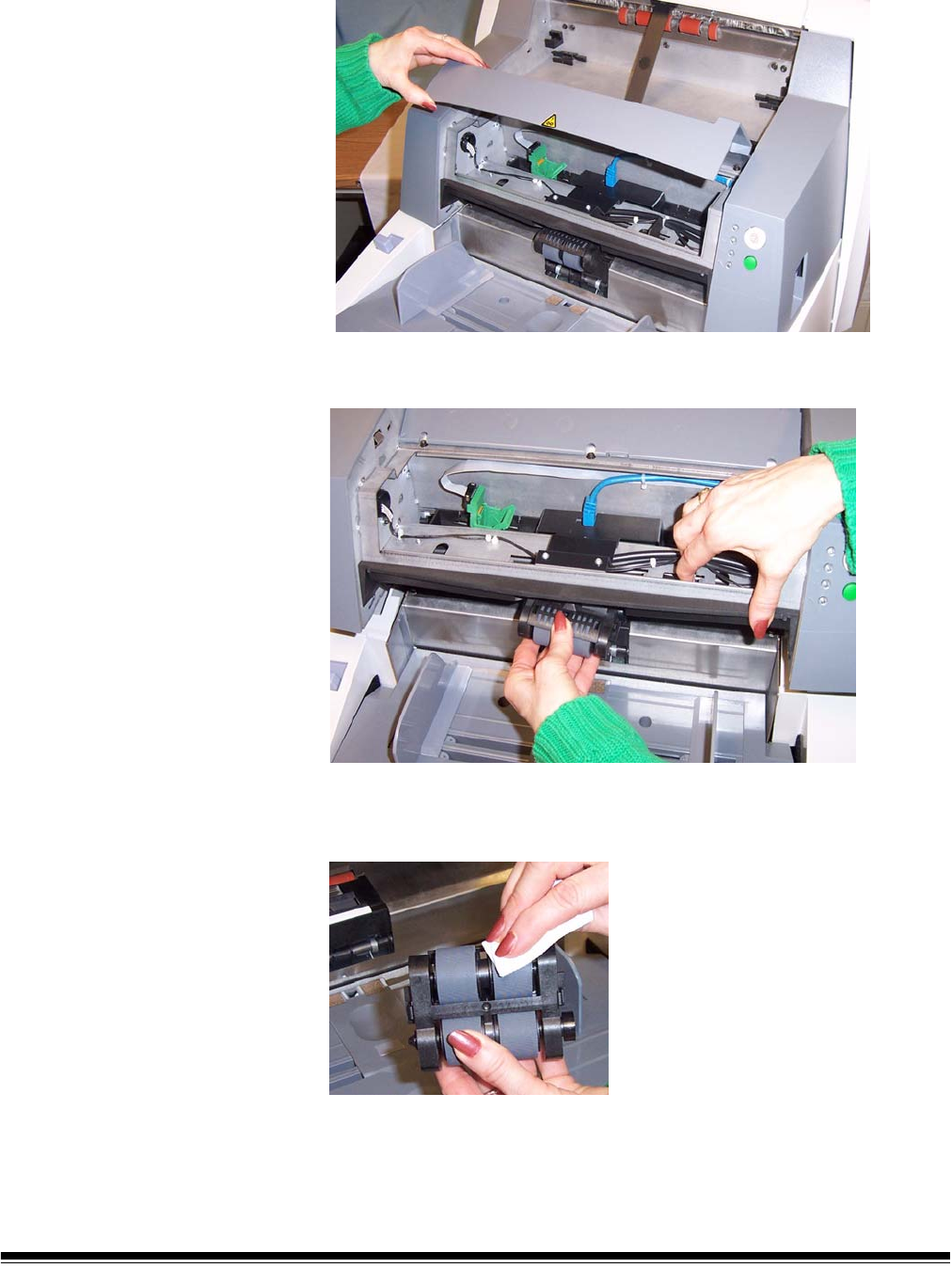
Cleaning the separation roller tires
7. Pull the separation pad holder forward and remove the separation
roller.
8. Manually rotate and wipe the separation roller tires with a roller
cleaning pad. For best results wipe parallel to the ribs in order to
remove any residue between the ribs.
9. Inspect the tires. If the tires show signs of wear or damage, replace
the separation roller. See “Replacement procedures” later in this
chapter.
10.Reinstall the separation roller.
5-6 A-61500 April 2007
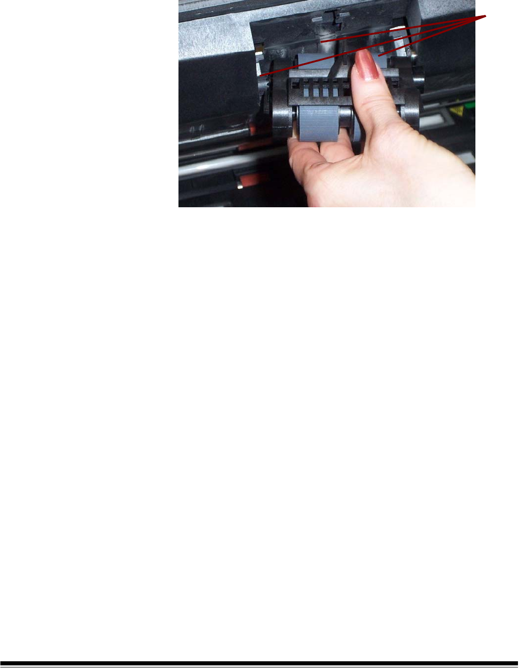
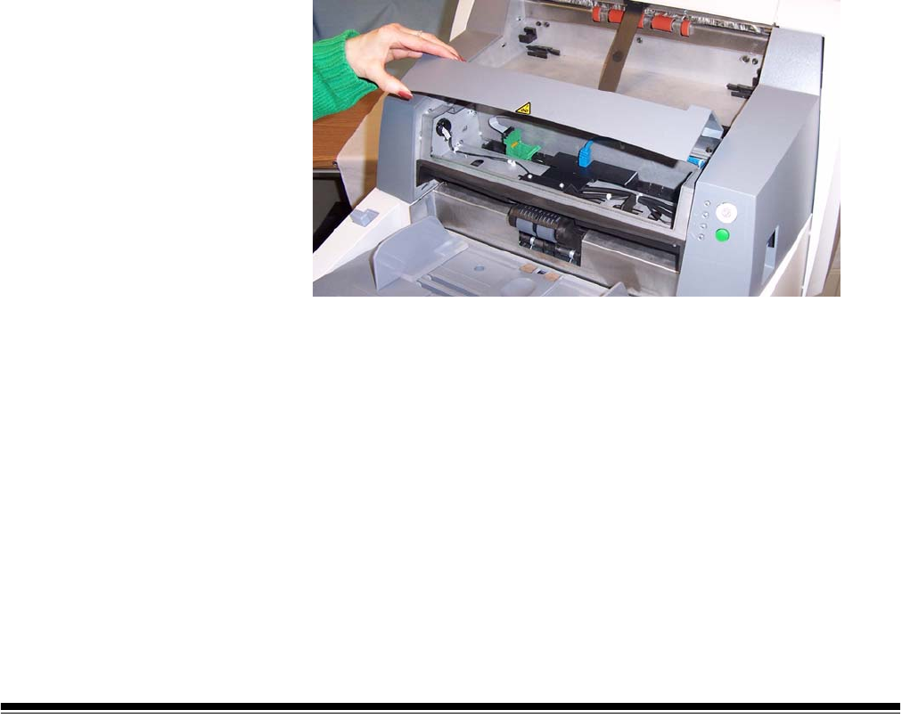
Cleaning the feed module tires
11. Lift up the printer access cover.
12.Push the release lever down (located underneath the printer access
cover) to release and remove the feed module.
13.Manually rotate and wipe the feed module tires with a roller cleaning
pad. For best results wipe parallel to the ribs in order to remove any
residue between the ribs.
14.Inspect the tires. If the tires show signs of wear or damage, replace
the feed module tires. See “Replacement procedures” later in this
chapter.
A-61500 April 2007 5-7
15.Reinstall the feed module by aligning the pins, fitting it into position
and pulling up on the release lever to lock it into place. Verify that
the feed module is securely in place and moves freely after you
install it.
16.Close the printer access cover.
Align
these
areas
5-8 A-61500 April 2007
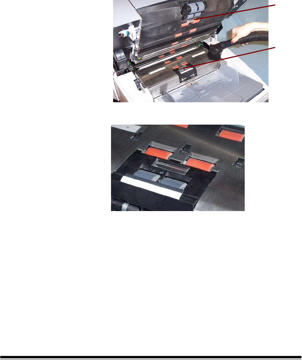
Cleaning the scanner transport area
17.Thoroughly vacuum the entire transport area, paying particular
attention to these areas:
• the edges of the transport
• the reflective tape near the front of the transport
• the reflective tape near the front of the pod
• the three paper path sensors at the base of the transport and the
pod
reflective
tape near
front of
pod
reflective
tape near
front of
transport

A-61500 April 2007 5-9
Cleaning the background strips
18.Using the green tabs pull off the upper and lower background strips
and set them aside.
19.Vacuum the areas where the background strips are adhered to.
20.Reinstall the upper and lower background strips.
Cleaning the imaging guides
21.Turn the screw on each end of the upper imaging guide, remove it
from its position and set it aside.
22.Turn the screw on each end of the lower imaging guide, remove it
from its position and set it aside.
Lower strip
Upper strip
Lower imaging guide

5-10 A-61500 April 2007
23.Carefully vacuum the areas between the lamps (both upper and
lower), then use a Staticide wipe to thoroughly clean the glass dust
plate between the lamps.
24.Clean the imaging guides thoroughly with a Staticide wipe.
IMPORTANT: Staticide wipes contain isopropanol which can cause eye
irritation and dry skin. Wash your hands with soap and
water after performing maintenance procedures. Refer to
the MSDS for more information.
25.Reinstall the upper and lower imaging guides. Handle the imaging
guides carefully as to not put fingerprints on the guides.
26.Close the pod.
27.Reinstall the output tray.
28.Power on the scanner.
A-61500 April 2007 5-11
Running a transport cleaning sheet
1. Place a transport cleaning sheet in the elevator tray in landscape
orientation.
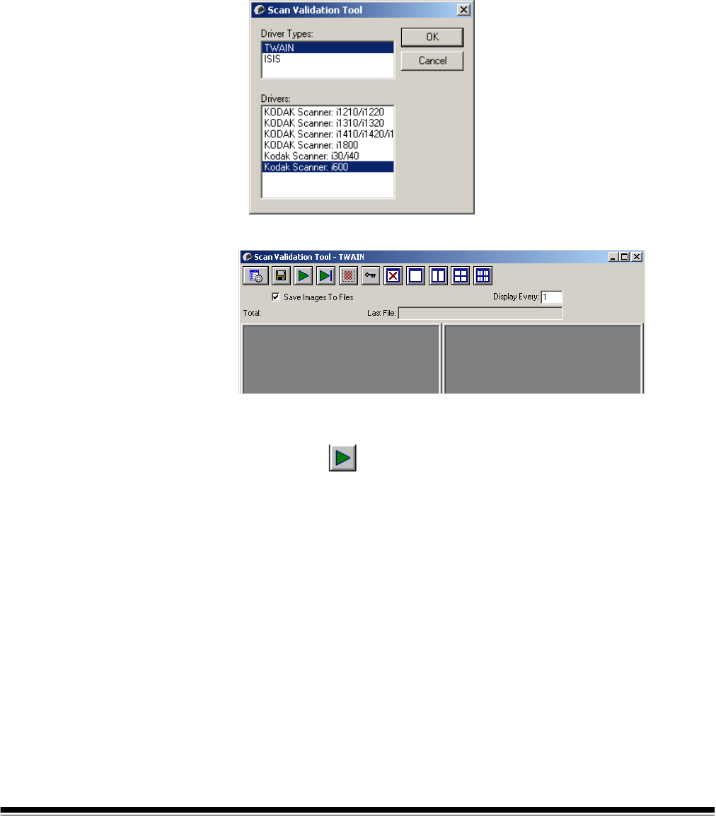
2. Open the Scan Validation Tool by selecting Start>Programs>
Kodak>Document Imaging>Scan Validation Tool. The Scan
Validation Tool dialog box will be displayed.
3. Select TWAIN (or ISIS) for the Driver Types and Kodak Scanner
i600 as the Driver and click OK.
The Scan Validation Tool dialog box will be displayed.
4. If Saved images to file is checked, uncheck it.
5. Click Start
6. After the transport sheet is scanned, turn it over and click Start
again.
7. Open the pod and wipe the imaging guides with a lint-free cloth.
8. Close the pod and check your image quality.
5-12 A-61500 April 2007
Replacement
procedures
This section provides procedures for replacing the following parts. Use
the list below as a guideline for frequency of replacement.
•Feed Module tires and Separation Roller tires — tire life will vary
depending upon paper types, environment and cleanliness. Nominal
tire life will be approximately 250,000 documents; results will vary.
Degradation of feeder performance, multiple feeds, stoppages, etc.
indicate a need to change tires. Change all the tires on the feed
module and separation roller at the same time.
•Feed Module and Separation Roller — it is recommended that you
install a new feed module and separation roller approximately every
4th tire change. Install a new feed module and separation roller at the
same time.
•Pre-separation Pad — it is recommended that you change the pre-
separation pad approximately every 250,000 documents.
•Imaging Guides — replace when the imaging guides are heavily
scratched and defects show in the image.
Replacing the feed
module or feed module
tires
To replace the feed module or feed module tires:
1. Remove the output tray.
2. Lift up the printer access cover.
3. Open the pod.
A-61500 April 2007 5-13
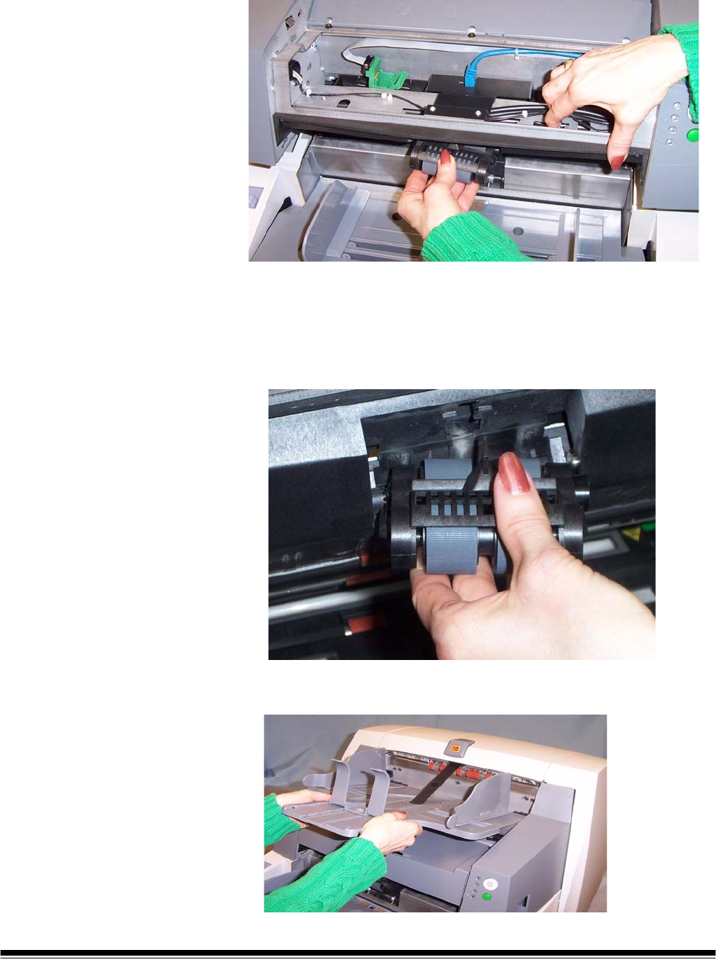
4. Push down on the release lever (located underneath the printer
access cover) to release and remove the feed module.
5. If you are just replacing the feed module:
• Insert the new feed module by aligning the pins, fitting it into
position and pulling up on the release lever to lock it into place.
Verify that the feed module is securely in place and moves freely
after you install it.
• Close the pod and the printer access cover.
• Reinstall the output tray.
5-14 A-61500 April 2007
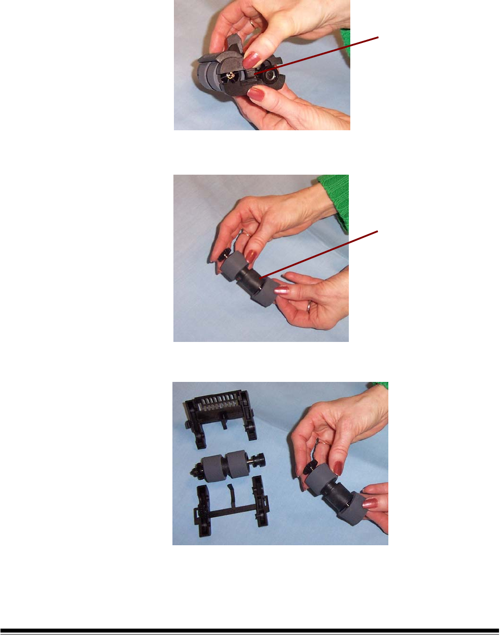
If you want to replace the tires, proceed as follows:
6. With one hand, press the locking tabs (one on each side) while
holding the bottom housing with the other hand, pull the upper
housing up and away from the rollers.
7. Remove one core assembly.
8. Replace each tire by sliding the tire off the core.
9. Install each new tire by gently pulling it over the core.
IMPORTANT:Do not overstretch the tire; it may tear.
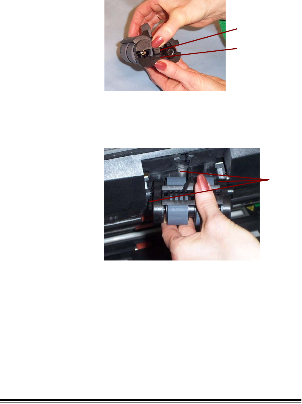
10.Replace the core assembly in the feed module.
11. Repeat the replacement procedure outlined above for the other core
assembly.
Locking tab
Core assembly
A-61500 April 2007 5-15
12.Align the tabs on the upper housing with the slots on the lower
housing.
13.Press the upper and lower housings together until they snap into
place.
14.Reinstall the feed module by aligning the pins, fitting it into position
and pulling up on the release lever to lock it into place. Verify that
the feed module is securely in place and moves freely after you
install it.
15.Close the pod.
16.Close the printer access cover.
17.Reinstall the output tray.
Locking tab
Slot
Align
these
areas
5-16 A-61500 April 2007
Replacing the separation
roller or separation roller
tires
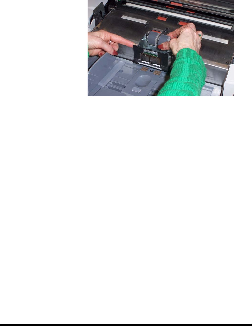
1. Open the pod.
2. Pull the separation pad holder forward and remove the separation
roller.
If you want to replace the separation roller, do Steps 3 and 4. If you
want to replace the separation roller tires, go to Step 5.
3. Insert the new separation roller. Be sure to line up the slots on the
separation roller with the holders.
4. Push the separation roller holder back in place and close the pod.
To replace the tires:
5. Replace each tire by sliding the tire off the core.
6. Install each new tire by gently pulling it over the core.
IMPORTANT:Do not overstretch the tire; it may tear.
7. Reinstall the separation roller. Be sure to line up the slots on the
separation roller with the holders.
8. Push the separation roller holder back in place and close the pod.
A-61500 April 2007 5-17
Replacing the pre-
separation pad
Change the pre-separation pad when the frequency of double-fed
documents increases.
1. Open the pod.
2. Remove the pre-separation pad.
3. Install the new pre-separation pad. Be sure it snaps into place.
4. Close the pod.
Replacing the imaging
guides
The imaging guides should be replaced when they are heavily
scratched and defects show in the image.
NOTE: Handle the imaging guides carefully as to not put fingerprints on
the guides.
1. Open the pod.
2. Turn the screw on each end of the upper imaging guide to remove it
from its position.
3. Install the new imaging guide and turn the screws to secure the
imaging guide.
4. Repeat Steps 2 and 3 to replace the lower imaging guide.
5. Close the pod.
A-61500 April 2007 6-1
6 Troubleshooting
This chapter provides:
• A description of the indicator lights located on the front of the
scanner.
• Information about accessing the Operator Log.
• A problem solving chart.
• A message listing of possible errors you may encounter while using
the scanner.
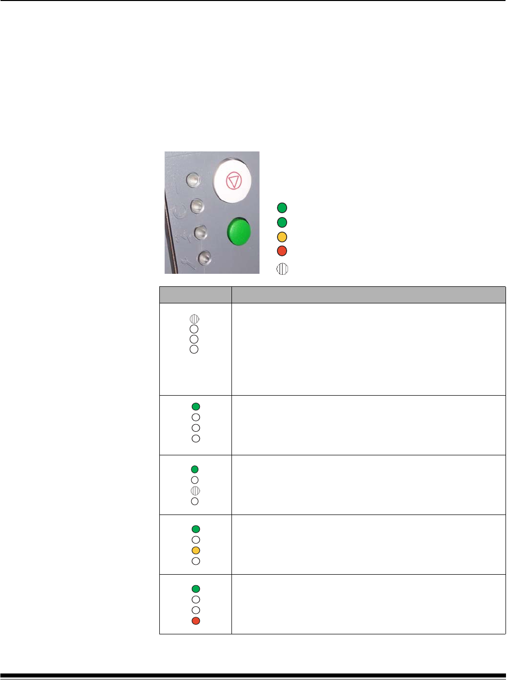
Indicator lights There are four indicator lights on the front of the
scanner. See the table below for LED meanings:
Led display Description
Scanner is in sleep or lamp saver mode.
To return to Ready state:
• press the Start/Resume button on the scanner or enable
scanning from the host, or
• add paper to an empty elevator tray, or remove paper from
the elevator tray.
Scanner is powered on and idle.
Scanner is idle and a document jam or multi-feed has been
detected. See Operator Log for details.
Scanner is idle and has detected a user-correctable error.
See Operator Log for details.
Scanner is idle and has detected a hardware/software error.
Cycle power on the scanner. If the condition persists, see the
Operator Log for details. If the condition cannot be cleared,
call Service.
= green, Power
= green, Ready
= yellow, Jam/User correctable
= red, Service/Error
LED indicators
= indicates when an indicator is flashing

6-2 A-61500 April 2007
Led display Description
Scanner is in sleep mode and has detected a hardware error.
Cycle power on the scanner. If the condition persists, see the
Operator Log for details. If the condition cannot be cleared,
call Service.
Scanner warm-up sequence.
Scanner is enabled. Start/Resume and Stop/Pause buttons
are available.
Scanner is enabled and scanning is allowed. Start/Resume
and Stop/Pause buttons are available, however a warning
condition has been detected. See the Operator Log for
details. (e.g., clean the imaging guides, calibrate the scanner,
etc.)
A-61500 April 2007 6-3
Accessing the
Operator Log
The Operator Log is accessed through the Scan Validation Tool.
1. Select Start>Programs>Kodak>Document Imaging>Scan
Validation Tool.
2. From the Driver Types box, select TWAIN.
3. Open the Scan Validation Tool.
4. Select Kodak Scanner: i600.
The main Kodak Scanner window will be displayed..
5. Click the Setup icon to access the main Kodak Scanner window..
6-4 A-61500 April 2007
6. Click Settings. The following screen will be displayed.
Click Device.The following screen will be displayed.
A-61500 April 2007 6-5
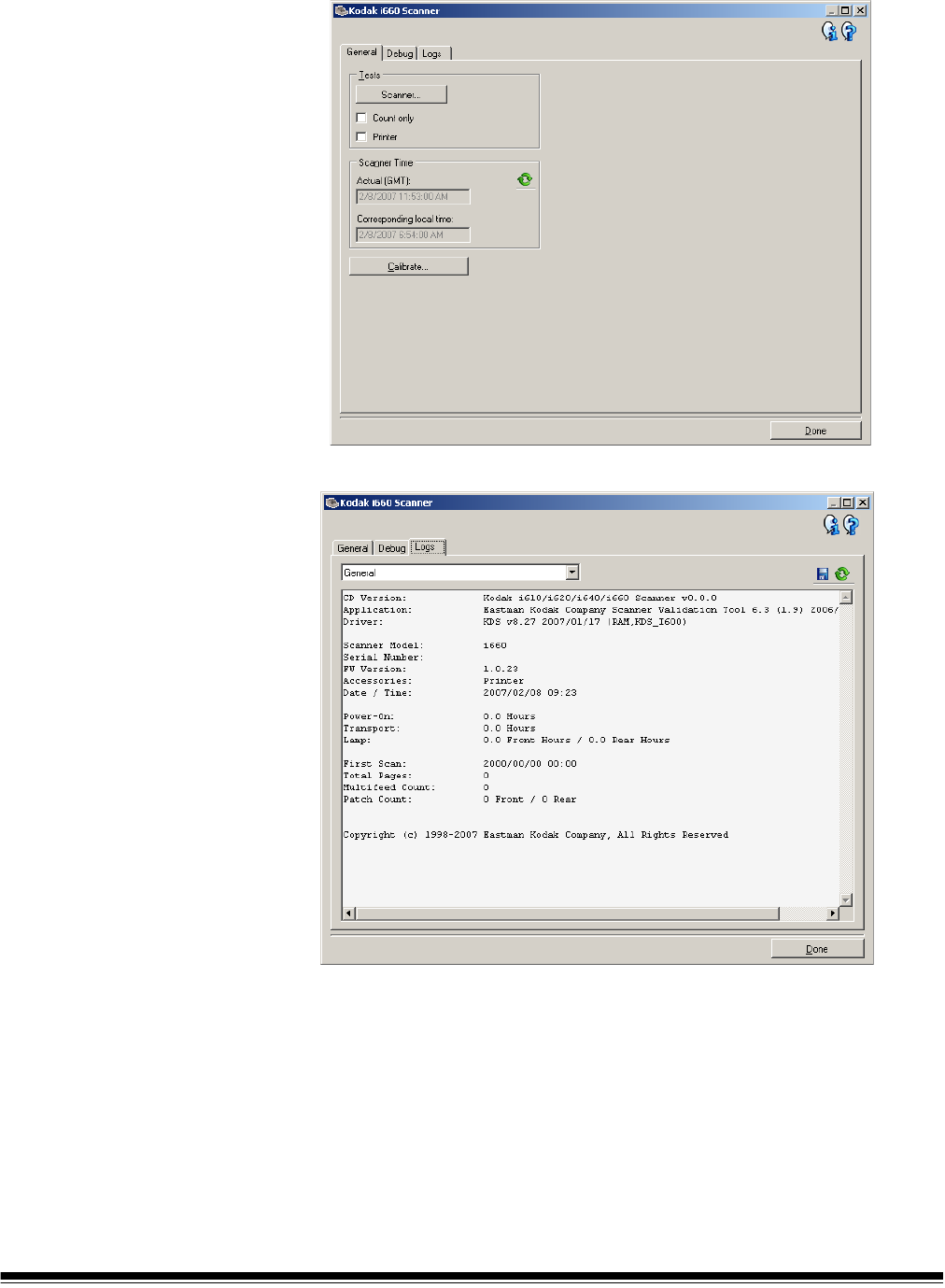
7. Click Diagnostics. The following screen will be displayed.
8. Click the Logs tab.
9. From the drop down box, select Operator to display the Operator
log. The most current log entries are displayed at the top of the list.
See the following Message Listing for an explanation of the error
condition.

6-6 A-61500 April 2007
Message listing Following is an alphabetic list of messages and corrective actions you
can take if one of the following messages is encountered.
Operator Log Message ID# Description/Action
Background accessory changed
while powered up
381 Background Accessory was changed while the scanner was
powered on.
• Turn the power off to the scanner, wait a few seconds and
power the scanner back on.
• If you get this message and you did not change the
Background Accessory, clean and calibrate the scanner.
Calibration failed 108 • Try to calibrate the scanner again. Be sure you are using the
correct calibration target. See Chapter 3, “Calibrating the
scanner”.
• Clean the imaging guides. See Chapter 5, Maintenance for
procedures.
• If the problem persists, call Service.
Calibration is suggested 185, 585,
985
• It is suggested that you calibrate the scanner when the current
batch of documents has completed.
Calibration succeeded 107 Informational message. The scanner has been successfully
calibrated.
Calibration target is too narrow 331 The calibration target is too small. A 12- x 12-inch calibration
target is required for Image calibration.
• Calibrate the scanner again using the correct calibration target.
Call Service Many ID
numbers
A condition was detected that may require repair.
• Turn the power off to the scanner, wait a few seconds and
power the scanner back on.
• If the problem persists, call Service.
Check document preparation 123 • Make sure the leading edges of the documents are aligned.
See Chapter 3, “Document preparation” for more information.
Check imaging guides and lamps 149, 549,
949
• Verify that the imaging guides are installed correctly. See
Chapter 5, Maintenance.
• Clean both sides of the imaging guides.
• If the pod is closed, and the message persists, call Service.
Close pod and re-enable scanner 306 The pod may have been opened and not closed properly when
scanning was attempted.
• Be sure the pod is completely closed.
Document too dark to deskew 143, 543,
943
Informational message. The scanner was unable to find the
document edges to determine the skew angle.
• The document is too dark.
• The image is too large.
Document too long to rotate 46, 446,
846
The scanned document was too long to rotate. Scanning was
stopped.
• Locate this document and rescan it with a lower resolution or
with Rotation turned off.
Elevator too full, feed module
missing or broken
297 • There is too much paper in the elevator tray and it is holding
the feed module up. The elevator tray capacity is 500 sheets.
Remove some documents from the elevator tray.
• The feed module is not installed properly. See Chapter 5,
Maintenance, for correct installation procedures.
• If the problem persists, call Service.

A-61500 April 2007 6-7
Operator Log Message ID# Description/Action
Image buffer exceeded threshold 1, 48 The feeder has stopped and the transport is still running
because the scanner’s internal image buffer is almost full.
Processing will resume after the host computer has successfully
retrieved enough images to allow the scanner to continue.
• Be sure your host computer meets the recommended
specifications to avoid this condition.
Image outside document area 286 Based on relative cropping parameters, the image to be
generated from this document would be outside the document
area.
• Make sure the relative cropping offset, width and length are
correct and that the correct document is being scanned.
Image size exceeds available
memory
301 There is not enough room to store this image in the buffer using
the current settings.
• Lower the resolution setting before scanning the next batch of
documents.
• Select a different compression value.
Jam in transport 30 A document is lodged in the transport.
• Remove the documents that have been scanned from the exit
tray.
• Open the pod.
• Remove any jammed documents from inside the transport.
• Close the pod.
NOTE: The following procedure is a general guideline. Your
procedure may be different depending on how your
application is set up.
• Verify the last document that was scanned correctly.
• Place any documents that were not scanned at the top of the
batch.
• Place the documents in the elevator tray and begin scanning.
One or more documents that passed through the transport were
not scanned.
• Refeed all documents for which images were not obtained.
Lamps not ready for calibration 110 Calibration was attempted before the lamps were warmed up.
• Wait until the lamps have completely warmed (90 seconds)
and try the calibration again.
Lamps not ready for scanning 252 Scanning was attempted before the lamps were warmed up.
• Try to scan again.
Lamps ready for calibration 278 Informational message. The lamps are warmed and the scanner
is ready for calibration.
Lamps ready for scanning 280 Informational message. The lamps are warmed and scanning
can be started.
Lamps timed out 355 • Informational message. The lamps were turned off due to
inactivity.
Lower imaging guide dirty or
document in transport
294, 694,
1094
The lower (rear) imaging guide is dirty or there may be a small
piece of paper in the imaging guide area.
• Follow the cleaning procedures in Chapter 5, Maintenance to
clean the imaging guides.

6-8 A-61500 April 2007
Operator Log Message ID# Description/Action
Multi-feed detected 23 A multi-feed document condition has been detected and the
scanner was set to the Display only mode.
• Check the host monitor to see if there are any overlapped
documents that may need to be rescanned.
This condition may be caused by poor document separation.
• Replace the separation roller tires and pre-separation pad.
See Chapter 5, Maintenance for procedures.
Multi-feed detected 334 A multi-feed has been detected, the transport has stopped and
the job has ended.
• Re-enable the scanner. Check the host monitor to see if there
are any overlapped documents that may need to be
rescanned.
This condition may be caused by poor document separation.
• Replace the separation roller tires and pre-separation pad.
See Chapter 5, Maintenance for procedures.
Multi-feed length detected 247 A document was measured which exceeded the configured
maximum allowable length in the Display only mode. This may
be due to a document overlap.
• Check the host monitor to see if there are any overlapped
documents that may need to be rescanned.
This condition may be caused by poor document separation.
• Replace the separation roller tires and pre-separation pad.
See Chapter 5, Maintenance for procedures.
Multi-feed length detected 248 A document was measured which exceeded the configured
maximum allowable length and the transport has stopped. This
may be due to a document overlap.
• Re-enable the scanner. Check the host monitor to see if there
are any overlapped documents that may need to be
rescanned.
This condition may be caused by poor document separation.
• Replace the separation roller tires and pre-separation pad.
See Chapter 5, Maintenance for procedures.
No paper in elevator tray 260 The scanner was started with an empty elevator tray.
• Place the documents you want to scan in the elevator tray and
try again.
Page on demand complete 337 Informational message. The scanner has completed scanning
the requested number of documents.
Parameter settings conflicting 4 The image processing values sent by the host are invalid.
• Check the job settings for illegal combinations. Refer to the
Image Processing Guide for valid parameter values.
Pod door closed 213 Informational message. The pod was closed.
Pod door opened 212 Informational message. The pod is not closed completely.
Power on self-test completed 20 Informational message. The scanner has completed its self-tests
after power-on.

A-61500 April 2007 6-9
Operator Log Message ID# Description/Action
Print head not installed 282 An attempt was made to use the Document Printer without a
print head installed.
• Be sure the cable is properly connected to the ink cartridge
carrier and the ink cartridge is installed in the print head
assembly. See Chapter 4, The Document Printer for more
information.
NOTE:The ink cartridge must be installed before turning on the
scanner.
Printer bitmap font in use 132 Informational message. At the time of this message, a bitmap
printer font file was found on the Flash disk and is being used in
lieu of the static font information built in the scanner software.
Printer count exceeded maximum
set value
258 The printer count is larger than the maximum configured value.
• Reconfigure the scanner to allow a larger value for the printer
count. Refeed the document set.
Documents passed through the transport but no images were
created.
• Refeed these documents and verify that the images have been
captured.
Refeed document set 52, 137,
153, 537,
553, 937,
953
Documents passed through the transport but no images were
created.
• Refeed these documents and verify that the images have been
captured.
Scanner failed to enable 5 • The previous error condition has not been corrected. For
example, there could be a document jam that has not been
completely cleared.
• Incomplete or conflicting image processing parameters. For
example, selecting Error Diffusion for binarization and Noise
Filter together.
• See other log entries for the actual condition.
Scanner failed initialization 6 This error could occur during scanner power-up.
• Power-down the scanner, then power down the PC. Wait a few
seconds and then power the PC back up, then power up the
scanner.
• If the problem persists, call Service.
Scanner has lost synchronization 131, 531,
931
An internal scanner sync condition has occurred.
• Clear the documents and power cycle the scanner. Rerun the
job.
• If the problem persists, call Service.
Scanner interface cable reset 319 The scanner interface cable has reset. Some device on the
FireWire bus was unplugged/plugged in.
• Check that all FireWire connectors are securely fastened.
Scanner paused for rotation or
host processing
63 Informational message. Scanner paused.
• Slow host PC may not be able to keep up with the scanner.
• Auto rotation may be causing the scanner to slow down.
Transport timeout 336 Informational message. The transport was turned off due to
inactivity.
Ultrasonics calibration failed 333 The Ultrasonics calibration failed.
• Power up the scanner and try to calibrate again. Be sure you
are using the correct ultrasonics calibration target. See
Chapter 3, “Calibrating the scanner”.

6-10 A-61500 April 2007
Operator Log Message ID# Description/Action
Ultrasonics calibration succeeded 332 Informational message. The scanner ultrasonics has been
successfully calibrated.
Ultrasonics is not calibrated 255 • Perform an Ultrasonics calibration. See Chapter 3, “Calibrating
the scanner” for procedures.
Upper imaging guide dirty or
document in transport
270 The upper (front) imaging guide is dirty or there may be a small
piece of paper in the imaging guide area.
• Follow the cleaning procedures outlined in Chapter 5,
Maintenance to clean the imaging guides.

A-61500 April 2007 6-11
Numerical message
listing
Use the following numeric listing to quickly find an error. Use the
previous Message Listing chart for details and actions regarding the
error condition.
ID# Description/Action
Many IDs Call Service.
1 Image buffer exceeded threshold
4 Parameter settings conflicting
5 Scanner failed to enable
6 Scanner failed initialization
20 Power on self test completed
23 Multi-feed detected
30 Jam in transport
46 Document too long to rotate
48 Image buffer exceeded threshold
52 Refeed document set
63 Scanner paused for rotation or host processing
107 Calibration succeeded
108 Calibration failed
110 Lamps not ready for calibration
123 Check document preparation
131 Scanner has lost synchronization
132 Printer bitmap font in use
137 Refeed document set
143 Document too dark to deskew
149 Check imaging guides and lamps
153 Refeed document set
185 Calibration is suggested
212 Pod door opened
213 Pod door closed
247 Multi-feed length detected
248 Multi-feed length detected
252 Lamps not ready for scanning
255 Ultrasonics is not calibrated
258 Printer count exceeded maximum set value
260 No paper in elevator tray
270 Upper imaging guide dirty or document in transport
278 Lamps ready for calibration
280 Lamps ready for scanning
282 Print head not installed
286 Image outside document area
294 Lower imaging guide dirty or document in transport

6-12 A-61500 April 2007
ID# Description/Action
297 Elevator too full, feed module missing or broken
301 Image size exceeds available memory
306 Close pod and re-enable scanner
319 Scanner interface cable reset
331 Calibration target is too narrow
332 Ultrasonics calibration succeeded
333 Ultrasonics calibration failed
334 Multi-feed detected
336 Transport timeout
337 Page on demand complete
355 Lamps timed out
381 Background accessory changed while powered up
446 Document too long to rotate
531 Scanner has lost synchronization
537 Refeed document set
543 Document too dark to deskew
549 Check imaging guides and lamps
553 Refeed document set
585 Calibration is suggested
694 Lower imaging guide dirty or document in transport
846 Document too long to rotate
931 Scanner has lost synchronization
937 Refeed document set
943 Document too dark to deskew
949 Check imaging guides and lamps
953 Refeed document set
985 Calibration is suggested
1094 Lower imaging guide dirty or document in transport

A-61500 April 2007 6-13
Problem solving Use the chart below as a guide to check possible solutions to problems
you may encounter when using the Kodak i600 Series Scanner.
Problem Possible Solution
Scanner does not power on Make sure that:
• the power cord is plugged securely into the receptacle in the back of
the scanner.
• the wall outlet is not defective (call a licensed electrician).
• the power switch is on.
Scanner is not being recognized by the
Scan Validation Tool
Make sure that:
• when the software was installed, it was installed by someone with
Administrator privileges.
The scanner will not scan/feed
documents
Make sure that:
• the power cord is plugged in and the power is on.
• all doors are completely closed.
• the scanner is enabled from the host.
• documents are making contact with the feed module.
• for documents that require special handling, press the gap release
lever during feeding.
• the documents meet specifications for size, weight, etc.
• if you are feeding small documents, be sure that the documents are
covering the paper present sensor on the elevator tray.
• you check the feed module, separation roller, and pre-separation pad
for signs of wear and replace these parts if necessary.
• a very dark document on the bottom of a stack, or curled document
lead edges, can sometimes confuse the paper present sensor. Place a
white sheet of paper at the bottom of the stack and scan again.
Image quality is poor or has decreased Make sure that:
• the imaging guides are clean. See Chapter 5, Maintenance.
• the scanner has been calibrated. See Chapter 3, “Calibrating the
scanner”.
If unsatisfactory image quality persists, call Service.
Calibration has failed Make sure that:
• you are using the proper calibration target and it is oriented correctly for
the type of calibration you are performing. The Image calibration target
and Ultrasonics calibration target are different.
• the imaging guides are clean.
• the transport is clear of obstructions.
• the sensors are clean.
If unsatisfactory image quality persists, call Service.
Documents are jamming Make sure that:
• the output tray and side guides are adjusted for the length of the
documents being scanned.
• all jammed documents have been removed from the transport area.
• documents meet specifications for size, weight, height or batched
documents, etc.
• the sensors are clean.
• the separation roller, feed module, and pre-separation pad are clean
and properly installed.
• the transport rollers are clean.
• you check feed roller, separation roller and pre-separation pad for
signs of wear and replace as needed.

6-14 A-61500 April 2007
Problem Possible Solution
Long documents are not feeding or are
jamming
Make sure that:
• the elevator tray extender is pulled out to provide support for long
documents.
• the output tray is adjusted for the length of the documents being
scanned.
• the output tray is installed properly.
Roller marks appear on the documents
after scanning
Clean the feed module rollers, separation rollers and transport rollers.
Vertical streaks appear on the image Make sure that:
• when you calibrate the scanner that you are using a good, clean
calibration target and that the imaging guides are clean. Use the
calibration target provided with your scanner. See Chapter 5,
Maintenance.
The enhanced printer is not printing as
desired
If you are having problems printing on scanned documents:
• verify that the ink cartridge is not empty.
• make sure that the ink cartridge is properly installed in the Enhanced
Printer.
• make sure that the ink cartridge is located in the correct position for
printing.
• make sure that the ink cartridge carrier is properly seated in its slot.
• verify that all printer connectors are securely fastened and that the
printer cable is securely attached.
• verify that the printer has been enabled through the host and that the
expected print string has been specified.
White lines appear at the top of the
image and run through the documents
• The imaging guides may be dirty. See Chapter 5, Maintenance.
• Check for scratches on the imaging guides. If scratches are on the
imaging guides, replace them.
Side guides will not move • Remove all documents from the elevator tray and be sure the locking
switch is in the unlocked position.

A-61500 April 2007 A-1
Appendix A Accessories
This chapter provides a description for the accessories that are
available for use the Kodak i600 Series Scanners.
•Kodak Feeder Kit for Ultra-Lightweight Paper — allows you to
feed lightweight paper from a paper weight range of 25 g/m2 to
75 g/m2 kg (7 to 20 lbs). CAT No. 896 5279
•Kodak White Background Accessory — if you are scanning
translucent documents, this accessory will reduce black background
bleed-through while scanning which produces whiter documents.
CAT No. 894 9000
Ultra-Lightweight
Paper Feed Module
The Kodak Feeder Kit for Ultra-Lightweight Paper includes a feed
module and separation roller that are specially designed to feed light-
weight paper through the scanner transport. This accessory includes
the following:
• 1 Feed Module
• 1 Separation Roller
• 4 Pre-separation Pads
• 17 Replacement Tires for the Feed Module
• 9 Replacement Tires for the Separation Roller
Instructions for installing the Ultra-Lightweight Paper Feed Module are
included with the kit.
White Background
Accessory
When you scan translucent documents, the background often appears
dark. The Kodak White Background Accessory will reduce black
background bleed-through while scanning which produces whiter
images.
The White Background Accessory comes with two white background
strips that replace the two black background strips in the scanner.
Instructions for installing the White Background Accessory are included
with the kit.

A-61500 April 2007 B-1
Appendix B Specifications
Scanner Type/Speed • i610 Scanner: duplex bi-tonal and grayscale scanner with an automatic
document feeder including a document printer, 80 pages per minute
(landscape)
• i620 Scanner: duplex color scanner with an automatic document feeder
including a document printer, 80 pages per minute (landscape)
• i640 Scanner: duplex color scanner with an automatic document feeder
including a document printer, 100 pages per minute (landscape)
• i660 Scanner: duplex color scanner with an automatic document feeder
including a document printer, 120 pages per minute (landscape)
Scanning Output Bi-tonal, 8-bit grayscale, 24-bit color
Output Resolution Bi-tonal: 200, 240, 300, 400
Color: 100, 150, 200, 240, 300 (for i620, i640 and i660 Scanners only)
Grayscale: 100, 150, 200, 240, 300
File Format Output JPEG, Group 4 compression, uncompressed
Scan Area Width: 6.4 to 30.5 cm (2.5 to 12 in.)
Length: 6.4 to 86 cm (2.5 to 34 in.)
ADF Capacity 500 sheets of 20 lb. bond paper (up to A3)
Recommended Daily
Volume
i610/i620 Scanner: up to 80,000 pages per day
i640 Scanner: up to 100,000 pages per day
i660 Scanner: up to 120,000 pages per day
Light Source Dual Xenon lamps
Scanner operational
voltage
100 - 240 VAC, 50/60 Hz, 5-2.5 A
Scanner Dimensions Height: 40.6 cm (16 in.)
Width: 60.9 cm (24 in.)
Length: 76.2 cm (30 in.)
Scanner Weight 38.6 kg (85 lbs.)
Host Connection IEEE-1394 (FireWire) interface, 6-pin connector
Operating Temperature 15 to 35°C (59 to 95°)
Humidity 15 to 75% (dry bulb)
Environmental Factors Complies with Energy Star requiremetns
Complies with Executive Order 13221
Heat Load 2500 BTU/hr. max
Altitude Up to 2440 m (8000 ft)
Acoustic Noise Data was measured in accordance with DIN 45 635, ANSI S12.10-1985 and ISO
7779 in a semi-anechoic chamber.
Operating: 60 dBA
Standby: 42 dBA