Koden Electronics RB717A Marine Radar RA53 User Manual OME RA5354 3of4
Koden Electronics Co., Ltd Marine Radar RA53 OME RA5354 3of4
UserManual.wiki
>
Koden Electronics
>
RB717A User Manual
>
Manual3of4
Contents
1.
Manual1of4
2.
Manula2of4
3.
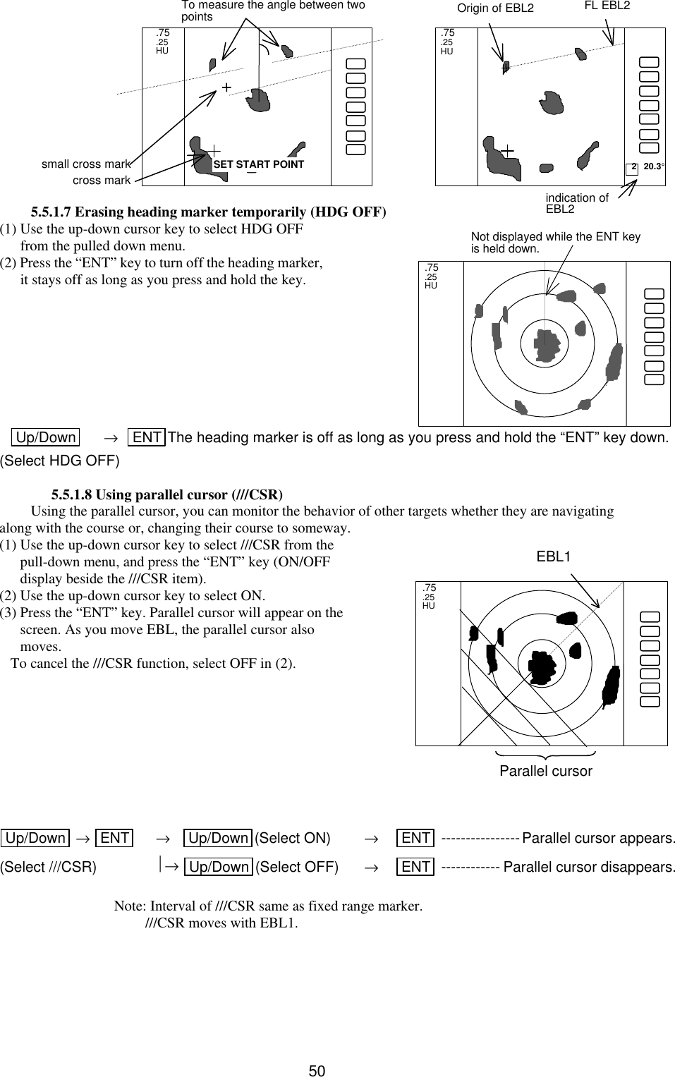
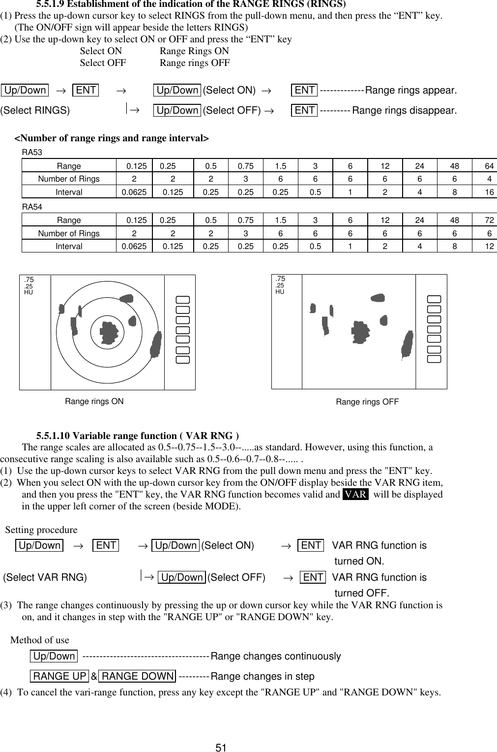
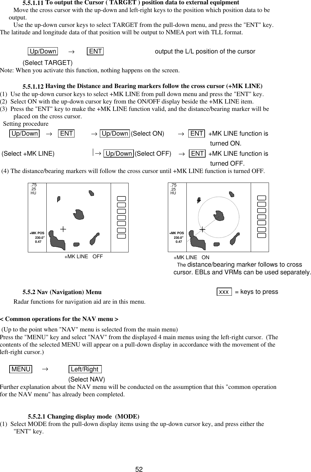
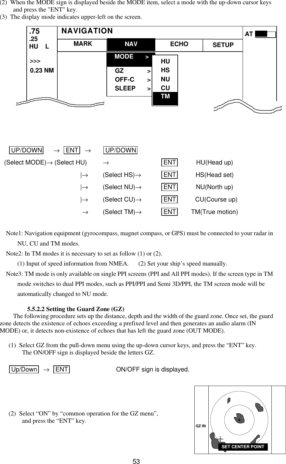
Manual3of4
4.
Manual4of4
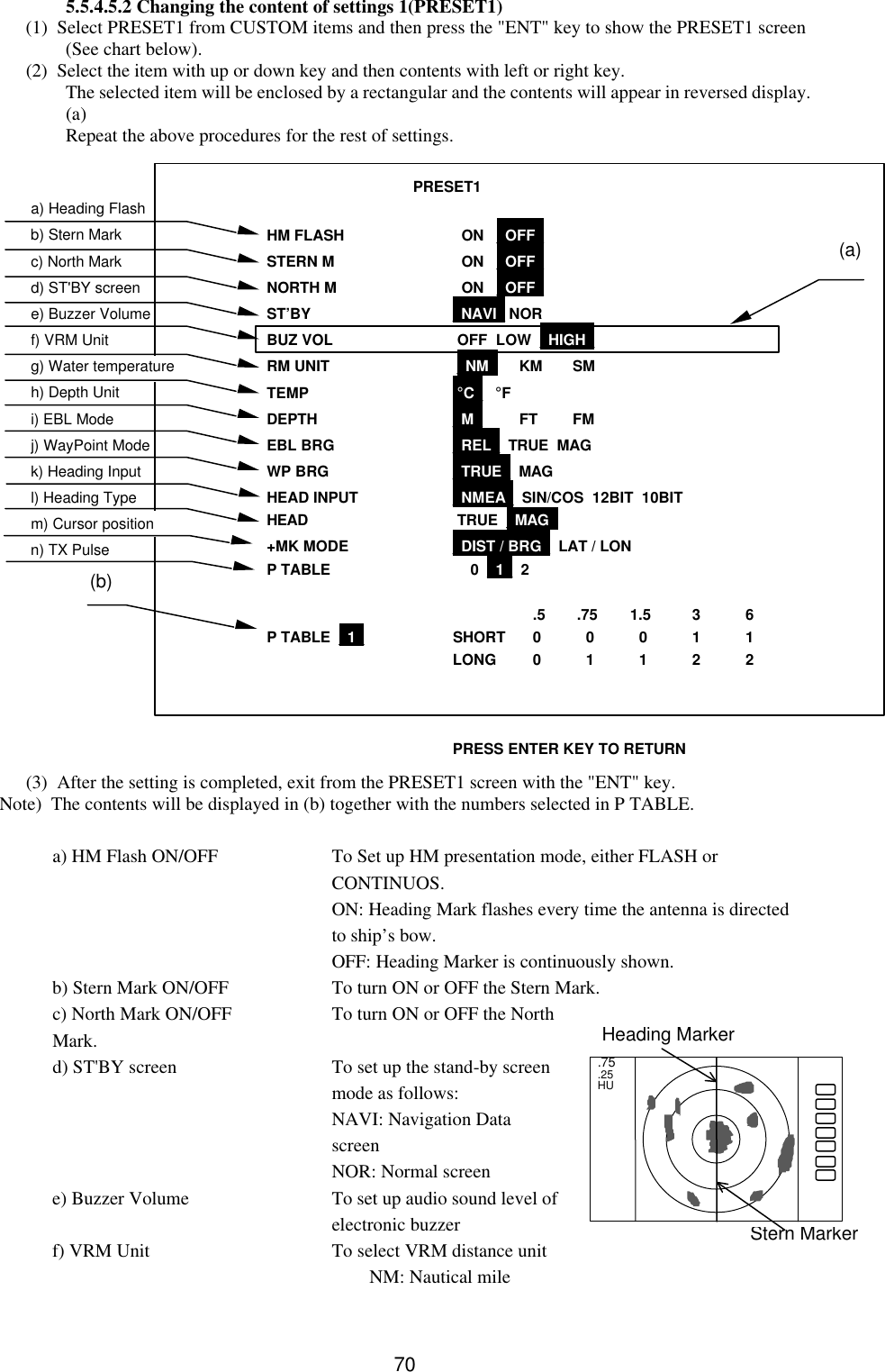
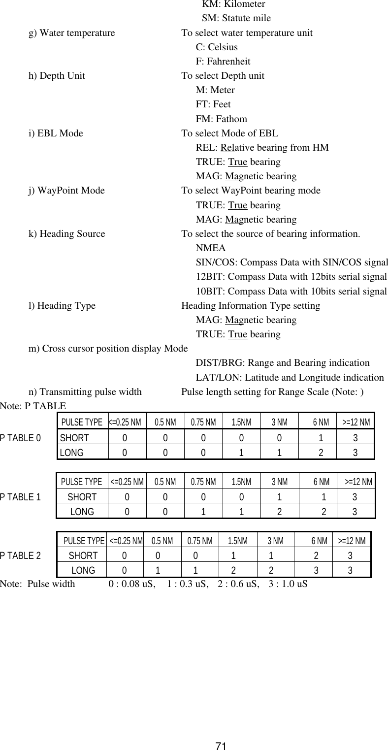
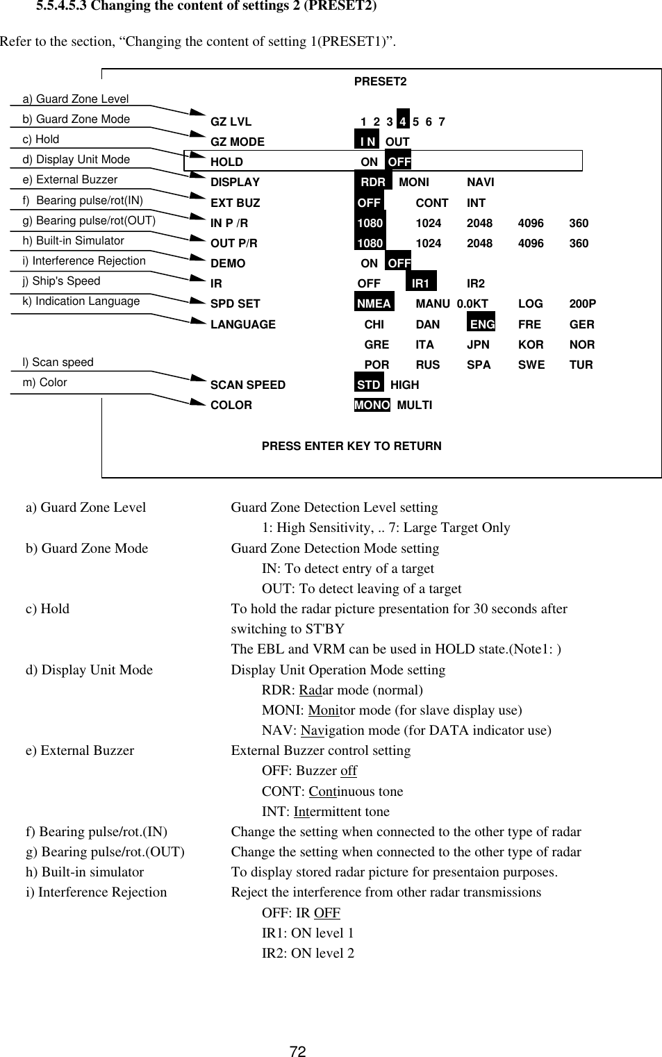
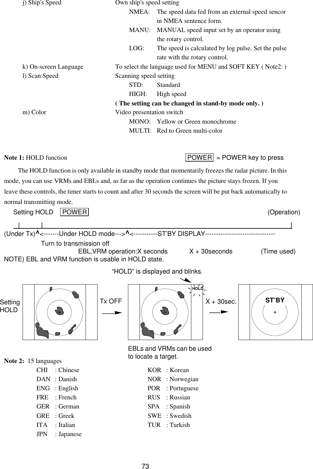
Manual3of4
Navigation menu
Upload a User Manual
Namespaces
Wiki Guide
HTML
PDF
Info
Views
User Manual
Discussion / Help
Navigation