Koden Electronics RB717A Marine Radar RA53 User Manual OME RA5354 4of4
Koden Electronics Co., Ltd Marine Radar RA53 OME RA5354 4of4
Contents
- 1. Manual1of4
- 2. Manula2of4
- 3. Manual3of4
- 4. Manual4of4
Manual4of4
81
CHAPTER 6. MAINTENANCE AND INSPECTION
A qualified engineer should carry out most of maintenance work on this radar. If your radar set has
any problem, contact your local dealer for repair.
Very High Voltage is present inside the radar set. Do
not attempt to open the display rear cover or dis-
assemble internal module. When you open the ra-
dome, make sure to turn off the main power supply
at switch board.
Even if the radar is switched OFF, the radar set is
still powered with very small amount of current.
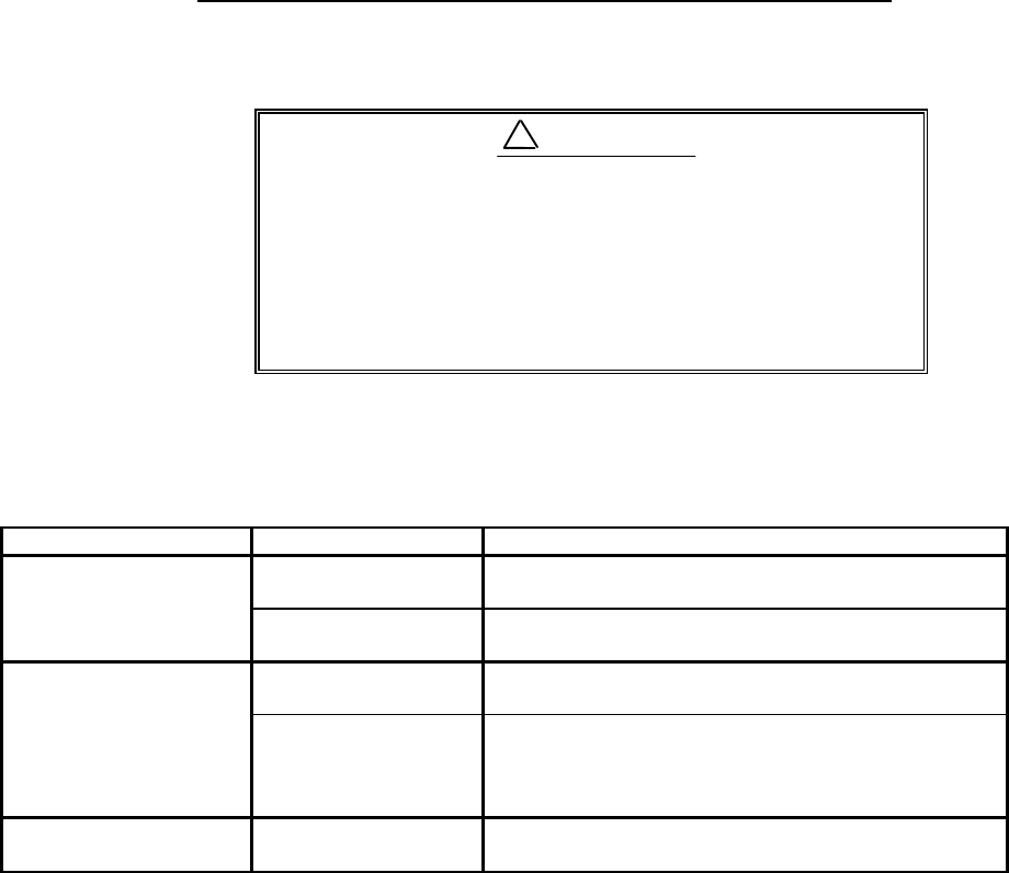
The following table shows the maintenance by user. Please check each item periodically.
Tab. 6-1 Maintenance
Articles of consumption
The radar uses the life-limited parts as listed below that require periodic replacement.
(1) Magnetron This part is used in the scanner unit. If distant echo images have become weak, the
magnetron probably may have degraded. In such a case, you need to replace this item.
Consult your local service agent for replacement.
Practical life to replacement: 3000hour(typ.) (500hour guaranteed by the magnetron
manufacturer)
(2) LCD back-light
This part used in the display unit. If the display screen is extremely dark and its illumi-
nation cannot be corrected by adjusting the screen brightness, the LCD backlighting lamp
may be faulty or may have burnt out. In such a case, you need to replace it. Consult your
local agent for replacement.
Period of the replacement: 15000 hours (typ.) (1000 hours at 0°C)
Inspection Interval Inspection Item Method of Inspection and Maintenance
3-6 months Rust and looseness in
scanner unit Check if the scanner’s fitting bolts are corroded.
Display screen of LCD
display Clean the filter plate and LCD screen surfaces with a soft
and wet cloth. Avoid organic solvent.
6-12 months Grease application to
antenna drive gear Apply an even coating of grease* to the entire surface of
the antenna drive gear with a spatula or brush.
Check for contact of
connectors Check whether connectors are properly connected. If not,
redo connection or make good contact by using a contact
restoring chemical agent or by polishing or replace with a
new one if necessary.
Antenna motor
brush(RA52/53/54) Check the length of brushes. If the length is less than
6mm, replace both brushes with new one.
! WARNING
82
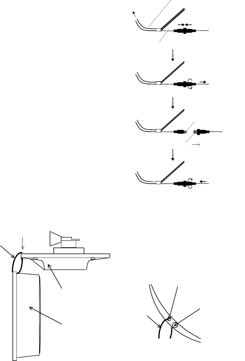
(3) Fuse The fuse is in-line type, built in
to the power supply cable. If the fuse
appears to be blown, check the fuse. If
blown, replace it following the
procedure shown in Fig.6-2.
Fig. 6-2 Method for replacing fuse
Note: Before maintenance of scanner, you can hang a radome (upper) using cord through hole as fol-
lows.
Fig. 6-3 Method for replacing fuse
Fixing screw
Hole
A: Top view
Cord
Cord
A
Radome(Upper)
Radome(bottom)
Push
Power supply cable
Wire(White)
Turn counterclockwise
and pull
Fuse
Spring
Push and turn clockwise
Replace new fuse
To display unit
83
CHAPTER 7. TROUBLESHOOTING
This chapter explains how to identify trouble locations when the radar is found faulty and how to
request repair.
If there is any trouble, press and hold the POWER key for 3 seconds to power off. Then turn on the
equipment again and wait 10 sec at least.
If you find the radar is faulty, check it by the following procedure described below. If you find as
a result of inspection that the fault cannot be repaired on board, contact your distributor for repair.
For faster service, please let us know about followings when you request repair:
(1) Ship’s name, place of anchorage, allowable repair period or time
(2) Radar type (This radar is RA53 or RA54.)
(3) Manufacturing number (indicated on the back of the display unit)
(4) Fault symptoms and inspection results
There are high voltage circuits inside of this radar.
Do not attempt to open the rear cover of display unit
or disassemble internal parts. When you open the
radome for installation, power must be off.
Even if power switch is OFF, this radar is still sup-
plied with power inside.
This chapter explains how to identify trouble locations when the radar is found faulty and how to
request repair.
7.1 Fault Diagnosis by Self-check
The radar incorporates a failure diagnostic function (called "self-check") to diagnose faults by the
equipment itself.
Refer to "5.5.4.4 Fault Diagnosis by Self Check (SYSTEM CHECK)" and check whether there is
any fault in your radar.
! WARNING

84
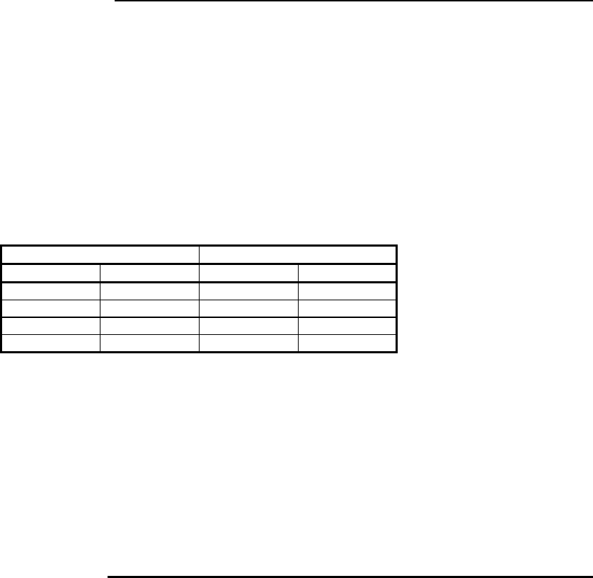
7.2 Inspecting Each Part
When you have finished self-check, inspect each part of the radar according to Tab.7-1.
Tab. 7-1 Troubleshooting
Symptom Cause Corrective action
(1) Radar cannot be powered on.
Power cable is disconnected. Connect power cable correctly.
Power supply voltage is outside
of specified value Use Specified power supply.
(See Section 3.2)
Fuse in power cable is blown. Replace fuse. (See Chapter 6)
(2) Nothing is displayed al-
though radar is powered on. Brightness is improperly ad-
justed. Use BRIL key to adjust. (See
Section 5.3.)
LCD is faulty. Contact your dealer.
(3) Screen is dark. Brightness is improperly ad-
justed. Use BRIL key to adjust. (See
Section 5.3.
Backlight is faulty. Contact your dealer.
(4) Video does not appear al-
though characters are displayed.
Interconnecting cable is out of
place. Connect interconnecting cable
correctly.
(5) Echo image on screen differs
from actual image. Ship’s heading is incorrectly set.
Set ship’s heading correctly.
(See Section 5.5.4.5.4)
Timing adjustment is incorrectly
set. Set timing adjustment correctly.
(See Section 5.5.4.5.4)
(6) Echo images are blurred. GAIN, STC, or FTC is improp-
erly set. Adjust. (See Section 5.3.6 to
5.3.8.)
Magnetron has degraded. Contact your dealer.
(7) Too much noise. Radar is not tuned correctly Adjust TUNE. (See Section
5.5.3.4)
Radar set is not grounded to
earth. Connect grounding wire. (See
Section 3.4 to 3.6.)
(8) No response to key pressing.
Panel keys are not in contact. Contact your dealer.
Power supply circuit is faulty. Contact your dealer.

85
CHAPTER 8. PRODUCT SPECIFICATIONS
8.1 General
Type: RA53 and RA54
Power supply voltage and power consumption
Power supply voltage: 24Vdc (nominal)
(10.2 to 41.6 Vdc)
Power consumption: 100 W or less (RA53)
110 W or less (RA54)
Distance range: 0.125 to 64 NM, 11 ranges
(RA53)
0.125 to 72 NM, 11 ranges
(RA54)
(Continual variable range also
possible)
Distance resolution: Within 25 m
Distance accuracy: Better than 0.9% of maximum
range of the scale in use, or 8m,
whichever is the greater
Minimum detecting distance: Within 25 m
Bearing resolution: Within 2.5° (w/4 ft)
Within 1.8° (w/6 ft)
Bearing accuracy: 1° or less
Warm-up time: 2 minutes
Environment conditions
Ambient temperature range (S/U): -25 to 55 °C
(D/U): 0 to 55 °C
Humidity: 93% RH at +40 °C
Vibration: (S/U): 3 mm( 300 to 500 rpm)
1.2 mm(500 to 1500 rpm)
0.3 mm(1500 to 3000 rpm)
14.7m/s2(1.5G) Resonance test
(D/U): 3 mm(300 to 500 rpm)
0.75 mm(500 to 1500 rpm)
0.2 mm(1500 to 3000 rpm)
Wind resistance: 100 knots (max.)
Waterproof standard: (D/U): IPX-5
(S/U): IPX-6
Interconnecting cable: 100 m in max.
Noise: (D/U): 65 dB or less
(S/U): 70 dB or less
86
8.2 Scanner Unit
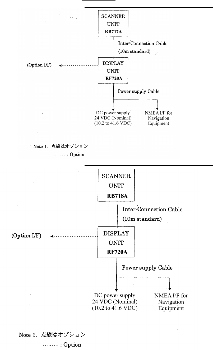
Type: RB717A (RA53)
RB718A (RA54)
Antenna type: Slotted-array
Antenna characteristics
Beam width (horizontal): 1.8° ± 0.2° (with 4ft antenna)
1.2° ± 0.2° (with 6ft antenna)
Beam width (vertical): 22° (typ.)
Pulse width and peak power output:
RA53 RA54
Pulse width (µsec)
Peak Power (kW)
Pulse width (µsec)
Peak Power (kW)
0.08 6 (-50% to +20%)
0.08 12 (-
50% to +20%)
0.3 6 (-50% to +20%)
0.3 12 (-
50% to +20%)
0.6 6 (-50% to +20%)
0.6 12 (-
50% to +20%)
1.0 6 (-50% to +20%)
1.0 12 (-
50% to +20%)
Radio wave type and frequency: P0N, 9410 ± 30 MHz
Antenna revolution: 24 rpm or 48rpm
Transmit/receive switching: Circulator and limiter type
Intermediate frequency: 60 MHz
(logarithmic amplifier)
Noise figure: 6.5 dB or less
8.3 Display Unit
Type: RF720A
Indication system: PPI, PPI+semi-3D,
Split radar range
Indicator: 15-inch color LCD(TFT)
640 x 480 dots
Four(4 ) levels
Cursor Control: Analog cursor key
and rotary encoder
VRM: 2 lines (One line can be offset.)
Unit of distance can be
selected from NM, KM, and
SM.
EBL: 2 lines (One line can be offset.)
Display modes: HU, HS, NU, CU, and TM

87
Off-center: Can be 100% off-centered over
the full range.
Guard zone: Can be set at any desired
distance and angle in any
desired width. IN and OUT
modes are available.
Stretch: 2 modes
Echo track: 15, 30 sec, 1, 3, 6 min. and
continuous.
Other functions: Interference rejection, Zoom,
Sleep mode,
Hold mode, Course error
display,
Parallel cursors, Stern marker,
and Navigation data display
mode
Panel brightness: 4 levels
Language support: Chinese, Danish, English,
French, German, Greek,
Italian, Japanese, Korean,
Norwegian, Portuguese,
Russian, Spanish, Swedish,
and Turkish
8.4 ATA Unit
The ATA Board Specifications
(1) Acquisition Manual
(A target is acquired manually by a cross cursor driven by the Pointing Device.)
(2) Tracking Automatic
(3) Number of tracked targets 10 targets maximum
(4) ATA data output
(Target Number, distance, bearing, speed, course, CPA and TCPA)
(5) Alarm
Collision alarm, activated when a target enters the preset CPA and TCPA ranges.
Lost alarm, activated when a target can no longer be tracked.
(6) Display
Symbols: Predicted point and target number
Vector : Predicted motion of a target as a result of own ship's direction and speed input.
Display modes: Relative (REL)/True (TRUE)
(7) Tracking range 0.5 to 40 NM
(8) PRF 2,000 Hz maximum
(9) Bearing signal 1,080 or 2,048 pulses / rev
(Switched automatically) See
Note.
Note: The ATA board does not accept bearing signals other than specified above. In case the ATA board is
used in the monitor mode display, make sure an incoming bearing pulse rate agrees with that specified in this
specification.

88
8.5 External Interface
NMEA0183: 2 channels
(One standard channel;
Optional cable is required for
2nd-channel connections)
L / L GGA, GLL, RMA, RMC
Heading HDT, HDG, HDM, HSC,
VHW, VTG
Speed VHW, VTG, RMA, RMC
Way point RMB, BEC, BWC,
BWR, BER, BPI
Depth DBT, DPT
Course error RMB, XTE
Seawater temperature MTW
Others (using optional cable):
External buzzer control output, Auxiliary indicator connecting signal
output and input, Bow direction signal input(SIN/COS signals), and
compass interface (10/12 bits serial)
8.6 Standard set
Display unit 1
Scanner unit 1
Display cover 1
Fuse 1 set
Interconnecting cable 1 (10m)
Power supply cable 1 (2m)
M12 hexagonal bolt 4 sets
8.7 Options
Interconnecting cable (15, 20, and 30 m)
Junction box for external connection (with cable 1.5m)
Option connector kit 249J153058
8.8 External dimensions and weight
See APPENDIX

89
8.9 External Connection and function
X1 Connector for Option
pin No. Name function
1 NMEA2-A NMEA ch2 data input(A)
19 NMEA2-B NMEA ch2 data input(B)
2 GND
20 EXBUZ+ Output for External Buzzer
3 EXBUZ- Output for External Buzzer
controlled ship's power output
21 VIDEO_IN Video input for Monitor operation
0 to -1V negative video, Zi = 50ohm
4 VIDEO_OUT Video output for External Monitor
0 to -1V negative video, Zo = 50ohm
22 GND
5 TRIG_IN Trigger signal input for Monitor operation
0 to 5V positive pulse, rising edge
23 TRIG_OUT Trigger output for External Monitor
0 to 5V positive pulse, rising edge
6 SHF_IN Heading signal input for Monitor operation
0 to 5V negative pulse, falling edge
24 SHF_OUT Heading signal output for External Monitor
0 to 5V negative pulse, falling edge
7 AZI_IN Bearing Pulse input for Monitor operation
0 to 5V positive pulse, rising edge
25 AZI_OUT Bearing Pulse output for External Monitor
0 to 5V positive pulse, rising edge
8 GND
26 GYRCK+ Gyro Interface clock(+) input
9 GYRCK- Gyro Interface clock(-) input
apply 5V pulse between (+) and (-), isolated
27 GYRDT+ Gyro Interface data(+) input
10 GYRDT- Gyro Interface data(-) input
apply 5V pulse between (+) and (-), isolated
28 GND
11 MARK_I External Marker signal input, ex) Radar Buoy
negative video, 0 to -1V Zi = 50ohm
29 +12V External interface power, 100mA max.
12 SIN Compass Interface for SIN/COS type
30 COS Compass Interface for SIN/COS type
13 REF Compass Interface for SIN/COS type
SIN/COS signal: SIN = REF+/-1V, COS = REF+/-1V
31 -- not used
14 GND
32 NMEA_OUT NMEA data output, ex) MOB data, TARGET data
90
Appendix
1. RA53 General System Diagram
2. RA54 General System Diagram
91
3. Interconnection Diagram
E41-100 PCB (J2): RA53
E41-101 PCB (J2): RA54
No.
Color Function
1
17 VIOLET +250 V
2
NC
3
17 YELLOW GND
4
34 RED SHIP’S+
5
34 YELLOW SHIP’S+
6
34 GREEN SHIP’S-
7
34 BLUE SHIP’S-
E41-100 PCB (J1): RA53
E41-101 PCB (J1): RA54
No.
Color Function
1
17 BLUE +24V
2
NC
3
34 ORANGE +12V
4
Braid of RED DAT-R
5
RED DAT
6
Braid of BROWN BP/SHF-R
7
BROWN BP/HG
8
Braid of GRAY V/TRG-R
9
GRAY V/TRG
POWER PCB (J1)
No.
Color Function
1
17 VIOLET +250 V
2
17 BLUE +24V
3
34 ORANGE +12V
4
17 YELLOW GND
5
Braid of RED DAT-R
6
RED DAT
7
NC
8
BROWN BP/SHF
9
Braid of BROWN BP/SHF-R
10
GRAY V/TRG
11
NC
12
34 RED SHIP’S+
13
34 YELLOW SHIP’S+
14
Braid of GRAY V/TRG-R
15
34 GREEN SHIP’S-
16
34 BLUE SHIP’S-
DISPLAY
UNIT
SCANNER
UNIT
92
A
Adjustment
Distance.......................................75
Angle ...........................................76
Tuning.........................................77
Antenna height...........................78
Automatic gain............................78
Automatic STC............................79
ALL PPI Screen.....................................65
ALL PPI/PPI Screen..............................65
ATA
Acquisition ..................................81
All cancel.....................................82
ATA..............................................80
ATA alarm...................................80
ATA Data display .......................82
ATA Data output ........................83
ATA setting.................................81
ATA symbol.................................83
Cancel tracking...........................82
CPA..............................................80
Log signal....................................84
Ship’s speed.................................83
TCPA...........................................80
Tracking ......................................81
B
Bearing ..................................................26
Brilliance................................................28
Buzzer volume.......................................71
C
Changing the setting (CUSTOM).........68
Course error (XTE)................................27
Cross cursor (+)......................................26
D
Display modes (MODE).........................37,52
E
EBL .....................................................34,46
Echo expansion (ST) .............................40,57
Echo Menu.............................................56
F
False echoes...........................................4
FL VRM2, FL EBL2 ..............................35,47
FTC .....................................................32,57
G
Gain .....................................................31,56
Guard zone (GZ) ....................................38,53
Guard zone mode (GZ MODE) ...73
Guard zone level (GZ LVL).........73
H
Heading marker.....................................6
Heading Off (HDG OFF).............37,49
Heading flash (HM FLSH).........71
Heading angle (HDG).................25
Hold (HOLD)..........................................73
L
Language ...............................................73
M
+MK LINE.............................................51
Menu .....................................................45
Man Over Board (MOB)........................33
MOB Screen...........................................65
Monitor mode (MONI)...........................73
N
Nav (Navigation) Menu.........................52
Navigation screen..................................27
North mark (NORTH M).......................6,71
O
Off-center (OFF-C) ................................38,54
Option ....................................................93
P
Parallel cursor (///CSR) .........................37,49
PPI Screen .............................................63
PPI/NAV Screen ....................................65
PPI/PPI Screen......................................63
PPI/SEMI3D Screen..............................63
P TABLE (Pulse table)..........................72
R
Radar interference.................................6
Radar screen..........................................25, 26,27
Range .....................................................30
Range rings (RINGS).............................37,50
Range ring interval.....................50
Reverse display......................................66
S
Semi-3D .................................................42,63
Sleep (SLEEP) .......................................54
Speed (SPD SET)...................................74
ST'BY .....................................................29
ST'BY screen..........................................71
STC .....................................................32,57
Stern mark (STERN M) ........................71
Switching the screen (SEL WIN)..........41,64
Self check (SYSTEM CHECK)..............67
93
T
Target (TARGET) ................................. 51
Track (TRACK) ..................................... 40,58
Tune .................................................... 40,57
Tune meter ........................................... 26
V
VAR RNG.............................................. 37,50
VRM1..................................................... 34,47
VRM unit (VRM UNIT)........................ 71
W
Way point (WP)..................................... 27
WP BRG (Bearing of Way point).......... 71
X
XTE (Course error) ............................... 25,27
Z
ZOOM.................................................... 40,59