Koden Electronics RB808P X BAND MARINE RADAR User Manual MDC 7000P 7900P OME Rev05E
Koden Electronics Co., Ltd X BAND MARINE RADAR MDC 7000P 7900P OME Rev05E
Contents
- 1. User Manual MDC 5200 5500
- 2. User Manual MDC 7000p 7900p
User Manual MDC 7000p 7900p


MDC-7000P/7900P Series Revision History
0093169006-05E i
MDC-7000P/7900P Series Operation Manual
Doc No: 0093169006
Document Revision History
No. Doc. No.- Rev. No. Date Revised
(Y/M/D)
Revised Content
0 0093169006-05 2015/08/30 First edition
1 0093169006-05A 2016/03/09 Wording
2 0093169006-05B 2016/04/08 Chapter 2 EXPANSION, Wording
3 0093169006-05C 2016/05/20 Revised document code of cover, Chapter 2,
Chapter 9
4 0093169006-05D 2016/12/12 DATUM [TOY] and SEA OFFSET addition,
Correction
5 0093169006-05E 2016/12/22 For Your Safe Operation FCC/IC addition,
Chapter 6 C-MAP chart display addition
6
7
8
9
10
Document No. Revised Version Norm
When part of the document needs to be revised, the document has advanced revision number.
The document No. is indicated at the lower right side on the cover and at the left or right side of the
footer region of each page.
© 2015-2016 Koden Electronics Co., Ltd. All rights reserved.
No part of this publication may be reproduced, transmitted, translated in any from by any means without
the written permission of Koden Electronics Co., Ltd. The technical descriptions contained in this
publication are subject to change without notice. Koden assumes no responsibility for any errors,
incidentals or consequential damages caused by misinterpretation of the descriptions contained in this
publication.

Important Notice MDC-7000P/7900P Series
ii 0093169006-05E
Important Notice
For copy and transcription of this Operation Manual (hereinafter referred to as this manual),
permission from Koden is needed. Koden prohibits the un-authorized copy and transcription of this
manual.
If this manual is lost or damaged, consult a dealer of Koden or Koden.
The specification of the products and the contents in this manual are subject to change without
notice.
The contents displayed on the menu of product may be different from the expression of this
manual. The fonts and shapes of the keys and menus in the illustration may differ from the actual
ones, and some parts may be omitted.
Koden is not liable for damages and troubles arisen from misunderstanding of the contents in this
manual.
Koden is not liable for any damages caused by earthquake, lightning, wind and flood damage and
fire for which Koden is not responsible, and actions by third parties, other accidents, customer’s
unintended error/abuse and the use under other abnormal conditions.
Koden is not liable for damages of accompaniment (change/loss of memorized content, loss of
business profit, stop of business) arisen from use or failure of our products.
If the stored data are changed or lost, irrespective of causes of troubles and damages, Koden is
not liable for them.
Koden is not liable for any damages arisen from malfunction caused by combination of software
and connected equipment in which Koden is not engaged.
MDC-7000P/7900P Series For Your Safe Operation
0093169006-05E iii
For Your Safe Operation
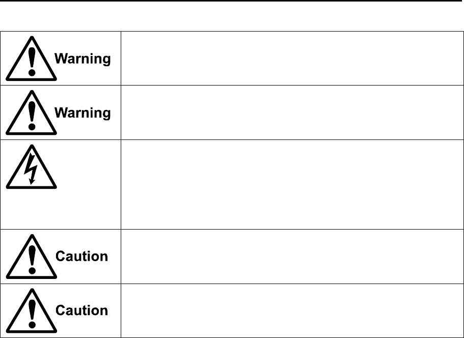
Symbols used in this Operation Manual
This manual uses the following symbols. Understand the meaning of each symbol and implement the
maintenance and inspection.
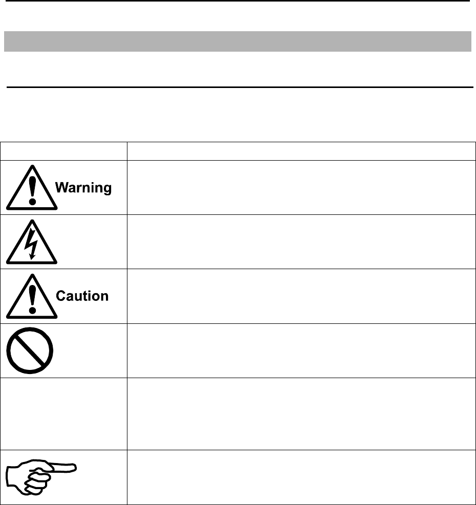
Symbol Meaning
Warning Symbol
This symbol denotes that there is a risk of death or serious injury when not
dealt with it correctly.
High Voltage Danger Symbol
This symbol denotes that there is a risk of death or serious injury caused
by electric shock when not dealt with it correctly.
Caution Symbol
This symbol denotes that there is a risk of slight injury or damage of device
when not dealt with it correctly.
Prohibition Symbol
This symbol denotes restriction of the specified conduct. Description of the
restriction is displayed near the mark.
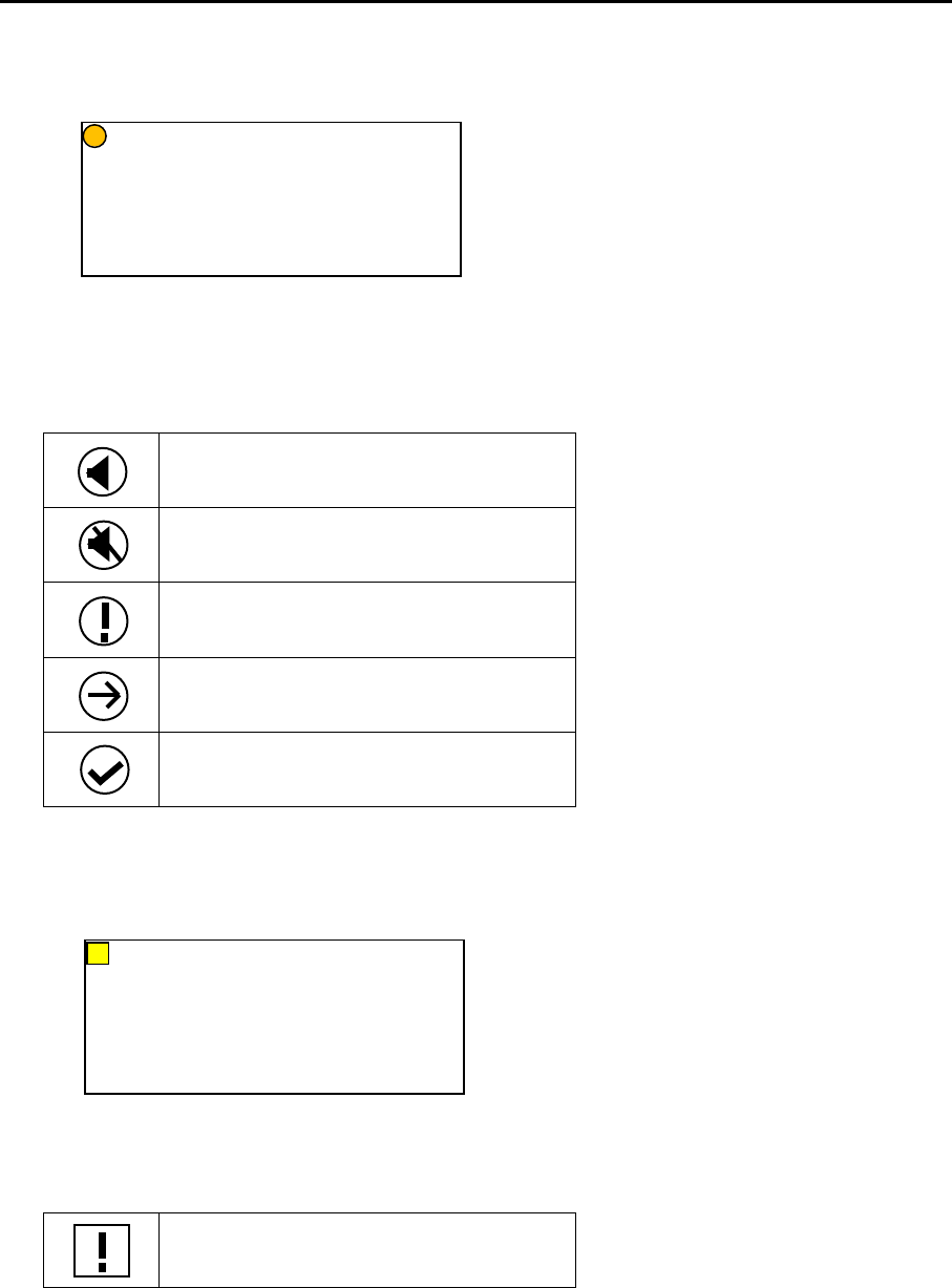
IMPORTANT
Important Symbol
This mark indicates important area where attention is needed. This may
include possible data lose or other issues that may interfere with radar
operation.
Reference Symbol
This mark shows the part to be referred to concerning this description.
For Your Safe Operation MDC-7000P/7900P Series
iv 0093169006-05E
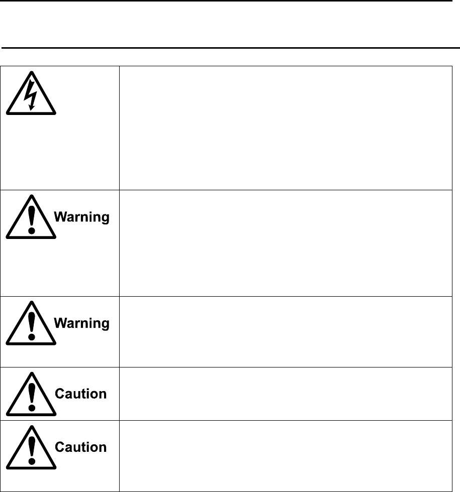
Caution related to Equipment
Caution, high voltage inside.
High voltage that may cause severe injury or death is present. High
voltage remains in circuit even after power is turned off. High voltage
circuit has a protective cover with a warning label. Make sure to turn off
power and discharge capacitors before working on the system. Only
authorized personnel should access this circuit for repair and
maintenance.
Confirm main power is turned off before servicing the
equipment.
If power switch is turned on while working on the system, possible
severe injury or death may occur due to high voltage. Make sure main
power is off and a label “Work In Progress” is attached to the breaker
powering the system.
Caution related to dust
Inhaling dust may cause A respiratory disease. When cleaning the inside
of equipment, be careful not to inhale dust. Wearing a safety mask is
recommended.
When choosing equipment location
Do not install the equipment where it is excessively damp, humid and
under direct dripping water.
Caution related to static electricity
Static electricity may be generated from floor carpet or synthetic clothes.
Static may destroy some electronics parts of the circuit and therefore
anti-static measures should be done.
MDC-7000P/7900P Series For Your Safe Operation
0093169006-05E v
Caution rellated to Handling
ENGLISH
Caution related to rotating aerial
The radar antenna may start rotating to rotate without notice. Please stand
clear from the antenna for your safety.
Caution related to electromagnetic disturbance
The operating Antenna & Scanner unit radiates high-energy
electromagnetic wave. It may cause harmful effect for human body due to
its continuous radiation. As International regulation says, electromagnetic
waves less than 100 watt/m2 does not have a harmful effect on human
bodies, but some kind of medical devices such as heart pacemakers are
sensitive even under the low energy electromagnetic wave. Any personnel
with such a device should keep away from the electromagnetic wave
generating position at all times.
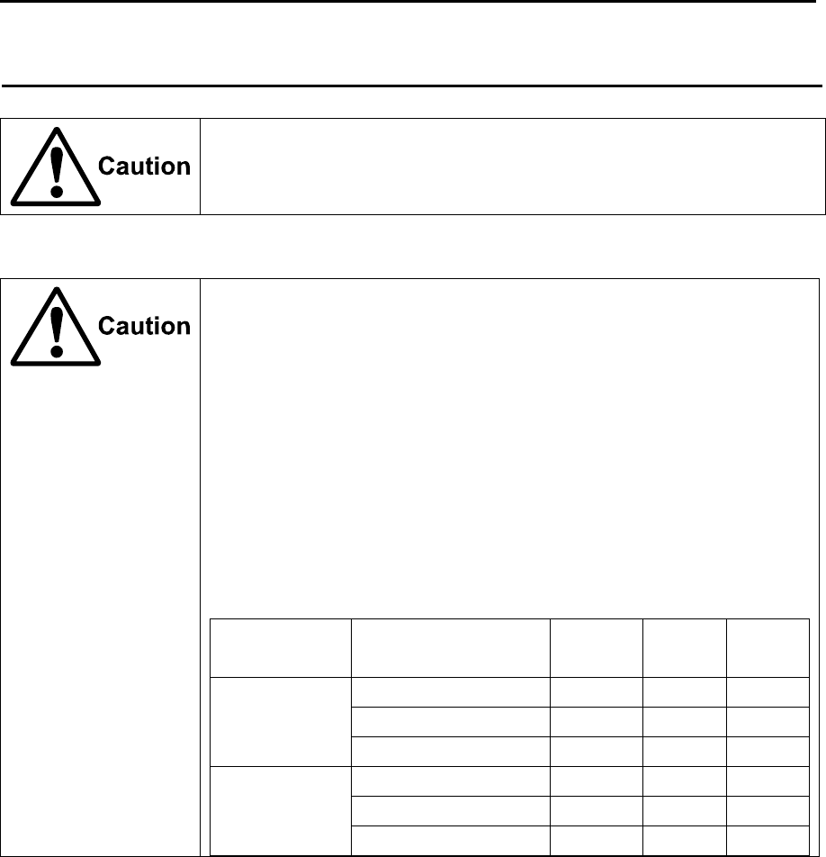
Specified power density and distance from the radar (in accordance with the
provision as specified in IEC 60945)
Model name Transmission power /
Antenna length
100W/m2 50W/m2 10W/m2
MDC-7012P
MDC-7912P
12kW / 4 feet Antenna 2.01m 2.84m 6.34m
12kW / 6 feet Antenna 2.38m 3.37m 7.54m
12kW / 9 feet Antenna 2.83m 4.01m 8.96m
MDC-7025P
MDC-7925P
25kW / 4 feet Antenna 2.89m 4.09m 9.15m
25kW / 6 feet Antenna 3.44m 4.86m 10.88m
25kW / 9 feet Antenna 4.09m 5.78m 12.93m
For Your Safe Operation MDC-7000P/7900P Series
vi 0093169006-05E
FRENCH:
Mise en garde relative aux perturbations électromagnétiques produites
par les radars de navire
L'antenne & l’émetteur des radars de navire ont un rayonnement d’ondes
électromagnétique de haute intensité. Ceci peut causer des effets nocifs pour le
corps humain en raison de son rayonnement continu. Comme la réglementation
internationale le spécifie, les ondes électromagnétiques à moins de 100 watt/m2
n'ont pas un effet néfaste sur le corps humain, mais certains types d’appareils
médicaux tels que les stimulateurs cardiaques peuvent être affectes même par des
ondes électromagnétiques de faible énergie. Tout membre du personnel avec un tel
dispositif devrait se tenir à l'écart des générateurs d'ondes électromagnétiques en
tout temps.
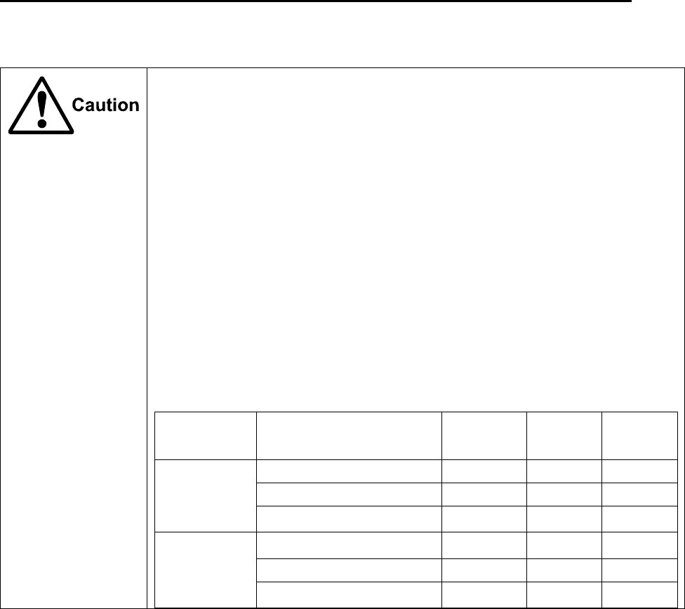
Spécification de densité de la puissance et de la distance du radar (conformément à
la disposition comme spécifié dans la IEC 60945)
Nom Modèle Puissance de transmission
/ longueur d’antenne
100W/m2 50W/m2 10W/m2
MDC-7012P
MDC-7912P
12kW / Antenne 4 pieds 2.01m 2.84m 6.34m
12kW / Antenne 6 pieds 2.38m 3.37m 7.54m
12kW / Antenne 9 pieds 2.83m 4.01m 8.96m
MDC-7025P
MDC-7925P
25kW / Antenne 4 pieds 2.89m 4.09m 9.15m
25kW / Antenne 6 pieds 3.44m 4.86m 10.88m
25kW / Antenne 9 pieds 4.09m 5.78m 12.93m

MDC-7000P/7900P Series For Your Safe Operation
0093169006-05E vii
Warning Statements related to FCC and IC rules
IC RSS-GEN, Sec 8.3 Warning Statement- (Required for Transmitters
w/ detachable antennas)
ENGLISH:
This radio transmitter (identify the device by certification number, or model number if
Category II) has been approved by Industry Canada to operate with the antenna types
listed below with the maximum permissible gain and required antenna impedance for
each antenna type indicated. Antenna types not included in this list, having a gain greater
than the maximum gain indicated for that type, are strictly prohibited for use with this
device.
FRENCH:
Le présent émetteur radio (identifier le dispositif par son numéro de certification ou son
numéro de modèle s'il fait partie du matériel de catégorie I) a été approuvé par Industrie
Canada pour fonctionner avec les types d'antenne énumérés ci-dessous et ayant un gain
admissible maximal et l'impédance requise pour chaque type d'antenne. Les types
d'antenne non inclus dans cette liste, ou dont le gain est supérieur au gain maximal
indiqué, sont strictement interdits pour l'exploitation de l'émetteur.
Antenna type name Antenna Gain (dBi) Required Impedance (ohm)
RW701A-04 27.0dBi 50ohm
RW701A-06 28.5dBi 50ohm
RW701B-09 30.0dBi 50ohm

For Your Safe Operation MDC-7000P/7900P Series
viii 0093169006-05E
IC RSS-102, Sec 2.6 Warning Statement Requirements
ENGLISH:
The applicant is responsible for providing proper instructions to the user of the radio
device, and any usage restrictions, including limits of exposure durations. The user
manual shall provide installation and operation instructions, as well as any special usage
conditions, to ensure compliance with SAR and/or RF field strength limits. For instance,
compliance distance shall be clearly stated in the user manual.
FRENCH:
Le demandeur est responsable de fournir des instructions appropriées et toute restriction
d'utilisation, y compris les limites des durées d'exposition, à l'utilisateur de l'appareil radio.
Le manuel de l'utilisateur doit fournir des instructions d'installation et d'utilisation, ainsi
que toutes les conditions d'utilisation spéciales, pour assurer la conformité aux limites
SAR et / ou RF. Par exemple, la distance de conformité doit être clairement indiquée
dans le manuel de l'utilisateur.
IC RSS-GEN, Sec 8.4 Warning Statement- (Required for
license-exempt devices)
ENGLISH:
This device complies with Industry Canada license-exempt RSS standard(s). Operation is
subject to the following two conditions: (1) this device may not cause interference, and (2)
this device must accept any interference, including interference that may cause undesired
operation of the device.
FRENCH:
Le présent appareil est conforme aux CNR d'Industrie Canada applicables aux appareils
radio exempts de licence. L'exploitation est autorisée aux deux conditions suivantes : (1)
l'appareil ne doit pas produire de brouillage, et (2) l'utilisateur de l'appareil doit accepter
tout brouillage radioélectrique subi, même si le brouillage est susceptible d'en
compromettre le fonctionnement.

MDC-7000P/7900P Series For Your Safe Operation
0093169006-05E ix
Warning statement regarding RF exposure compliance
ENGLISH:
The user manual of devices intended for controlled use shall also include information
relating to the operating characteristics of the device; the operating instructions to ensure
compliance with SAR and/or RF field strength limits; information on the installation and
operation of accessories to ensure compliance with SAR and/or RF field strength limits;
and contact information where the user can obtain Canadian information on RF exposure
and compliance. Other related information may also be included.
FRENCH:
Le manuel de l'utilisateur des dispositifs destinés à une utilisation contrôlée doit
également comporter des informations relatives aux caractéristiques de fonctionnement
du dispositif; Le mode d'emploi pour assurer la conformité aux limites SAR et / ou RF; Des
informations sur l'installation et le fonctionnement des accessoires afin d'assurer la
conformité aux limites SAR et / ou RF; Et des coordonnées où l'utilisateur peut obtenir des
renseignements canadiens sur l'exposition aux radiofréquences et la conformité. D'autres
renseignements connexes peuvent également être inclus.
FCC Part 15.19 Warning Statement
THIS DEVICE COMPLIES WITH PART 15 OF THE FCC RULES. OPERATION IS
SUBJECT TO THE FOLLOWING TWO CONDITIONS: (1) THIS DEVICE MAY NOT
CAUSE HARMFUL INTERFERENCE, AND (2) THIS DEVICE MUST ACCEPT ANY
INTERFERENCE RECEIVED, INCLUDING INTERFERENCE THAT MAY CAUSE
UNDESIRED OPERATION.
FCC Part 15.21 Warning Statement
NOTE: THE GRANTEE IS NOT RESPONSIBLE FOR ANY CHANGES OR
MODIFICATIONS NOT EXPRESSLY APPROVED BY THE PARTY RESPONSIBLE FOR
COMPLIANCE. SUCH MODIFICATIONS COULD VOID THE USER’S AUTHORITY TO
OPERATE THE EQUIPMENT.
FCC Part 15.105(b) Warning Statement
NOTE: This equipment has been tested and found to comply with the limits for a Class B
digital device, pursuant to part 15 of the FCC Rules. These limits are designed to provide
reasonable protection against harmful interference in a residential installation. This
equipment generates uses and can radiate radio frequency energy and, if not installed
and used in accordance with the instructions, may cause harmful interference to radio
communications. However, there is no guarantee that interference will not occur in a

For Your Safe Operation MDC-7000P/7900P Series
x 0093169006-05E
particular installation. If this equipment does cause harmful interference to radio or
television reception, which can be determined by turning the equipment off and on, the
user is encouraged to try to correct the interference by one or more of the following
measures:
- Reorient or relocate the receiving antenna.
- Increase the separation between the equipment and receiver.
-Connect the equipment into an outlet on a circuit different from that to which the receiver
is connected.
-Consult the dealer or an experienced radio/TV technician for help.
MDC-7000P/7900P Series For Your Safe Operation
0093169006-05E xi
Do not disassemble or modify. It may lead to trouble, fire, smoking or
electric shock. In case of trouble, contact our dealer or our company.
In case of smoke or fire, switch off the power in the boat and the power of
equipment. It may cause fire, electric shock or damage.
Caution related to remaining high voltage.
A high voltage may remain in the capacitor for several minutes after
system is powered off. Before inspecting inside, wait at least 5 minutes
after powering off or discharging the remaining electricity in an appropriate
manner. Then, start the work.
The information displayed in this unit is not provided directly for your
navigation. For your navigation, be sure to see the specified material.
Use properly rated fuse. If incorrect fuse is used, it may cause fire, smoke
or damage.

For Your Safe Operation MDC-7000P/7900P Series
xii 0093169006-05E
Break in procedure of stored radar
Following procedure is recommended for “Break In” of the stored radar.
Otherwise the radar sometimes exhibits unstable transmitting operation
such as arcing at its initial operation after long period of storage and make
the operation more difficult.
1. Extend preheat time as long as possible (preferably 20 to 30
minutes).
2. Set the pulse width to the shortest one and start the operation.
When the operation in the shortest pulse is stable then go to
operation in longer pulse and repeat the similar step until the
operation reaches to the final pulse condition.
MDC-7000P/7900P Series Disposal of used cell and this radar
0093169006-05E xiii
Used battery and radar disposal
Treatment of the used lithium ion battery
To dispose of built-in lithium ion battery (CR2032) in this radar, insulate each terminal with tape, and
wrap in plastic bag.
The disposal and collection rules may be different depending on each municipal district. Obey the
directions of each district.
Disposal of this radar
This radar shall be disposed according to the municipal regulations or rules.
A high-energy density lithium ion battery is installed in this radar.
Improper disposal of a lithium ion battery is discouraged as the battery
has a possibility of short-circuiting. If it gets wet, the generation of heat,
explosion or ignition may occur resulting in an injury or fire.

Contents MDC-7000P/7900P Series
xiv 0093169006-05E
Contents
Document Revision History ........................................................................................................ i
Important Notice ........................................................................................................................ ii
For Your Safe Operation .......................................................................................................... iii
Break in procedure of stored radar ......................................................................................... xii
Used battery and radar disposal ............................................................................................ xiii
Contents ................................................................................................................................ xiv
Introduction ............................................................................................................................. xxi
Configuration items ............................................................................................................... xxii
System configuration ................................................................................................ xxii
Option ...................................................................................................................... xxiii
Chapter 1 Display and Operation ............................................................................. 1-1
1.1 Radar Display ............................................................................................................ 1-1
Upper left corner ....................................................................................................... 1-1
Lower left corner ....................................................................................................... 1-2
Lower right corner..................................................................................................... 1-2
Own ship data ........................................................................................................... 1-3
Target status ............................................................................................................. 1-3
Target and MAP information area ............................................................................. 1-4
Assistant display (Navigation information) ............................................................... 1-5
Alarm display area .................................................................................................... 1-6
1.2 Operation Unit ........................................................................................................... 1-8
1.3 Menu usage ............................................................................................................. 1-10
Turn MENU on and off ............................................................................................ 1-10
Select menu item .................................................................................................... 1-10
Display [MAINTENANCE] menu ............................................................................ 1-11
1.4 Cursor Access usage .............................................................................................. 1-11
Chapter 2 Radar Basic Operation ............................................................................ 2-1
2.1 Power ON/OFF .......................................................................................................... 2-1
Power ON ................................................................................................................. 2-1
Power OFF ............................................................................................................... 2-1
2.2 Change Brilliance ...................................................................................................... 2-2
Display Brilliance ...................................................................................................... 2-2
Operation unit Brilliance ........................................................................................... 2-2
2.3 Transmission ............................................................................................................. 2-3
Transmission ON ...................................................................................................... 2-3
Transmission OFF .................................................................................................... 2-3

MDC-7000P/7900P Series Contents
0093169006-05E xv
2.4 Tuning method .......................................................................................................... 2-4
Change MAN (manual) and AUTO........................................................................... 2-4
Optimized value setup method ................................................................................ 2-4
2.5 Change range scale .................................................................................................. 2-5
Change range unit (NM / km) ................................................................................... 2-5
2.6 Adjust receiver gain (GAIN) ...................................................................................... 2-6
Selection of MAN GAIN and AUTO GAIN ................................................................ 2-6
AUTO adjustment of GAIN ....................................................................................... 2-6
MAN adjustment of GAIN ......................................................................................... 2-7
2.7 Reject sea clutter (anti-SEA)..................................................................................... 2-8
Selection of MAN SEA and AUTO SEA ................................................................... 2-8
AUTO adjustment of SEA ........................................................................................ 2-9
Manual adjustment of SEA ....................................................................................... 2-9
2.8 Reject rain/snow clutter (anti-RAIN) ....................................................................... 2-10
Changing method of CFAR and MAN .....................................................................2-11
CFAR (Constant False Alarm Rate) adjustment .....................................................2-11
RAIN MAN (manual) adjustment ............................................................................ 2-12
2.9 Change transmission pulse width (SP/LP) ............................................................. 2-13
2.10 Select Display Mode ............................................................................................... 2-14
For H UP (Head up mode) ..................................................................................... 2-14
For C UP (Course up mode) .................................................................................. 2-15
For N UP (North up mode) ..................................................................................... 2-16
For relative motion (RM) and true motion (TM)...................................................... 2-17
Reset true motion ................................................................................................... 2-18
2.11 Ground and Sea stabilization .................................................................................. 2-19
SEA (Sea stabilization) ........................................................................................... 2-19
GND (Ground stabilization) .................................................................................... 2-20
2.12 Measurement of distance by RR and VRM ............................................................ 2-21
Display Range Rings (RR) ..................................................................................... 2-21
Measurement Range (VRM: Variable Range Marker) ........................................... 2-22
Measurement Range (Cursor) ............................................................................... 2-22
2.13 Measurement of bearing by EBL ............................................................................ 2-23
Using the EBL OFFSET ......................................................................................... 2-24
2.14 Bearing mode set up ............................................................................................... 2-25
2.15 Measurement of distance/bearing by PI ................................................................. 2-26
2.16 Measurement distance/bearing by ERBL ............................................................... 2-28
Change ERBL mark to LINE or RING .................................................................... 2-29
Change ERBL offset method.................................................................................. 2-29
2.17 Change color and brightness (Day/Night) ............................................................... 2-30

Contents MDC-7000P/7900P Series
xvi 0093169006-05E
Setup color ............................................................................................................. 2-30
Setup brightness ..................................................................................................... 2-30
Color and brightness settings reset ........................................................................ 2-30
2.18 Remove the heading line/navigation data ............................................................... 2-31
2.19 Target trail ................................................................................................................ 2-31
Relative display (R) ................................................................................................ 2-33
True display (T) ...................................................................................................... 2-33
2.20 Off Center ................................................................................................................ 2-34
2.21 Function key usage ................................................................................................. 2-35
2.22 Set picture mode ..................................................................................................... 2-36
2.23 Echo process ........................................................................................................... 2-37
Correlation image echo process ............................................................................. 2-37
2.24 Echo expansion ....................................................................................................... 2-38
2.25 Interference rejection (IR) ....................................................................................... 2-39
2.26 Video contrast ......................................................................................................... 2-39
2.27 Noise rejection ......................................................................................................... 2-40
2.28 Echo color rejection ................................................................................................. 2-40
2.29 Pulse width .............................................................................................................. 2-41
2.30 Receiving Radar Beacons, SART and Radar Enhancer ......................................... 2-42
2.31 Inter-switch .............................................................................................................. 2-44
2.32 Cursor data .............................................................................................................. 2-46
CURSOR setting menu .......................................................................................... 2-46
2.33 Performance monitor ............................................................................................... 2-47
2.34 Reference position and Display center ................................................................... 2-48
Reference position ................................................................................................. 2-48
Display center ......................................................................................................... 2-48
Antenna position mark ON or OFF ......................................................................... 2-49
2.35 Setup own ship outline ............................................................................................ 2-50
Setup CCRP number and ship outline ................................................................... 2-50
2.36 FERRY MODE ........................................................................................................ 2-51
Chapter 3 Alarm ....................................................................................................... 3-1
Collision avoidance .................................................................................................. 3-1
3.1 Echo alarm ................................................................................................................ 3-1
How to set echo alarm area (Fan type) .................................................................... 3-1
3.2 Map area alarm ......................................................................................................... 3-3
How to edit map area ............................................................................................... 3-3
How to move map area ............................................................................................ 3-4
How to add data to map area ................................................................................... 3-5

MDC-7000P/7900P Series Contents
0093169006-05E xvii
How to delete the data of map area ......................................................................... 3-6
How to clear entire block of map area data ............................................................. 3-6
3.3 Guard zone alarm ..................................................................................................... 3-7
How to set guard zone alarm ................................................................................... 3-7
3.4 Nav line cross ........................................................................................................... 3-8
How to edit ............................................................................................................... 3-8
How to move nav line ............................................................................................... 3-9
How to add ............................................................................................................. 3-10
How to delete ..........................................................................................................3-11
How to clear ............................................................................................................3-11
3.5 Alarm List ................................................................................................................ 3-12
3.6 Alarm History list ..................................................................................................... 3-13
3.7 Alarm on/off (TT and AIS) ....................................................................................... 3-14
Chapter 4 Target (AIS, TT and Trial manoeuvre) ......................................................4-1
4.1 Common setting ........................................................................................................ 4-1
VECTOR REL/TRUE ............................................................................................... 4-1
CPA/TCPA alarm ..................................................................................................... 4-3
LOST ALARM ........................................................................................................... 4-3
Set AIS ID DISP TYPE ............................................................................................. 4-4
Set TT ID DISP TYPE .............................................................................................. 4-4
Set ID DISP SIZE ..................................................................................................... 4-5
Set Input range ......................................................................................................... 4-5
ASSOCIATION ......................................................................................................... 4-6
Automatic acquisition area ....................................................................................... 4-7
PAST POSN: Past position ...................................................................................... 4-8
4.2 AIS ............................................................................................................................ 4-9
Enable AIS function ................................................................................................ 4-10
Select ID ................................................................................................................. 4-10
ACTIVE/SLEEP ...................................................................................................... 4-10
Ship outline ............................................................................................................ 4-10
HDG line ................................................................................................................. 4-10
Turn indicator ..........................................................................................................4-11
OS display ...............................................................................................................4-11
OS MMSI .................................................................................................................4-11
Message display .....................................................................................................4-11
AIS filter .................................................................................................................. 4-12
AIS alarm [Sleeping lost] ........................................................................................ 4-13
AIS auto ACQ ......................................................................................................... 4-13

Contents MDC-7000P/7900P Series
xviii 0093169006-05E
Types of AIS target symbol ..................................................................................... 4-14
4.3 TT (ARPA) .............................................................................................................. 4-17
Limitations of the TT function ................................................................................. 4-17
Enable TT function ................................................................................................. 4-18
Manual acquisition .................................................................................................. 4-18
Delete TT target ...................................................................................................... 4-19
Delete all TT targets ............................................................................................... 4-19
Reference target acquisition ................................................................................... 4-20
Types of tracked target symbol .............................................................................. 4-22
TEST TGT .............................................................................................................. 4-23
4.4 Trial manoeuvre ...................................................................................................... 4-34
Chapter 5 Nav tool ................................................................................................... 5-1
5.1 Guard line .................................................................................................................. 5-1
5.2 HL blink ...................................................................................................................... 5-2
5.3 Stern line ................................................................................................................... 5-2
5.4 Barge icon ................................................................................................................. 5-3
Chapter 6 Map operation ....................................................................................... 6-1
6.1 MAP function display ON or OFF .............................................................................. 6-1
6.2 OWN SHIP PAST TRACK ......................................................................................... 6-1
How to Clear OWN SHIP PAST TRACK .................................................................. 6-2
6.3 Target track past position display .............................................................................. 6-2
6.4 COAST LINE ............................................................................................................. 6-3
How to edit ................................................................................................................ 6-3
How to move ............................................................................................................. 6-5
How to add ............................................................................................................... 6-6
How to delete ............................................................................................................ 6-7
How to clear .............................................................................................................. 6-7
6.5 NAV LINE .................................................................................................................. 6-8
6.6 ROUTE ...................................................................................................................... 6-9
6.7 EVENT MKR ........................................................................................................... 6-10
6.8 AREA ....................................................................................................................... 6-11
6.9 MONITORED ROUTE ............................................................................................. 6-12
6.10 WPT ID DISP .......................................................................................................... 6-12
6.11 TARGET TRACK ID ................................................................................................ 6-12
6.12 DATUM .................................................................................................................... 6-13
6.13 EDIT USER DATUM ................................................................................................ 6-13
6.14 POSITION OFFSET ................................................................................................ 6-14

MDC-7000P/7900P Series Contents
0093169006-05E xix
POSITION MANUAL OFFSET ............................................................................... 6-14
6.15 GPS BUOY ............................................................................................................. 6-15
6.16 WPT FLAG .............................................................................................................. 6-16
6.17 LAT/LON LINE ........................................................................................................ 6-16
6.18 C-MAP chart display ............................................................................................... 6-16
Chapter 7 System and Maintenance menu operation ..............................................7-1
7.1 SYSTEM MENU ........................................................................................................ 7-1
7.2 Change UTC / LOCAL time ...................................................................................... 7-1
7.3 User memory ............................................................................................................ 7-2
Change USER memory ............................................................................................ 7-2
How to save to memory ........................................................................................... 7-2
Edit User Name ........................................................................................................ 7-2
Default User setting .................................................................................................. 7-2
7.4 Sound setting ............................................................................................................ 7-3
Sound ON/OFF ........................................................................................................ 7-3
Sound frequency ...................................................................................................... 7-3
Key click ON/OFF .................................................................................................... 7-3
External buzzer setting ............................................................................................. 7-3
7.5 HELP window ON/OFF ............................................................................................. 7-4
7.6 MAINTENANCE MENU ............................................................................................ 7-5
7.7 BACKUP of Setup data (Cannot be used while transmitting) ................................... 7-5
Internal save of setup data ....................................................................................... 7-5
External save of setup data (Cannot be performed while transmitting) ................... 7-6
Parameter reset ....................................................................................................... 7-6
7.8 TOTAL HOUR and TX HOUR (Cannot be used while transmitting) ......................... 7-7
7.9 MENU SETUP .......................................................................................................... 7-7
7.10 System Program ....................................................................................................... 7-8
Version confirmation ................................................................................................. 7-8
How to update the system program ......................................................................... 7-8
Chapter 8 Principal of radar system .........................................................................8-1
8.1 What is radar system? .............................................................................................. 8-1
Side lobe .................................................................................................................. 8-1
Beam width ............................................................................................................... 8-2
8.2 Characteristics of radar radio wave .......................................................................... 8-2
Target hardness reflected ......................................................................................... 8-2
Radar shadow .......................................................................................................... 8-3
False image .............................................................................................................. 8-3

Contents MDC-7000P/7900P Series
xx 0093169006-05E
8.3 Radar interference..................................................................................................... 8-5
Chapter 9 Simple fault diagnosis ............................................................................. 9-1
9.1 No alarm sound ......................................................................................................... 9-2
9.2 Operation unit (panel) key is not operational ............................................................ 9-3
9.3 TT is not operational .................................................................................................. 9-4
9.4 No AIS display ........................................................................................................... 9-5
9.5 Need to confirm serial input ...................................................................................... 9-6
9.6 No radar video display .............................................................................................. 9-7
9.7 Frozen Display .......................................................................................................... 9-8
Indication of presentation failure .............................................................................. 9-8
9.8 About alarms ............................................................................................................. 9-9
Alarm list ................................................................................................................. 9-10
Operation note ........................................................................................................ 9-14
Chapter 10 Specifications ...................................................................................... 10-1
10.1 Antenna and Scanner unit (Exposed) ..................................................................... 10-1
10.2 Display, Processor and Operation unit (Protected) ................................................. 10-2
10.3 External view and dimensions ................................................................................. 10-3
Chapter 11 Appendix .............................................................................................. 11-1
11.1 Menu tree ................................................................................................................ 11-1
11.2 Input data .............................................................................................................. 11-12
11.2.1 Validity and integrity of input data .............................................................. 11-12
11.2.2 Details of the data input format .................................................................. 11-12
11.3 Details of TT tracking data output ......................................................................... 11-21
11.4 Details of the radar data output ............................................................................. 11-22
11.5 Interface specification ........................................................................................... 11-25
11.5.1 NAV and EPFS serial data input/output specification ................................ 11-25
11.5.2 SDME serial data input/output specification .............................................. 11-26
11.5.3 VDR (external monitor) and Alarm output signal specification .................. 11-27
11.5.4 Serial data input/output specification (AIS) ............................................... 11-28
11.5.5 Radar input/output signal specification ...................................................... 11-29
11.5.6 Talker device code of the data output devices........................................... 11-30
11.5.7 Priority of talker device code ..................................................................... 11-30
Chapter 12 Index ................................................................................................... 12-1

MDC-7000P/7900P Series Introduction
0093169006-05E xxi
Introduction
The MDC-7000P/7900P series is a compact and high performance shipboard radar system consisting
of the Antenna & Scanner unit with a transmit power of 12kW/25kW, a Display unit with a 19 inch color
LCD (Liquid Crystal Display) and Operation unit.
For this radar, its multi functions and high performance are accomplished with microcomputer
technology as well as an image processing in the newly developed radar-dedicated LSI (Large Scale
Integration).
A slim Display unit using liquid crystal technology.
Stable indication and reliable acquisition of small targets.
Clear distinction between a moving target and land by true trail display.
Provision of multi targets TT (ARPA) information and AIS information.
Various models for selection of optimum radar for your needs.
Simple and easy operation by user-friendly rotating knobs.
Capable of adjusting gain, anti- sea clutter, anti- rain clutter, bearing cursor, and range marker, etc.
using rotating knobs.
The waterproof operating panel (IP23) has a great flexibility in installation.
Capable of remote control using USB Mouse/Trackball.

Configuration items MDC-7000P/7900P Series
0093169006-05E xxii
Configuration items
System configuration
MDC-7012P/7025P
No. Name Type
1 Antenna *
2 Scanner **
3 Processor unit MRM-108P
4 Operation unit with connecting cable MRO-108P
5 Junction box with connecting cable JB-35
6 Connecting cable CW-845-15M
7 DC power cable CW-259-2M
8 Display cable CW-592-3M
9 Spare parts SP-MRD/MRM-108
10 Installation material M12-BOLT.KIT
11 Installation material CONNECTOR.KIT
12 Operation manual MDC-7000P_7900P.OM.E
13 Installation manual MDC-7000P_7900P.IM.E
14 Quick reference MDC-7000P_7900P.QR.E
MDC-7912P/7925P
No. Name Type
1 Antenna *
2 Scanner **
3 Display unit MRD-108P
4 Operation unit with connecting cable MRO-108P
5 Junction box with connecting cable JB-35
6 Connecting cable CW-845-15M
7 DC power cable CW-259-2M
8 Spare parts SP-MRD/MRM-108
9 Installation material M12-BOLT.KIT
10 Installation material CONNECTOR.KIT
11 Operation manual MDC-7000P_7900P.OM.E
12 Installation manual MDC-7000P_7900P.IM.E
13 Quick reference MDC-7000P_7900P.QR.E
* RW701A-04: 4feet, RW701A-06: 6feet, RW701B-09: 9feet
** RB808P: 12kW (MDC-7012P / 7912P), RB809P: 25kW (MDC-7025P / 7925P)

MDC-7000P/7900P Series Configuration items
0093169006-05E xxiii
Option
No. Name Type Comment
1 Gyro Interface S2N, U/N 9028C Gyro converter
2 Log pulse NMEA
converter
L1N, U/N 9181A 200pulse/NM only
3 Rectifier unit PS-010 5A fuse attached. For 4 or 6 feet antenna only.
4 VL-PSG001 20A fuse attached. For 4 - 9 feet antenna.
5 AC power cable VV-2D8-3M Without a connector on the both sides
6 Connecting
cable
CW-373-*
*: 5M, 10M, 30M
With 6-pin water resistant connectors at both
ends (cable for data)
7 CW-374-5M With a 6-pin connector and a 6-pin water
resistant connector (cable for data)
8 CW-376-5M With a 6-pin water resistant connector and one
end plain (cable for data)
9 CW-387-5M With a 8-pin water resistant connector and one
end plain (cable for AIS)
10 CW-561-*
*: 10M, 30M
With 12-pin water resistant connectors at both
ends (connector for remote display)
11 CW-576-0.5M
With a 10-pin water resistant connector and
D-Sub connector (analog RGB)
+Alarm out
12 CW-560-2M
With 15-pin water resistant D-Sub connectors at
both ends
(Cable for VDR or external Display unit to
connect CW-576-0.5M)
13 Operation unit
connecting cable
CW-401-*
*: 5M, 10M
With connectors on both sides
14 Antenna unit –
Display unit
connecting cable
CW-845-*
*: 20M, 30M,
50M, 65M
With connectors on both sides
- This page intentionally left blank.-
MDC-7000P/7900P Series Chapter 1 Display and Operation
0093169006-05E 1-1
Chapter 1 Display and Operation
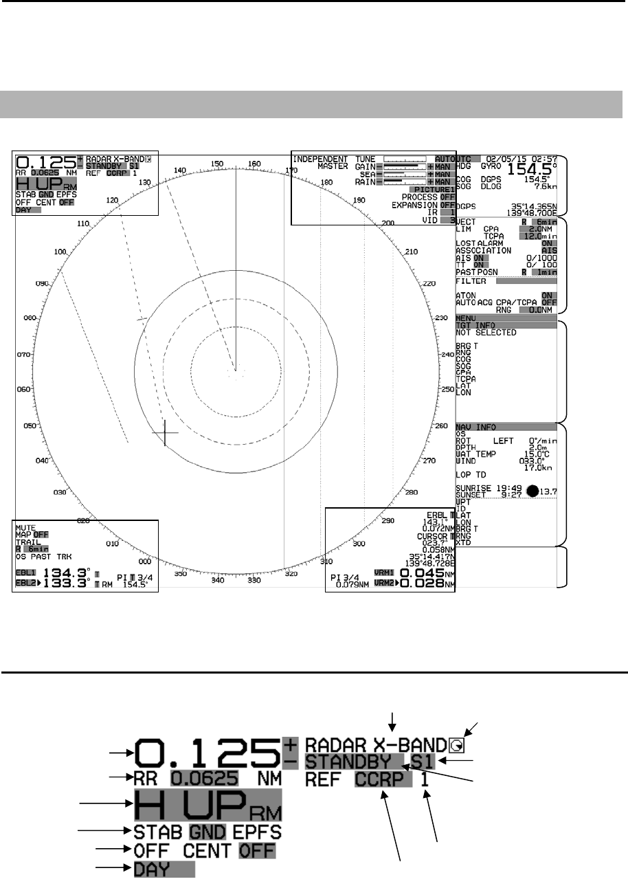
1.1 Radar Display
Upper left corner
EBL1
Upper left corner Upper right corner
Lower left corner Lower right corner
Own ship
data
Tar ge
t
status
Target and
MAP
Information
area
A
ssistant
display
(Navigation
Information)
A
larm
display
area
Heading
line
ERBL
EBL2
(OFFSET)
Range Rings
VRM1
VRM2
PI
PI
PI
PI
Range scale
Range Rings
MODE
STAB
Off center
Day/Night
Pulse width
TX/Standby
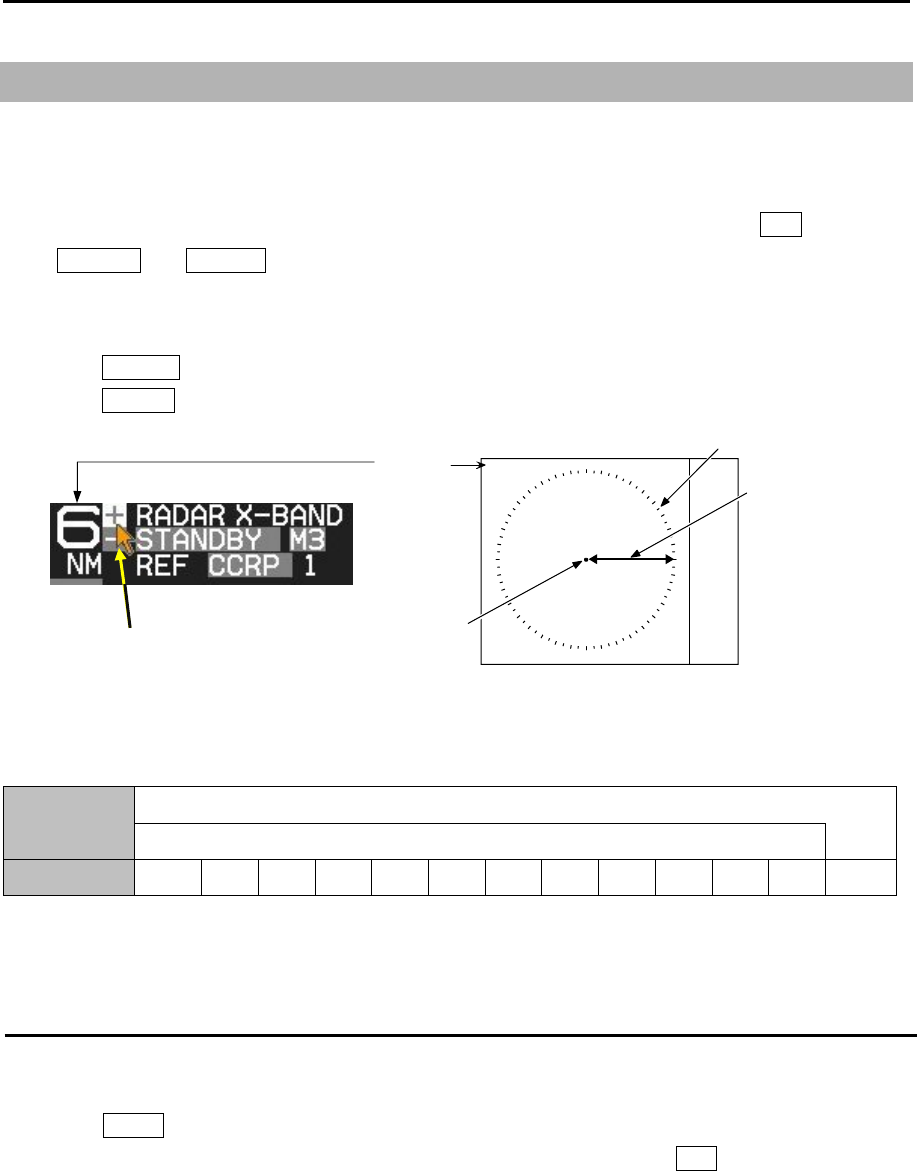
Frequency band Picture freeze
detection
REF position number 1-4
REF position CCRP/ANT
Chapter 1 Display and Operation MDC-7000P/7900P Series
0093169006-05E 1-2
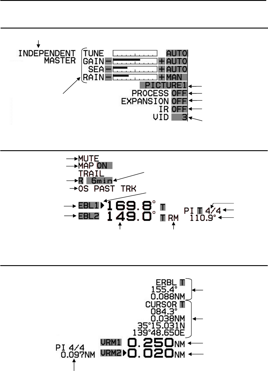
Upper right corner
Lower left corner
Lower right corner
ERBL data
Cursor position data
VRM1 distance
VRM2 distance
Distance of selected No.4 PI
Interference Rejection
setting
Sector MUTE ON
MAP function display
TRAIL TRUE/REL
TRAIL TIME
Own Ship Past Track ON
EBL1
EBL2
EBL1 active mark
EBL bearing Offset EBL move mode TM/RM
Selected PI
Active PI
Bearing of
selected PI
Inter-switch mode
TUNE setting
GAIN setting
SEA setting
RAIN setting
PICTURE setting
PROCESS setting
EXPANSION setting
VIDEO mode setting
MDC-7000P/7900P Series Chapter 1 Display and Operation
0093169006-05E 1-3
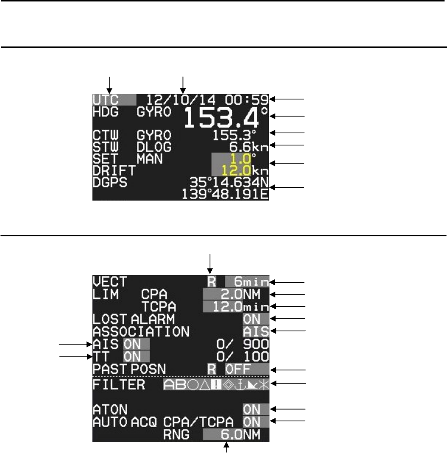
Own ship data
Target status
UTC/LOCAL TIME Date
Day/Month/Year
Time
Heading
CTW or COG
STW or SOG
Set and Drift
Own ship position
Vector REL/TRUE
Vector Time
Limit CPA
Limit TCPA
AIS and TT Lost Alarm
Association setting
AIS ON
TT ON
A
IS and TT Past position
Indication Mode REL/TRUE
Indication Time
A
ctivit
y
AIS Filter Icon
Indication ATON AIS
A
IS Auto Acquisition
by CPA/TCPA
A
IS Auto Acquisition
by Range (0.0NM to 64.0NM)
Chapter 1 Display and Operation MDC-7000P/7900P Series
0093169006-05E 1-4
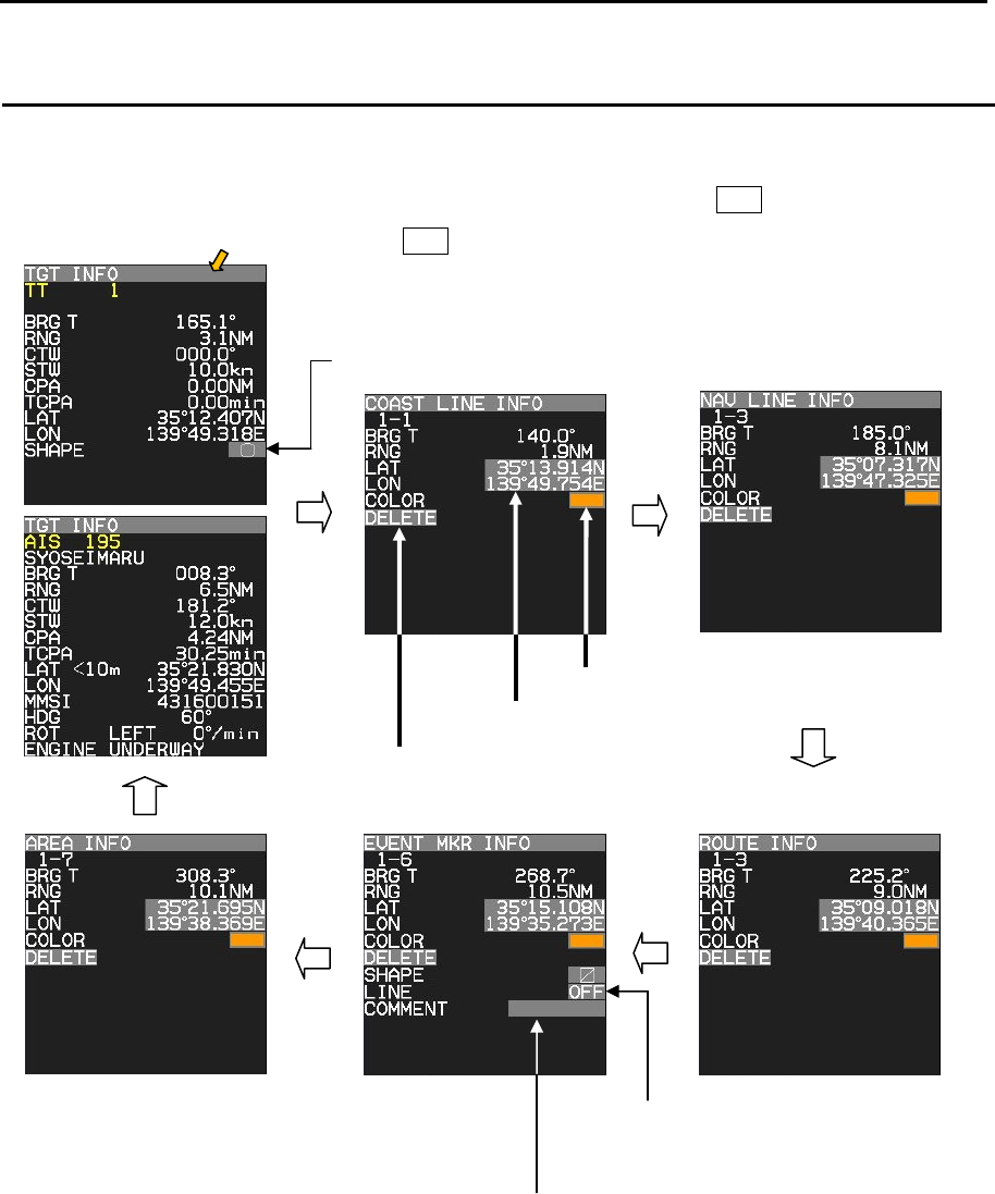
Target and MAP information area
Selected AIS, TT or MAP (COAST LINE, NAV LINE, ROUTE, EVENT MKR and AREA) information is
displayed, this data can be changed by selecting with cursor and pressing ENT key.
Change TT shape
Cursor and press ENT key.
Edit LAT/LON data
Change Color
Deletion of indication data
Line indication between own ship
position and marker point.
Comment input
MDC-7000P/7900P Series Chapter 1 Display and Operation
0093169006-05E 1-5
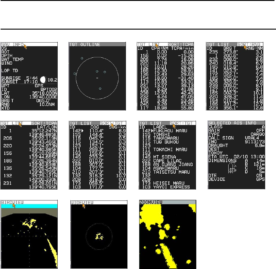
Assistant display (Navigation information)
Selection values are NAV INFO, TGT OUTLINE, TGT LIST (CPA/TCPA), TGT LIST (BRG/RNG), TGT
LIST (LAT/LON), TGT LIST (COG/SOG), TGT LIST (LABEL), SELECTED AIS INFO, BIRDVIEW,
WIDEVIEW and ZOOMVIEW.
TGT LIST can be sorted by CPA, TCPA, RNG, TGT and SEL
CPA: It is displayed with the nearest first from the top of display.
TCPA: It is displayed with the shortest first from the top of display.
RNG: It is displayed with the nearest first the top of display
TGT: It is displayed with the nearest to the selected target first from the top of display.
SEL: It is displayed with the selected target first from the top of display.
NAV INFO TGT OUTLINE TGT LIST CPA/TCPA TGT LIST BRG/RNG
TGT LIST LAT/LON TGT LIST COG/SOG TGT LIST LABEL SELECTED AIS INFO
BIRDVIEW WIDEVIEW ZOOMVIEW
Chapter 1 Display and Operation MDC-7000P/7900P Series
0093169006-05E 1-6
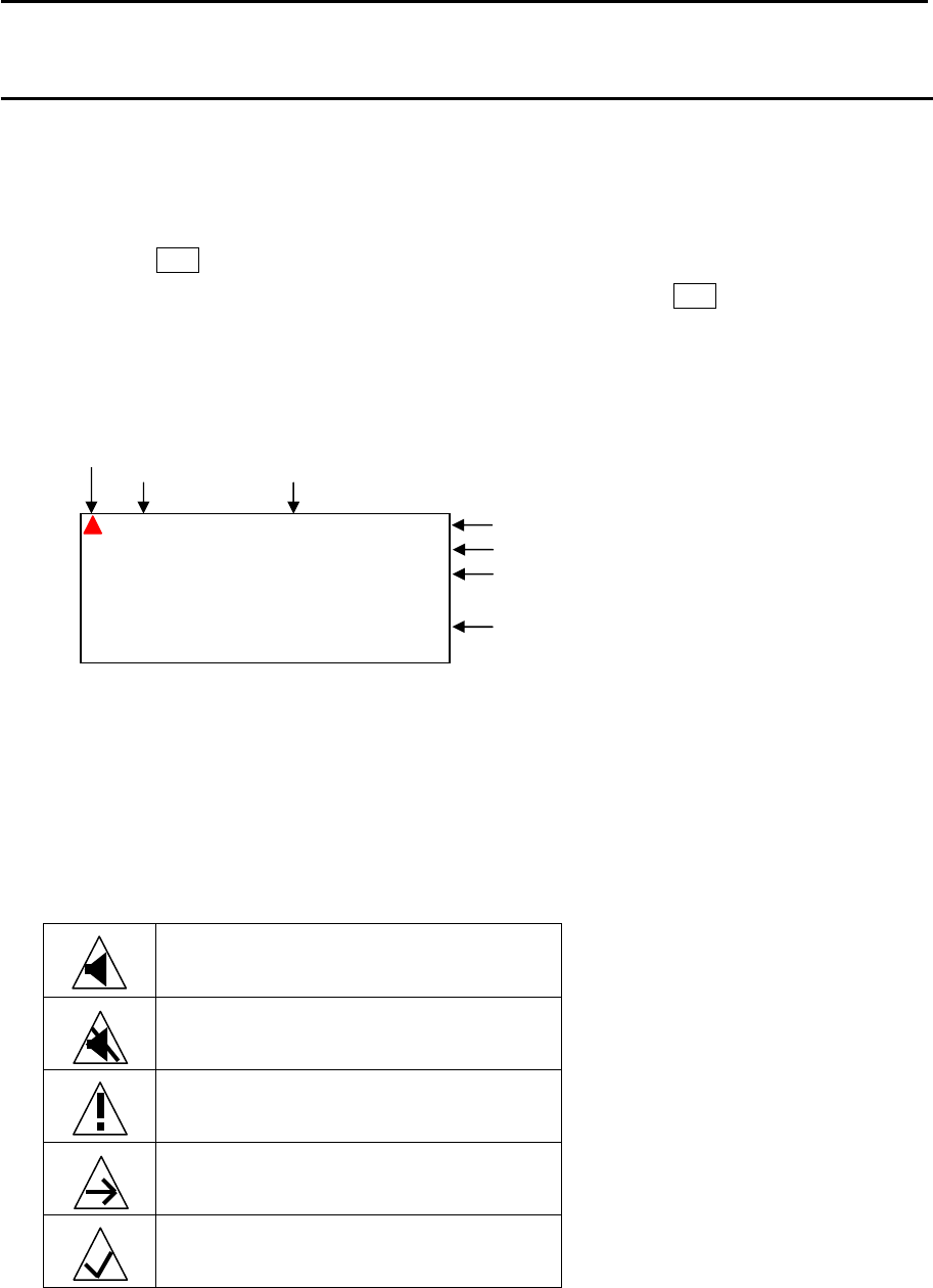
Alarm display area
When a malfunction or operation error has been detected in the radar, alarm message will appear at
the alarm display area.
Abnormalities are categorized as [ALARM], [WARNING] and [CAUTION]. When these messages
actually appear and there is something wrong with radar, record the alarm details by type, location and
status and press OFF key. The alarm sound (when ALARM and WARNING) and display will disappear.
Multiple errors may be displayed one by one. Record all alarms and press OFF key for every alarm.
Alarm list: Refer to 9.8 About alarms “Alarm list”.
ALARM (Displayed with red)
In case of unacknowledged alarm, icon and ALARM of priority will be flashing, and 3 short audible
signals will be repeating every 7 sec.
In case of silenced alarm, audible signals will be stopping. If silenced alarm condition keeps more than
30 sec. silence alarm condition will cancel.
Type of ALARM icons
Active
Unacknowledged alarm
Active
Silenced alarm
Active
Acknowledged alarm
Active
Responsibility transferred alarm
Rectified
Unacknowledged alarm
Category (A, B or C)
A
larm ID (0 to 9999: Specified by the IMO,
10000 to 9999999: Peculiar to a maker)
Time of alarm occurrence
ID of cause device, Source of alarm
A
lert management
icons
Message
A
LARM
A
9999999
UTC 15 / 10 / 14 16:23
RADAR RADAR 1
MESSAGE
Priority
MDC-7000P/7900P Series Chapter 1 Display and Operation
0093169006-05E 1-7
WARNING (Displayed with yellowish orange)
In case of unacknowledged alarm, icon and WARNING of priority will be flashing, and 2 short audible
signals will be repeating every 60 sec.
Type of WARNING icons
Active
Unacknowledged warning
Active
Silenced warning
Active
Acknowledged warning
Active
Responsibility transferred warning
Rectified
Unacknowledged warning
CAUTION (Displayed with yellow)
In case of CAUTION status, icon and CAUTION of priority is not flashing and audible signal is silent.
Type of CAUTION icon
Caution
WARNING A 9999999
UTC 15 / 10 / 14 16:23
RADAR 1
MESSAGE
CAUTION A 9999999
UTC 15 / 10 / 14 16:23
RADAR RADAR 1
MESSAGE
Chapter 1 Display and Operation MDC-7000P/7900P Series
0093169006-05E 1-8
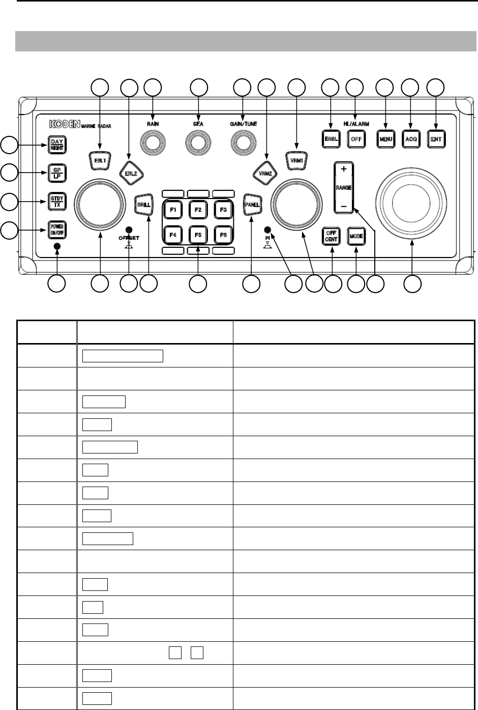
1.2 Operation Unit
No. Key/knob name Contents
1 POWER ON/OFF key Turn on and off the power.
2 POWER lamp Status of power on.
3 STBY/TX key Transmission on and off.
4 SP/LP key Change transmission pulse width.
5 DAY/NIGHT key Change echo color, day or night.
6 EBL1 key EBL1 on and off.
7 EBL2 key EBL2 on and off.
8 BRILL key Display brilliance adjust mode on and off.
9 EBL/BRILL knob Adjust EBL1, EBL2 or display brilliance.
10 OFFSET lamp Status lamp of offset EBL mode on.
11 RAIN knob Reduce rain clutter.
12 SEA knob Reduce sea clutter.
13 GAIN knob Adjust radar receiver gain.
14 FUNCTION keys F1 - F6 Quick short cut menu access.
15 VRM1 key VRM1 on and off.
16 VRM2 key VRM2 on and off.
28
1
25 26
2
3
4
5
6 7
14
9 8 10
13 11
17 18
19
12 15 16 20 21 22 23 24
27

MDC-7000P/7900P Series Chapter 1 Display and Operation
0093169006-05E 1-9
17 PANEL key Control panel brilliance adjustment.
18 VRM/PANEL knob Adjust VRM1, VRM2 or panel brilliance.
19 PI lamp Status lamp of parallel index lines.
20 ERBL key Electronic range and bearing line on and off.
21 OFF key Erase heading line, stop alarm sound, etc.
22 MENU key Turn MENU on and off.
23 ACQ key Start manual TT acquisition.
24 ENT key Key most often used to make a selection.
25 RANGE key Change radar range scale.
26 MODE key Change display mode HU/NU/CU.
27 OFF CENT key Off center mode on and off.
28 TRACKBALL Used to make MENU selection and move cursor.
Chapter 1 Display and Operation MDC-7000P/7900P Series
0093169006-05E 1-10
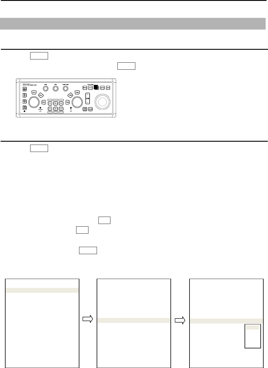
1.3 Menu usage
Turn MENU on and off
1 Press MENU key, “Menu” display on the right side of the display.
2 “Menu” display is turned off by pressing MENU key again.
Select menu item
1 Press MENU key and “Main menu” will show on the display. Select one of main menu items by
moving the trackball up or down.
2 Move the trackball to the right after making selection in main menu and the sub menu will show on
the display.
3 Select a sub menu item by moving the trackball up or down.
4 Move the trackball to the right after making selection in sub menu and value of selected item will
show.
5 Select desired value, then press ENT key.
Note: Pay attention that ENT key must be pressed for selected item to take effect.
6 Move trackball to the left to return to previous menu.
To exit from menu, press MENU key again.
<Example of menu display>
Note: “Menu” setup value is stored in the non-volatile memory inside the radar. Therefore, no setup
operation is required after power is turned on.
MENU
ECHO >
TRAIL >
DISPLAY >
ALARM >
TARGET >
NAV TOOL >
MAP >
BRILL >
SYSTEM >
MAINTENANCE >
>ECHO
PICTURE MODE
PICTURE1
PROCESS
OFF
EXPANSION 2
IR OFF
VIDEO CONTRAST 3
NOISE REJ OFF
COLOR REJ OFF
PULSE WIDTH >
SART OFF
PICTURE RESET >
>ECHO
PICTURE MODE
PICTURE1
PROCESS
OFF
EXPANSION 2
IR OFF
VIDEO CONTRAST 3
NOISE REJ OFF
COLOR REJ OFF
PULSE WIDTH >
SART OFF
PICTURE RESET >
OFF
1
2
3
MDC-7000P/7900P Series Chapter 1 Display and Operation
0093169006-05E 1-11
Note: About the shaded menu:
[INTER-SWITCH] in [SYSTEM] menu, and [SECTOR MUTE], [BACKUP], [TOTAL HOUR] and [TX
HOUR] in [MAINTENANCE] menu are not available during transmission, therefore they are greyed
out.
Note: [MAINTENANCE] is protected menu and it is normally not displayed.
Display [MAINTENANCE] menu
1 Press MENU key to display “Menu”.
Select [SYSTEM] => [PROTECT MENU] => [ON], and press ENT key after selection.
2 [PROTECT MENU xxxx] => turn trackball to right, [Set password (xxxx)], and press ENT key after
setting.
Initial password value (xxxx): (0000).
Menu display disappears once after a correct password is input. Press MENU key once again to use
“Menu”.
How to change PASSWORD
After [PROTECT MENU] => [ON], select [MAINTENANCE] => [PASSWORD] =>
[New PASSWORD input], and press ENT key.
Selection values: 0000 to 9999
Note: The new password is active after a restart.
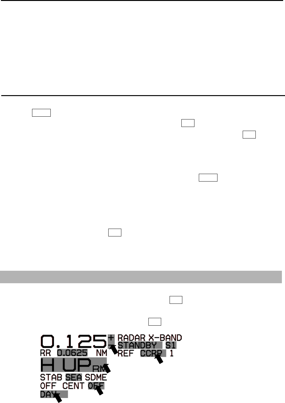
1.4 Cursor Access usage
Basic radar functions can be operated by using trackball and ENT key without using menu.
This function is effective for the operation with USB Mouse/Trackball from the remote place.
Move cursor on a grey item with trackball, then press ENT key.
- This page intentionally left blank.-
MDC-7000P/7900P Series Chapter 2 Radar Basic Operation
0093169006-05E 2-1
Chapter 2 Radar Basic Operation
2.1 Power ON/OFF
Power ON
Press POWER ON/OFF key located at the lower left corner of the Operation unit. Radar system is
turned on with beep sound.
After power on, radar model name and preheating countdown time will appear at the center of the
display.
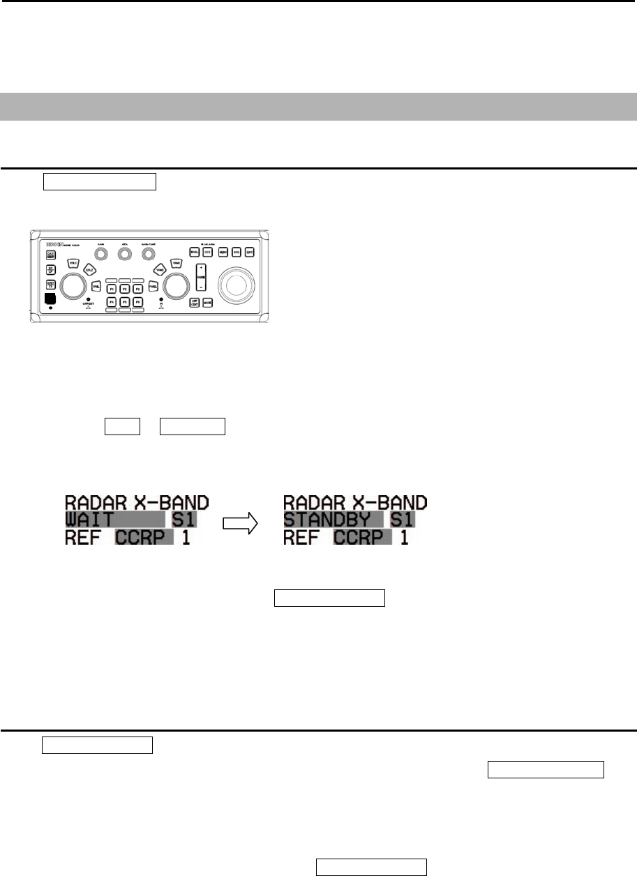
Wait for 120 sec. (*1) or 180 sec. (*2) until preheating countdown time has disappeared, and status
changes from WAIT to STANDBY at the upper left of the display.
(*1) MDC-7012P/7912P
(*2) MDC-7025P/7925P
The brilliance of the display is set to the previous value of the last power off.
During operation, “POWER LAMP” under POWER ON/OFF key lights up red.
Note: The power source shall not be turned off until operational window is displayed.
Power OFF
Press POWER ON/OFF key for two sec. for power off.
“SHUTDOWN” message appears at the center of the display, release POWER ON/OFF key
immediately, and few sec. later will completely power off.
Note:
• The power source shall be turned off by pressing POWER ON/OFF key.
When the ship’s power source is lost during operation, an important setup data may be lost
• After radar has been turned off, wait at least five seconds before turning it back on.
Chapter 2 Radar Basic Operation MDC-7000P/7900P Series
0093169006-05E 2-2
2.2 Change Brilliance
Display Brilliance
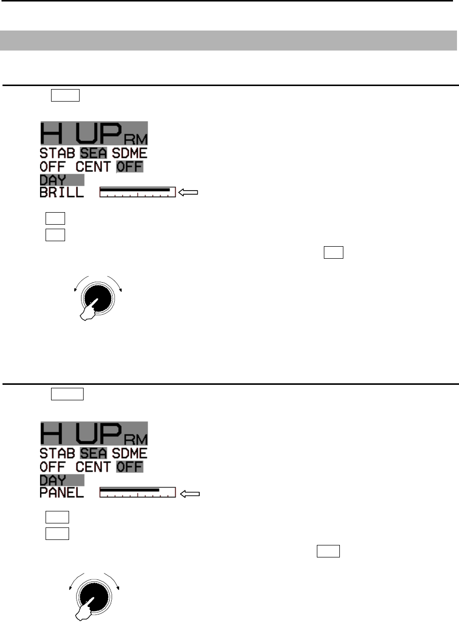
1 Press BRILL key.
2 The BRILL adjustment window will appear in the upper left of the display.
3 Turn EBL knob clockwise to increase the display brilliance.
Turn EBL knob counterclockwise to decrease the display brilliance.
The display brilliance can also be changed in five steps by pressing EBL knob.
Operation unit Brilliance
1 Press PANEL key.
2 The PANEL adjustment window will appear in the upper left of the display.
3 Turn VRM knob clockwise to increase the lighting of the panel brilliance.
Turn VRM knob counterclockwise to decrease the lighting of the panel brilliance.
The panel brilliance can also be changed in five steps by pressing VRM knob.
BRILL adjustment window
PANEL adjustment window
Push
Brighte
r
Darker
EBL knob
Press
Push
Brighte
r
Darke
r
VRM knob
Press
MDC-7000P/7900P Series Chapter 2 Radar Basic Operation
0093169006-05E 2-3
2.3 Transmission
Transmission ON
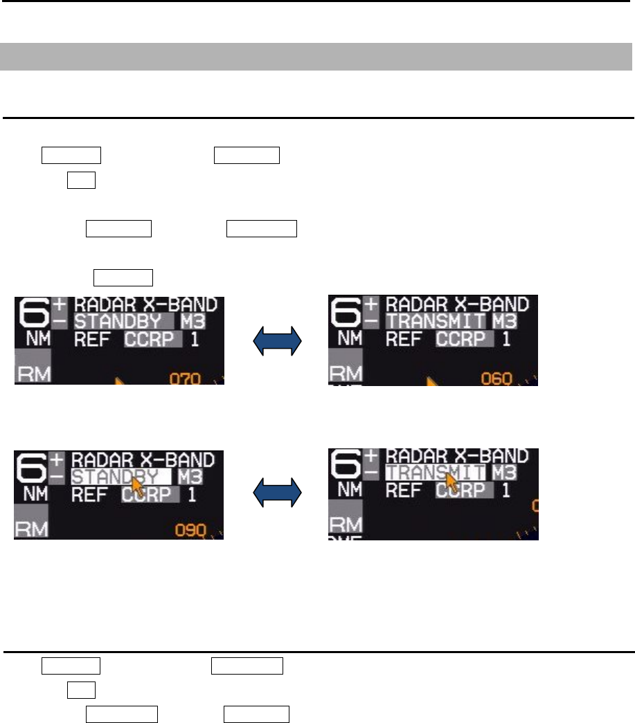
After preheating time countdown is completed, the radar can be placed in transmit mode.
Press STBY/TX key, or select the STANDBY box at the upper left corner of the display using trackball
and press ENT key.
Radar system will start transmission.
The status of STANDBY changes to TRANSMIT.
Transmission OFF
Press STBY/TX key, or select the TRANSMIT box at the upper left corner of the display using trackball
and press ENT key to stop transmission.
The status of TRANSMIT returns to STANDBY at upper left of the display.
Operation of STBY/TX key
Operation of trackball
Chapter 2 Radar Basic Operation MDC-7000P/7900P Series
0093169006-05E 2-4
2.4 Tuning method
The transmitting and receiving frequency of this radar may become detuned by environmental
changes.
This result in “detuning” of the gain and the same echo images may show weaker, even if the setup is
the same as before.
Tuning method can be changed directly in the upper right of the display, with trackball and ENT key,
without using menu function.
Tuning menu operation method, refer to 4.2.1 Tune adjustment of Installation manual.
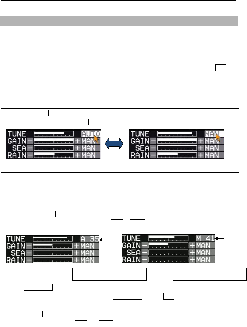
Change MAN (manual) and AUTO
Move cursor to the MAN or AUTO box (whichever is shown) of tune indicator at upper right of the
display using trackball and press ENT key.
Optimized value setup method
Adjustment shall be performed based on stable echo object such as from land. (Land is used in
following explanation.)
1 Set RAIN and SEA at 0.
2 Set lower GAIN until land echo almost disappears.
3 Press GAIN/TUNE knob until light around knob turns red.
Tune value box will appear on the place of MAN or AUTO box of tune indicator.
4 Turn GAIN/TUNE knob clockwise or counterclockwise to get the strongest land echo.
5 When tune adjustment is completed, press GAIN/TUNE knob or ENT key to save setting data to
internal memory.
Light around GAIN/TUNE knob will turn green.
6 Repeat step 3 to 5 for both MAN and AUTO modes.
AUTO tune mode value box MAN tune mode value box
MDC-7000P/7900P Series Chapter 2 Radar Basic Operation
0093169006-05E 2-5
2.5 Change range scale
The coverage area can be changed by changing range scale.
Larger the value of range the more coverage area expands. (The target image will become smaller.)
The range scale value and range rings value are indicated at the upper left on the display.
Range scale can be changed directly at the upper left of the display, with trackball and ENT key, without
using RANGE+ and RANGE- key.
Range is changed centering on the antenna position.
1 Press Range + key to zoom out the picture, and to observe a wider area.
Press Range - key to zoom in the picture, to magnify and to observe closer to Antenna position.
Model-specific ranges are as shown below.
Model name MDC-7025P/7925P (Max. output : 25 KW)
MDC-7012P/7912P (Max. output : 12 KW)
Range(NM) 0.125 0.25 0.5 0.75 1.5 3 6 12 24 32* 48 64* 96**
* 32NM and 64NM is for 12kW only.
** 96NM is for 25kW only.
Change range unit (NM / km)
The unit of range measurement can be changed from nautical miles (NM) to metric (km).
1 Press MENU key to display “Menu”.
Select [DISPLAY] => [RANGE UNIT] => select [NM] or [km], and press ENT key.
When changing to [km] range unit, Range and Cursor range unit will be changed.
1.5
Indicated distance
*Bearing scale
Range
ANT position
Trackball operation
Cursor point
Chapter 2 Radar Basic Operation MDC-7000P/7900P Series
0093169006-05E 2-6
2.6 Adjust receiver gain (GAIN)
It is recommended to adjust [GAIN] in the upper right side of the display to have the evenly scattered
vague background noise with low intensity in the PPI.
Lower than required [GAIN] may result in missing small vessels and buoys.
Higher [GAIN] than required may result in difficult discrimination between small ships and densely
displayed high level background noise.
Under some situation, desired target object may be masked by side lobe of antenna directivity or false
echo by multi path.
Lower [GAIN] until masked target echo can be recognized outside of the area where 2.7 “Reject sea
clutter (anti-SEA)” is effective.
However since lower [GAIN] tends to lose weak target echo, try to return the [GAIN] to original position
each time [GAIN] is changed to maintain target recognition. In the short distance area where anti-SEA
is effective, recognize target by adjusting MAN SEA.
When suppressing RAIN clutter (rain & snow), adjust GAIN knob and RAIN knob side by side.
[GAIN] state is displaying in the upper right of the display.
Selection of MAN GAIN and AUTO GAIN
By GAIN knob
When the GAIN knob is pressed, AUTO GAIN and MAN GAIN change alternately.
By trackball
1 Move cursor on the MAN or AUTO display (whichever is shown) at right side of [GAIN] on the top
of the display.
2 Press ENT key to change AUTO or MAN as appropriate.
AUTO adjustment of GAIN
When AUTO GAIN is set, [GAIN] is adjusted automatically.
Note: AUTO GAIN may remove weak target echoes, or too much sea clutter may be on the display, turn
GAIN knob clockwise or counterclockwise to adjust AUTO GAIN effectively.
If not setup properly, adjust AUTO GAIN settings by referring to 4.5.3 Setup GAIN MIN and MAX
mode of Installation manual.
MDC-7000P/7900P Series Chapter 2 Radar Basic Operation
0093169006-05E 2-7
MAN adjustment of GAIN
When MAN GAIN is selected, GAIN can be adjusted manually.
1 Turn GAIN knob clockwise to increase receiving gain.
Turn GAIN knob counterclockwise to decrease receiving gain.
Up
Down
Gain
Note:
• Decrease gain for shorter range and dense targets.
• Increase gain for long range targets and small target however take care in not using too much gain
and losing targets in the surrounding noise.
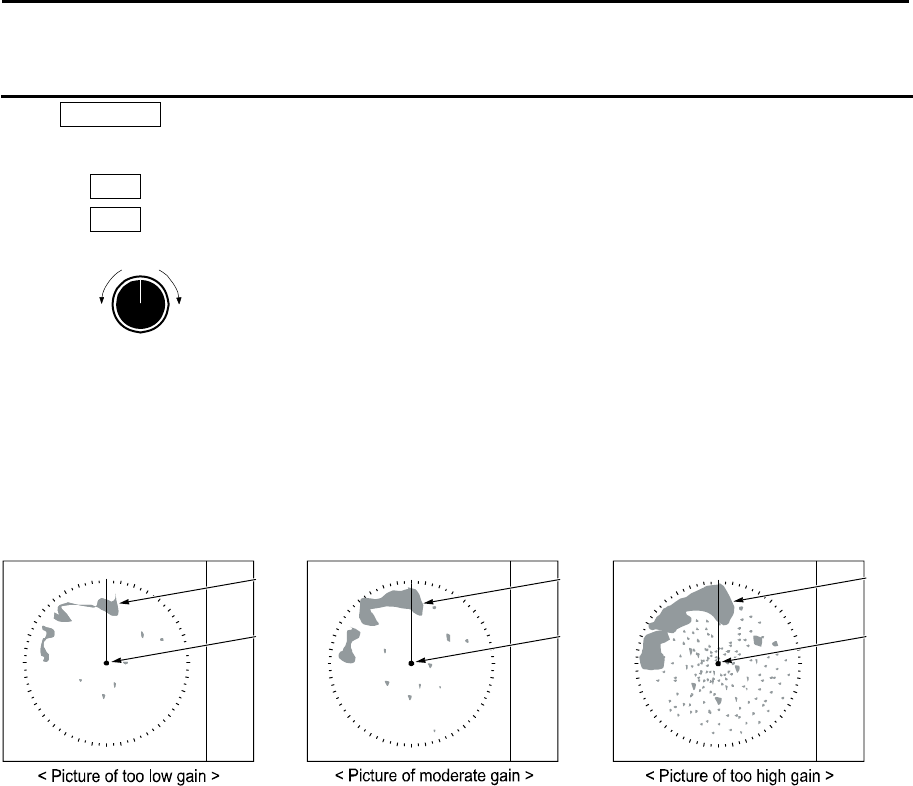
Own
ship
Land
Result picture after adjustment a [GAIN] knob
Own
ship
Land
Own
ship
Land
Chapter 2 Radar Basic Operation MDC-7000P/7900P Series
0093169006-05E 2-8
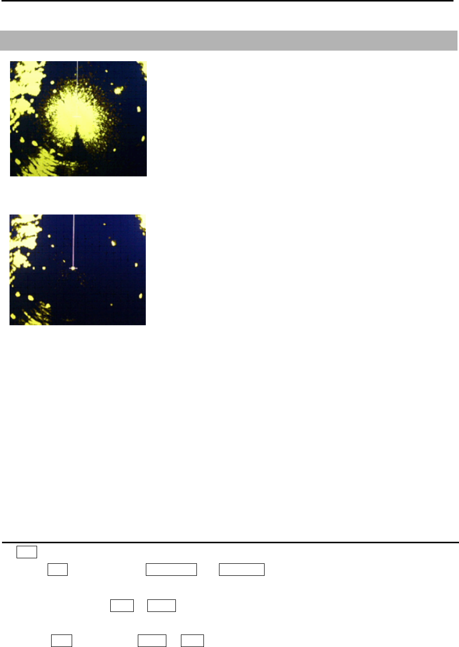
2.7 Reject sea clutter (anti-SEA)
MAN (manual) SEA and AUTO (automatic) SEA are provided for
anti-SEA function. On the rough sea, SEA clutter noise appears
around antenna position (center spot), and short distant targets
are masked and not recognizable. In that case, anti-SEA function
suppresses sea clutter noise and reveals masked target echoes.
Recommended adjustment of anti-SEA is to adjust to make
echoes from sea clutter vaguely displayed by low (weak) level.
If anti-SEA level is too high to show sea clutter noise, short
distance gain is over suppressed and it may result in loss of
targets like buoys and small ships.
On the other hand, if anti-SEA level is too low, clutter noise around
antenna position (center spot) is displayed by high intensity level
and it makes difficult to discriminate small ships and buoys from
sea clutter.
Anti-SEA is effective to suppress false echoes and ground clutter
in short distance. However adjustment of GAIN should be used
beyond effective coverage of anti-SEA.
If target echoes are masked by excessive false echoes within anti-SEA effective area, then adjust MAN
SEA to confirm it. Excessive anti-SEA may lose echoes from small ships and buoys. So, return to
appropriate anti-SEA level for normal use.
Note:
• Small targets become harder to detect when [SEA] is used together with [RAIN]. Therefore, please
adjust them carefully.
• The echo process (refer to 2.23 Echo process) is useful to reject sea clutter. Be careful, when the
echo process is active, high-speed targets are harder to detect than stationary ones.
Selection of MAN SEA and AUTO SEA
By SEA knob
When the SEA knob is pressed, AUTO SEA and MAN SEA change alternately.
By trackball
1 Move cursor on the MAN or AUTO display (whichever is shown) at right side of [SEA] on the top of
the display.
2 Press ENT key to display AUTO or MAN as appropriate.
SEA clutter at center
After Adjusted MAN SEA
MDC-7000P/7900P Series Chapter 2 Radar Basic Operation
0093169006-05E 2-9
AUTO adjustment of SEA
When AUTO SEA is set, anti-SEA is adjusted automatically.
Note: AUTO SEA may erase weak target echoes. If excessive sea clutter erasing or too much clutter is
observed, turn SEA knob clockwise or counterclockwise to adjust AUTO SEA effectively.
If not setup properly, adjust it by referring to 4.5.3 Setup GAIN MIN and MAX mode of Installation
manual.
In case there are strong echo targets such as in the harbor or canal, anti-SEA tends to suppress
excessively, use MAN SEA in that case.
Manual adjustment of SEA
When MAN SEA is selected, anti-SEA can be adjusted manually.
By using SEA knob, suppress this effect and make targets seen easier.
[SEA] state is displayed in the upper right of the display.
1 Turn SEA knob clockwise to increase anti-sea clutter effect.
Turn SEA knob counterclockwise to decrease anti-sea clutter effect.
2 Turn SEA knob clockwise until even low (weak) SEA clutter is displayed by observing the display.
3 Adjust SEA knob from time to time to get low (weak) SEA clutter on the display as intensity of sea
clutter changes as time passes.
High
Low
SE
A
Note:
• When waves do not affect the result, turn the knob fully counterclockwise.
• This function reduces gain in closest ranges. Too much sea clutter may result in actual targets being
lost.
• Manual SEA user keep watching and adjusting SEA with changing conditions.
• If SEA and anti-RAIN are used in combination, then small targets will be less visible.
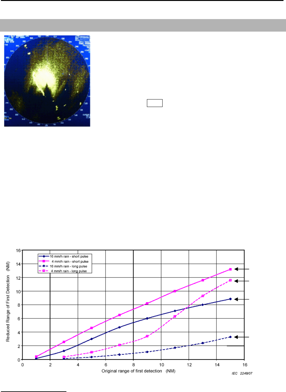
Chapter 2 Radar Basic Operation MDC-7000P/7900P Series
0093169006-05E 2-10
2.8 Reject rain/snow clutter (anti-RAIN)
In rain or snow, targets become hard to be seen as a result of
unwanted weather reflection.
Rain or snow image appears as a large target echo with
surrounding mid gradation rim as shown in the picture.
Anti-RAIN is available MAN and CFAR.
Adjustment of MAN (manual) and CFAR (Constant False Alarm
Rate) by turning RAIN knob suppresses clutter, and helps to see
targets clearly.
MAN is effective for suppression of rain and snow.
CFAR is effective for suppression of sea, rain and snow clutter.
[RAIN MODE] can be changed directly in the upper right of the display without using menu function.
Note:
• Small target becomes harder to detect when [RAIN] is used together with [SEA]. Therefore, please
adjust them carefully.
• The echo process (refer to 2.23 Echo process) is useful to reject rain clutter. Be careful, when the
echo process is active, high-speed targets are harder to detect than stationary ones.
• The performance of radar detection range is degraded by rain as shown in the figure below.
The details of the figure (An example of 6NM range)
A target which was able to observe at 6 NM (Original range of first detection), can only be detected at
the ranges (Reduced Range of First Detection) shown below in rain condition.
4 mm/h rain (short pulse): approx. 5.6 NM 4 mm/h rain (long pulse): approx. 1.5 NM
16 mm/h rain (short pulse): approx. 3.9 NM 16 mm/h rain (long pulse): approx. 0.5 NM
Rain clutter
4 mm
/
h rain
(short pulse)
4 mm
/
h rain
(long pulse)
16
mm
/
h rain
(short pulse)
16
mm
/
h rain
(long pulse)
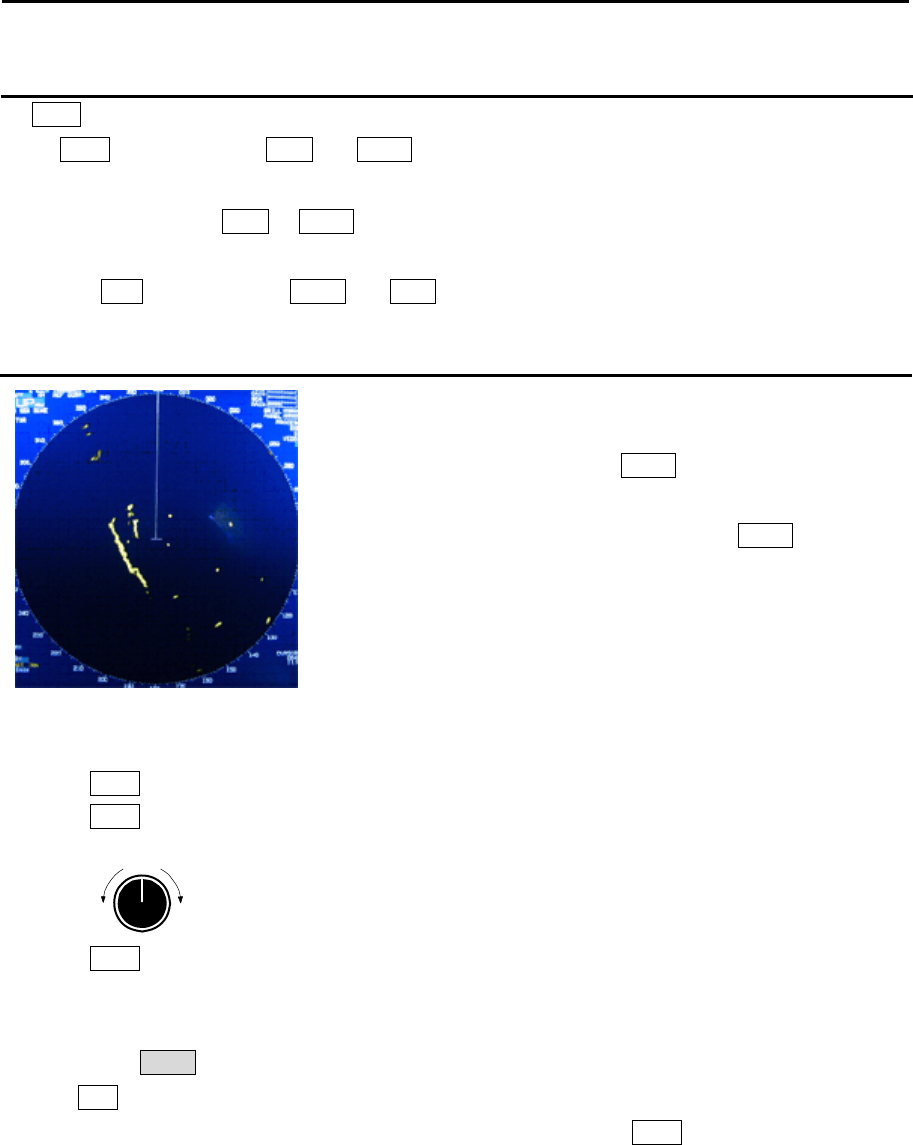
MDC-7000P/7900P Series Chapter 2 Radar Basic Operation
0093169006-05E 2-11
Changing method of CFAR and MAN
By RAIN knob
When RAIN knob is pressed, MAN and CFAR change because of the alternation.
By trackball
1 Move cursor on the MAN or CFAR display (whichever is shown) at right side of [RAIN] on the top
of the display.
2 Press ENT key to alternate CFAR and MAN.
CFAR (Constant False Alarm Rate) adjustment
CFAR function is used to suppress of sea, rain and snow clutter
easily.
CFAR function is active when CFAR is indicated at the upper
right side of the display.
Level of CFAR is indicated on the left side of CFAR indication.
1 Turn RAIN knob clockwise to increase anti-clutter effect.
Turn RAIN knob counterclockwise to decrease anti-clutter effect.
Strong
Weak
RAIN
2 Turn RAIN knob clockwise to get even low (weak) clutter while watching the display.
Note:
• In the case of CFAR mode, the gain adjustment is not possible.
Adjust SEA knob to suppress remaining sea clutter.
• In typical environment CFAR should be turned all the way down via RAIN knob, and no white level
should be indicated by CFAR window.
• Turning the knob to the right shows the targets hidden in the rain/snow image, but care shall be taken
that small target may be hidden and not displayed if over adjusted.
• If there are strong echo targets such as in the harbor or channel, CFAR tends to suppress targets
excessively. In that case, change CFAR to MAN and use MAN SEA in addition.
After CFAR adjustment
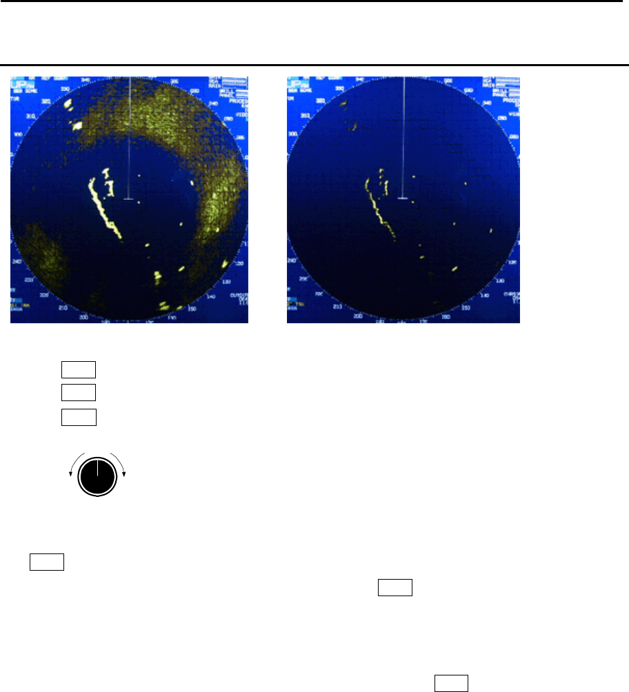
Chapter 2 Radar Basic Operation MDC-7000P/7900P Series
0093169006-05E 2-12
RAIN MAN (manual) adjustment
1 Turn RAIN knob clockwise to increase anti-clutter effect.
Turn RAIN knob counterclockwise to decrease anti-clutter effect.
Turn GAIN knob clockwise until sea clutter is visible on the display.
Strong
Weak
RAIN
2 Use anti-SEA (AUTO SEA or MAN SEA).
3 While observing the display, suppress RAIN clutter outside of anti-SEA effective area by turning
RAIN knob clockwise. Adjust RAIN so that sea clutter is lightly visible.
4 Intensity of RAIN clutter is affected by weather. Adjust by RAIN knob according to weather change
by watching the display.
Note:
• In typical environment RAIN should be turned all the way down via RAIN knob, and no white level
should be indicated by RAIN window.
• Turning the knob to the right shows profiles of the targets hidden in the rain/snow image, but care shall
be taken that small target may be hidden and not displayed.
• Small target becomes harder to detect when RAIN is used together with SEA.
After adjusted anti-SEA After adjusted anti-SEA & RAIN MAN
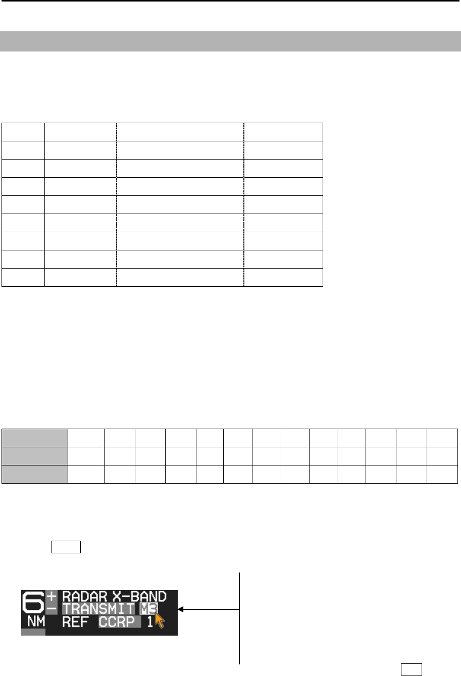
MDC-7000P/7900P Series Chapter 2 Radar Basic Operation
0093169006-05E 2-13
2.9 Change transmission pulse width (SP/LP)
This radar provides a function capable of achieving suitable target detection by manually changing the
transmission pulse width.
Eight different pulse widths are available.
Pulse width Pulse repetition frequency IF Band width
S1 0.08μs 2600Hz 15MHz
S2 0.15μs 2600Hz 15MHz
M1 0.3μs 2400Hz 15MHz
M2 0.4μs 2000Hz 3MHz
M3 0.6μs 1400Hz 3MHz
L1 0.8μs 1000Hz 3MHz
L2 1.2μs 600Hz 3MHz
L3 1.2μs 450Hz 3MHz
The short (narrow) pulse width used in short range has high resolution and is effective for dense
targets.
The long (wide) pulse width used in long range has high gain (sensitivity) and is effective for detecting
small targets.
Two different pulse widths are set by default in the following ranges, 0.75NM, 1.5NM, 3NM and 6NM.
Ranges 0.5NM and below, and 12NM and above are setup with same pulse width in SP and LP.
Note: Refer to 2.29 Pulse width to set pulse width.
Range(NM) 0.125 0.25 0.5 0.75 1.5 3 6 12 24 32* 48 64* 96**
SP mode S1 S1 S1 S1 S2 M1 M3 L2 L2 L2 L2 L3 L3
LP mode S1 S1 S1 S2 M1 M3 L1 L2 L2 L2 L2 L3 L3
* 32NM and 64NM is for 12kW only.
** 96NM is for 25kW only.
1 Press SP/LP key. Two different pulse widths are toggled by each key press.
Current pulse width is shown at the upper left of the display.
Note: Pulse width can be changed directly at the upper left of the display, with cursor and ENT key.
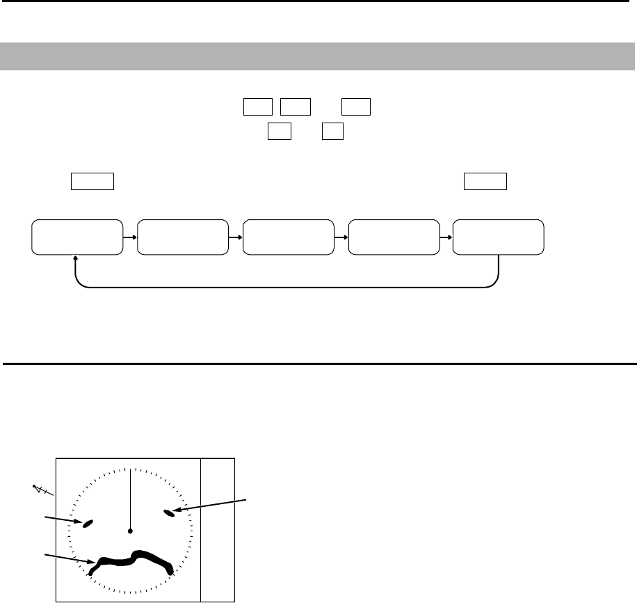
Chapter 2 Radar Basic Operation MDC-7000P/7900P Series
0093169006-05E 2-14
000
060
070
N
Land
Target 1
Target 2
Heading
2.10 Select Display Mode
The display mode is a combination of the bearing indication and the target motion indication.
The bearing is indicated in three ways: HUP, CUP and NUP.
The target motion is indicated in two ways: RM and TM.
1 Press MODE key. The display changes in following order by pressing MODE key. Current display
mode is displayed at the upper left of the display.
H UPRM C UPRM C UPTM N UPRM N UPTM
For H UP (Head up mode)
Heading line is always oriented toward the top of the display.
This mode is based on the bow of the ship and is suitable to monitor targets because targets are seen
as they are in navigating own ship.
When heading signal is connected, H UP works by stabilized mode. (STAB H UP)
Note:
• This is a presentation mode stabilized in azimuth with fixed origin in which the radar image is oriented
“up” toward the top of the bearing scale.
• Radar echoes and tracked targets are shown at their measured distances and moving in a direction
relative to own ship’s heading.
• The heading line points from the CCRP the top of the bearing scale showing own ship’s heading in
true bearing mode.
• The target trails mode can use both functions of true and relative.
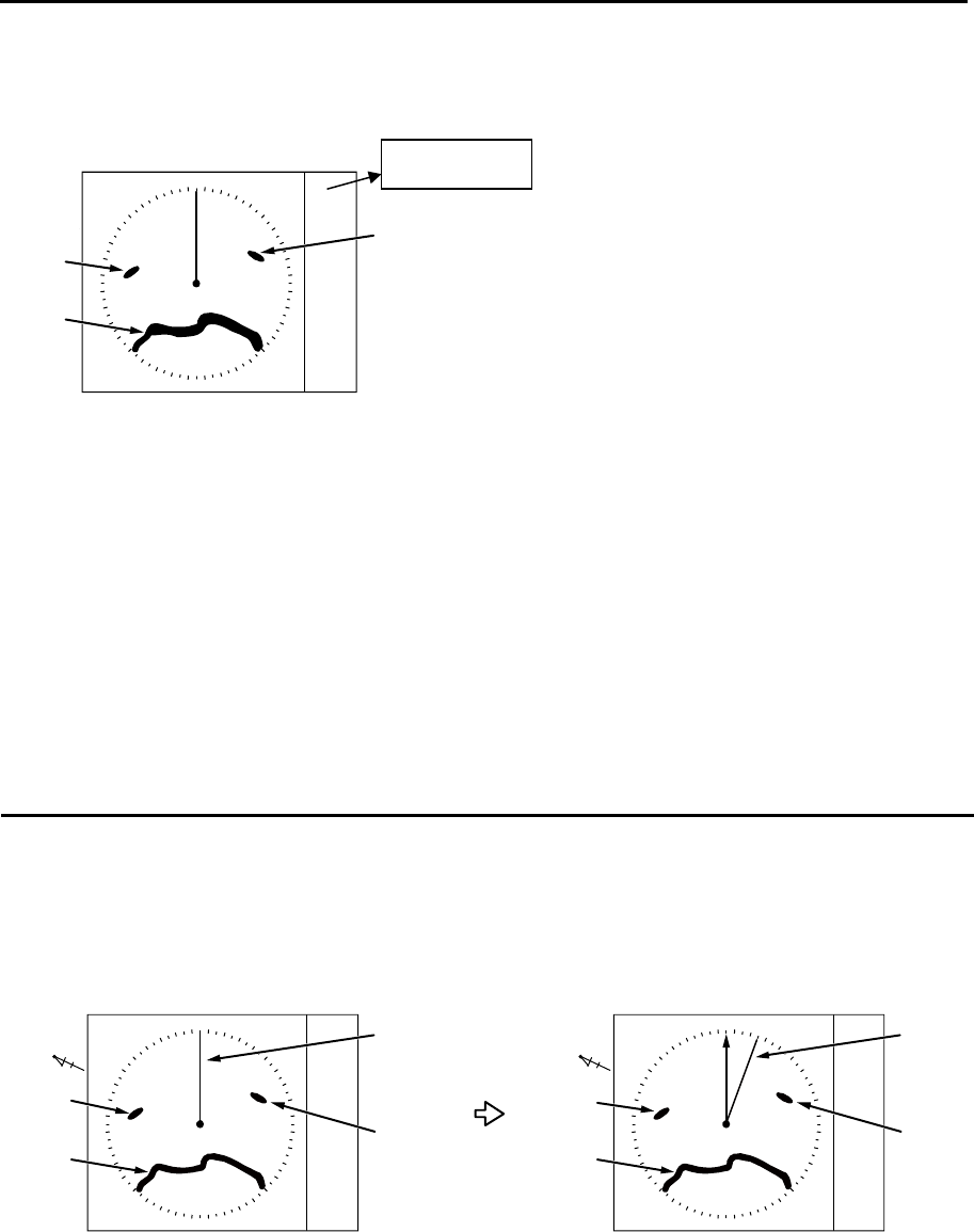
MDC-7000P/7900P Series Chapter 2 Radar Basic Operation
0093169006-05E 2-15
060
000
070
000
080
090
Specified course
< [C UP] selected > < Heading deviated from course >
N
Land
Target 1
Target 2 Target 2
Heading
N
Land
Target 1
Heading
At the time of the XXX.X heading indication of own ship data at upper right of the display, H UP works
by non-stabilized mode.
Note:
• This is a presentation mode not stabilized in azimuth with fixed origin in which the radar image is
oriented “up” toward the top of the bearing scale.
• Radar echoes and tracked targets are shown at their measured distances and moving in a direction
relative to own ship’s heading.
• The heading line points from the CCRP to the top of the bearing scale showing 000 relative bearing.
• Target trails can use only relative mode.
For C UP (Course up mode)
When choosing Course up mode, current heading becomes the course at the top of the display and a
moving heading line indicates actual.
This mode is used to navigate towards a specified course.
It easily shows any deviation of own ship from the specified course.
Note:
• This is an azimuth-stabilized presentation in which the bearing scale can be oriented so that own
ship’s course on the bearing scale is vertically above the CCRP.
• The heading line points from the CCRP to own ship’s referenced heading on the bearing scale.
• If own ship’s heading differs from the course, then the heading line does not point vertically upwards
from the CCRP until the bearing scale is reset (manually or automatically) to reflect the course
alteration.
000
060
070
N
Land
Target 1
Target 2
Heading HDG XXX.X
000
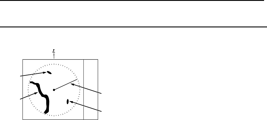
Chapter 2 Radar Basic Operation MDC-7000P/7900P Series
0093169006-05E 2-16
000
N
Land
Target 1
Target 2
Heading
For N UP (North up mode)
This mode always keeps true north at the top of the display.
A north oriented representation makes it easy to reference with a chart.
Note:
• This is an azimuth-stabilized presentation in which north on the bearing scale remains fixed vertically
above the CCRP.
• The heading line points from the CCRP to own ship’s referenced heading on the bearing scale.
• The true bearing of any target on the display is measured from north.
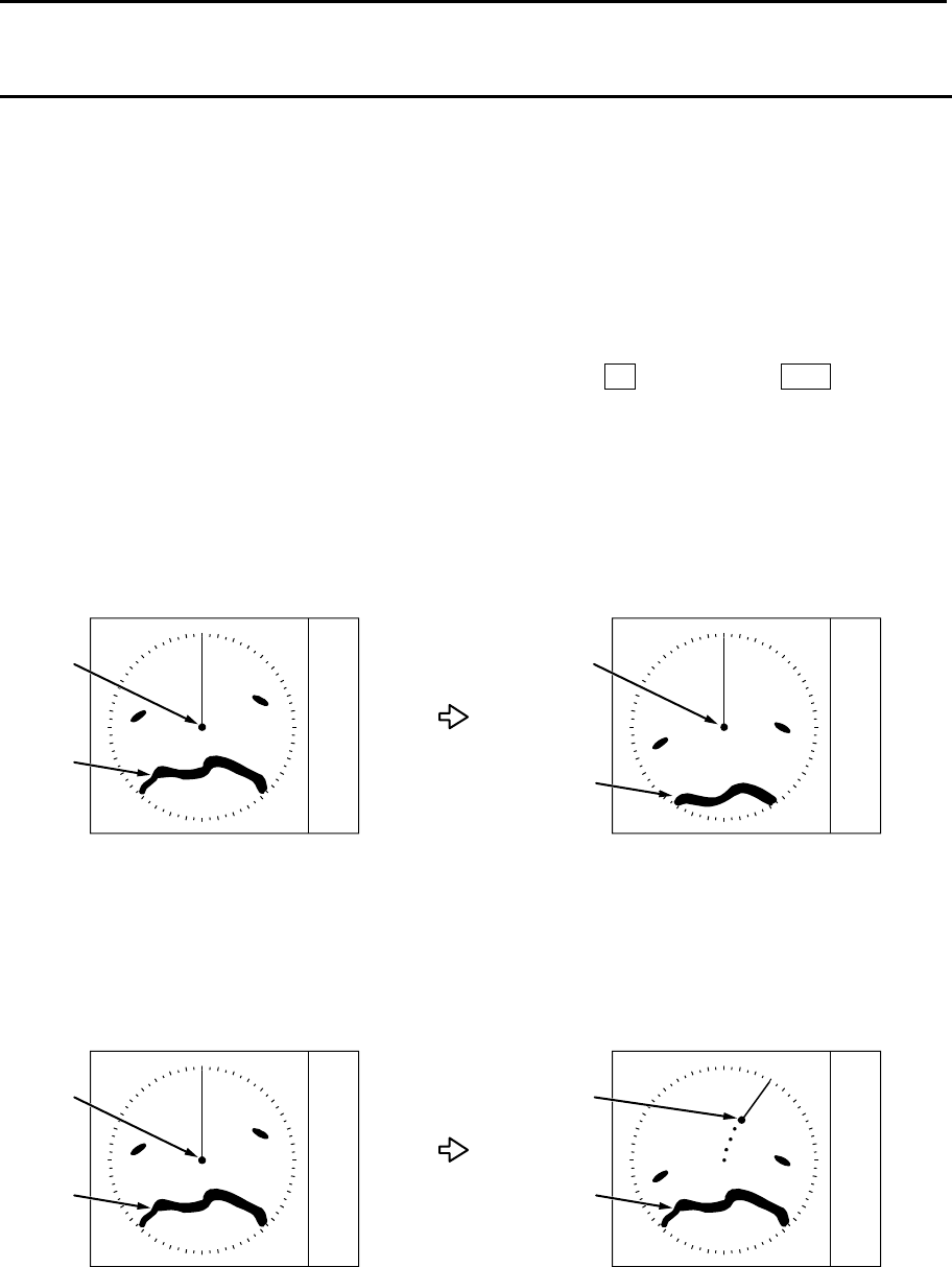
MDC-7000P/7900P Series Chapter 2 Radar Basic Operation
0093169006-05E 2-17
Moving
Land
Fixed
Moving
Antenna
position
Moving
Land Fixed
Moving
Antenna
position
For relative motion (RM) and true motion (TM)
Relative motion fixes your antenna position at the center of the display, and indicates the motion of
targets that surround your antenna position.
Your antenna position is displayed at the center. So, while the ship is moving, the fixed targets such as
the land also continue to move.
True motion indicates the motion of the target with respect to the specified bearing.
Fixed targets that do not move in any direction stay on the display, and all the moving targets move on
the display.
Note: The heading always continues to move. So, no true motion TM is available for H UP.
Relative motion (RM): The antenna position is fixed and the other surrounding targets move on the
display.
This is useful to monitor the surrounding situation with respect to own ship’s
position.
True motion (TM): The antenna position on the display moves according to its speed and tidal current.
Stationary targets are fixed on the display. This mode is useful to monitor your
position with respect to the fixed targets such as land.
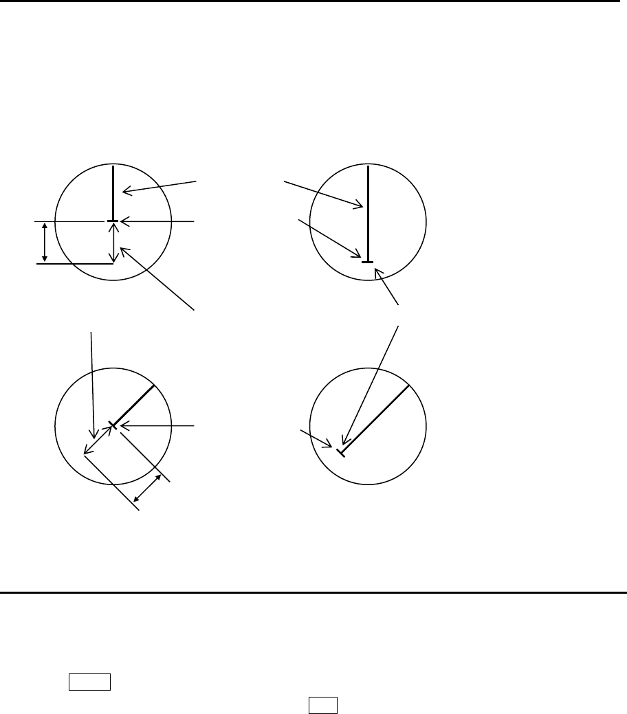
Chapter 2 Radar Basic Operation MDC-7000P/7900P Series
0093169006-05E 2-18
N-UP or C-UP TM mode is selected, own ship position moves to opposite side of heading direction,
and begins to show the true motion image. When own ship position reaches center of the range
scale, own ship position is to reset to the course over water or to the opposite direction of the
course over ground.
Reset true motion
Own ship display position can be manually reset when in true motion operation at any given point, by
following procedure.
1 Press MENU key to display “Menu”.
Select [DISPLAY] => [TM RESET], and press ENT key.
75%
Antenna position
75%
Antenna position
Antenna position direction and relocatable are in TM
Heading line
TM reset position
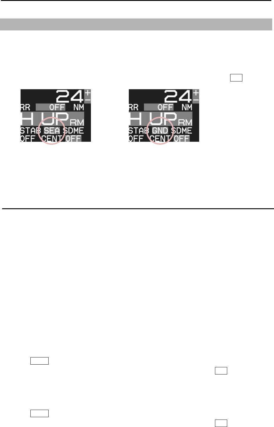
MDC-7000P/7900P Series Chapter 2 Radar Basic Operation
0093169006-05E 2-19
2.11 Ground and Sea stabilization
STAB MODE is a function to select speed for movement calculation for True trail, TT (ARPA), Past
position and True motion (TM).
SEA: Stabilization mode using speed over water.
GND: Stabilization mode using speed over ground.
[STAB MODE] can be changed directly at the upper left of the display, by cursor and ENT key.
When SDME or EPFS is not available for any reason, it is possible to get the speed over ground by
setting reference target.
Refer to 4.3 TT (ARPA) “Reference target acquisition”.
SEA (Sea stabilization)
SEA stabilization uses CTW (course through water) and STW (speed through water) referenced to
water. Accordingly course and speed indication at the upper right of the display becomes CTW/STW.
STW is relative speed of the ship against water surface in the heading direction.
Information from SDME (speed and distance measuring equipment) like LOG is inputted by serial
data (VBW or VHW).
Single axis water log indicated as LOG on the display cannot detect the effect of leeway.
When speed information is interrupted for 30 seconds from SDME for any reason or VBW water
status flag is invalid, then the numerical indication of CTW/STW becomes XXX.X in orange color.
In this case, speed can be entered manually.
Manual speed input.
By menu
Note: This menu is protected in normal. To cancel the protection, refer to 1.3 Menu usage “Display
[MAINTENANCE] menu”.
1 Press MENU key to display “Menu”.
Select [MAINTENANCE] => [I / O] => [STW] => [STW] => [MAN], and press ENT key.
2 Select [MAINTENANCE] => [I / O] => [STW] => [MAN] => input speed, and press ENT key.
By trackball
1 Press MENU key to display “Menu”.
Select [MAINTENANCE] => [I / O] => [STW] => [STW] => [MAN], and press ENT key.

Chapter 2 Radar Basic Operation MDC-7000P/7900P Series
0093169006-05E 2-20
2 Press MENU key to close menu.
3 Move cursor to the window on the right side of STW MAN on the top right side of the display.
4 Press ENT key to get ready for speed entry. Enter speed by using trackball.
5 Press ENT key to save the input.
GND (Ground stabilization)
GND stabilization uses COG (course over ground) and SOG (speed over ground) referenced to the
ground. Accordingly course and speed indication at the upper right side of the display becomes
COG/SOG.
SOG is the absolute speed of the ship with reference to the land.
Two-dimensional GND SDME device like dual axis LOG and EPFS (electronic position fixing
system) provide information for serial input.
If both serial sentence data of VTG (EPFS) and VBW (SDME) are available, then VBW takes
priority.
If failure of EPFS or SDME interrupts the speed information for 30 seconds or if the ground status
flag or VTG indicator flag is invalid, then the numerical indication of COG/SOG becomes XXXX in
orange color.
If SDME or EPFS is not usable due to failure or any other reason, then COG/SOG can be obtained
by setting Reference target.
Refer to 4.3 TT (ARPA) “Reference target acquisition”.
Note: IMO Resolution A.823 (19) ARPAs requires connection to water speed LOG.
In addition, VTG by EPFS or VBW by dual axis LOG should comply with requirements of IMO
Resolution MSC96 (72).
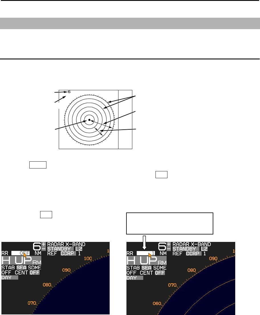
MDC-7000P/7900P Series Chapter 2 Radar Basic Operation
0093169006-05E 2-21
2.12 Measurement of distance by RR and VRM
There are three ways to measure distance to a target: Range Rings, Cursor or VRM.
Display Range Rings (RR)
Range rings (RR) are markers displayed at the specified distance from reference point.
They are used as a rough indication of the distance to a target.
1 Press MENU key to display “Menu”.
Select [NAV TOOL] => [RR] => [RR] => [ON], and press ENT key.
Note: [RR] display can be changed directly in the upper left of the display, by moving cursor and
pressing ENT key.
Note: When [NAV TOOL] => [BRG TRUE / REL] => [TRUE] is selected, 0° of the range rings indicates
North direction. While, when [REL] is selected it indicates heading direction.
RR on
“1” means range rings interval
RR 1 NM
Own
ship
Range
Ring separation
Range 6NM
Range rings
Ring separation 1NM
Range rings interval 1NM
Range rings interval
Reference point
Range rings
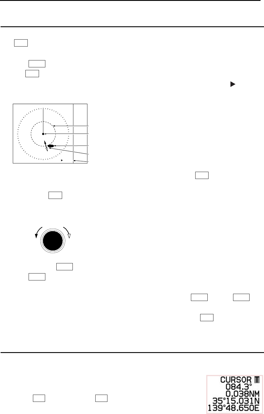
Chapter 2 Radar Basic Operation MDC-7000P/7900P Series
0093169006-05E 2-22
VRM1
3.290NM
8.990NM
VRM1
Target
Reference point
Distance to Target
Radius changed by VRM knob
Increase of
range
Decrease of
range
VRM knob
Measurement Range (VRM: Variable Range Marker)
Two variable range markers [VRM1] and [VRM2] are provided.
Turn VRM knob and lay each circle on the desired target to read the distance to the target on the
display.
1 Press VRM1 key to display a dashed line circle of VRM1.
Turn VRM knob to adjust the line circle on the desired target.
The distance to the target is indicated at the lower right of the display, and also a symbol is
displayed on the left side of the distance value.
2 The dashed line circle is zoomed in or zoomed out by turning VRM knob clockwise or
counterclockwise, respectively.
Note: Turning VRM knob (while pressing it) changes the range quickly.
3 Another press of VRM1 key will make the circle disappear.
4 Press VRM2 key to activate the dotted line circle of VRM2.
Operation procedure and distance display are the same as VRM1.
5 If you want to display both VRM1 and VRM2 simultaneously, press VRM1 key and VRM2 key.
Then, both the dashed line circle and the dotted line circle are displayed.
6 Switching between VRM1 and VRM2 is performed with pressing either of VRM keys as desired.
When the selected key is pressed, the color of operation panel changes to red.
Measurement Range (Cursor)
Move the cursor on the target with trackball.
The distance and bearing to the target is indicated at the lower right of the display.
Note: While “MENU” is displayed, the cursor operation cannot be used.
Press ENT key while pressing OFF key to return the cursor
to reference point position.
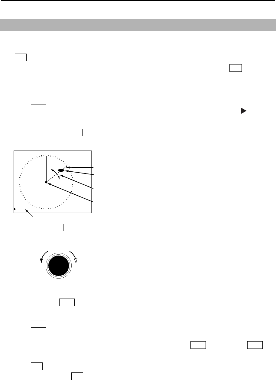
MDC-7000P/7900P Series Chapter 2 Radar Basic Operation
0093169006-05E 2-23
2.13 Measurement of bearing by EBL
This feature is used for measuring the bearing of the target from the base point (reference point for
default value.) Two electronic bearing lines [EBL1] and [EBL2] are provided.
Turn EBL knob and lay each bearing line on the desired target and read the bearing on the display.
[Bearing mode] can be changed directly in the lower left of the display, by cursor and ENT key, without
using menu function.
1 Press EBL1 key, and the bearing line of EBL1 is displayed as a dashed line.
The bearing value to the target is indicated at the lower left of the display, and a symbol is
displayed on the left side of the bearing value.
2 Rotate bearing line using EBL knob to adjust the line on the desired target.
The bearing value changes at the same time and you can read the bearing of the target.
Note: Turning EBL knob (while pressing it) changes the bearing quickly.
ClockwiseCounter
clockwise
EBL knob
3 Another press of EBL1 key, and the dashed line disappears and the bearing value on the lower left
of the display also disappears.
4 Press EBL2 key, and the bearing line is shown as a dotted line.
The operation procedure and display of the bearing is the same as EBL1.
5 If you want to display both EBL1 and EBL2 simultaneously, press EBL1 key and press EBL2 key.
Then, you can show both the dashed bearing line and the dotted bearing line.
6 Press EBL key to switch EBL1 or EBL2 as you desired.
The color of selected EBL key on the operating panel changes to red.
EBL1
060.5°
060.5°
EBL1
Target
Bearing cahnges
by turning EBL knob
Target bearing from own ship
Reference point
Bearing changes
by turning EBL knob
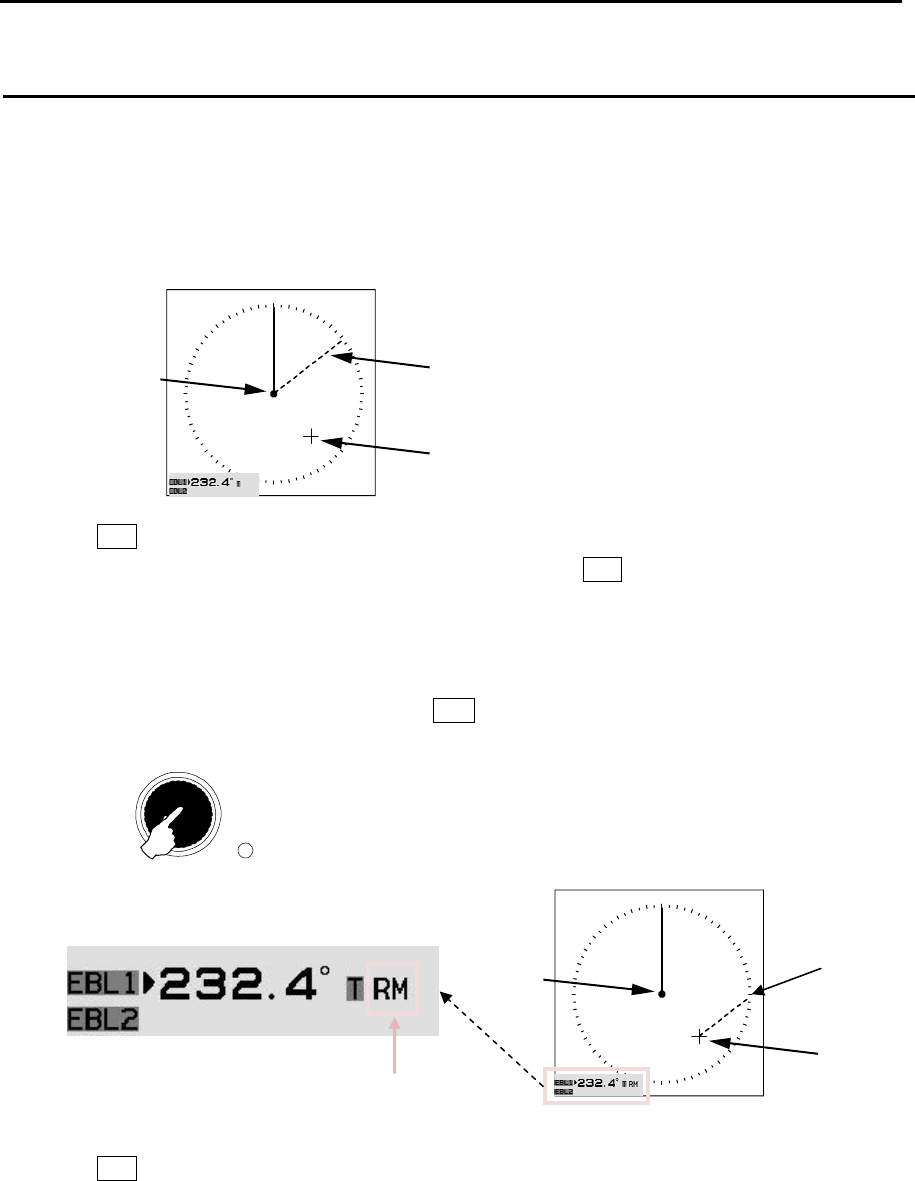
Chapter 2 Radar Basic Operation MDC-7000P/7900P Series
0093169006-05E 2-24
Using the EBL OFFSET
EBL base point can be changed to any position other than the initial reference point.
By changing the base point, the bearing from a random target can be measured.
1 Display the EBL for which the base point is required to be changed.
2 Move the cursor to new position.
3 Press EBL knob, and the base point of EBL changes.
During offset, the color of [OFFSET lamp] at the lower right of EBL knob changes from green to red,
and the “TM” or “RM” mark is added right of the numerical figures.
“TM” means true motion, and “RM” means relative motion of OFFSET EBL1 and EBL2.
The motion selection can be changed by [NAV TOOL] => [EBL] => [EBL1 OFFSET] or [EBL2
OFFSET] => select [RM] or [TM], and press ENT key.
4 Press EBL knob again, and the base point returns to the reference point.
Note: The base point for VRM cannot be changed.
Reference
point
EBL1
CURSOR
Push
EBL knob
Press OFFSET
OFFSET EBL true or relative motion mark
Reference
point
CURSOR
EBL1
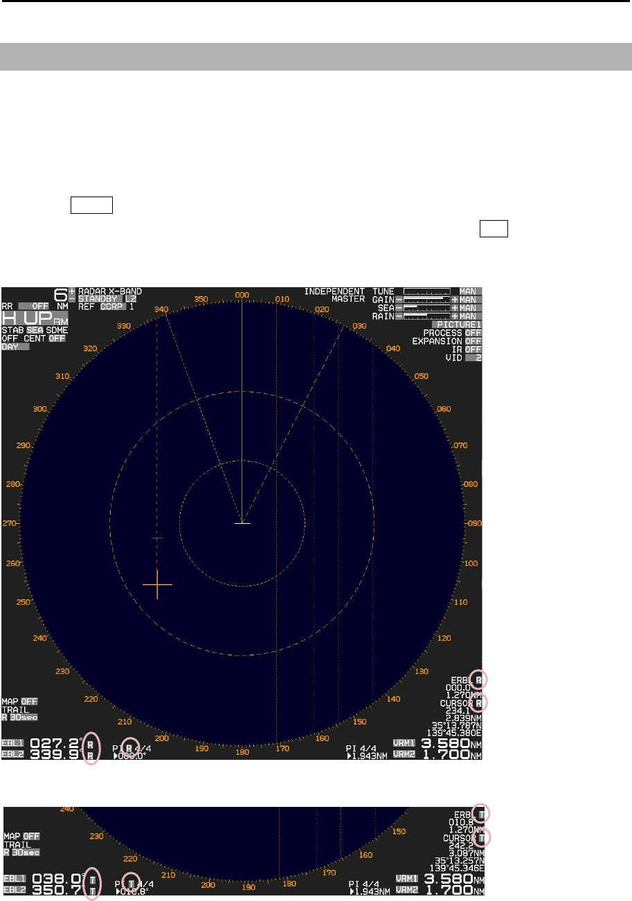
MDC-7000P/7900P Series Chapter 2 Radar Basic Operation
0093169006-05E 2-25
2.14 Bearing mode set up
This menu is used to change the bearing mode in EBL, PI, ERBL, Bearing scale and CURSOR.
The settings available in the true bearing with the true north of 000 degree, and in the relative bearing
with the heading of 000 degree.
1 Press MENU key to display “Menu”.
Select [NAV TOOL] => [BRG TRUE/REL] => [TRUE] or [REL], and press ENT key.
[EBL], [PI], [ERBL] and [CURSOR] can be changed directly on the display by using trackball.
Relative mode
True mode
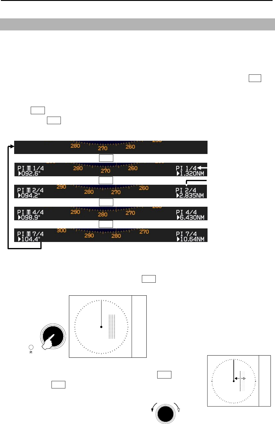
Chapter 2 Radar Basic Operation MDC-7000P/7900P Series
0093169006-05E 2-26
Increase of
range
Decrease of
range
VRM knob
PI 1/4
000.0° 3.000NM
PI RE L 1/4
2.15 Measurement of distance/bearing by PI
This function is used to display straight Parallel Index (PI) lines on one or both sides of the vessel,
range and bearing of which can be manipulated by following procedures.
Display location (distance, bearing) of each line can be changed independently or together when in
BULK operation. The length of LINE can also be changed.
[Bearing mode] can be changed directly in the lower left of the display, with trackball and ENT key,
without using menu function.
1 Press VRM knob, and PI lines are displayed.
By pressing VRM knob again, line number will be changed and will be turned off after the last line
selection.
2 While activated, the bearing and range are shown at the lower left and lower right of the display,
respectively.
The lamp color of PI located at the lower left of VRM knob changes from green to red when PI is
activated.
Push
V
RM knob
PI 1/4
000.0° 3.000NM
PI RE L 1/4
3 The range of selected line can be changed by turning VRM knob.
Note: Turning VRM knob (while pressing it) changes the range quickly.
Total number of lines
A
ctivated PI line number
1, 2, 4 and 7 lines are active in
this case.
Press VRM knob
Press VRM knob
Press VRM knob
Press VRM knob
Press
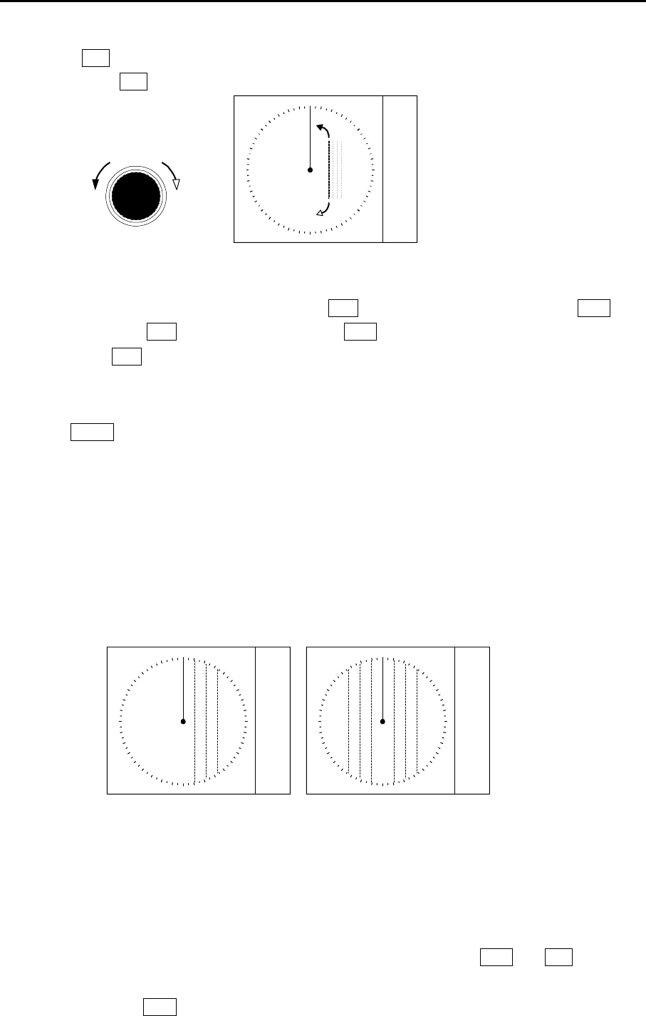
MDC-7000P/7900P Series Chapter 2 Radar Basic Operation
0093169006-05E 2-27
PI
000.0° 3.000NM
PI RE L PI
000.0° 3.000NM
PI RE L
HALF FULL
4 Turning EBL knob changes the bearing of a selected line.
Note: Turning EBL knob (while pressing it) changes the bearing quickly.
ClockwiseCounter
clockwise
EBL knob PI 1/4
000.0° 3.000NM
PI RE L 1/4
5 To return all PI lines to original position, press OFF key following by a quick press of VRM knob
while holding the OFF key. Make sure that the VRM knob press is followed immediately after
pressing the OFF key.
6 By following procedure user can turn any one of 7 lines ON or OFF and change its needed.
Press MENU key to display “Menu”.
Select [NAV TOOL] => [PI] => [LINE]
LINE => LINE: Lets user choose line number (1-7) and its parameters.
LINE => DISP: Lets user turn selected line ON or OFF.
LINE => START RNG: Lets user choose starting position of selected line.
(-96.0 – 96.0 NM)
LINE => END RNG: Lets user choose ending position of selected line.
(-96.0 – 96.0 NM)
PI DISP SIDE: Select HALF or FULL
MODE: Select CURSOR or LINE
CURSOR: If mode is set to CURSOR available selections are NORMAL, 1, 2, 3, 4, 5, 6 or 7
PI UNIT: Select NM, km or RANGE LINK
(RANGE LINK sets PI Units to same units used for range)
PI OPERATION: Select BULK or INDIVIDUAL
(When BULK is selected all PI lines are operated together by VRM and EBL knobs.)
(When INDIVIDUAL is selected PI lines are operated one by one in sequence by
pressing VRM knob)
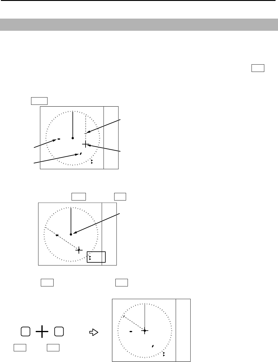
Chapter 2 Radar Basic Operation MDC-7000P/7900P Series
0093169006-05E 2-28
2.16 Measurement distance/bearing by ERBL
The given point of distance and bearing can be measured with the cursor as follows.
Measurement of distance and bearing from reference point can be performed by moving cursor to
reference point position.
[Bearing mode] can be changed directly in the lower right of the display, with trackball and ENT key,
without using menu function.
1 Press ERBL key and ERBL is displayed.
ERBL
000.0°
1.00NM
ERBL
REL
CURSOR
Target B
Target A
2 By moving cursor to target A, measurement of distance and bearing from target A to target B can
be obtained by using VRM knob and EBL knob.
ERBL
304.2°
2.82NM
REL
Own ship
3 Pressing ENT key (while pressing OFF key) returns cursor to the reference point position.
Therefore, it is possible to measure the distance/bearing from the reference point position.
ERBL
304.2°
2.82NM
REL
OFF
OFF key
ENT
ENT key
.
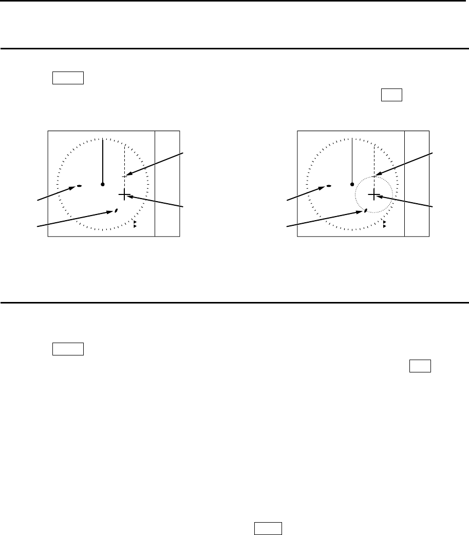
MDC-7000P/7900P Series Chapter 2 Radar Basic Operation
0093169006-05E 2-29
Change ERBL mark to LINE or RING
ERBL mark can be changed from LINE to RING.
1 Press MENU key to display “Menu”.
Select [NAV TOOL] => [ERBL] => [RNG] => select [LINE] or [RING], and press ENT key.
Change ERBL offset method
ERBL offset function can be operated by “CURSOR” or “TM”.
1 Press MENU key to display “Menu”.
Select [NAV TOOL] => [ERBL] => [OFFSET] => select [CURSOR] or [TM], and press ENT key.
[CURSOR]: The basic point of ERBL moves with the movement of the cursor.
[TM]: A cursor position becomes the basic point of ERBL.
After that, a position is fixed without synchronizing cursor movement.
The operation is limited to a bearing marker and range marker.
Note: [TM] function needs heading and Lat/Lon signal input of the own ship.
A basic point moves to the position of the last [TM] setting.
Move cursor in a new basic point, and press ERBL key.
ERBL
000.0°
1.00NM
ERBL
REL
CURSOR
Target B
Target A
ERBL
000.0°
1.00NM
ERBL
REL
CURSOR
Target B
Target A
(LINE) (RING)

Chapter 2 Radar Basic Operation MDC-7000P/7900P Series
0093169006-05E 2-30
2.17 Change color and brightness (Day/Night)
This function is used to change default echo, trail and all data color and contrast for day and night
mode.
DAY/NIGHT mode can be changed directly by pressing DAY/NIGHT key, or select DAY or NIGHT icon
at the upper left of the display by moving cursor and pressing ENT key.
Setup color
1 Select the mode (day or night) by pressing DAY/NIGHT key, color palette of which you would like
to change.
2 Press MENU key to display “Menu”.
Select [BRILL] => select [ECHO], [TRAIL], [BKGND PPI], [BKGND DATA], [DATA] or [OTHERS].
After selecting color for each item, press ENT key.
ECHO: YELLOW or GREEN
TRAIL: BLUE or BROWN
BKGND PPI: BLACK or BLUE
BKGND DATA: BLACK or BLUE
DATA: WHITE or GREY
OTHERS: CHART LAND:
BROWN, GREEN, LIME, YELLOW or GREY
DEPTH: WHITE, BLUE
3 Make sure day or night mode is selected by [BRILL] first before making adjustments in step 2.
Setup brightness
This is to set up brightness of ECHO, TRAIL, BKGND, OS TOOL, TGT, MAP, CURSOR, DATA,
WARNING and ALARM.
Default value of these items is 100 (max).
For safety reason, brightness cannot be adjusted to less than 20.
1 Select the mode (day or night) by pressing DAY/NIGHT key, brightness of which you would like to
change.
2 Press MENU key to display “Menu”.
Select [BRILL] => select [ECHO], [TRAIL], [BKGND], [OS TOOL], [TGT], [MAP], [CURSOR],
[DATA], [WARNING] or [ALARM]
After adjusting each item with trackball, press ENT key.
Color and brightness settings reset
If you want to return the color and brightness settings back to default value, please use following
procedure.
1 Press MENU key to display “Menu”.
Select [BRILL] => [RESET] => [GO], and press ENT key.
MDC-7000P/7900P Series Chapter 2 Radar Basic Operation
0093169006-05E 2-31
TRUE/REL REL
TIME TRUE
SHAPE
TRAIL LEVEL
CLEAR >
RANGE KEEP
2.18 Remove the heading line/navigation data
This function is used when a target is overlapped with a heading line and hard to be distinguished.
1 Press OFF key to temporarily hide the heading line.
For safety reason, the heading line disappears only while the key is pressed. (It is not possible to
keep it removed.)
Continue pressing OFF key for 2sec. All navigation tool data (RR, EBL, VRM, ERBL, PI, [MAP],
such as COAST LINE, NAV LINE, ROUTE, EVENT MKR, and AREA, etc.) will hide.
2.19 Target trail
Other ships trails are displayed by following procedures.
Two display modes, relative display REL and true display TRUE are available.
At the start of trail, “TRAIL” characters at lower left of the display change to yellow. When trail time has
passed, character color turns white.
Note:
• The trail by its nature records and displays past images. The trail does not display right after
transmission is started.
In addition, after the change of [TIME], or after the change of two or more steps in [RANGE], the trail
will disappear, because the recording is reset (erased).
• The trail [TIME] and [REL] or [TRUE] mode can be changed directly at the lower left of the display,
with trackball and ENT key, without using menu function.
1 Press MENU key to display “Menu”.
Select [TRAIL] => [TRUE / REL], and press ENT after making selection.
2 There are additional set up items, [TIME], [SHAPE], [TRAIL LEVEL], [CLEAR] and [RANGE KEEP].
[TIME]: This is to set up the time of the trail to be displayed.
Initial set up time: OFF, 30sec, 1min, 3min, 6min, 12min, 30min, 60min, PERM
Time setting can be changed by [STARTUP] => [TIME] menu operation.

Chapter 2 Radar Basic Operation MDC-7000P/7900P Series
0093169006-05E 2-32
[SHAPE]: Seven types of trail shapes available, as shown below.
[TRAIL LEVEL]: This is to set up echo level of trail to be recorded.
“1” records all signal levels returned as a trail, “15” records only the strongest
signal levels as a trail.
[CLEAR]: Is to delete all current trails and restart new trails.
[RANGE KEEP]: “OFF” deletes trails when changing range,
“ON” does not delete trails when changing range.
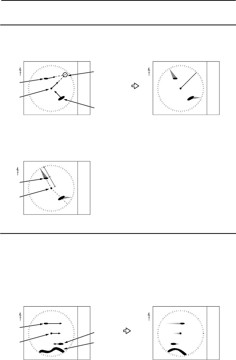
MDC-7000P/7900P Series Chapter 2 Radar Basic Operation
0093169006-05E 2-33
Relative display (R)
The target trail is displayed as result of sum of vector (course and speed) of the target ship and your
ship. When your ship is on the projected course of this trail, it shows that a collision may occur in future.
This display is useful to help detect a dangerous situation.
NN
<Display mode[N UP RM] >
Target 1
Course and speed of a real ship Ships relative trails
Target 2
Two ships on a
collision course
Antenna
position
TRAIL
REL
TRAIL
REL
Target 1, whose trail is overlapping the EBL, is a dangerous target while the Target 2 is not. If trail
setting is six minutes, and if the trail length is equal to the distance between the antenna position and
Target 1, then the collision will occur after six minutes.
N
<Display mode[N UP RM] >
Target 1
6min
6min
Prospect of collision after 6min
Antenna
position
TRAIL
REL
True display (T)
This mode displays the trail of the moving target over a specified time interval independently from own
ship's movement.
This mode is used to monitor the bearing and speed of the target.
No trails of fixed targets such as land are shown using this display.
The amount of movement of all ships, own ship, Target 1 and Target 2 are drawn as trails.
The land does not move, so its trail is not shown.
NN
<Display mode[N UP RM] >
Target 1
Course and speed of a real ship Trail after the time has passed
Target 2
Time passes
Land
Antenna
position
TRAIL
T
TRAIL
T
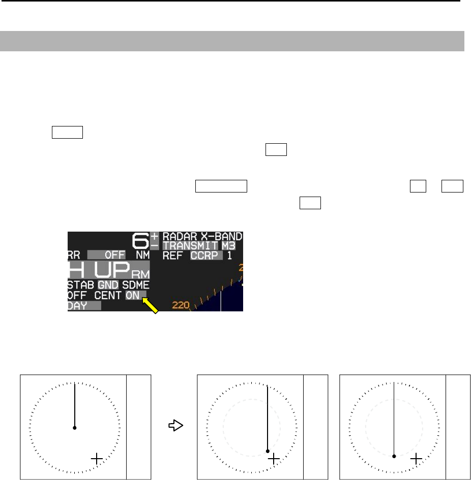
Chapter 2 Radar Basic Operation MDC-7000P/7900P Series
0093169006-05E 2-34
2.20 Off Center
This function is used to get larger view in heading direction.
Two ways “OFF CENTER” can be setup.
[CURSOR]: Off-centering to CURSOR direction.
[OPPOSITE]: Off-centering to the stern direction.
1 Press MENU key to display “Menu”.
Select [DISPLAY] => [OFF CENT POINT] and press ENT key after selecting the off center point
“CURSOR” or “OPPOSITE”.
2 Off-centering is executed by pressing OFF CENT key, or move cursor to set value of ON or OFF
of [OFF CENT] at the upper left part of the display, and press ENT key.
3 The difference of [CURSOR] and [OPPOSITE] are as follows.
CURSOR OPPOSITE
Note: When CCRP is selected for the reference positon, there is possibility that CCRP is located
outside of 90 % echo image area at OFF CENTER function in short range.
In this case, alarm message of “Cannot use the CCRP” will appear at lower right of the display,
and the reference position is automatically changed to ANT position.
Refer to 2.34 Reference position and Display center.
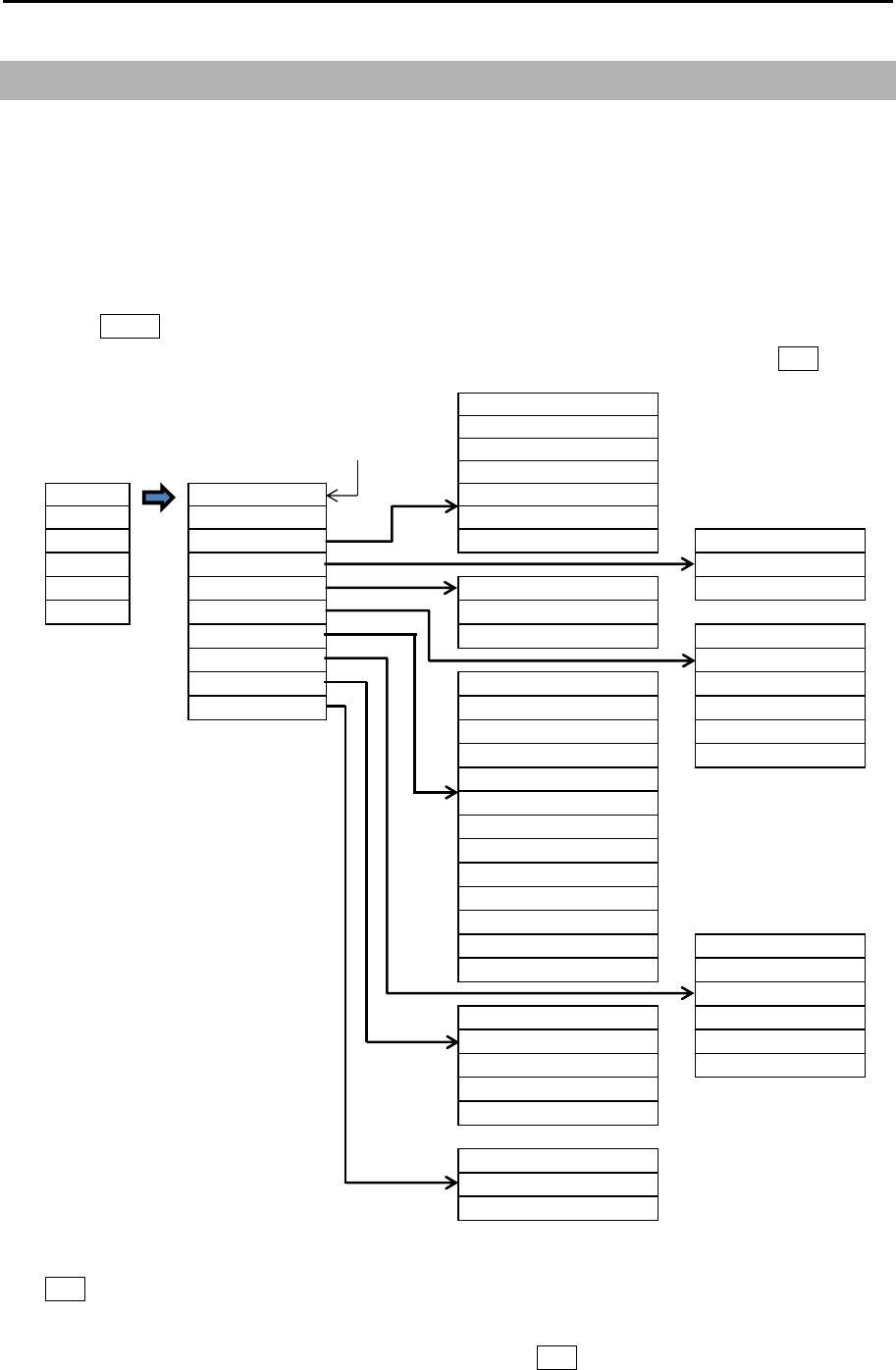
MDC-7000P/7900P Series Chapter 2 Radar Basic Operation
0093169006-05E 2-35
2.21 Function key usage
For quick function access, there are six dedicated function keys provided on this radar (“F1”, “F2”, “F3”,
“F4”, “F5” and “F6”).
You can switch to a pre-specified function by pressing each key.
Note: This menu is protected in normal. To cancel the protection, refer to 1.3 Menu usage “Display
[MAINTENANCE] menu”.
1 Press MENU key to display “Menu”.
Select [MAINTENANCE] => [STARTUP] => [FUNCTION KEY] => [F1] key => press ENT key and
after selecting the setup value.
2 Follow procedure (1) to setup keys [F2], [F3], [F4], [F5] and [F6] by selecting each item and press
ENT key.
3 Another way to setup each function key is to press and hold desired key until menu selection
shows up on the right of display. Using trackball and ENT key make a selection and save to
designated function key.
PICTURE MODE
PROCESS
Dedicated function name
EXPANSION
IR
F1 > VID
F2 > OFF NOISE REJ
F3 > ECHO > SART TRAIL T/REL
F4 > TRAIL > TRAIL TIME
F5 > DISPLAY > STAB TRAIL RESET
F6 > ALARM > TM RESET
TARGET > C UP RESET ECHO ALARM
NAV TOOL > ECHO ALARM EDIT
MAP > VECT T/REL MAP AREA ALARM
SYSTEM > VECT TIME GUARD ZONE
CPA/TCPA GUARD ZONE EDIT
PAST POSN T/REL NAV LINE CROSS
PAST POSN TIME
AUTO ACQ AREA
AUTO ACQ AREA EDIT
OS PAST TRK RESET
AIS
TT DELETE
TT ALL DELETE
ACQ RR
TT REF ACQ BRG T/REL
GUARD LINE
OWN TRACK SHIP OUTLINE
TARGET TRACK STERN LINE
MAP DISP BARGE ICON
EVENT CURSOR
EVENT OWN
TIME
ASSISTANT DISP
TGT LIST S ORT
VECT TIME
STAB MODE
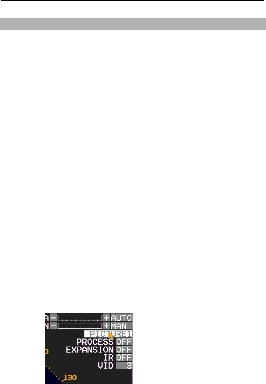
Chapter 2 Radar Basic Operation MDC-7000P/7900P Series
0093169006-05E 2-36
2.22 Set picture mode
It is necessary to make adjustment to the radar picture as environment and sea condition changes. The
Picture mode can quickly change for different settings, [PROCESS], [EXPANSION], [IR] and [VID],
depending on the situation. You can change these setting items individually, and these changes are
stored in internal memory.
1 Press MENU key to display “Menu”.
Select [ECHO] => [PICTURE MODE] => press ENT key after making your selection.
The setting value can be selected from “PICTURE1, PICTURE2, PICTURE3, NEAR, FAR,
HARBOR, ROUGH SEA, RAIN or PURE”.
PROCESS EXPANSION IR VID
PICTURE1: OFF OFF 1 3
PICTURE2: C2 2 OFF 2
PICTURE3: C2 1 OFF 1
NEAR: OFF OFF 1 1
FAR: C1 2 OFF 4
HARBOR: C1 1 2 1
ROUGH SEA: C2 OFF 1 1
RAIN: C1 OFF 1 1
PURE: OFF OFF OFF 1
PROCESS: Refer to 2.23 Echo process.
EXPANSION: Refer to 2.24 Echo expansion.
IR: Refer to 2.25 Interference rejection (IR).
VID: Refer to 2.26 Video contrast.
[PICTURE MODE] can be changed directly at the upper right of the display using trackball.
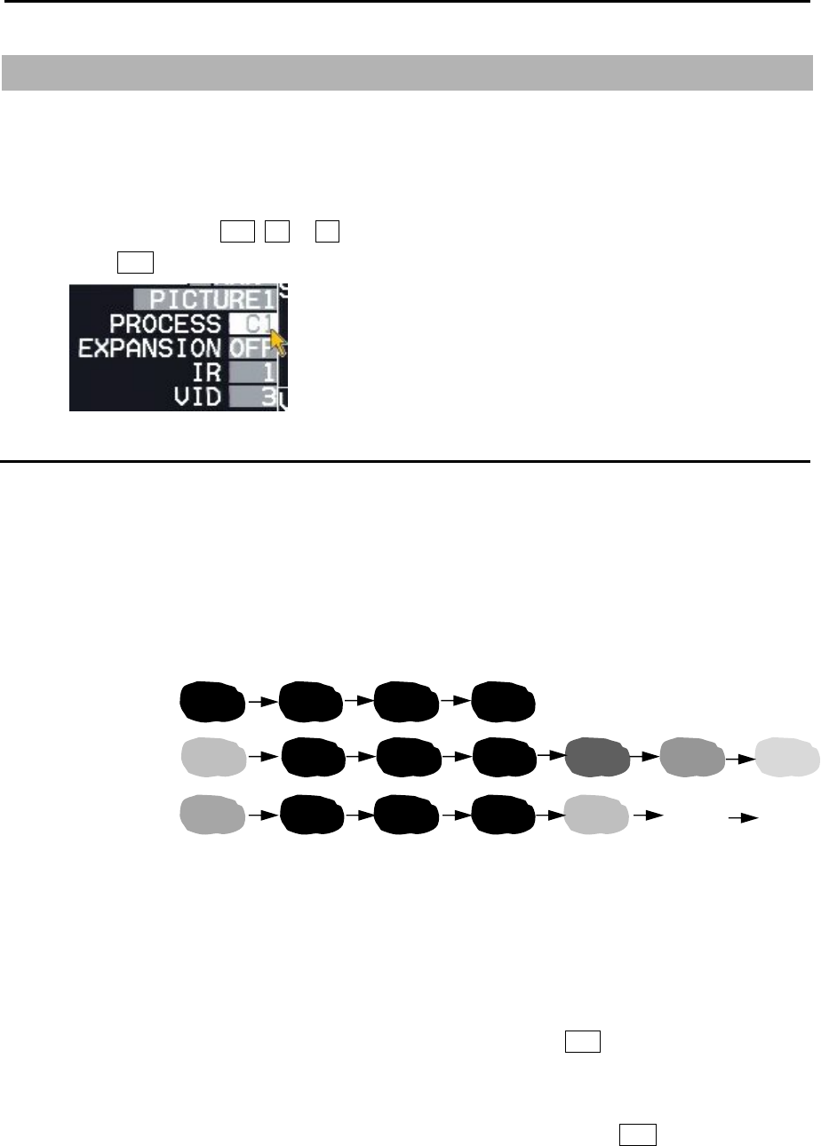
MDC-7000P/7900P Series Chapter 2 Radar Basic Operation
0093169006-05E 2-37
2.23 Echo process
Echo process mode feature reduce sea clutter effectively. Echo process mode is used correlation
method. Two types of C1 and C2 are available.
[PROCESS] mode can be changed directly at the upper right of the display using trackball.
1 Move the cursor to OFF, C1 or C2 of [PROCESS] at the upper right part of the display.
Press ENT key repeatedly until the desired choice appears.
Correlation image echo process
At setup value of C1 or C2, correlation images are averaged.
When there is a stable image such as a ship among sporadic images such as sea clutter, the sea
clutter is reduced by averaging to leave the stable image.
Due to the averaging process, even though stable strong images appeared just after transmission, they
are displayed weaker and gradually turn into strong images.
Note:
• For confirmation of an image that may be hidden between the waves and the image of a fast ship that
appears at a different position for each scan, the image may be displayed weaker than the actual one.
Therefore, when fast moving target on the display, select [PROCESS] OFF.
• For operation of GAIN, SEA and RAIN, it may take some time before it becomes effective. Take
enough time for the operation, or operate again after [PROCESS] has been once off.
• Echo process mode requires heading signal, echo process mode turns into OFF if heading signal is
unavailable.
PROCESS: OFF
PROCESS: C1
PROCESS: C2
Scan1 Scan2 Scan3 Scan4 Scan5 Scan6 Scan7
Display of correlaion image process in the case when an image appeared and disappeared.
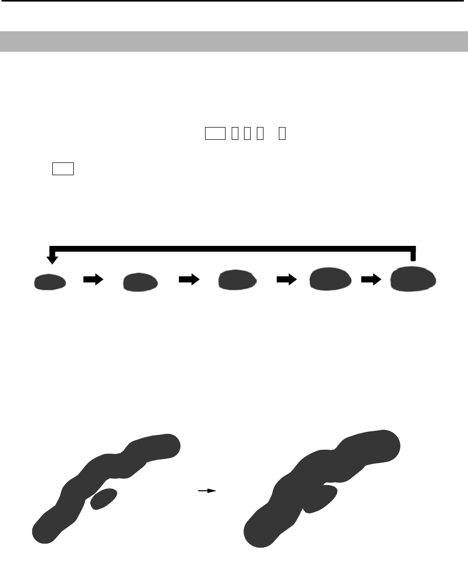
Chapter 2 Radar Basic Operation MDC-7000P/7900P Series
0093169006-05E 2-38
EXP:OFF EXP:2
EXP:1 EXP:3 EXP:4
2.24 Echo expansion
This function is to enlarge an image in the direction of distance/bearing.
Small ships and remote targets can be enlarged to be easier to see.
[EXPANSION] can be changed directly at the upper right of the display.
1 Move the cursor to set value window of OFF, 1, 2, 3 or 4 of [EXPANSION] at the upper right part
of the display.
Press ENT key repeatedly until the desired choice appears.
Note: The setting value can be selected from “OFF, 1, 2, 3 and 4” and the larger value applies stronger
enhance effect.
Note: The enlargement of targets has effect on all echoes. So, a large target such as land is also
enlarged. Consequently, land and a small target may sometimes be seen as a single target. Pay
attention to that.
ENH: OFF ENH: 3
EXPANSION : OFF EXPANSION: 4

MDC-7000P/7900P Series Chapter 2 Radar Basic Operation
0093169006-05E 2-39
2.25 Interference rejection (IR)
This feature is used to reject interference from other radars.
Radar transmissions on same frequency band can cause interference noise on the display depending
on its transmitted power. This noise pattern appearance varies case by case, but is usually spiral shape
or like the spokes of a wheel in shape. This function can reduce interference effect.
[IR] can be changed directly at the upper right of the display.
[IR] is also effective to reduce second echo phenomenon.
1 Move the cursor to set value window of [IR] at the upper right part of the display.
Press ENT key repeatedly until desired value appears.
Note:
• The setting value can be selected from “OFF, 1, 2, and 3” and the larger value applies stronger
interference rejection effect.
• Too much removal effect may also remove small targets. Pay attention to that.
2.26 Video contrast
This is a function to change the relation between the strength of returned echo and their display
gradation.
At VID 1, the difference of signals strength between strong echo and weak echo becomes larger. As
the numerical figure becomes larger in VID 2, VID 3, VID 4, and VID 5 the difference in signal strength
becomes smaller.
[VID] can be changed directly at the upper right of the display.
1 Move cursor to 1, 2, 3, 4 or 5 of [VID] at the upper right part of the display.
Press ENT key repeatedly until desired value appears.
When the difference of signal strength is small, images becomes sharper.
However, signal strength from small ships and buoys is weak, and the difference between clutter and
them is not large enough.
Therefore, it is necessary to display clutter which may blend together with small ships and buoys.
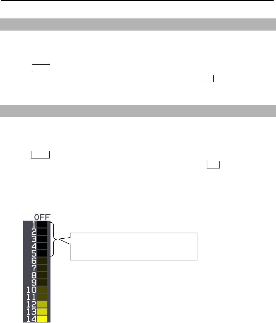
Chapter 2 Radar Basic Operation MDC-7000P/7900P Series
0093169006-05E 2-40
2.27 Noise rejection
This radar is equipped with a function that is capable to remove various signals picked up by the radar
such as white noise, and display clean picture.
1 Press MENU key to display “Menu”.
Select [ECHO] => [NOISE REJ] => select [OFF], [1] or [2], and press ENT key.
2.28 Echo color rejection
This radar has a function to remove a color selected by menu operation.
This effect is to show the strong signal image clearly and to delete the unwanted signal such as noise.
1 Press MENU key to display “Menu”.
Select [ECHO] => [COLOR REJ] => select [OFF] or [1 to 14], and press ENT key.
Selection value 1: Lowest signal level color
Selection value 14: Highest signal level color
If set at 5, echo colors from 1 to 5 will not be
displayed.
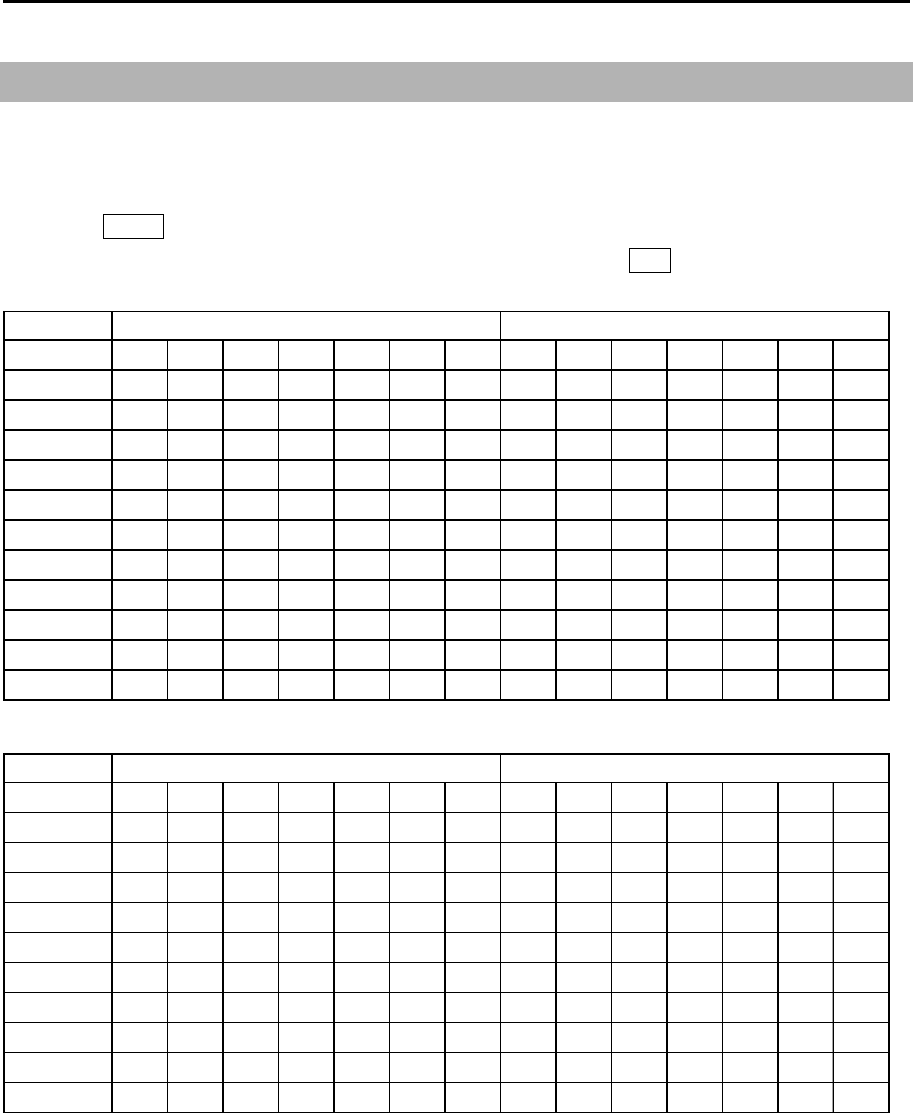
MDC-7000P/7900P Series Chapter 2 Radar Basic Operation
0093169006-05E 2-41
2.29 Pulse width
This radar can change pulse width of the transmission from 0.5NM to 12NM range scale.
SP and LP pulse width can be set separately.
1 Press MENU key to display “Menu”.
Select [ECHO] => [PULSE WIDTH] => set pulse width, and press ENT key.
12kW
Range
0.125 S1 S1
0.25 S1 S1
0.5 S1 S2 S1 S2
0.75 S1 S2 S1 S2
1.5 S1 S2 M1 M2 S1 S2 M1 M2
3S2
M1 M2 M3 L1 S2 M1 M2 M3 L1
6M2
M3 L1 L2 M2 M3 L1 L2
12 L1 L2 L1 L2
24 L2 L2
32 L2 L2
48 L2 L2
64 L3 L3
25kW
Range
0.125 S1 S1
0.25 S1 S1
0.5 S1 S2 S1 S2
0.75 S1 S2 S1 S2
1.5 S1 S2 M1 M2 S1 S2 M1 M2
3S2
M1 M2 M3 L1 S2 M1 M2 M3 L1
6M2
M3 L1 L2 M2 M3 L1 L2
12 L1 L2 L1 L2
24 L2 L2
48 L2 L2
96 L3 L3
SP mode LP mode
SP mode LP mode

Chapter 2 Radar Basic Operation MDC-7000P/7900P Series
0093169006-05E 2-42
2.30 Receiving Radar Beacons, SART and Radar Enhancer
The X-band radar system is required to be capable of receiving signals emitted from a Radar Beacon,
SART (Search and Rescue Transponder) and Radar enhancer. To receive those signals by the radar
system, use the following procedures.
1 Press MENU key to display “Menu”.
Select [ECHO] => [SART] => [ON], and press ENT key.
2 Radar functions are set with following settings.
Range scale: 12 NM
Pulse width: L2
PROCESS: OFF
Interference Rejection: OFF
Performance Monitor: OFF
3 In case the radar picture is obscured with too many signals, reduce gain for better observation.
4 When own ship approaches the transmitting Radar Beacon or SART, the echoes will become
blurred in an arc. For better observation of those signals, adjust the Gain, SEA and RAIN controls,
as appropriate.
5 [ECHO] => [SART] => [OFF], and press ENT key, the setting of above 3 is restored.
About SART
According to the GMDSS (Global Maritime Distress and Safety Systems) requirement, the IMO/SOLAS
class ships must be equipped with a SART. When a ship is in distress, a signal will be automatically
emitted from the SART so that other ships and/or aircrafts can identify its location. When your ship
equipped with a X-band radar comes within 8 NM of a ship in distress, the SART picks up the radar
signal and responds to it. The signal consists of 12 sweeps and is emitted in the frequency range of 9.2
GHz through to 9.5 GHz. The SART has two sweep times that switch from slow sweep (7.5μs) to fast
sweep (0.4μs) and vice versa, according to the distance. When the radar receives this signal, a line of
12 dots, which is equally spaced at about 0.64 NM, appears on the display. The nearest blip of the
SART indicates the location of the ship in distress. When your ship comes within 1 NM to the SART, a
fast sweep signal is displayed on the radar and a thin line connects the 12 blips.
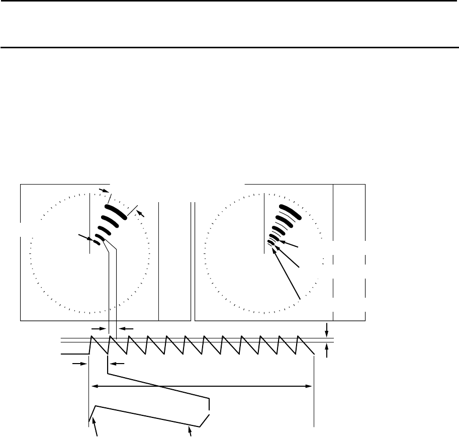
MDC-7000P/7900P Series Chapter 2 Radar Basic Operation
0093169006-05E 2-43
Actual location of the ship carrying the SART
If your ship is located at 1 NM or more away from the SART, the position at which the first echo is
displayed is 0.64 NM behind the actual SART position when the 12 SART echoes are identified. If your
ship comes within 1 NM from the SART, the fast sweep signal is indicated. The position of this echo is
displayed 150 m beyond the actual SART position.
Slow sweep signal
Fast sweep signal
Beam width of the
radar signal received
SART position
SART position
1 nm or more beyond
the SART position
Within 1 nm of S
A
RT position
9.5GHz
9.2GHz
7.5µs sweep time
95µs sweep time
Slow sweep signalFast sweep signal
Sweep start
The SART signal presentation and its signal timing
1 NM or more beyond Within 1 NM o
f
S
ART position
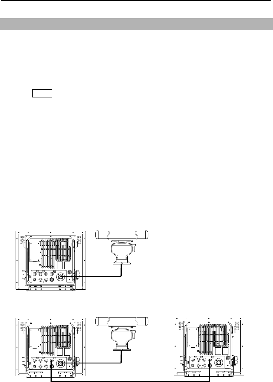
Chapter 2 Radar Basic Operation MDC-7000P/7900P Series
0093169006-05E 2-44
INDEPENDENT MASTER
INDEPENDENT MASTER Remote cable INDEPENDENT SLAVE
CW-561-**M
2.31 Inter-switch
Inter-switch is a way to setup two radars to be connected together
Note: If either radar fails while two radars are in use, then set the [INTER-SWITCH] menu of the
working radar to [INDEPENDENT MASTER] and use it independently.
Note: [INTER-SWITCH] menu cannot be used while transmitting.
1 Press MENU key to display “Menu”.
Select [SYSTEM] => [INTER-SWITCH] => select [INTER-SWITCH] mode*, and press
ENT key.
* Available choices: INDEPENDENT MASTER, INDEPENDENT SLAVE, DUAL MASTER,
DUAL SLAVE, CROSS, MONITOR
INDEPENDENT MASTER: Connection status where one antenna is connected to one radar.
INDEPENDENT SLAVE: Connection status where the dedicated cable is connected to the above
-mentioned INDEPENDENT (MASTER), and the image of antenna of
INDEPENDENT (MASTER) is displayed.
The antenna cannot be controlled. So, it is impossible to perform the change
etc. of pulse width.
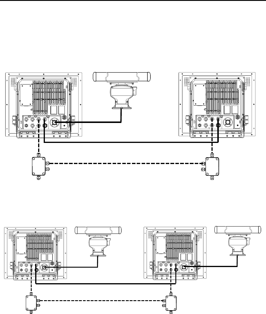
MDC-7000P/7900P Series Chapter 2 Radar Basic Operation
0093169006-05E 2-45
SD05-1973
DUAL MASTER DUAL SLAVE
SD05-1973
CROSS
DUAL MASTER: Connection topology is the same as the above-mentioned INDEPENDENT
(MASTER) and INDEPENDENT (SLAVE). By this way, either radar can control the
antenna. The radar to which the antenna is connected is DUAL (MASTER).
DUAL SLAVE: The radar to which the antenna is not connected is DUAL (SLAVE).
CROSS: In this status, there are two radars to which each antenna is connected. In this status, the
antenna that is not connected to its own radar is used.
MONITOR: In this status, the antenna is not connected, and a simulator is connected and used.
Note: When you use inter-switch mode at first time, please set Heading (HL OFFSET), TX DELAY and
ANT CABLE adjustment of each antenna. (Refer to 4.2.2, 4.2.3 and 4.2.4 of Installation manual)
These setting data are memorized in non-volatile memory, and applied automatically when each
antenna is selected.
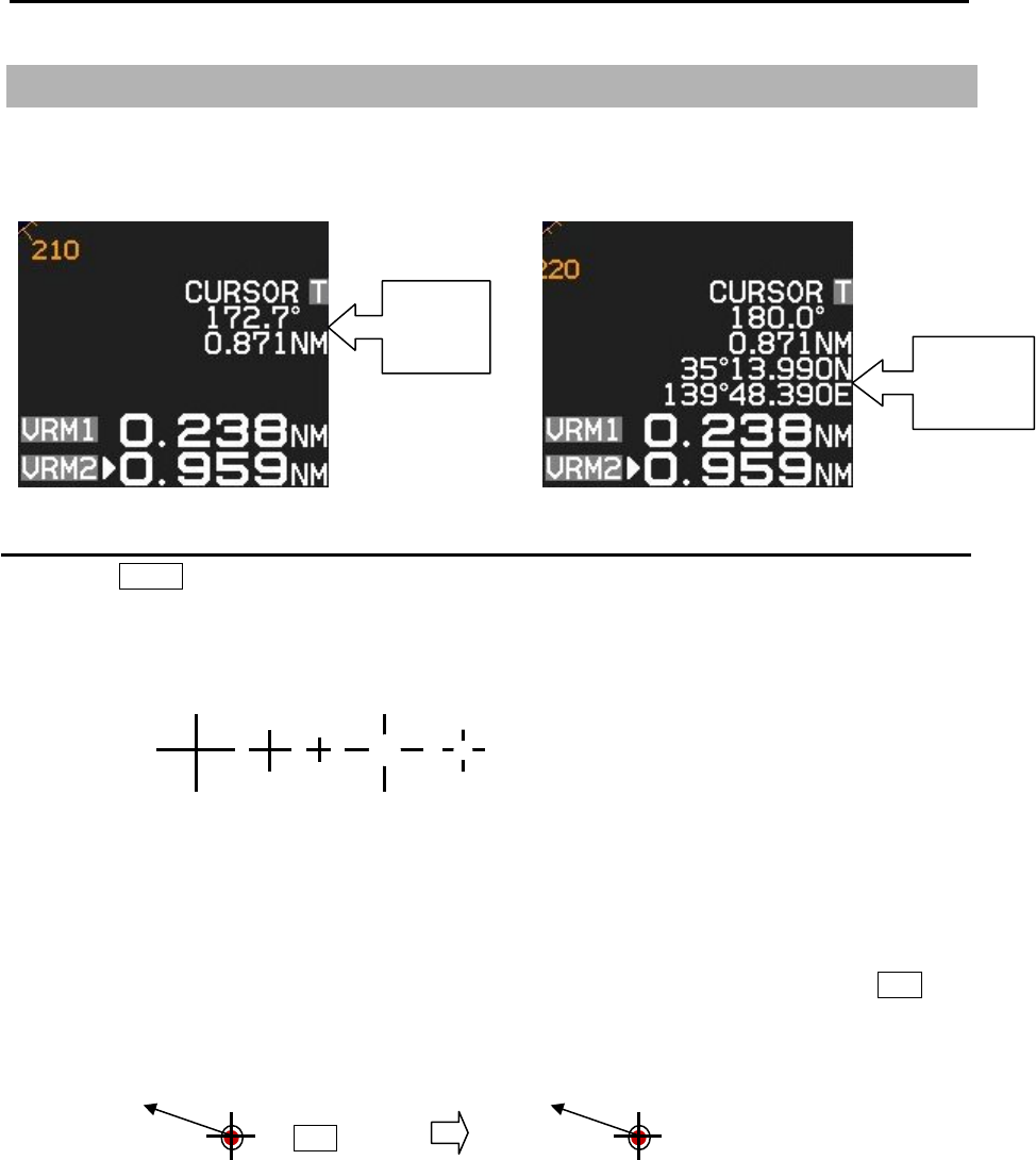
Chapter 2 Radar Basic Operation MDC-7000P/7900P Series
0093169006-05E 2-46
2.32 Cursor data
Cursor data is displayed in distance and bearing at lower right of the display. In addition, it can also be
displayed in latitude and longitude position.
CURSOR setting menu
1 Press MENU key to display “Menu”.
select [NAV TOOL] => [CURSOR] =>
CURSOR SHAPE: Set up shape of cursor.
CURSOR: ON/OFF of the cursor indication.
LAT/LON: ON/OFF of the latitude and longitude position display.
CURSOR HUP MOVE: When HUP mode is used, OFF always remains at the fixed position.
ON links a bearing changes and moves.
INFO: ON/OFF of the TT, AIS and MAP information data display selected by cursor and ENT key.
ON: TT, AIS and MAP information data will be displayed near cursor during about 15 sec.
after these data is selected.
Bearing
Distance Latitude
Longitude
ENT key TT - xx
312.5o
8.3kn

MDC-7000P/7900P Series Chapter 2 Radar Basic Operation
0093169006-05E 2-47
2.33 Performance monitor
Performance monitor is a function to confirm performance degradation such as aging phenomena etc.,
by recording performance of antenna on its installation or on exchange of antenna parts.
Note: Carry out initial setup without failure on its installation or on exchange of antenna parts.
Confirmation method for degradation of Antenna performance after operation
1 Press MENU key to display “Menu”.
Select [SYSTEM] => [MON] => [ON], and press ENT key.
Range is changed to 24NM automatically.
2 Confirm SYSTEM bar value.
Please contact with our sales agent or our sales department when SYSTEM bar becomes a half
(–10dB) or less in length, because there is a possibility of large performance degradation.
When contacting, please let person in charge know about degradation rate of TX and RX bars.
3 Select [SYSTEM] => [MON] => [OFF], and press ENT key.
Initial setup methods: Refer to Installation manual.
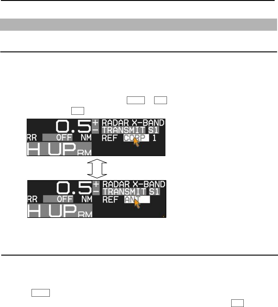
Chapter 2 Radar Basic Operation MDC-7000P/7900P Series
0093169006-05E 2-48
2.34 Reference position and Display center
Reference position
The base point for range, bearing, relative course, relative speed, CPA or TCPA, EBL or VRM is named
[Reference position], respectively.
Either CCRP (consistent common reference point) or ANT (antenna position) can be used as the
reference position.
Selection of the reference position is made in CCRP or ANT of [REF] located of the upper left of the
display, with trackball and ENT key.
Display center
The display center positon can be changed to CCRP (consistent common reference point) or ANT
(antenna position) when reference position is CCRP.
1 Press MENU key to display “Menu”.
Select [DISPLAY] => [DISPLAY CENTER] => select [ANT] or [CCRP], and press ENT key.
The display center of echo image (PPI) is always ANT position.
When CCRP is selected for the reference position, there is possibility that CCRP is located outside of
90 % echo image area in short distance range.
In this case, the reference position is automatically changed to ANT position.
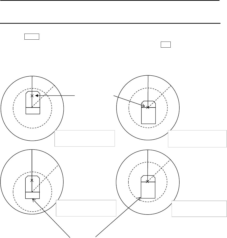
MDC-7000P/7900P Series Chapter 2 Radar Basic Operation
0093169006-05E 2-49
Ref. position: CCRP
Display center: CCRP Ref. position: ANT
Display center: CCRP
Ref. position: ANT
Display center: ANT
Ref. position: CCRP
Display center: ANT
Antenna
position mark
Ship
outline
(Refer to 2.35 Setup
own ship outline.)
Antenna position mark ON or OFF
1 Press MENU key to display “Menu”.
Select [DISPLAY] => [ANT POSN] => select [ON] or [OFF], and press ENT key.
Note: Antenna position mark is displayed at transmission on condition.
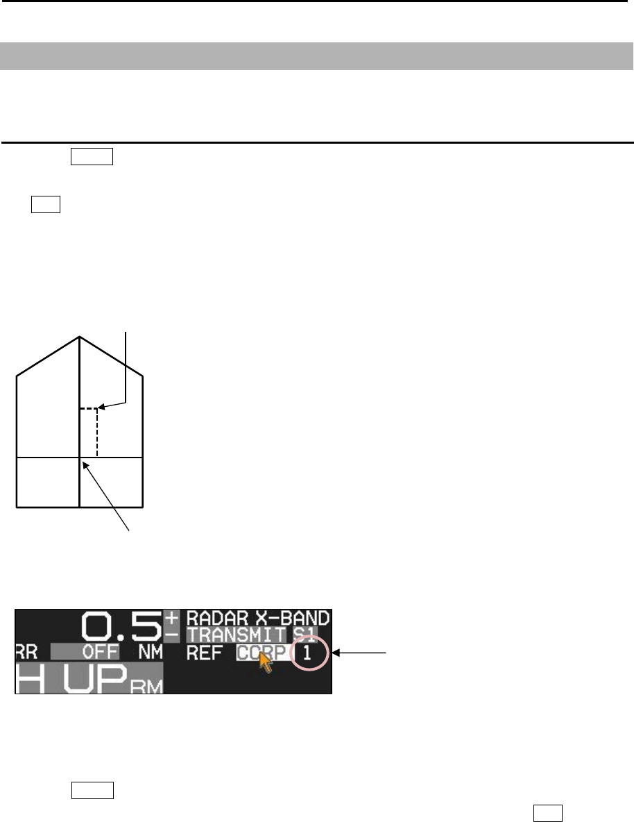
Chapter 2 Radar Basic Operation MDC-7000P/7900P Series
0093169006-05E 2-50
A
B
CD
dx
dy
OUTLINE
A 0 −511m
B 0 −511m
C 0 −63m
D 0 −63m
ANT OFFSET
dx -63 −63m
dy -511 − 511m
CCRP
p
osition
ANT
position
2.35 Setup own ship outline
Set up own ship outline and antenna position from CCRP (Consistent common reference point).
Setup CCRP number and ship outline
1 Press MENU key to display “Menu”.
Select [NAV TOOL] => [SHIP OUTLINE] => [CCRP] => select CCRP number (1 to 4), and press
ENT key.
2 Select [OS PROFILE] => and after selection.
This setup is to designate ship’s outline and antenna location of CCRP.
To show own ship outline, turn on ship outline menu.
1 Press MENU key to display “Menu”.
Select [NAV TOOL] => [SHIP OUTLINE] => [SHIP OUTLINE] => [ON], and press ENT key.
If ship's width (C+D) is less than 10m, then even 0.125NM range will not show own ship outline.
CCRP number (1 to 4)
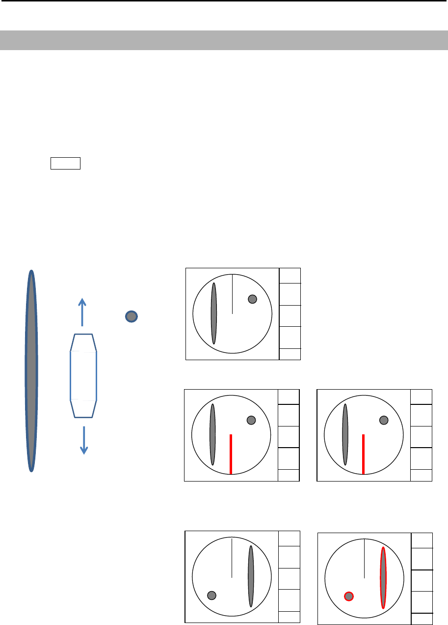
MDC-7000P/7900P Series Chapter 2 Radar Basic Operation
0093169006-05E 2-51
2.36 FERRY MODE
It is a function to use a river for by coming and going ferry etc.
It becomes effective at H UP, and the letter of the FERRY appears on the screen while using it.
[FERRY MODE] menu is not available by default.
Note: This menu is protected in normal. To cancel the protection, refer to 1.3 Menu usage “Display
[MAINTENANCE] menu”.
1 Press MENU key to display “Menu”.
Select [MAINTENANCE] => [STARTUP] => [FERRY MENU] to use [FERRY MODE] menu.
Selection values: [DISPLAY] => [FERRY MODE] =>
FERRY MODE: OFF, ON Turn ferry mode on or off
HDG: 0°, 180° Gyro reading has 180 degrees added to it or subtracted from it
HEADING LINE: UP, DOWN Change of the heading line indication up or down
90°
90°270°
270
°
BOW
90°T
STERN
270°T
FERRY MODE: OFF
FERRY MODE: ON
HDG: 0°
HEADING LINE: DOWN
FERRY MODE: ON
HDG: 180°
HEADING LINE: DOWN
90°
FERRY MODE: ON
HDG: 0°
HEADING LINE: UP
FERRY MODE: ON
HDG: 180°
HEADING LINE: UP
FERRY FERRY
FERRY FERRY
Note: HL line shows the direction
that the ship moves.
You can easily change it when you
set ferry mode at function key.
- This page intentionally left blank.-
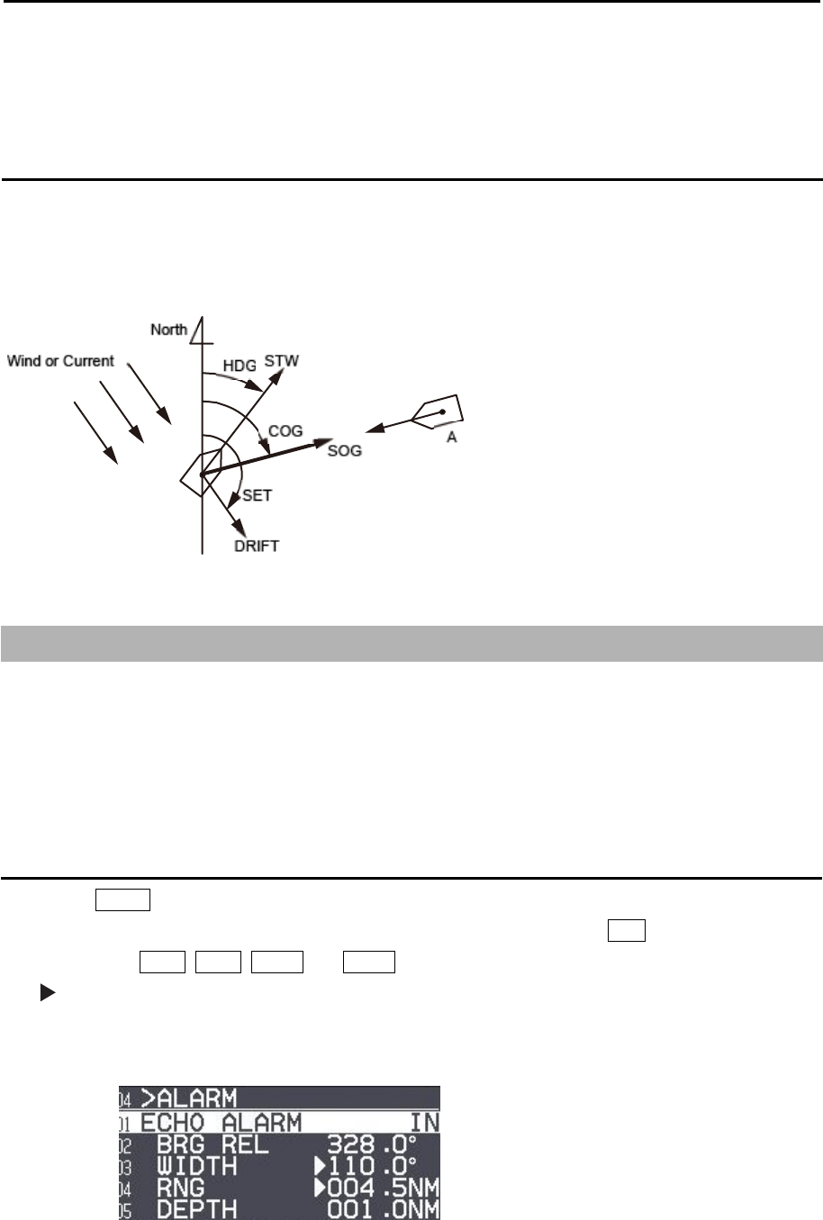
MDC-7000P/7900P Series Chapter 3 Alarm
0093169006-05E 3-1
Chapter 3 Alarm
This function is used to monitor hazardous targets such for collision prevention.
Collision avoidance
It is strongly recommended to maneuver the ship for collision avoidance based on true and dependable
SOG and COG information.
This is because ship's heading and running speed against water may be different from the actual ship's
movement due to foreign or mostly natural environmental effect such as wind, current, wave etc.
3.1 Echo alarm
Echo alarm function has two movement modes of [IN] and [OUT].
[IN] mode: When the echo enters a specified fan type alarm area, warning message will be displayed at
lower right of the display and an alarm will sound.
[OUT] mode: When echoes leave specified fan type alarm area, warning message will be displayed at
lower right of the display and an alarm will sound.
How to set echo alarm area (Fan type)
1 Press MENU key to display “Menu”.
Select [ALARM] => [ECHO ALARM] => select [IN] or [OUT], and press ENT key.
The color of EBL1, EBL2, VRM1 and VRM2 key’s light turn red.
symbol will be shown at the left of numerical indication of [BRG REL] or [WIDTH] and [RNG] or
[DEPTH] menu.
Blue dotted line of echo alarm area and orange dashed circle line will be displayed on the display.
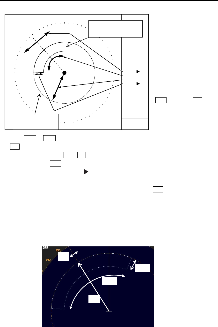
Chapter 3 Alarm MDC-7000P/7900P Series
0093169006-05E 3-2
3 Press EBL1 or EBL2 key, and select an item to be set between [BRG REL] and [WIDTH] by using
EBL knob.
In the same way, press VRM1 or VRM2 key, and select an item to be set between [RNG] and
[DEPTH] by using VRM knob.
The selected item is shown with a symbol at the left of numerical indication at the echo alarm in
the menu display.
4 When the setting of the echo alarm area is completed, then press ENT key, orange dashed circle
line will disappear, and echo alarm will be active.
5 There are additional items, [ALARM] => [DETECT LEVEL] => select [1 to 15]
It designates echo strength to determine an alarm sound.
1 means lowest signal echo level, 15 means highest signal echo level.
When the level is set too low, noise may cause false alarm.
Note: [DETECT LEVEL] is applied to the map area alarm function of next section.
Note: If the echo alarm area is set in the whole circumference, [WIDTH] needs to be set the 0.0˚
or 360.0˚.
WIDTH
BRG
RNG
DEPTH
VRM knob and EBL
knob are used for
setup.
BRG
ECHO ALARM
DEPTH
WIDTH
RNG
118°
2NM
45°
6NM
Blue dotted line of
echo alarm area
Orange dashed
circle line
ECHO ALARM IN
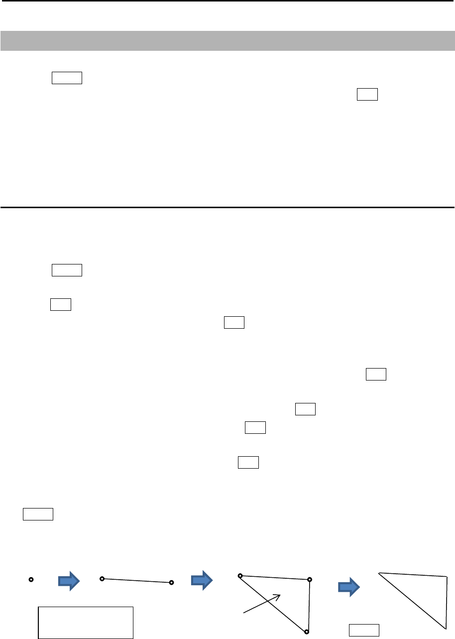
MDC-7000P/7900P Series Chapter 3 Alarm
0093169006-05E 3-3
3.2 Map area alarm
Map area alarm function provides alarm display when echo enters or leaves from the MAP AREA.
1 Press MENU key to display “Menu”.
Select [ALARM] => [MAP AREA ALARM] => select [IN] or [OUT], and press ENT key.
[IN] mode: When the echo enters a specified map area, warning message will be displayed at
lower right of the display and an alarm will sound.
[OUT] mode: When the echo leaves a specified map area, warning message will be displayed at
lower right of the display and an alarm will sound.
How to edit map area
There are two methods to edit map area. First method is to use cursor, second is to input
latitude/longitude via the menu.
Example: Cursor method
1 Press MENU key to display “Menu”.
Select [ALARM] => [MAP AREA ALARM] => [EDIT] => [CURSOR] => select [1 to 10] => [GO], and
press ENT key.
2 Move cursor to first input position, then press ENT key.
No.1 mark (small circle) is displayed with numerical number on the display, and numerical data
information is displayed in the “AREA INFO” area at right side on the display.
If necessary, Latitude and longitude data can be changed using cursor and ENT key by “AREA
INFO”. Also line color can be changed directly by using cursor by “AREA INFO”. If you want to
delete input data, move cursor to word “DELETE”, then press ENT key.
3 Move cursor to second input position, then press ENT key. No.2 mark is displayed, and a line is
generated from No.1 to No.2.
4 Move cursor to third input position, then press ENT key. No.3 mark is displayed, and a line is
generated from No.2 to No.3 and No.1 to No.3.
You can input up to 100 points. The minimum is three points. When input is completed, press
MENU key, numerical marks on the display will disappear, and map area alarm will be activated.
x: Block number
(1 to 10)
Press
MENU key
x-1 x-2 x-1 x-2
x-3
x-1
Alarm area
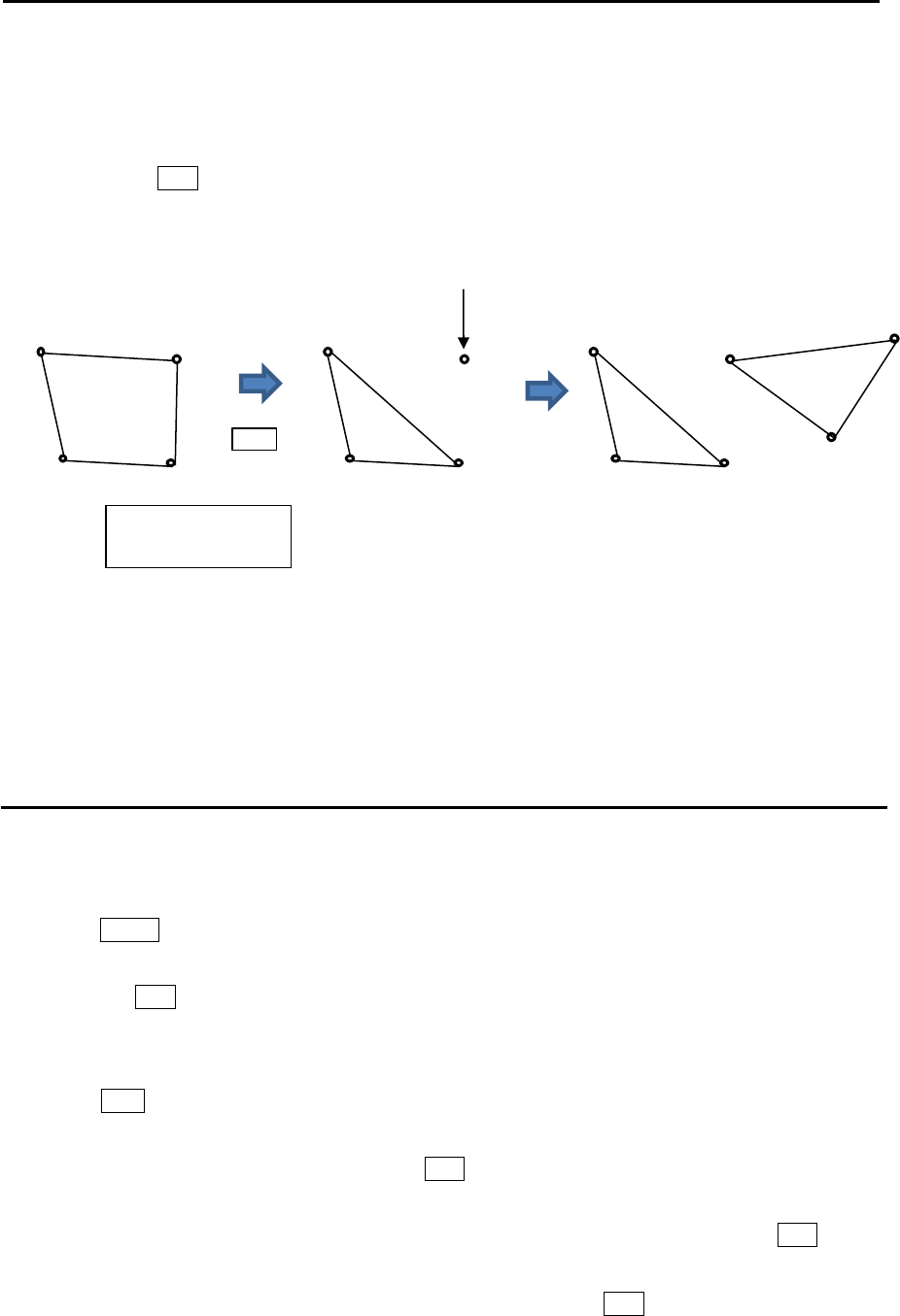
Chapter 3 Alarm MDC-7000P/7900P Series
0093169006-05E 3-4
x: Block number
(1 to 10)
5 The procedures to input plural divided map areas in the memory of same block number are as
follows. (Example)
After input the one map area (from x-1 to x-3), please input the start point of the new map area
(x-4). Press OFF key to divide the start point (x-4) from the first and last point (x-1, x-3).
Repeat operation of clause 3 and 4 mentioned previously (x-5, x-6).
6 There are additional items, [ALARM] => [DETECT LEVEL] => select [1 to 15]
It designates echo strength to determine an alarm sound.
1 means lowest signal echo level, 15 means highest signal echo level.
When the level is set too low, noise may cause false alarm.
Note: [DETECT LEVEL] is applied to the echo alarm function in previous section.
How to move map area
There are two methods to move map area position. First method is to use cursor, second is to input
latitude/longitude via the menu.
Example: Cursor method
1 Press MENU key to display “Menu”.
Select [ALARM] => [MAP AREA ALARM] => [MOVE] => [CURSOR] => select [1 to 10] => [GO],
and press ENT key.
2 Move cursor to the map area mark which you want to move to new positon, then change color or
delete position data.
3 Press ACQ key, middle circle mark will appear on the selected mark position, and numerical data
information is displayed in the “AREA INFO” at right side of the display.
4 Move cursor to new position, then press ENT key. Selected mark positon will move to new
positon.
Latitude and longitude position data can be changed directly by using cursor and ENT key by
“AREA INFO”. Line color can be changed directly by using cursor by “AREA INFO”. If you want to
delete selected data, move cursor to word “DELETE”, then press ENT key.
5 Repeat operation of clause 2 to 4 mentioned previously.
(x-4) point will be divided from (x-1, x-3).
x-1
x-2 x-3
x-4 x-1
x-2 x-3
x-4 x-1
x-2 x-3
x-4 x-5
x-6
Press
OFF key
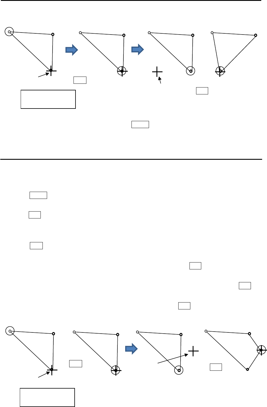
MDC-7000P/7900P Series Chapter 3 Alarm
0093169006-05E 3-5
6 When move operation is completed, press MENU key, numerical marks on the display will
disappear, and map area alarm function will be active.
How to add data to map area
There are two methods to add map area alarm position. First method is to use cursor, second is to input
latitude/longitude via the menu.
Example: Cursor method
1 Press MENU key to display “Menu”.
Select [ALARM] => [MAP AREA ALARM] => [ADD] => [CURSOR] => select [1 to 10] => [GO], and
press ENT key.
2 Move cursor on the map area mark before which you want to insert new mark, then change color
or delete position data.
3 Press ACQ key, middle circle mark will appear on the selected mark position, and numerical data
information is displayed in the “AREA INFO” at right side on the display.
4 Move cursor to new position where you want to add point, then press ENT key. New position point
will be inserted on the display.
Selected latitude and longitude position data can be changed directly by using cursor and ENT key
by “AREA INFO”. Line color can change directly using cursor by “AREA INFO”. If you want to
delete selected data, move cursor to word “DELETE”, then press ENT key.
x-1 x-2
x-3
x-1 x-2
x-3
x-1 x-2
x-3
x-1 x-2
x-3
Cursor
Press
ACQ key.
New position Press
ENT key.
x-1 x-2
x-3
x-1 x-2
x-3
x-1 x-2
x-3
x-1 x-2
x-4
x-3
Cursor
Press
ACQ key New
position
Press
ENT key
x: Block number
(1 to 10)
x: Block number
(1 to 10)
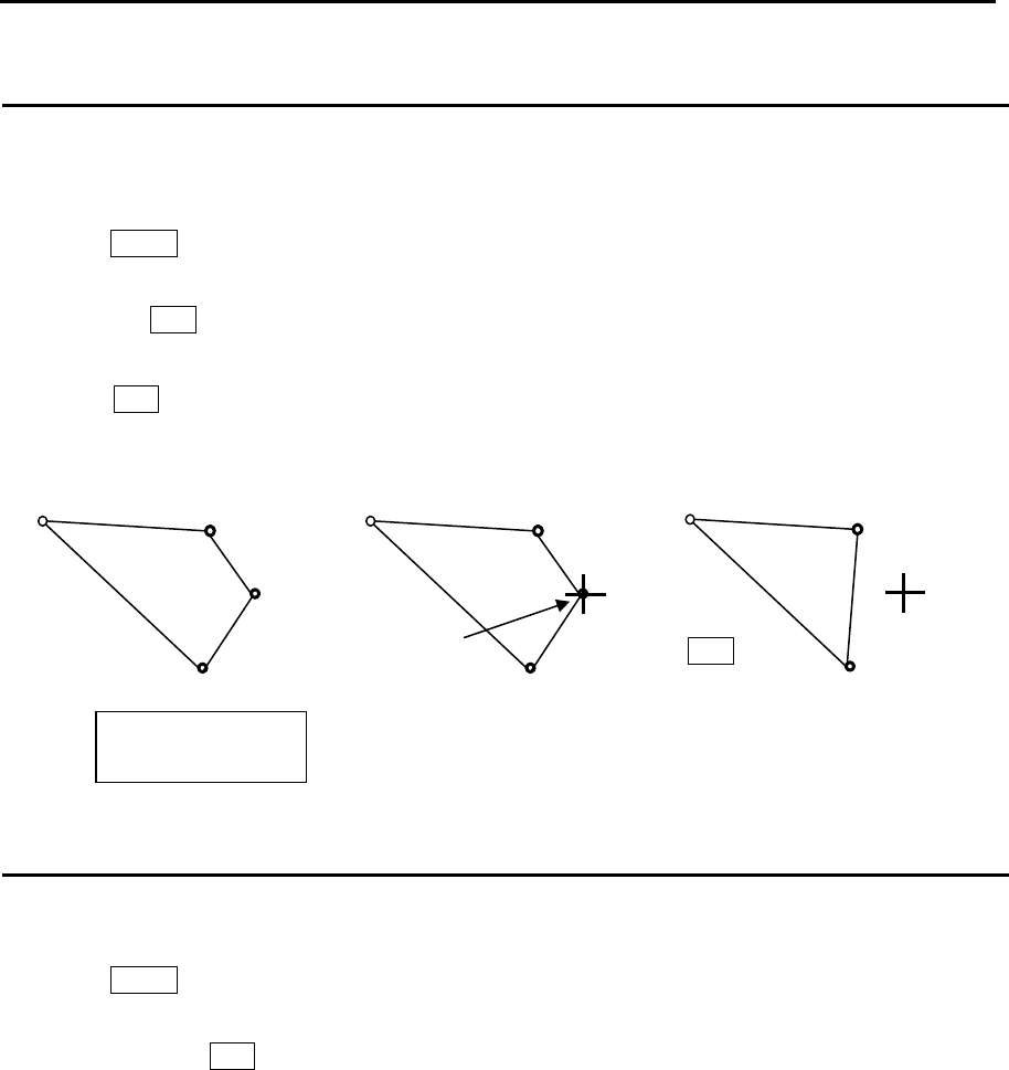
Chapter 3 Alarm MDC-7000P/7900P Series
0093169006-05E 3-6
How to delete the data of map area
There are two methods to delete map area alarm position. First method is to delete the point that is
selected by cursor, second is to select the number from the menu.
Example: Cursor method
1 Press MENU key to display “Menu”.
Select [ALARM] => [MAP AREA ALARM] => [DELETE] => [CURSOR] => select [1 to 10] => [GO],
and press ENT key.
2 Move cursor on the map area mark which you want to delete.
3 Press ENT key.
Selected map area position data will delete.
How to clear entire block of map area data
The map area data block can be cleared by using menu operation.
1 Press MENU key to display “Menu”.
Select [ALARM] => [MAP AREA ALARM] => [CLEAR] => [BLOCK NUMBER] => select [1 to 10] =>
[GO], and press ENT key.
Selected map area block will be cleared.
x-1 x-2
x-4
x-3
x-1 x-2
x-4
x-3
x-1 x-2
x-3
Press
ENT key
Cursor
x: Block number
(1 to 10)
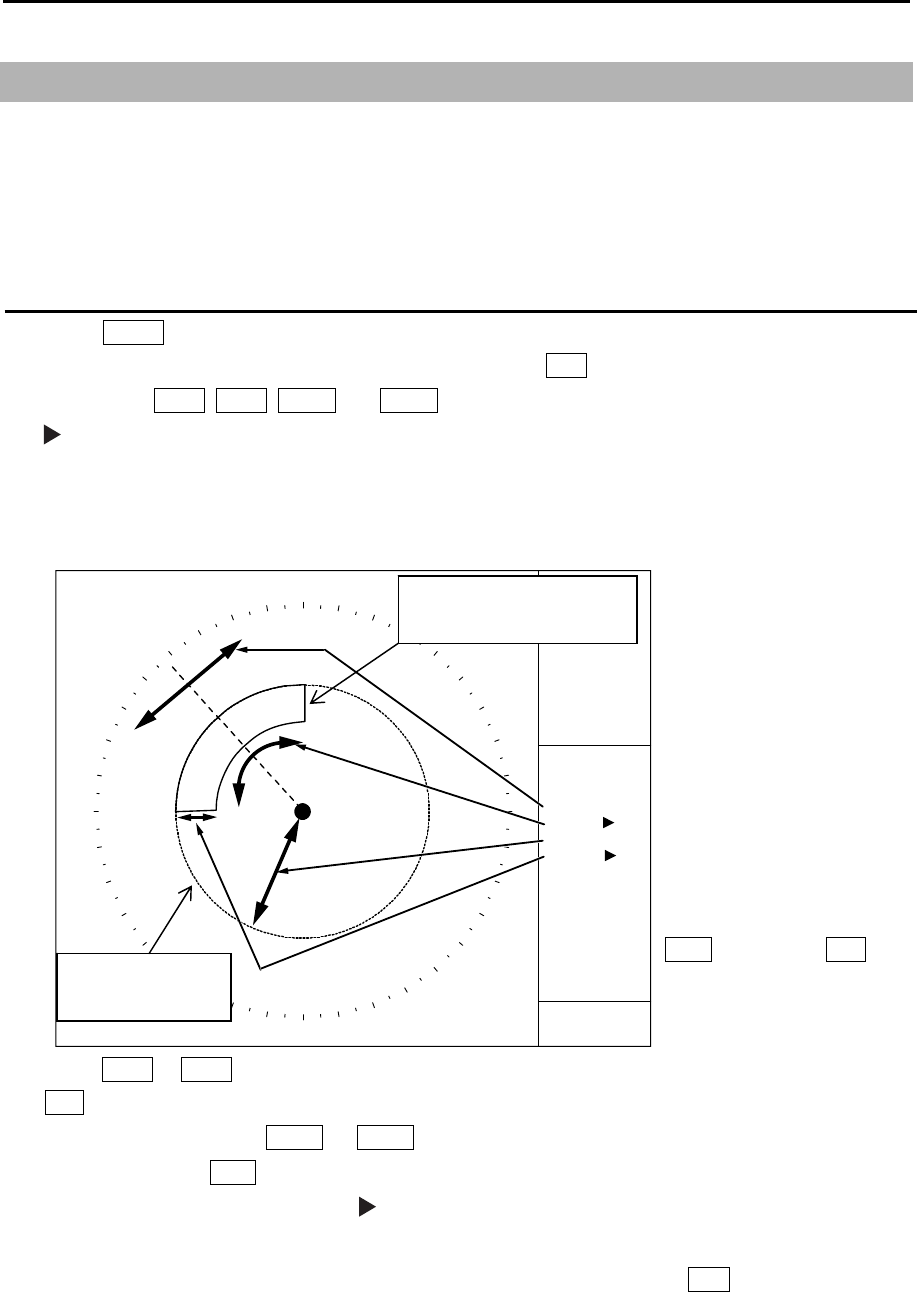
MDC-7000P/7900P Series Chapter 3 Alarm
0093169006-05E 3-7
3.3 Guard zone alarm
Guard zone alarm is an alarm system using TT (ARPA) tracked target or an AIS active target signal.
If a TT (ARPA) tracked target or an AIS active target enters a guard zone, then a large, red symbol is
displayed and [ALARM] is generated.
If a TT (ARPA) un-tracked target or an AIS sleeping target enters there, then no alarm is generated.
How to set guard zone alarm
1 Press MENU key to display “Menu”.
Select [ALARM] => [GUARD ZONE] => [ON], and press ENT key.
The color of EBL1, EBL2, VRM1 and VRM2 key’s light turns red.
symbol will be shown at the left of numerical indication of [BRG REL] or [WIDTH] and [RNG] or
[DEPTH] menu.
Blue dashed line of guard zone alarm area and orange dashed circle line will be displayed on the
display.
2 Press EBL1 or EBL2 key, and Select an item to be set between [BRG REL] and [WIDTH] by using
EBL knob.
In the same way, press VRM1 or VRM2 key, and select an item to be set between [RNG] and
[DEPTH] by using VRM knob.
The selected item is shown with a symbol at the left of numerical indication at the guard zone
alarm in the menu display.
3 When the setting of the guard zone alarm area is completed, then press ENT key, orange dashed
circle line will disappear, and guard zone area alarm will be activated.
Note: If the guard zone alarm area is set in the whole circumference, [WIDTH] needs to be set the 0.0˚
or 360.0˚.
BRG
ECHO ALARM
DEPTH
WIDTH
RNG
118°
2NM
45°
6NM
VRM knob and EBL
knob are used for
setup.
GZ ON
Blue dashed line of
guard zone alarm area
Orange dashed
circle line
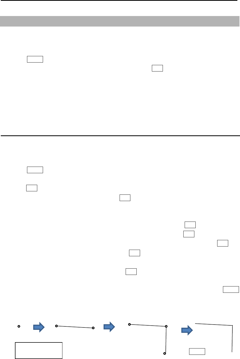
Chapter 3 Alarm MDC-7000P/7900P Series
0093169006-05E 3-8
3.4 Nav line cross
Nav line cross function enables to attract attention for safety navigation with alarm display when own
ship crosses the course preliminarily set (by cursor or latitude/longitude input).
1 Press MENU key to display “Menu”.
Select [ALARM] => [NAV LINE CROSS] => [ON], and press ENT key.
Note: When set [NAV LINE CROSS] menu to [OFF], this data will be displayed as line data of map that
looks like coast line.
Refer to 6.4 COAST LINE.
Refer to 6.5 NAV LINE.
How to edit
There are two methods to edit nav line cross alarm. First method is to use cursor, second is to input
latitude/longitude by the menu.
Example: Cursor method
1 Press MENU key to display “Menu”.
Select [ALARM] => [NAV LINE CROSS] => [EDIT] => [CURSOR] => select [1 to 10] => [GO], and
press ENT key.
2 Move cursor to first input position, then press ENT key. No.1 mark (small circle) is displayed with
numerical number on the display, and numerical data information is displayed in the “NAV LINE
INFO” area at right side on the display.
If necessary, latitude and longitude data can be changed using cursor and ENT key by “NAV LINE
INFO” area. Also line color can be changed directly by using cursor and ENT key by “NAV LINE
INFO” area. If you want to delete input data, move cursor to word “DELETE”, then press ENT key.
3 Move cursor to second input position, then press ENT key. No.2 mark is displayed, and a line is
generated from No.1 to No.2.
4 Move cursor to third input position, then press ENT key. No.3 mark is displayed, and a line is
generated from No.2 to No.3.
You can input up to 100 points. The minimum is two points. When input is completed, press MENU
key, numerical marks on the display will disappear, and nav line cross alarm will be activated.
x: Block number
(
1 to 10
)
Press
MENU key
x-1 x-2 x-1 x-2
x-3
x-1
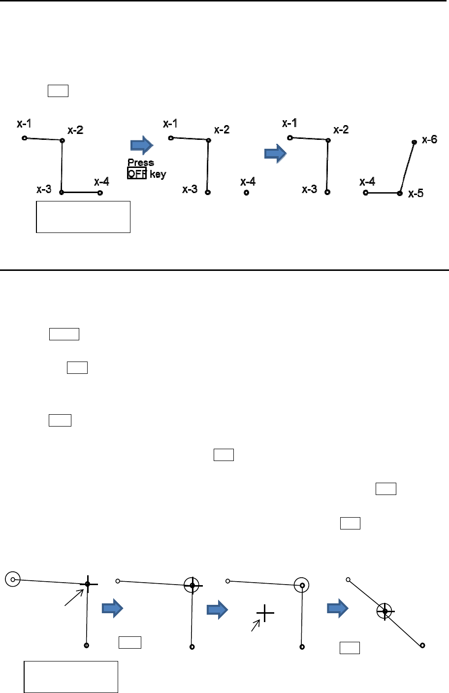
MDC-7000P/7900P Series Chapter 3 Alarm
0093169006-05E 3-9
5 The procedures to input plural divided nav line in the memory of same block number are as follows.
(Example)
After input the one nav line (from x-1 to x-3), please input the start point of the new nav line (x-4).
Press OFF key to divide the start point (x-4) from the last point (x-3).
Repeat operation of clause 3 and 4 mentioned previously (x-5, x-6).
How to move nav line
There are two methods to move nav line cross alarm. First method is to use cursor, second is to input
latitude/longitude by the menu.
Example: Cursor method
1 Press MENU key to display “Menu”.
Select [ALARM] => [NAV LINE CROSS] => [MOVE] => [CURSOR] => select [1 to 10] => [GO],
and press ENT key.
2 Move cursor to the nav line cross mark which you want to move to new positon, then change color
or delete position data.
3 Press ACQ key, medium circle mark will appear on the selected mark position, and numerical data
information will be displayed in the “NAV LINE INFO” area at right side on the display.
4 Move cursor to new position, then press ENT key. Selected mark positon will move to new
positon.
Latitude and longitude position data can be changed directly by using cursor and ENT key by “NA
LINE INFO”. Line color can be changed directly by using cursor by “NAV LINE INFO” area. If you
want to delete selected data, move cursor to word “DELETE”, then press ENT key.
5 Repeat operation of clause 2 to 4 mentioned previously.
Cursor
Press
ACQ key
x-1 x-2
x-3
x-1 x-2
x-3
x-1 x-2
x-3
x-1
x-2
x-3
Press
ENT key
New position
x: Block number
(1 to 10)
x: Block number
(1 to 10)
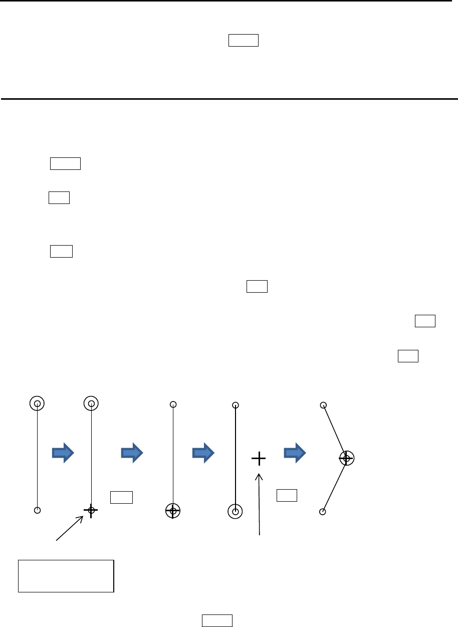
Chapter 3 Alarm MDC-7000P/7900P Series
0093169006-05E 3-10
6 When move operation is completed, press MENU key, numerical marks on the display will
disappear, and nav line cross alarm will be activated.
How to add
There are two methods to add nav line cross alarm position. First method is to use cursor, second is to
input latitude/longitude by the menu.
Example: Cursor method
1 Press MENU key to display “Menu”.
Select [ALARM] => [NAV LINE CROSS] => [ADD] => [CURSOR] => select [1 to 10] => [GO], and
press ENT key.
2 Move cursor to the nav line cross mark before which you want to add new mark, then change color
or delete position data.
3 Press ACQ key, medium circle mark will appear on the selected mark position, and numerical data
information is displayed in the “NAV LINE INFO” area at right side on the display.
4 Move cursor to new additional position, then press ENT key. New position point will be inserted on
the display.
Selected latitude and longitude position data can be changed directly using cursor and ENT key
via “NAV LINE INFO” area. Line color can be changed directly using cursor via “NAV LINE INFO”
area. If you want to delete selected data, move cursor to word “DELETE”, then press ENT key.
5 Repeat operation of clause 2 to 4 mentioned previously.
6 When add operation is completed, press MENU key, numerical marks on the display will disappear,
and nav line cross alarm will be activated.
x-1
x-2
x-1
x-2
x-1
x-2
x-1
x-2
x-1
x-2
x-3
x: Block number
(1 to 10)
Cursor
Press
ACQ key
New position
Press
ENT key
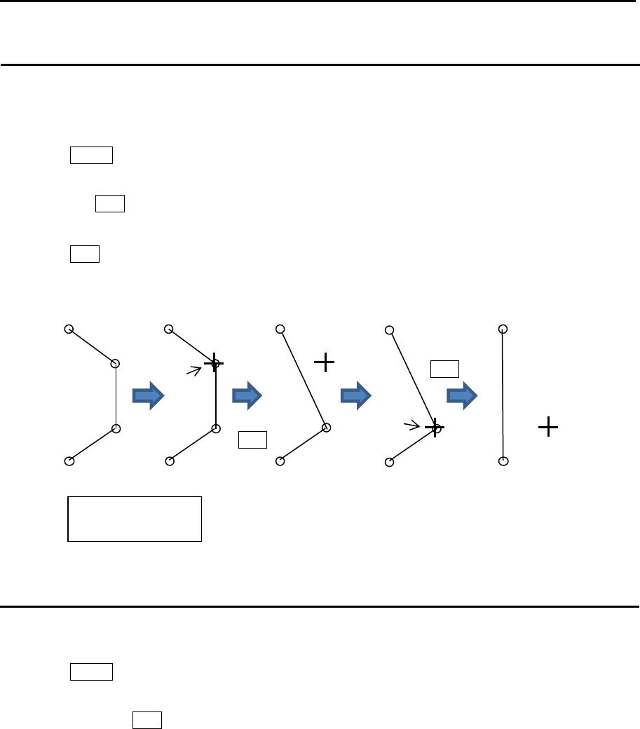
MDC-7000P/7900P Series Chapter 3 Alarm
0093169006-05E 3-11
How to delete
There are two methods to delete the data of nav line cross alarm position. First method is to delete the
point that is selected by cursor directly, second is to select the number from the menu.
Example: Cursor method
1 Press MENU key to display “Menu”.
Select [ALARM] => [NAV LINE CROSS] => [DELETE] => [CURSOR] => select [1 to 10] => [GO],
and press ENT key.
2 Move cursor to the nav line cross mark which you want to delete.
3 Press ENT key.
Selected nav line cross position data will be deleted.
How to clear
The nav line cross alarm data block can be cleared by using menu operation.
1 Press MENU key to display “Menu”.
Select [ALARM] => [NAV LINE CROSS] => [CLEAR] => [BLOCK NUMBER] => select [1 to 10] =>
[GO], and press ENT key.
Selected nav line cross alarm data block will be cleared.
x: Block number
(1 to 10)
Cursor
Press
ENT key
Cursor
Press
ENT key
x-1
x-2
x-3
x-4
x-1
x-2
x-3
x-4
x-1
x-2
x-3
x-1
x-2
x-3
x-1
x-2
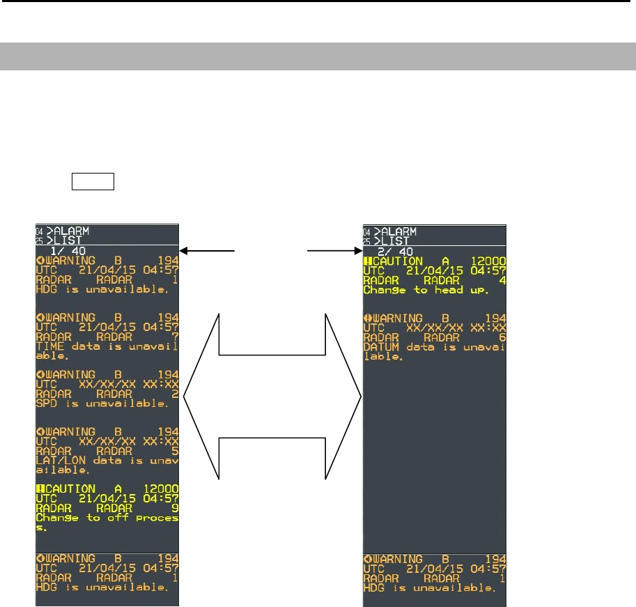
Chapter 3 Alarm MDC-7000P/7900P Series
0093169006-05E 3-12
3.5 Alarm List
List is an area that displayed a list of currently present alarms.
It lists the alarms activated by the error device selected by the after-mentioned [PRIORITY] in
chronological order from top to bottom. Then, it lists the alarms of other error devices in the same order.
1 Press MENU key to display “Menu”.
Select [ALARM] => [LIST] =>
Alarm goes off automatically when cause of alarm disappears.
Up and down roll
action of the
trackball turns pages
A
larm lis
t
page
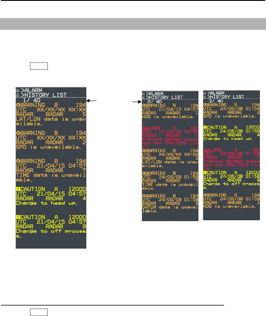
MDC-7000P/7900P Series Chapter 3 Alarm
0093169006-05E 3-13
3.6 Alarm History list
Alarm History List is an area that displayed a list of past alarms.
It lists the alarms activated in the past in chronological order from top to bottom.
1 Press MENU key to display “Menu”.
Select [ALARM] => [HISTORY LIST] =>
Maximum number of alarms which can be displayed is 200. Alarms in excess of 200 are deleted.
The up and down roll action of the trackball turns 40 pages.
History List Sort menu sorts the indication contents of History List.
1 Press MENU key to display “Menu”.
Select [ALARM] => [HISTORY LIST SORT] => [PRIORITY, CATEGORY or TIME] =>
[PRIORITY] => ALL, ALARMS, WARNINGS or CAUTIONS
Sorts the kinds of alerts
[CATEGORY] => ALL, A or B
Sorts the kinds of category
[TIME] => LAST IN or FIRST IN
Choose a turn of the indication
A
larm histor
y
List page

Chapter 3 Alarm MDC-7000P/7900P Series
0093169006-05E 3-14
3.7 Alarm on/off (TT and AIS)
This function is to set auto acquisition target (TT and AIS) alarm function on or off which is set by
[TARGET] => [AUTO ACQ AREA] menu.
[AUTO ACQ] function [ON] activates the alarm function when TT and/or AIS target enters designated
auto acquisition area.
[MESSAGE] function of [ALARM] => [ALARM ON/OFF] => [AIS] menu is the alarm of received
message.
When AIS receive a message for own ship, alarm information is displayed on alarm display area, and
select AIS symbol automatically to know the sender.
Using AIS message alarm function user must input own ship MMSI number correctly.
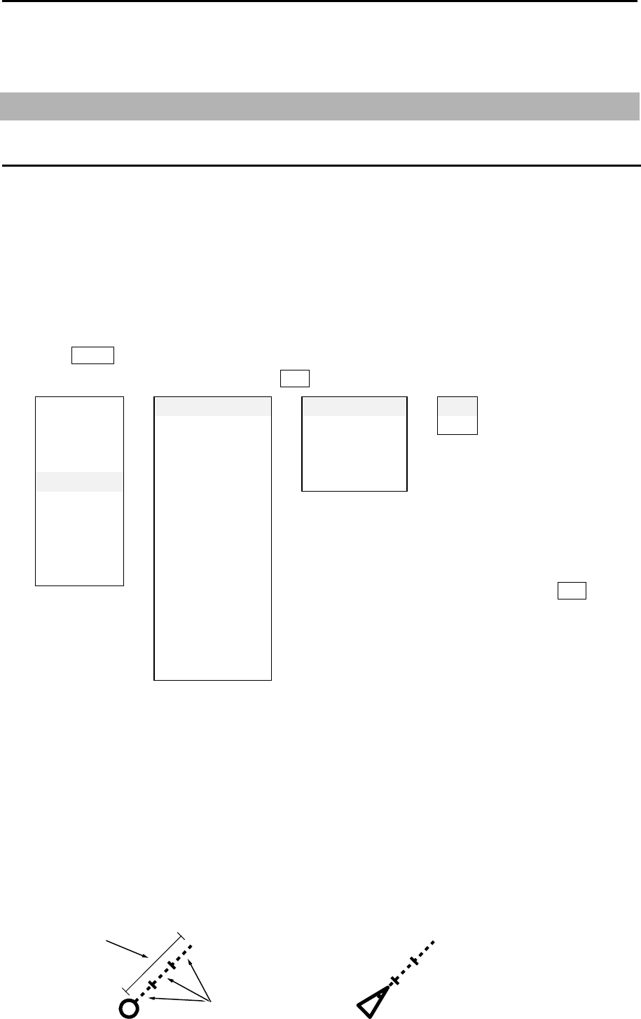
MDC-7000P/7900P Series Chapter 4 Target (AIS,TT and Trial manoeuvre)
0093169006-05E 4-1
TIME
TIME INCREMENT: 3
Chapter 4 Target (AIS, TT and Trial manoeuvre)
4.1 Common setting
VECTOR REL/TRUE
The course and speed are indicated as vector after tracking is established.
Two types of display mode are available: relative display (REL) and true display (TRUE).
REL: This vector adds the course/speed of a target to the course/speed of own ship.
If the vector is directed towards own ship, possibility of collision exists.
It shows danger of collision at a glance and is useful to avoid collision.
TRUE: This vector shows the course/speed of a target only, regardless of own ship.
1 Press MENU key to display “Menu”.
Select [TARGET] => [VECT], and press ENT key after making selection.
2 In addition, there are [TIME], [TIME INCREMENT], [STAB INDICATOR] and [PATH INDICATOR]
setups.
[TIME]: It designates length of vector by time. When [TIME] is specified by 1 min, the vector is
displayed to the position that will be reached in 1 min by present target speed.
Selection values: OFF, 30sec, 1min, 3min, 6min, 12min, 30min, 60min
[TIME INCREMENT]: This vector displays the division number of time divider. When the setup
value is 2, vector is 1/2 and the parting line is displayed at a half-length
location of vector.
Selection values: OFF, 2, 3, 5, 10
Note: [TRUE / REL] and [TIME] can
be changed directly at the upper right
of the display, with trackball and ENT
key, without using menu.
ECHO ⇒VECT ⇒TRUE/REL ⇒TRUE
TRA IL CPA /TCPA TIME REL
DISPLA Y A IS ID DISP TY PE TIME INCREMENT
ALARM TT ID DISP TYPE STAB INDICATOR
TA RGET ID DISP SIZ E PA TH PREDICTOR
NAV TOOL INPUT RNG
MAP ASSOCIATION
BRILL AUTO ACQ AREA
SYSTEM BRG REL
MA INTENA NCE WIDTH
RNG
DEPTH
AIS
TT
TRIA L MANOEUVRE
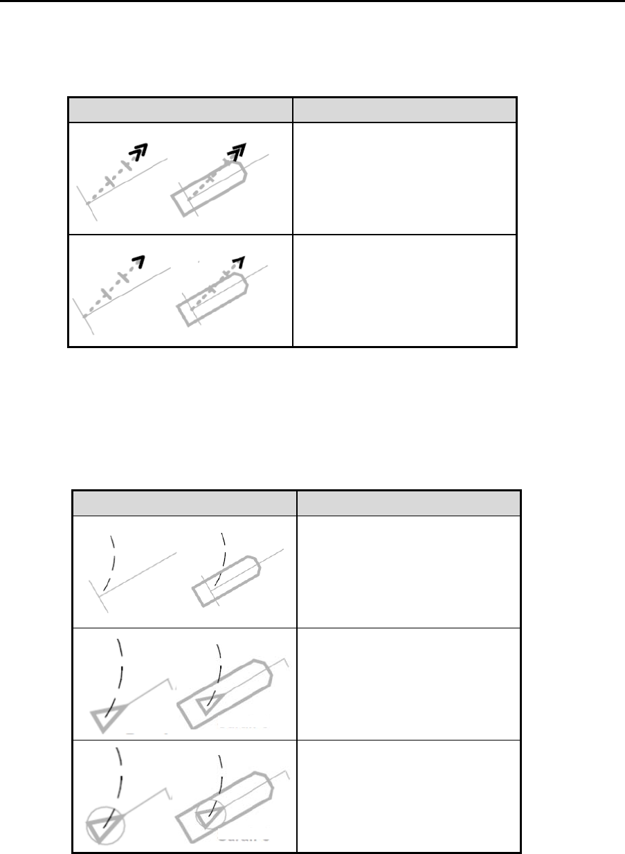
Chapter 4 Target (AIS, TT and Trial manoeuvre) MDC-7000P/7900P Series
0093169006-05E 4-2
Symbol Symbol name
GNG indicator
(Double arrowhead)
SEA indicator
(Single arrowhead)
Symbol Symbol name
Own ship path predictor
AIS target predictor
Associated target path predictor
[STAB INDICATOR]: This function is to display the mark of GND or SEA stabilization on the end of
own ship vector.
STAB INDICATOR is displayed only when VECTOR is displayed.
STAB INDICATOR is not displayed when PATH PREDICTOR is “on”.
[PATH PREDICTOR]: This function is to display a path predictor in place of a velocity vector as a
curved line.
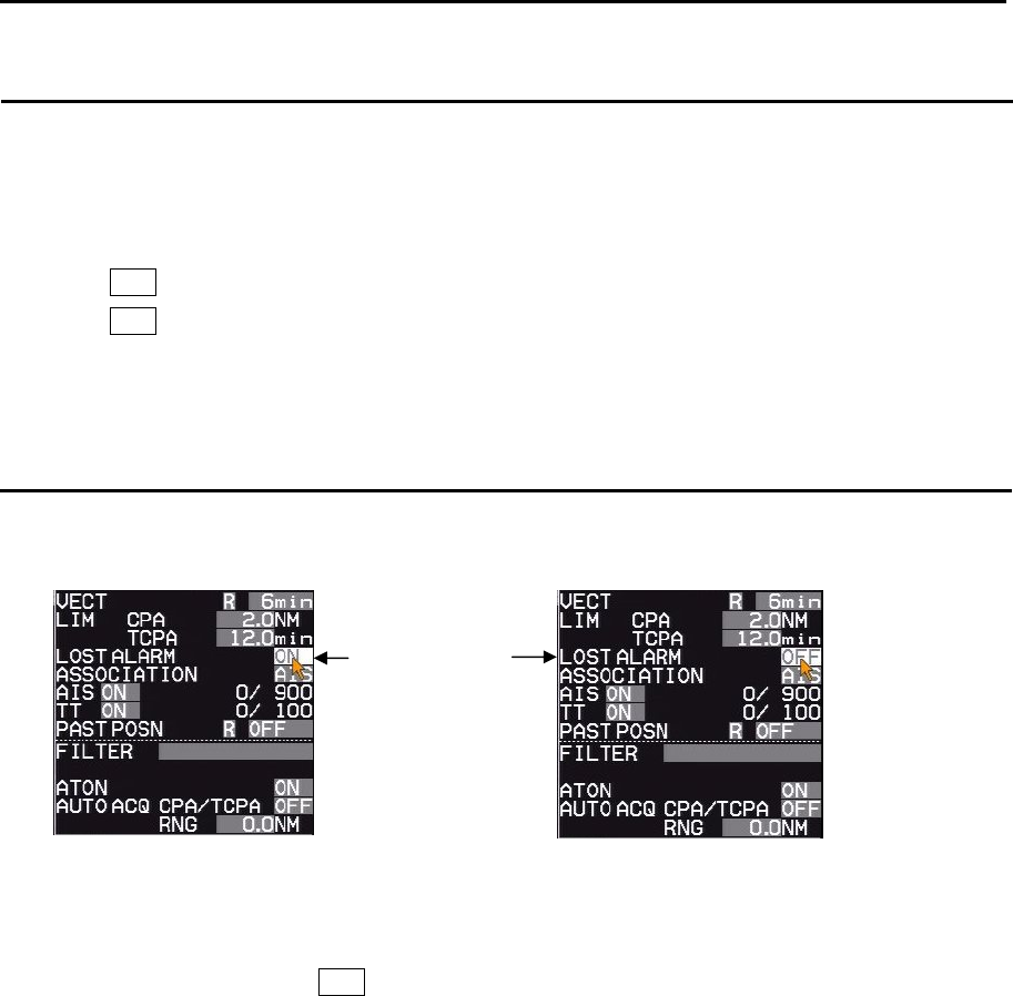
MDC-7000P/7900P Series Chapter 4 Target (AIS,TT and Trial manoeuvre)
0093169006-05E 4-3
CPA/TCPA alarm
The menu of “[TARGET] => [CPA/TCPA]” sets the alarm function ON or OFF.
To avoid collision, it sets up LIMIT CPA (closest point of approach) and LIMIT TCPA (time to CPA).
[LIMIT CPA] and [LIMIT TCPA] can be changed directly at the upper right of the display.
1 Move the cursor to set the value window of [CPA] at the upper right of the display.
Press ENT key and change the setting value with the trackball.
Press ENT key to save after changing the setup value.
2 In addition, [LIMIT TCPA] is used to specify limit by time.
LOST ALARM
LOST ALARM function of target status area can be changed lost alarm ON or OFF mode of TT (ARPA)
and AIS target.
1 When LOST ALARM is ON, lost target symbol is displayed on the last reported (known or
predicted) target position and a lost target warning is appeared on alarm area display until
confirmation operation with OFF key.
2 When LOST ALARM is OFF, lost target symbol is not displayed, and does not appear lost alarm
message on alarm area display.
Note: When Sleeping lost of AIS alarm mode sets to OFF, Lost of AIS sleeping target will delete without
using confirmation operation.
Refer to 4.2 AIS “AIS alarm [Sleeping lost]”.
LOST ALARM
function
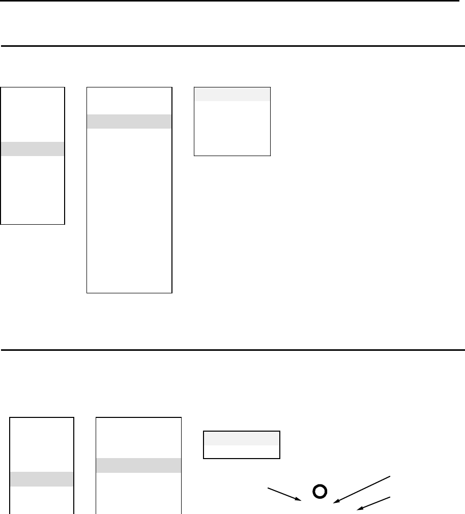
Chapter 4 Target (AIS, TT and Trial manoeuvre) MDC-7000P/7900P Series
0093169006-05E 4-4
Set AIS ID DISP TYPE
ID can be displayed with AIS target.
Set items: NUMBER, NAME, MMSI, IMO and CALLSIGN
Set TT ID DISP TYPE
ID can be displayed with TT (ARPA) target.
Set items: NUMBER and LABEL
ECHO ⇒VECT
TRA IL CPA /TCPA NUMBER ON/OFF
DISPLA Y A IS ID DISP TY PE ⇒LABEL ON/OFF
A LA RM TT ID DISP TYPE
TA RGET ⇒ID DISP SIZE
NAV TOOL INPUT RNG
MAP ASSOCIATION
R1
Number
Reference number
Label
5
Sarah J
Refer to 4.3 TT (ARPA) “Reference target acquisition”
about reference number.
ECHO V ECT NUMBER ON/OFF
TRAIL CPA/TCPA NAME ON/OFF
DISPLA Y A IS ID DISP TY PE ⇒MMSI ON/OFF
ALARM TT ID DISP TYPE IMO ON/OFF
TA RGET ⇒ID DISP SIZE CA LLSIGN ON/OFF
NAV TOOL INPUT RNG
MAP ASSOCIATION
BRILL AUTO ACQ AREA
SYSTEM BRG REL
MA INTENA NCE WIDTH
RNG
DEPTH
AIS
TT
TRIA L MANOEUVRE

MDC-7000P/7900P Series Chapter 4 Target (AIS,TT and Trial manoeuvre)
0093169006-05E 4-5
Set ID DISP SIZE
This menu is used to specify display ID size.
Selection values: X-SMALL, SMALL, MEDIUM, LARGE
Set Input range
This is to set up the operation range of TT (ARPA) and AIS.
It designates the entire operation range of TT (ARPA) and AIS. So, TT (ARPA) and AIS do not function
outside of the range.
1 Press MENU key to display “Menu”.
Select [TARGET] => [INPUT RNG], and press ENT key after selecting the setup value.
Selection values: 1.0NM to 64.0NM
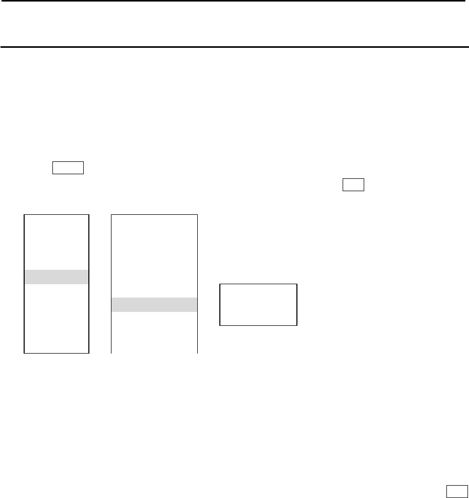
Chapter 4 Target (AIS, TT and Trial manoeuvre) MDC-7000P/7900P Series
0093169006-05E 4-6
ASSOCIATION
When an AIS target and a tracked target of TT (ARPA) are the same target, it is automatically
associated to a single target.
Select priority of the association with either AIS or TT (ARPA).
If the low-speed ship is associated and displayed with TT priority, then HDG may be unstable. So, the
display with AIS priority is recommendable.
1 Press MENU key to display “Menu”.
Select [TARGET] => [ASSOCIATION] => [ASSOCIATION], and press ENT key after selecting the
setup value.
OFF: Association is turned off.
TT: Symbols of both TT (ARPA) and AIS are associated to TT (ARPA). However when the target of
AIS is sleeping target it is not associated.
AIS: Symbols of both TT (ARPA) and AIS are associated to AIS. However when the target of AIS is
sleeping target it is not associated.
[ASSOCIATION] can be changed directly at the upper right of the display, with trackball and ENT
key, without using menu function.
In addition, [CHG SELECTED TGT] and [SETTING] are provided.
[ASSOCIATION] changes priority of the association of all targets while [CHG SELECTED TGT]
changes priority of the association for selected target only.
[SETTING] designates conditional items of association among RNG, CRS, SPD, SPD LIM and
TIME REPRIEVE.
RNG: It designates the range to determine association. (0.001NM to 1.000NM)
CRS: It designates the course to determine association. (10.0° to 60.0°)
SPD: It designates the speed difference to determine association. (1.0kn to 20.0kn)
SPD LIM: It designates the minimum speed to determine association. (1.0kn to 10.0kn)
TIME REPRIEVE: It designates the time to determine association. (1sec to 99sec)
ECHO V ECT
TRA IL CPA /TCPA
DISPLA Y A IS ID DISP TY PE
ALA RM TT ID DISP TY PE
TA RGET ⇒ID DISP SIZ E
NAV TOOL INPUT RNG ASSOCIA TION OFF/TT/AIS
MAP ASSOCIATION ⇒
CHG SELECTED TGT
BRILL A UTO ACQ AREA SETTING RNG/CRS/SPD/SPD LIM/TIME REPRIEVE
SYSTEM BRG REL
MA INTENA NCE WIDTH
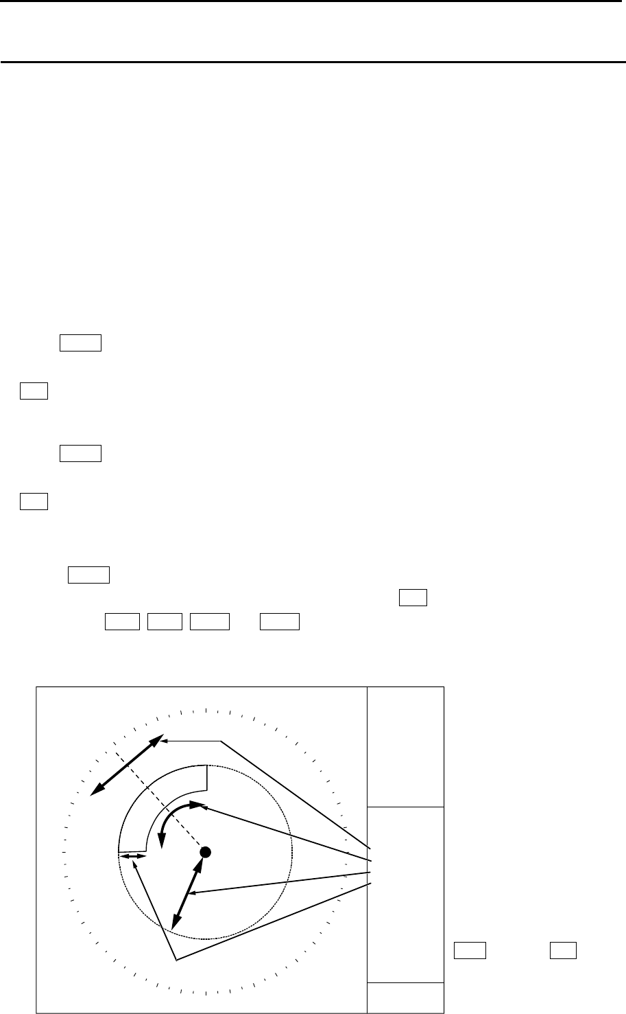
MDC-7000P/7900P Series Chapter 4 Target (AIS,TT and Trial manoeuvre)
0093169006-05E 4-7
Automatic acquisition area
AUTO ACQ AREA is function that is used for automatic acquisition of TT or AIS targets that enter area
designated in a fan type range.
TT: When an un-tracked target enters, it is automatically acquired and an alarm sounds.*1
When a tracked target enters, no alarm sounds.
AIS: When a sleeping target enters, it is changed to an active target (activated) and an alarm sounds.*2
When an active target enters, no alarm sounds.
It takes at least 20 seconds before target is acquired by TT (ARPA).
Take note that the target may not be acquired when the setting area is too narrow or target is moving at
high speed.
*1: Press MENU key to display “Menu”.
Select [ALARM] => [ALARM ON/OFF] => [TT] => [AUTO ACQ] => select [ON] or [OFF], and press
ENT key.
Select [OFF], alarm sound will be disappeared.
*2: Press MENU key to display “Menu”.
Select [ALARM] => [ALARM ON/OFF] => [AIS] => [AUTO ACQ] => select [ON] or [OFF], and press
ENT key.
Select [OFF], alarm sound will be disappeared.
1 Press MENU key to display “Menu”.
Select [TARGET] => [AUTO ACQ AREA] => [ON], and press ENT key.
The color of EBL1, EBL2, VRM1 and VRM2 key’s light turn red.
2 Setup area. (Method using the cursor)
The items to be selected are [BRG REL], [WIDTH], [RNG], and [DEPTH]
BRG
ECHO ALARM
DEPTH
WIDTH
RNG
118°
2NM
45°
6NM
VRM knob and EBL
knob are used for
setup.
AUTO ACQ AREA
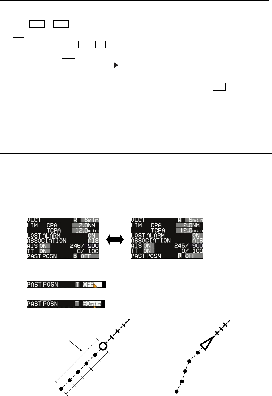
Chapter 4 Target (AIS, TT and Trial manoeuvre) MDC-7000P/7900P Series
0093169006-05E 4-8
PAST POSN TIME
1/5
1/5
1/5
1/5
1/5
3 Press EBL1 or EBL2 key, and select an item to be set between [BRG REL] and [WIDTH] by using
EBL knob.
In the same way, press VRM1 or VRM2 key, and select an item to be set between [RNG] and
[DEPTH] by using VRM knob.
The selected item is shown with a symbol at the left of numerical indication at the auto
acquisition area in the menu display.
4 When the setting of the automatic acquisition area is completed, then press ENT key, AUTO ACQ
AREA will be activated.
Note: If AUTO ACQ AREA is set in the whole circumference, [WIDTH] needs to be set the 0.0˚ or 360.0˚.
PAST POSN: Past position
The past position of TT (target tracking) and AIS (activated target) can be displayed.
1 Move the cursor to set value window of [PAST POSN] upper right part of the display.
Press ENT key to select [T] or [R].
Note: [TRUE/REL] is in common with [TRAIL] (Refer to 2.19 Target trail). So, if you change one
part, the other part will change accordingly.
2 [PAST POSN TIME] item designates recording length.
Up to five record points are available.
Setting value: OFF, 30sec, 1min, 3min, 6min, 12min, 30min, 60min
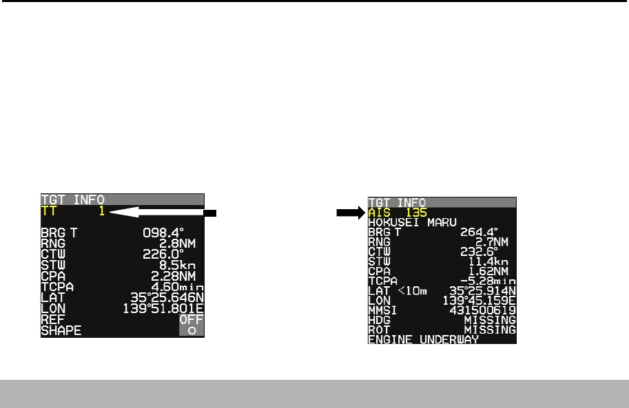
MDC-7000P/7900P Series Chapter 4 Target (AIS,TT and Trial manoeuvre)
0093169006-05E 4-9
Note: The past position by its nature records and displays past positions. Immediate display is
impossible after the start of TT (ARPA) and after the change from AIS sleep target to active target.
In addition, when [TIME] is changed, a past positon record is reset (erased). So, immediate
display is impossible.
In above case, TT or AIS target number characters in [TGT INFO] message at right of the display
change to yellow. When “PAST POSN” setting time has passed, character color turns white.
4.2 AIS
The AIS communicates with other ships via VHF (Very High Frequency) radio by transmitting your
ship information and by receiving other ships information.
Only AIS data with WGS84 datum is accepted.
If AIS data has no datum or if datum is other than WGS84, then the warning of [AIS datum is not
WGS84] appears. AIS data is not displayed.
Capable of displaying up to 900 other ship symbols/IDs.
If the displayed targets exceed 855, then caution is displayed at the lower right of the display.
AIS target count number at the upper right of the display changes to yellow.
If the displayed targets exceed 900, then warning is displayed at the lower right of the display.
AIS target count number at upper right of the display changes to red.
In that case, change [TARGET] => [INPUT RNG] value and decrease the displayed targets.
Note:
• If the displayed targets exceed 900, then next coming AIS data cannot be displayed. For the sake of
safety, if warning is displayed, then change [INPUT RNG] value immediately and decrease the
displayed targets.
• If the own ship information display at upper right of the display is turned orange, then it means that the
input sentence is incomplete. So, this function does not work.
If AIS is used in combination with [ASSISTANT DISP], then AIS is effective.
Target number

Chapter 4 Target (AIS, TT and Trial manoeuvre) MDC-7000P/7900P Series
0093169006-05E 4-10
Enable AIS function
There are two methods to enable this function. One is [ON/OFF] using menu. The other is [ON/OFF] of
[AIS] at the upper right of the display using cursor.
1 Press MENU key to display “Menu”.
Select [TARGET] => [AIS] => [AIS] => [ON], and press ENT key.
Select ID
This is to change the target selected by using [ACTIVE/SLEEP].
1 Press MENU key to display “Menu”.
Select [TARGET] => [AIS] => [SELECT ID], and press ENT key after selecting the setup value.
Selection values: 101 to 1000
ACTIVE/SLEEP
This is to change ACTIVE/SLEEP of the target selected by [SELECT ID] function.
The change of ACTIVE/SLEEP can be executed also by using trackball, moving a cursor to the desired
target, then press ENT key.
Ship outline
Ship outline function is displayed only when OUTLINE is included in the target information received by
AIS.
Ship outline is not displayed if it is less than 3 mm in size of the display, and it is not displayed when
own ship outline is OFF.
(Refer to 4.2 AIS “Types of AIS target symbol”)
(Refer to [NAV TOOL] => [SHIP OUTLINE] => [SHIP OUTLINE] and [OS PROFILE])
1 Press MENU key to display “Menu”.
Select [TARGET] => [AIS] => [SHIP OUTLINE] => [ON], and press ENT key.
Selection values: OFF, ON
HDG line
This is displayed only when HDG LINE is included in the target information received by AIS.
(Refer to 4.2 AIS “Types of AIS target symbol”)
1 Press MENU key to display “Menu”.
Select [TARGET] => [AIS] => [HDG LINE] => [ON], and press ENT key.
Selection values: OFF, ON

MDC-7000P/7900P Series Chapter 4 Target (AIS,TT and Trial manoeuvre)
0093169006-05E 4-11
Turn indicator
This is displayed only when HDG LINE is included in the target information received by AIS.
(Refer to 4.2 AIS “Types of AIS target symbol”)
1 Press MENU key to display “Menu”.
Select [TARGET] => [AIS] => [TURN INDICATOR] => [ON], and press ENT key.
Selection values: OFF, ON
OS display
This is to turn own ship AIS symbol ON or OFF.
1 Press MENU key to display “Menu”.
Select [TARGET] => [AIS] => [OS DISP] => [ON], and press ENT key.
Selection values: OFF, ON
OS MMSI
This menu is where user can enter MMSI number of own ship.
MMSI number is necessary to be able to receive message for own ship.
1 Press MENU key to display “Menu”.
Select [TARGET] => [AIS] => [OS MMSI] => set numbers, and press ENT key.
Selection values: 0 to 1073741824
Message display
This is to set up displayed speed when message is included in AIS information.
Message is displayed at “AIS INFO” of ASSISTANT DISP.
1 Press MENU key to display “Menu”.
Select [TARGET] => [AIS] => [MESSAGE DISP], and press ENT key after selecting the setup
value.
Selection values: OFF, SLOW, MEDIUM, FAST
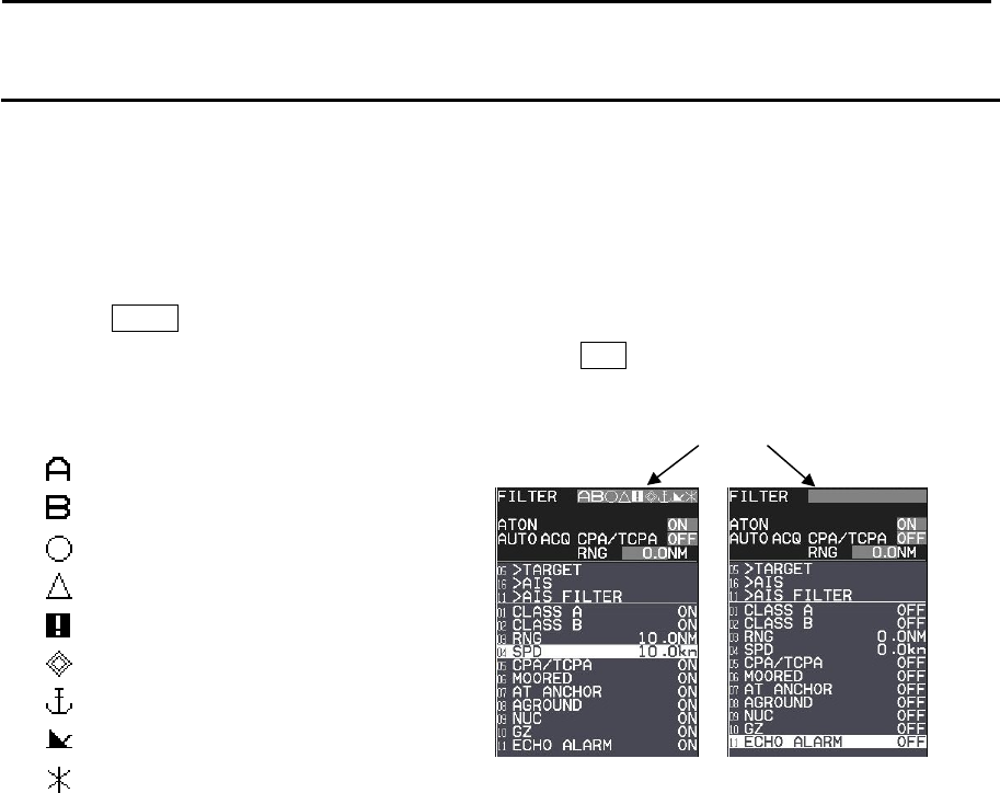
Chapter 4 Target (AIS, TT and Trial manoeuvre) MDC-7000P/7900P Series
0093169006-05E 4-12
AIS filter
When there are many AIS targets, the display may become unclear. In that case, by setting AIS FILTER,
it is possible to hide unnecessary sleeping targets or to display the necessary targets only, and the
clear view of the target can be achieved.
Note: The filter is absolutely used to limit display. When input is to be limited, [INPUT RNG] shall be
operated.
1 Press MENU key to display “Menu”.
Select [TARGET] => [AIS] => [AIS FILTER], and press ENT key after selecting the setup value.
Selection values:
CLASS A: OFF, ON
CLASS B: OFF, ON
RNG: 0.0 to 64.0NM
SPD: 0.0 to 100.0kn
CPA/TCPA: OFF, ON
MOORED: OFF, ON
AT ANCHOR: OFF, ON
AGROUND: OFF, ON
NUC: OFF, ON
GUARD ZONE: OFF, ON Exclude from RNG filter.
ECHO ALARM: OFF, ON Exclude from RNG filter.
AIS filter indication
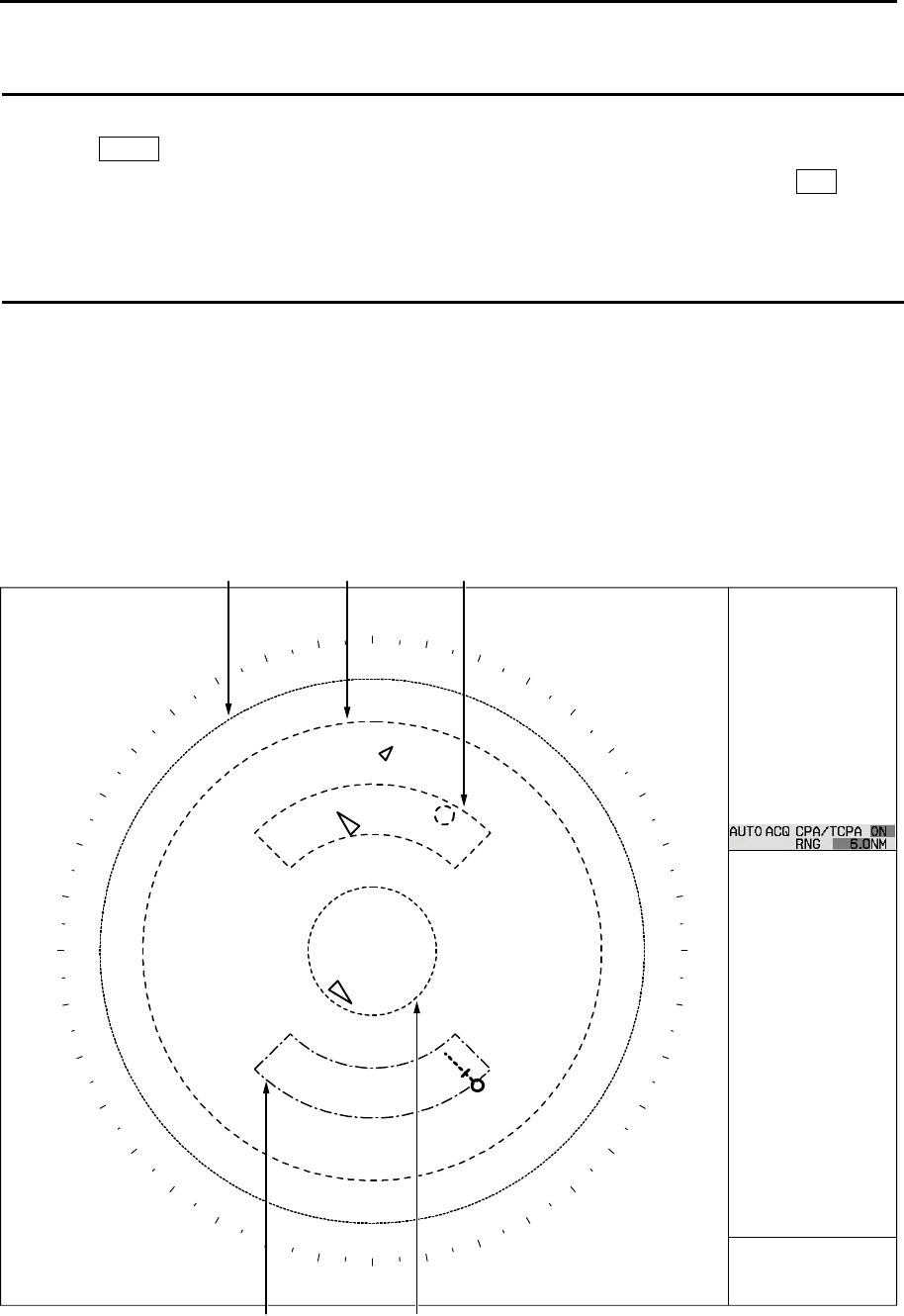
MDC-7000P/7900P Series Chapter 4 Target (AIS,TT and Trial manoeuvre)
0093169006-05E 4-13
AIS alarm [Sleeping lost]
When sleeping target disappears, AIS alarm will come on.
1 Press MENU key to display “Menu”.
Select [TARGET] => [AIS] => [AIS ALARM] => [SLEEPING LOST] => [ON], and press ENT key.
Selection values: OFF, ON
AIS auto ACQ
When sleeping target enters the “AUTO ACQ AREA” or “AIS AUTO ACQ”, sleeping targets is changed
to active target.
“AUTO ACQ AREA” is applied to both “AIS” and “TT (ARPA)”. (Refer to 4.1 Common setting “Automatic
acquisition area”.)
The range of “AIS AUTO ACQ” sets up in the “Target status” area at right side on the display.
AUTO ACQ AREA (TT, AIS)
AIS AUTO ACQ
INPUT RNG
GUARD ZONE
FILTER RNG
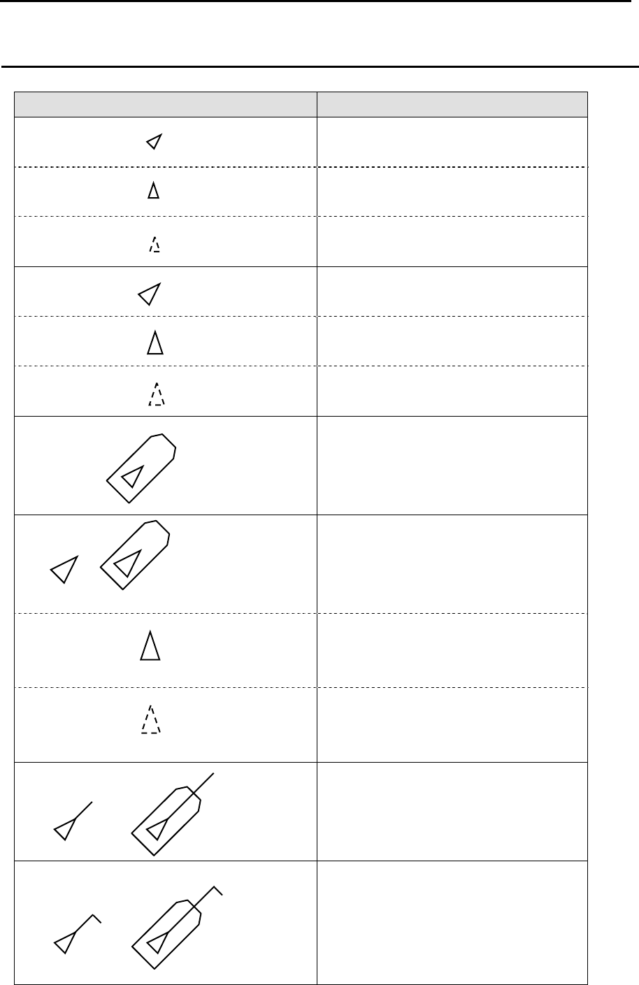
Chapter 4 Target (AIS, TT and Trial manoeuvre) MDC-7000P/7900P Series
0093169006-05E 4-14
Types of AIS target symbol
The following symbols are overlapped on target.
Symbol Symbol name
Sleeping target
Sleeping target without HDG.
Sleeping target with neither reported
HDG nor COG.
Activated target
Activated target without HDG.
Activated target with neither reported
HDG nor COG.
Activated target - true scaled outlines
Blink in 0.5 sec. interval
Activated target - dangerous targets
Blink in 0.5 sec. interval
Activated target without HDG.
Blink in 0.5 sec. interval
Activated target with neither reported
HDG nor COG.
Activated target with heading lines
Activated target with turn indicators
*
*
*
*
*
*
*
*
*
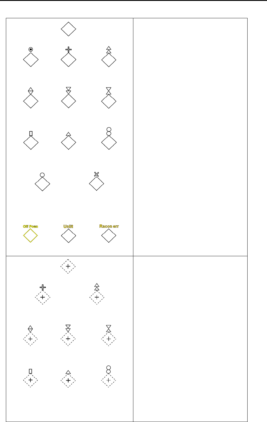
MDC-7000P/7900P Series Chapter 4 Target (AIS,TT and Trial manoeuvre)
0093169006-05E 4-15
Physical AIS AtoN
Virtual AIS AtoN
Basic shape
Racon Emergency
wreck mark
North cardinal
mark
East cardinal
mark
South cardinal
mark
West cardinal
mark
Port hand mark Starboard hand
mark
Isolated dange
r
Safe wate
r
Special mar
k
Off position Lights failure Racon failure
(IALA dictionary, topmarks)
Basic shape
Emergency wreck mark North cardinal mark
East cardinal
mark
South cardinal
mark
West cardinal
mark
Port hand mark Starboard hand
mark Isolated dange
r
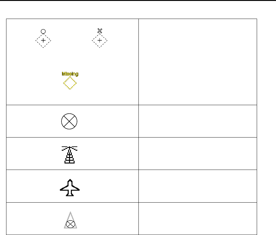
Chapter 4 Target (AIS, TT and Trial manoeuvre) MDC-7000P/7900P Series
0093169006-05E 4-16
AIS –SART
(AIS Search and Rescue Transponder)
BASE
AIS SAR aircraft
AIS SAR vessel
* ID can be displayed with Activated target.
Intended location of missing ATON
Safe wate
r
Special mark
(IALA dictionary, topmarks)

MDC-7000P/7900P Series Chapter 4 Target (AIS,TT and Trial manoeuvre)
0093169006-05E 4-17
4.3 TT (ARPA)
It is an effective mean for collision avoidance by generating vectors on tracked targets.
It is an effective means for collision avoidance to set up CPA/TCPA.
If AIS information is available with tracked targets, association increases tracking accuracy.
Limitations of the TT function
There are the following limitations on use of the target acquisition and tracked target of TT (ARPA)
functions.
Note:
• If multiple targets approach each other, this may cause the system to regard them as one target and
thus to swap them or loss part of them. Such swapping or less of targets may also occur if the picture
of the target being tracked is affected by rain/snow clutter returns or sea clutter returns or moves very
close to land.
• Intensity of echoes and the TT function have a correlation ship, and thus the target will be lost if no
echoes and detected during six scans in succession. If a lost target exists, therefore, radar gain must
be increased to support detection of the target. If radar gain is increased too significantly, sea clutter
returns or other noise may be erroneously detected and tracked as a target, and resultingly, a false
alarm may be issued.
• To execute accurate tracking, it becomes necessary first to appropriately adjust the GAIN, SEA and
RAIN knobs of the radar so that the target to be acquired and tracked id clearly displayed on the radar
display. Inappropriate settings of these adjustments reduce the reliability / accuracy of automatic
tracking.
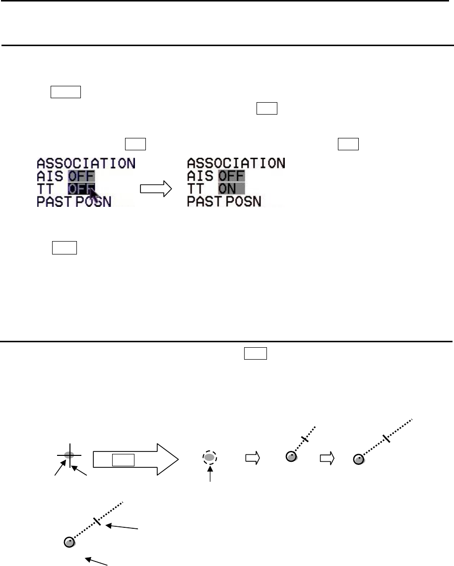
Chapter 4 Target (AIS, TT and Trial manoeuvre) MDC-7000P/7900P Series
0093169006-05E 4-18
Enable TT function
There are two methods to enable TT function.
By menu
1 Press MENU key to display “Menu”.
Select [TARGET] => [TT] => [TT] => [ON], and press ENT key.
By trackball
1 Move cursor on the TT OFF in the upper right of the display, then press ENT key.
Note:
• Pressing ACQ key in [OFF] state automatically turns to [ON] state.
• TT function does not work due to incompleteness of input sentence when own ship information
display in upper right of the display is turned orange.
• TT (ARPA) is effective by using TT in combination with [ASSISTANT DISP].
Manual acquisition
1 Move cursor to a target to be acquired, then press ACQ key.
A broken circle symbol is displayed at the cursor location, and acquisition starts.
About 30sec. from 1min. later, a broken circle symbol turn into a thick solid line, displayed vector of
target’s motion trend and TT ID number (if selected), and displayed within 3min. the target’s
prediction motion.
Target Cursor
ACQ key
Broken circle
1 1
1
TT ID number (1 to 100)
Refer to 4.1 Common setting “Set AIS/TT ID DISP TYPE”
and “Set ID DISP SIZE”.
Time increment marker (OFF, 2, 3, 5, 10)
Refer to 4.1 Common setting “VECTOR REL/TRUE”.
MDC-7000P/7900P Series Chapter 4 Target (AIS,TT and Trial manoeuvre)
0093169006-05E 4-19
Delete TT target
There are two methods to delete TT target. First method is to use menu operation, second is to use
cursor operation.
Menu operation
This is to delete the TT target selected [SELECT ID] and [DELETE] function.
1 Press MENU key to display “Menu”.
Select [TARGET] => [TT] => [SELECT ID] => select ID number, and press ENT key.
Selection values: 1 to 100
2 Select [DELETE], and press ENT key.
Cursor operation
1 Move cursor to a TT (ARPA) target to be deleted, keep OFF key pressed, and then press ACQ
key.
Delete all TT targets
1 Press MENU key to display “Menu”.
Select [TARGET] => [ALL DELETE], and press ENT key.
All TT targets acquisitions are deleted.

Chapter 4 Target (AIS, TT and Trial manoeuvre) MDC-7000P/7900P Series
0093169006-05E 4-20
Reference target acquisition
If SDME or EPFS is not usable due to malfunction or other reason, then COG/SOG can be obtained by
setting Reference target.
By tracking 1 or 2 stationary targets, the true speed course can be used.
This stationary tracked target is called [Reference target].
A letter “R” denoting reference and number are attached to the lower left of Reference target symbol.
Note:
• Reference target can be used only when COG/SOG is not available.
• HDG input is necessary to use a reference target.
• Reference target has considerable error factor caused by target size, backlash and distance.
Accordingly, if COG/SOG is obtained from the reference target, then its accuracy is generally not
good. It is probable to mistake a moving target for a reference target. Therefore, if a reference target
is used, then CPA/TCPA of TT (ARPA), relative vector and relative speed are prohibited by IEC
62388. For this reason, if a reference target is used, its speed and vector should be only informative.
• Pay attention to that, if a reference target is lost, then accuracy of the true speed/the true course is
significantly reduced.
• Select a stationary target as a reference target to calculate own ship speed as ground tracking speed.
Do not choose a moving target as a reference target. A moving produces target error in the vector for
TT and AIS, which results in wrong collision avoidance information. Further, an unstable stationary
target produces inaccurate speed data and the target itself may become lost.
• The combined use with AIS function cannot be performed.
• When a reference target is lost, that reference target mark blinks and the indication “Ref tracked target
is lost” appears in the alarm display area.
• If the target is lost for 20 seconds, then reference target function is considered a lost target. If a lost
target happens, then the numerical indication of COG/SOG becomes XXXX in orange color. Then
stabilization mode automatically changes from ground stabilization to water stabilization.
• Loss of reference target will affect the calculation of true speed and true course of targets. Further,
own ship speed will be inaccurate.
By using menu
1 Move cursor using trackball to the stationary target to be acquired.
2 Press MENU key to display “Menu”.
Select [TARGET] => [TT] => [REF ACQ], and press ENT key.
3 When reference target is tracked, [GYRO] characters in the own ship information area at right side
of the display change to yellow. Move cursor using trackball to the [GYRO] characters, then press
ENT key. [GYRO] characters change to [REF] characters.
COG/SOG computed by the reference target can be used.

MDC-7000P/7900P Series Chapter 4 Target (AIS,TT and Trial manoeuvre)
0093169006-05E 4-21
By without using menu
1 Move cursor using trackball to the stationary target to be acquired, then press ACQ key.
2 Move cursor to the acquired target, then press ENT key.
Acquired target information will be displayed in “TGT INFO” area at side of the display.
3 Move cursor to the REF OFF positon in “TGT INFO” area at side of the display, and [OFF]
characters change to reverse characters.
Press ENT key to set REF target from TT target.
[GYRO] characters in the own ship information area at right side of the display change to yellow.
Move cursor using trackball to the [GYRO] characters, then press ENT key. [GYRO] characters
change to [REF] characters.
COG/SOG computed by the reference target can be used.
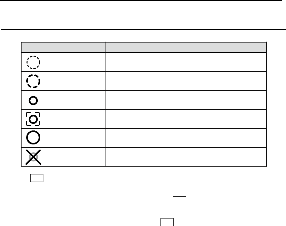
Chapter 4 Target (AIS, TT and Trial manoeuvre) MDC-7000P/7900P Series
0093169006-05E 4-22
Types of tracked target symbol
The following symbols are overlaid on target.
*
**
***
**
**
**
****
Symbol
Blink in
0.5 sec. interval
Blink in
0.5 sec. interval
Symbol name
Radar target in acquisition state
Tracked radar target
Radar target in acquisition state - Automatic acquisition
(Red clolor)
Tracked radar target
(Displayed at indicating numerical value.)
Tracked radar targets - dangerous target
(Red clolor)
Blink in
0.5 sec. interval
Lost target
(Red clolor)
* Pressing OFF key to acknowledge changes of target symbol to normal color and stop blinking.
** ID can be displayed in Tracked target.
*** Alarm display and alarm sound disappear by pressing OFF key to acknowledge, while color
remains red until the target leaves outside of setting range or tracking is stopped.
**** The lost target display disappears automatically when OFF key is pressed to acknowledge or when
10 seconds have passed.
(Red color)
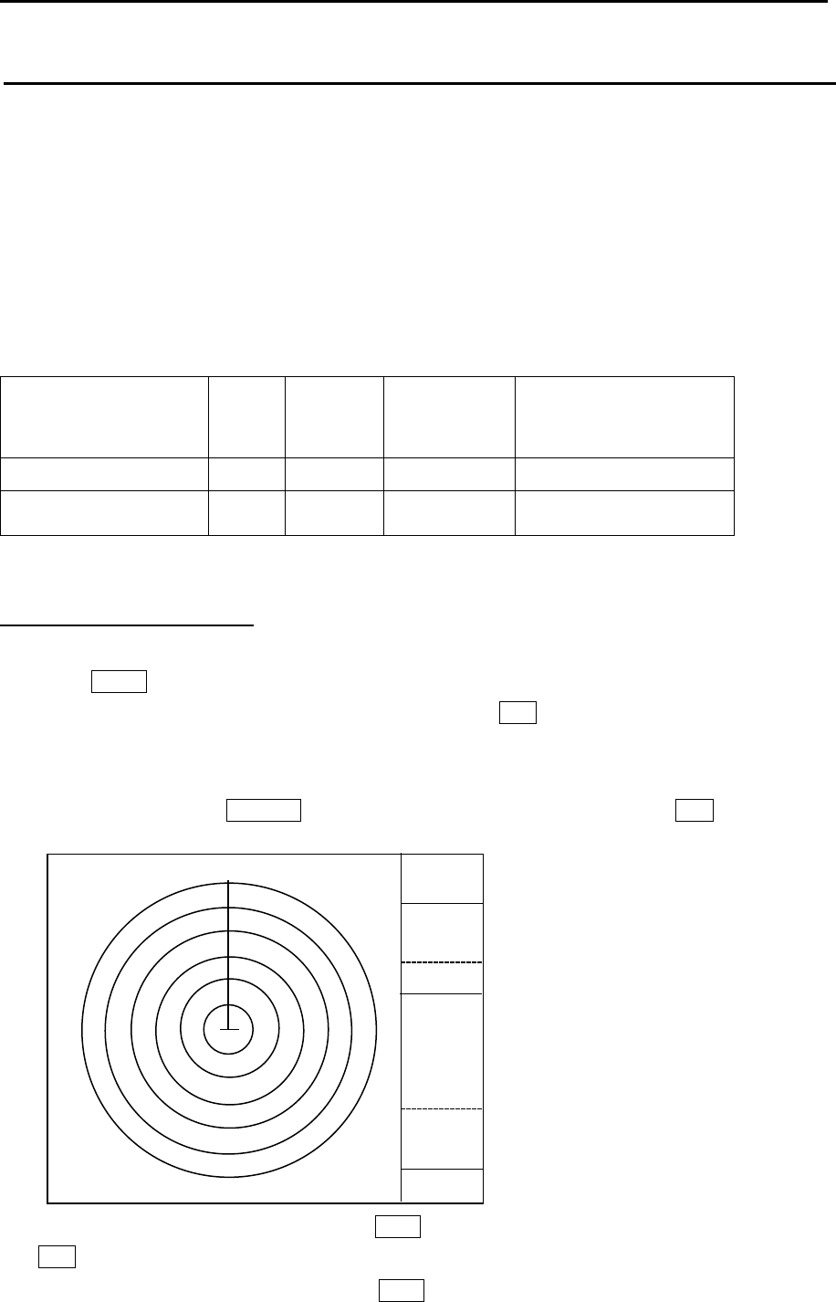
MDC-7000P/7900P Series Chapter 4 Target (AIS,TT and Trial manoeuvre)
0093169006-05E 4-23
TEST TGT
Two types of test are provided.
One is check of TT (ARPA) performance and the other is check of functions.
Note:
• For TEST TGT execution, input of own-ship position is required.
• Time input (ZDA, DTM) is not necessary, but without time input, an alarm will activate periodically.
TT (ARPA) performance check
Confirm that the acquisition and track of target is possible, and that the accuracy of data is within the
specification mentioned below.
Time of steady state
minutes
CPA
NM
TCPA
minutes
True course
Degrees
(°)
True speed
1 min: trend 1.0 – – –
3 min: prediction 0.3 0.5 5
0.5 kn or 1 %
(whichever is greater)
Preparation
Display Range rings as follows.
By menu
1 Press MENU key to display “Menu”.
Select [NAV TOOL] => [RR] => [RR] => [ON], and press ENT key.
By trackball
1 Move cursor on the RR OFF display at upper left of the display, then press ENT key.
2 Set [RAIN] at a minimum level by turning RAIN knob and set [SEA] at a minimum level by turning
SEA knob.
3 Set [GAIN] at a maximum level by turning GAIN knob.
12NM
2NM
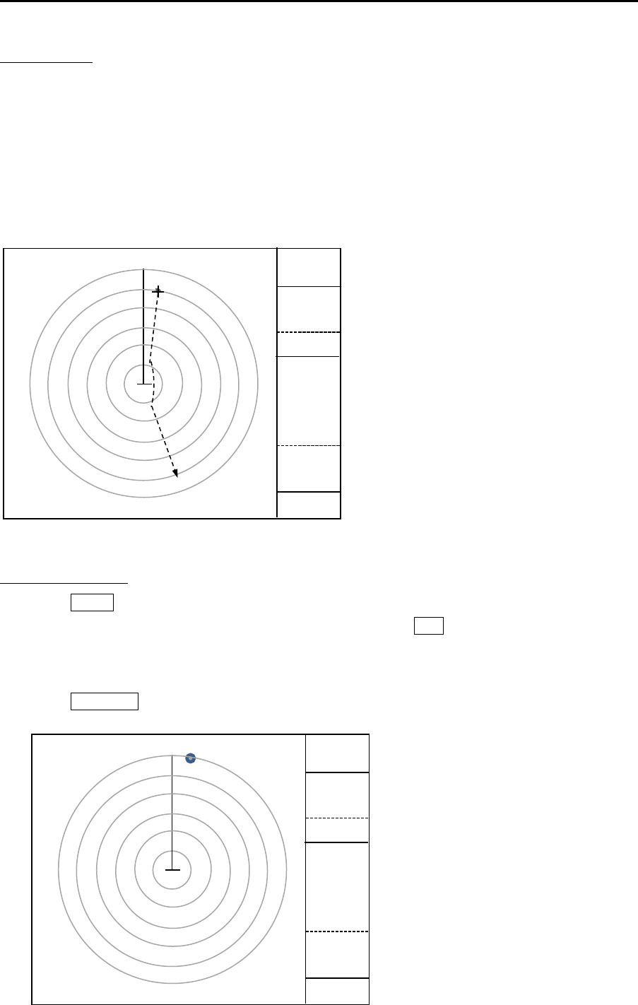
Chapter 4 Target (AIS, TT and Trial manoeuvre) MDC-7000P/7900P Series
0093169006-05E 4-24
TEST TGT ON
By turning TEST TGT [ON], a large character [X] is displayed at the lower middle of the display center.
A small character [x] is displayed in Target position.
Turn on TEST TGT, and start transmission. Then, range scale changes to 12NM automatically, and a
test target appears under the small character [x] position.
A test target appears near the direction 10° and range 12NM. After approaching to own ship, the target
moves toward direction 207°.
Own ship's speed is about 42kn and the test target speed is about 32kn (Relative speed is 74kn).
Turn ON TEST TGT.
1 Press MENU key to display “Menu”.
Select [TARGET] => [TT] => [TEST TGT] => [ON], and press ENT key.
Range scale will change to 12NM automatically.
During [TEST TGT] operation, range scale is fixed at 12 NM and cannot be changed.
2 Press STBY / TX key to start transmission.
X
12NM
2NM
X
12NM
2NM
x
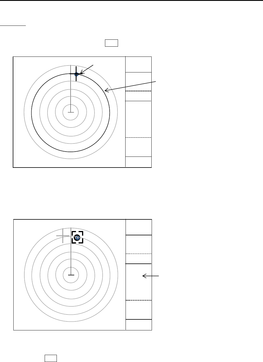
MDC-7000P/7900P Series Chapter 4 Target (AIS,TT and Trial manoeuvre)
0093169006-05E 4-25
Start ACQ
1 After the center of the target reaches to 10NM (the second ring from outside), use a trackball, and
move cursor to the target and press ACQ key.
2 Confirm appearance of the dotted circle of acquisition start symbol and the parenthesis of value
near it.
The values are indicated in “TGT INFO” area.
Note: If the parentheses are not displayed, then drag a cursor to the acquisition start symbol and
press ENT key.
X
12NM
2NM
x
10NM Rangering
Cursor
x
X
12NM
2NM
1
TGTINFO
area
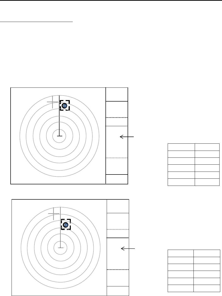
Chapter 4 Target (AIS, TT and Trial manoeuvre) MDC-7000P/7900P Series
0093169006-05E 4-26
Compare it with the known result.
1 Tracking starts 30 seconds after the start of acquisition
Confirm that the target has the tracking symbol.
Confirm that the symbol number is [1].
Note: If the number is not correct, then no comparison with the known result is made. Delete the
symbol and start it over.
2 Compare with the known result after 1 minute from acquisition start
3 Compare with the known result after 3 minutes from acquisition start.
BRG T 11.7°
RNG 8.9NM
CTW 207.0°
STW 31.5kn
CPA 0.01NM
TCPA 7.30min
BRG T 11.7°
RNG 6.5NM
CTW 207.0°
STW 32.0kn
CPA 0.01NM
TCPA 5.20min
x
X
12NM
2NM
1
TGTINFO
area
x
X
12NM
2NM
1
TGTINFO
area

MDC-7000P/7900P Series Chapter 4 Target (AIS,TT and Trial manoeuvre)
0093169006-05E 4-27
Note: If difference from the known result exceeds the limit, then the following warning is indicated in
alarm display are at lower right of the display.
Tracking malfunction. BRG T (Bearing accuracy is degraded)
Tracking malfunction. RNG (Range accuracy is degraded)
Tracking malfunction. CPA (CPA accuracy is degraded)
Tracking malfunction. TCPA (TCPA accuracy is degraded)
Tracking malfunction. T CRS (True course accuracy is degraded)
Tracking malfunction. T SPD (True course accuracy is degraded)
TEST TGT OFF
1 Press MENU key to display “Menu”.
Select [TARGET] => [TT] => [TEST TGT] => [OFF], and press ENT key.
Stop transmission and restore GAIN, RAIN, and SEA setting value of knobs to the original value.
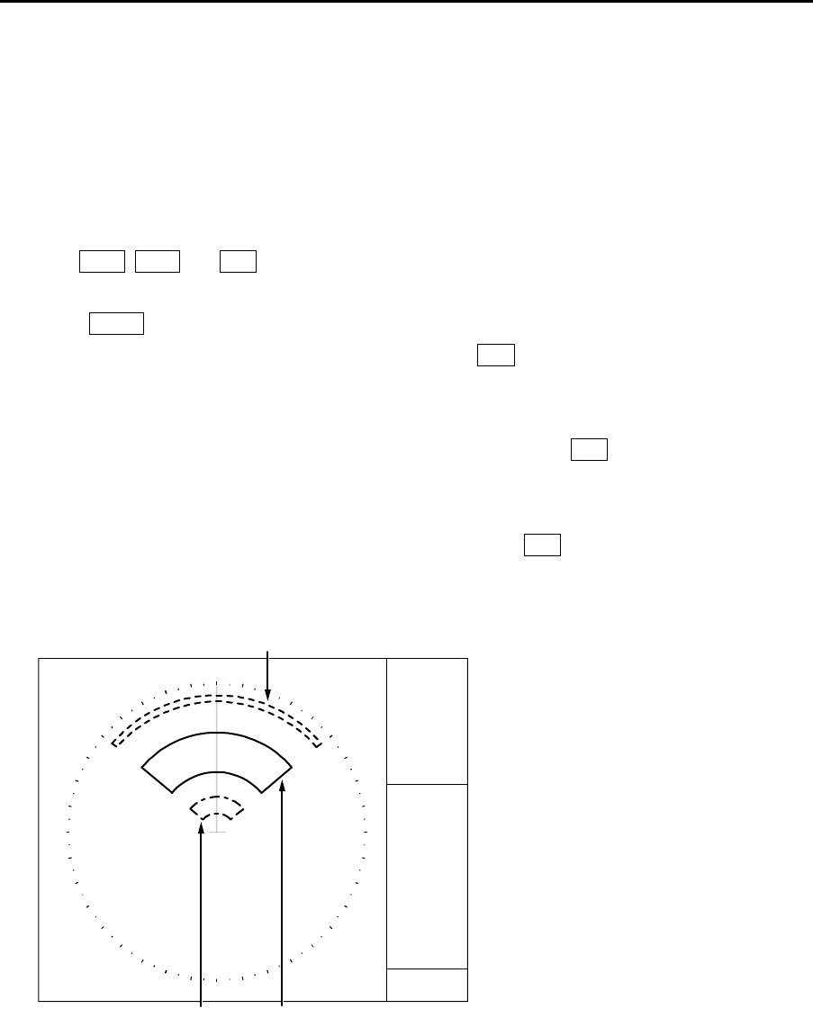
Chapter 4 Target (AIS, TT and Trial manoeuvre) MDC-7000P/7900P Series
0093169006-05E 4-28
Function check
This function is used to confirm the operation of Echo alarm, Manual acquisition TT (ARPA), Auto
acquisition, Past position and Guard zone.
Preparation
1 Set up the range to 12 NM.
2 Turn GAIN, RAIN and SEA knobs and set these levels at a minimum.
3 Set up the echo alarm as follows:
Press MENU key to display “Menu”.
Select [ALARM] => [ECHO ALARM] => [IN], and press ENT key.
Set up the echo alarm range.
4 Set up the Guard zone.
Select [ALARM] => [GUARD ZONE] => [EDIT] => [ON], and press ENT key.
Set up the range of Guard zone.
5 Set up the Auto acquisition.
Select [TARGET] => [AUTO ACQ AREA] => [ON], and press ENT key.
Set up the range of Auto acquisition.
AUTO ACQ AREA (TT, AIS)GUARD ZONE
ECHO
A
LARM
12NM
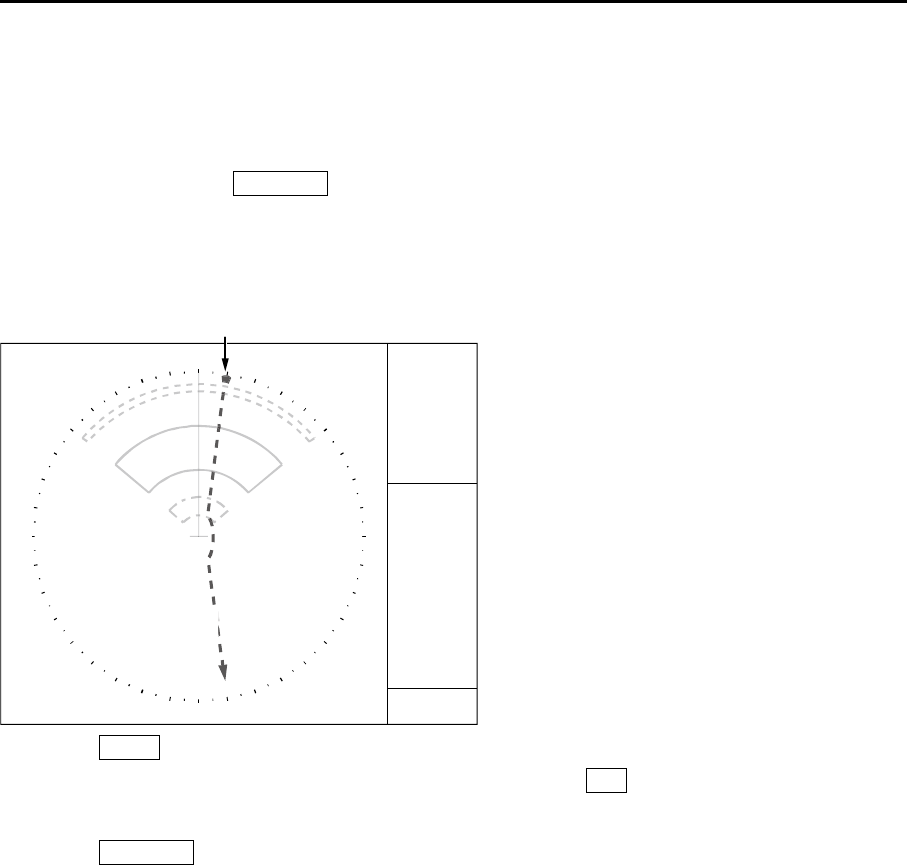
MDC-7000P/7900P Series Chapter 4 Target (AIS,TT and Trial manoeuvre)
0093169006-05E 4-29
TEST TGT ON
By turning TEST TGT [ON], a large character [X] is displayed at the lower middle of the display.
A small character [x] is displayed in Target position.
Turn on TEST TGT, press STBY / TX key, and start transmission. Then, a target appears.
A target appears near the direction 10° and range 12 NM. After approaching to own ship, the target
moves toward direction 207°.
Own ship's speed is about 42 kn and the target speed is about 32 kn (Relative speed is 74 kn).
x
S
Target
12NM
1 Press MENU key to display “Menu”.
Select [TARGET] => [TT] => [TEST TGT] => [ON], and press ENT key.
Range is fixed at 12 NM and cannot be changed.
2 Press STBY / TX key to start transmission.
X
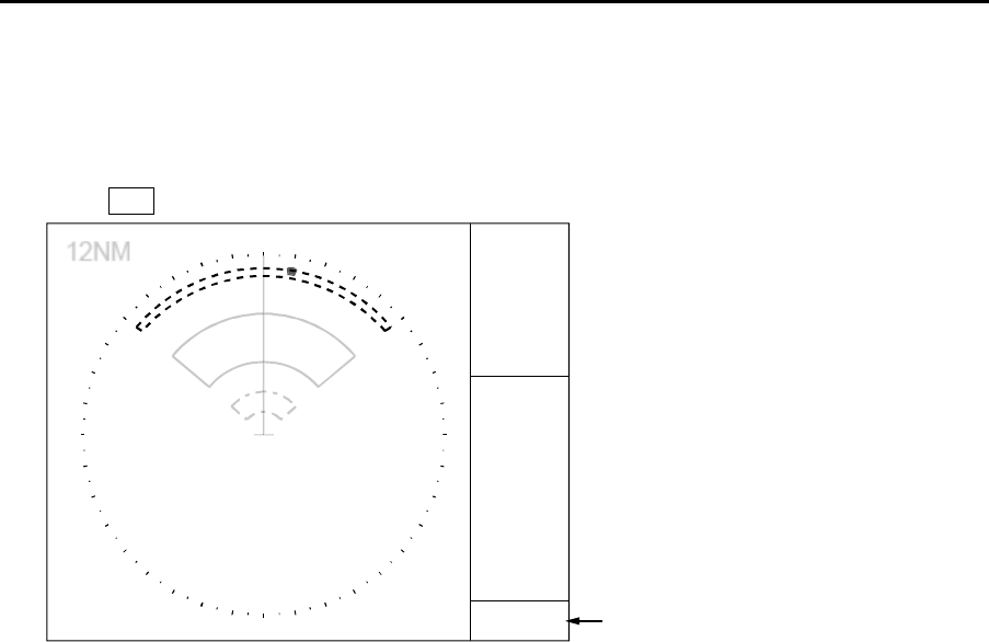
Chapter 4 Target (AIS, TT and Trial manoeuvre) MDC-7000P/7900P Series
0093169006-05E 4-30
Echo alarm
1 Confirm that when the target enters the echo alarm area, the echo alarm is displayed in alarm
display area at the lower right of the display.
Press OFF key to acknowledge. Then, alarm will disappear.
x
Alarm display area
X
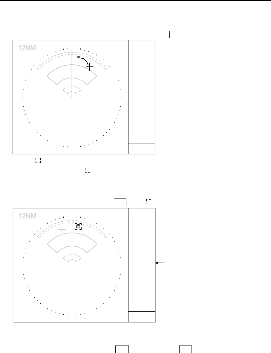
MDC-7000P/7900P Series Chapter 4 Target (AIS,TT and Trial manoeuvre)
0093169006-05E 4-31
Manual acquisition TT (ARPA)
1 Use a trackball to move cursor to the target and press ACQ key.
x
2 Symbol will be displayed by acquisition.
Information of symbol with is displayed in the “TGT INFO” area.
CPA/TCPA are displayed as [missing] until tracking is started.
Move the cursor on symbol and press ENT key, if is not displayed yet.
TGT INFO area
3 Confirm that data is changed from [missing] after the symbol is changed to tracked one.
4 Move the cursor again.
Delete the tracked symbol by pressing ACQ key while keeping OFF key pressed.
X
X
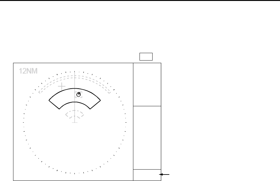
Chapter 4 Target (AIS, TT and Trial manoeuvre) MDC-7000P/7900P Series
0093169006-05E 4-32
Auto acquisition
1 If a target enters the Auto acquisition area and 15 seconds pass, then automatic acquisition starts.
Start of tracking is displayed in the alarm display area at lower right of the display.
Acquired symbol is shown in blinking red until OFF key is pressed to acknowledge.
Alarm display area
X
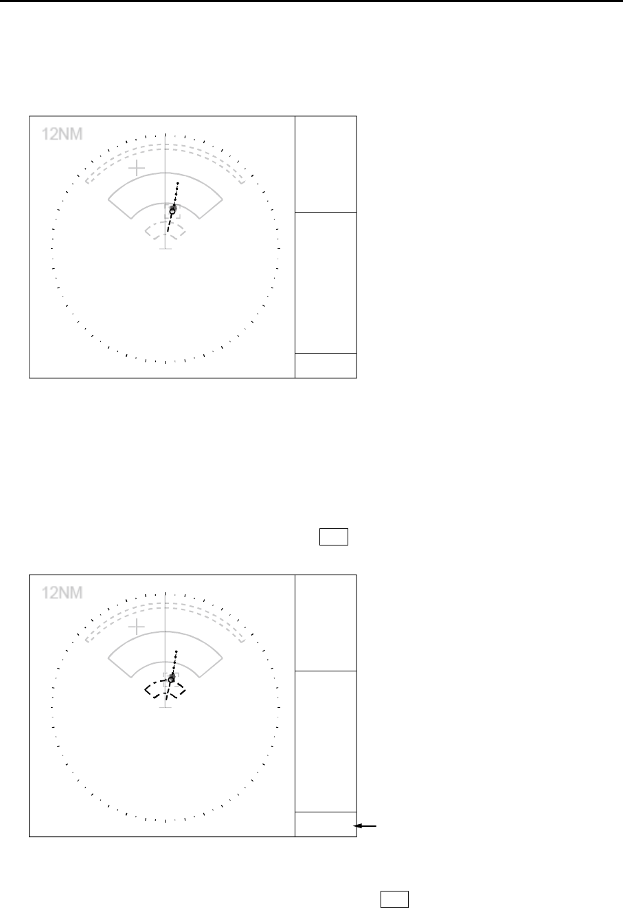
MDC-7000P/7900P Series Chapter 4 Target (AIS,TT and Trial manoeuvre)
0093169006-05E 4-33
Past position
1 Trail of tracked symbol is displayed by setting past position time.
Set up the past position time in the “PAST POSN” at the right middle of the display.
PAST POSN 3min
Guard zone
1 Confirm that the Guard zone alarm is displayed in the alarm display area at the lower right of the
display when the tracked symbol has entered the Guard zone.
Blinking of tracked symbol will stop by pressing OFF key to acknowledge.
The tracked symbol remains red until it leaves from Guard zone.
Alarm display area
TEST TGT OFF
Select [TARGET] => [TT] => [TEST TGT] => [OFF], and press ENT key.
Stop transmission and restore GAIN, RAIN, and SEA setting value to original knob position.
X
X
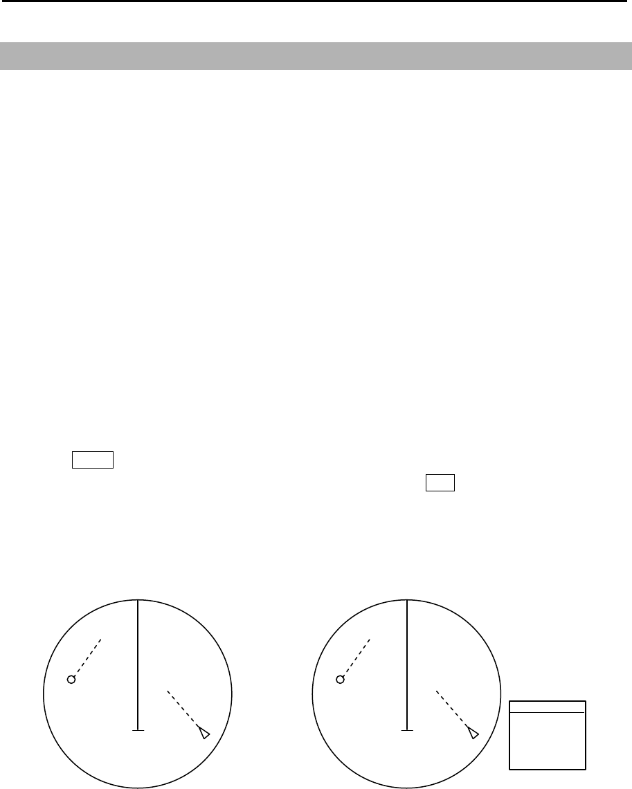
Chapter 4 Target (AIS, TT and Trial manoeuvre) MDC-7000P/7900P Series
0093169006-05E 4-34
T
4.4 Trial manoeuvre
In case it is suspected the own ship could collide with tracked targets or activated AIS targets, this
function provides such reference information as the actual anti-collision manoeuvre can be taken. This
function is to display the simulation result in the form of graphic vector on the radar display, on the
assumption that the own ship travels with the current course and speed.
Assuming that the own ship and other ships (tracked targets and activated AIS targets) are both
concurrently moving at the present course and speed [CRS·SPD] for the duration set at [DELAY],
vector is displayed in such a way that the own ship is to move at the set [CRS T], [SPD], [RATE OF
TURN] and [RATE OF SPD] from the starting point.
Note:
• Better information is provided by using relative motion and sea stabilization (water tracking).
• The function is terminated once the HDG input, SPD input, LAT/LON input (AIS only) are disrupted, as
tracked targets and activated AIS targets are used.
1 Press MENU key to display “Menu”.
Select [TARGET] => [TRIAL MANOEUVRE] => [GO], and press ENT key.
2 By turning TRIAL MANOEUVRE [GO], a large character [T] is displayed at the lower center of the
display and the setting menu of TRIAL MANOEUVRE is displayed at the lower right of the display.
TRIAL MANOEUVRE
TRIAL
CRS T
SPD
DELAY
RATE OF TURN
RATE OF SPD
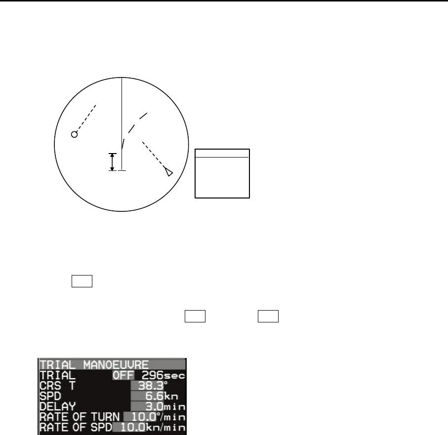
MDC-7000P/7900P Series Chapter 4 Target (AIS,TT and Trial manoeuvre)
0093169006-05E 4-35
In addition, the movement of the own ship and the other ships is displayed in vector after elapse of
the time set at [DELAY] of TRIAL MANOEUVRE setting menu.
3 TRIAL MANOEUVRE setting menu
Each numerical value in the grey background color area is set by user. Move the cursor to the grey
area, press ENT key, and a numerical value input dialogue box will appear. The value of the dialog
box can be set by the trackball.
For [TRIAL OFF], moved the cursor OFF and press ENT key, TRIAL MANOEUVRE is finished
immediately.
TRIAL: OFF
When the trial manoeuvre commences, count down starts from 300 seconds and ends at 0
second. When you decide to stop the function during the countdown, select the countdown
display and set OFF.
CRS T: This indicates own ship’s course after [DELAY].
SPD: This indicates own ship’s speed after [DELAY].
DELAY: This indicates the starting time of TRIAL MANOEUVRE. After the time set, the own ship
starts moving at [CRS T], [SPD], [RATE OF TURN], [RATE OF SPD].
RATE OF TURN: This indicates own ship’s rate of turn after [DELAY].
RATE OF SPD: This indicates own ship’s acceleration rate after [DELAY].
DELAY
T
TRIAL MANOEUVRE
TRIAL
CRS T
SPD
DELAY
RATE OF TURN
RATE OF SPD
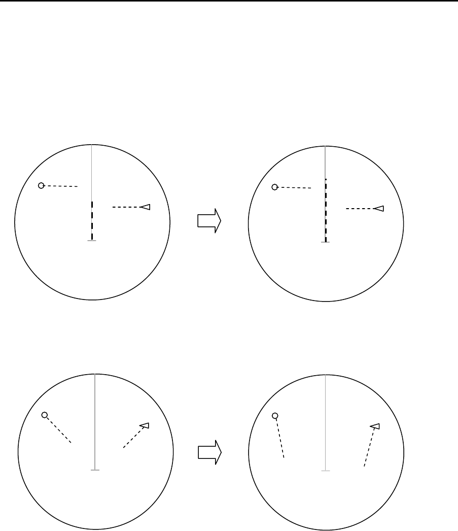
Chapter 4 Target (AIS, TT and Trial manoeuvre) MDC-7000P/7900P Series
0093169006-05E 4-36
4 When setting is done for [CRS T], [SPD], [RATE OF TURN], [RATE OF SPD], own ship’s vector
will change when the vector setting is [VECT T] and the other ship’s vector will change when
vector setting is [VECT REL].
[TRUE VECTOR when own ship’s speed is doubled]
[RELATIVE VECTOR when own ship’s speed is doubled]
T
V
ECT T
T
V
ECT T
T
VECT REL
T
VECT REL
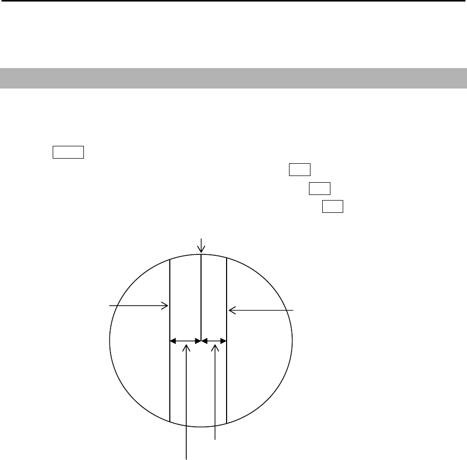
MDC-7000P/7900P Series Chapter 5 Nav tool
0093169006-05E 5-1
Chapter 5 Nav tool
5.1 Guard line
Guard line function is a function that displays parallel lines to the heading on both side of own ship.
Distance to guard line from own ship can be set from 0 to 10000m (left and right side independently).
1 Press MENU key to display “Menu”.
Select [NAV TOOL] => [GUARD LINE] => [ON], and press ENT key.
2 Select [LEFT] => set left side distance 0 to 10000m, and press ENT key.
3 Select [RIGHT] => set right side distance 0 to 10000m, and press ENT key.
Right side guard line
Left side guard line
Right side distance
Left side distance
Heading line
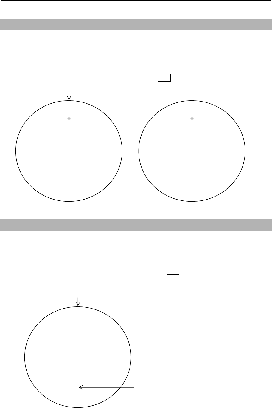
Chapter 5 Nav tool MDC-7000P/7900P Series
0093169006-05E 5-2
5.2 HL blink
HL BLINK function lets HL marker display blinks every antenna rotation. It is effective to confirm that
there is no small targets right under the HL marker.
1 Press MENU key to display “Menu”.
Select [NAV TOOL] => [HL BLINK] => [ON], and press ENT key.
5.3 Stern line
STERN LINE is to set up the display of dotted line extended from reference position to bearing scale
toward stern direction.
1 Press MENU key to display “Menu”.
Select [NAV TOOL] => [STERN LINE] => [ON], and press ENT key.
Heading line
Heading line
Stern line
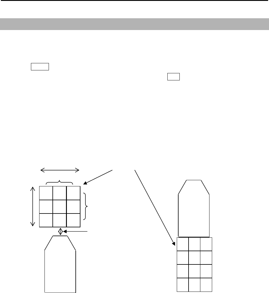
MDC-7000P/7900P Series Chapter 5 Nav tool
0093169006-05E 5-3
5.4 Barge icon
This radar is equipped with a barge icon feature that is very helpful for river operation where user can
set up the size dimensions of the tow and be able to display it on the display.
1 Press MENU key to display “Menu”.
Select [NAV TOOL] => [BARGE ICON] => [ON], and press ENT key.
2 Select and set [POSITION], [LENGTH], [WIDTH], [LINE NO.], [ROW NO.], [OFFSET]
POSITION: FWD, AFT
LENGTH: 0m to 511m
WIDTH: 0m to 511m
LINE NO.: 1 to 10
ROW NO.: 1 to 10
OFFSET: 0m to 511m
Length
Width
Line number
Row number
Offset
OS outline
Barge icon
OS outline
Forward positon After position
Line: 3
Row: 2
Offset: 0
- This page intentionally left blank.-
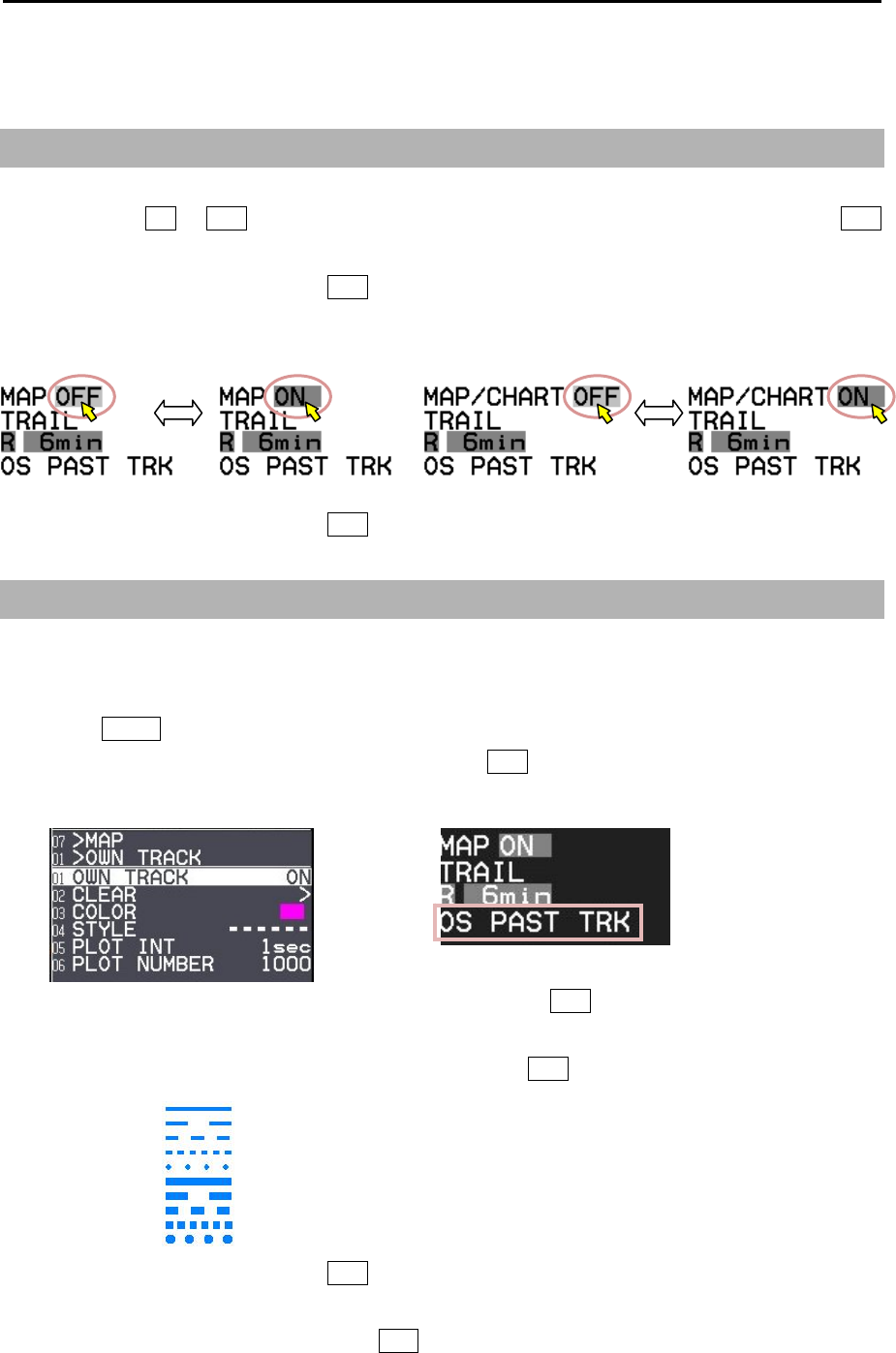
MDC-7000P/7900P Series Chapter 6 Map operation
0093169006-05E 6-1
Chapter 6 Map operation
6.1 MAP function display ON or OFF
This is to turn ON/OFF the entire MAP function.
Select the MAP ON or OFF box at the lower left corner of the display using trackball and press ENT
key. (To display CHART, select [MAP] => [CHART] => [ON].)
It is not displayed as well as HL while OFF key is pressed.
This operation links the functions, COAST LINE, NAV LINE, ROUTE, EVENT MKR and AREA. In case
CHART is “ON”, CHART display is linked to this operation.
It is not displayed as well as HL while OFF key is pressed.
6.2 OWN SHIP PAST TRACK
This is to set up OWN SHIP PAST TRACK display, function on or off, clear operation, color setting, plot
style, plot interval and maximum plot numbers.
1 Press MENU key to display “Menu”.
Select [MAP] => [OWN TRACK] => [ON] and press ENT key.
[OS PAST TRK] message will appear at the lower left of the display, and displays past track line.
2 Select [COLOR] => select color from eight colors => press ENT key.
PAST TRACK will turn selected color.
3 Select [STYLE] => select past t rack line style* => press ENT key.
4 Select [PLOT INT] => and press ENT key after selecting the set up value.
Selection values: 1sec, 2sec, 5sec, 10sec, 30sec, 1min, 3min
5 Select [PLOT NUMBER] => and press ENT key after selecting the set up value.
Selection values: 1000, 2000, 4000, 5000, 7000, 10000, 20000
*Line style:
CHART [OFF] CHART [ON]
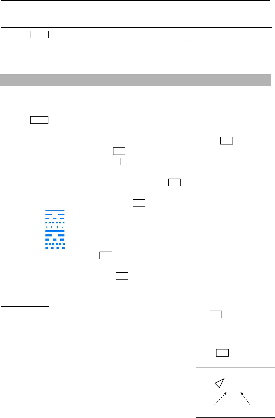
Chapter 6 Map operation MDC-7000P/7900P Series
0093169006-05E 6-2
How to Clear OWN SHIP PAST TRACK
1 Press MENU key to display “Menu”.
Select [MAP] => [OWN TRACK] => [CLEAR] => [GO], and press ENT key.
All OWN SHIP PAST TRACK disappears, recording and display will restart.
6.3 Target track past position display
This is to set up TT past track position display, display ON or OFF, clear operation, color setting, select
track style, plot interval and maximum plot numbers.
1 Press MENU key to display “Menu”.
Select [MAP] => [TARGET TRACK] =>
2 Select [TARGET TRACK] => turn trackball to right, select [1 to 100], and press ENT key.
3 Select [DISPLAY] => [ON], and press ENT key.
4 Select [CLEAR] => [GO], and press ENT key.
The past track of chosen TT will be deleted.
5 Select [COLOR] => select color from eight colors => press ENT key.
TT past track will turn selected color.
6 Select [STYLE] => select line style* => press ENT key.
7 Select [PLOT INT] => and press ENT key after selecting the set up value.
Selection values: OFF, 2sec, 15sec, 30sec, 1min, 3min, 5min
8 Select [PLOT NUMBER] => and press ENT key after selecting the set up value.
Selection values: 50, 100, 200, 500, 1000
Target track start
1 Move cursor to an AIS target or TT (ARPA) target to display track, keep ENT key pressed, and
then press ACQ key.
Target track finish
1 Move cursor to an AIS target or TT (ARPA) target to track off, and then press OFF key.
Note: TARGET TRACK ID and numbers are displayed at the lower right
of AIS or TT (ARPA) target.
Above ID and numbers are not displayed when [NUMBER] of
[AIS ID DISP TYPE] / [TT ID DISP TYPE] setting is [OFF].
(Refer to 4.1 Common setting “Set TT ID DISP TYPE” or
“Set ID DISP SIZE”.)
125 / 2
ID Numbe
r
Target Track
Numbe
r
<Exam
p
le: AIS>
*Line style:
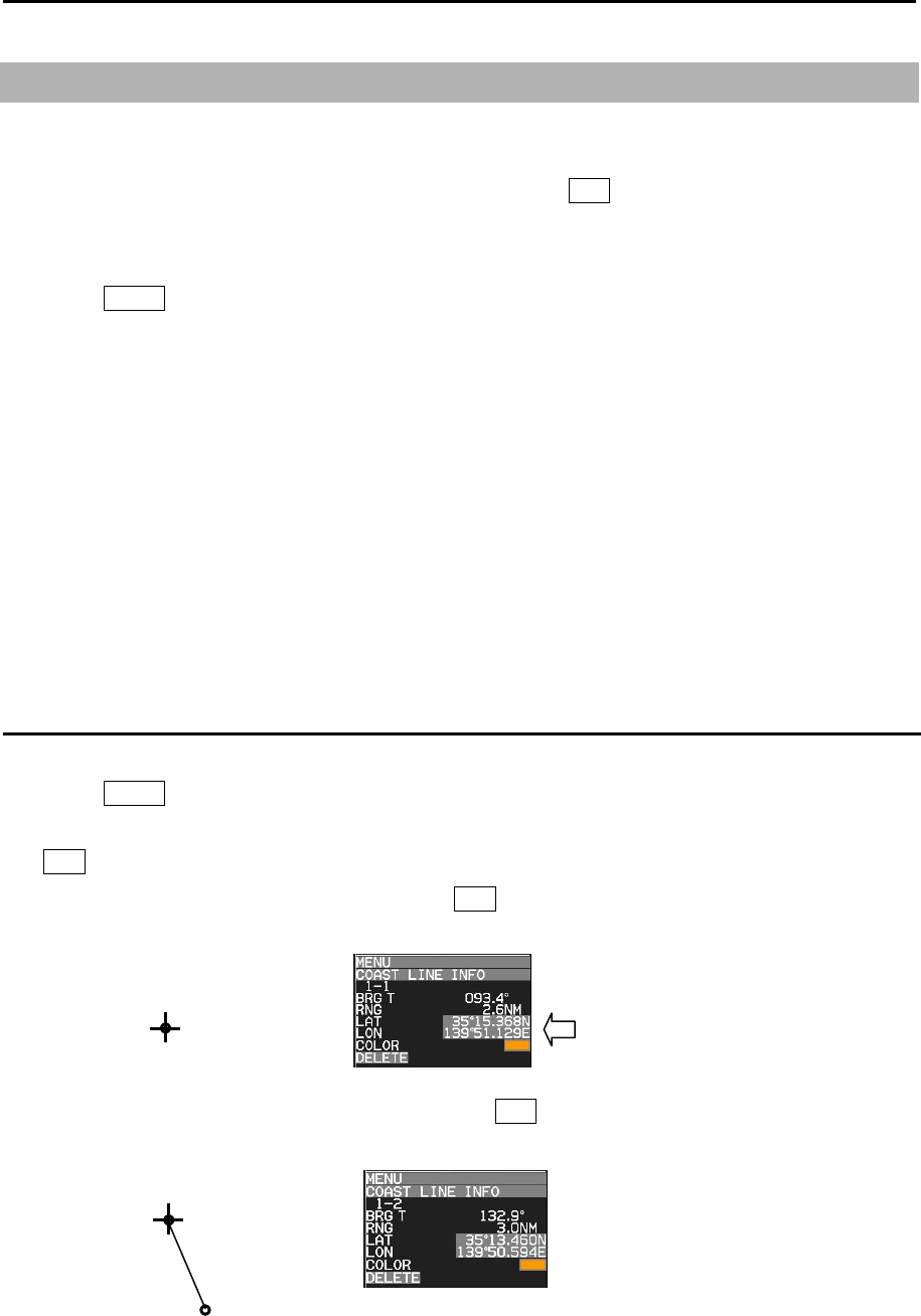
MDC-7000P/7900P Series Chapter 6 Map operation
0093169006-05E 6-3
6.4 COAST LINE
This function is to let user generate up to 10 coast lines with up to 100 points each to mark important
areas of navigation, such as danger zone areas or navigation channels etc. Coast line can be setup by
inputting Lat/Lon information for each point or using cursor and ENT key.
It is displayed one by one or all.
1 Press MENU key to display “Menu”.
Select [MAP] => [COAST LINE] =>
COAST LINE: Select the number of the coast line to display. (ALL, 1 to 10, OFF)
ALL: Display all ten coast line.
1 to 10: Display the coast line of selected number.
OFF: Don’t display coast line.
EDIT: Create coast line. (CURSOR, BLOCK NUMBER)
MOVE: Change the position. (CURSOR, BLOCK NUMBER)
ADD: Insert a position data. (CURSOR, BLOCK NUMBER)
DELETE: Delete a position data. (CURSOR, BLOCK NUMBER)
CLEAR: Clear a selected block number coast line data.
How to edit
(1) CURSOR OPERATION
1 Press MENU key to display “Menu”.
Select [MAP] => [COAST LINE] => [EDIT] => [CURSOR] => select [1 to 10] => [GO] and press
ENT key.
2 Move cursor to first input position, then press ENT key. No.1 mark is displayed on the display and
numerical data is shown at coast line info area.
3 Move cursor to second input position, then press ENT key. No.2 mark is displayed, and a line is
generated from No.1 to No.2.
Edit of LAT/LON data, color setting
and delete function can be operated
directly using cursor with trackball in
this info area.
x-1
x-2
x-1
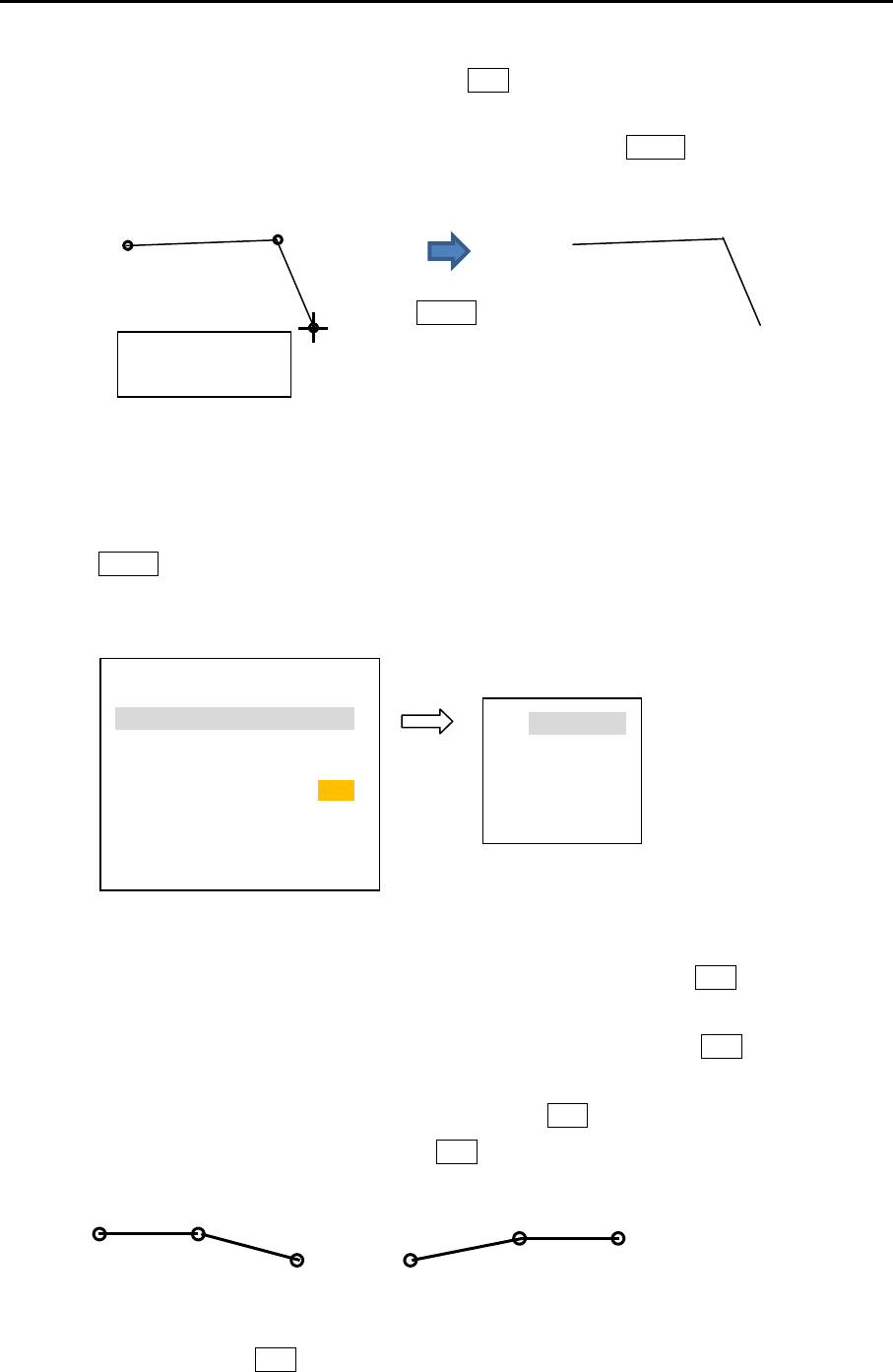
Chapter 6 Map operation MDC-7000P/7900P Series
0093169006-05E 6-4
4 Move cursor to third input position, then press ENT key. No.3 mark is displayed, and a line is
generated from No.2 to No.3.
You can input up to 100 point. When input is completed, press MENU key. Mark number will
disappear.
5 Refer to 3.4 Nav line cross “How to edit” for the procedures to make plural divided coast line in the
memory of same block number.
(2) BLOCK NUMBER OPERATION
1 Press MENU key to display “Menu”.
Select [MAP] => [COAST LINE] => [EDIT] => [BLOCK NUMBER] => select [1 to 10] =>
Following input menu is displayed.
2 Select [LAT] => Latitude data set screen is displayed.
Set LAT data by moving of trackball to the right, left, up or down, and press ENT key.
3 Select [LON] => Longitude data set screen is displayed.
Set LON data by moving of trackball to the right, left, up or down, and press ENT key.
4 Select [COLOR] => Eight colors box is displayed.
Select color by moving of trackball up or down, and press ENT key.
5 Select [DIVIDE] => [ON] or [OFF], and press ENT key.
[DIVIDE] => [ON] means that it is not connected coast line to the next number data.
6 Select [SET], and press ENT key to save input data.
NUMBER 1
LAT 0˚ 00.000N
LON 0˚ 00.000E
COLOR
DIVIDE OFF
SET
0˚ 00.000N
0˚ 00.000N
90˚ 00.000S-
90˚00.000N
1- 1-2
1-3
DIV IDE
ON
1-4
1-5 1-6
1-1
x: Block number
(1 to 10)
Press
MENU key
x-3
x-1 x-2
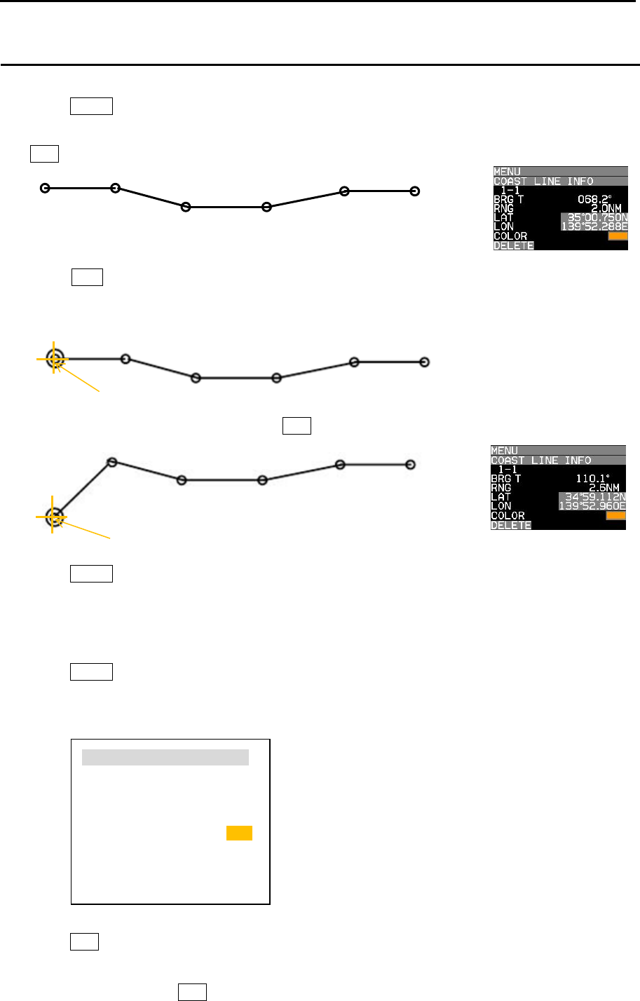
MDC-7000P/7900P Series Chapter 6 Map operation
0093169006-05E 6-5
1-1 1-2
1-3 1-4
1-5 1-6
1-1
1-2
1-3 1-4
1-5 1-6
Cur s or
1-1
1-2
1-3 1-4
1-5 1-6
Cur s or
How to move
(1) CURSOR OPERATION
1 Press MENU key to display “Menu”.
Select [MAP] => [COAST LINE] => [MOVE] => [CURSOR] => select [1 to 10] => [GO], and press
ENT key. Numerical number is displayed each points of coast line.
2 Move cursor on editing and moving cursor data.
Press ACQ key. Circle mark will be displayed on the selected coast line and numerical data is
shown at coast line info area.
3 Move cursor to new position, then press ENT key.
4 Press MENU key to exit MOVE operation.
(2) BLOCK NUMBER OPERATION
1 Press MENU key to display “Menu”.
Select [MAP] => [COAST LINE] => [MOVE] => [BLOCK NUMBER] => select [1 to 10] =>
Following input menu is displayed.
2 Select [NUMBER] => NUMBER data screen is displayed. => select [1 to 100] =>
Press ENT key. Selected number’s numerical data is shown.
3 Edit data of LAT, LON, COLOR and DIVIDE.
4 Select [SET] and press ENT key to save input data.
NUMBER 1
LAT 35˚ 15.368N
LON 139˚ 51.129E
COLOR
DIVIDE OFF
SET
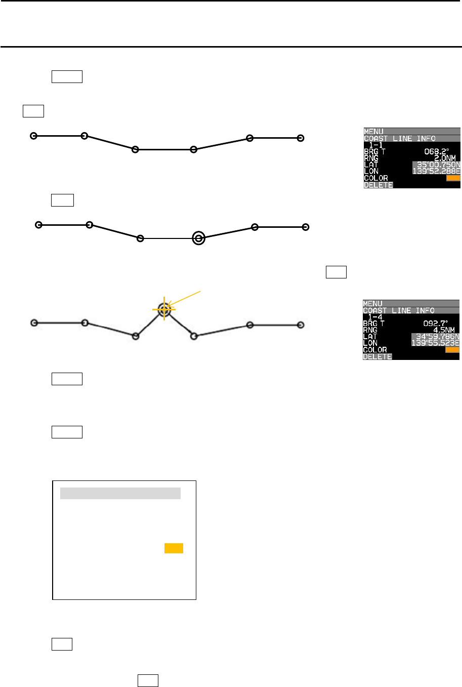
Chapter 6 Map operation MDC-7000P/7900P Series
0093169006-05E 6-6
1-1 1-2
1-3 1-4
1-5 1-6
1-1 1-2
1-3 1-4
1-5 1-6
Cur s or
1-4
1-1 1-2
1-3 1-5
1-6 1-7
How to add
(1) CURSOR OPERATION
1 Press MENU key to display “Menu”.
Select [MAP] => [COAST LINE] => [ADD] => [CURSOR] => select [1 to 10] => [GO] and press
ENT key. Numerical number is displayed each points of coast line.
2 Move cursor on position that new data is added in just before it.
Press ACQ key. Circle mark will be displayed on the selected.
3 Move cursor to the position that new data will be added, then press ENT key.
4 Press MENU key to exit ADD operation.
(2) BLOCK NUMBER OPERATION
1 Press MENU key to display “Menu”.
Select [MAP] => [COAST LINE] => [ADD] => [BLOCK NUMBER] => select [1 to 10] =>
Following input menu is displayed.
2 Select [NUMBER] => NUMBER data screen is displayed. => select [1 to 100] =>
Press ENT key. Selected number’s numerical data is shown.
3 Edit data of LAT, LON, COLOR and DIVIDE.
4 Select [SET] and press ENT key to save input data. New data is added as same as cursor
operation.
NUMBER 4
LAT 35˚ 15.368N
LON 139˚ 51.129E
COLOR
DIVIDE OFF
SET
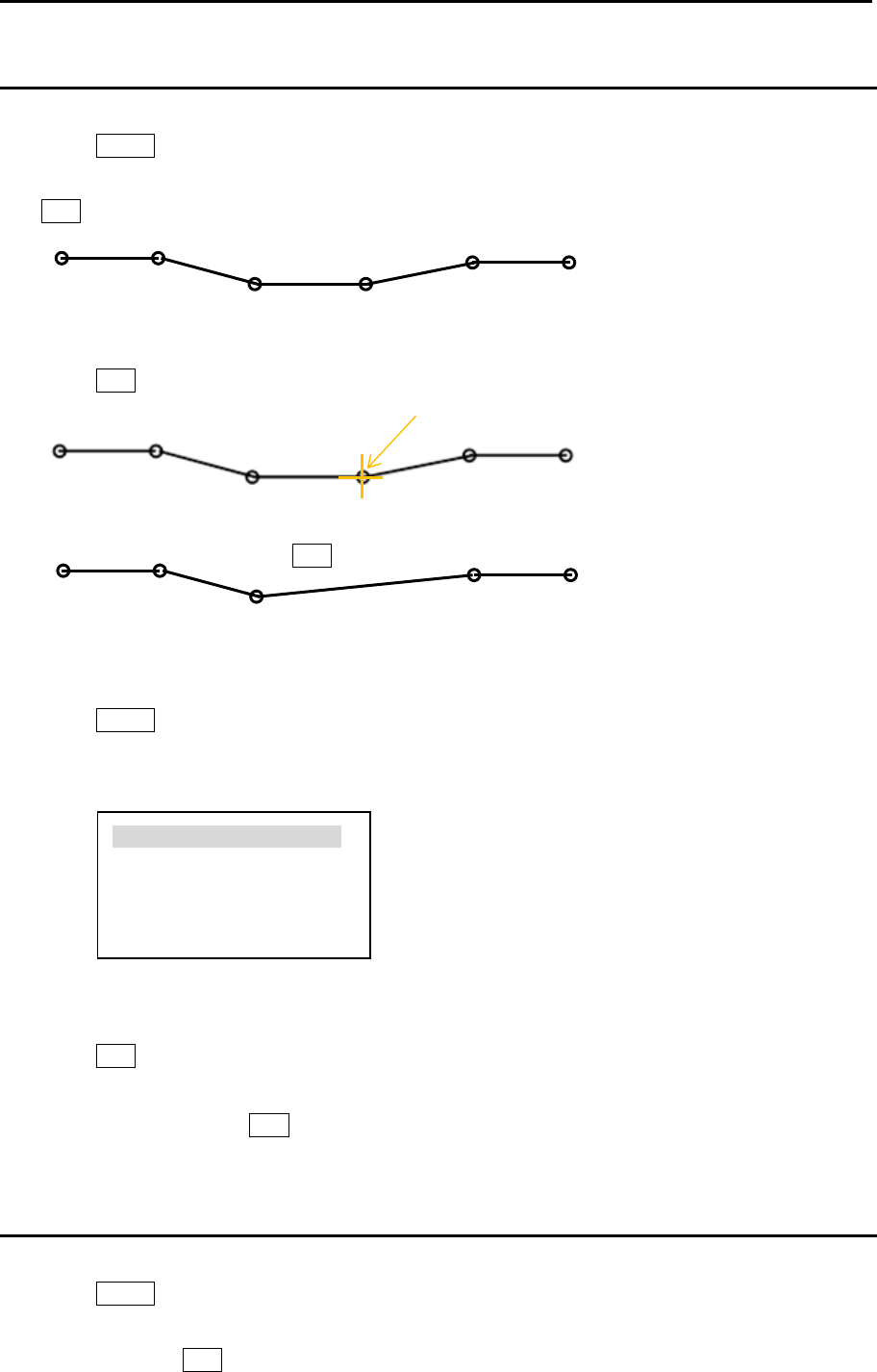
MDC-7000P/7900P Series Chapter 6 Map operation
0093169006-05E 6-7
1-1 1-2
1-3 1-4
1-5 1-6
1-1 1-2
1-3
1-4 1-5
1-1 1-2
1-3 1-4
1-5 1-6
Cur s or
Press
ENT key
How to delete
(1) CURSOR OPERATION
1 Press MENU key to display “Menu”.
Select [MAP] => [COAST LINE] => [DELETE] => [CURSOR] => select [1 to 10] => [GO] and press
ENT key. Numerical number is displayed each points of coast line.
2 Move cursor on the position deleting.
Press ENT key. Selected coast line data will be deleted.
(2) BLOCK NUMBER OPERATION
1 Press MENU key to display “Menu”.
Select [MAP] => [COAST LINE] => [DELETE] => [BLOCK NUMBER] => select [1 to 10] =>
Following delete menu is displayed.
2 Select [NUMBER] => NUMBER data screen is displayed. => select [1 to 100] =>
Press ENT key. Selected number’s numerical data is shown.
3 Select [SET], and press ENT key to delete selected data.
How to clear
All data of selected block number are cleared.
1 Press MENU key to display “Menu”.
Select [MAP] => [COAST LINE] => [CLEAR] => [BLOCK NUMBER] => select [1 to 10] => select
[GO], and press ENT key.
NUMBER 4
LAT 35˚ 15.368N
LON 139˚ 51.129E
SET

Chapter 6 Map operation MDC-7000P/7900P Series
0093169006-05E 6-8
6.5 NAV LINE
NAV LINE is a function to display Navigation line by inputting Lat/Lon information for each point or
using cursor and ENT key to input the points, user can set 10 lines up to 100 points each.
“NAV LINE” generated in this section can also be used in the alarm function for “NAV LINE CROSS”
alarm.
Refer to 3.4 Nav line cross.
1 Press MENU key to display “Menu”.
Select [MAP] => [NAV LINE] =>
NAV LINE: Select the number of the nav line to display. (ALL, 1 to 10, OFF)
EDIT: Make nav line. (CURSOR, BLOCK NUMBER)
MOVE: Revise the position of the nav line. (CURSOR, BLOCK NUMBER)
ADD: Add a point data in a nav line. (CURSOR, BLOCK NUMBER)
DELETE: Delete a point data in a nav line. (CURSOR, BLOCK NUMBER)
CLEAR: Clear selected block number nav line data.
NAV LINE operation is same as 3.4 Nav line cross and 6.4 COAST LINE operation.
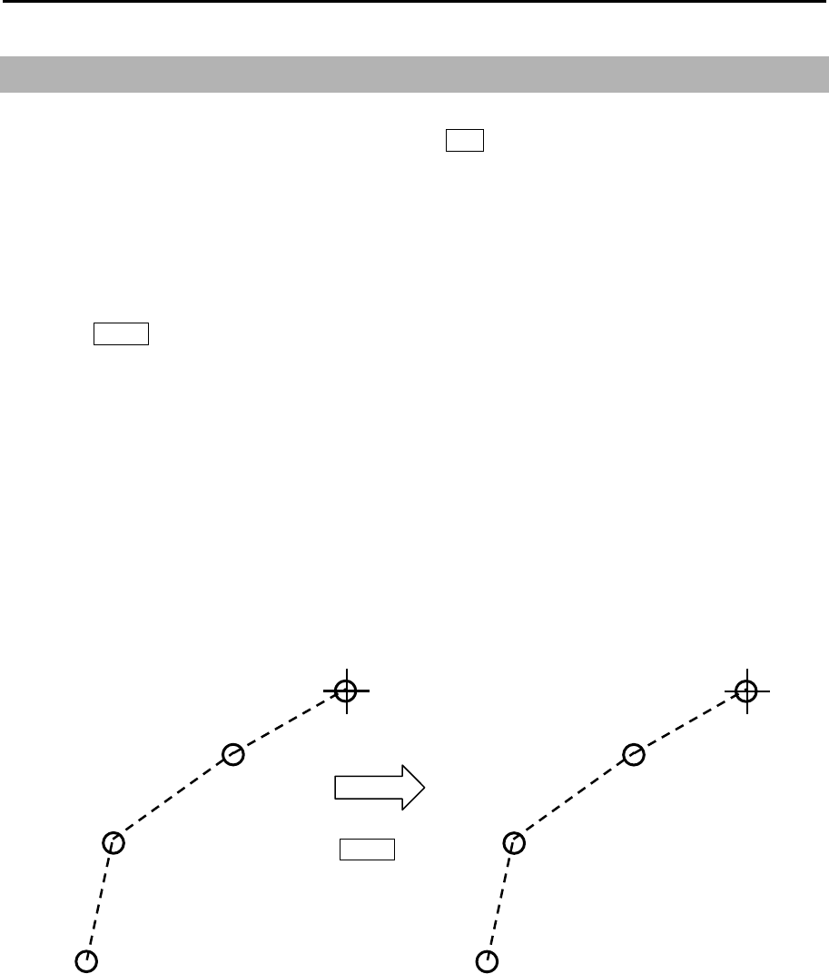
MDC-7000P/7900P Series Chapter 6 Map operation
0093169006-05E 6-9
6.6 ROUTE
The ROUTE function is for display purposes only, user can setup ROUTE on radar display for visual
navigation aid. ROUTE can be setup using cursor and ENT key or by inputting Lat/Lon information for
each point. User can add 10 routes with up to 100 points each by using below procedure.
Note: If WPT ID DISP in MAP menu is set to “OFF” then route waypoint name information will not be
displayed, and if set to “ON” all waypoints on the route will have name information displayed next
to them.
1 Press MENU key to display “Menu”.
Select [MAP] => [ROUTE] =>
ROUTE: Select the number of the route to display. (ALL, 1 to 10, OFF)
EDIT: Make route. (CURSOR, BLOCK NUMBER)
MOVE: Revise route position. (CURSOR, BLOCK NUMBER)
ADD: Add a point to a route. (CURSOR, BLOCK NUMBER)
DELETE: Delete a point from a route. (CURSOR, BLOCK NUMBER)
CLEAR: Clear selected block number route.
ROUTE operation is same as COAST LINE operation.
x-1
x-2
x-3
x-4
Press
MENU key

Chapter 6 Map operation MDC-7000P/7900P Series
0093169006-05E 6-10
6.7 EVENT MKR
EVENT MKR function displays various marks on the designated place, and can utilize it for sign, such
as a destination, a fishery and a caution area. EVENT MKR set can be done by input of Lat/Lon
information or by cursor and ENT key.
There are 10 blocks that can store 100 marks in each block.
Below procedure is to operate [EVENT MKR] menu.
1 Press MENU key to display “Menu”.
Select [MAP] => [EVENT MKR] =>
EVENT MKR: Select the number of the event mark to display. (ALL, 1 to 10, OFF)
EDIT: Input event mark. (CURSOR, BLOCK NUMBER)
MOVE: Revise position of an event mark. (CURSOR, BLOCK NUMBER)
ADD: Add an event mark. (CURSOR, BLOCK NUMBER)
DELETE: Function to delete event mark using cursor and ENT key or BLOCK NUMBER.
CLEAR: Clear all event marks in a given memory block.
User can designate function key such as [F1]-[F6] to [EVENT CURSOR] or [EVENT OWN] for quick
shortcut to input [EVENT MKR].
Refer to 2.21 Function key usage.
When set [EVENT MKR] by using function key operation, this radar can output Lat/Lon data of EVENT
MKR to external device.
It is necessary to set the output port to output [EVENT MKR] data to external device, following
[MAINTENANCE] menu must be set.
Note: This menu is protected in normal. To cancel the protection, refer to 1.3 Menu usage “Display
[MAINTENANCE] menu”.
1 Press MENU key to display “Menu”.
Select [MAINTENANCE] => [I/O] => [OUTPUT] => [TLL OUT] => [MARK], and press ENT key.
2 Select [MAINTENANCE] => [I/O] => [OUTPUT] =>
Select [OUTPUT PORT from NAV, EPFS, SDME, GYRO and OTHER] that is connected to
external device.
3 Select [TLL] => set time to [0.1 to 10.0 sec (except 0.0 sec)], and press ENT key.
When press function key (EVENT CURSOR or EVENT OWN), this radar outputs the Lat/Lon data
of EVENT by $RATLL sentence.

MDC-7000P/7900P Series Chapter 6 Map operation
0093169006-05E 6-11
6.8 AREA
Area function is for visual navigation where user can input points connected by a line to help with
navigation. There are 10 memory blocks for area that can hold up to 100 points each. This function is
valid with a minimum input of 3 points which will be connected with a line.
It is possible to use AREA to set alarm for targets entering or leaving the area.
Refer to 3.2 Map area alarm.
1 Press MENU key to display “Menu”.
Select [MAP] => [AREA] =>
AREA: Select the block number to display. (ALL, 1 to 10, OFF)
EDIT: To create new area. (CURSOR, BLOCK NUMBER)
MOVE: Revise the position of points in area. (CURSOR, BLOCK NUMBER)
ADD: Add a point to any given position in an area line. (CURSOR, BLOCK NUMBER)
DELETE: Delete a point data in area. (CURSOR, BLOCK NUMBER)
CLEAR: Clear selected block number area data
AREA operation is same as COAST LINE operation.

Chapter 6 Map operation MDC-7000P/7900P Series
0093169006-05E 6-12
6.9 MONITORED ROUTE
This function when activated can display ROUTE information from external device such as chart plotter
or GPS navigator.
RTE + WPL sentences are required from external device to display ROUTE information.
RMB or BWC sentence when inputted from external device will display waypoint information only.
If [RTE + WPL] and [RMB] or [BWC] are inputted in the radar, the ROUTE [RTE + WPL] information
takes priority over [RMB] or [BWC] waypoint information.
Route is displayed by dotted line in orange color.
1 Press MENU key to display “Menu”.
Select [MAP] => [MONITORED ROUTE] => [ON], and press ENT key.
6.10 WPT ID DISP
This function when activated can display WPT name information from external device such as chart
plotter or GPS navigator. This applies to all waypoints from WPT and also ROUTE waypoints. When
[WPT ID DISP] turned on, ID information will be displayed next to waypoints and when turned off only
waypoints without ID information will be displayed.
1 Press MENU key to display “Menu”.
Select [MAP] => [WPT ID DISP] => [ON], and press ENT key.
6.11 TARGET TRACK ID
When tracking a target and past target track is activated, each track will have a label number
associated with it, to turn the numbers “on” or “off” use TARGET TRACK ID and the numbers will
disappear or reappear.
1 Press MENU key to display “Menu”.
Select [MAP] => [TARGET TRACK ID] => [ON], and press ENT key.
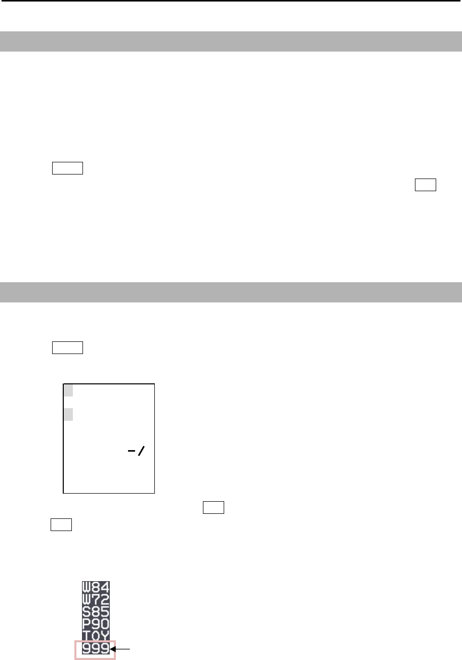
MDC-7000P/7900P Series Chapter 6 Map operation
0093169006-05E 6-13
999
1234567890
ABCDEFGH I J
KLMNOPQRST
UV
W
XYZ+ ?
DEL
EX I T SPACE
←→
6.12 DATUM
Local geodetic datum and datum offsets from a reference datum. This is used to define the datum to
which a position location and geographic locations are referenced. Latitude, Longitude and altitude
offsets from the reference datum, and the selection of the referenced datum is provided in following
menu.
This is to set up DATUM code.
1 Press MENU key to display “Menu”.
Select [MAP] => [DATUM] => select [W84], [W72], [S85], [P90], [TOY], [999], and press ENT key.
[999] is a user datum. In some special cases and or areas specific datum should be entered
therefore please use user datum and edit it for that specific datum. User datum can be setup by
following “EDIT USER DATUM” menu.
6.13 EDIT USER DATUM
In case that user specific datum needs to be entered, then use below procedure to set the name.
1 Press MENU key to display “Menu”.
Select [MAP] => [EDIT USER DATUM] => [DATUM] data input window will appear.
2 Select each letter one by one and press ENT key after each letter, when finished select [EXIT] and
press ENT key.
The three letters of [999] in the [DATUM] menu change to the edited letters.
The [999] changes to edited letters.
Chapter 6 Map operation MDC-7000P/7900P Series
0093169006-05E 6-14
6.14 POSITION OFFSET
This is to select OFFSET input of position.
Selection values: EPFS, MAN
1 Press MENU key to display “Menu”.
Select [MAP] => [OFFSET] => select [EPFS] or [MAN], and press ENT key.
POSITION MANUAL OFFSET
LAT/LON position offset values input is available only when [MAN] of [POSITION OFFSET] menu is
selected.
1 Press MENU key to display “Menu”.
Select [MAP] => [MAN OFFSET] => input offset value of latitude/longitude separately => and
press ENT key.
Selection values: 1.000S to 1.000N
1.000W to 1.000E
MDC-7000P/7900P Series Chapter 6 Map operation
0093169006-05E 6-15
6.15 GPS BUOY
GPS BUOY, of which display is connected to a GPS BUOY’s transmitter-receiver made by Taiyo Musen,
will receive buoy information sentences (BLV).
A buoy ID can record 10 kinds of information, and time, position and water temperature at 100 points
can be recorded per 1 ID. As for the latest data, in addition to time, position and water temperature,
course, speed and battery voltage can be recorded.
Examples of display:
1
24.2
55
0.0
99
-3.3
23.8
0.6
-8.3
22.4
0.8
-12.3
Buoys with same ID will be displayed linked with straight lines. Under each buoy symbol, water
temperature can be indicated.
The latest data will be indicated with marked-out symbols, and ID can be also indicated at the right
hand side of the symbol as shown in the above examples.
1. NUM DISP
This is the function to display Buoy IDs at the right sides of the latest data buoy symbols.
2. WAT TEMP DISP
This is the function to display water temperature under the buoy symbols.
3. BLOCK NUMBER
This is the function to select block numbers. 1 ID buoy data can be recorded in 1 block.
The following 4 ~ 6 will be applied to the blocks selected in above 3.
4. BLOCK CLEAR
This is the function to deleted buoy data recorded in blocks.
5. BLOCK DATA
This is the function to confirm buoy data in blocks in a list of data.

Chapter 6 Map operation MDC-7000P/7900P Series
0093169006-05E 6-16
6.16 WPT FLAG
This function is related to MONITORED ROUTE function. When route or waypoint is inputted from
external device flag will be shown of first waypoint, when route and waypoint information is inputted the
first waypoint on a route takes priority and flag is displayed. Follow below procedure to turn [WPT
FLAG] on and off
1 Press MENU key to display “Menu”.
Select [MAP] => [WPT FLAG] => select [ON] or [OFF], and press ENT key.
6.17 LAT/LON LINE
LAT/LON LINE is a function which when enabled displays geographical latitude and longitude lines on
the radar display. Follow below procedure to turn LAT/LON LINE on and off.
1 Press MENU key to display “Menu”.
Select [MAP] => [LAT/LON LINE] => select [ON] or [OFF], and press ENT key.
6.18 C-MAP chart display
This radar can display chart of C-MAP. The CHART and CHART DISP SET menu are displayed when
C-MAP chart of SD-card type has been inserted in the lower card reader on the rear of the Display unit.
Chart on/off
1 Press MENU key to display “Menu”.
Select [MAP] => [CHART] => select [ON] or [OFF], and press ENT key.
Setting of the detailed chart display
1 Press MENU key to display “Menu”.
Select [MAP] => [CHART DISP SET] => select item of detailed setting, and select [ON] or [OFF]
=> press ENT key.
Setting item: LAND FILL, PLACE NAME, LIGHTHOUSE, BUOY, FISH HAVEN/WRECK,
TRAFFIC ROUTES, CAITION AREA, FISHERY, CABLE
Note: C-MAP chart data is non official chart data.
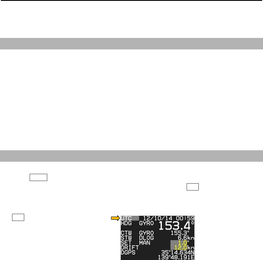
MDC-7000P/7900P Series Chapter 7 System and Maintenance menu operation
0093169006-05E 7-1
Chapter 7 System and Maintenance menu operation
7.1 SYSTEM MENU
INTER-SWITCH: Refer to 2.31 Inter-switch.
TIME
USER
SOUND
HELP
PROTECT MENU: Refer to 1.3 Menu usage.
MON: Refer to 2.33 Performance monitor.
7.2 Change UTC / LOCAL time
1 Press MENU key to display “Menu”.
Select [SYSTEM] => [TIME] => select [UTC] or [LOCAL], and press ENT key.
[UTC / LOCAL] time can be changed directly at the upper right of the own ship data area, with trackball
and ENT key, without using menu.
Note: Refer to [MAINTENANCE] => [I/O] => [TIME] menu for detailed how to set time.
(This menu is protected in normal. To cancel the protection, refer to 1.3 Menu usage “Display
[MAINTENANCE] menu”.)
Chapter 7 System and Maintenance menu operation MDC-7000P/7900P Series
0093169006-05E 7-2
7.3 User memory
This radar is equipped with four user memory slots. All functions and settings can be memorized in the
user memory slots and names can be edited individually.
Change USER memory
1 Press MENU key to display “Menu”.
Select [SYSTEM] => [USER] => select new user memory [1 name to 4 name] => [GO], and press
ENT key.
How to save to memory
All operations are automatically saved in selected user memory slot in real time as they take place so
no action is required from user to save settings.
Edit User Name
The used user memory’s name can be changed by next operation.
1 Press MENU key to display “Menu”.
Select [SYSTEM] => [USER] => [EDIT USER NAME] =>
2 Edit user name window will appear and can change user name.
Maximum 10 letters or numbers can be set for the name.
After name has been changed, press ENT key to save setting.
Default User setting
Using these steps it is possible to clear all data associated with currently selected user.
To delete all user settings and return to default, follow below procedure.
1 Press MENU key to display “Menu”.
Select [SYSTEM] => [USER] => [DEFAULT SETTING] => [GO], and press ENT key.
This operation will clear all information stored in current user memory.

MDC-7000P/7900P Series Chapter 7 System and Maintenance menu operation
0093169006-05E 7-3
7.4 Sound setting
Sound menu is to turn sound ON/OFF, setup frequency of sound in Operation unit, key click sound and
external buzzer.
Sound ON/OFF
1 Press MENU key to display “Menu”.
Select [SYSTEM] => [SOUND] => [SOUND] => select [ON] or [OFF], and press ENT key.
Sound frequency
1 Press MENU key to display “Menu”.
Select [SYSTEM] => [SOUND] => [FREQUENCY] => select [1 to 8], and press ENT key.
Selection values: 1 to 8
1: Lowest frequency
8: Highest frequency
Key click ON/OFF
1 Press MENU key to display “Menu”.
Select [SYSTEM] => [SOUND] => [KEY CLICK] => select [ON] or [OFF], and press ENT key.
External buzzer setting
External buzzer signal (Failure alarm) can be output from J1 connector on the back panel.
Output signal is relay contact. (Alarm contact will open in case of failure.)
Output of relay contact is continuous when set to continue.
Output of relay contact is intermittent when set to interval.
1 Press MENU key to display “Menu”.
Select [SYSTEM] => [SOUND] => [EXT BUZZER] => select [OFF], [CONTINUE] or [INTERVAL],
and press ENT key.
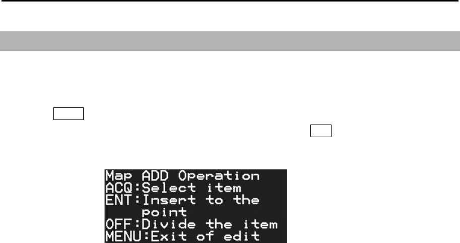
Chapter 7 System and Maintenance menu operation MDC-7000P/7900P Series
0093169006-05E 7-4
7.5 HELP window ON/OFF
Help window is displayed at the lower right of the display. When the help window menu is on, it displays
a procedure of complicated operation such as ALARM and MAP.
1 Press MENU key to display “Menu”.
Select [SYSTEM] => [HELP] => select [ON] or [OFF], and press ENT key.

MDC-7000P/7900P Series Chapter 7 System and Maintenance menu operation
0093169006-05E 7-5
7.6 MAINTENANCE MENU
STARTUP: Refer to 4.2 STARTUP menu of Installation manual.
I/O: Refer to 4.3 Setup I/O Interface of Installation manual.
SECTOR MUTE: Refer to 4.4 Setup SECTOR MUTE mode of Installation manual.
PRESET: Refer to 4.5 Setup PRESET of Installation manual.
BACKUP:
BITE: Refer to Chapter 9 Simple fault diagnosis.
TOTAL HOUR:
TX HOUR:
MENU SETUP:
PASSWORD: Refer to 1.3 Menu usage.
MON: Refer to 2.33 Performance monitor.
VERSION:
7.7 BACKUP of Setup data (Cannot be used while transmitting)
By saving setup data to the internal memory or external memory, the initial setup and all settings are
saved, in the event that the radar needs to be reinitialized or some setup changes been made, user can
go back to the original settings by restoring from memory.
Backup of setup data should be saved after initial setup.
In case of malfunction of display where re-initialization must be done, restore of backup data completed
at the time of original setup will bring all proper settings and tuning setup back to normal operation.
Internal save of setup data
Note: This menu is protected in normal. To cancel the protection, refer to 1.3 Menu usage “Display
[MAINTENANCE] menu”.
To save data internally at the time of setup,
1 Press MENU key to display “Menu”.
Select [MAINTENANCE] => [BACKUP] => [SETUP SAVE] => [GO], and press ENT key.
To restore from internally backup after re-initialization,
1 Press MENU key to display “Menu”.
Select [MAINTENANCE] => [BACKUP] => [SETUP LOAD] => [GO], and press ENT key.

Chapter 7 System and Maintenance menu operation MDC-7000P/7900P Series
0093169006-05E 7-6
External save of setup data (Cannot be performed while transmitting)
To save setup data externally, this information can be later used to restore after a possible malfunction.
The external memory uses an SD memory card.
CAUTION: Please do not use the SD memory card which is loaded with software program files.
Note: This menu is protected in normal. To cancel the protection, refer to 1.3 Menu usage “Display
[MAINTENANCE] menu”.
To perform external backup to SD card,
1 Insert SD memory card in the upper card reader on the rear of the Display unit.
2 Press MENU key to display “Menu”.
Select [MAINTENANCE] => [BACKUP] => [SD CARD] => select [SETUP SAVE], [MARK SAVE],
[TGT TRACK SAVE] or [OWN TRACK SAVE] => [CANCEL] or [GO], and press ENT key.
When SD memory card not inserted, [SD CARD] menu is greyed out and cannot be operated.
To restore from SD card backup after re-initialization,
1 Insert SD card that was used to store settings in above procedure in the upper card reader on the
rear of the Display unit.
2 Press MENU key to display “Menu”.
Select [MAINTENANCE] => [BACKUP] => [SD CARD] => select [SETUP LOAD], [MARK LOAD],
[TGT TRACK LOAD] or [OWN TRACK LOAD] => [CANCEL] or [GO], and press ENT key.
When SD memory card not inserted or no data found on the card, [SD CARD] menu is greyed out
and cannot be operated.
Parameter reset
Use this function as means to return the radar to its default settings as it was at first power on.
Note: This menu is protected in normal. To cancel the protection, refer to 1.3 Menu usage “Display
[MAINTENANCE] menu”.
1 Press MENU key to display “Menu”.
Select [MAINTENANCE] => [BACKUP] => [PARAMETER RESET] => [RESET], and press ENT
key.
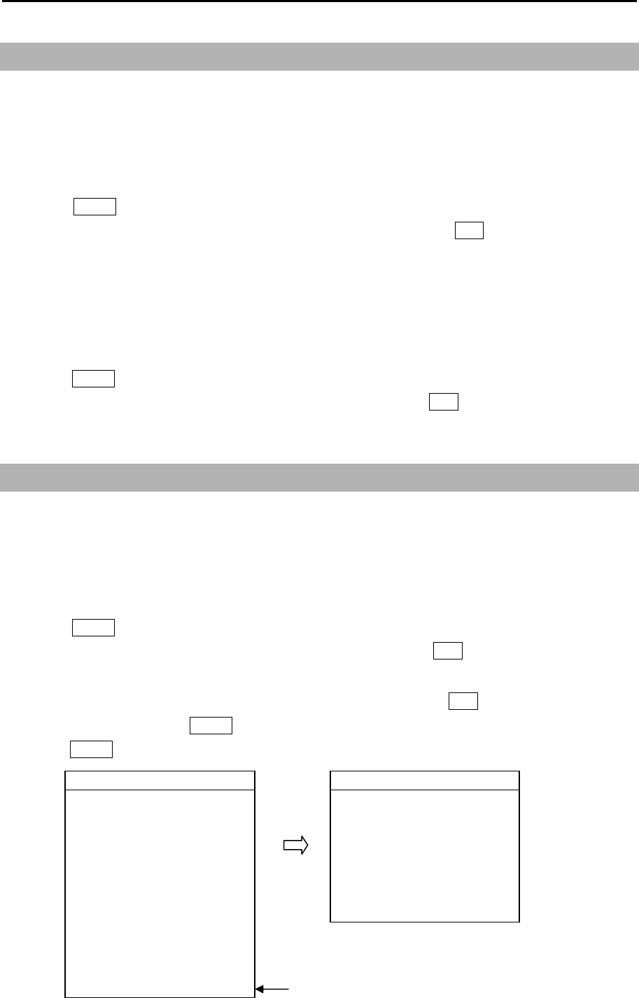
MDC-7000P/7900P Series Chapter 7 System and Maintenance menu operation
0093169006-05E 7-7
7.8 TOTAL HOUR and TX HOUR (Cannot be used while transmitting)
Note: This menu is protected in normal. To cancel the protection, refer to 1.3 Menu usage “Display
[MAINTENANCE] menu”.
TOTAL HOUR menu indicates the total operating time of the radar.
This menu can reset total hour to 0.
1 Press MENU key to display “Menu”.
Select [MAINTENANCE] => [TOTAL HOUR] => [RESET], and press ENT key.
TX HOUR menu indicates the total transmitting time of the radar.
This is useful information to use when exchanging radar parts. Use this hour information to judge
magnetron life expectancy.
Reset after components have been exchanged
1 Press MENU key to display “Menu”.
Select [MAINTENANCE] => [TX HOUR] => [RESET], and press ENT key.
7.9 MENU SETUP
Note: This menu is protected in normal. To cancel the protection, refer to 1.3 Menu usage “Display
[MAINTENANCE] menu”.
MENU SETUP menu can be used to simplify full menu and turn off the items in full menu that are not
used. This is often used to remove not needed menu items for simple operation of the radar.
1 Press MENU key to display “Menu”.
Select [MAINTENANCE] => [MENU SETUP] => [GO], and press ENT key.
Setup menu display will display.
2 Select menu item to set ON or OFF => select [X] or [○], and press ENT key.
3 When setup finish, press MENU key. Menu display will disappear.
Press MENU key again. [X] mark menu items are not displayed.
>ECHO >ECHO
PICTURE MODE ×IR OFF
PROCESS ×VIDEO CONTRAST 3
EXPANSION ×NOISE REJ OFF
IR ○COLOR REJ OFF
VIDEO CONTRAST ○PULSE WIDTH >
NOISE REJ ○SART OFF
COLOR REJ ○PICTURE RESET >
PULSE WIDTH ○
SART ○
PICTURE RESET ○
>ECHO ○
When set [>ECHO] to [x], all ECHO menu
items will not be available.
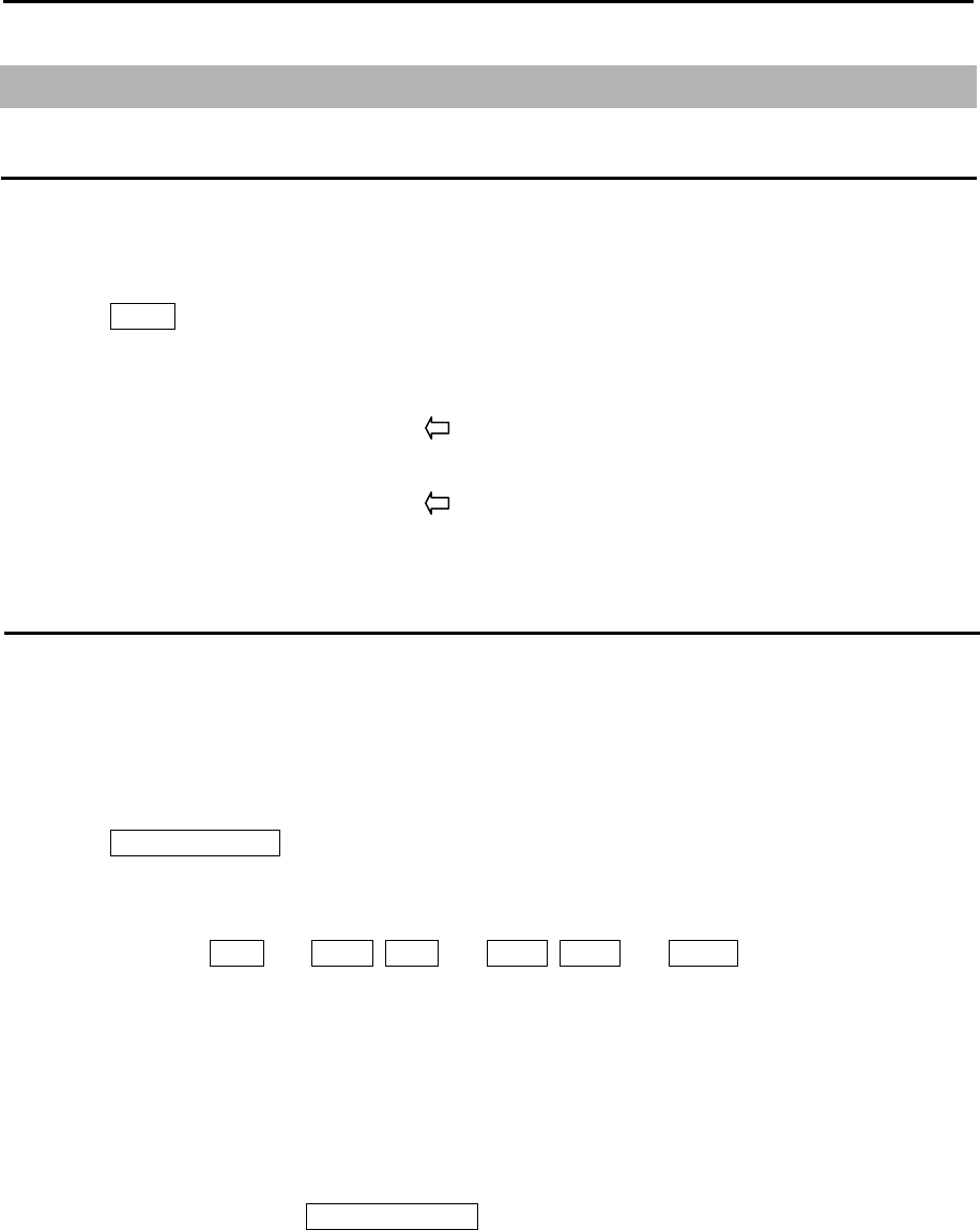
Chapter 7 System and Maintenance menu operation MDC-7000P/7900P Series
0093169006-05E 7-8
7.10 System Program
Version confirmation
Currently installed firmware version can be found by using following menu operation.
Note: This menu is protected in normal. To cancel the protection, refer to 1.3 Menu usage “Display
[MAINTENANCE] menu”.
1 Press MENU key to display “Menu”.
Select [MAINTENANCE] => [VERSION] =>
MRD/MRM-108P
KM-F44 xx.xx Firmware version of Display/Processor unit
MRO-108P
KM-F45 yy.yy Firmware version of Operation unit
How to update the system program
1 Prepare SD memory card with latest program.
File name: radar
File type: MOT
2 Turn off the power.
3 Insert SD memory card in the upper card reader on the rear of the Display unit.
4 Press POWER ON/OFF key to turn on, radar will start update procedure automatically.
Message of “LOADING IN PROGRESS”, “PLEASE DO NOT POWER OFF” etc., and time bar will
be displayed.
During updating, EBL1 and VRM1, EBL2 and VRM2, BRILL and PANEL key’s lamps flash red.
Few minutes later, when program update is complete, “LOADING COMPLETE” and “PLEASE
EJECT SD CARD” messages will appear on the display.
5 Remove SD memory card from the card reader, and new system program will run automatically.
The list of updated program file will be shown on the display.
In some cases, message of “SHUTDOWN” is displayed, and power will be turned off.
In this case, please press POWER ON/OFF key again, and message of “INITIALIZING” will be
displayed.
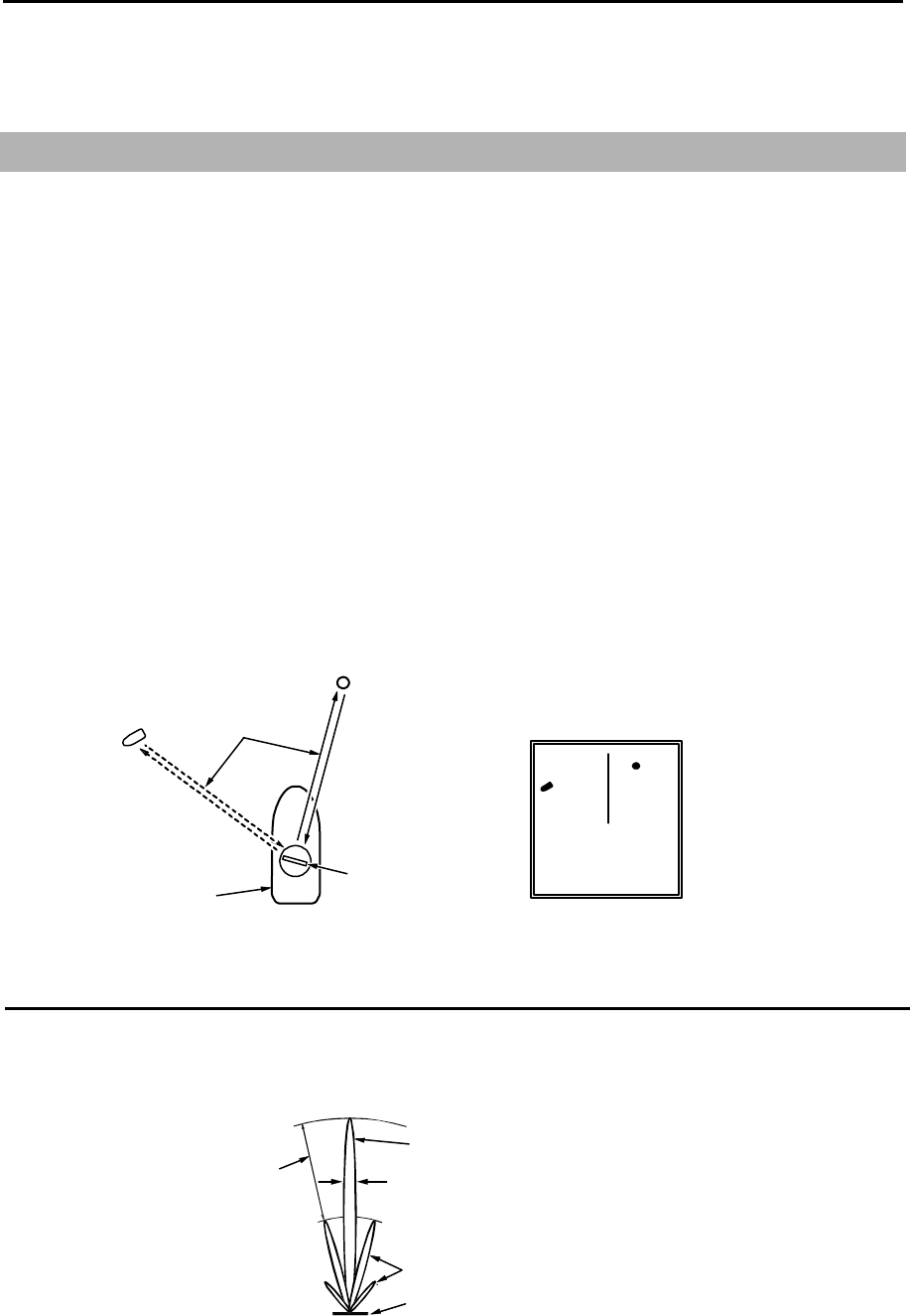
MDC-7000P/7900P Series Chapter 8 Principal of radar system
0093169006-05E 8-1
Chapter 8 Principal of radar system
8.1 What is radar system?
The radar is a navigation device that transmits a very high frequency radio wave referred to as
microwave from the antenna. The radar then receives the radio wave reflected by target(s) (e.g. other
ship, buoy, island, etc.) via the same antenna and converts the received radio wave to electronic
signals and sends these signals to the Display unit. The radar makes it possible to find objects (targets),
such as other ships, rocks or coastline, not seen by eyesight at night or in fog and allows ships to avoid
these potential hazards. As the antenna transmits during 360-degree rotation, it is possible to see the
current surrounding situation around your ship at a glance.
The microwave radiated from the radar is referred to as pulse wave and the transmitting and receiving
of these waves is alternated. Up to thousands of pulse waves are transmitted and received during one
rotation
The typical radar antenna is of parabolic type or slotted array type and its performance is essential for
good radar performance. Some of factors affecting the quality of the target returns are antenna beam
width and side lobe level. The narrow beam width provides high resolution for angular orientation to
distinguish objects and the low side lobe level reduces false image effect.
Radar wave
Antenna
(during rotating)
Own
ship
Othe
r
ship
Buo
y
Radar display
Side lobe
The main lobe means the strongest radiated beam sent from the specific antenna, and the other
weaker beams, are referred to as a side lobes. A side lobe level is a difference between the largest side
lobe level and main lobe level.
Main lobe
Beam width
Side lobe level
Side lobe
Antenna pattern
Antenna
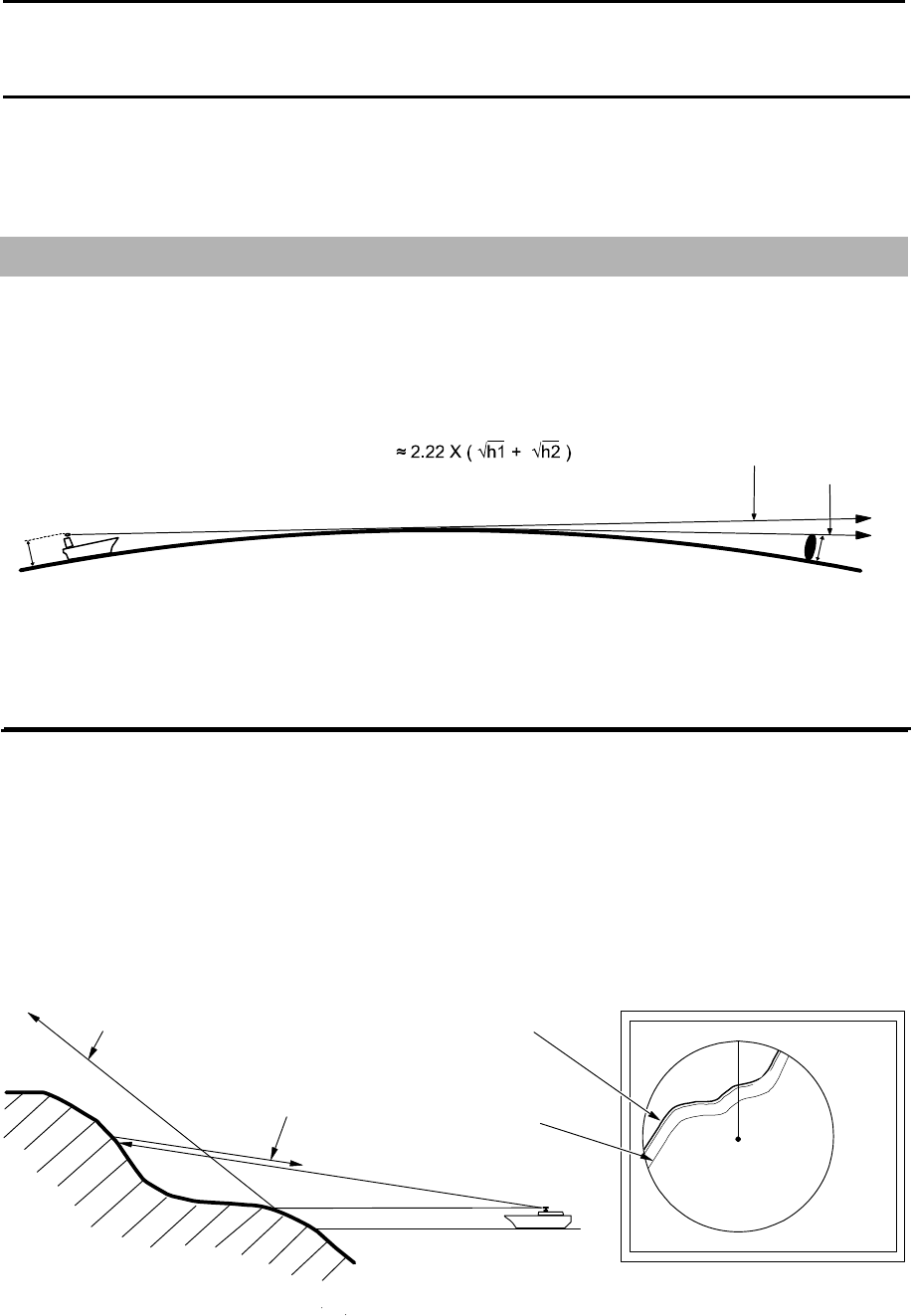
Chapter 8 Principal of radar system MDC-7000P/7900P Series
0093169006-05E 8-2
Beam width
Antenna beam width is defined as the angle where the radiation power density is within a half of
maximum power density (-3 dB) in main lobe (also, referred to as “half value width”).
8.2 Characteristics of radar radio wave
The radar radio wave propagates slightly along the ground (primarily line of sight). This characteristic
varies depending on density of atmosphere, but is generally calculated according to the formula as
shown below, considering that the distance with radar sight D is about 6 % longer than the distance with
optical sight.
h2
Radar radio wave
Sight line
Earth
h1
Characteristics of radar radio wave
D(NM)
h2 : Target height (m)
h1 : Antenna height (m)
Target hardness reflected
The strength of the reflected wave from a target varies depending on not only the distance from the
target, its height or size, but also its material and features. A target with a low degree of reflection or low
incident angle, such as FRP (Fiber Reinforced Plastic) and wooden ship is not reflected well. Therefore,
care shall be taken that a FRP ship, a wooden ship or an object such as sand, a sandbar and muddy
cay are poor radar targets.
Since the distance from the coastline, etc. to your ship on a radar image tends to be seen as longer
than that from the actual coastline, more caution should be paid when navigating around such objects.
Seen
Not seen 3
1
HU
Coastline on radar image
Actual (not seen)
coastline
Example of targets hard to be reflected
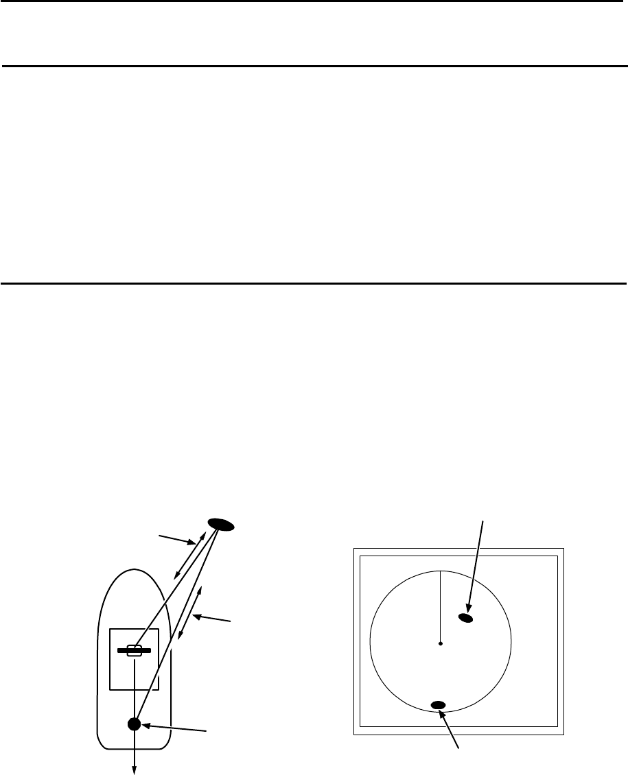
MDC-7000P/7900P Series Chapter 8 Principal of radar system
0093169006-05E 8-3
Radar shadow
Since radar radio wave is line of sight in nature your stack mast close to the antenna or, a large ship or
mountain may create blind spots for which the radar cannot penetrate. In such cases, they may
completely or partially hide targets and cast a long shadow.
Since the shadow of your stack or mast is known at the time of installation, proper selection of the
antenna location is necessary to reduce the shadow effect. Since targets in this shadow area is less
likely to be seen than in open sea, extra attention should be paid in shadowed areas.
False image
An image that does not actually exist (false image) at sea may appear on the display.
The phenomena that causes false echoes are categorized and be described as follows:
● Virtual image
The image of a large physical object in proximity may appear in two different orientations. One is a real
image and the other is a false image caused by wave re-reflected by the stack or the mast, etc. On the
display, one image appears at the correct distance and bearing, and another one appears in the
direction of a stack, a mast, etc. These images may also be generated by re-reflection from bridges and
quays too.
Passage of direct
reflection
Passage of
secondary
reflection
Direction of false image
Real image
False image
False image caused by virtual image
Mast, etc
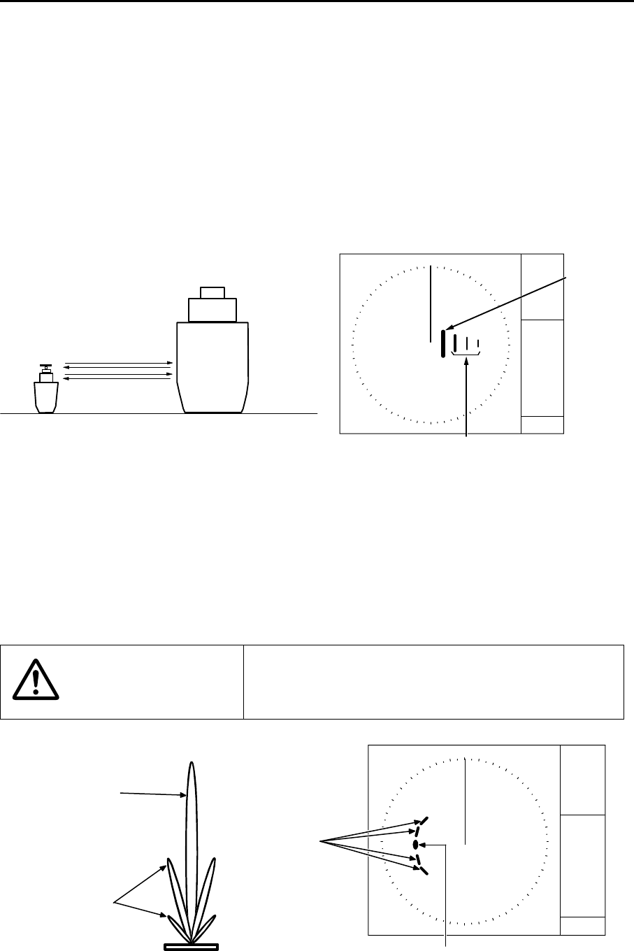
Chapter 8 Principal of radar system MDC-7000P/7900P Series
0093169006-05E 8-4
● Duplicate target images
When there is a big reflective surface nearby and it is perpendicular at a close distance (i.e. when your
ship is passed by a big ship, etc.), the radio wave bounces between own ship and the other ship.
Therefore, two to four images may appear at equal range in the direction of this target. The false
images generated by this multi-path reflection are referred to as “double targets”. In this case, the
closest target is the real image.
If the distance and bearing between own ship and the reflective target changes, then the duplicate
targets will disappear. Therefore, this false image can be easily distinguished.
Double image
Real image
False image caused by double image
Own ship Large vessel
●Side lobe images
The microwave beam radiated from the antenna has a side lobe in different direction than that of the
main beam. Since this side lobe level is lower than that of main beam, the effect is negligible for targets
at long range, but a close, strong reflecting target may cause false image appearing in a circular arc
shape.
CAUTION
When own ship is close to large targets such as land, a
circular image may appear.
Side lobe
Main lobe
Antenna
False image
by sidelobe
Real image
False image caused by sidelobe

MDC-7000P/7900P Series Chapter 8 Principal of radar system
0093169006-05E 8-5
●Skip target images
False image of a distant target caused by “skip” phenomenon
Depending on weather conditions, skip caused by the temperature inversion layer of air, etc. may
appear. In this case, the radio wave may unusually propagate to distant targets out of the radar range. A
target at more than the maximum range may appear as an image, and may be displayed as a false
image with closer distance than the actual one. This phenomenon is a result of the wide range echo
delay time exceeding the transmission period, and is displayed as echo in the following rotation. If the
range scale is changed and the target range is changed, it can be judged as a false image.
8.3 Radar interference
When the radar with the same frequency band is used nearby, interference noise appears on a display.
Although appearance of interference is not constant, the shape is almost always swirling or radial.
This series of radars features an IR (interference rejection) facility to reduce this interference.
- This page intentionally left blank.-

MDC-7000P/7900P Series Chapter 9 Simple fault diagnosis
0093169006-05E 9-1
Chapter 9 Simple fault diagnosis
For simple fault diagnosis, follow below procedures.
For faults not listed below, refer to Installation manual.
Items posted
9.1 No alarm sound. (ALARM TEST)
9.2 Operation unit (panel) key is not operational. (PANEL TEST)
9.3 TT (ARPA) is not operational. (DIAGNOSE TT)
9.4 No AIS display. (DIAGNOSE AIS)
9.5 Need to confirm serial input. (SERIAL MONITOR)
9.6 No radar video display. (ANT MONITOR)
9.7 Frozen display.
9.8 About alarms
1 Press MENU key to display “Menu”.
Select [SYSTEM] => [PROTECT MENU] => [ON]
2 Enter [PASSWORD], and press ENT key to display [MAINTENANCE] menu.
3 Press MENU key to display “Menu”.
Select [MAINTENANCE] => [BITE] =>
>MAINTENANCE
>BITE
ALARM TEST
PANEL TEST
DIAGNOSE TT
DIAGNOSE AIS
SERIAL MONITOR
ANT MONITOR
SD CARD
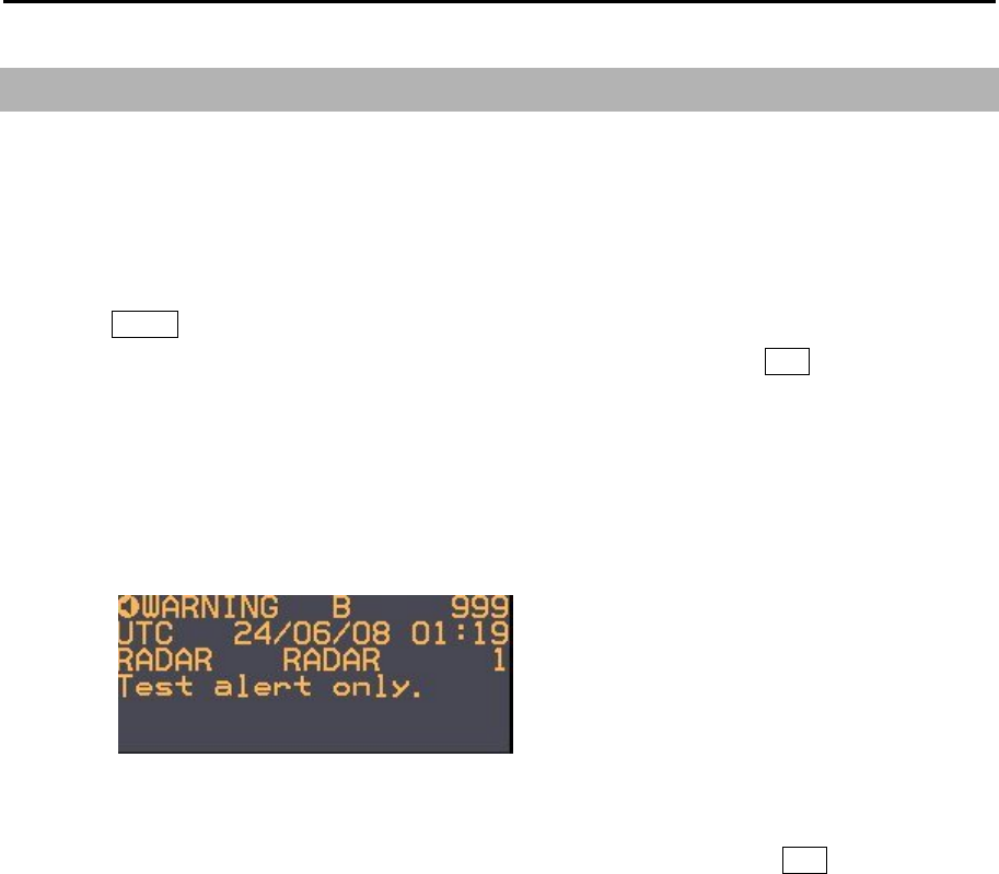
Chapter 9 Simple fault diagnosis MDC-7000P/7900P Series
0093169006-05E 9-2
9.1 No alarm sound
Follow this procedure to troubleshoot no alarm sound trouble.
First, select [SYSTEM] => [SOUND] and confirm that the status is [ON].
Note: This menu is protected in normal. To cancel the protection, refer to 1.3 Menu usage “Display
[MAINTENANCE] menu”.
1 Press MENU key to display “Menu”.
Select [MAINTENANCE] => [BITE] => [ALARM TEST] => [ON], and press ENT key after selection.
2 Please confirm the frequency setting, because it may be hard to hear the alarm sound according to
the setting value.
Select [SYSTEM] => [SOUND] => [FREQUENCY] (Initial setting: 4)
3 Alarm sounds (two times) and alarm display appears at the lower right of the display.
Alarms displayed are [WARNING B 999], [Test alert only.].
4 Confirmation is completed if alarm sounded.
5 Alarm sounds are repeated every 60 seconds.
Select [MAINTENANCE] => [BITE] => [ALARM TEST] => [OFF], and press ENT key to turn alarm
test off.
Note: After running the test and there is still no alarm sound the Operation unit has malfunction.
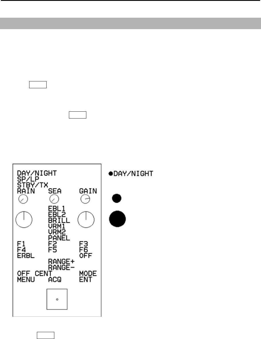
MDC-7000P/7900P Series Chapter 9 Simple fault diagnosis
0093169006-05E 9-3
9.2 Operation unit (panel) key is not operational
Following procedure is a test for Operation unit in case some keys don’t function properly. First please
make sure all cables are connected properly.
Note: This menu is protected in normal. To cancel the protection, refer to 1.3 Menu usage “Display
[MAINTENANCE] menu”.
1 Press MENU key to display “Menu”.
Select [MAINTENANCE] => [BITE] => [PANEL TEST] =>.
2 Panel illustration will appear on the display.
3 Press any key expect MENU key.
[●] mark will appear at the left side of key name during the key press.
The line in the circle will rotate when the knob is turned.
The circle color will change when the knob is pressed.
The small circle in the square will move when trackball is moved.
4 Pressing MENU key will complete the test.
Operation unit (panel) malfunctions, if No.3 item is not normally displayed.
Chapter 9 Simple fault diagnosis MDC-7000P/7900P Series
0093169006-05E 9-4
9.3 TT is not operational
This procedure is applied when acquisition operation does not start despite ACQ key being pressed.
First, confirm that [INPUT RNG] is properly set.
The targets outside of [INPUT RNG] will not be acquired.
This procedure confirms ATA function.
Note: This menu is protected in normal. To cancel the protection, refer to 1.3 Menu usage “Display
[MAINTENANCE] menu”.
1 Press MENU key to display “Menu”.
Select [MAINTENANCE] => [BITE] => [DIAGNOSE TT] =>.
2 Confirm [ ] mark appears on the left side of [HDG].
3 Turn trackball to the left to complete.
If [x] mark is displayed in step 2, then confirm HDG input for Display unit.

MDC-7000P/7900P Series Chapter 9 Simple fault diagnosis
0093169006-05E 9-5
9.4 No AIS display
This procedure is applied when AIS is not displayed.
First, confirm that [INPUT RNG] is properly set.
Targets outside of [INPUT RNG] are not displayed.
Confirm AIS function by following steps.
Note: This menu is protected in normal. To cancel the protection, refer to 1.3 Menu usage “Display
[MAINTENANCE] menu”.
1 Press MENU key to display “Menu”.
Select [MAINTENANCE] => [BITE] => [DIAGNOSE AIS] =>.
2 Confirm that the [ ] mark appears at the left side of [AIS DATA], [HDG], [SPD], [LAT/LON] and
[COG/SOG].
3 Turn trackball to the left to complete.
If [x] mark is displayed in step 2, then
In the case of [AIS DATA]: No valid AIS data input.
Confirm AIS receiver connected to Display unit.
AIS DATA is usually input to AIS (J2) connector.
In the case of [HDG]: No valid HDG input.
Confirm HDG input of Display unit.
HDG is usually input to GYRO connector.
In the case of [SPD]: No valid SPD input.
Confirm SPD input of Display unit.
SPD is usually input to SDME (J6) connector.
In the case of [LAT/LON]: No valid LAT/LON input.
Confirm LAT/LON input of Display unit.
LAT/LON is usually input to EPFS (J5) connector.
In the case of [COG/SOG]: No valid COG/SOG input.
Confirm COG/SOG input of Display unit.
COG/SOG is usually input to SDME (J6) or EPFS (J5) connector.
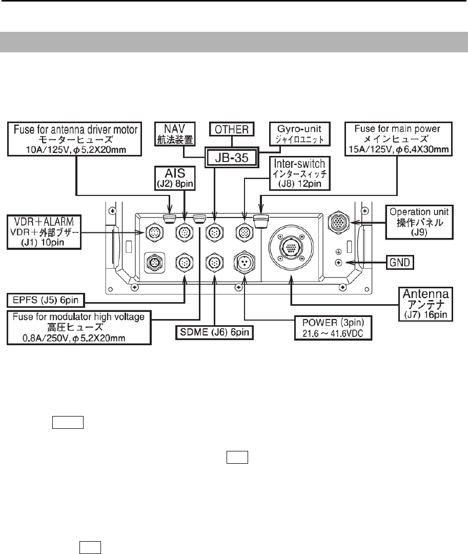
Chapter 9 Simple fault diagnosis MDC-7000P/7900P Series
0093169006-05E 9-6
9.5 Need to confirm serial input
This procedure is applied to confirm serial input of Display unit.
Serial input of connectors can be confirmed with the following 6 connectors:
AIS (J2), NAV, GYRO-unit, OTHER (JB-35), EPFS (J5), SDME (J6).
Note: This menu is protected in normal. To cancel the protection, refer to 1.3 Menu usage “Display
[MAINTENANCE] menu”.
1 Press MENU key to display “Menu”.
Select [MAINTENANCE] => [I/O] => [SERIAL MONITOR] => select [NAV], [EPFS], [SDME],
[GYRO], [OTHER], [AIS] or [ALL], and press ENT key.
[ALL] can confirm the data of all ports at a time.
2 Input data will be displayed.
Since the data keeps coming in and the display keeps changing it may be hard to observe the
sentences.
By pressing ENT key, data display will stop temporarily to confirm data content.
3 Turn trackball to left to complete.
Data confirming item in step 2
In the case that data is not displayed: Confirm input data device connected to Display unit.
In the case that data is displayed but is garbled: Confirm baud rate (FORMAT).

MDC-7000P/7900P Series Chapter 9 Simple fault diagnosis
0093169006-05E 9-7
9.6 No radar video display
This procedure is applied when no radar video (Echo) is displayed on the display.
Note: This menu is protected in normal. To cancel the protection, refer to 1.3 Menu usage “Display
[MAINTENANCE] menu”.
1 Press MENU key to display “Menu”.
Select [MAINTENANCE] => [BITE] => [ANT MONITOR] =>.
2 Antenna status will be displayed.
3 Turn trackball to left to complete.
Antenna status criteria in step 2
Connected scanner model name and type:
HIGH VOLTAGE: If the value is other than xxx to xxx, indicates high voltage malfunction.
MAG CURRENT MONI: If the value is other than xx to xxx, indicates magnetron malfunction.
MAG HEATER: If the value is other than xx to xxx, indicates magnetron malfunction.
MOTOR MONI:
TUNE VOLTAGE: If the value is other than xx to xxx, indicates magnetron or Front End Module failure.
RATE OF ROTATION: Antenna rotation (rpm).
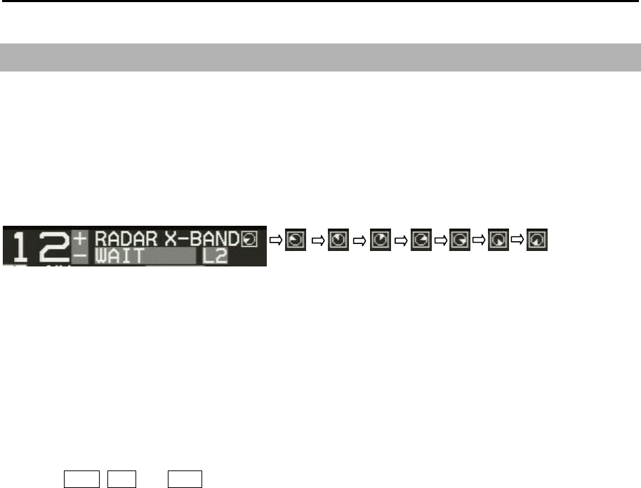
Chapter 9 Simple fault diagnosis MDC-7000P/7900P Series
0093169006-05E 9-8
9.7 Frozen Display
Following procedure applies for troubleshooting Frozen Display phenomenon.
Indication of presentation failure
You can aware of a display presentation failure from identification conspicuous periodically time
element on the display.
This element is located upper right of the display by eight pattern triangle icons.
These icons will change every two seconds, three angles of directions turn to the clockwise.
When this movement stopped, radar system will be stopping.
Restart Display unit immediately.
Frozen Display refers to case when video is not refreshed or cursor is not responsive.
1 Turn GAIN, SEA and RAIN knob to confirm changes of video (Echo).
2 Turn trackball to confirm if cursor is moving.
While Menu is displayed, confirm if menu selection can be changed.
When malfunction of either step 1 or step 2 is found, the display is frozen.
Restart Display unit immediately.
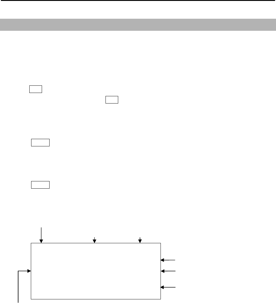
MDC-7000P/7900P Series Chapter 9 Simple fault diagnosis
0093169006-05E 9-9
●ALARM A 9999999
UTC 20/05/15 12:34
DGPS EPFS 999999
MESSAGE. . . . . . . . . . . . . . . .
. . . . . . . . . . . . . . . . . . . . . . . .
(ALARM and WARNING blinks until acknowledging alarm)
Date when warning and alarm
is generated.
Error message
Error device ID
Instance number
Alarm ID
Category
Icon and Priority:
ALARM / WARNING / CAUTION
9.8 About alarms
If any malfunction or operation error has been detected in the radar, or if the external device gives the
ALR sentence input, then alarms, warnings and cautions shown below appear at the lower right of the
display.
Abnormalities are categorized as [Alarm], [Warning] and [Caution]. When alarm display actually
appears and there is something wrong with radar, record the alarm details by type, location and status
and press OFF key. The alarm sound and display will disappear. Multiple errors may be displayed one
by one. Record all alarms and press OFF key for every alarm. The type of [Alarm], [Warning] and
[Caution] are shown below.
The two or more alarms occur at the same time, then it is possible to confirm all the alarms in [LIST].
1 Press MENU key to display “Menu”.
Select [ALARM] => [LIST] =>
Alarms occurred since Power ON can be confirmed by [HISTORY LIST].
1 Press MENU key to display “Menu”.
Select [ALARM] => [HISTORY LIST] =>
Refer to 1.1 Radar Display “Alarm display area”.

Chapter 9 Simple fault diagnosis MDC-7000P/7900P Series
0093169006-05E 9-10
Alarm list
List of system alarm and message.
Category
Priority (A: ALARM, W: Warning, C: Caution)
ID number (0-9999: IMO, 10000-9999999: Maker)
Instance number
ALR number
Contents Cause
A W 190 1 57 AIS targets exceed the
limit.
Number of AIS targets exceeding the
maximum 900 has been input.
A W 190 2 54 Tracked targets exceeded
the limit.
Number of tracked targets in TT (ARPA)
exceeded the maximum 100.
A W 190 3 56 AIS input targets
exceeded the limit.
Number of AIS targets exceeding the
maximum 900 has been input.
B C 190 4 58 AIS targets overload.
(95%)
Number of AIS targets being input
exceeded 855.
B C 190 5 55 Tracked targets overload.
(95%)
Number of tracking targets exceeded 95.
A A 191 1 3 Tracked target exceeded
the CPA/TCPA limit.
Tracked target has turned into dangerous
target.
A A 191 2 8 AIS target exceeded the
CPA/TCPA limit.
AIS target has turned into dangerous
target.
A W 192 1 4 Tracked target entered
into the guard zone.
Tracked target has entered into the guard
zone.
A W 192 2 5 Auto acquisition of a radar
target.
Captured a target entered into auto
acquisition area.
A W 192 3 9 AIS target entered into the
guard zone.
AIS target entered into the guard zone.
A W 192 4 10 Auto activation of an AIS
target.
A sleeping target has been activated.
A W 193 1 1 Tracked target is lost. TT (ARPA) has been lost.
A W 193 2 7 AIS target is lost. AIS target has been lost.
A W 193 3 2 Ref tracked target is lost. Ref tracked target has been lost.
B W 194 1 22 HDG is unavailable. THS or HDT are not inputted.
B W 194 2 23 SDP is unavailable. VBW, VTG, RMA or RMC are not inputted.
B W 194 3 24 COG/SOG is unavailable. COG/SOG is not inputted.
B W 194 4 25 SET/DRIFT data is
unavailable.
VDR is not inputted.

MDC-7000P/7900P Series Chapter 9 Simple fault diagnosis
0093169006-05E 9-11
B W 194 5 26 LAT/LON data is
unavailable.
GLL or GGA, GNS, RMC, RMA are not
inputted.
B W 194 6 27 DATUM data is
unavailable.
DTM is not input.
B W 194 7 28 TIME data is unavailable. ZDA or RMC, GGA are not input.
B C 194 8 60 AIS no OS COG/SOG
data.
Own ship’s data that is necessary for AIS
are not input.
B W 194 9 61 AIS no data. There is no AIS data.
VDM is not input from AIS.
B C 194 13 29 HDG is manual. There is not heading signal.
B C 194 14 30 SDP is manual. There is not speed signal.
B C 194 15 31 COG/SOG is manual. There are not ground course and speed
signal.
B C 194 16 32 SET/DRIFT is manual. There is not tide signal.
B C 194 17 33 LAT/LON is manual. There are not latitude and longitude signal.
B C 194 18 80 Receive alert of any signal
or sensor in use.
Receive alert of any signal or sensors in
use.
B C 194 25 109 AIS no data. There is no AIS data.
VDM is not input from AIS.
B C 194 26 110 SPD is unavailable. VBW, VTG, RMA or RMC are not inputted.
B C 194 27 111 COG/SOG is unavailable. COG/SOG is not inputted.
B W 999 1 89 Test alert only. Under alert test.
A W 10000 1 53 Echo area alarm detected. Images are detected in echo alarm area.
A W 10000 2 15 Echo map area alarm
detected.
Images were detected in map area.
B C 10000 3 11 Activated AIS target
without HDG or COG.
There is neither ship’s bearing nor fairway
of AIS active target input data to HDG or
COG.
B C 11000 1 14 Nav line exceeded. Own ship crossed the Nav line.
B C 11000 2 62 Received AIS message. Received AIS message to OWN ship.
B C 12000 1 16 Change to relative
bearing.
True bearing is not inputted.
B C 12000 2 17 Change to relative vector. VBW, VTG or VDR are not inputted.
B C 12000 3 18 Change to relative past
position.
VBW, VTG or VDR are not inputted.
B C 12000 4 19 Change to head up. THS, HDT, HDM or VTG, RMA, RMC are
not inputted.
B C 12000 5 20 Change EBL origin
position.
THS, HDT, HDM or VTG, RMA, RMC are
not inputted.

Chapter 9 Simple fault diagnosis MDC-7000P/7900P Series
0093169006-05E 9-12
B C 12000 6 34 Change to sea
stabilization.
Ship’s bearing: THS, HDT, HDM, VTG
Course against water: VBW
Speed: VBW, VTG, VHW are not input.
B C 12000 7 64 Change to reference
antenna.
The set CCRP went beyond radar display.
Reference has moved to antenna position.
A A 12000 8 65 Cannot use the CCRP. Cannot display CCRP position. Change
position or range.
B C 12000 9 21 Change to off process. THS, HDT, HDM or VTG, RMA, RMC are
not inputted.
B C 12000 10 35 Change to ground
stabilization
Speed: VBW or VHW is not input.
Change to ground stabilization. Check
VBW or VHW sentence.
B C 12000 11 36 Change SOG input to
EPFS
Change SOG input source from SDME
(VBW) to EPFS (VTG).
B C 16000 1 47 Inter-switch not
connected.
NAV ports between master and slave are
not connected.
B C 16000 2 59 AIS alarm signal. Alarm for abnormality is input in AIS alarm
terminal of AIS port or the terminals are
open.
B C 16000 3 66 No WGS84 DATUM. Input geodetic system is not WGS84.
A A 17000 1 41 Antenna not connected. Connector of Antenna may not be
connected to Antenna, or Scanner unit
may be faulty.
A A 17000 2 42 Antenna magnetron
current abnormal.
Magnetron may be at the end of life or
transmission high voltage fuse blown.
A A 17000 3 43 Antenna magnetron
heater abnormal.
Something is wrong with magnetron or
Scanner unit.
A A 17000 4 44 Antenna magnetron high
voltage abnormal.
High voltage fuse for transmission blown.
A A 17000 5 45 Antenna high voltage
abnormal.
High voltage fuse for transmission blown.
A A 17000 6 46 Motor voltage abnormal. Motor voltage fuse blown.
A A 17000 7 48 Azimuth abnormal. BP signal from Scanner unit is not
received.
May be fault in angle detecting sensor in
Scanner unit or poor connection at
connector.
A A 17000 8 49 Head line signal abnormal. SHF signal from Scanner unit is not
received.
May be fault in SHF sensor in Scanner unit
or rotation of antenna may be stopped.

MDC-7000P/7900P Series Chapter 9 Simple fault diagnosis
0093169006-05E 9-13
A A 17000 9 50 Trigger abnormal. Trigger from Scanner unit is not received.
A A 17000 10 51 Radar video abnormal. IF video from Scanner unit is not received.
A A 18000 1 13 Panel not connected. No communication between operating
panel is available. Connector (J9) is
disconnected.
B W 18001 1 37 Flash memory erase &
write error.
Flash memory erase and write error.
B W 18001 2 38 Flash memory erase error. Flash memory erase error.
B W 18001 3 39 Flash memory write error. Flash memory write error.
B W 18001 4 40 Flash memory checksum
error.
Flash memory checksum error.
B C 18002 1 71 SD card problem. SD card may be broken.
B C 18002 2 72 SD card not ready. There is not SD card.
B C 18002 3 73 SD card write protected. SD card is protect mode.
B C 18002 4 74 SD card not enough free
space.
Memory of SD card is not left.
B C 18002 5 75 Illegal data. The data does not agree.
B C 18002 6 76 USB memory problem. USB memory problem.
B C 18002 7 77 USB memory not ready. USB memory not ready.
B C 18002 8 78 USB memory write
protected
USB memory write protected
B C 18002 9 79 USB memory not enough
free space.
USB memory not enough free space.
B A 18003 1 JB-35 not connected. No communication between junction box
JB-35 is available. Connector J3 is
disconnected.
B A 18003 2 JB-35 not extended mode. There is not JB-35 with the extended
mode.

Chapter 9 Simple fault diagnosis MDC-7000P/7900P Series
0093169006-05E 9-14
OPERATION NOTE
MESSAGE
Operation note
Operation note display may appear at the lower right of the radar display as shown in below when an
operation error has been detected in the device.
When operation note display actually appears and there is something wrong with radar operation.
Type of Operation note
Contents Cause
Tracked target full. Acquired tracked target beyond the maximum
tracking number.
Tracked target no data. Deleted tracked target as there were no tracked
targets.
Tracked target out of range. Acquired tracked target beyond operating
distance set for targets.
Pre heating. Operated transmission key during pre-heating
countdown.
No HDG, LAT/LON signal. As signals of ship’s bearing, latitude/longitude
had not been input, functions that need those
signals have been disabled.
No HDG signal. As signals of ship’s bearing had not been input,
functions that need ship’s bearing signal were
disabled.
No SPD signal. As speed signal had not been input, functions
that needs speed signal were disabled.
Map data full. More than the specified number of COAST
LINE, NAV LINE, ROUTE, EVENT MKR and
AREA tried to attempt to register in map
function.
Cursor off. Cursor is not displayed.
Inter-switch changed the mode. During inter-switch connection, one Display unit
switched over inter-switch mode.
3 short audible signals, and after 5sec. this
message will disappear.

MDC-7000P/7900P Series Chapter 9 Simple fault diagnosis
0093169006-05E 9-15
No off center. In the maximum range, off center function was
disabled.
Tracking malfunction. BRG T As the result of TT test, the accuracy of bearing
has exceeded the reference.
Tracking malfunction. RNG As the result of TT test, the accuracy of range
has exceeded the reference.
Tracking malfunction. CPA As the result of TT test, the accuracy of CPA
has exceeded the reference.
Tracking malfunction. TCPA As the result of TT test, the accuracy of TCPA
has exceeded the reference.
Tracking malfunction. T CRS As the result of TT test, the accuracy of true
course has exceeded the reference.
Tracking malfunction. T SPD AS the result of TT test, the accuracy of true
speed has exceeded the reference.
Mode hold. Attempted to change mode during operation of
performance monitor. The mode is fixed at
H-UP.
Range hold. During starting up of performance monitor,
attempted to change the range. The range is
fixed at 24 NM.
Time to trial manoeuvre is less than 30 seconds. The remaining time of trial manoeuvre is less
than 30 seconds.
Reference target overload. Attempted to acquire reference target beyond 3.
Do not use MAN COG/SOG. Cannot use AIS with COG/SOG data inputted
by manual.
Do not use REF COG/SOG. Cannot use AIS with COG/SOG data calculated
by reference target.
Do not use CURRENT COG/SOG. Cannot use AIS with SET/DRIFT data inputted
by manual.
Do not use MAN STW. Cannot use AIS with speed data inputted by
manual.
Do not use MAN POSITION. Cannot use AIS with own ship position data
inputted by manual.
Time error. Cannot use AIS with no time data.
Do not use MAN OFFSET POSITION. Cannot use AIS with offset positon inputted by
manual.
- This page intentionally left blank.-
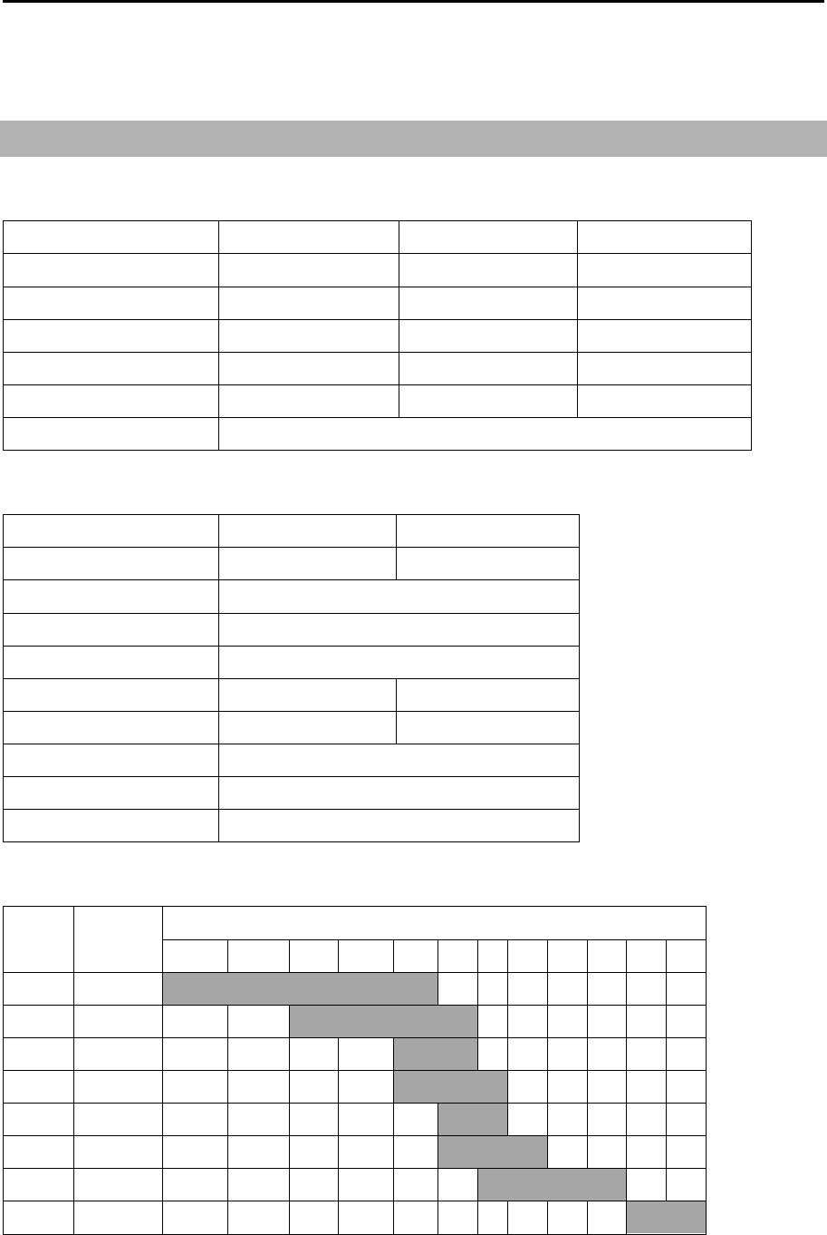
MDC-7000P/7900P Series Chapter 10 Specifications
0093169006-05E 10-1
Chapter 10 Specifications
10.1 Antenna and Scanner unit (Exposed)
Antenna
Model name RW701A-04 RW701A-06 RW701B-09
Antenna length 4feet 6feet 9feet
Horizontal beam width 1.8° 1.2° 0.8°
Vertical beam width 22° 22° 25°
Side lobe within ±10° -25dB -25dB -25dB
Side lobe outside ±10° -30dB -30dB -30dB
Polarization Horizontal
Scanner
Model name MDC-7012P/7912P MDC-7025P/7925P
Scanner unit RB808P RB809P
Type Up-mast
Rotation 24 rpm
Output frequency X-band: 9410MHz ± 30MHz
Output power (Peak) 12 kW 25 kW
Magnetron MAF1565N M1568BS
Performance Monitor KPM-20
Temperature -25°C to +55°C
Water protection IPX6
Range, PRF, Pulse width
PRF
(Hz)
Pulse
width
Range (NM)
0.125 0.25 0.5 0.75 1.5 3 6 12 24 48 64 96
2600 0.08us S1
2600 0.15us S2
2400 0.3us M1
2000 0.4us M2
1400 0.6us M3
1000 0.8us L1
600 1.2us L2
450 1.2us L3

Chapter 10 Specifications MDC-7000P/7900P Series
0093169006-05E 10-2
10.2 Display, Processor and Operation unit (Protected)
Model name MDC-7912P/7925P MDC-7012P/7025P
Display unit MRD-108P ---
Processor unit --- MRM-108P
Operation unit MRO-108P
Display size and type 19 inch color TFT LCD ---
Display Resolution 1280 X 1024 pixels (SXGA)
Effective diameter 282 mm (CAT2, CAT3) --- (CAT1 - CAT3)
Viewing distance 1 m Refer to specification of display.
Frequency band X-band 9410MHz ±30MHz (9380MHz to 9440MHz)
Speed class Normal speed class (< 30 knot)
Echo color Green/Yellow
Off-centering Max. 75%
Range data accuracy 8 m or 1 % of range scale selected, whichever is greater
Range 0.125, 0.25, 0.5, 0.75, 1.5, 3, 6, 12, 24, 48, 64, 96 NM
Up to 64 NM for transmit output 12 kW,
Up to 96 NM for transmit output 25 kW
Bearing accuracy ±1°
Presentation modes Head up, North up, and Course up
Functions CFAR (Clutter rejection), Interference rejection, Expansion,
Process (Residual image, Averaging), VRM, EBL, Parallel index, ERBL,
Cursor position (Lat/Lon), Bearing (true/relative), Trail (true/relative), Own
ship past track, MAP (Event mark, etc.), Analog RGB output, VDR output,
Inter-switch, Trial manoeuvre, C-map chart
NMEA Input/output 5 CH (with JB-35)
Power supply 21.6 VDC to 41.6 VDC
Power consumption
(at 24 VDC)
MDC-7012P/MDC-7912P: 150W or less
MDC-7025P/MDC-7925P: 200W or less
AIS
900 targets
TT (ARPA) 100 targets
Temperature -15°C to +55°C
Water protection Front panel (MDC-7912P/MDC-7925P) and Operation unit: IP23
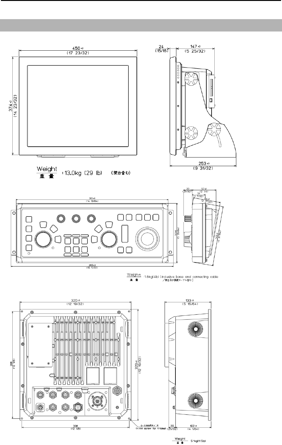
MDC-7000P/7900P Series Chapter 10 Specifications
0093169006-05E 10-3
10.3 External view and dimensions
Unit: mm (inch)
MRM-108P
MRD-108P
MRO-108P
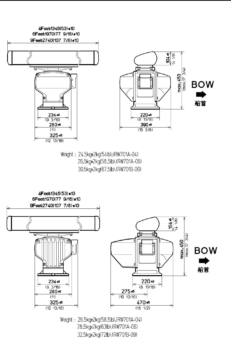
Chapter 10 Specifications MDC-7000P/7900P Series
0093169006-05E 10-4
RB808P
RB809P
Unit: mm (inch)
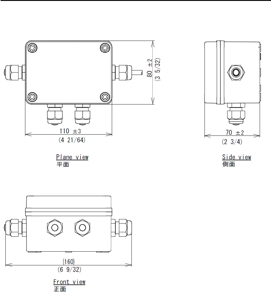
MDC-7000P/7900P Series Chapter 10 Specifications
0093169006-05E 10-5
Junction box (JB-35)
Unit: mm (inch)
- This page intentionally left blank.-
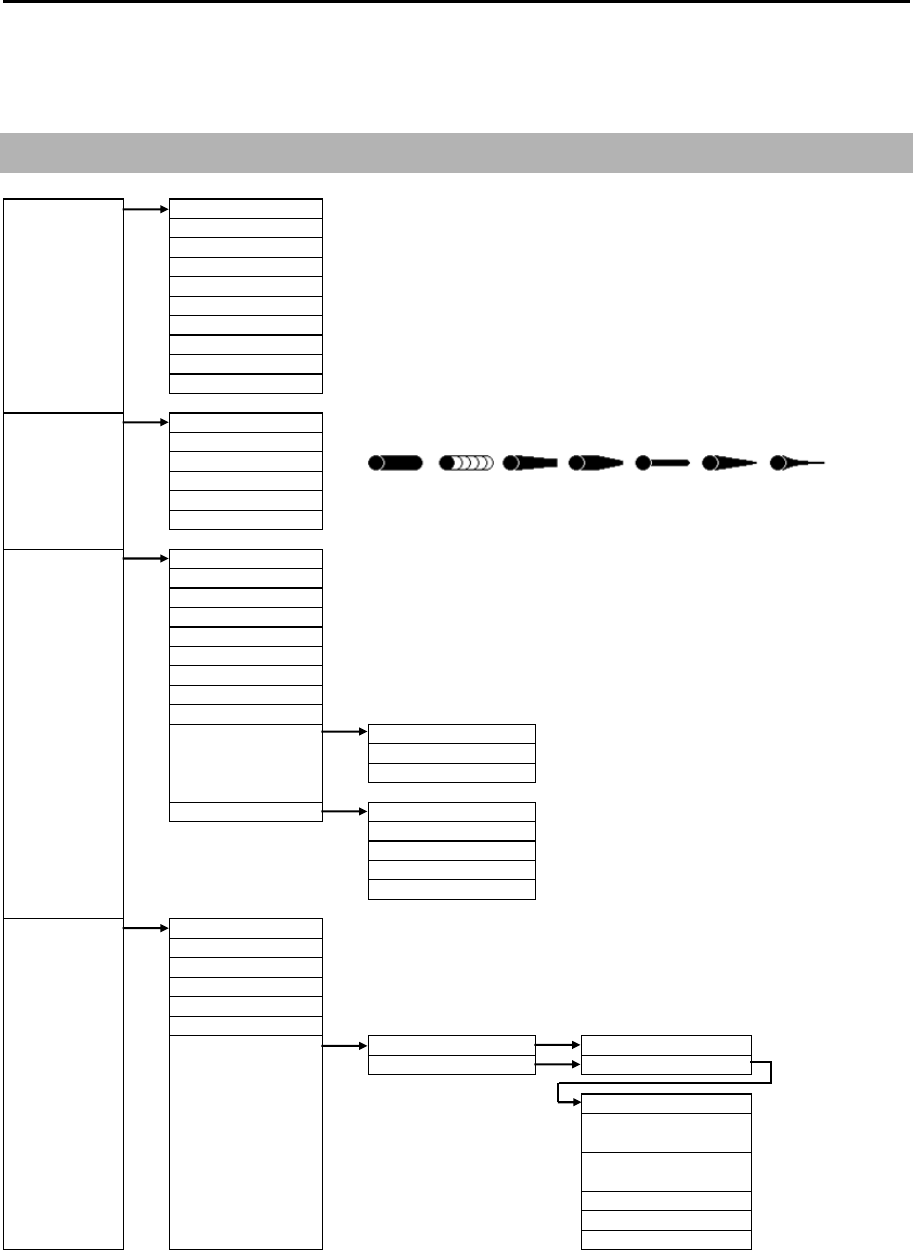
MDC-7000P/7900P Series Chapter 11 Appendix
0093169006-05E 11-1
Chapter 11 Appendix
11.1 Menu tree
ECHO PICTURE MODE ⇒
PROCESS ⇒
EXPANSION ⇒OFF, 1, 2, 3, 4
IR ⇒OFF, 1, 2, 3
VIDEO CONTRAST ⇒1, 2, 3, 4, 5
NOISE REJ ⇒OFF, 1, 2
COLOR REJ ⇒OFF, 1, 2, 3, 4, 5, 6, 7, 8, 9, 10, 11, 12, 13, 14
PULSE WIDTH ⇒S1, S2, M1, M2, M3, L1, L2, L3
SART ⇒OFF, ON
PICTURE RESET ⇒CANCEL, GO
TRAIL TRUE/REL ⇒REL, TRUE
TIME ⇒OFF, 30sec, 1min, 3min, 6min, 12min, 30min, 60min, PERM
SHAPE ⇒
TRAIL LEVEL ⇒1, 2, 3, 4, 5, 6, 7, 8, 9, 10, 11, 12, 13, 14, 15
CLEAR ⇒CANCEL, GO
RANGE KEEP ⇒OFF, ON
DISPLAY DISPLAY CENTER ⇒ANT, CCRP
ANT POSN ⇒OFF, ON
OFF CENT POINT ⇒CURSOR, OPPOSITE
STAB MODE ⇒SEA, GND
TM RESET
C UP RESET
RANGE UNIT ⇒NM, km
ROTATION MARGIN ⇒0.0° to 30.0°
ROTATION SPEED ⇒FAST, MEDIUM, SLOW
FERRY MODE FERRY MODE ⇒OFF, ON
(ON or OFF of this menu links
HDG ⇒0°, 180°
FERRY MENU of STARTUP MENU)
HEADING LINE ⇒UP, DOWN
BIRDVIEW VIEW AREA DISP ⇒OFF, ON
VIEW HEIGHT ⇒50 to 500
VIEW POINT ⇒50 to 500
FRAME POINT ⇒20 to 200
FRAME LEFT/RIGHT ⇒-200 to 200
ALARM ECHO ALARM ⇒OFF, IN, OUT
BRG REL ⇒000.0 to 359.9°
WIDTH ⇒000.0 to 360.0°
RNG ⇒000.0 to 999.9NM
DEPTH ⇒000.0 to 999.9NM
MAP AREA ALARM ⇒OFF, IN, OUT
EDIT CURSOR 1 to 10 ⇒CANCEL, GO
BLOCK NUMBER 1 to 10
NUMBER
LAT ⇒90°00.000S
to 90°00.000N
LON ⇒180°00.000W
to 180°00.000E
COLOR ⇒8 colors
DIVIDE ⇒OFF, ON
SET
PICTURE1, PICTURE 2, PICTURE3, NEAR, FAR, HARBOR, ROUGH SEA, RAIN, PURE
OFF, CORRELATION1, CORRELATION2
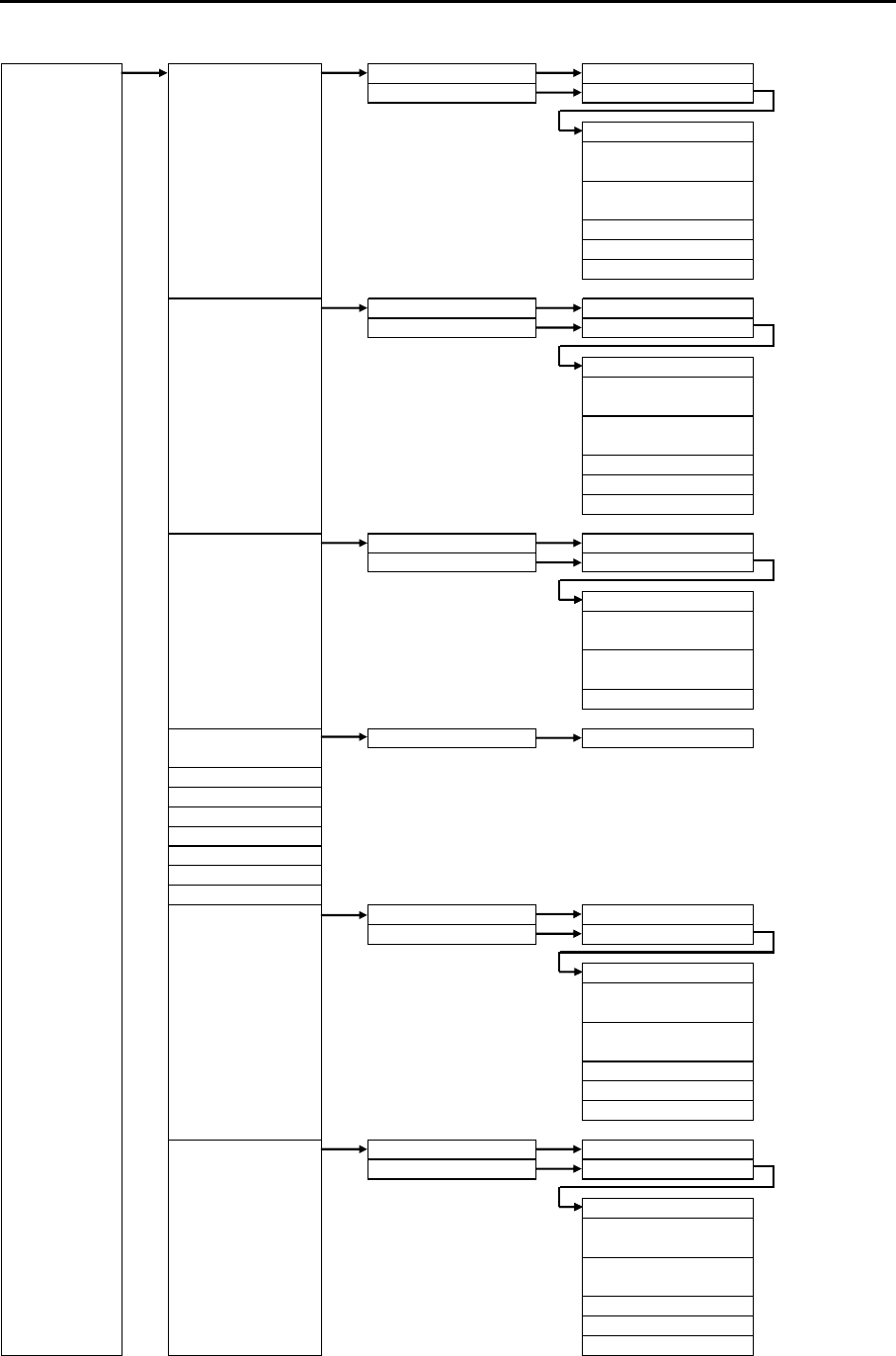
Chapter 11 Appendix MDC-7000P/7900P Series
0093169006-05E 11-2
ALARM MOVE CURSOR 1 to 10 ⇒CANCEL, GO
BLOCK NUMBER 1 to 10
NUMBER ⇒1 to 100
LAT ⇒90°00.000S
to 90°00.000N
LON ⇒180°00.000W
to 180°00.000E
COLOR ⇒8 colors
DIVIDE ⇒OFF, ON
SET
ADD CURSOR 1 to 10 ⇒CANCEL, GO
BLOCK NUMBER 1 to 10
NUMBER ⇒1 to 100
LAT ⇒90°00.000S
to 90°00.000N
LON ⇒180°00.000W
to 180°00.000E
COLOR ⇒8 colors
DIVIDE ⇒OFF, ON
SET
DELETE CURSOR 1 to 10 ⇒CANCEL, GO
BLOCK NUMBER 1 to 10
NUMBER ⇒1 to 100
LAT ⇒90°00.000S
to 90°00.000N
LON ⇒180°00.000W
to 180°00.000E
SET
CLEAR BLOCK NUMBER 1 to 10 ⇒CANCEL, GO
DETECT LEVEL ⇒1, 2, 3, 4, 5, 6, 7, 8, 9, 10, 11, 12, 13, 14, 15
GUARD ZONE ⇒OFF, ON
BRG REL ⇒000.0 to 359.9°
WIDTH ⇒000.0 to 360.0°
RNG ⇒000.0 to 999.9NM
DEPTH ⇒000.0 to 999.9NM
NAV LINE CROSS ⇒OFF, ON
EDIT CURSOR 1 to 10 ⇒CANCEL, GO
BLOCK NUMBER 1 to 10
NUMBER
LAT ⇒90°00.000S
to 90°00.000N
LON ⇒180°00.000W
to 180°00.000E
COLOR ⇒8 colors
DIVIDE ⇒OFF, ON
SET
MOVE CURSOR 1 to 10 ⇒CANCEL, GO
BLOCK NUMBER 1 to 10
NUMBER ⇒1 to 100
LAT ⇒90°00.000S
to 90°00.000N
LON ⇒180°00.000W
to 180°00.000E
COLOR ⇒8 colors
DIVIDE ⇒OFF, ON
SET

MDC-7000P/7900P Series Chapter 11 Appendix
0093169006-05E 11-3
ALARM ADD CURSOR 1 to 10 ⇒CANCEL, GO
BLOCK NUMBER 1 to 10
NUMBER ⇒1 to 100
LAT ⇒90°00.000S
to 90°00.000N
LON ⇒180°00.000W
to 180°00.000E
COLOR ⇒8 colors
DIVIDE ⇒OFF, ON
SET
DELETE CURSOR 1 to 10 ⇒CANCEL, GO
BLOCK NUMBER 1 to 10
NUMBER ⇒1 to 100
LAT ⇒90°00.000S
to 90°00.000N
LON ⇒180°00.000W
to 180°00.000E
SET
CLEAR BLOCK NUMBER 1 to 10 ⇒CANCEL, GO
LIST
HISTORY LIST
HISTORY LIST SORT PRIORITY ⇒ALL, ALARMS, WARNINGS, CAUTIONS
CATEGORY ⇒ALL, A, B
TIME ⇒LAST IN, FIRST IN
ALARM ON/OFF TT AUTO ACQ ⇒OFF, ON
AIS AUTO ACQ ⇒OFF, ON
MESSAGE ⇒OFF, ON
TARGET VECT TRUE/REL ⇒TRUE , REL
TIME ⇒
OFF, 30sec, 1min, 3min, 6min, 12min, 30min, 60min
TIME INCREMENT ⇒OFF, 2, 3, 5, 10
STAB INDICATOR ⇒OFF, ON
PATH PREDICTOR ⇒OFF, ON
CPA/TCPA ⇒OFF, ON
AIS ID DISP TYPE NUMBER ⇒OFF, ON
NAME ⇒OFF, ON
MMSI ⇒OFF, ON
IMO ⇒OFF, ON
CALLSIGN ⇒OFF, ON
TT ID DISP TYPE NUMBER ⇒OFF, ON
LABEL ⇒OFF,ON
ID DISP SIZE ⇒X-SMALL, SMALL, MEDIUM, LARGE
INPUT RNG ⇒1.0 to 64.0NM
ASSOCIATION ASSOCIATION ⇒OFF, TT, AIS
CHG SELECTED TGT
SETTING RNG ⇒0.001 to 1.000 NM
CRS ⇒10.0 to 60.0°
SPD ⇒1.0 to 20.0 kn
SPD LIM ⇒1.0 to 10.0 kn
TIME REPRIEVE ⇒1 to 99sec
AUTO ACQ AREA ⇒OFF, ON
BRG REL ⇒000.0 to 359.9°
WIDTH ⇒000.0 to 360.0°
RNG ⇒000.0 to 999.9NM
DEPTH ⇒000.0 to 999.9NM
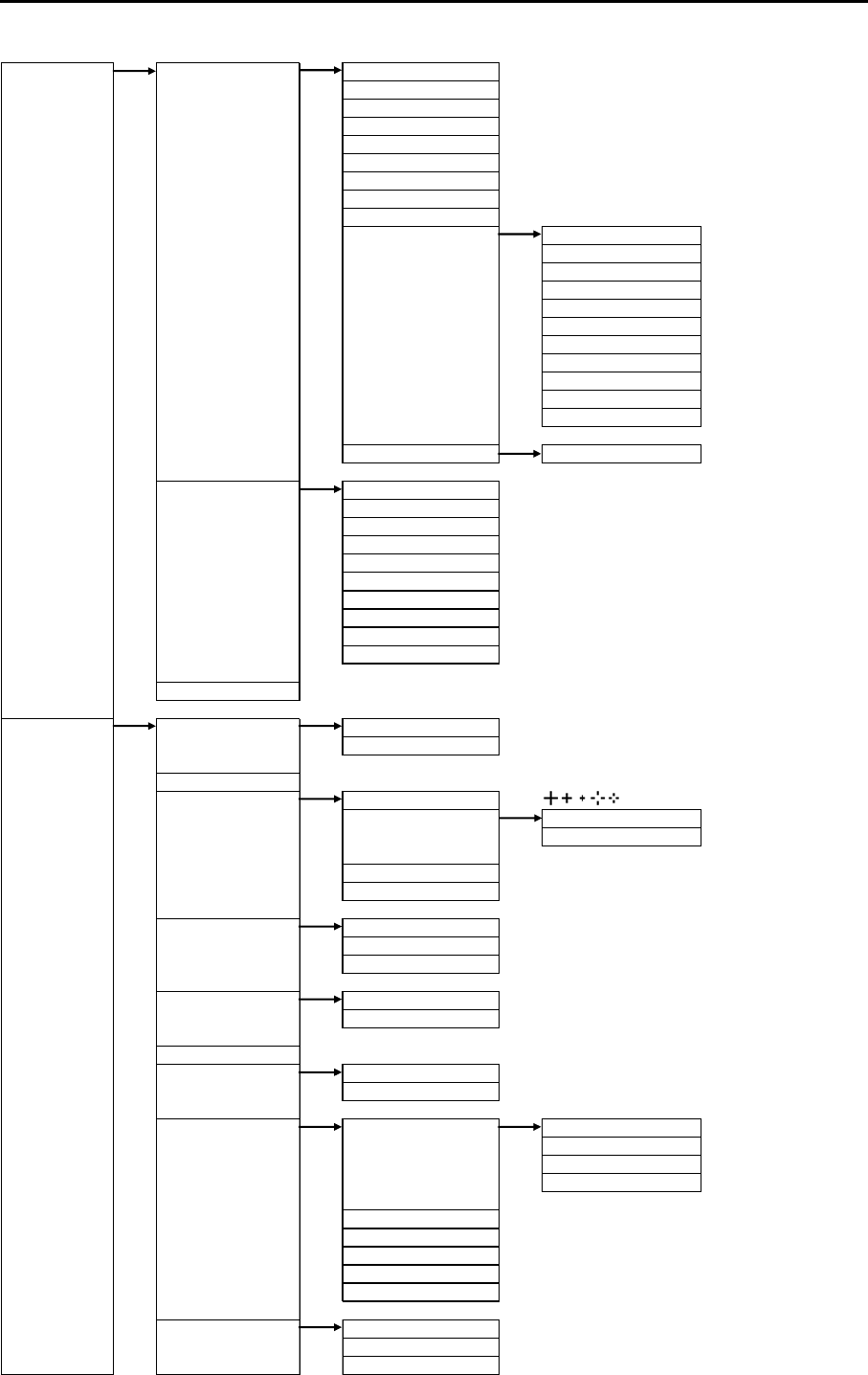
Chapter 11 Appendix MDC-7000P/7900P Series
0093169006-05E 11-4
TARGET AIS AIS ⇒OFF, ON
SELECT ID ⇒101 to 1000
ACTIVE/SLEEP
SHIP OUTLINE ⇒OFF, ON
HDG LINE ⇒OFF, ON
TURN INDICATOR ⇒OFF, ON
OS DISP ⇒OFF, ON
OS MMSI ⇒0 to 1073741824
MESSAGE DISP ⇒OFF, SLOW, MEDIUM, FAST
AIS FILTER CLASS A ⇒OFF, ON
CLASS B ⇒OFF, ON
RNG ⇒0.0 to 64.0NM
SPD ⇒0.0 to 100.0kn
CPA/TCPA ⇒OFF, ON
MOORED ⇒OFF, ON
AT ANCHOR ⇒OFF, ON
AGROUND ⇒OFF, ON
NUC ⇒OFF, ON
GUARD ZONE ⇒OFF, ON
ECHO ALARM ⇒OFF, ON
AIS ALARM SLEEPING LOST ⇒OFF, ON
TT TT ⇒OFF, ON
SELECT ID ⇒1 to 100
DELETE
EDIT LABEL ⇒10 words
ACQ
ALL DELETE
REF ACQ
TEST TGT ⇒OFF, ON
TGT LEVEL ⇒1, 2, 3, 4, 5, 6, 7, 8, 9, 10, 11, 12, 13, 14, 15
PERFORMANCE ⇒0 to 7
TRIAL MANOEUVRE ⇒CANCEL, GO
NAV TOOL RR RR ⇒OFF, ON
RR NUMBER ⇒DEFAULT, 5
BRG TRUE/REL ⇒TRUE, REL
CURSOR CURSOR SHAPE ⇒
CURSOR CURSOR ⇒OFF, ON
LAT/LON ⇒OFF, ON
CURSOR HUP MOVE ⇒OFF, ON
INFO ⇒OFF, ON
EBL EBL1 OFFSET ⇒RM, TM
EBL2 OFFSET ⇒RM, TM
EBL TRUE MOVE ⇒OFF, ON
VRM VRM1 UNIT ⇒NM, km, RNG LINK
VRM2 UNIT ⇒NM, km, RNG LINK
VRM/EBL CROSS ⇒OFF, ON
ERBL RNG ⇒LINE, RING
OFFSET ⇒CURSOR, TM
PI LINE LINE ⇒1 to 7
DISP ⇒OFF, ON
START RNG ⇒-96.0 to 96.0NM
END RNG ⇒-96.0 to 96.0NM
PI DISP SIDE ⇒HALF, FULL
MODE ⇒CURSOR, LINE
CURSOR ⇒NORMAL, 1, 2, 3, 4, 5, 6, 7
PI UNIT ⇒NM, km, RNG LINK
PI OPERATION ⇒BULK, INDIVIDUAL
GUARD LINE GUARD LINE ⇒OFF, ON
LEFT ⇒0 to 10000m
RIGHT ⇒0 to 10000m
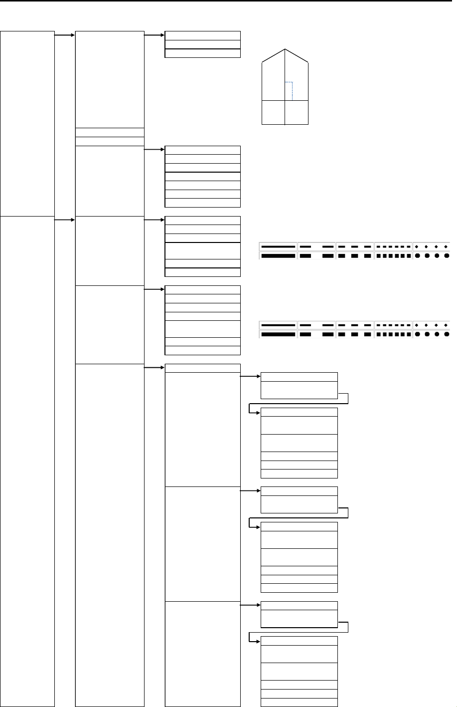
MDC-7000P/7900P Series Chapter 11 Appendix
0093169006-05E 11-5
NAV TOOL SHIP OUTLINE SHIP OUTLINE ⇒OFF, ON
CCRP ⇒1 to 4
OS PROFILE ⇒
HL BLINK ⇒OFF, ON
STERN LINE ⇒OFF, ON
BARGE ICON BARGE ICON ⇒OFF, ON
POSITION ⇒FWD, AFT
LENGTH ⇒0 to 511m
WIDTH ⇒0 to 511m
LINE NO. ⇒1 to 10
ROW NO. ⇒1 to 10
OFFSET ⇒0 to 511m
MAP OWN TRACK OWN TRACK ⇒OFF, ON
CLEAR ⇒CANCEL, GO
COLOR ⇒
STYLE ⇒
PLOT INT ⇒1sec, 2sec, 5sec, 10sec, 30sec, 1min, 3min
PLOT NUMBER ⇒1000, 2000, 4000, 5000, 7000, 10000, 20000
TARGET TRACK TARGE T TRA CK ⇒1 to 100
DISPLAY ⇒OFF, ON
CLEAR ⇒CANCEL, GO
COLOR ⇒
STYLE ⇒
PLOT INT ⇒OFF, 2sec, 15sec, 30sec, 1min, 3min, 5min
PLOT NUMBER ⇒50, 100, 200, 500, 1000
COAST LINE COAST LINE ⇒ALL, 1, 2, 3, 4, 5, 6, 7, 8, 9, 10, OFF
EDIT CURSOR (1 to 10) ⇒CANCEL, GO
BLOCK NUMBER
(1 to 10)
NUMBER
LAT ⇒90°00.000S
to 90°00.000N
LON ⇒180°00.000W
to 180°00.000E
COLOR ⇒8 colors
DIVIDE ⇒OFF, ON
SET
MOVE CURSOR (1 to 10) ⇒CANCEL, GO
BLOCK NUMBER
(1 to 10)
NUMBER ⇒1 to 100
LAT ⇒90°00.000S
to 90°00.000N
LON ⇒180°00.000W
to 180°00.000E
COLOR ⇒8 colors
DIVIDE ⇒OFF, ON
SET
ADD CURSOR (1 to 10) ⇒CANCEL, GO
BLOCK NUMBER
(1 to 10)
NUMBER ⇒1 to 100
LAT ⇒90°00.000S
to 90°00.000N
LON ⇒180°00.000W
to 180°00.000E
COLOR ⇒8 colors
DIVIDE ⇒OFF, ON
SET
8 colors
8 colors
Adx
dy
CD
B
OUTLINE
A0 − 511m
B 0 − 511m
C 0 − 63m
D 0 − 63m
ANT OFFSET
dx -63 −63m
dy -511 −511m

Chapter 11 Appendix MDC-7000P/7900P Series
0093169006-05E 11-6
MAP COAST LINE DELETE CURSOR (1 to 10) ⇒CANCEL, GO
BLOCK NUMBER
(1 to 10)
NUMBER ⇒1 to 100
LAT ⇒90°00.000S
to 90°00.000N
LON ⇒
SET
CLEAR BLOCK NUMBER
(1 to 10) ⇒CANCEL, GO
NAV LINE NAV LINE ⇒ALL, 1, 2, 3, 4, 5, 6, 7, 8, 9, 10, OFF
EDIT ⇒Same COAST LINE => EDIT
MOVE ⇒Same COAST LINE => MOVE
ADD ⇒Same COAST LINE => ADD
DELETE ⇒Same COAST LINE => DELETE
CLEAR ⇒Same COAST LINE => CLEAR
ROUTE ROUTE ⇒ALL, 1, 2, 3, 4, 5, 6, 7, 8, 9, 10, OFF
EDIT ⇒Same COAST LINE => EDIT
MOVE ⇒Same COAST LINE => MOVE
ADD ⇒Same COAST LINE => ADD
DELETE ⇒Same COAST LINE => DELETE
CLEAR ⇒Same COAST LINE => CLEAR
EVENT MKR EVENT MKR ⇒ALL, 1, 2, 3, 4, 5, 6, 7, 8, 9, 10, OFF
EDIT ⇒Same COAST LINE => EDIT
MOVE ⇒Same COAST LINE => MOVE
ADD ⇒Same COAST LINE => ADD
DELETE ⇒Same COAST LINE => DELETE
CLEAR ⇒Same COAST LINE => CLEAR
AREA AREA ⇒ALL, 1, 2, 3, 4, 5, 6, 7, 8, 9, 10, OFF
EDIT ⇒Same COAST LINE => EDIT
MOVE ⇒Same COAST LINE => MOVE
ADD ⇒Same COAST LINE => ADD
DELETE ⇒Same COAST LINE => DELETE
CLEAR ⇒Same COAST LINE => CLEAR
MONITORED ROUTE ⇒OFF, ON
WPT ID DISP ⇒OFF, ON
TARGET TRACK ID ⇒OFF, ON
DATUM ⇒W84, W72, S85, P90, TOY, 999
EDIT USER DATUM ⇒3 words
OFFSET ⇒EPFS, MAN
MAN OFFSET ⇒1.000S to 1.000N
⇒1.000W to 1.000E
GPS BUOY GPS BUOY ⇒OFF, ON
NUM DISP ⇒OFF, ON
WAT TEMP DISP ⇒OFF, ON
BLOCK NUMBER ⇒1 to 10
BLOCK CLEAR ⇒CANCEL, GO
BLOCK DATA
WPT FLAG ⇒OFF, ON
LAT/LON LINE ⇒OFF, ON
CHART ⇒OFF, ON
CHART DISP SET LAND FILL ⇒OFF, ON
PLACE NAME ⇒OFF, ON
LIGHTHOUSE ⇒OFF, ON
BUOY ⇒OFF, ON
FISH HAVEN/WRECK ⇒OFF, ON
TRAFFIC ROUTES ⇒OFF, ON
CAUTION AREA ⇒OFF, ON
FISHERY ⇒OFF, ON
CABLE ⇒OFF, ON
180°00.000W
to 180°00.000E
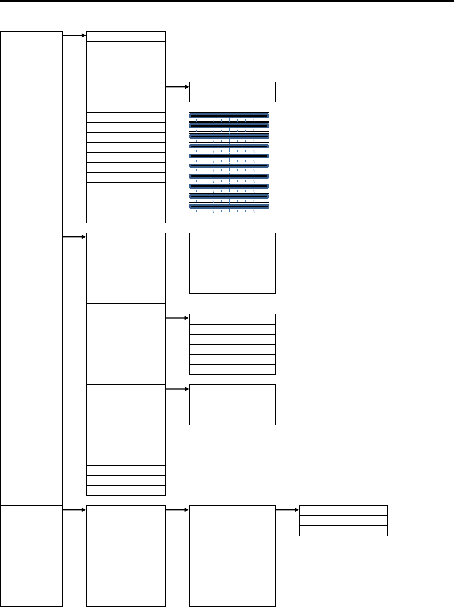
MDC-7000P/7900P Series Chapter 11 Appendix
0093169006-05E 11-7
BRILL ECHO ⇒YELLOW, GREEN
TRAIL ⇒BLUE, BROWN
BKGND PPI ⇒BLACK, BLUE
BKGND DATA ⇒BLACK, BLUE
DATA ⇒WHITE, GREY
OTHERS CHART LAND ⇒
DEPTH ⇒WHITE, BLUE
ECHO ⇒20 to 100
TRAIL ⇒20 to 100
BKGND ⇒20 to 100
OS/TOOL ⇒20 to 100
TGT ⇒20 to 100
MAP ⇒20 to 100
CURSOR ⇒20 to 100
DATA ⇒20 to 100
WARNING ⇒20 to 100
ALARM ⇒20 to 100
RESET ⇒CANCEL, GO
SYSTEM INTER-SWITCH ⇒INDEPENDENT MASTER
INDEPENDENT SLAVE
DUAL MASTER
DUAL SLAVE
CROSS
MONITOR
TIME ⇒UTC, LOCAL
USER USER 1 A ⇒CANCEL, GO
USER 2 B ⇒CANCEL, GO
USER 3 C ⇒CANCEL, GO
USER 4 D ⇒CANCEL, GO
EDIT USER NAME ⇒10 words
DEFAULT SETTING ⇒CANCEL, GO
SOUND SOUND ⇒OFF, ON
FREQUENCY ⇒1 to 8
KEY CLICK ⇒OFF, ON
EXT BUZZER ⇒OFF, CONTINUE
HELP ⇒OFF, ON
PROTECT MENU ⇒PROTECT CANCEL NUMBER (0000 to 9999)
MON ⇒OFF, ON
RX
TX
SYSTEM
MAINTENANCE STARTUP TUNE TUNE ⇒AUTO, MAN
AUTO ADJ ⇒0.0 to 100.0
MAN ADJ ⇒0.0 to 100.0
HL OFFSET ⇒-180.0 to 180.0°
TX DE LAY ⇒0.000 to 4.000
ANT HEIGHT ⇒0 to 100m
ANT CABLE ⇒0 to 100m
MBS ⇒0.000 to 2.000
SEA CURVE ⇒1 to 8
BROWN, GREEN, LIME, YELLOW, GREY
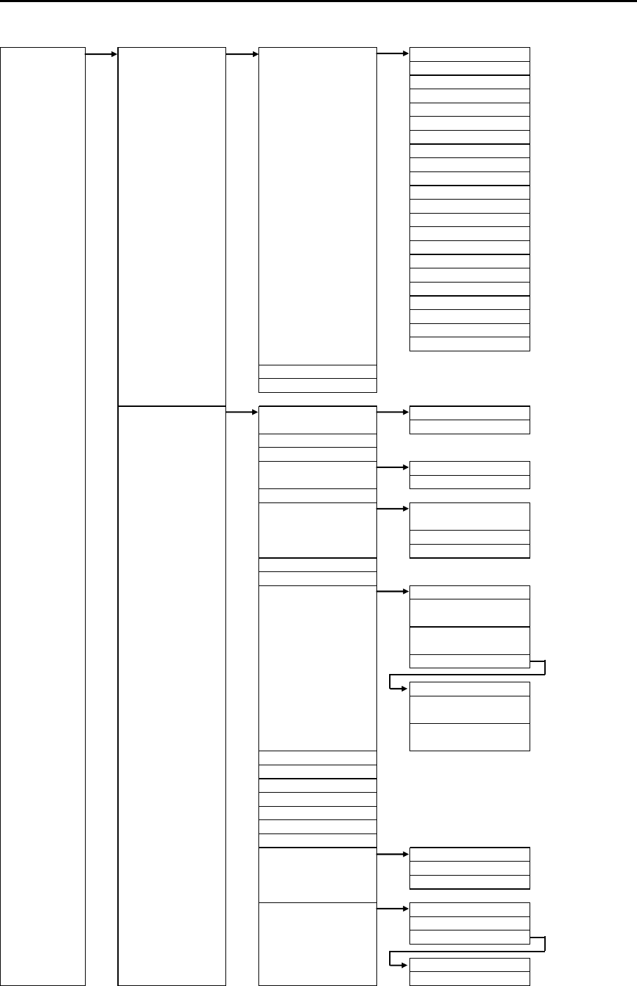
MDC-7000P/7900P Series Chapter 11 Appendix
0093169006-05E 11-9
MAINTENANCE STARTUP TIMES ENABLE 5sec ⇒OFF, ON
10sec ⇒OFF, ON
15sec ⇒OFF, ON
30sec ⇒OFF, ON
1min ⇒OFF, ON
2min ⇒OFF, ON
3min ⇒OFF, ON
5min ⇒OFF, ON
6min ⇒OFF, ON
10min ⇒OFF, ON
12min ⇒OFF, ON
15min ⇒OFF, ON
24min ⇒OFF, ON
30min ⇒OFF, ON
45min ⇒OFF, ON
48min ⇒OFF, ON
60min ⇒OFF, ON
2hr ⇒OFF, ON
4hr ⇒OFF, ON
8hr ⇒OFF, ON
16hr ⇒OFF, ON
24hr ⇒OFF, ON
⇒19 INCH, 23 INCH
⇒OFF, ON
I/O HDG HDG ⇒GYRO
OFFSET ⇒0.0 to 359.9°
GYRO
OFFSET
STW STW ⇒SDME, MAN
MAN ⇒0.0 to 100.0kn
DLOG
COG/SOG COG/SOG ⇒SDME, EPFS,
COG MAN ⇒0.0 to 359.9°
SOG MAN ⇒0.0 to 100.0kn
DLOG
DLOG
POSITION POSITION ⇒EPFS, MAN
LAT MAN ⇒90°00.000S
to 90°00.000N
LON MAN ⇒180°00.000W
to 180°00.000E
OFFSET
OFFSET ⇒EPFS, MAN
LAT MAN ⇒1.000S
to 1.000N
LON MAN ⇒1.000W
to 1.000E
DGPS
OFFSET
GPS
DATUM REF
LOCAL
SET/DRIFT SET/DRIFT ⇒SDME, MAN
SET MAN ⇒0.0 to 359.9°
DRIFT MAN ⇒0.0 to 100.0kn
TIME TIME ⇒EPFS, CLOCK
TIME ZONE ⇒-14:30 to 14:30
CLOCK SET
DATE ⇒DD/MM/YY
TIME ⇒00:00 to 23:59
MAN, CURRENT
MONITOR SIZE
FERRY MENU
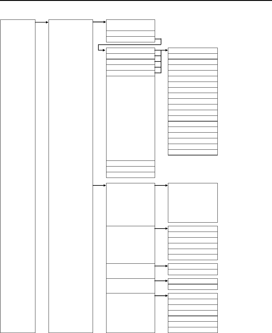
Chapter 11 Appendix MDC-7000P/7900P Series
0093169006-05E 11-10
MAINTENANCE I/O GPS
TIME ZONE
OUTPUT
OUTPUT NAV DTM ⇒0.0 to 10.0sec
OUTPUT EPFS EVE ⇒0.0 to 10.0sec
OUTPUT SDME GLL ⇒0.0 to 10.0sec
OUTPUT GYRO HBT ⇒0.0 to 10.0sec
OUTPUT OTHER HDT ⇒0.0 to 10.0sec
OSD ⇒0.0 to 10.0sec
POS ⇒0.0 to 10.0sec
ROT ⇒0.0 to 10.0sec
RSD ⇒0.0 to 10.0sec
THS ⇒0.0 to 10.0sec
TLB ⇒0.0 to 10.0sec
TLL ⇒0.0 to 10.0sec
TTD ⇒0.0 to 10.0sec
TTM ⇒0.0 to 10.0sec
VBW ⇒0.0 to 10.0sec
VDR ⇒0.0 to 10.0sec
VHW ⇒0.0 to 10.0sec
VTG ⇒0.0 to 10.0sec
ZDA ⇒0.0 to 10.0sec
TLL OUT ⇒TT, MARK, TARGET
ALR OUT PORT ⇒NAV, EPFS, SDME, GYRO, OTHER
ALF OUT PORT ⇒NAV, EPFS, SDME, GYRO, OTHER
INPUT BWC, DBT, DPT, DTM,
GGA, GLC, GLL, GNS,
HBT, HDG, HDM, HDT,
MTW, RMA, RMB, RMC, ⇒ALL, NAV, EPFS,
ROT, RTE, THS, VBW, SDME, GYRO, OTHER
VDR, VHW, VTG, WPL,
XTE , ZDA
FORMAT NAV ⇒
EPFS ⇒
SDME ⇒
GYRO ⇒
OTHER ⇒
AUTO SETUP ⇒CANCEL, GO
KGC SET INITIAL ⇒CANCEL, GO
BRG CORR ⇒0.0 to 359.9°
JB-35 SET JB-35 ⇒OFF, ON
INITIAL ⇒CANCEL, GO
SERIAL MONITOR NAV ⇒Monitor
EPFS ⇒Monitor
SDME ⇒Monitor
GYRO ⇒Monitor
OTHER ⇒Monitor
AIS ⇒Monitor
ALL ⇒Monitor
61162-1, 61162-2
61162-1, 61162-2
61162-1, 61162-2
61162-1, 61162-2
61162-1, 61162-2

MDC-7000P/7900P Series Chapter 11 Appendix
0093169006-05E 11-11
MAINTENANCE SECTOR MUTE MUTE ⇒OFF, ON
START ⇒0 to 359°
END ⇒0 to 359°
PRESET RAIN MIN ⇒0 to 4095
RAIN MAX ⇒0 to 4095
SEA MIN ⇒0 to 4095
SEA MAX ⇒0 to 4095
GAIN MIN ⇒0 to 4095
GAIN MAX ⇒0 to 4095
GAIN OFFSET ⇒0 to 4095
SEA OFFSET ⇒0 to 4095
BACKUP SETUP LOAD ⇒CANCEL, GO
SETUP SAVE ⇒CANCEL, GO
SD CARD SETUP LOAD ⇒CANCEL, GO
SETUP SAVE ⇒CANCEL, GO
MARK LOAD ⇒CANCEL, GO
MARK SAVE ⇒CANCEL, GO
TGT TRACK LOAD ⇒CANCEL, GO
TGT TRACK SAVE ⇒CANCEL, GO
OWN TRACK LOAD ⇒CANCEL, GO
OWN TRACK SAVE ⇒CANCEL, GO
PARAMETER RESET ⇒CANCEL, GO
MAP/PAST RESET ⇒CANCEL, GO
BITE ALARM TEST ⇒OFF, ON
PANEL TEST
DIAGNOSE TT
DIAGNOSE AIS
SERIAL MONITOR NAV ⇒Monitor
EPFS ⇒Monitor
SDME ⇒Monitor
GYRO ⇒Monitor
OTHER ⇒Monitor
AIS ⇒Monitor
ALL ⇒Monitor
ANT MONITOR
SD CARD
TOTAL HOUR ⇒CANCEL, RESET
TX HOUR ⇒CANCEL, RESET
MENU SETUP ⇒CANCEL, GO
PASSWORD ⇒0000 to 9999
MON ⇒OFF, ON
RX
TX
SYSTEM
TUNE
CALIBRATION ⇒CANCEL, GO
VERSION ⇒MRD/MRM-108P KM-F44 xx.xx
MRO-108P KM-F45 yy.yy
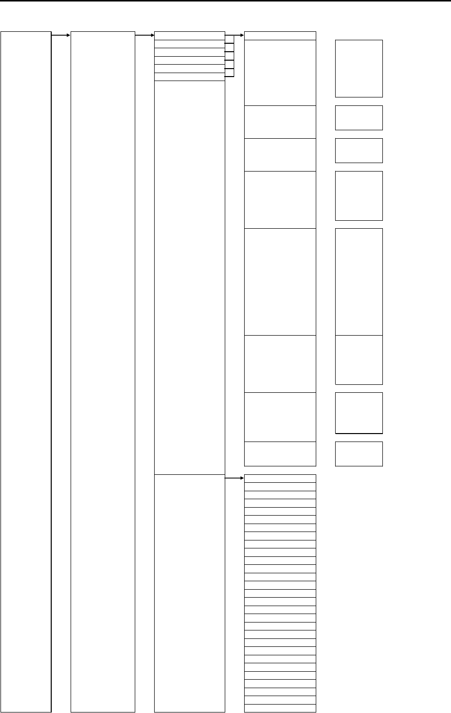
Chapter 11 Appendix MDC-7000P/7900P Series
0093169006-05E 11-8
MAINTENANCE STARTUP FUNCTION KEY F1 OFF
F2 ECHO ⇒
F3 PROCESS
F4 EXPANSION
F5 IR
F6 VID
NOISE REJ
SART
TRAIL ⇒TRAIL T/REL
TRAIL TIME
TRAIL RESET
DISPLAY ⇒STAB MODE
TM RESET
C UP RESET
ALARM ⇒
TARGET ⇒VECT T/REL
VECT TIME
CPA/TCPA
AIS
TT DELETE
TT REF ACQ
NAV TOOL ⇒RR
BRG T/REL
GUARD LINE
SHIP OUTLINE
STERN LINE
BARGE ICON
MAP ⇒OWN TRACK
MAP DISP
EVENT OWN
SYSTEM ⇒TIME
TGT LIST SORT
RANGE ENABLE ⇒OFF, ON
⇒OFF, ON
⇒OFF, ON
0.5 ⇒OFF, ON
⇒OFF, ON
1⇒OFF, ON
1.5 ⇒OFF, ON
2⇒OFF, ON
3⇒OFF, ON
4⇒OFF, ON
5⇒OFF, ON
6⇒OFF, ON
8⇒OFF, ON
10 ⇒OFF, ON
12 ⇒OFF, ON
16 ⇒OFF, ON
20 ⇒OFF, ON
24 ⇒OFF, ON
32 ⇒OFF, ON
36 ⇒OFF, ON
40 ⇒OFF, ON
48 ⇒OFF, ON
50 ⇒OFF, ON
64 ⇒OFF, ON
80 ⇒OFF, ON
96 ⇒OFF, ON
100 ⇒OFF, ON
120 ⇒OFF, ON
144 ⇒OFF, ON
GUA RD Z ONE EDIT
PICTURE MODE
ECHO ALARM
ECHO ALARM EDIT
MAP AREA ALARM
GUARD ZONE
0.0625
NAV LINE CROSS
PAST POSN T/REL
PAST POSN TIME
AUTO AC Q AREA
AUTO ACQ AREA EDIT
OS PAST TRK RESET
TT ALL DELETE
ACQ
TARGET TRACK
EVENT CURSOR
ASSISTANT DISP
0.125
0.25
0.75

Chapter 11 Appendix MDC-7000P/7900P Series
0093169006-05E 11-12
11.2 Input data
11.2.1 Validity and integrity of input data
Data
indication
HDG Latitude and
Longitude
SPD COG/SOG WP
White color THS-A*
HDT
GLL-A,D*
GGA-1,2,3,4,5**
GNS-A,D,F,P,R*
VBW
Status water speed
: A
VHW
VBW
Status ground
speed: A
VTG-A,D,P*
RMB-A,D*
BWC-A,D*
RTE/WPL
Yellow color EPFS has output of GBS which is fault detection as well as GLL, GGA, GNS, VTG, RMB, BWC
and WPL.
In case Expected error of GBS sentence exceeds 10 m, LAT/LON, COG/SOG will be low integrity.
At this time, numerical values of LAT/LON and COG/SOG displayed at the upper right of display
are shown in yellow.
Orange
color and
XXX.XX
THS-E,M,S,V*
HDT(no input)
GLL-E,M,S,N*
GGA-0,6,7,8**
GNS-E,M,N,S*
VBW
Status water speed
: V
VHW(no input)
VBW
Status ground
speed: V
VTG-E,M,S,N*
RMB-E,M,S,N*
BWC-E,M,S,N*
RTE/WPL
(no input)
* mark is the "Mode indicator" in the data string. Refer to 11.2.2 Details of the data input format.
** mark is the "quality indicator" in the data string. Refer to 11.2.2 Details of the data input format.
11.2.2 Details of the data input format
Check sum: All the data from $ to the check sum position * is calculated by exclusive-OR operation and
used as checksum.
Heading
THS True heading and status
a*hh<CR><LF>
Note* mode indicator
Check su
m
A=Autonomous valid
Mode indicator* E=Estimated invalid
Heading, degrees true M=Manual input invalid
S=Simulator mode invalid
Note for IMO mode V=Data not valid invalid
II, IN, HE, HN, HC, GA, GP, GL, GN and SN are accepted.
HDT Heading true
T*hh<CR><LF>
Check su
m
Heading, degrees true
Note for IMO mode
II, IN, HE, HN, HC, GA, GP, GL, GN and SN are accepted.
$-- THS, x. x,
$-- HDT, x.x,
Note: HDG, HDM, VTG, RMC and RMA sentences are not accepted for IMO radar.
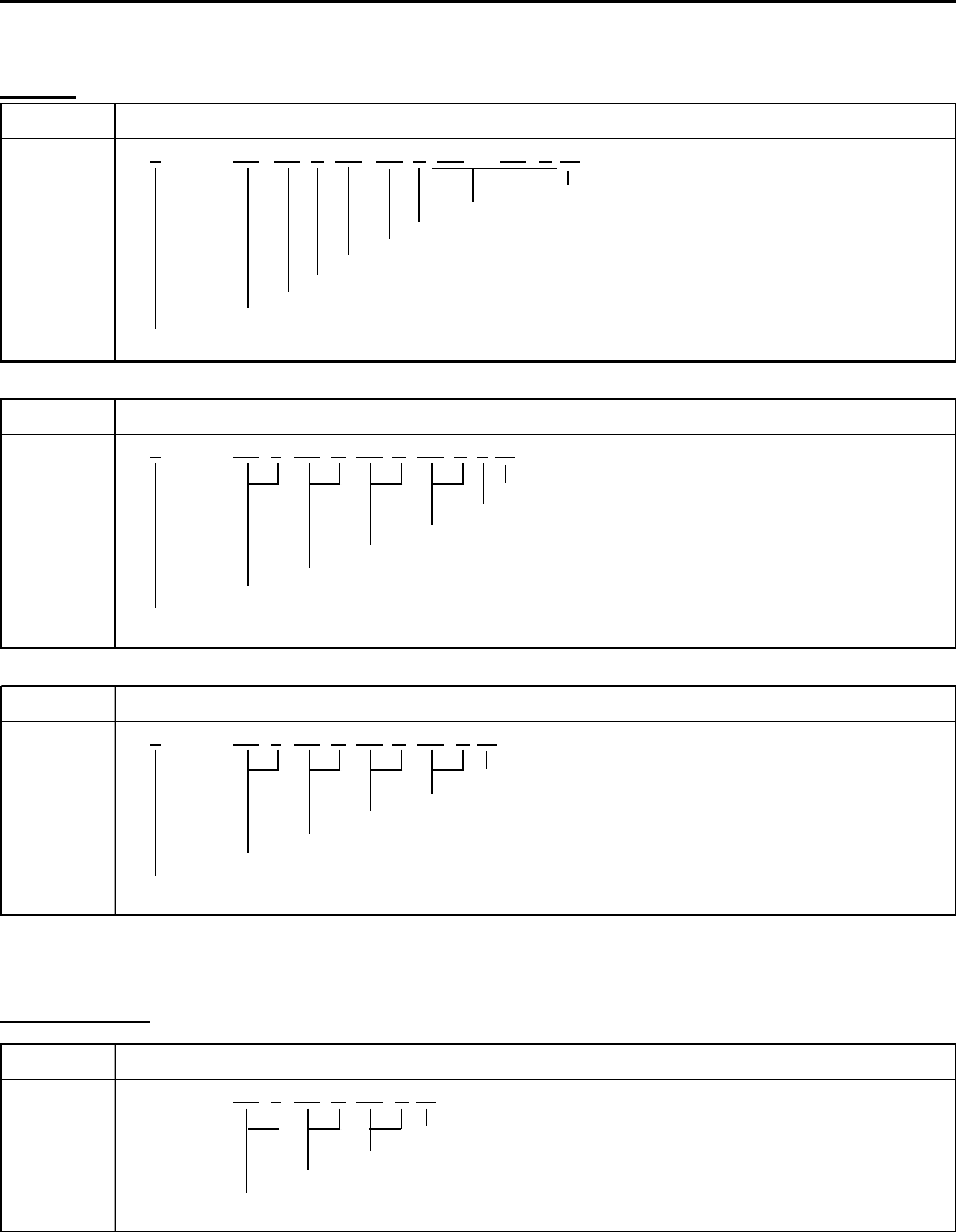
MDC-7000P/7900P Series Chapter 11 Appendix
0093169006-05E 11-13
Speed
VBW Dual ground/water speed
A*hh<CR><LF>
Ch
ec
k
su
m
Th
ese
fi
e
ld
s are no
t
use
d
S
tatus groun
d
spee
d
,
A
=
V
a
lid
,
V
=
I
nva
lid
T
ransverse groun
d
spee
d
,
k
nots
L
ong
i
tu
di
na
l
groun
d
spee
d
,
k
nots
S
tatus w ater spee
d
,
A
=
V
a
lid
,
I
nva
lid
T
ranverse w aterspee
d
,
k
nots
L
ong
i
tu
di
na
l
w ater spee
d
,
k
nots
N
ote
f
or
IMO
mo
d
e
II
,
IN
,
VD
,
GA
,
GP
,
GL
,
GN
,
SN
,
VM
an
d
VW
are accep
t
e
d
.
VTG Course over ground and ground speed
a*hh<CR><LF>
Chec k s u
m
Mode indicator A/P/D=Valid, E/M/S/N=Invalid
Speed over ground, km/h
Speed over ground, knots
Course over ground, degrees magnetic
Course over ground, degrees true
Note for IMO mode
II, IN, VD, GA, GP, GL, GN, SN, VM and VW are accepted.
VHW Water speed and heading
K*hh<CR><LF>
Chec k s u
m
Speed, km/h
Speed, knots
Heading, degrees magnetic
Heading, degrees true
Note for IMO mode
II, IN, VD, GA, GP, GL, GN, SN, VM and VW are accepted.
x.x,
M
,x.x,N,x.x,$--VHW, x.x,T,
A
,x.x,
$-- VTG, x.x,T,x.x,
M
,x.x,N,x.x,K,
A
,x.x,x.x,
A
,x.x,$--VBW, x.x,x.x,
Set and Drift
VDR Set and drift
N*hh<CR><LF>
Chec k s u
m
Current speed, knots
Direction, degrees magnetic
Direction, degrees true
$-- VDR, x.x,T,x.x,
M
,x.x,
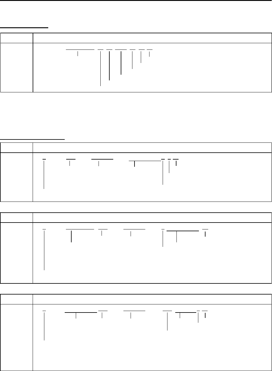
Chapter 11 Appendix MDC-7000P/7900P Series
0093169006-05E 11-14
ZDA Time and date
xx*hh<CR><LF>
UTC Check su
m
Local zone minutes (00 to +59)
Local zone hours (00 h to +/-13 h)
Year (UTC)
Month , 01 to 12 (UTC)
Day, 01 to 31 (UTC)
xx, xxxx,xx,$ -- ZDA, hhmmss.ss,xx,
Time and date
Note: RMC and GGA sentences are not accepted for IMO radar.
Latitude/Longitude
GLL Geographic position – Latitude/longitude
a*hh<CR><LF>
Note* Mode indicator
Latitude Longitude UTC is not used Check su
m
A=Autonomous (Valid)
Mode indicator* D=Diff erential (V alid)
E=Estimated (Invalid)
Status M=Manual input (Ivalid)
Note for IMO mode A: Data valid S=Simulator (Invalid)
II, IN, GA, GP, GL, GN, SN and LC are accepted. V: Data invalid N=Data not valid
GGA Global positioning system (GPS) fix data
Latitude Longitude Check su
m
UTC of position These field is not used.
GPS quality indicator 1/2/3/4/5=Valid, 0/6/7/8=Invalid
0=Fix not invalid or invalid
1=GPS SPS mode 5=Fl oat RTK
2=Differential GPS, SPS mod
e
6=Estimated mode
Note for IMO mode
3=GPS PPS mode 7=M anual input mode
II, IN, GA, GP, GL, GN and SN are accepted.
4=Real time Kinematic 8=Simulator mod
e
GNS GNSS fix data
a*hh<CR><LF>
Not used Latitude Longitude Not used Check su
m
N/S E/W Navigation status indicator
Mode indicator S=Safe
A /D/P/R/ F=V alid C=Cautio n
Note f or IMO mode E/M/S/N=Inv alid U=Uns af e
GN, GP, GL and GA are accepted. GN, GP: first character V=Navigational status not used
GL: second character
GA: third character
yyyyy.yy, E/W,a,
, , , , , , ,
*hh<CR><LF>
$--GNS, hhmmss.ss, llll.ll, N/S, yyyyy.yy, E/W, c--c, , , , , , ,
$--GGA, hhmmss.ss, llll.ll, N/S,
$-- GLL, llll.ll, N/S, yyyyy.yy, E/W, hhmmss.ss,
A
,
Note: RMA and RMC sentences are not accepted for IMO radar.
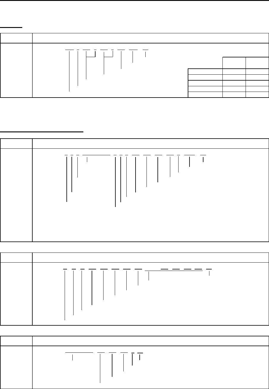
MDC-7000P/7900P Series Chapter 11 Appendix
0093169006-05E 11-15
Datum
DTM Datum reference
Chec k s u
m
Reference datum
Altitude offset, m WGS84
Lon offset min, E/W WGS72
Lat offset min, N/S SGS85
Local datum subdivision code PE90
Local datum User defined
$ -- DTM, ccc,a,x.x,a,x.x,a,x.x,ccc *hh<CR><LF>
W72 W72
S85 S85
P90 P90
Reference Local
datum
datu
m
W84 W84
-999
Alarm and alert handling
ALF Alert sentence
Ti
me o
f
l
ast
Ch
ec
k
su
m
c
h
ange
Al
ert text
E
sca
l
a
ti
on coun
t
er,
0
t
o
9
S
equent
i
a
l
R
ev
i
s
i
on counter,
1
to
99
message
Al
ert
i
nstance,
1
to
999999
id
ent
if i
er,
0
to
9
Al
ert
id
ent
if i
er
S
entence
M
anu
f
acturer mnemon
i
c co
d
e
num
b
er,
1
to
2
Al
ert state,
A
,
S
,
N
,
O
,
U
or
V**
T
ota
l
num
b
er o
f
ALF
sentences
Al
ert pr
i
or
i
ty,
E
,
A
,
W
or
C*
f
or t
hi
s message,
1
to
2
Al
ert category,
A
,
B
or
C
N
ote
**
Al
ert state
V
=
A
c
ti
ve-
U
nac
k
now
l
e
d
ge
N
o
t
e
*
Al
er
t
pr
i
or
it
y
S
=
A
c
ti
ve-
Sil
ence
d
E
=
E
mergency
Al
erm
(f
or use w
i
t
h
B
r
id
ge
Al
ert
M
anagement
)
A
=
A
ct
i
ve-
A
c
k
now
l
e
d
ge or act
i
ve
A
=
Al
arm
O
=
A
ct
i
ve-
R
espons
ibili
ty trans
f
erre
d
W
:
W
arn
i
ng
U
=
R
ect
if i
e
d
-
U
nac
k
now
l
e
d
ge
C
=
C
aut
i
on
N
=
N
orma
l
ALC Cyclic alert list
ALC,
Ch
ec
k
su
m
Addi
t
i
ona
l
Al
ert entr
i
es
R
ev
i
s
i
on counter
Al
ert entry
1
Al
er
t
i
ns
t
ance
Al
ert
id
ent
if i
er
M
anu
f
acturer mnemon
i
c co
d
e
N
um
b
er o
f
a
l
ert entr
i
es
S
equent
i
a
l
message
id
ent
if i
er,
00
to
99
S
entence num
b
er,
01
to
99
T
ota
l
num
b
er o
f
sentences
f
or t
hi
s message,
01
to
99
ARC Alert command refused
c*hh<CR><LF>
Reles e time Chec k s u
m
Note*
Refused alert command, A, Q, O or S* A: Acknowl edg e
Alert instance, 1 to 999999 Q: Request / repeat information
Alert identifier O: Responsibili ty transfer
Manuf acturer mnemonic code S: Si lence
x.x,……, aaa,x.x,x.x,x.x*hh<CR><LF>
$ -- ARC, hhmmss.ss,aaa,x.x,x.x,
$ -- xx,xx,xx,x.x,aaa,x.x,x.x,
$ -- ALF, x,x,x, hhmmss.ss,a,a,a,aaa,x.x,x.x,x.x,x, c---c *hh<CR><LF>
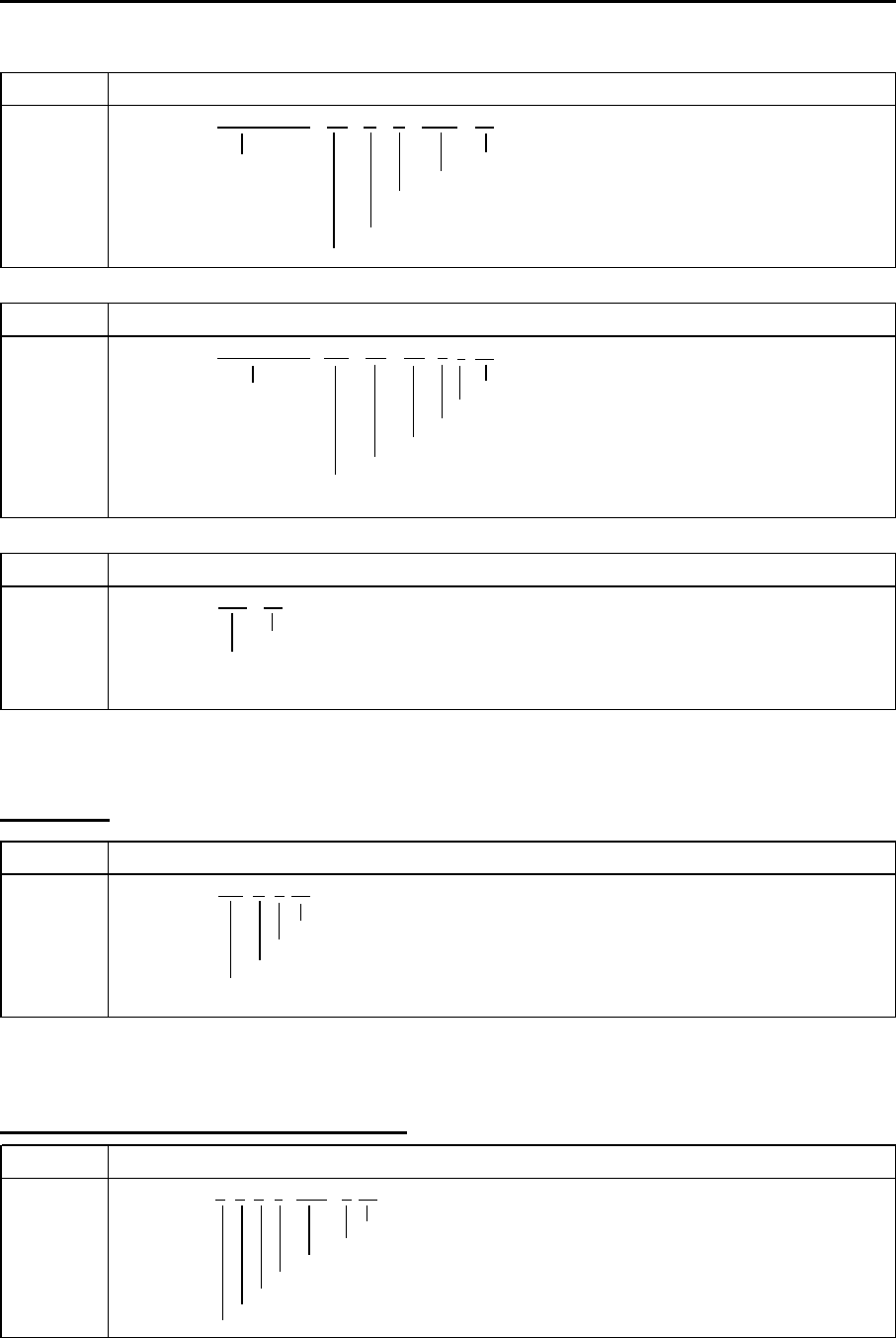
Chapter 11 Appendix MDC-7000P/7900P Series
0093169006-05E 11-16
ALR Set alarm state
Time of alarm Check su
m
condition Alarm's description text
change, UTC Alarm's acknow ledge state, A=acknow ledged
V=unacknow ledged
Alarm condition (A=threshold exceeded, V=not exceeded)
Unique alarm number (identifier) at alarm source
ACN Alert command
a*hh<CR><LF>
Reles e time Chec k s u
m
Sentence status flag: "C"
Alert command, A, Q, O or S* Note* Alert command
Alert instance, 1 to 999999 A: Acknow ledge
Alert identifier Q: Request / repeat information
manufacture mnemonic code O: Responsibility transfer
S: Silence
ACK Acknowledge alarm
Check su
m
Unique alarm number (identifier) at alarm source
*hh<CR><LF>A,A, c---c$ -- ALR, hhmmss.ss,
xxx,
x.x,x.x,c,
$ -- ACK, xxx *hh<CR><LF>
$ -- ACN, hhmmss.ss,
aaa,
Heartbeat
HBT Heartbeat supervision sentence
x*hh<CR><LF>
Chec k s u
m
Sequential sentence identifier
Equipment status A=Yes, V=No
Configured repeat interval
$-- HBT, x.x,
A
,
AIS target and own ship information
VDM AIS VHF data-link message
x*hh<CR><LF>
Ch
ec
k
su
m
N
um
b
er o
f
fill
-
bi
ts,
0
to 5
E
ncapsu
l
ate
d
ITU
-
R
M
.
13
7
1
ra
di
o message
(M
essage part,
6bi
t
fi
e
ld
s
)
AIS
c
h
anne
l
(A/B)
M
essage num
b
er,
1
to
9
S
en
t
ence num
b
er,
1
t
o
9
T
ota
l
num
b
er o
f
sentences nee
d
e
d
to trans
f
er t
h
e message,
1
to
9
!-- VDM,x,x,x,a,s--s,
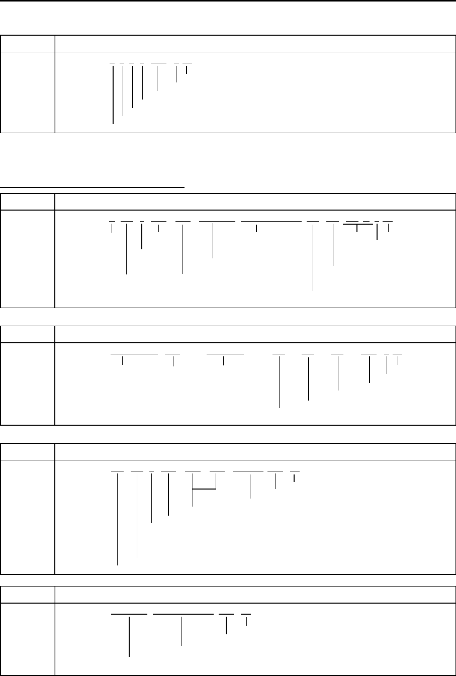
MDC-7000P/7900P Series Chapter 11 Appendix
0093169006-05E 11-17
VDO AIS VHF data-link own-vessel report
x*hh<CR><LF>
Ch
ec
k
su
m
N
um
b
er o
f
fill
-
bi
ts,
0
to 5
E
ncapsu
l
ate
d
ITU
-
R
M
.
13
7
1
ra
di
o message
(M
essage part,
6bi
t
fi
e
ld
s
)
AIS
c
h
anne
l
(A/B)
M
essage num
b
er,
1
to
9
S
en
t
ence num
b
er,
1
t
o
9
T
ota
l
num
b
er o
f
sentences nee
d
e
d
to trans
f
er t
h
e message,
1
to
9
s--s,!-- VDO,x,x,x,a,
Waypoint Latitude/Longitude, ID
RMB Recommended minimum navigation information
a*hh<CR><LF>
S
tatus
N
ot use
d
D
est
i
nat
i
on
N
ot use
d
Ch
ec
k
su
m
A
=
V
a
lid
waypo
i
n
t
l
ong
it
u
d
e,
M
o
d
e
i
n
di
ca
t
or
V
=
D
a
t
a
Di
rec
ti
on
E/W
A/D
=va
lid
I
nva
lid
to steer
D
est
i
nat
i
on w aypo
i
nt
E/M/S/ N
=
i
nva
lid
L/R
l
at
i
tu
d
e,
N/S
B
ear
i
ng to
C
ross trac
k
D
est
i
nat
i
on w aypo
i
nt
ID
d
est
i
nat
i
on,
error
d
egrees nat
i
ca
l
m
il
es
R
ange to
d
est
i
nat
i
on,
naut
i
ca
l
m
il
es
BWC Bearing and distance to waypoint – Great circle
a*hh<CR><LF>
UTC
o
f
W
aypo
i
nt
W
aypo
i
nt
Ch
ec
k
su
m
o
b
servat
i
on
l
at
i
tu
d
e
l
ong
i
t
i
u
d
e
M
o
d
e
i
n
di
cator
*
N/S
E/W
W
aypo
i
nt
ID
Di
s
t
ance, nau
ti
ca
l
m
il
es
N
ote
*
M
o
d
e
i
n
di
cator
B
ear
i
ng,
di
grees magnet
i
c
A/D
=
V
a
lid
B
ear
i
ng,
di
grees true
E/M/ S / N
=
I
nva
lid
RTE Routes
*hh<CR><LF>
Ch
ec
k
su
m
waypo
i
nt
"
n
"
id
ent
if i
er
Addi
t
i
ona
l
waypo
i
nt
id
ent
if i
ers
W
aypo
i
nt
id
ent
ifi
re
(FROM
,
TO)
R
oute
id
ent
if i
er
M
essage mo
d
e
C
=comp
l
ete route, a
ll
waypo
i
nts
W
=w or
ki
ng route,
fi
rst
li
ste
d
waypo
i
nt
i
s
"FROM"
secon
d
i
s
"TO"
an
d
rema
i
n
i
ng are rest o
f
route
S
entence num
b
er
T
ota
l
num
b
er o
f
sentences
c--c,
$-- RTE, x.x
,x.x,a,c--c, c--c,c--c, . . . . . . c--c
x.x,x.x,x.x,
A
,
$ --
BWC,
hhmmss.ss, llll.ll, N/S, yyyyy.yy, E/W, x.x,T,x.x,
M
,x.x,N,
a,c--c, c--c, llll.ll, N/S, yyyyy.yy, E/W,$-- RMB,
A
,x.x,
WPL Waypoint location
*hh<CR><LF>
Chec k s u
m
Waypoint identifier
Waypoint longitude, E/
W
Waypoint latitude, N/S
c--c$ -- WPL, llll.ll, N/S, yyyyy.yy, E/W,
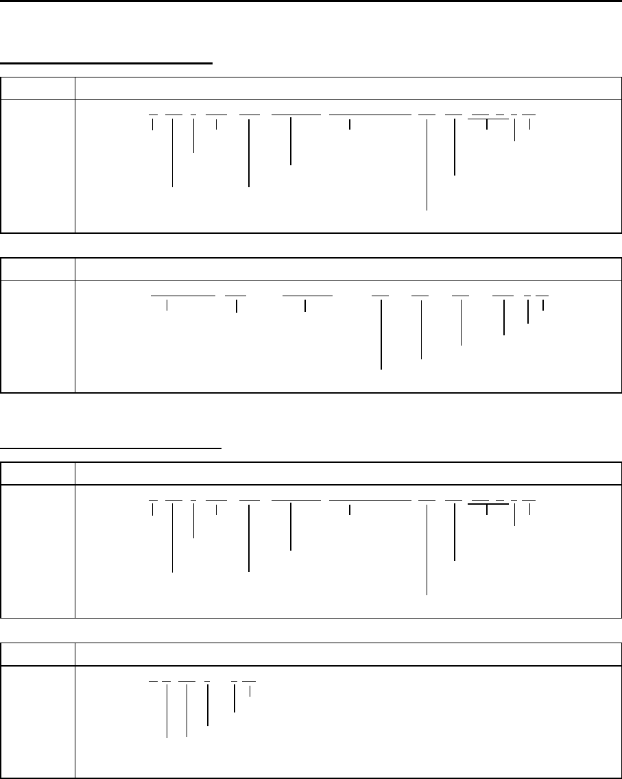
Chapter 11 Appendix MDC-7000P/7900P Series
0093169006-05E 11-18
Waypoint Bearing/Distance
RMB Recommended minimum navigation information
a*hh<CR><LF>
St
a
t
us
N
o
t
use
d
D
es
ti
na
ti
on
N
o
t
use
d
Ch
ec
k
su
m
A
=
V
a
lid
waypo
i
nt
l
ong
i
tu
d
e,
M
o
d
e
i
n
di
cator
V
=
D
ata
Di
rect
i
on
E/W
A/D
=va
lid
I
nva
lid
to steer
D
est
i
nat
i
on w aypo
i
nt
E/M/S/ N
=
i
nva
lid
L/R
l
at
i
tu
d
e,
N/S
B
ear
i
ng to
C
ross trac
k
D
est
i
nat
i
on w aypo
i
nt
ID
d
est
i
nat
i
on,
error
d
egrees nat
i
ca
l
m
il
es
R
ange
t
o
d
es
ti
na
ti
on,
naut
i
ca
l
m
il
es
BWC Bearing and distance to waypoint – Great circle
a*hh<CR><LF>
UTC
o
f
W
aypo
i
nt
W
aypo
i
nt
Ch
ec
k
su
m
o
b
servat
i
on
l
at
i
tu
d
e
l
ong
i
t
i
u
d
e
M
o
d
e
i
n
di
cator
*
N/S
E/W
W
aypo
i
nt
ID
Di
stance, naut
i
ca
l
m
il
es
N
o
t
e
*
M
o
d
e
i
n
di
ca
t
or
B
ear
i
ng,
di
grees magne
ti
c
A/D
=
V
a
lid
B
ear
i
ng,
di
grees true
E/M/ S / N
=
I
nva
lid
x.x,N, c--c,yyyyy.yy, E/W, x.x,T,x.x,
M
,$ --
BWC,
hhmmss.ss, llll.ll, N/S,
yyyyy.yy, E/W,x.x,x.x,x.x,
A
,$-- RMB,
A
,x.x,a,c--c, c--c, llll.ll, N/S,
Cross-track error, measured
RMB Recommended minimum navigation information
a*hh<CR><LF>
St
a
t
us
N
o
t
use
d
D
es
ti
na
ti
on
N
o
t
use
d
Ch
ec
k
su
m
A
=
V
a
lid
waypo
i
nt
l
ong
i
tu
d
e,
M
o
d
e
i
n
di
cator
V
=
D
ata
Di
rect
i
on
E/W
A/D
=va
lid
I
nva
lid
to steer
D
est
i
nat
i
on w aypo
i
nt
E/M/S/ N
=
i
nva
lid
L/R
l
at
i
tu
d
e,
N/S
B
ear
i
ng to
C
ross trac
k
D
est
i
nat
i
on w aypo
i
nt
ID
d
est
i
nat
i
on,
error
d
egrees nat
i
ca
l
m
il
es
R
ange
t
o
d
es
ti
na
ti
on,
naut
i
ca
l
m
il
es
XTE Cross-track error, measured
a*hh<CR><LF>
Chec k s u
m
Mode indicator A /D=Valid, E/M/S/N=Invalid
Direction to steer, L/R
Magnitude of cross-track error
Status: A=data valid, V=LORAN-C cycle lock w arning flag
Status: A=data valid, V=invalid
A
,
$-- XTE,
A
,
A
,x.x,a,N,
$-- RMB,
A
,x.x,a,c--c, c--c, llll.ll, N/S, yyyyy.yy, E/W,x.x,x.x,x.x,
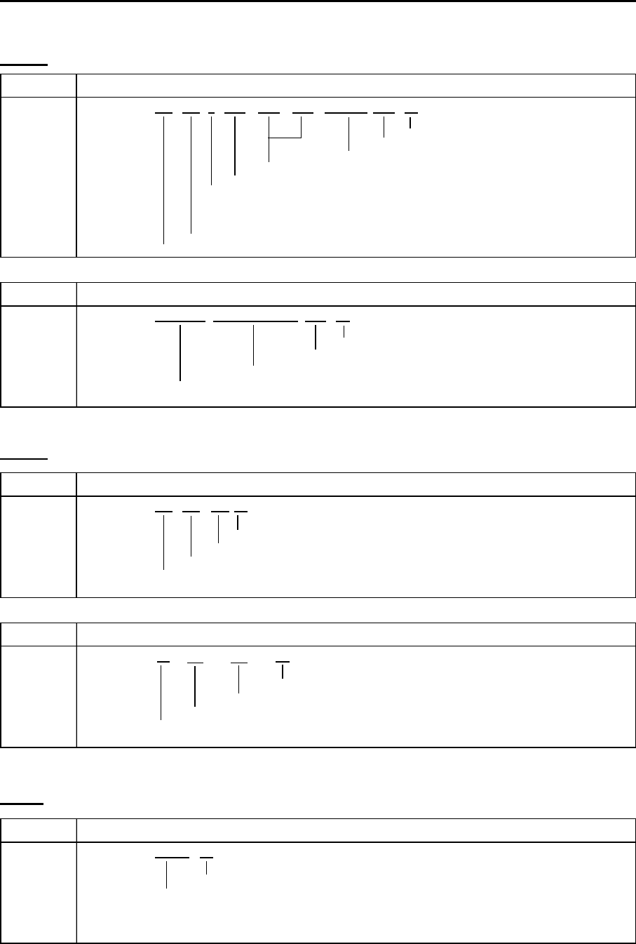
MDC-7000P/7900P Series Chapter 11 Appendix
0093169006-05E 11-19
Route
RTE Routes
*hh<CR><LF>
Ch
ec
k
su
m
waypo
i
nt
"
n
"
id
ent
if i
er
Addi
t
i
ona
l
waypo
i
nt
id
ent
if i
ers
W
aypo
i
nt
id
ent
ifi
re
(FROM
,
TO)
R
oute
id
ent
if i
er
M
essage mo
d
e
C
=comp
l
ete route, a
ll
waypo
i
nts
W
=w or
ki
ng rou
t
e,
fi
rs
t
li
s
t
e
d
waypo
i
n
t
i
s
"FROM"
secon
d
i
s
"TO"
an
d
rema
i
n
i
ng are rest o
f
route
S
entence num
b
er
T
ota
l
num
b
er o
f
sentences
WPL Waypoint location
*hh<CR><LF>
Chec k s u
m
Waypoint identifier
Waypoint longitude, E/
W
Waypoint latitude, N/S
c--c
$ -- WPL, llll.ll, N/S, yyyyy.yy, E/W,c--c
a, c--c, c--c,c--c, . . . . . .$-- RTE, x.x,x.x,
Depth
DPT Depth
Chec k s u
m
Maximum range scale in use
Offset from transducer, in metres
Water depth relative to the transducer, in metres
DBT Depth below transduce
r
Chec k s u
m
Water depth, fathoms
Water depth, m
Water depth, feet
x.x*hh<CR><LF>
$ -- DBT,
x.x, f,
x.x, M, x.x, F
*hh<CR><LF>
$ -- DPT, x.x,x.x,
Temp
MTW Water temperature
*hh<CR><LF>
Chec k s u
m
Temperature, degrees C
$--
MTW,
x.x, C
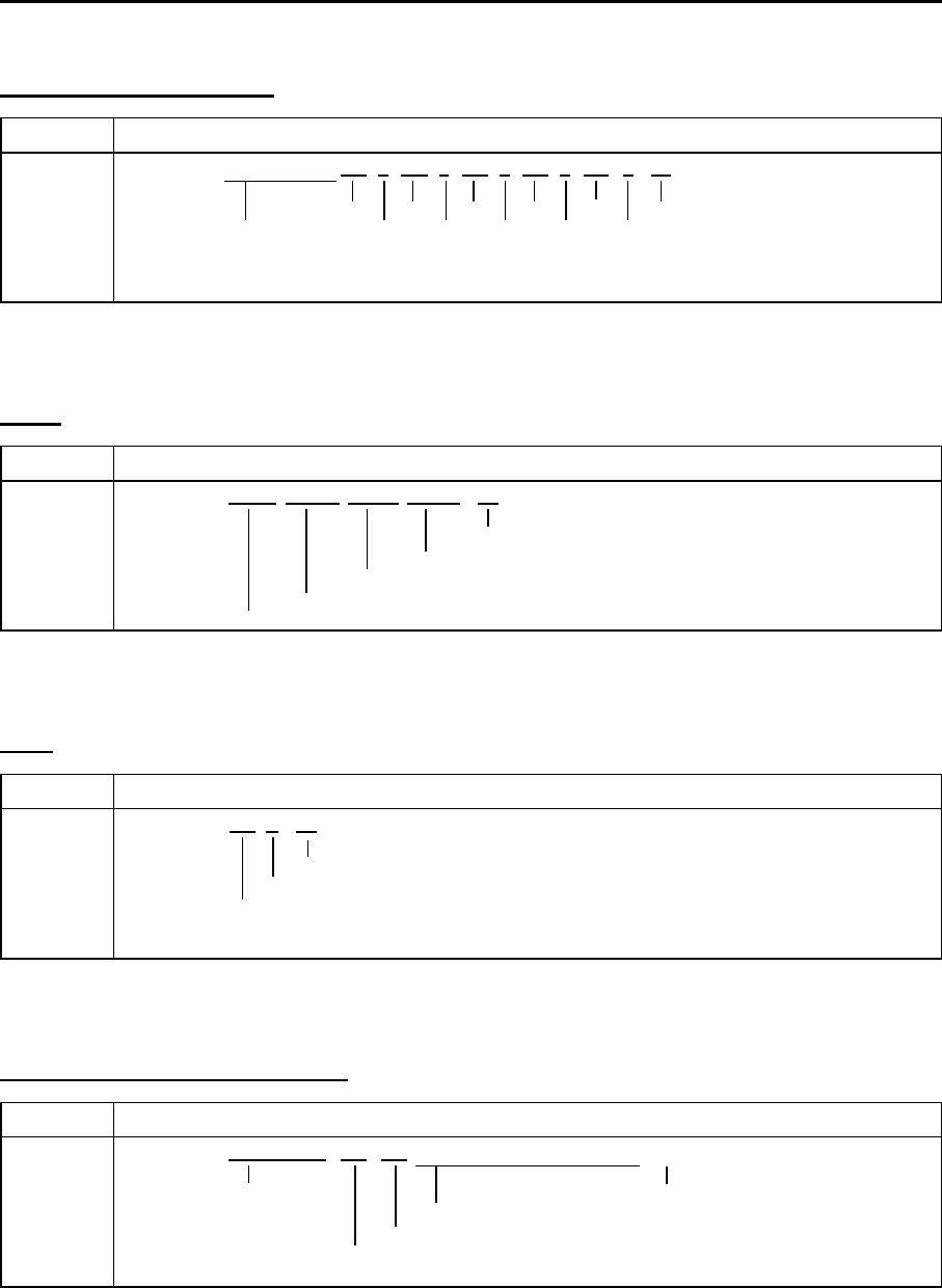
Chapter 11 Appendix MDC-7000P/7900P Series
0093169006-05E 11-20
Loran-C position (LOP)
GLC Geographic Position Loran-C
TD1 TD2 TD3 TD4 TD5 Check s u
m
Note*: Status
These fields are not used. status* status* status* status* status* A=Valid
B=Blink w arning
Note: When only tw o TD data are effective, TD data is displayed. C=Cycle w arning
S=SNR w arning
a*hh<CR><LF>x.x,a,x.x,a,x.x,a, x.x,a,x.x,a,$ -- GLC, xxxx, x.x,
Wind
MWD Wind direction and speed
*hh<CR><LF>
Chec k s u
m
Wind speed, m/s
Wind speed, knots
Wind direction, 0° to 359° magnetic
Wind direction, 0° to 359° true
$--
MWD ,
x.x, T,x.x, M,x.x, N, x.x, M,
ROT
ROT Rate of turn
*hh<CR><LF>
Chec k s u
m
Status, A=Valid V=Invalid
Rate of turn,
o
/min
"-" bow turns to port
$-- ROT, x.x,
A
,
GNSS satellite fault detection
GBS GNSS satellite fault detection
h *hh <CR><LF>
This field is not used. Check su
m
These fields are not used.
Expected error in longitude
Expected error in latitude
x.x, h,x.x,x.x,
xx,
x.x, x.x,$ -- GBS, hhmmss.ss,x.x,
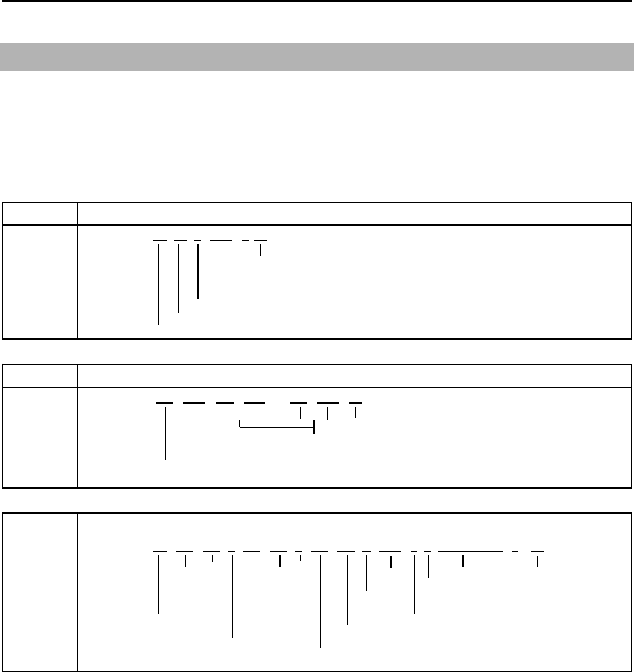
MDC-7000P/7900P Series Chapter 11 Appendix
0093169006-05E 11-21
11.3 Details of TT tracking data output
Data standard name: IEC61162-1 or IEC61162-2
Target data of the automatic tracking unit is provided via data connectors (NAV/EPFS/SDME) on
the back panel.
TTD Tracked target data
x*hh<CR><LF>
Chec k s u
m
Number of fill-bits, 0 to 5
Encapsulated tracked target data
Sequential message identifier, 0 to 9
Hex sentence number, 01 to F
F
Total hex number of sentences needed to transfer the message, 01 to FF
TLB Target label
*hh<CR><LF>
Chec k s u
m
Additional label pairs (x.x, c--c)
Label assigned to target 'n'
Target number 'n' reported by the device
TTM Tracked target message
*hh<CR><LF>
T
arget
T
arget
T
arget
UTC
Ch
ec
k
su
m
di
stance course,
l
a
b
e
l
R
e
f
erence
T
ype o
f
f
ro
m
d
egrees
S
pee
d/
target=
R
,acqu
i
s
i
t
i
on
ow n s
hi
p
t
rue
di
s
t
ance nu
ll
o
th
erw
i
se
A
=
A
u
t
oma
ti
c
T
arge
t
num
b
er,
T
arge
t
spee
d
un
it
s,
N
T
arge
t
s
t
a
t
us
M
=
M
anua
l
00
to
99
Ti
me to
CPA
L
=
L
ost
R
=
R
ecor
d
e
d
B
ear
i
ng
f
rom ow n s
hi
p,
(
m
i
n
)
Q
=
Q
uery
d
egrees true
Di
stance o
f
c
l
osest
T
=
T
rac
ki
ng
-po
i
nt-o
f
-approac
h
x.x,x.x,N,c--c,
a,a,
hhmmss.ss,
a,
$ RATTM, xx,x.x,x.x,T,x.x,x.x,T,
$
! RA TTD, hh,hh,x, s--s,
RATLB, x.x, c--c,x.x, c--c,…x.x,c--c
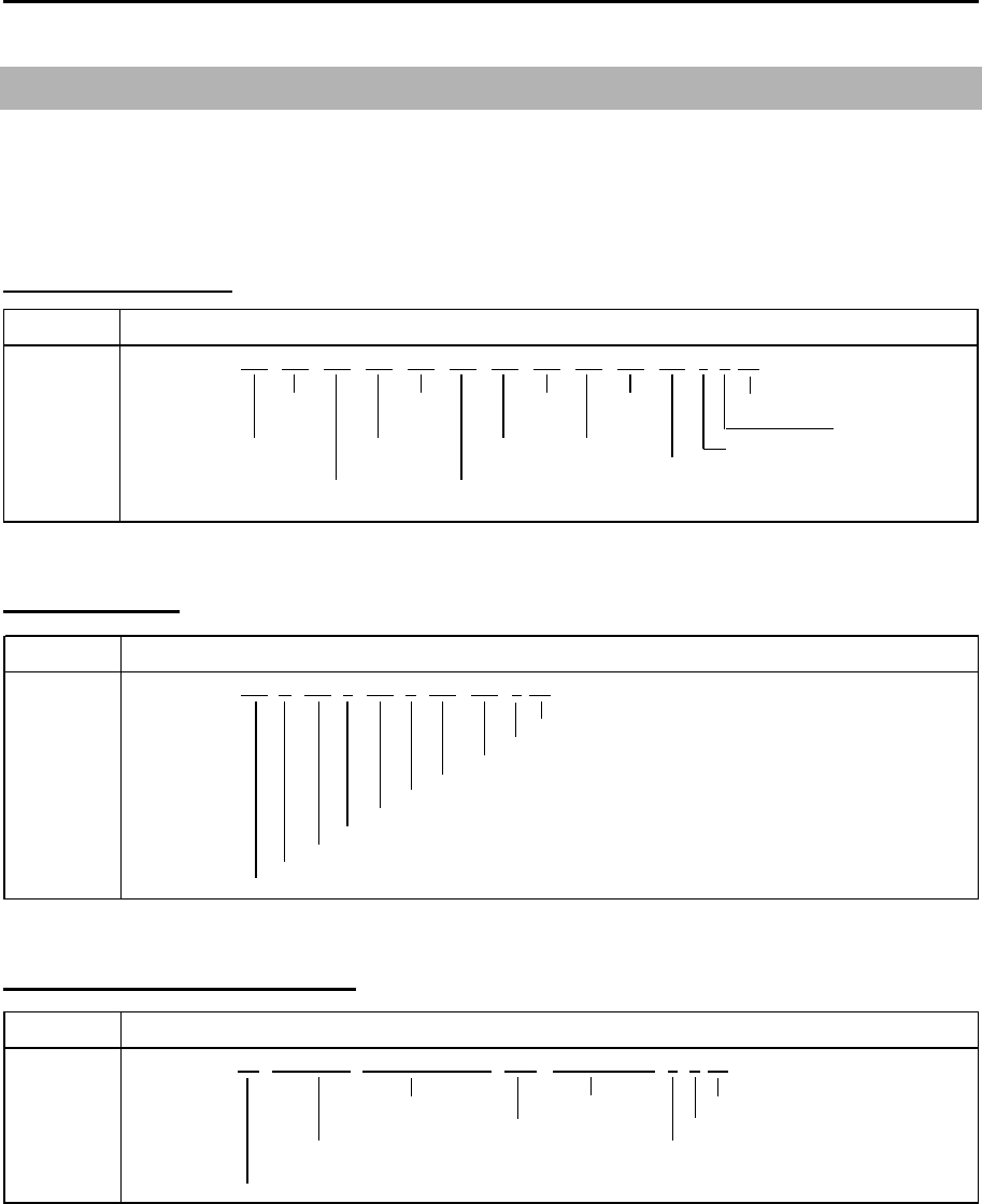
Chapter 11 Appendix MDC-7000P/7900P Series
0093169006-05E 11-22
RSD Radar system data
a*hh<CR><LF>
Origin1 Origin2 EBL2 Cursor Check su
m
Bearing Range Beraing Bearing Display mode
Origin 1 EBL1 VRM2 Cursor Range unit C=Course up
Range Bearing Bearing range Display K=km/h H=Head up
V RM1 Or igin2 Range N=NM N=Nor th up
Bearing Beraing S=SM/h
x.x,x.x,x.x,x.x,x.x,
a,
$ -- RSD, x.x,x.x,x.x,x.x,x.x,x.x,
11.4 Details of the radar data output
Data standard name: IEC61162-1 or IEC61162-2
Own ship data and radar system data are provided via data connectors (NAV/EPFS/SDME) on the
back panel.
Radar system data
Own ship data
OSD Own ship data
a*hh<CR><LF>
Ch
ec
k
su
m
S
pee
d
un
i
t,
K
=
k
m
/h
,
N
=
k
nots,
S
=statute m
il
es
/h
V
esse
l
d
r
if
t
(
spee
d)
V
esse
l
set,
d
egrees true
S
pee
d
re
f
erence,
B/M/W/R/P*
N
ote
*
R
e
f
erence
V
esse
l
spee
d
B
=
B
ottom trac
ki
ng
l
og
C
ourse re
ff
erence,
B/M/W/R/P*
M
=
M
anua
ll
y en
t
ere
d
V
esse
l
course,
d
egrees true
W
=
W
ater re
f
erence
d
H
ea
di
ng status,
A
=
d
ata va
lid
,
V
=
d
ata
i
n va
lid
R
=
R
a
d
ar trac
ki
ng
(
or
fi
xe
d
target
)
H
ea
di
ng,
d
egrees true
P
=
P
os
i
t
i
on
i
ng system groun
d
re
f
erence
$RAOSD, x.x,
A
,x.x,a,x.x,a,x.x,x.x,
Target latitude and longitude
TLL Target latitude and longitude
a*hh<CR><LF>
Target longitude UTC of data Check su
m
E/W Target label Reference target=R, null otherw ise
Target latitude Target status L=Lost
N/S Q=Quer y
Target number (00-99) T=Tracking
$ RATLL, xx, llll.ll, N/S, yyyyy.yy, E/W,c--c, hhmmss.ss,a,
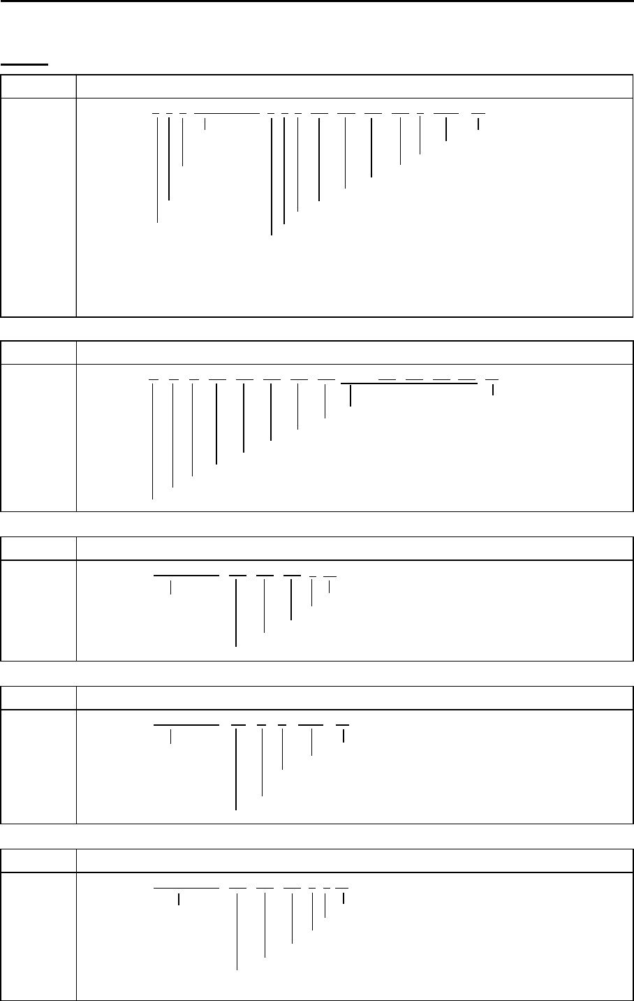
MDC-7000P/7900P Series Chapter 11 Appendix
0093169006-05E 11-23
ALF Alert sentence
Ti
me o
f
l
ast
Ch
ec
k
su
m
c
h
ange
Al
ert text
E
sca
l
at
i
on counter,
0
to
9
S
equent
i
a
l
R
ev
i
s
i
on counter,
1
to
99
message
Al
ert
i
nstance,
1
to
999999
id
ent
if i
er,
0
to
9
Al
ert
id
ent
if i
er
S
entence
M
anu
f
acturer mnemon
i
c co
d
e
num
b
er,
1
to
2
Al
ert state,
A
,
S
,
N
,
O
,
U
or
V**
T
ota
l
num
b
er o
f
ALF
sentences
Al
ert pr
i
or
i
ty,
E
,
A
,
W
or
C*
f
or t
hi
s message,
1
to
2
Al
ert category,
A
,
B
or
C
N
ote
**
Al
ert state
V
=
A
ct
i
ve-
U
nac
k
now
l
e
d
ge
N
ote
*
Al
ert pr
i
or
i
ty
S
=
A
ct
i
ve-
Sil
ence
d
E
=
E
mergency
Al
erm
(f
or use w
i
t
h
B
r
id
ge
Al
ert
M
anagement
)
A
=
A
ct
i
ve-
A
c
k
now
l
e
d
ge or act
i
ve
A
=
Al
arm
O
=
A
ct
i
ve-
R
espons
ibili
ty trans
f
erre
d
W
:
W
arn
i
ng
U
=
R
ect
if i
e
d
-
U
nac
k
now
l
e
d
ge
C
=
C
aut
i
on
N
=
N
orma
l
$ -- ALF, x,x,x, hhmmss.ss,a,a,a,
aaa,
x.x,x.x,x.x,x, c---c *hh<CR><LF>
Alarm
ALC Cyclic alert list
ALC,
Ch
ec
k
su
m
Addi
t
i
ona
l
Al
ert entr
i
es
R
ev
i
s
i
on counter
Al
ert entry
1
Al
ert
i
nstance
Al
ert
id
ent
if i
er
M
anu
f
acturer mnemon
i
c co
d
e
N
um
b
er o
f
a
l
ert entr
i
es
S
equen
ti
a
l
message
id
en
tifi
er,
00
t
o
99
S
entence num
b
er,
01
to
99
T
ota
l
num
b
er o
f
sentences
f
or t
hi
s message,
01
to
99
ARC Alert command refused
c*hh<CR><LF>
Reles e time Chec k s u
m
Note*
Refused alert command, A, Q, O or S*
A: Acknowledge
Alert instance, 1 to 999999
Q: Req uest / repeat infor mation
Alert identifier
O: Responsibili ty transfer
Manuf acturer mnemonic code
S: Silence
ALR Set alarm state
Time of alarm Check su
m
condition Alarm's description text
change, UTC Alarm's acknow ledge state, A=acknow ledged
V=unacknow ledged
Alarm condition (A=threshold exceeded, V=not exceeded)
Unique alarm number (identifier) at alarm source
ACN Alert command
a*hh<CR><LF>
Reles e time Chec k s u
m
Sentence status flag: "C"
Alert command, A, Q, O or S* Note* Alert command
Alert instance, 1 to 999999 A: Acknow ledge
Alert identifier Q: Request / repeat information
manufacture mnemonic code O: Responsibility transfer
S: Silence
*hh<CR><LF>A,A, c---c$ -- ALR, hhmmss.ss,
xxx,
x.x,x.x,c,$ -- ACN, hhmmss.ss,
aaa,
x.x,……,
aaa,
x.x,x.x,x.x*hh<CR><LF>
$ -- ARC, hhmmss.ss,
aaa,
x.x,x.x,
$ --
xx,xx,xx,
x.x,
aaa,
x.x,x.x,
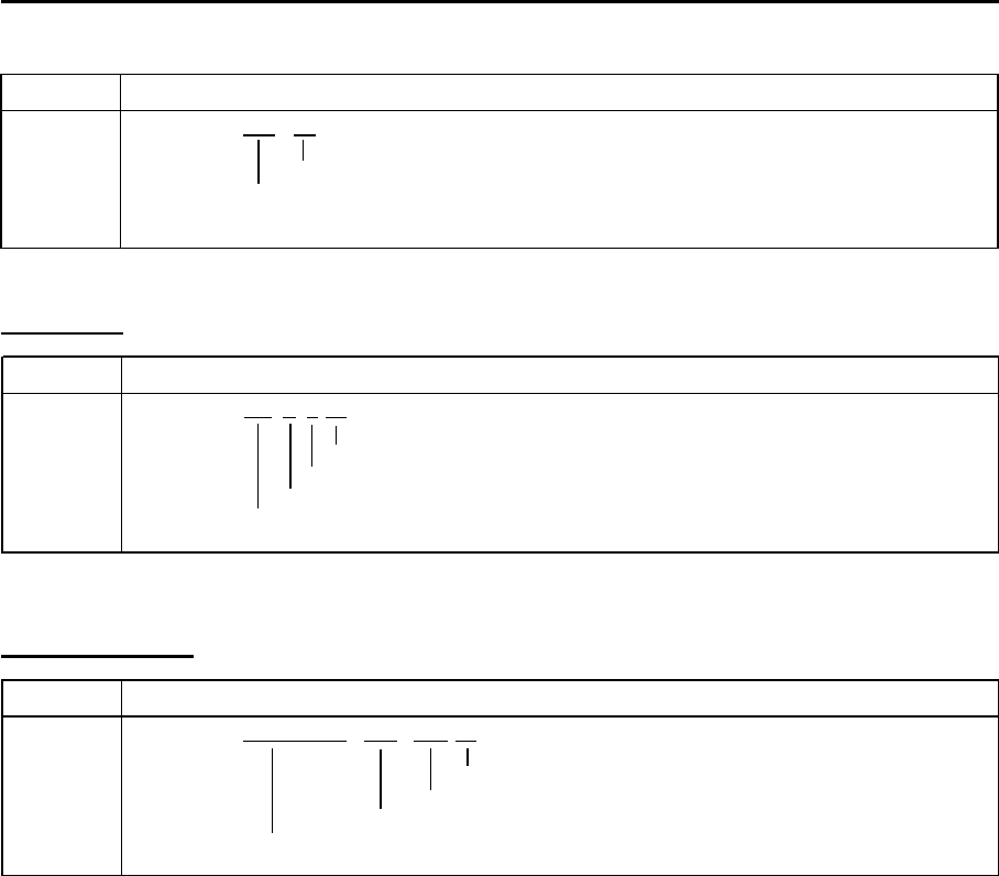
Chapter 11 Appendix MDC-7000P/7900P Series
0093169006-05E 11-24
Heartbeat
HBT Heartbeat supervision sentence
x*hh<CR><LF>
Chec k s u
m
Sequential sentence identifier
Equipment status A=Yes, V=No
Configured repeat interval
$-- HBT, x.x,
A
,
Event message
EVE General event message
c--c*hh<CR><LF>
Chec k s u
m
Event description
Tag code used for identification of source of event
Ev e n t t ime
$ -- EVE, hhmmss.ss, c--c,
ACK Acknowledge alarm
Chec k s u
m
Unique alarm number (identifier) at alarm source
$ -- ACK, xxx *hh<CR><LF>
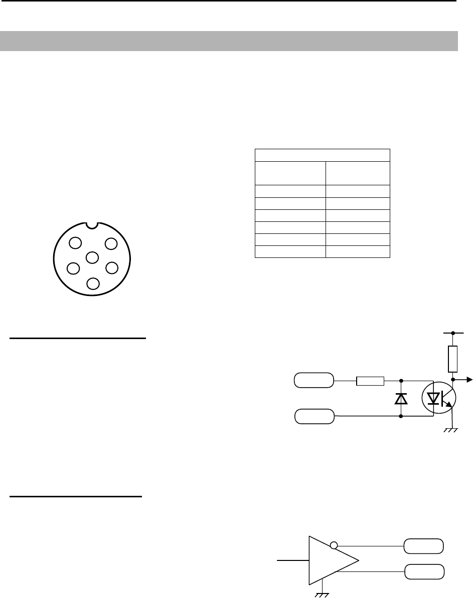
MDC-7000P/7900P Series Chapter 11 Appendix
0093169006-05E 11-25
11.5 Interface specification
11.5.1 NAV and EPFS serial data input/output specification
Serial data input (Listener):
Standard-type signal conforming to IEC61162-1 or
IEC 61162-2 is acceptable.
Input load: 500 Ohm
Circuit configuration: Photo coupler
Type ACPL-M61 (Avago)
Serial data output (Talker):
Standard-type signal conforming to IEC61162-1 or
IEC 61162-2 is transmittable.
Circuit configuration: RS422 driver IC
Type SN65HVD3085 (TI)
Serial data output circuit
OUT-B
Data output
OUT-A
SN65HVD3085
J3 and J5
Data connector pin assignment
(Display unit upper view)
J3 and J5
Pin number Signal
name
1 Shield
2 OUT-A
3 OUT-B
4 IN-A
5 IN-B
6 +12V
Data connector pin assignment
1
2
3
4
5
6
Input connector: J3 and J5
Connector used: BD-06PMMP-LC7001
Connector acceptable: BD-06BFFA-LL6001
Serial data input circuit
IN-A
IN-B
500
Input data A
Input data B
+Vcc
A
CPL-M61
Note: +12V of pin no.6 is used for power supply o
f
Junction box JB-35 or other device
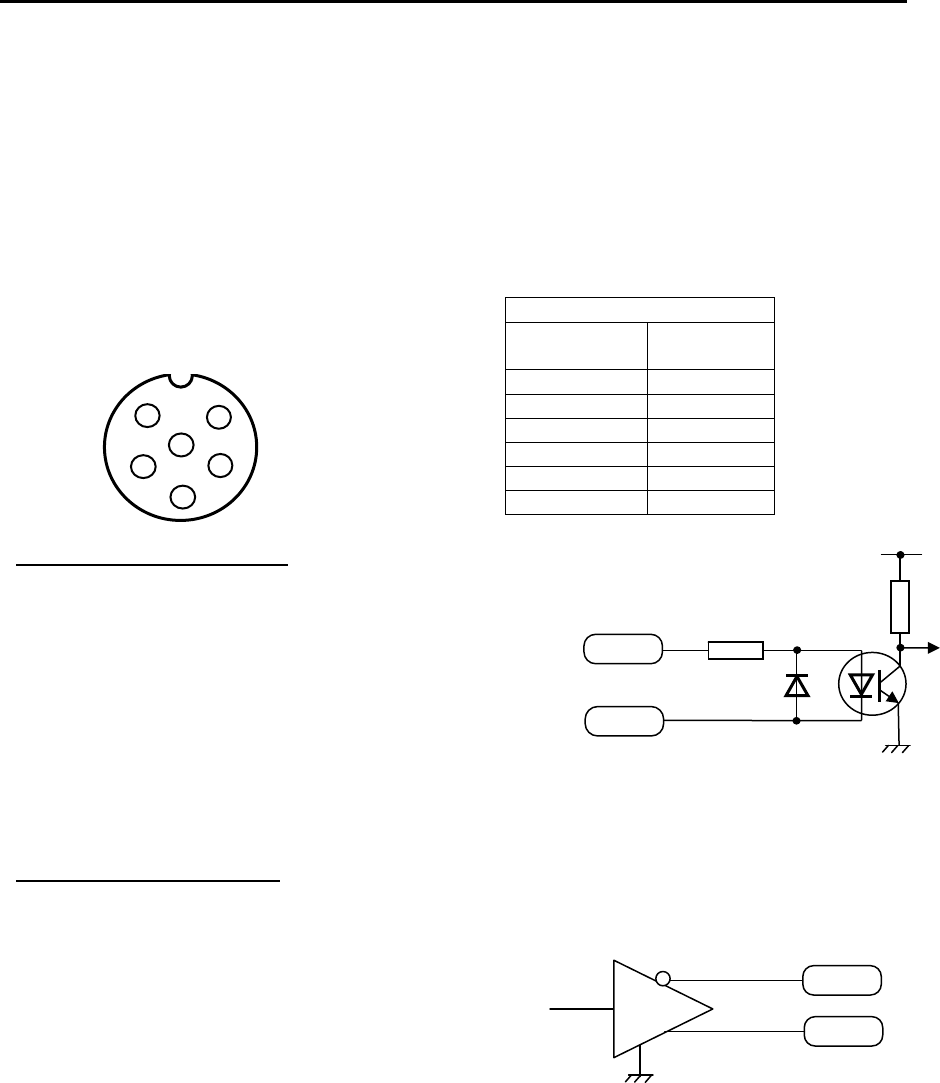
Chapter 11 Appendix MDC-7000P/7900P Series
0093169006-05E 11-26
11.5.2 SDME serial data input/output specification
Serial data input (Listener):
Standard-type signal conforming to IEC61162-1 or
IEC 61162-2 is acceptable.
Input load: 500 Ohm
Circuit configuration: Photo coupler
Type ACPL-M61 (Avago)
Serial data output (Talker):
Standard-type signal conforming to IEC61162-1 or
IEC 61162-2 is transmittable.
Circuit configuration: RS422 driver IC
Type SN65HVD3085 (TI)
Serial data output circuit
OUT-B
Data output
OUT-A
SN65HVD3085
J6
Data connector pin assignment
(Display unit upper view)
J6
Pin number Signal
name
1 Shield
2 OUT-A
3 OUT-B
4 IN-A
5 IN-B
6 NC
Data connector pin assignment
1
2
3
4
5
6
Input connector: J6
Connector used: BD-06PMMP-LC7001
Connector acceptable: BD-06BFFA-LL6001
Serial data input circuit
IN-A
IN-B
500
Input data A
Input data B
+Vcc
A
CPL-M61
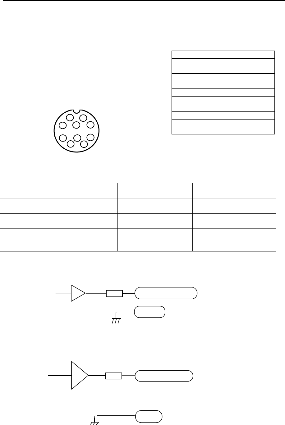
MDC-7000P/7900P Series Chapter 11 Appendix
0093169006-05E 11-27
11.5.3 VDR (external monitor) and Alarm output signal specification
Output connector name: VDR & Alarm
Connector used: BU-10PMMP-LC7001
Connector acceptable: BU-10BFFA-LL7001
Pin location is shown below.
Signal specification
This RGB output is compliant with the image test defined in the VDR test standard IEC61996.
VDR output cannot be deactivated by the user.
Signal name Frequency Polarity Signal
width Level Impedance
Horizontal sync signal
(H-SYNC) 63.981 kHz Negative 1.037 μs TTL 200 Ω
Vertical sync signal
(V-SYNC) 60.0 Hz Negative 47 μs TTL 200 Ω
R, G, B Video signal - Positive -
0.7 V p-p 75 Ω
Alarm output - - Contact* - Capacity 1A
* Alarm contact will open in case of failure.
Pin number Signal name
1 RVD
2 R-GND
3 GVD
4 G-GND
5 BVD
6 B-GND
7 H-SYNC
8 V-SYNC
9 ALARM
10 ALARM
J1
External monitor and alarm output connector pin
assignment
(Display unit upper view)
RVD/GVD/BVD
GND
R, G, B Video signal
Ground
Circuit for horizontal sync, vertical sync signal output
75
GND
TC74VHC08
Horizontal sync,
vertical sync signal
Ground
H-SYNC/V-SYNC
75
LMH6683
1
2
3 4 5 6
7
8
9
10
External monitor and alarm output
connector pin assignment
Circuit for R, G, B video signal output
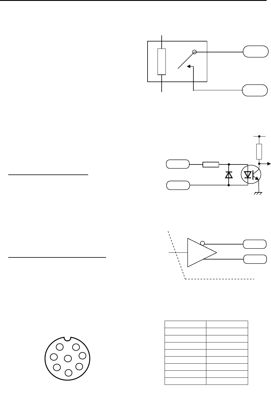
Chapter 11 Appendix MDC-7000P/7900P Series
0093169006-05E 11-28
Alarm contact specification
Max. switching voltage 30 V
Max. current capacity 1 A
(Resistive load)
Note: Alarm contact will open in case of failure.
11.5.4 Serial data input/output specification (AIS)
Pin number Signal name
1 Shield
2 IN-A
3 IN-B
4 OUT-B
5 OUT-A
6 GND
7 NC
8 NC
Data connector pin assignment
I/O connector AIS (J2)
Connector used: BD-08PMMP-LC7001
Connector acceptable: BD-08BFFA-LL6001
Serial data input (Listener):
Standard signals conforming to IEC61162-2 is
acceptable.
Input load 500 Ohm
Circuit configuration: Photo coupler
Type ACPL-M61 (Avago)
Serial data output circuit (Talker):
Standard signals conforming to IEC61162-2 can be
output.
Circuit configuration: RS422 Driver/Receiver IC
Type SN65HVD3085 (TI)
Separated from ground level
1
2
3 4
7
8
5
6
J2
Data connector pin assignment
(Display unit upper view)
Note: Pin 7 and pin 8 are used for error detection input signal for AIS system.
It denotes [Short: Normal, Open: Error]. Please short #7 and #8 pin at AIS normal state.
OUT-A
Data output
OUT-B
SN65HVD3085
Serial data output circuit
alarm
alarm
HY1Z-5V
For external device
IN-A
IN-B
500
Data input A
+Vcc
A
CPL-M61
Data input B
Serial data input circuit
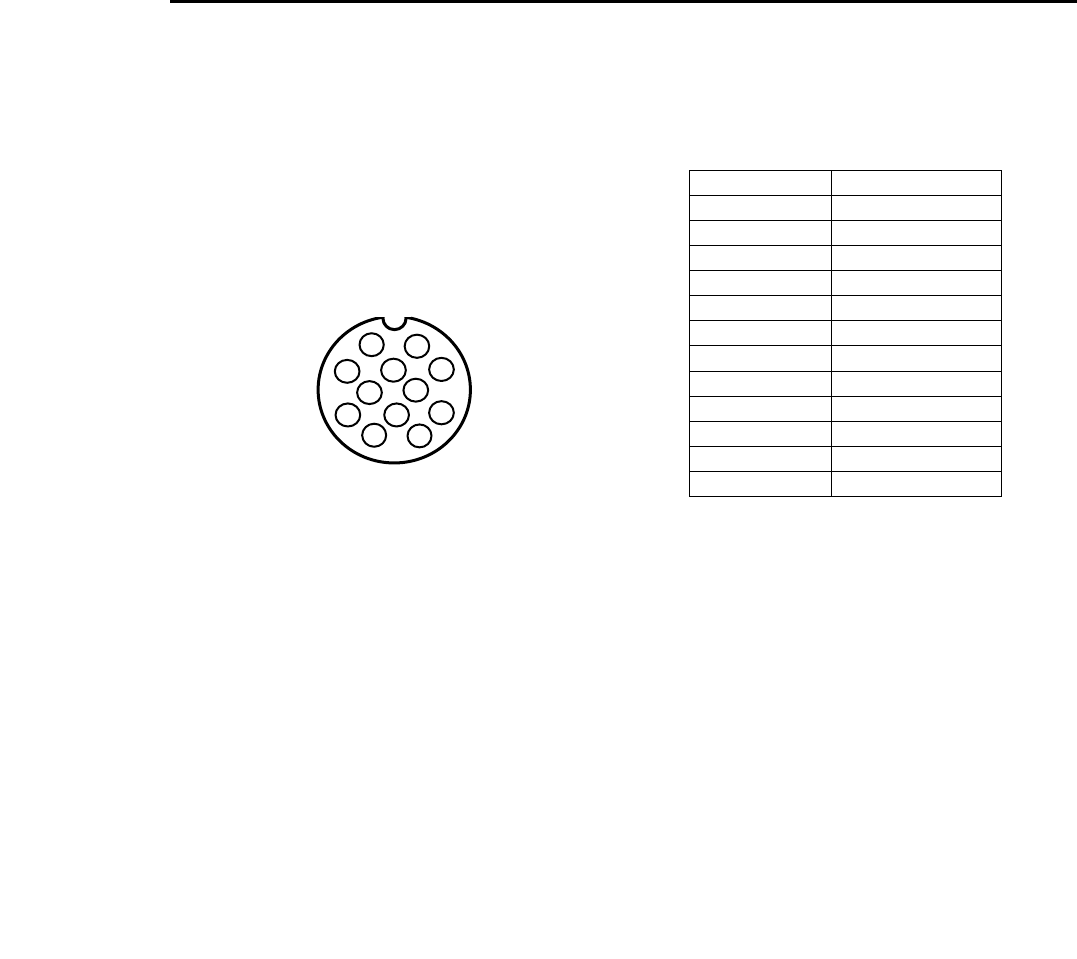
MDC-7000P/7900P Series Chapter 11 Appendix
0093169006-05E 11-29
11.5.5 Radar input/output signal specification
I/O connector: Inter-switch (J8)
Connector used: BU-12PMMP-LC7001
Connector acceptable: BU-12BFFA-LL7001
Pin number Signal name
1 VIDEO OUT
2 TRIG OUT
3 GND
4 AZIP OUT
5 SHF OUT
6 GND
7 VIDEO IN
8 TRIG IN
9 GND
10 AZIP IN
11 SHF IN
12 +12VDC
Data connector pin assignment
1
2
3 4 5
6
7
8
9 12
10
11
J8
Inter-switch connector pin assignment
(Display unit upper view)

Chapter 11 Appendix MDC-7000P/7900P Series
0093169006-05E 11-30
11.5.6 Talker device code of the data output devices
The device code displayed as talker is shown in the table below.
Data output device Talker device code Displayed code
Galileo positioning system GA GAL
Global positioning system (GPS) GP GPS (See below)
Global positioning system (DGPS) GP DGPS (See below)
GLONASS positioning system GL GLONASS
Global navigation satellite system GN GNSS
Heading sensors: compass, magnetic HC HC
: gyro, north seeking HE GYRO
: gyro, non-north seeking HN GYRO
Integrated instrumentation I I INS
Integrated navigation IN INS
Loran-C LC LC
Electronic positioning system SN EPFS
Velocity sensors: Doppler, general VD DLOG
: magnetic log VM LOG
: mechanical log VW LOG
Other devices Display of talker device
11.5.7 Priority of talker device code
Heading
II > IN> HE >HN > HC > GN > GP > GL > GA >SN
Speed
II > IN > VD > GN > GP > GL > GA > SN > VM > VW
Position
II > IN > GN > GP > GL > GA > SN >LC
GNS
GN > GP > GL > GA
Notice
The change between GPS and DGPS of the device name displayed is based on the operational
status display in the GLL and GGA sentences. Refer to 11.2.2 Details of the data input format.

MDC-7000P/7900P Series Chapter 12 Index
0093169006-05E 12-1
Chapter 12 Index
A
ACTIVE/SLEEP ................................................. 4-10
AIS ....................................................................... 4-9
AIS auto ACQ..................................................... 4-13
AIS FILTER ........................................................ 4-12
AIS ID DISP ......................................................... 4-4
AIS target symbol ............................................... 4-14
Alarm ................................................................... 3-1
Alarm display ....................................................... 1-6
Alarm History list ................................................ 3-13
Alarm list ................................................... 3-12, 9-10
Antenna position mark ....................................... 2-49
AREA ................................................................. 6-11
ASSOCIATION ..................................................... 4-6
AUTO ACQ AREA ................................................ 4-7
AUTO GAIN ......................................................... 2-6
AUTO SEA ........................................................... 2-8
Automatic acquisition area ................................... 4-7
B
BACKUP .............................................................. 7-5
Barge icon ............................................................ 5-3
Bearing mode..................................................... 2-25
Brightness .......................................................... 2-30
Brilliance .............................................................. 2-2
C
C UP .................................................................. 2-15
CAUTION ............................................................. 1-7
CCRP ................................................................. 2-48
CFAR ................................................................. 2-11
COAST LINE ........................................................ 6-3
Course up .......................................................... 2-15
CPA/TCPA ........................................................... 4-3
CROSS .............................................................. 2-45
Cursor ....................................................... 2-22, 2-46
Cursor Access .................................................... 1-11
Cursor data ........................................................ 2-46
D
DATUM .............................................................. 6-13
Day/Night ........................................................... 2-30
Delete all TT target ............................................ 4-19
Delete TT target ................................................. 4-19
Display center .................................................... 2-48
Display Mode ..................................................... 2-14
DUAL MASTER ................................................. 2-45
DUAL SLAVE ..................................................... 2-45
E
EBL .................................................................... 2-23
EBL OFFSET ..................................................... 2-24
Echo alarm ........................................................... 3-1
Echo color .......................................................... 2-30
Echo color rejection ........................................... 2-40
Electronic bearing lines ...................................... 2-23
ERBL ................................................................. 2-28
EVENT MKR ...................................................... 6-10
Expansion .......................................................... 2-38
External buzzer .................................................... 7-3
External save ....................................................... 7-6
F
Fault diagnosis ..................................................... 9-1
FERRY MODE ................................................... 2-51
Function key ...................................................... 2-35
G
GAIN .................................................................... 2-6
GPS BUOY ........................................................ 6-15
Ground stabilization ........................................... 2-20

Chapter 12 Index MDC-7000P/7900P Series
0093169006-05E 12-2
Guard line ............................................................ 5-1
Guard zone alarm ............................................... 3-7
H
H UP ..................................................................2-14
Head up..............................................................2-14
Heading line .......................................................2-31
HELP window ...................................................... 7-4
HISTORY LIST ...................................................3-13
HL blink ............................................................... 5-2
How to update ..................................................... 7-8
I
ID DISP SIZE ...................................................... 4-5
INDEPENDENT MASTER ..................................2-44
INDEPENDENT SLAVE .....................................2-44
Input range .......................................................... 4-5
Internal save ........................................................ 7-5
Inter-switch .........................................................2-44
IR .......................................................................2-39
L
LIST ...................................................................3-12
LOST ALARM ...................................................... 4-3
M
MAINTENANCE .......................................... 1-11, 7-5
MAINTENANCE menu ....................................... 1-11
MAN GAIN .......................................................... 2-6
MAN SEA ............................................................ 2-8
Manual acquisition .............................................4-18
MAP .................................................................... 6-1
Map area ............................................................. 3-3
MENU ................................................................1-10
MMSI .................................................................. 4-11
MON ...................................................................2-47
MONITOR ..........................................................2-45
MONITORED ROUTE ........................................6-12
N
N UP .................................................................. 2-16
NAV LINE ............................................................. 6-8
Nav line cross ...................................................... 3-8
Noise rejection ................................................... 2-40
North up ............................................................. 2-16
O
Off Center .......................................................... 2-34
Off-centering ...................................................... 2-34
Own ship outline ................................................ 2-50
OWN SHIP PAST TRACK .................................... 6-1
Own ship profile ................................................. 2-50
P
Panel brilliance ..................................................... 2-2
Parallel Index (PI) lines ...................................... 2-26
Parameter reset ................................................... 7-6
PASSWORD ...................................................... 1-11
Past position ........................................................ 4-8
PAST POSN ......................................................... 4-8
PATH PREDICTOR .............................................. 4-2
Performance monitor .......................................... 2-47
PI ....................................................................... 2-26
Picture mode ...................................................... 2-36
POWER ON/OFF ................................................. 2-1
Priority ................................................................ 3-12
Process .............................................................. 2-37
Pulse width ............................................... 2-13, 2-41
Pulse width (SP/LP) ........................................... 2-13
R
Radar Beacons .................................................. 2-42
Radar Display ...................................................... 1-1
Radar Enhancer ................................................. 2-42
RAIN .................................................................. 2-10
RAIN MAN ......................................................... 2-12
Rain/snow clutter................................................ 2-10

MDC-7000P/7900P Series Chapter 12 Index
0093169006-05E 12-3
Range .................................................................. 2-5
Range Rings ...................................................... 2-21
Range scale ......................................................... 2-5
Range unit ........................................................... 2-5
Reference position ............................................. 2-48
Reference target ................................................ 4-20
Relative display .................................................. 2-33
Relative motion .................................................. 2-17
Reset ................................................................... 7-6
Reset true motion ............................................... 2-18
ROUTE ................................................................ 6-9
RR ...................................................................... 2-21
S
SART ................................................................. 2-42
SEA ...................................................................... 2-8
Sea clutter ............................................................ 2-8
Sea stabilization ................................................. 2-19
Ship outline ........................................................ 2-50
Sleeping lost ...................................................... 4-13
STAB INDICATOR ............................................... 4-2
STAB MODE ...................................................... 2-19
STANDBY ............................................................ 2-1
Stern line .............................................................. 5-2
T
Target trail .......................................................... 2-31
TEST TGT .......................................................... 4-23
TIME INCREMENT ..................................... 2-29, 4-1
TM reset ............................................................. 2-18
TOTAL HOUR ...................................................... 7-7
Tracked target symbol ....................................... 4-22
Trail .................................................................... 2-31
Transmission ........................................................ 2-3
Trial manoeuvre ................................................. 4-34
True display ....................................................... 2-33
True motion ........................................................ 2-17
TT ...................................................................... 4-17
TT ID DISP .......................................................... 4-4
Tuning method ..................................................... 2-4
Turn indicator ..................................................... 4-11
TX HOUR ............................................................. 7-7
U
User memory ....................................................... 7-2
UTC / LOCAL time ............................................... 7-1
V
Variable Range Marker ...................................... 2-22
VECTOR .............................................................. 4-1
VECTOR REL/TRUE ........................................... 4-1
Video contrast .................................................... 2-39
VRM ................................................................... 2-22
W
WAIT .................................................................... 2-1
WARNING............................................................ 1-7