Kohler KOHLER006 NUMI Integrated Toilet User Manual No Job Name
Kohler Co. NUMI Integrated Toilet No Job Name
Kohler >
Contents
- 1. Manual 1
- 2. Manual 2
Manual 2

JOBNAME: No Job Name PAGE: 1 SESS: 17 OUTPUT: Wed Jun 23 13:46:00 2010
Installation Guide
Toilet
Mproduct numbers are for Mexico (i.e. K-12345M)
Los números de productos seguidos de Mcorresponden a México
(Ej. K-12345M)
Français, page “Français-1”
Español, página “Español-1”
K-3900
1132336-2-A
This is the latest version of the Installation Guide.
The through-the-floor information is accurate and complete, however,
we understand it unnecessary for the Chinese market.
Please modify as necessary to the meet your market.
We can supply you with the original art files if changes are needed.
JOBNAME: No Job Name PAGE: 2 SESS: 17 OUTPUT: Wed Jun 23 13:46:00 2010
Important Information
NOTE: This product is designed for installation with the electrical and water supplies located through
either the wall or the floor.
Grounding Instructions
•This product should be grounded. In the event of an electrical short circuit, grounding reduces the
risk of electric shock by providing an escape wire for the electric current. This product is equipped
with a cord having a grounding wire with a grounding plug. The plug must be plugged into an
outlet that is properly installed and grounded.
DANGER: Risk of electric shock. Improper use of the grounding plug can result in a risk of
electric shock.
•If repair or replacement of the cord or plug is necessary, do not connect the grounding wire to either
flat blade terminal. The wire with insulation having an outer surface that is green with or without
yellow stripes is the grounding wire.
•Check with a qualified electrician or service personnel if the grounding instructions are not
completely understood, or if in doubt as to whether the product is properly grounded.
•This product is factory equipped with a specific electric cord and plug to permit connection to a
proper electric circuit. Make sure that the product is connected to an outlet having the same
configuration as the plug. No adapter should be used with this product. Do not modify the plug
provided — if it will not fit the outlet, have the proper outlet installed by a qualified electrician. If
the product must be reconnected for use on a different type of electric circuit, the reconnection
should be made by qualified service personnel.
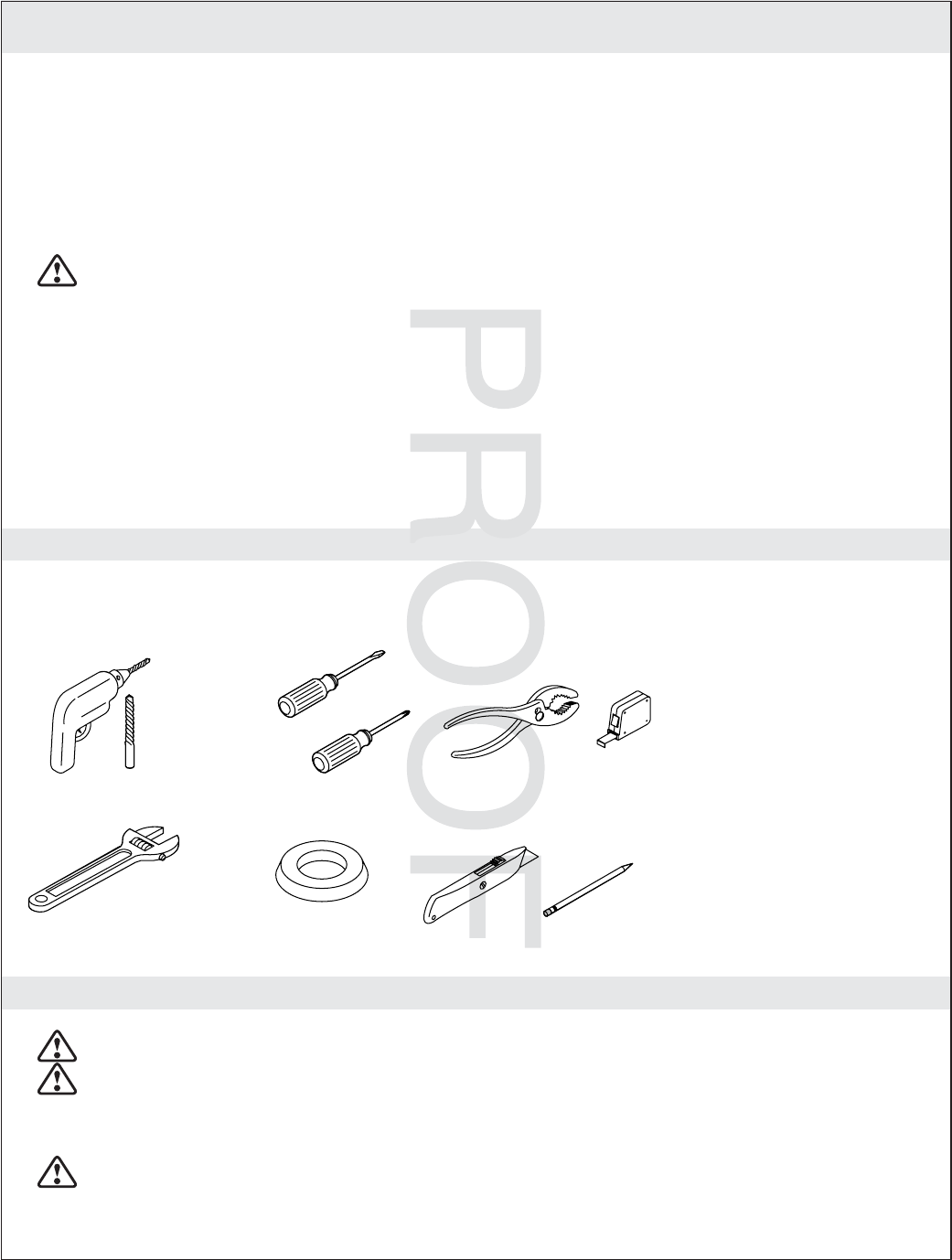
Tools and Materials
Before You Begin
DANGER: Risk of electric shock. Disconnect power before servicing.
DANGER: Risk of electric shock. For plug-in installations/wall-mounted electrical supply:
Connect only to a properly-grounded, grounding-type receptacle which is protected by a 120 V, 15
A, 60 Hz Ground-Fault Circuit-Interrupter (GFCI) or Residual Current Device (RCD). Do not
remove the grounding pin or use a grounding adapter.
CAUTION: Risk of personal injury. This toilet weighs approximately 100 lbs (45 kg). Lift the toilet
with two people, employing proper lifting technique.
Drill with assorted Bits Screwdrivers
Wax Ring
Adjustable Wrench
Plus:
• Rug or Protective Material
• Tape
1132336-2-A 2 Kohler Co.
Confirm electrical needs, change as
required.

JOBNAME: No Job Name PAGE: 3 SESS: 17 OUTPUT: Wed Jun 23 13:46:00 2010
Before You Begin (cont.)
CAUTION: Risk of hazardous gases. If a new toilet is not installed immediately, temporarily place
a rag in the floor flange opening.
NOTICE: Follow all local plumbing and electrical codes.
IMPORTANT! For ease of installation, install the docking station power cord before the sub wall and
finished wall are installed.
Observe all local plumbing and building codes.
Carefully inspect the new toilet for damage.
Consult the online users guide at kohler.com for more information.
Kohler Co. reserves the right to make revisions in the design of products without notice, as specified
in the Price Book.
Kohler Co. 3 1132336-2-A
JOBNAME: No Job Name PAGE: 4 SESS: 17 OUTPUT: Wed Jun 23 13:46:00 2010
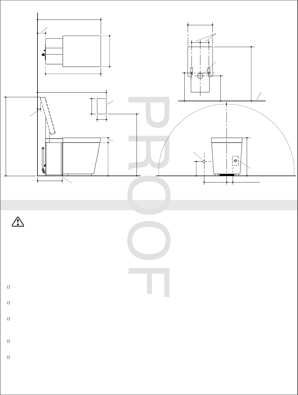
Rough-in - Wall Mount Electrical and Water Supply
DANGER: Risk of electric shock. Disconnect power before servicing.
NOTICE: The locations for the supply shut-off, electrical outlet, and docking station cord are suggested
locations. Make sure all installations adhere to applicable codes and standards.
IMPORTANT! If the supply shut-off is installed directly behind the toilet, the back panel cannot be
removed for servicing. Removing the back panel would then require the entire toilet be removed.
IMPORTANT! Do not install any items behind the toilet that will interfere with the seat when it is raised.
All decorative items should be at least 37″high to allow clearance for the seat.
The remote docking station is equipped with a 15’ (4.5 M) power cord. The station mounting
location shown for the docking station is ADA compliant.
The supplied power cord is 56″(142.2 cm) in length. The cord should be installed before the
finished wall are installed if possible.
The toilet is equipped with a motion sensor to automatically open the seat when movement is
sensed. This sensor has a maximum range of 51-1/2″(130 cm). Sensitivity can be adjusted using the
User Interface.
The toilet is equipped with a motion sensor seat actuator, located on the right side of the toilet. This
sensor has a maximum range of 8″(20.3 cm). Keep this area free of obstructions.
Supply stop inlet should be 1/2″NPT. Supply stop outlet needs to be 1/2″NPSM.
Front of Bowl
25-3/4" (65.4 cm)
2-5/8"
(6.7 cm) D.
14-1/2"
(36.8 cm)
25-1/4"
(64.1 cm)
13-5/8"
(34.6 cm)
10-13/16" (27.5 cm)
Finished Wall
3-3/4" (9.5 cm)
29-1/2" (74.9 cm)
12"
(30.5 cm)
12" (30.5 cm)
15-5/8"
(39.7 cm)
2-1/4"
(5.7 cm)
1-3/4"
(4.4 cm)
36-1/4"
(92.1 cm)
Power Cord
Reaches
56" (142.2 cm)
C
L Of Outlet
4-1/16"
(10.4 cm)
5-15/16"
(15.1 cm)
41" (104.1 cm) -
66" (167.6 cm)
38" (96.5 cm) - 66" (167.6 cm)
4-3/4" (12.1 cm)
Remote Dock
2" (5.1 cm)
17-7/8"
(45.4 cm)
6"
(15.2 cm)
8" (20.3 cm)
Outlet
1/2" NPS
Supply
1132336-2-A 4 Kohler Co.
Confirm location of electrical and
water supplies, adjust as
needed.
JOBNAME: No Job Name PAGE: 5 SESS: 17 OUTPUT: Wed Jun 23 13:46:00 2010
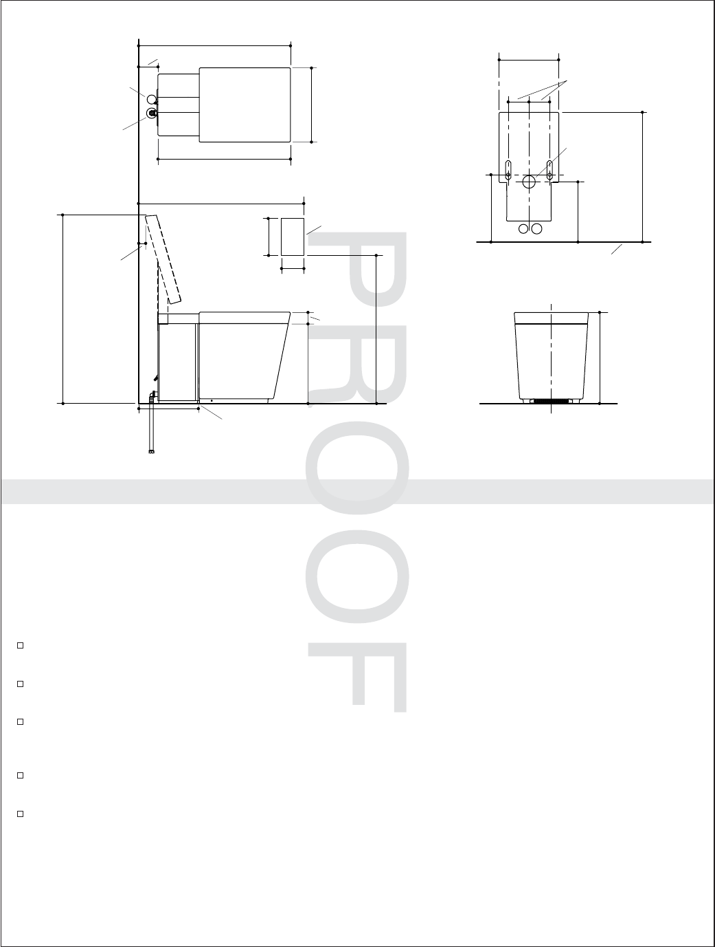
Roughing-in - Through-The-Floor Water and Electrical
NOTICE: The locations for the supply shut-off, electrical outlet, and docking station cord are suggested
locations. Make sure all installations adhere to applicable codes and standards.
IMPORTANT! If the supply shut-off is installed directly behind the toilet, the back panel cannot be
removed for servicing. Removing the back panel would then require the entire toilet be removed.
IMPORTANT! Do not install any items behind the toilet that will interfere with the seat when it is raised.
All decorative items should be at least 37″high to allow clearance for the seat.
The remote docking station is equipped with a 15’ (4.5 M) power cord. The station mounting
location shown for the docking station is ADA compliant.
The supplied power cord is 56″(142.2 cm) in length. The cord should be installed before the
finished wall are installed if possible.
The toilet is equipped with a motion sensor to automatically open the seat when movement is
sensed. This sensor has a maximum range of 51-1/2″(130 cm). Sensitivity can be adjusted using the
User Interface.
The toilet is equipped with a motion sensor seat actuator, located on the right side of the toilet. This
sensor has a maximum range of 8″(20.3 cm). Keep this area free of obstructions.
Supply stop inlet should be 1/2″NPT. Supply stop outlet needs to be 1/2″NPSM.
Front of Bowl
25-3/4" (65.4 cm)
2-5/8"
(6.7 cm) D.
14-1/2"
(36.8 cm)
25-1/4"
(64.1 cm)
13-5/8"
(34.6 cm)
10-13/16" (27.5 cm)
Finished Wall
3-3/4" (9.5 cm)
29-1/2" (74.9 cm)
12"
(30.5 cm)
12"
(30.5 cm)
15-5/8"
(39.7 cm)
2-1/4"
(5.7 cm) 17-7/8"
(45.4 cm)
1-3/4"
(4.4 cm)
36-1/4"
(92.1 cm)
4-1/16"
(10.4 cm)
5-15/16"
(15.1 cm)
41" (104.1 cm) -
66" (167.6 cm)
38" (96.5 cm) - 66" (167.6 cm)
4-3/4" (12.1 cm)
Remote Dock
C
L Of Outlet
1-1/2" (3.8 cm) D.
Water Supply Hole
1-1/4" (3.2 cm) D.
Power Supply Hole
Kohler Co. 5 1132336-2-A
JOBNAME: No Job Name PAGE: 6 SESS: 17 OUTPUT: Wed Jun 23 13:46:00 2010
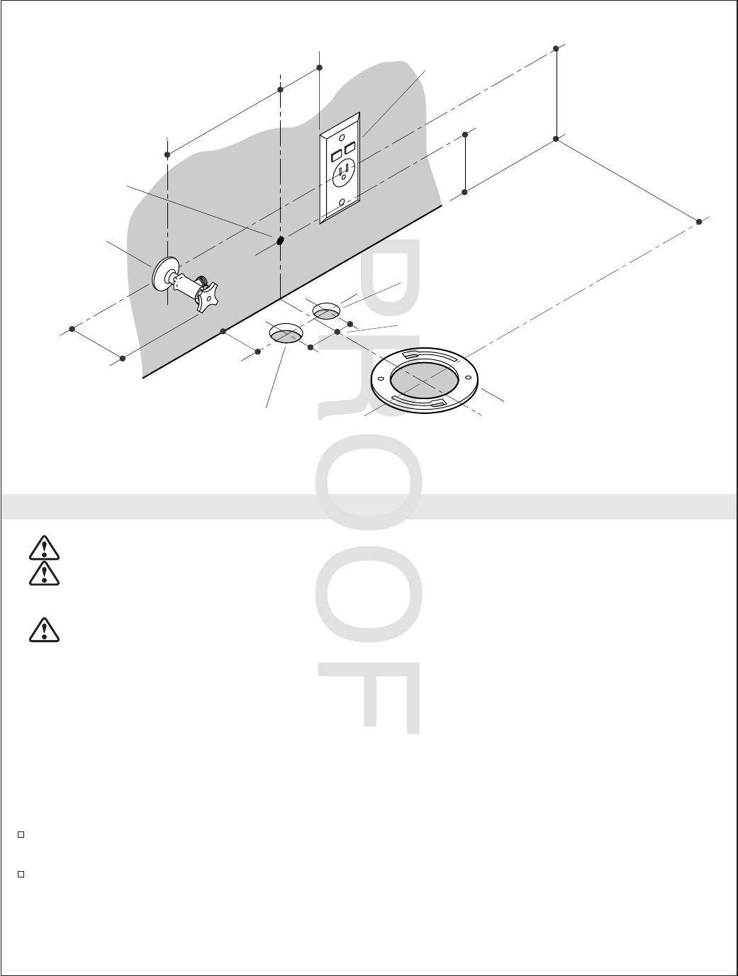
Prepare the Site
DANGER: Risk of electric shock. Disconnect power before installation or servicing.
DANGER: Risk of electric shock. Connect only to a properly-grounded, grounding-type receptacle
which is protected by a 120 V, 15 A, 60 Hz Ground-Fault Circuit-Interrupter (GFCI) or Residual
Current Device (RCD). Do not remove the grounding pin or use a grounding adapter.
DANGER: Risk of electrical shock. For hardwire installations/through-floor electrical supply:
Connect only to a properly-grounded, dedicated circuit protected by an Earth-Leakage
Circuit-Breaker (ELCB) or Residual Current Device (RCD).
NOTE: The electrical outlet and water supply may also be located behind the toilet. If it is located behind
the toilet, the water supply stop must extend no more than 3″(7.6 cm) beyond the finished wall. If located
behind the back wall, the supply stop must be a model that connects at a 90° angle. The handle should be
easily accessible.
NOTE: Locating the supply stop behind the toilet will make it difficult to remove the back panel. It may
be necessary to remove the toilet to service items behind the back panel.
Install the Dock Power Cord
If the finished wall has not been installed, route the docking station power cord. Drill a 3/8″(1 cm)
hole in the wall behind the toilet location for the dock cable.
If the finished wall is installed, drill a 3/8″(1 cm) hole in the wall behind the toilet location for the
docking station power cord. Route the cord to the docking station location.
Install the Water Supply
6" (15.2 cm)
12" (30.5 cm)
8" (20.3 cm)
Supply Stop
Floor Flange
GFCI-
Protected
Receptacle
3" (7.6 cm)
4" (10.2 cm)
Dock
Power
Cord
2" (5.1 cm)
1-1/2" (3.8 cm) D.
Water Supply Hole
1-1/4" (3.2 cm) D.
Power Supply Hole
2-5/8"
(6.7 cm)
1-1/4"
(3.2 cm)
1-5/8"
(4.1 cm)
1132336-2-A 6 Kohler Co.
Confirm wall mounted water supply and
electrical locations.
Adjust as needed for the Chinese
market.
Required for through the floor
installations only, remove these for
Chinese market.

JOBNAME: No Job Name PAGE: 7 SESS: 17 OUTPUT: Wed Jun 23 13:46:00 2010
Prepare the Site (cont.)
NOTE: The supplied water supply hose is 18″(45.7 cm) in length. The supplied hose must be used for this
installation.
Install the water supply and supply stop.
Install the Electrical Service
NOTE: The suppled power cord is 56″(142.2 cm) in length.
Locate a dedicated 120 V, 15 A, 60 Hz grounding-type receptacle, protected by a GFCI or RCD,
within 56″(142.2 cm) of the back of the toilet.
Kohler Co. 7 1132336-2-A
JOBNAME: No Job Name PAGE: 8 SESS: 17 OUTPUT: Wed Jun 23 13:46:00 2010
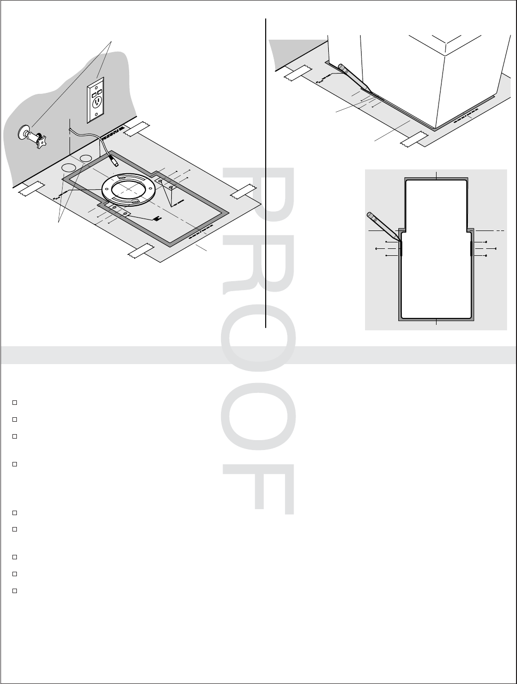
Prepare the Installation Location
IMPORTANT! Risk of product damage. If T-bolts are left in place, they will damage the toilet. Make sure
they are removed before moving the toilet into place.
If there are T-bolts in the flange, remove them. T-bolts are not required for this installation.
Cut out the inside of the flange area on the template.
Position the template with the hole positioned over the flange. It is critical that the centerlines
marked on the template are centered on the flange.
Secure the template to the floor with tape.
IMPORTANT! Because of the unique design of this toilet, the width of the bottom edges will vary. The
following steps are required because of this variation.
Confirm the template is correctly positioned and centered over the flange.
Position the toilet on the template. Make sure the front of the base of the toilet is aligned with the
markings on the template.
Position the toilet so an equal amount of shaded area is visible on each side of the template.
Confirm the toilet is centered by measuring the amount of space on each side of the template.
Directly under the screw holes on each side of the toilet, accurately mark the bottom edge of the
base. The mark should intersect the lines labeled ″C″and ″A″or ″B″on each side of the template.
Template
Screw Hole
Center the toilet
on the template.
Top View
For wall supply
installations only.
For through-
the-floor
supplies only.
1132336-2-A 8 Kohler Co.
Use template and line art for Chinese
market.
Template shown here has both
through-the-floor and out-the-back
installation information.
JOBNAME: No Job Name PAGE: 9 SESS: 17 OUTPUT: Wed Jun 23 13:46:00 2010
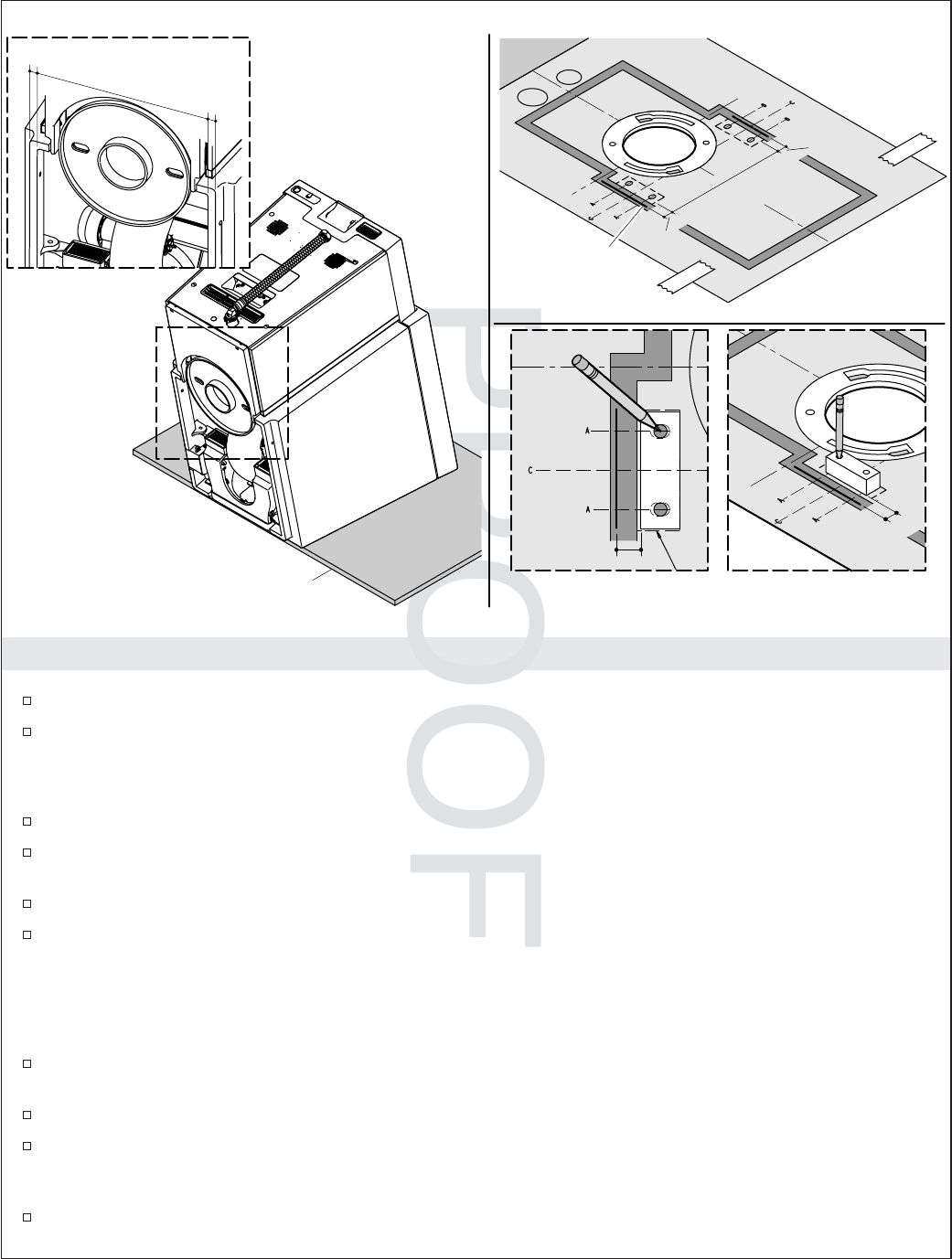
Determine Mounting Block Location
Position a rug or other protective material in front of the toilet.
Gently tilt the toilet forward until it rests on the front surface.
NOTE: The installation range of the mounting block is marked on the template. Due to variances in the
width of the base, the exact location must be determined by the installer.
Measure the width of the base, dimension ″A″, on the left side of the toilet.
From the mark indicating the outside edge of the base, measure inward and mark dimension ″A″on
the template line marked ″C″.
Measure the width of the base, dimension ″B″, on the right side of the toilet.
From the mark indicating the outside edge of the base, measure inward and mark dimension ″B″on
the template line marked ″C″.
IMPORTANT! The distance between the outside edges of the mounting block should be the same or
slightly less than dimension ″C″. The distance must not be more than 1/16″(2 mm) less than dimension
″C″, or the strength of the mounting block will be compromised.
On the template line marked ″C″, measure the distance between the marks that indicate the outside
edge of the mounting blocks. Compare this measurement to dimension ″C″.
Make sure the mounting blocks are correctly positioned.
Position the mounting blocks on the template with the outside edge aligned with the marks made
for dimensions ″A″or ″B″. With the side of the mounting blocks running parallel to the lines on the
template, mark the entire side of the mounting blocks.
With the side of the mounting blocks running parallel to the lines on the template, mark the entire
side of the mounting blocks.
A
B
C
Outside Edge
of Toilet
A
A
Top View
Protective Material
A
B
C
Kohler Co. 9 1132336-2-A
Use template and line art for Chinese
market.
Template shown here has both
through-the-floor and out-the-back
installation information.

JOBNAME: No Job Name PAGE: 10 SESS: 17 OUTPUT: Wed Jun 23 13:46:00 2010
Determine Mounting Block Location (cont.)
At the location of the screw holes in the side of the toilet, measure the width of the opening from
the inside edge of each side of the base, dimension ″C″. Use this dimension to confirm the correct
location of the blocks.
Insert a pencil into each of the four pre-drilled holes in the mounting blocks and mark the center of
the holes.
Remove the mounting blocks.
At the four locations where the centerline in the slots marked on the template and the pencil mark
indicating the hole locations meet, drill a 3/16″pilot hole.
Remove the template.
1132336-2-A 10 Kohler Co.
JOBNAME: No Job Name PAGE: 11 SESS: 17 OUTPUT: Wed Jun 23 13:46:00 2010
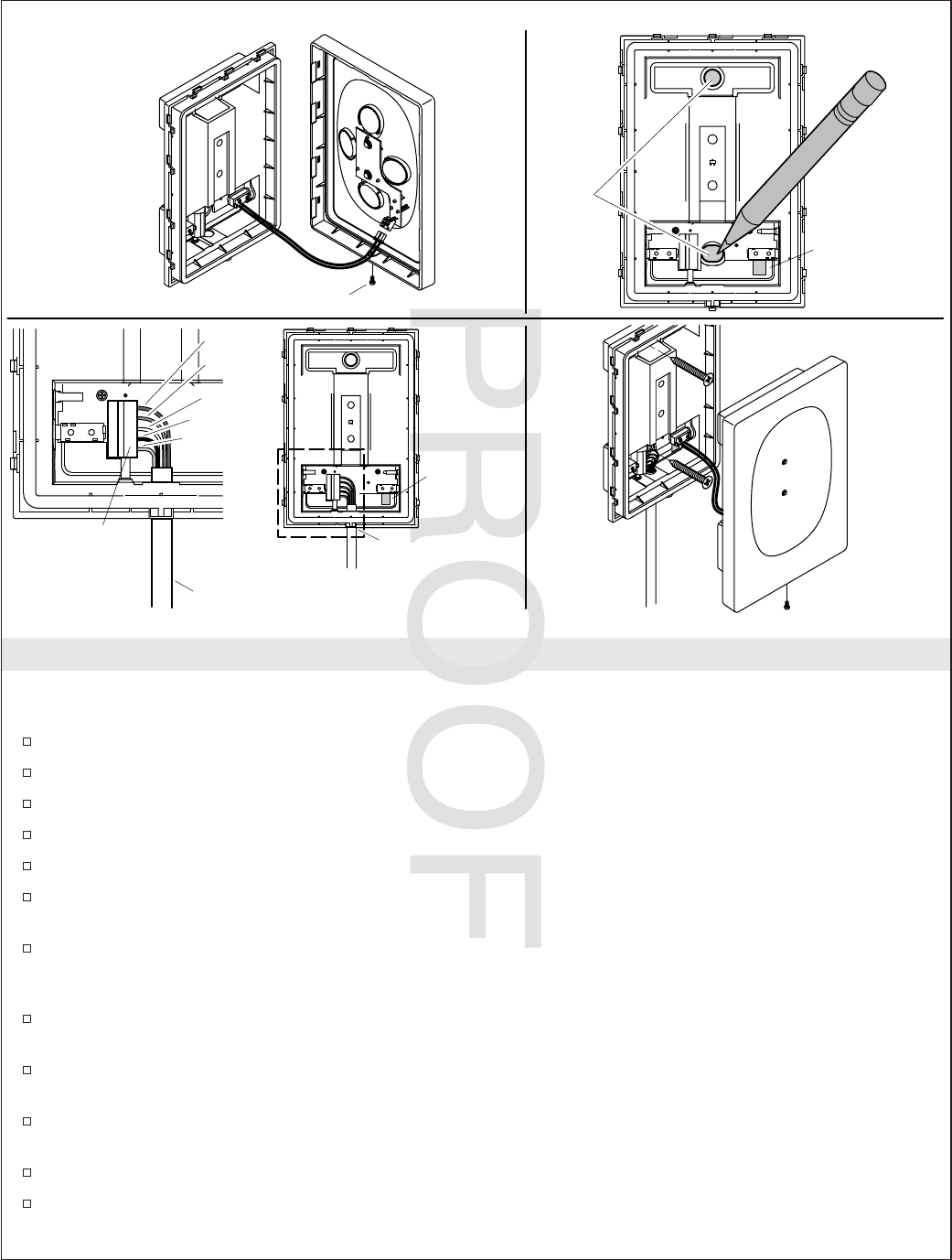
Install the Remote Dock
NOTE: The docking station comes with a 15’ (4.6 M) cord. Locate the docking station within 15’ (4.6 M) of
the toilet.
Remove the remote control from the dock and set aside.
Remove the small screw on the bottom of the docking station.
Carefully remove the cover plate.
Carefully disconnect the cover plate.
Tape the screw to the cover plate and set it aside.
For installation using the back cord opening, align the back power cord opening with the power
cord hole.
For installations using the bottom cord opening, align the docking station with the power cord
location, 1″(5.1 cm) below the center of the bottom screw hole, positioned so the cord is hidden
when the docking station is installed.
Position the docking station in the installation position and mark the screw locations using the dock
as a template.
Drill appropriate size mounting holes at the screw mounting locations. The size of the hole will
depend on need for wall anchors, wall material, and installation requirements.
If it has not already been done, run the docking station power cord from the toilet to the installation
location of the docking station.
Loosen each of the five small screws located where the wires will be connected.
Run the power cord into the docking station.
Holes
Red
Blue
White
Black
Orange
Screw
Connector
Harness
Docking Cord
Back Cord
Opening
Bottom Cord
Opening
Back Cord
Opening
Kohler Co. 11 1132336-2-A

JOBNAME: No Job Name PAGE: 12 SESS: 17 OUTPUT: Wed Jun 23 13:46:00 2010
Install the Remote Dock (cont.)
Slide the bare end of the wires into the correct port (as shown) and tighten each screw to secure the
wires in place.
Position the docking station over the wall anchors.
Connect the docking station to the wall using two screws.
Reconnect the cover plate.
Snap the cover plate back into place.
Secure the cover plate with the screw.
1132336-2-A 12 Kohler Co.
JOBNAME: No Job Name PAGE: 13 SESS: 17 OUTPUT: Wed Jun 23 13:46:00 2010
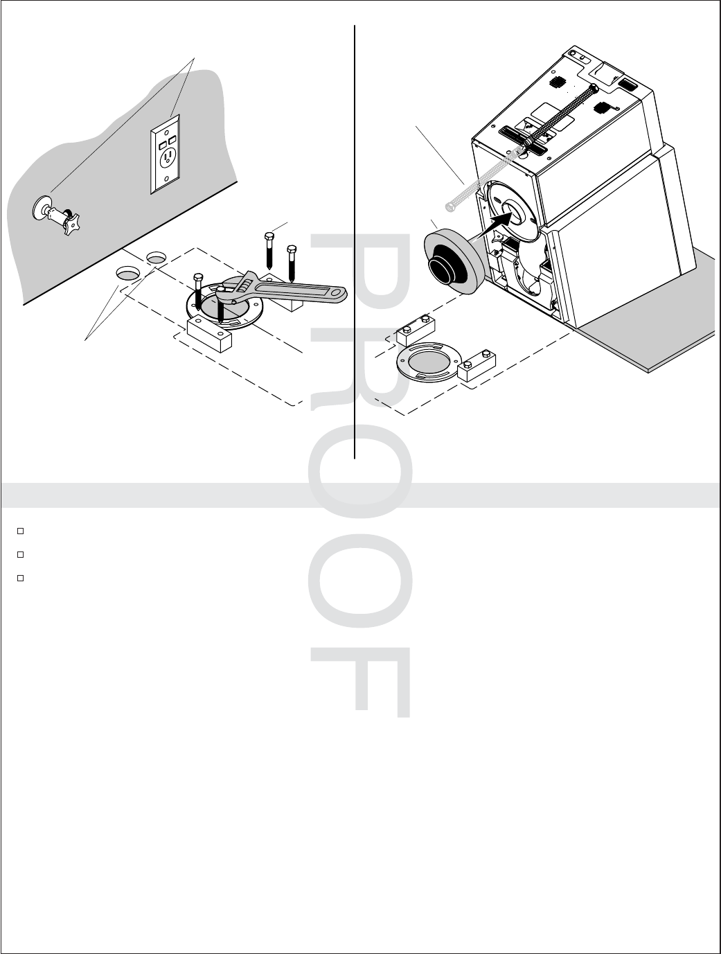
Install Mounting Blocks and Wax Ring
Position the mounting blocks over the mounting holes.
Secure each or the mounting blocks with two lag bolts.
Position a wax ring on the outlet.
Lag Bolt Wax Ring
For wall supply
installations only.
For through-
the-floor
supplies only.
Hose should face
down when through
floor.
Kohler Co. 13 1132336-2-A
Remove for Chinese market.
JOBNAME: No Job Name PAGE: 14 SESS: 17 OUTPUT: Wed Jun 23 13:46:00 2010
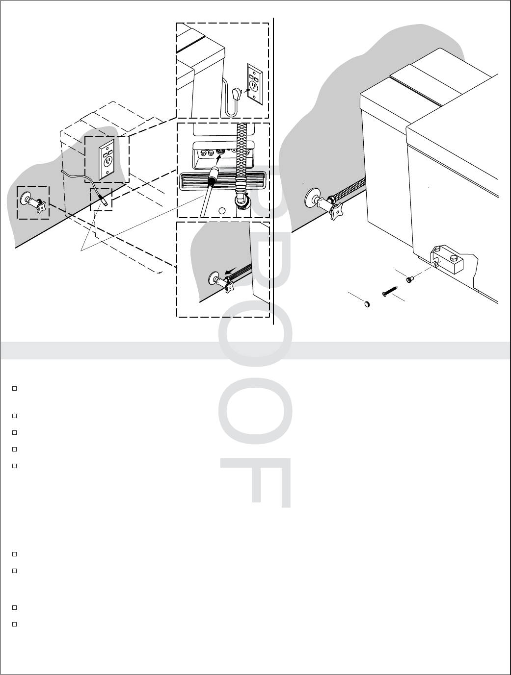
Install the Toilet
Position the Toilet
Carefully lower the toilet into place, making sure the water supply line and electrical cord avoid
interfering with the toilet when it is in place.
Connect the water supply to the supply stop.
Connect the docking station.
Connect the power.
Turn on the water supply.
Check for Leaks
NOTE: Once the power is connected, the toilet will automatically enter start-up mode. This process takes
several minutes.
NOTE: If there is a failure during start-up mode, follow the directions on the remote.
Once the start-up sequence has been completed flush the toilet.
Let the toilet fully refill and check for leaks.
Secure the Toilet
Secure the toilet to the mounting blocks using the supplied 6 mm x 30 mm screws.
Install the caps over the screw holes.
Cap
Screw
Bushing
Wall supply installation shown.
Docking
Station
Cord
1132336-2-A 14 Kohler Co.
JOBNAME: No Job Name PAGE: 15 SESS: 17 OUTPUT: Wed Jun 23 13:46:00 2010
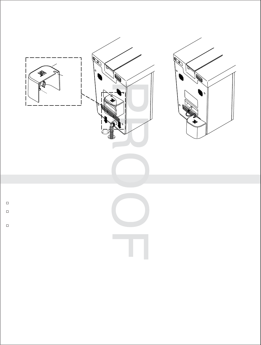
Installation the Back Cover
NOTE: Install the cover when the water and power supply are run through the floor. The cover is not
designed for use when the water or electrical are connected to wall supplies.
Position the cover over the water supply and electrical supply holes.
Align the spring clip on the cover with the supply hose inlet. The clip will snap into place on the
supply hose inlet to secure the cover.
Run the docking station cord through the slot in the cover and snap to cover into place on the
supply hose inlet.
Spring
Clip
Cover
Slot
Kohler Co. 15 1132336-2-A
JOBNAME: No Job Name PAGE: 16 SESS: 17 OUTPUT: Wed Jun 23 16:19:01 2010
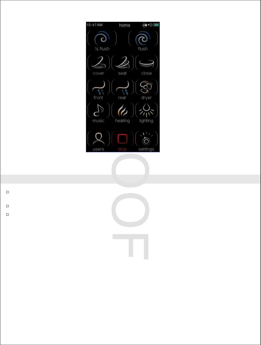
Check for Correct Operation
Make sure the remote is on the docking station. The remote should charge for 30 minutes before the
first use.
Press the power button located on the back of the toilet.
Press the flush button on the remote. Confirm the toilet flushes.
NOTE: After performing these steps, set the clock, date, and other remote functions following the
directions in the Homeowners Guide or on-line users guide in the ″Getting Started″section.
1132336-2-A 16 Kohler Co.

JOBNAME: No Job Name PAGE: 1 SESS: 1 OUTPUT: Wed Jun 23 13:46:00 2010
1132336-2-A

JOBNAME: No Job Name PAGE: 2 SESS: 1 OUTPUT: Wed Jun 23 13:46:00 2010
1132336-2-A

JOBNAME: No Job Name PAGE: 3 SESS: 1 OUTPUT: Wed Jun 23 13:46:00 2010
1132336-2-A

JOBNAME: No Job Name PAGE: 1 SESS: 1 OUTPUT: Wed Jun 23 13:46:00 2010
USA/Canada: 1-800-4KOHLER
México: 001-800-456-4537
kohler.com
©2010 Kohler Co.
1132336-2-A